LV 124 & LV 148 - Testforce | Test and Measurement ... Tolerances Standard tolerances LV 124 LV 148...
38
1 LV 124 & LV 148 Electrical normative basics and practical challenges for vehicle components and systems CONDUCTED RF EQUIPMENT POWER AMPLIFIERS Markus Fuhrer 05.04.2016
Transcript of LV 124 & LV 148 - Testforce | Test and Measurement ... Tolerances Standard tolerances LV 124 LV 148...

1
LV 124 & LV 148 Electrical normative basics and practical
challenges for vehicle components and systems
CONDUCTED RF EQUIPMENT POWER AMPLIFIERS
Markus Fuhrer 05.04.2016

Content
1. Electrical requirements and tests of LV 124 and LV 148
- LV 124: Electrical and electronic components in motor vehicles up to 3,5t
- LV 148: Electrical and electronic components in motor vehicles 48V electrical system
1.1 Terms and Definitions
1.2 Electrical requirements and tests
- LV 124: E-01 to E-22
- LV 148: E48-01 to E48-21
2

Standard overview of the LV standards
LV124 LV 148 Electric and Electronic Components Electric and Electronic Components
in Motor Vehicles up to 3.5t - for Vehicles with a
General Requirements 48V Electrical System
Test Conditions and Tests Test Conditions and Tests
Verband der VDA 320 Version August 2014
Automobilindustrie
BMW GS 95024--2--1 Ausgabe: 2010-01 GS 95026 (2013-05)
Mercedes MBN LV 124-1 Ausgabe: 2013-03 MBN LV 148 2013-11
Volkswagen VW 80000 Ausgabe 2013-06
3
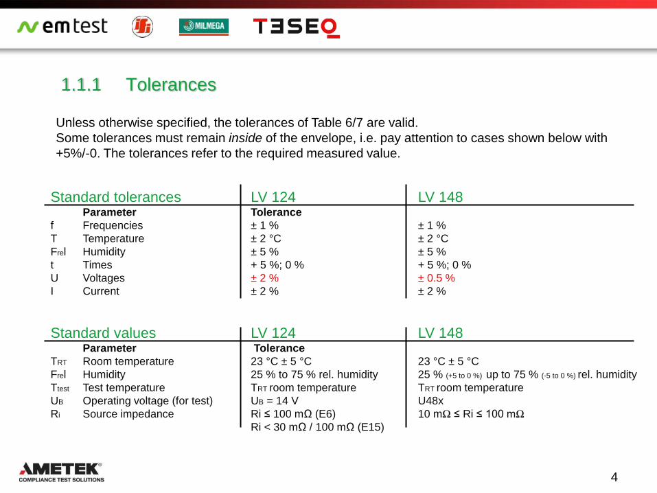
1.1.1 Tolerances
Standard tolerances LV 124 LV 148 Parameter Tolerance
f Frequencies ± 1 % ± 1 %
T Temperature ± 2 °C ± 2 °C
Frel Humidity ± 5 % ± 5 %
t Times + 5 %; 0 % + 5 %; 0 %
U Voltages ± 2 % ± 0.5 %
I Current ± 2 % ± 2 %
Standard values LV 124 LV 148 Parameter Tolerance
TRT Room temperature 23 °C ± 5 °C 23 °C ± 5 °C
Frel Humidity 25 % to 75 % rel. humidity 25 % (+5 to 0 %) up to 75 % (-5 to 0 %) rel. humidity
Ttest Test temperature TRT room temperature TRT room temperature
UB Operating voltage (for test) UB = 14 V U48x
Ri Source impedance Ri ≤ 100 mΩ (E6) 10 mΩ ≤ Ri ≤ 100 mΩ
Ri < 30 mΩ / 100 mΩ (E15)
4
Unless otherwise specified, the tolerances of Table 6/7 are valid.
Some tolerances must remain inside of the envelope, i.e. pay attention to cases shown below with
+5%/-0. The tolerances refer to the required measured value.
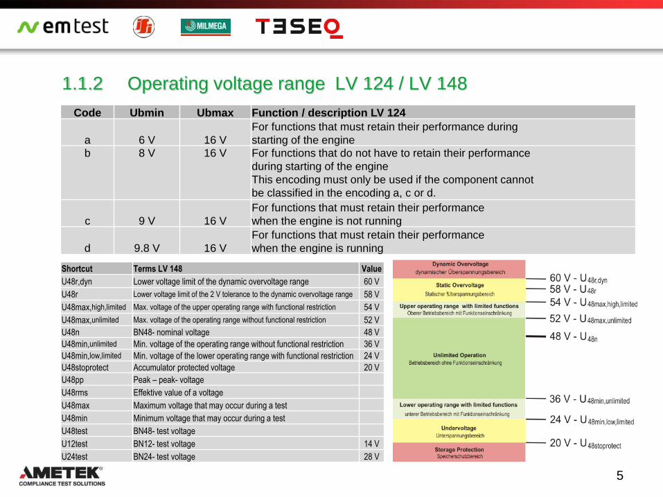
1.1.2 Operating voltage range LV 124 / LV 148
5
Code Ubmin Ubmax Function / description LV 124
a 6 V 16 V
For functions that must retain their performance during
starting of the engine
b 8 V 16 V For functions that do not have to retain their performance
during starting of the engine
This encoding must only be used if the component cannot
be classified in the encoding a, c or d.
c 9 V 16 V
For functions that must retain their performance
when the engine is not running
d 9.8 V 16 V
For functions that must retain their performance
when the engine is running
Shortcut Terms LV 148 Value
U48r,dyn Lower voltage limit of the dynamic overvoltage range 60 V
U48r Lower voltage limit of the 2 V tolerance to the dynamic overvoltage range 58 V
U48max,high,limited Max. voltage of the upper operating range with functional restriction 54 V
U48max,unlimited Max. voltage of the operating range without functional restriction 52 V
U48n BN48- nominal voltage 48 V
U48min,unlimited Min. voltage of the operating range without functional restriction 36 V
U48min,low,limited Min. voltage of the lower operating range with functional restriction 24 V
U48stoprotect Accumulator protected voltage 20 V
U48pp Peak – peak- voltage
U48rms Effektive value of a voltage
U48max Maximum voltage that may occur during a test
U48min Minimum voltage that may occur during a test
U48test BN48- test voltage
U12test BN12- test voltage 14 V
U24test BN24- test voltage 28 V
6
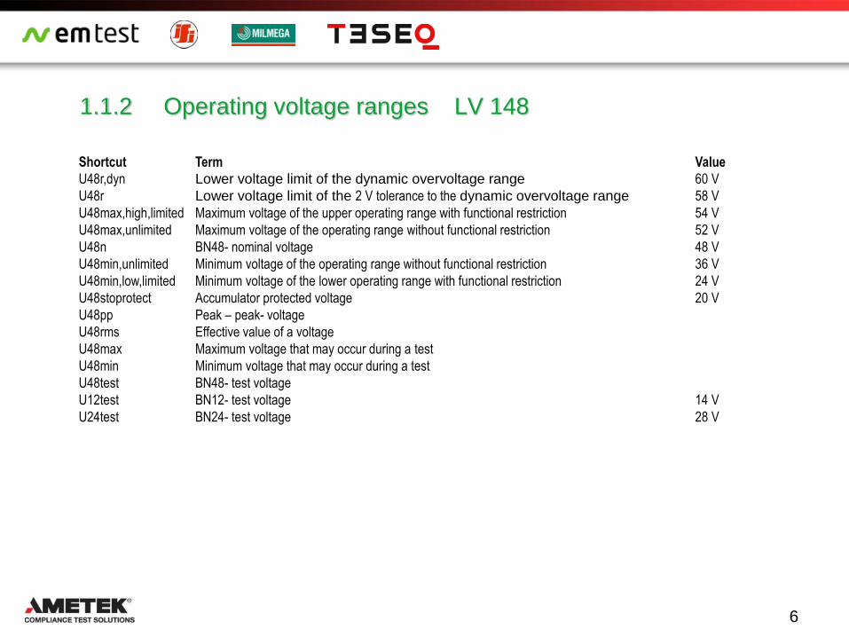
1.1.2 Operating voltage ranges LV 148
Shortcut Term Value
U48r,dyn Lower voltage limit of the dynamic overvoltage range 60 V
U48r Lower voltage limit of the 2 V tolerance to the dynamic overvoltage range 58 V
U48max,high,limited Maximum voltage of the upper operating range with functional restriction 54 V
U48max,unlimited Maximum voltage of the operating range without functional restriction 52 V
U48n BN48- nominal voltage 48 V
U48min,unlimited Minimum voltage of the operating range without functional restriction 36 V
U48min,low,limited Minimum voltage of the lower operating range with functional restriction 24 V
U48stoprotect Accumulator protected voltage 20 V
U48pp Peak – peak- voltage
U48rms Effective value of a voltage
U48max Maximum voltage that may occur during a test
U48min Minimum voltage that may occur during a test
U48test BN48- test voltage
U12test BN12- test voltage 14 V
U24test BN24- test voltage 28 V

Content
Chapter LV 124 LV 148 Title
1.2.1 Test Setup for electrical tests
1.2.2 E-01, E48-01a,b Long-term overvoltage
1.2.2 E-02, E48-02 Transient overvoltage
1.2.3 E-03, E48-03 Transient undervoltage
1.2.4 E-04, E48-04 Jumpstart, (Recuperation)
1.2.5 E-05 Load Dump
1.2.6 E-06, E48-05 Superimposed AC voltage
1.2.7 E-07, E48-06a,b,c Slow decrease and increase of the supply voltage
1.2.8 E-08, E48-07 Slow decrease, fast increase of the supply voltage
1.2.9 E-09, E48-08 Reset behavior
1.2.10 E-10, E48-09 Short interruptions
1.2.11 E-11, E48-10 Start impulse
1.2.12 E-12, Voltage characteristic in vehicle power supply control
1.2.13 E-13 Interruption Pin
1.2.14 E-14 Interruption Plug
1.3 Other tests of LV 124 and LV 148
1.2. Electrical requirements and tests
7

1.2.1 Test setup for electrical tests
Test setup for voltage simulation:
- DC source
- Signal generator
- Auxiliary equipment
- Measuring devices
Test setup for voltage dropouts
- DC source
- Electronic switch
- Signal generator
- Auxiliary equipment
- Measuring devices
8

1.2.2 E-01, E48-01a Long-term over voltages
Purpose: The component's resistance to long-term overvoltage is tested. A generator control fault
during driving operation is simulated.
Parameter LV 124 LV 148
Operating mode DUT Operating mode II.c Operating mode II.a, II.b and II.c
Umax 17 V (+4 %, 0 %) 60,0 V ,U48r,dyn
Umin 13,5 V 48.0 V, U48n
tr < 10 ms 0.1s
tf < 10 ms
t1 60 min 60 min
Ttest Tmax – 20K Tmax - 20 °C
Number of cycles 1 1
Number of test samples at least 6 6
Requirements Function status
a) Components which convert el. Energy B
b) Required function while driving B
c) All other components C
9

1.2.2 E48-01b Overvoltages on recuperating components
Purpose: Testing for recuperation components in the electrical system where the energy can not
be removed and therefore it results in a over voltage.
Part 1
Test with a source which does not act as
a sink. Regenerative current < 10 mA
Part 2
Test with 4-Quadrant – amplifier
- The regenerative current must be measured ≤ 10 mA
is accepted
- The time t1 must not exceede
Test Part 1 Part 2
Operating mode DUT Operating modeII.c
Test temperature Ttest Tmin, TRT und Tmax
U1 52 V, U48max,unlimited
U2 58 V, U48r
U3 54 V, U48max,high,limited
t0 start of recuperation ≥ 1 s ≥ 1 s
t1 ≤ 300 ms ≤ 300 ms
toff - ≤ 10 μs
Number of cycles each 3 Zyklen at all 3 temperatures
Number of test samples 6
10
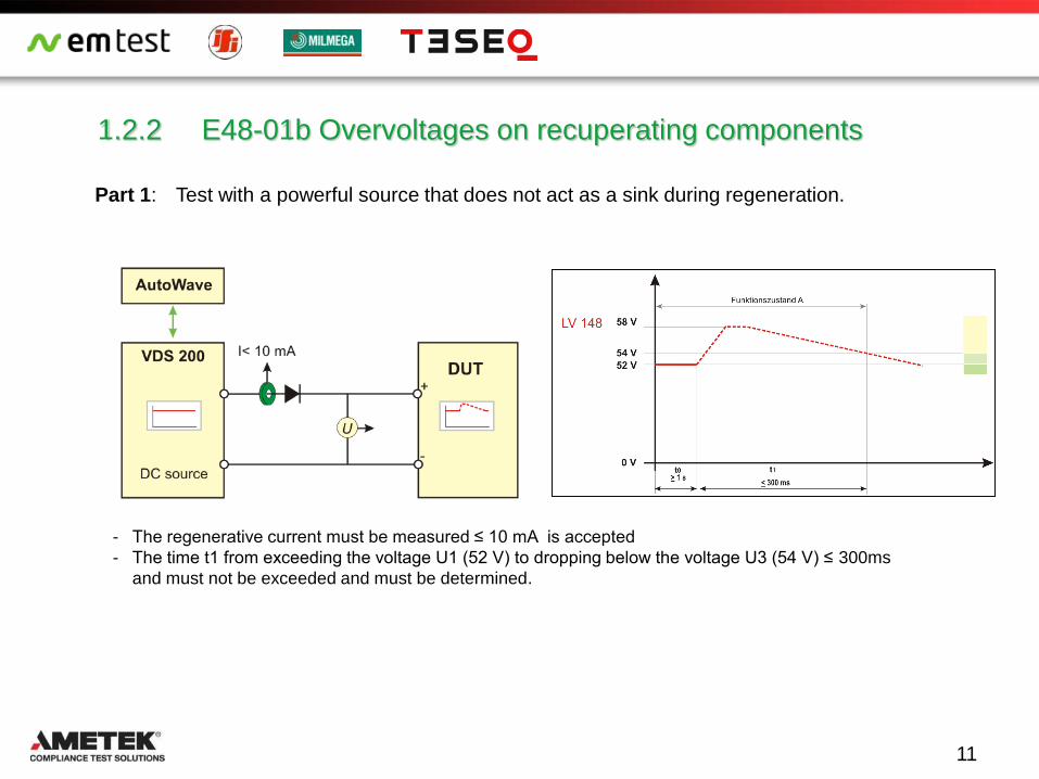
1.2.2 E48-01b Overvoltages on recuperating components
Part 1: Test with a powerful source that does not act as a sink during regeneration.
- The regenerative current must be measured ≤ 10 mA is accepted
- The time t1 from exceeding the voltage U1 (52 V) to dropping below the voltage U3 (54 V) ≤ 300ms
and must not be exceeded and must be determined.
11

1.2.2 E48-01b Overvoltages on recuperating components
Part 2: The DUT is connected to a powerful 4 quadrant amplifier and must be operated for at least
t0 at U1. Thereafter, the activation of the feedback begins and at maximum regenerative
current of the DUT, the decrease in the regenerative power abruptly (toff) must be terminated.
Test with 4-Quadrant – amplifier - Operate the DUT at least during >1s (t0) at U1.
- Then activate the recuperation
- At max. recuperation current stop the recuperation to the source
at toff within 10us.
- Measure the recuperation current ≤ 10 mA is accepted
- The time t1 from the voltage exceeding U1 (300ms) must not be
exceeded and must be determined.
12
toff

1.2.2 E-02, E48-02 Transiente overvoltages
LV 124 : 3 Test cases on different temperatures;
Functional status: A
LV 148: 2 tests, short test 3x, long duration test 1000x, Ri: 10 mΩ ≤ Ri ≤ 100 mΩ
Functional status: A
6 test samples
13
Purpose: Transient overvoltages may occur in the electric system due to the switching off of loads
and due to short accelerator tip-ins. These overvoltages are simulated by means of this
test.

1.2.3 E-03, E48-03 Transiente Undervoltages
Purpose: Transient undervoltages in the electric system may occur due to switching on of loads.
These undervoltages are simulated by means of this test.
Requirements LV 124 LV 148
Number of cycles: ever 3 at Tmax and Tmin 1
Number of samples: at least 6 6
Functional status: A B
14
10.8 V (+4 %, 0 %)
9.0 V (0 %, -4 %)

1.2.4 E-04, E48-04 Jumpstart, resp. Recuperation
Purpose: Jump starting of the vehicle is simulated. The maximum test voltage results from
commercial vehicle systems and their elevated electric system voltages.
LV 148: Longer recuperation is simulated.
Requirements LV 124 LV 148
Number of cycles: 1 1
Number of samples: mind. 6 6
Functional status: C A (driving mode relevant) B all others
15
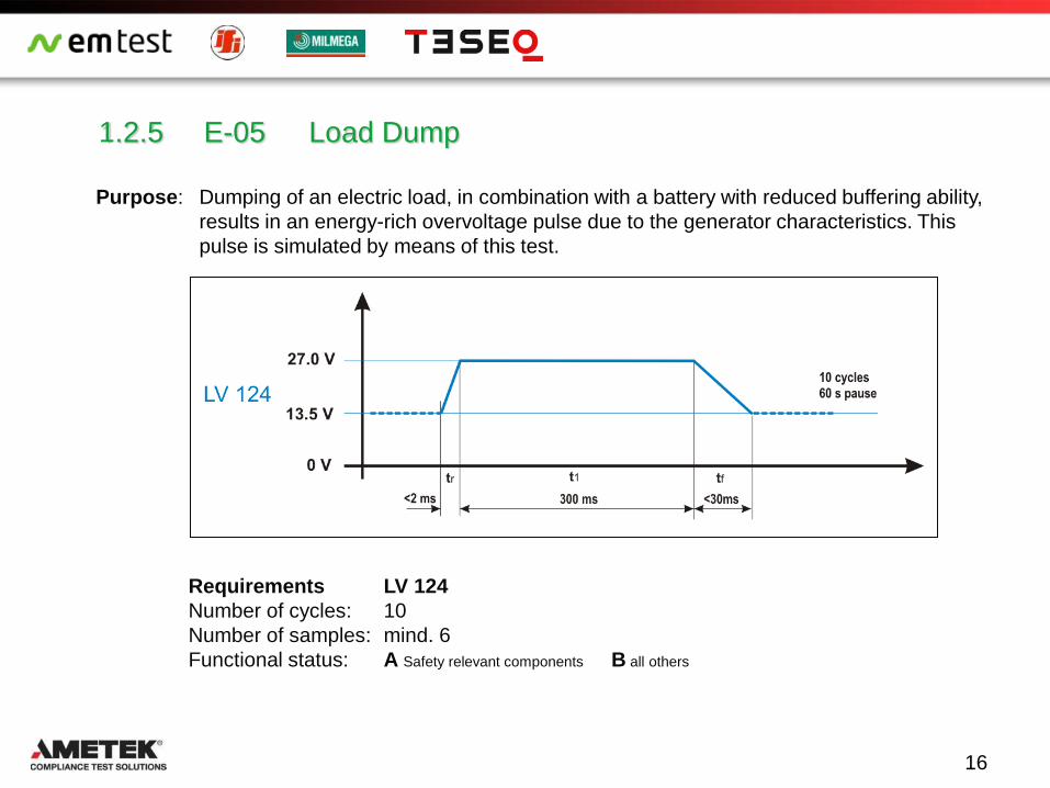
1.2.5 E-05 Load Dump
Requirements LV 124
Number of cycles: 10
Number of samples: mind. 6
Functional status: A Safety relevant components B all others
16
Purpose: Dumping of an electric load, in combination with a battery with reduced buffering ability,
results in an energy-rich overvoltage pulse due to the generator characteristics. This
pulse is simulated by means of this test.
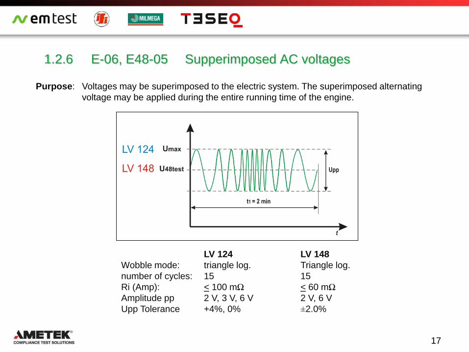
1.2.6 E-06, E48-05 Supperimposed AC voltages
Purpose: Voltages may be superimposed to the electric system. The superimposed alternating
voltage may be applied during the entire running time of the engine.
LV 124 LV 148
Wobble mode: triangle log. Triangle log.
number of cycles: 15 15
Ri (Amp): < 100 mΩ < 60 mΩ
Amplitude pp 2 V, 3 V, 6 V 2 V, 6 V
Upp Tolerance +4%, 0% ±2.0%
17

1.2.6 E-06, E48-05 Superimposed AC voltages
U48max,unlimited
U48min,unlimited
UBmax
Requirements LV 124 LV 148
Number of cycles: 15 1
Number of samples: minimum 6 6
Functional status: Test case 1 (2 Vpp) and 2 (3 Vpp): A A
Test case 3: (6 Vpp) A (driving mode relevant), Rest B B all others
18
Purpose: Voltages may be superimposed to the electric system. The superimposed alternating
voltage may be applied during the entire running time of the engine.

1.2.7 E-07, E48-06a Slow decrease and increase of the supply voltage
Purpose: The slow decrease and increase of the supply voltage is simulated as it occurs during
the slow discharging and charging procedure of the vehicle battery.
Requirements LV 124 LV 148
Number of cycles: 1 1
Number of samples: min. 6 6
Functional status: A Inside the defined operating voltage depends on voltage range
C Outside the defined operating voltage
19
t1: Read error memory

1.2.7 E48-06b Slow decrease of the supply voltage, Operating with energy storage Part 1
1. 2 Elektrische Requirements und Prüfungen
Requirements LV 148
Number of cycles: 1
Number of samples: 6
Functional status: Depends on voltage range
20
Purpose: Checks will slow the supply voltage decrease to the energy storage protection voltage,
followed by energy storage disconnection.
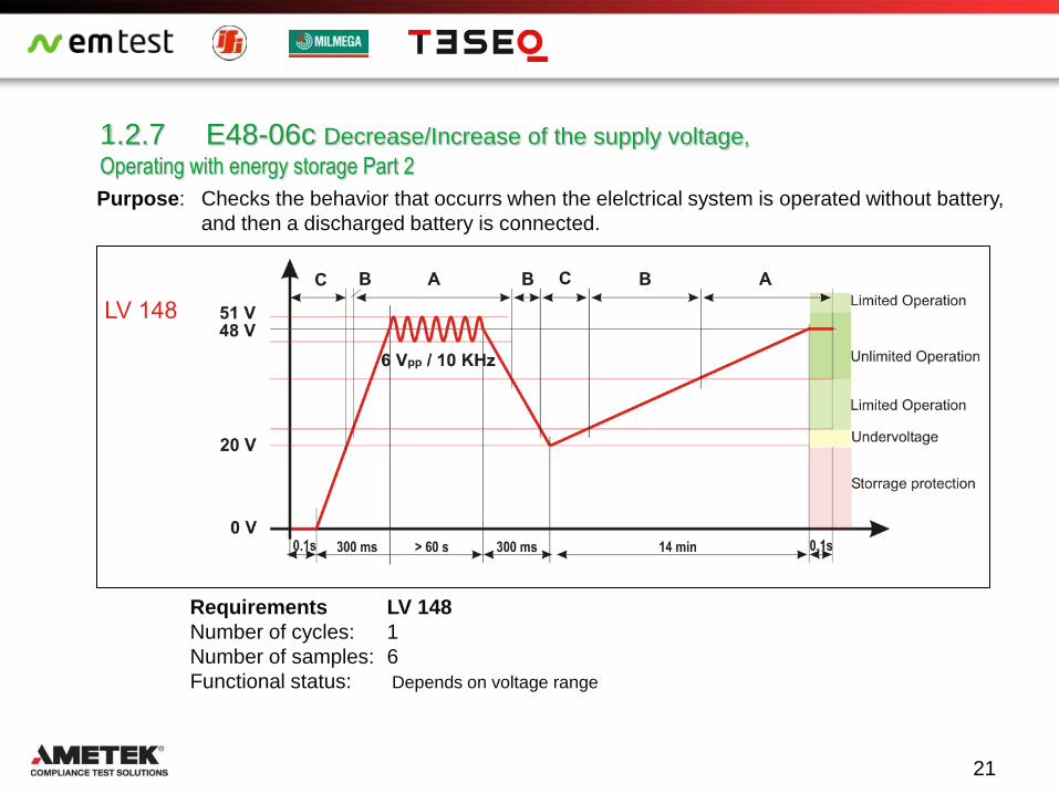
1.2.7 E48-06c Decrease/Increase of the supply voltage,
Operating with energy storage Part 2
Purpose: Checks the behavior that occurrs when the elelctrical system is operated without battery,
and then a discharged battery is connected.
Requirements LV 148
Number of cycles: 1
Number of samples: 6
Functional status: Depends on voltage range
21

1.2.8 E-08, E48-07 Slow decrease, fast increase in the supply voltage
Requirements LV 124 LV 148
Number of cycles: 1 per operating mode II.a / II.c 1 operating mode II a
Number of samples: minimum 6 6
Functional status: A Inside the defined operating voltage A at test end
C Outside the defined operating voltage
22
Purpose:
LV 124 This test simulates the slow decrease of the
battery voltage to 0 V and the sudden
reapplication of the battery voltage, e.g., by
applying a jump start source.
LV 148 This test simulates the slow decrease of the
vehicle system voltage to the energy storage
protection voltage followed by shutdown to 0V
and the sudden reconnect the system voltage by
a charged or new energy storage battery.
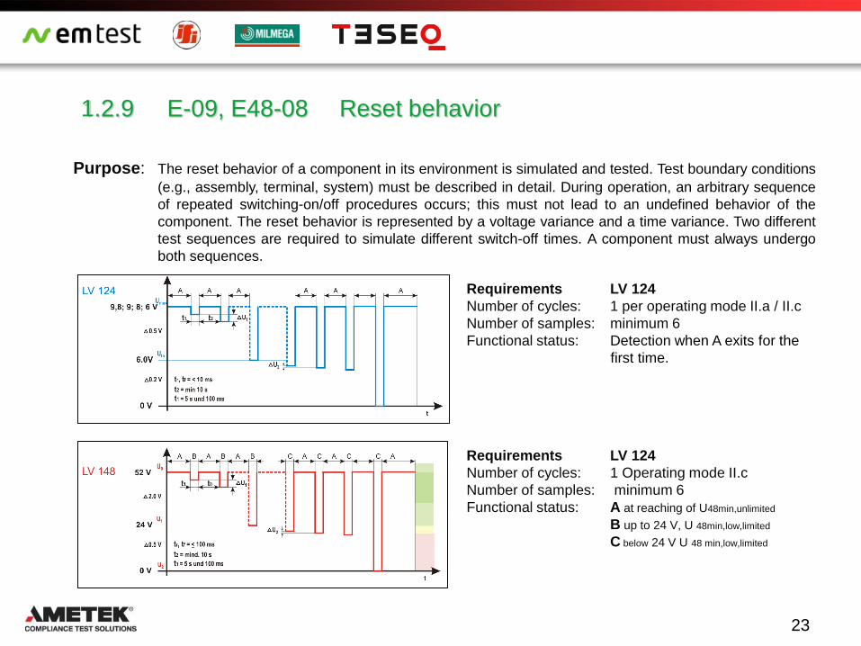
1.2.9 E-09, E48-08 Reset behavior
Requirements LV 124
Number of cycles: 1 per operating mode II.a / II.c
Number of samples: minimum 6
Functional status: Detection when A exits for the
first time.
Requirements LV 124
Number of cycles: 1 Operating mode II.c
Number of samples: minimum 6
Functional status: A at reaching of U48min,unlimited
B up to 24 V, U 48min,low,limited
C below 24 V U 48 min,low,limited
23
Purpose: The reset behavior of a component in its environment is simulated and tested. Test boundary conditions
(e.g., assembly, terminal, system) must be described in detail. During operation, an arbitrary sequence
of repeated switching-on/off procedures occurs; this must not lead to an undefined behavior of the
component. The reset behavior is represented by a voltage variance and a time variance. Two different
test sequences are required to simulate different switch-off times. A component must always undergo
both sequences.
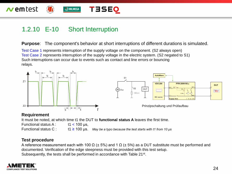
1.2.10 E-10 Short Interruption
Purpose: The component's behavior at short interruptions of different durations is simulated.
Test Case 1 represents interruption of the supply voltage on the component. (S2 always open)
Test Case 2 represents interruption of the supply voltage in the electric system. (S2 negated to S1)
Such interruptions can occur due to events such as contact and line errors or bouncing
relays.
Requirement It must be noted, at which time t1 the DUT to functional status A leaves the first time.
Functional status A : t1 < 100 μs,
Functional status C : t1 ≥ 100 μs. May be a typo because the test starts with t1 from 10 μs
Test procedure A reference measurement each with 100 Ω (± 5%) and 1 Ω (± 5%) as a DUT substitute must be performed and
documented. Verification of the edge steepness must be provided with this test setup.
Subsequently, the tests shall be performed in accordance with Table 21st.
Prinzipschaltung und Prüfaufbau
24
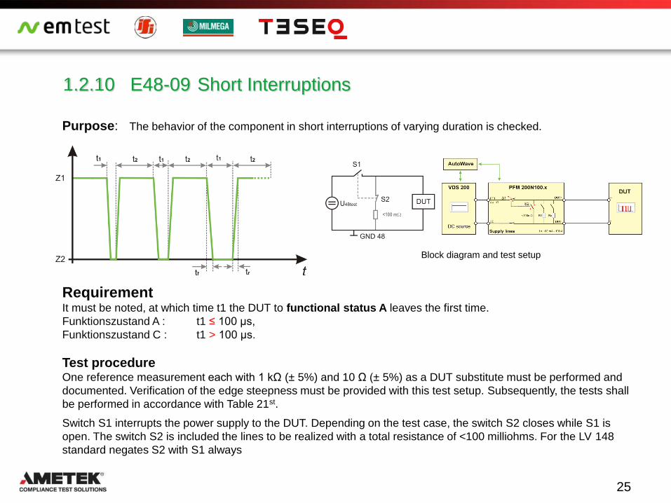
1.2.10 E48-09 Short Interruptions
Purpose: The behavior of the component in short interruptions of varying duration is checked.
Requirement It must be noted, at which time t1 the DUT to functional status A leaves the first time.
Funktionszustand A : t1 ≤ 100 μs,
Funktionszustand C : t1 > 100 μs.
Test procedure One reference measurement each with 1 kΩ (± 5%) and 10 Ω (± 5%) as a DUT substitute must be performed and
documented. Verification of the edge steepness must be provided with this test setup. Subsequently, the tests shall
be performed in accordance with Table 21st.
Switch S1 interrupts the power supply to the DUT. Depending on the test case, the switch S2 closes while S1 is
open. The switch S2 is included the lines to be realized with a total resistance of <100 milliohms. For the LV 148
standard negates S2 with S1 always
Block diagram and test setup
25
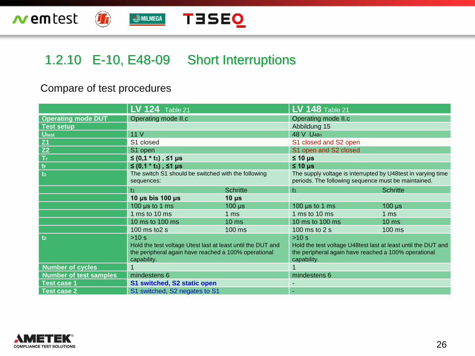
1.2.10 E-10, E48-09 Short Interruptions
Compare of test procedures
LV 124 Table 21 LV 148 Table 21
Operating mode DUT Operating mode II.c Operating mode II.c
Test setup Abbildung 15
Utest 11 V 48 V U48n
Z1 S1 closed S1 closed and S2 open
Z2 S1 open S1 open and S2 closed
Tr ≤ (0,1 * t1) , ≤1 μs ≤ 10 μs
tf ≤ (0,1 * t1) , ≤1 μs ≤ 10 μs
t1 The switch S1 should be switched with the following
sequences:
The supply voltage is interrupted by U48test in varying time
periods. The following sequence must be maintained.
t1 Schritte t1 Schritte
10 μs bis 100 μs 10 μs
100 μs to 1 ms 100 μs 100 μs to 1 ms 100 μs
1 ms to 10 ms 1 ms 1 ms to 10 ms 1 ms
10 ms to 100 ms 10 ms 10 ms to 100 ms 10 ms
100 ms to2 s 100 ms 100 ms to 2 s 100 ms
t2 >10 s Hold the test voltage Utest last at least until the DUT and
the peripheral again have reached a 100% operational
capability.
>10 s Hold the test voltage U48test last at least until the DUT and
the peripheral again have reached a 100% operational
capability.
Number of cycles 1 1
Number of test samples mindestens 6 mindestens 6
Test case 1 S1 switched, S2 static open -
Test case 2 S1 switched, S2 negates to S1 -
26

1.2.10 E-10, E48-09 Short Interruptions
Reference measurement LV 124: 11 V with 100 Ω (1.2 W) and 1 Ω (121 W)
LV 148: 48 V with 1000 Ω (2.3 W) and 10 Ω (230 W)
When measuring, please note that the low-power resistors become
quite warm. Therefore, the load resistors are used only during the
reference measurement.
A switching time ≤1 microseconds requires low-inductance resistors
with short leads. A load of 1000 Ω and 200 pF adopted stray
capacitance already results in a RC time constant of 200 ns.
Example reference measurement for LV 124
Load resistor 1 Ω 100 Ω
Rise Time tr: 336 ns 281 ns
Fall Time tf 573 ns 235 ns
27

1.2.10 E-10, E48-09 Short Interruptions
Test setup
The DC power supply is a source, which must be able to provide the required inrush currents when closing the
switch. The standard requires a high-ohmic resistance for disconnect the source and a direct short circuit of the
DUT with max. 100m Ω. This requires a fast switch with internally switchable discharge resistor.
The discharge time is mainly determined by the impedance of the DUT. A drop in the voltage at the DUT to 0 volts
within 1us is achieved in this application only in DUTs with low impedance with fast self-discharge and a small DUT
capacitance.
If the DUT has a high impedance and has a high input capacitance of several tens of microfarads to mF (which is
common for buffer capacitors) the interruption duration only allows a reduced voltage drop. It is quite possible that
the voltage during the interruption does not drop to zero.
Test case 1 S1 switched, S2 static open Testcase 2 S1 switched, S2 S2 negate to S1
28
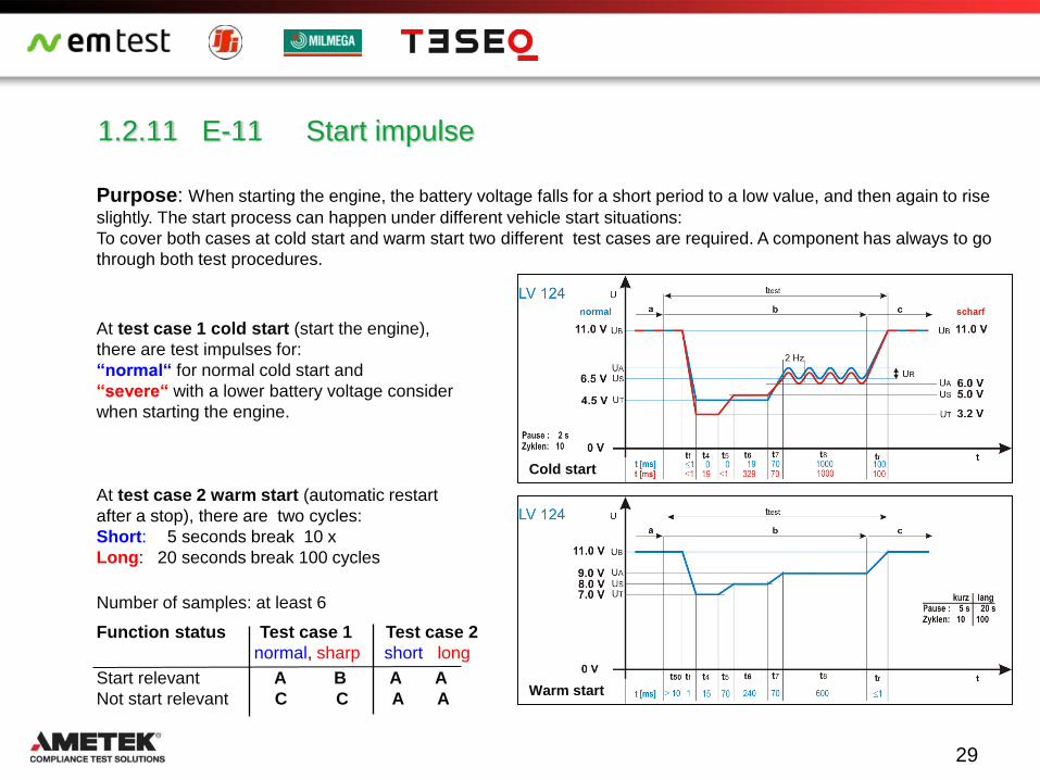
Purpose: When starting the engine, the battery voltage falls for a short period to a low value, and then again to rise
slightly. The start process can happen under different vehicle start situations:
To cover both cases at cold start and warm start two different test cases are required. A component has always to go
through both test procedures.
At test case 1 cold start (start the engine),
there are test impulses for:
“normal“ for normal cold start and
“severe“ with a lower battery voltage consider
when starting the engine.
At test case 2 warm start (automatic restart
after a stop), there are two cycles:
Short: 5 seconds break 10 x
Long: 20 seconds break 100 cycles
Number of samples: at least 6
Function status Test case 1 Test case 2
normal, sharp short long
Start relevant A B A A
Not start relevant C C A A
1.2.11 E-11 Start impulse
Cold start
Warm start
29

1.2.11 E48-10 Start impulse
Purpose: During a cold start (motor start), the energy storage battery voltage decreases for a
short, then increases again. The warm start is not considered, because the operating
range is maintained.
Requirements
Number of cycles: 10
Number of samples: 6
It is not allowed to have an input to the error memory. The vehicle must be able to be started in any case.
Functional status: A for start relevant components
Functional status: B for not start relevant components
Test impulse: E48-10 Start impulse
30

1.2.12 E-12 Voltage curve with electric system control
Purpose: The behavior of the electric system with voltage controls, e.g., with the use of intelligent
generator controls or DC-DC converter controls, is simulated.
Functional status A
Operating mode of DUT Operating mode II.c
Umin (11,8 V - dU) (0 %, -4 %)
Umax (15 V - dU) (+4 %, 0 %)
t1 2 s
tr ≥300 ms
tf ≥300 ms
Number of cycles 10
Number of samples at least 6
31

1.2.13 E-13 Interruption Pin
Z1 Status 1: Pin connected
Z2 Status 2: Pin interrupted
tr, tf ≤ (0,1 * t1) = 10us
Anzahl der Zyklen each 3 cyclles Operating mode
II.a / Iic
Anzahl Prüflinge minimum 6
Testfall 2 4 000 Impulses t2 in pulse packet
t1 0,1 ms
t2 1 ms
t3 10 s
Functional status C for all test cases
32
Purpose: The supply line interruption of individual pins is simulated. The test must be performed in
two different operating states. Different pulse forms must be used, because the possible
interruptions may differ greatly regarding their duration (from loose contacts to
permanent interruption).
Test Case 1: Each pin must disconnected for = 10s
and reconnected (slow interval)
Test Case 1
Test Case 2: Pulse packet on each pin to simulate a "loose contact" see picture
Test Case 2

1.2.13 E-13 Interruption Pin
Switch for current range 100 mA to 100 A Switch for current range 100 µA to2 A (16 channels)
33
Test procedure: The DUT is connected to a battery source.
The test is not for power lines (e.g. T.15, T.30, T.87, …) instead on signal or data lines
as well as T.31 return lines.
The voltage at pin can be limited to the maximum voltage of the test E-05 Load Dump (Umax 27 V).
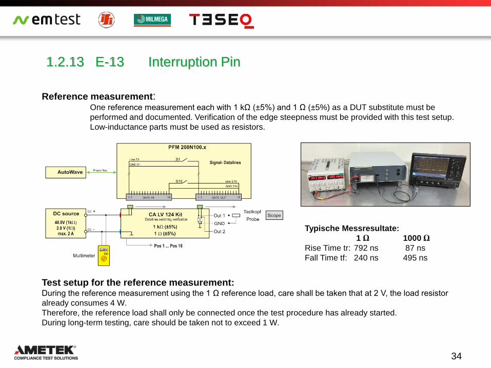
1.2.13 E-13 Interruption Pin
Reference measurement: One reference measurement each with 1 kΩ (±5%) and 1 Ω (±5%) as a DUT substitute must be
performed and documented. Verification of the edge steepness must be provided with this test setup.
Low-inductance parts must be used as resistors.
Test setup for the reference measurement: During the reference measurement using the 1 Ω reference load, care shall be taken that at 2 V, the load resistor
already consumes 4 W.
Therefore, the reference load shall only be connected once the test procedure has already started.
During long-term testing, care should be taken not to exceed 1 W.
Typische Messresultate:
1 Ω 1000 Ω
Rise Time tr: 792 ns 87 ns
Fall Time tf: 240 ns 495 ns
34

1.2.14 E-14 Interruption Connector
Purpose: The line interruption of connectors is simulated.
Test procedure Each connector must be removed from the DUT for 10 s and then replaced. If the DUT has several connectors, each
connector must be tested individually. The test sequence must be variable. In case that there are multiple connectors,
every connector must be tested.
Execution of test
Theoretically, you can disconnect the plug by hand for 10 s. When interrupting high DC currents resulting sparking and
burn-out when open the circuit. Far less dangerous is the high-impedance isolation with an electronic switch.
Operating mode Operating mode II.a und II.c
Number of samples minimum 6
Requirements Functional status C
35
Switch for current range 100 mA to 100 A Switch for current range 100 µA to2 A (16 channels)

Further tests of LV 124 and LV 148
LV 124 LV 148
E-15 Reverse polarity
E-16, E48-12 Ground offset
E-17, E48-21 Short circuit signal lines and power lines
E-18 Isolations resistance b
E-19, E48-14 Standby current
E-20 Dielectric strength
E-21 Recuperation
E-22 Overcurrent
E48-11 Ground lost BN48
E48-13 Internal dielectric strength
E48-15 Operation in the range without functional limitation
E48-16 Operation in the upper area with functional limitation
E48-17 Operation in the lower area with functional limitation
E48-18 Over–Voltage Range
E48-19 Under–Voltage Range
36

References
1 VDA Empfehlung 320, Elektrische und elektronische Komponenten im
Kraftfahrzeug 48V-Bordnetz,
Anforderungen und Prüfungen, August 2014
2 Volkswagen VW 80000 Electric and Electronic Components in Motor
Vehicles up to 3,5 t. General Requirements, Test Conditions and Tests
Published 2013-06
50

51
Thank you!
CONDUCTED RF EQUIPMENT POWER AMPLIFIERS