LUXEON S1000 - Mouser Electronics · 2.1 LUXEON S1000 Solderless LED Socket ... When utilizing a...
16
LUXEON S1000 LUXEON S1000 Assembly and Handling Information Application Brief AB80 Introduction This application brief covers recommended assembly and handling procedures for LUXEON ® S1000 emitters. LUXEON S1000 emitters are designed to generate high flux densities from a uniform source, enabling high-end luminaires and spot lights. LUXEON S1000 emitters can be directly mounted onto a heat sink with a mechanical clamp, simplifying the design of down-light applications. Proper assembly, handling, and thermal management will ensure high optical output and long LED lumen maintenance. Scope The assembly and handling guidelines in this application brief apply to the following products: • LUXEON S1000 2700K • LUXEON S1000 3000K • LUXEON S1000 3500K • LUXEON S1000 4000K In the remainder of this document the term LUXEON S1000 refers to any product in the LUXEON S1000 product family. Assembly and Handling Information
Transcript of LUXEON S1000 - Mouser Electronics · 2.1 LUXEON S1000 Solderless LED Socket ... When utilizing a...

LUXEON S1000
LUXEON S1000Assembly and Handling Information
Application Brief AB80
Introduction
This application brief covers recommended assembly and handling procedures for LUXEON® S1000
emitters. LUXEON S1000 emitters are designed to generate high flux densities from a uniform source,
enabling high-end luminaires and spot lights. LUXEON S1000 emitters can be directly mounted onto
a heat sink with a mechanical clamp, simplifying the design of down-light applications. Proper assembly,
handling, and thermal management will ensure high optical output and long LED lumen maintenance.
Scope
The assembly and handling guidelines in this application brief apply to the following products:
• LUXEON S1000 2700K
• LUXEON S1000 3000K
• LUXEON S1000 3500K
• LUXEON S1000 4000K
In the remainder of this document the term LUXEON S1000 refers to any product in the
LUXEON S1000 product family.
Assembly and Handling Information

LUXEON S1000 Assembly and Handling Application Brief AB80 20121217 2
1. Component ...............................................................................................................................................................3
1.1 Description ...........................................................................................................................................................3
1.2 Reference Document .........................................................................................................................................3
1.3 Optical Center .....................................................................................................................................................3
1.4 Handling Precautions ..........................................................................................................................................5
1.5 Cleaning .................................................................................................................................................................5
1.6 Electrical Isolation ...............................................................................................................................................5
1.7 Mechanical 3-D ....................................................................................................................................................5
1.8 Soldering ................................................................................................................................................................5
2. Assembly Process ...................................................................................................................................................6
2.1 LUXEON S1000 Solderless LED Socket .......................................................................................................6
2.2 Assembly Process ...............................................................................................................................................8
3. Thermal Management .............................................................................................................................................10
3.1 Thermal Interface Materials (TIM) Selection ..............................................................................................10
3.2 Heat Sink .............................................................................................................................................................11
3.3 Temperature Probing and Characterization ................................................................................................11
3.4 Thermal Measurements ...................................................................................................................................12
4. Product Packaging Considerations – Chemical Compatibility .....................................................................14
Table of Contents

LUXEON S1000 Assembly and Handling Application Brief AB80 20121217 3
1. Component 1.1 Description
The LUXEON S1000 emitter consists of a 3x3 LED chip array on a ceramic substrate (referred to as Die-on-Ceramic or DoC). In order to
facilitate assembly and handling, the DoC is mounted onto a larger Direct Bonded Copper (DBC) substrate. The DBC substrate provides a thermal
path between the DoC and a heat sink on which the LUXEON S1000 emitter is mounted. The LED electrodes are patterned on top of the DBC
substrate. The bottom of the DBC contains the thermal pad. The DBC also contains a chamfer for alignment of the emitter inside a mechanical
clamp. A silicone lens over the LED chip array extracts the light and shields the chip array from the environment. Every LUXEON S1000 emitter
contains a transient voltage suppressor (TVS) chip under the lens to protect the emitter against electrostatic discharge (ESD). Figure 1 highlights the
main components of the LUXEON S1000 emitter.
1.2 Reference Document
The LUXEON S1000 datasheet is available on the Philips Lumileds website at www.philipslumileds.com and www.philipslumileds.cn.com.
1.3 Optical Center
The optical center for LUXEON S1000 is at the center of the DoC as shown in Figure 2. A Solderless LED Socket for LUXEON S1000 is available
(see Section 2 for more details). This socket includes an LED locator ring that facilitates aligning the optical center of the LUXEON S1000 on the
heat sink.
Die-on-Ceramic (DoC)
Silicone Lens LED chips
Cathode
Anode
Direct Bonded Copper (DBC) substrate Thermal padTVS
Chamfer
Figure 1. 3D rendering of LUXEON S1000 emitter; top (left) and bottom (right).

LUXEON S1000 Assembly and Handling Application Brief AB80 20121217 4
4.360±0.145
Figure 2. The optical center of LUXEON S1000 emitters is at the center of the DoC. All dimensions are in mm.
4.360 ± 0.145

LUXEON S1000 Assembly and Handling Application Brief AB80 20121217 5
1.4 Handling Precautions
The LUXEON S1000 package is designed to maximize light output and reliability. However, improper handling of the device may damage the silicone
dome and affect the overall light performance and reliability. In order to minimize the risk of damage to the dome during manual handling, LUXEON
S1000 emitters should only be picked up with a pair of tweezers from the DBC (Direct Bonded Copper) substrate and not from the lens (see Figure
3 and Figure 4).
The lens of the LUXEON S1000 package can only withstand a limited amount of force. In order to avoid any mechanical damage to the LUXEON
S1000 package, do not apply more than 3N of shear force (300g) directly onto the lens. When utilizing a pick and place machine, ensure that the
pick and place nozzle does not place excessive pressure onto the lens of the LED. Similar restrictions exist for manual handling.
1.5 Cleaning
The lens of LUXEON S1000 should not be exposed to dust and debris. Excessive dust and debris may cause a drastic decrease in optical output. In
the event that an emitter requires cleaning, first try a gentle swabbing using a lint-free swab. If needed, a lint-free swab and isopropyl alcohol (IPA) can
be used to gently remove dirt from the lens. Do not use other solvents as they may adversely react with the LED assembly. For more information
regarding chemical compatibility, see Section 5.
1.6 Electrical Isolation
The DBC substrate of the LUXEON S1000 package electrically isolates the thermal pad from the LED cathode and anode (see Figure 1).
1.7 Mechanical 3-D
The 3-D mechanical drawings in STP file format for LUXEON S1000 are available on the Philips Lumileds website at www.philipslumileds.com and
www.philipslumileds.cn.com.
1.8 Soldering
LUXEON S1000 emitters are not designed to be soldered to a heat sink. For detailed assembly instruction, see Section 2. Soldering of wires and/or
thermocouples directly onto the LUXEON S1000 emitter will adversely affect the overall performance of the LUXEON S1000 emitter.
Figure 3. Correct handling (left) and incorrect handling (right) of LUXEON S1000 emitters.
Figure 4. Alternative handling method using Excelta 390-SA-PI Tweezers.

LUXEON S1000 Assembly and Handling Application Brief AB80 20121217 6
2. Assembly Process 2.1 LUXEON S1000 Solderless LED Socket
LUXEON S1000 emitters are designed to be directly mounted onto a heat sink, facilitating the design and assembly of fixtures with the LUXEON
S1000 emitter. A special LUXEON S1000 solderless LED socket developed by TE Connectivity1 is available. It is used to electrically, mechanically
and thermally secure the LUXEON S1000 to the heat sink, see Figure 5. The TE Connectivity Solderless LED Socket, Type LS consists of two parts:
an LED locator and a socket assembly. The LED locator ensures the proper orientation of the LUXEON S1000 emitter on the heat sink prior to
socket assembly attachment. Using three screws, the TE socket secures the LUXEON S1000 emitter to the heat sink thereby providing a thermal,
mechanical and electrical connection to the LUXEON S1000. Further, the socket provides an easy, quick, integral insulation displacement connector
termination to two user-supplied 24AWG wires. Figure 6 provides some relevant reference dimensions of the TE Connectivity Solderless LED
Socket, Type LS. Figure 7 provides a reference layout and dimensions of the holes that need to be drilled into the heat sink to align and secure the
LUXEON S1000 emitter with the Solderless LED Socket, Type LS.
The Type LS socket is designed and manufactured by TE Connectivity and may be subject to change without notice. The assembly information for the
Type LS socket discussed in this document is for reference only. For the latest up-to-date information on the Type LS socket, please visit http://www.
tycoelectronics.com/catalog/pn/en/2154235-2. We suggest you check the TE Connectivity website (www.tycoelectronics.com) for the most up-to-
date information on the LS socket. Philips Lumileds provides no warranty of any kind with respect to the Type LS socket.
1 TE Connectivity, TE Connectivity (logo) and TE (logo) are trademarks of the TE Connectivity Ltd family of companies.
Figure 5. The TE Connectivity Solderless LED Socket, Type LS consists of two parts: an LED locator and a socket assembly.

LUXEON S1000 Assembly and Handling Application Brief AB80 20121217 7
Figure 6. Reference dimensions for the TE Connectivity Solderless LED Socket, Type LS. All dimensions are in mm.

LUXEON S1000 Assembly and Handling Application Brief AB80 20121217 8
2.2 Assembly Process
Follow these steps to mount the LUXEON S1000 emitter on a heat sink with the Solderless LED Socket, Type LS from TE Connectivity.
1. Preparing the heat sink
a. Ensure that the heat sink surface is clean and flat (≤ 25um, with no crowns or peaks in the mounting area). Crowns or peaks in the heat
sink surface will adversely impact the thermal conductance between the DBC and the heat sink.
b. Drill and tap the holes as per Figure 8 and wipe the heat sink surface clean with isopropyl alcohol (IPA).
c. Place the locator ring on the heat sink such that the alignment pins of the locator mate with the alignment holes in the heat sink.
d. Apply a thermal interface material (TIM) on the area inside the locator ring. If the TIM consists of a graphite sheet with adhesive,
precut the sheet to size (13mm x 14mm) and apply the adhesive side of the graphite sheet to the bottom of the DBC. For more details
regarding suitable TIMs, see Section 3.1.
Figure 7. Reference layout and dimensions of the holes that need to be drilled into the heat sink to align and secure
the LUXEON S1000 emitter with the Solderless LED Socket, Type LS. All dimensions are in mm.

LUXEON S1000 Assembly and Handling Application Brief AB80 20121217 9
2. Aligning the LUXEON S1000 emitter on the heat sink
a. Use tweezers (see Section 1.4) to place the LUXEON S1000 emitter inside the locator ring.
b. Align the chamfer on the DBC of the LUXEON S1000 emitter with the chamfer of the locator ring.
3. Mounting the TE socket
a. Place the TE socket over the LUXEON S1000 emitter.
b. The TE socket contains a pocket that helps align the LUXEON S1000 emitter with respect to the TE socket. Gently rock the TE socket
while applying light pressure till the DoC of the LUXEON S1000 emitter mates with the pocket inside the TE socket.
c. Secure the TE socket on the heat sink with 3 #4 or M3 screws. The screw down torque should not exceed 4.0 inch lbs.

LUXEON S1000 Assembly and Handling Application Brief AB80 20121217 10
4. Terminating the wires
a. Insert two 24AWG UL1007 style wires into the openings of the insulation displacement connector (IDC). The wires connect to the
cathode (left) and anode (right) of the LUXEON S1000 emitter.
b. Verify that the wires are inserted to the correct depth.
c. Push down on the IDC to terminate the wires. The two latches on the side of the IDC should be engaged after the IDC has been
pushed down.
d. Lead the wires to an appropriate LED Driver. The LUXEON S1000 emitter is now ready for operation.
3. Thermal Management3.1 Thermal Interface Materials (TIM) Selection
Due to the low thermal resistance of the LUXEON S1000 assembly and its large thermal footprint (Figure 1), a variety of thermal interface materials
can be used to thermally connect the emitter to the heat sink (e.g. phase change materials, thermal tapes, graphite sheets). However, TIM selection
should be made with the following considerations:
1. Pump out—Some TIMs will move out of the thermal path during extreme temperature excursions and create voids in the thermal path.
These materials should not be used.
2. TIM thickness—Excessive thickness of some TIMs will present an unacceptable thermal resistance even though the thermal conductivity may
be high. Also, a thick TIM that doesn’t completely cover the thermal pad may cause a fulcrum, making the ceramic substrate subject to fracture
stress. Therefore, the maximum thickness of the TIM should not exceed 5 mils.
3. Surface roughness—To fill the air gaps between adjacent surfaces, choose the appropriate TIM that minimizes the interfacial contact resistance.
4. Operating temperature—Some TIMs perform poorly at elevated temperatures. Care should be exercised to select a TIM that will perform well
under your operating conditions.
5. Out-gassing—Out-gassing of some TIMs at design temperatures may produce undesirable optical or appearance qualities (e.g. fogging) in a
sealed system. Special consideration must be given to limit this effect.
6. Clamping force—TIMs such as thermal tape or pads perform better when the right pressure is applied.
Any TIM that is considered for use with LUXEON S1000 should meet all of the above considerations. Table 1 lists several TIMs that have been
tested with LUXEON S1000. This data is provided for informational purposes only. Philips Lumileds cannot guarantee the performance of the listed
TIMs since LED operating conditions will vary with the application design.
Insert 24AWG UL1007 style wires into the opening of the IDC
Windows in the IDC enable the user to verify that wires have been inserted to the correct depth.
Both latches should be engaged after the IDC has been pushed down
LUXEON S1000 Assembly and Handling Application Brief AB80 20121217 11
Table 1. List of TIM materials that meet the TIM considerations outlined in this section.
Note, though, that the actual performance of these TIM materials will depend on the final application.
Manufacturer TIM Arctic Silver Arctic Silver® #5
GrafTech Graphite Sheet 1205A
3.2 Heat Sink
LUXEON S1000 emitters must be mounted onto a heat sink with a maximum RQHeat sink-Ambient rating of 2.5°C/W at an ambient temperature of 25°C
in order to dissipate the heat that’s generated during operation.
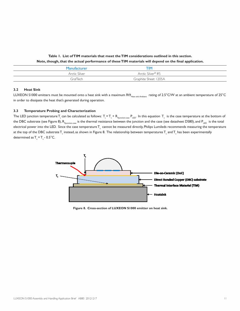
3.3 Temperature Probing and Characterization
The LED junction temperature Tj can be calculated as follows: Tj = Tc + Rujunction-case PLED. In this equation Tc is the case temperature at the bottom of
the DBC substrate (see Figure 8), Rujunction-case is the thermal resistance between the junction and the case (see datasheet DS80), and PLED is the total
electrical power into the LED. Since the case temperature Tc cannot be measured directly, Philips Lumileds recommends measuring the temperature
at the top of the DBC substrate Ts instead, as shown in Figure 8. The relationship between temperatures Tc and Ts has been experimentally
determined as Tc = Ts - 0.5°C.
Figure 8. Cross-section of LUXEON S1000 emitter on heat sink.

LUXEON S1000 Assembly and Handling Application Brief AB80 20121217 12
3.4 Thermal Measurements
This section describes in detail how to mount a thermocouple on the top of the DBC in order to determine the case temperature Tc.
Supplies and Equipment
Below is the list of supplies and equipment that’s needed to Tc measurements:
• TypeTprecisionfinewire(o.oo3”gaugediameter)thermalcouplesfromOmegaEngineeringInc.(partnumber:5SRTC-TT-T-40-36)
• Eccobondonecomponent,lowtemperaturecuring,thermalconductiveepoxyadhesivefromEmersonandCuming(partnumber:E3503-1)
or Arctic Alumina Thermal Adhesive compound from Arctic Silver Inc. (part number: AATA-5G)
• Disposable3CCbarrelsyringefromEFDInc.(partnumber5109LL-B)
• Disposable0.016”innerdiameterfineneedletipfromEFCInc.(partnumber:5122-B)
• Kaptontape
• Convectionoven(forcuringofEccobondepoxy)
• Thermometer
• Magnifyingglassorlowpowermicroscope(e.g.5xto30x)
Thermocouple mounting procedure
1. Familiarize yourself with the manufacturer’s Material Safety Data Sheet (MSDS) and preparation procedures for the epoxy or adhesive
compound.
2. PlacethethermocoupletipwithintheareadefinedinFigure9.Thethermocouplemusttouchthegoldpadwithinthisareainordertoavoid
any interference with the contact points of the LUXEON S1000 Mechanical Clamp and to ensure accurate measurements.
3. UsetheKaptontapetosecurethethermocouplewireontheLUXEONS1000emitter.
4. Follow step a or b depending on the compound or adhesive that’s used to thermally connect the thermocouple to the thermal pad on the top
of the DBC
a. Eccobond Thermal Adhesive Epoxy
i. Thaw the thermal conductive epoxy per manufacturer’s recommendations.
ii. Dispense sufficient epoxy into the 3CC barrel syringe with the fine needle tip. Store the balance per manufacturer’s
recommendations.
iii. DropasmallamountofthermalconductiveepoxyjustenoughtocoverthethermocoupletipasshowninFigure9.
iv. Cure the epoxy per the manufacturer’s recommendations. Make sure that the oven temperature does not exceed the maximum
rated temperature of the LUXEON S1000 emitter.
v. Let the board cool down to room temperature before starting any measurements.

LUXEON S1000 Assembly and Handling Application Brief AB80 20121217 13
b. Arctic Alumina Thermal Adhesive compound
i. Since this is a two part epoxy system with an approximate pot-life at room temperature after mixing of 3-4 minutes, make sure that
proper setup is done to ensure that the epoxy can be dispensed within the pot-life span.
ii. After mixing, put the epoxy immediately into the 3CC barrel syringe with the fine needle tip and dispense onto the thermocouple
tip. Close to the end of the pot-life, it becomes difficult to dispense.
iii. Alternately,youcandipthefineneedletipintotheepoxymixandthen“touch”thethermocoupletiptodispensetheepoxyvia
surface tension.
iv. Cure the epoxy at room temperature (25°C) for at least two hours.
5. Once the epoxy/compound has hardened, the LUXEON S1000 emitter with thermocouple should be mounted onto the heat sink with the
Solderless LED Socket. If necessary, make a small groove in the Solderless LED Socket to prevent the thermocouple from getting pinched
between the heat sink and the clamp (Figure 10).
6. Plug in the thermocouple connector to the thermometer. The thermocouple now measures the temperature at the top of the DBC (Ts).
7. Connect the power supply and light up the LUXEON S1000 emitter with a drive current that corresponds to normal operating conditions.
If possible, attach all fixtures (e.g. clamp on heat sink, lens and any cover) to closely simulate the actual application environment.
8. Record the temperature Ts at the top of the DBC until it stabilizes. This may take a minute or more depending on the overall thermal design.
9. Thecasetemperaturecanthenbeestimatedasfollows:Tc = Ts - 0.5°C.
Figure 9. Thermal contact area highlighted in red (left) and example of TC probe attachment (right).

LUXEON S1000 Assembly and Handling Application Brief AB80 20121217 14
4. Product Packaging Considerations – Chemical CompatibilityThe LUXEON S1000 package contains a silicone overcoat and dome to protect the LED chips and extract the maximum amount of light. As with
most silicones used in LED optics, care must be taken to prevent any incompatible chemicals from directly or indirectly reacting with the silicone.
The silicone overcoat in LUXEON S1000 is gas permeable. Consequently, oxygen and volatile organic compound (VOC) gas molecules can diffuse
into the silicone overcoat. VOCs may originate from adhesives, solder fluxes, conformal coating materials, potting materials and even some of the
inks that are used to print the PCBs.
Some VOCs and chemicals react with silicone and produce discoloration and surface damage. Other VOCs do not chemically react with the silicone
material directly but diffuse into the silicone and oxidize during the presence of heat or light. Regardless of the physical mechanism, both cases may
affect the total LED light output. Since silicone permeability increases with temperature, more VOCs may diffuse into and/or evaporate out from
the silicone.
CarefulconsiderationmustbegiventowhetherLUXEONS1000emittersareenclosedinan“airtight”environmentornot.Inan“airtight”
environment,someVOCsthatwereintroducedduringassemblymaypermeateandremaininthesiliconedome.Underheatand“blue”light,the
VOCs inside the dome may partially oxidize and create a silicone discoloration, particularly on the surface of the LED where the flux energy is the
highest.Inanairrichor“open”airenvironment,VOCshaveachancetoleavethearea(drivenbythenormalairflow).Transferringthedevices
whichwerediscoloredintheenclosedenvironmentbackto“open”airmayallowtheoxidizedVOCstodiffuseoutofthesiliconedomeandmay
restore the original optical properties of the LED.
Determining suitable threshold limits for the presence of VOCs is very difficult since these limits depend on the type of enclosure used to house
the LEDs and the operating temperatures. Also, some VOCs can photo-degrade over time.
Figure 10. A small groove in the Solderless LED Socket, Type LS prevents the thermocouple
from being pinched between the clamp and the heat sink.

LUXEON S1000 Assembly and Handling Application Brief AB80 20121217 15
Table 2 provides a list of commonly used chemicals that should be avoided as they may react with the silicone material. Note that Philips Lumileds
does not warrant that this list is exhaustive since it is impossible to determine all chemicals that may affect LED performance.
The chemicals in Table 2 are typically not directly used in the final products that are built around LUXEON S1000 LEDs. However, some of these
chemicals may be used in intermediate manufacturing steps (e.g. cleaning agents). Consequently, trace amounts of these chemicals may remain
on (sub)components, such heat sinks. Philips Lumileds, therefore, recommends the following precautions when designing your application:
- WhendesigningsecondarylensestobeusedoverasingleLED,provideasufficientlylargeair-pocketandallowfor“ventilation”ofthisair
away from the immediate vicinity of the LED.
- Use mechanical means of attaching lenses and circuit boards as much as possible. When using adhesives, potting compounds and coatings,
carefully analyze its material composition and do thorough testing of the entire fixture under High Temperature over Life (HTOL) conditions.
Table 2. List of commonly used chemicals that will damage the silicone dome of LUXEON S1000.
Avoid using any of these chemicals in the housing that contains the LED package.
Chemical Name Normally used as hydrochloric acid acid
sulfuric acid acid
nitric acid acid
acetic acid acid
sodium hydroxide alkali
potassium hydroxide alkali
ammonia alkali
MEK (Methyl Ethyl Ketone) solvent
MIBK (Methyl Isobutyl Ketone) solvent
Toluene solvent
Xylene solvent
Benzene solvent
Gasoline solvent
Mineral spirits solvent
dichloromethane solvent
tetracholorometane solvent
Castor oil oil
lard oil
linseed oil oil
petroleum oil
silicone oil oil
halogenated hydrocarbons (containing F, Cl, Br elements) misc
rosin flux solder flux
acrylic tape adhesive

DisclaimerProvided as-is for informational purposes only. This is not a warranty or specification. Subject to change without notice.
Company Information
©2012 Philips Lumileds Lighting Company. All rights reserved. Product specifications are subject to change without notice.
www.philipslumileds.com
www.philipslumileds.cn.com
Philips Lumileds is a leading provider of LEDs for everyday lighting applications. The company’s records for light output,
efficacy and thermal management are direct results of the ongoing commitment to advancing solid-state lighting technology
and enabling lighting solutions that are more environmentally friendly, help reduce CO2 emissions and reduce the need for
power plant expansion. Philips Lumileds LUXEON® LEDs are enabling never before possible applications in outdoor lighting,
shop lighting, home lighting, consumer electronics, and automotive lighting.
Philips Lumileds is a fully integrated supplier, producing core LED material in all three base colors, (Red, Green, Blue) and
white. Philips Lumileds has R&D centers in San Jose, California and in the Netherlands, and production capabilities in
San Jose, Singapore and Penang, Malaysia. Founded in 1999, Philips Lumileds is the high flux LED technology leader and is
dedicated to bridging the gap between solid-state technology and the lighting world. More information about the company’s
LUXEON LED products and solid-state lighting technologies can be found at www.philipslumileds.com.