Luminary ALIF. Disc preparation and implant …synthes.vo.llnwd.net/o16/Mobile/Synthes North...
25
Luminary ALIF. Disc preparation and implant insertion instruments. Technique Guide Instruments and implants approved by the AO Foundation
Transcript of Luminary ALIF. Disc preparation and implant …synthes.vo.llnwd.net/o16/Mobile/Synthes North...
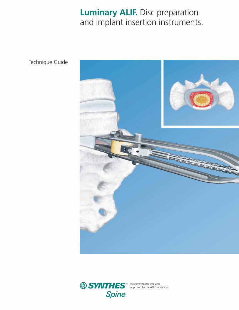
Luminary ALIF. Disc preparation and implant insertion instruments.
Technique Guide
Instruments and implants approved by the AO Foundation
Table of Contents
Image intensifier control
Synthes Spine
Introduction
Surgical Technique
Product Information
Luminary ALIF 2
AO Principles 4
Preparation 5
Straight Anterior Approach 6
Anterolateral Approach (30º Offset) 16
Instruments 18
Set Lists 21
Luminary ALIF
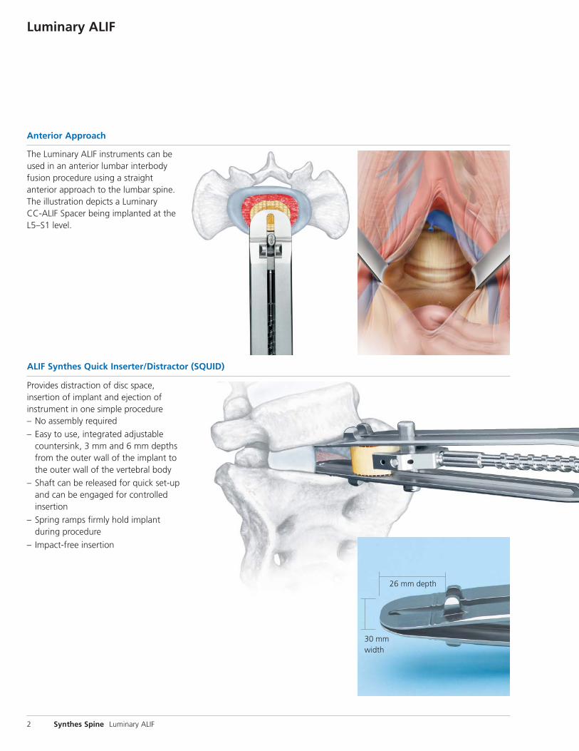
Anterior Approach
The Luminary ALIF instruments can beused in an anterior lumbar interbody fusion procedure using a straight anterior approach to the lumbar spine.The illustration depicts a Luminary CC-ALIF Spacer being implanted at theL5–S1 level.
Provides distraction of disc space, insertion of implant and ejection of instrument in one simple procedure– No assembly required
– Easy to use, integrated adjustable countersink, 3 mm and 6 mm depthsfrom the outer wall of the implant tothe outer wall of the vertebral body
– Shaft can be released for quick set-upand can be engaged for controlled insertion
– Spring ramps firmly hold implant during procedure
– Impact-free insertion
2 Synthes Spine Luminary ALIF
ALIF Synthes Quick Inserter/Distractor (SQUID)
26 mm depth
30 mmwidth
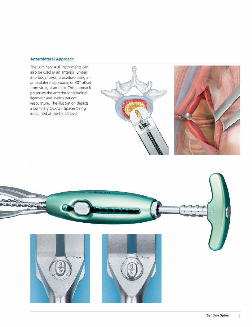
6 mm
Synthes Spine 3
Anterolateral Approach
The Luminary ALIF instruments can also be used in an anterior lumbar interbody fusion procedure using an anterolateral approach, or 30° offsetfrom straight anterior. This approachpreserves the anterior longitudinal ligament and avoids patient vasculature. The illustration depicts a Luminary CC-ALIF Spacer being implanted at the L4–L5 level.
3 mm
AO Principles
In 1958, the AO formulated four basic principles,1 which havebecome the guidelines for internal fixation. They are:
– Anatomic reduction– Stable internal fixation– Preservation of blood supply– Early, active mobilization
The fundamental aims of fracture treatment in the limbs andfusion of the spine are the same. A specific goal in the spine is returning as much function as possible to the injured neural elements.2
AO Principles as Applied to the Spine3
Anatomic alignmentRestoration of normal spinal alignment to improve the biomechanics of the spine.
Stable internal fixationStabilization of the spinal segment to promote bony fusion.
Preservation of blood supplyCreation of an optimal environment for fusion.
Early, active mobilizationMinimization of damage to the spinal vasculature, dura, andneural elements, which may contribute to pain reduction andimproved function for the patient.
4 Synthes Spine Luminary ALIF
1. M.E. Müller, M. Allgöwer, R. Schneider, H. Willenegger: AO Manual of InternalFixation, 3rd Edition. Berlin: Springer-Verlag. 1991.2. Ibid.3. M. Aebi, J.S. Thalgott, J.K. Webb. AO ASIF Principles in Spine Surgery. Berlin:Springer-Verlag. 1998.
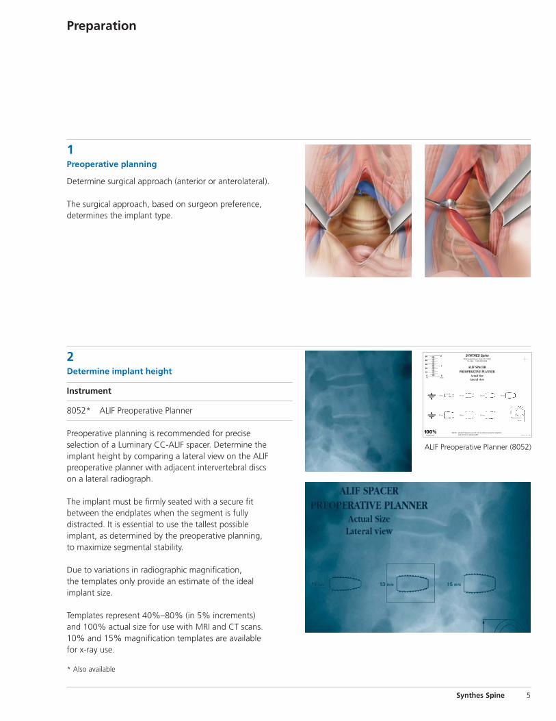
1Preoperative planning
Determine surgical approach (anterior or anterolateral).
The surgical approach, based on surgeon preference, determines the implant type.
2Determine implant height
Instrument
8052* ALIF Preoperative Planner
Preoperative planning is recommended for precise selection of a Luminary CC-ALIF spacer. Determine the implant height by comparing a lateral view on the ALIF preoperative planner with adjacent intervertebral discs on a lateral radiograph.
The implant must be firmly seated with a secure fit between the endplates when the segment is fully distracted. It is essential to use the tallest possible implant, as determined by the preoperative planning, to maximize segmental stability.
Due to variations in radiographic magnification, the templates only provide an estimate of the ideal implant size.
Templates represent 40%–80% (in 5% increments) and 100% actual size for use with MRI and CT scans. 10% and 15% magnification templates are available for x-ray use.
Synthes Spine 5
Preparation
SYNTHES Spine1690 Russell Road, Paoli, PA 19301
To order: 1-800-522-9069
ALIF SPACERPREOPERATIVE PLANNER
Actual SizeLateral view
GP1739-A 3/01 J3554
100%actual size
NOTE: All ALIF Spacers are 24 mm in anterior-posterior directionand 30 mm in lateral width.
ANTERIORHEIGHT
ANTERIORHEIGHT
50
40
30
20
10
0
2
1
0 mm Inches
9 mm 11 mm 13 mm 15 mm
17 mm 19 mm 21 mm
24 mm
30m
m
ALIF Preoperative Planner (8052)
* Also available
Straight Anterior Approach
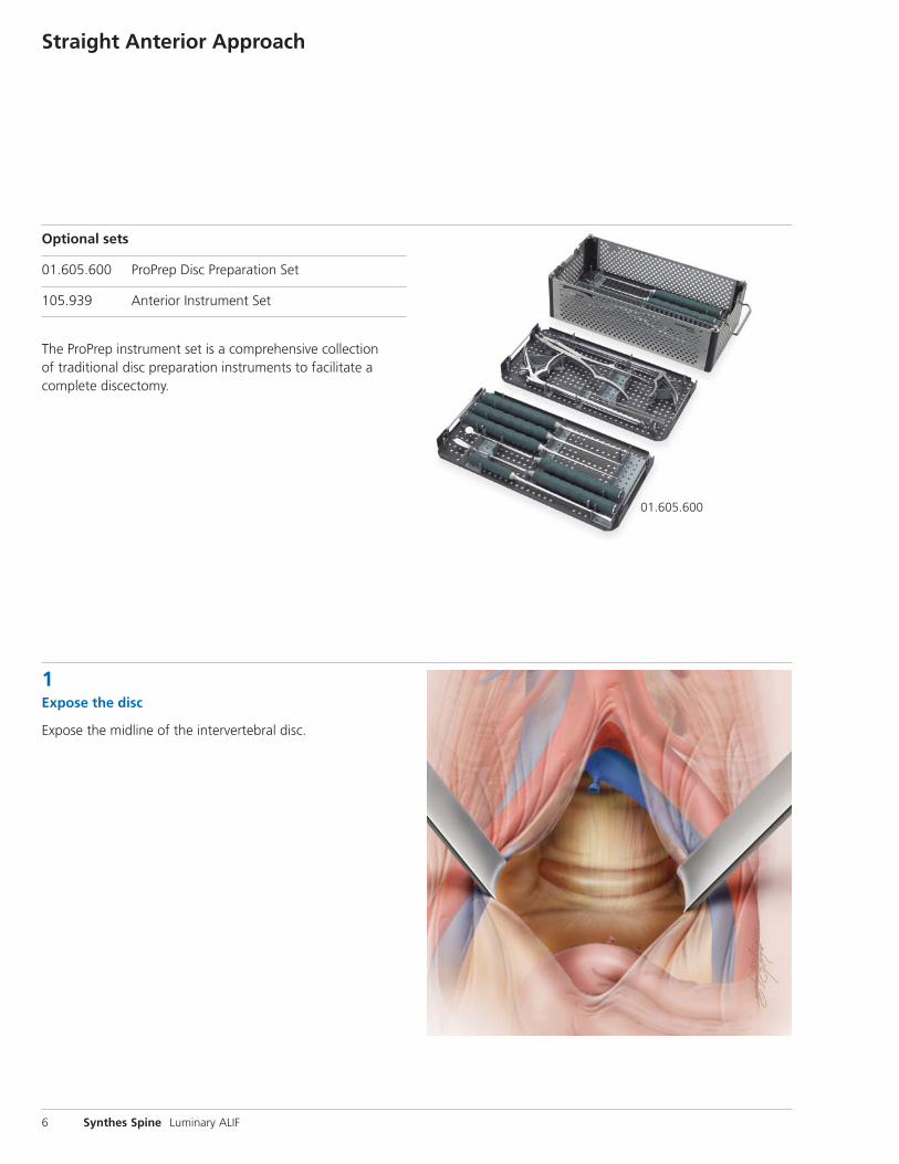
Optional sets
01.605.600 ProPrep Disc Preparation Set
105.939 Anterior Instrument Set
The ProPrep instrument set is a comprehensive collection of traditional disc preparation instruments to facilitate acomplete discectomy.
1Expose the disc
Expose the midline of the intervertebral disc.
6 Synthes Spine Luminary ALIF
01.605.600
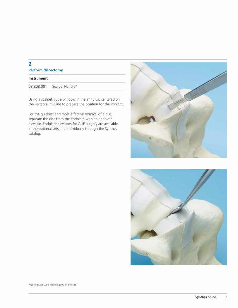
2Perform discectomy
Instrument
03.808.001 Scalpel Handle*
Using a scalpel, cut a window in the annulus, centered onthe vertebral midline to prepare the position for the implant.
For the quickest and most effective removal of a disc, separate the disc from the endplate with an endplate elevator. Endplate elevators for ALIF surgery are available in the optional sets and individually through the Synthes catalog.
Synthes Spine 7
*Note: Blades are not included in the set.
Straight Anterior Approach continued
2Perform discectomy continued
Instruments
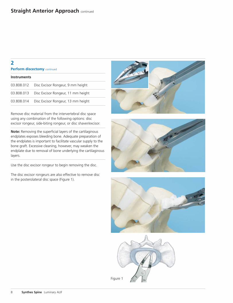
03.808.012 Disc Excisor Rongeur, 9 mm height
03.808.013 Disc Excisor Rongeur, 11 mm height
03.808.014 Disc Excisor Rongeur, 13 mm height
Remove disc material from the intervertebral disc space using any combination of the following options: disc excisor rongeur, side-biting rongeur, or disc shaver/excisor.
Note: Removing the superficial layers of the cartilaginousendplates exposes bleeding bone. Adequate preparation ofthe endplates is important to facilitate vascular supply to thebone graft. Excessive cleaning, however, may weaken theendplate due to removal of bone underlying the cartilaginouslayers.
Use the disc excisor rongeur to begin removing the disc.
The disc excisor rongeurs are also effective to remove disc in the posterolateral disc space (Figure 1).
8 Synthes Spine Luminary ALIF
Figure 1
Instruments
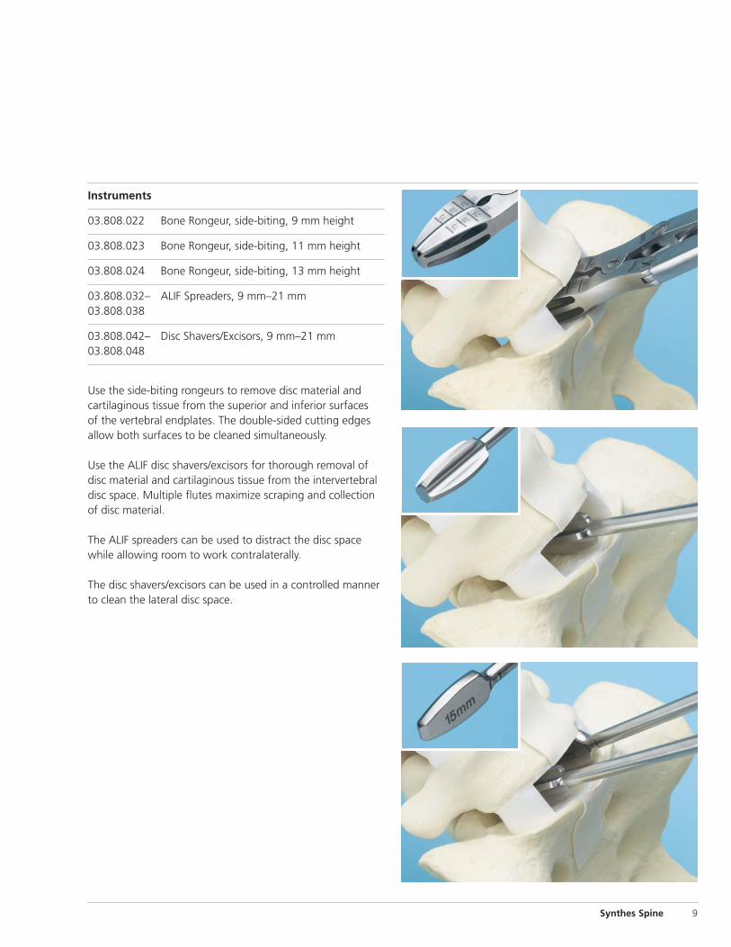
03.808.022 Bone Rongeur, side-biting, 9 mm height
03.808.023 Bone Rongeur, side-biting, 11 mm height
03.808.024 Bone Rongeur, side-biting, 13 mm height
03.808.032– ALIF Spreaders, 9 mm–21 mm03.808.038
03.808.042– Disc Shavers/Excisors, 9 mm–21 mm03.808.048
Use the side-biting rongeurs to remove disc material and cartilaginous tissue from the superior and inferior surfaces of the vertebral endplates. The double-sided cutting edgesallow both surfaces to be cleaned simultaneously.
Use the ALIF disc shavers/excisors for thorough removal ofdisc material and cartilaginous tissue from the intervertebraldisc space. Multiple flutes maximize scraping and collectionof disc material.
The ALIF spreaders can be used to distract the disc spacewhile allowing room to work contralaterally.
The disc shavers/excisors can be used in a controlled mannerto clean the lateral disc space.
Synthes Spine 9
Straight Anterior Approach continued
3Prepare endplates
Instrument
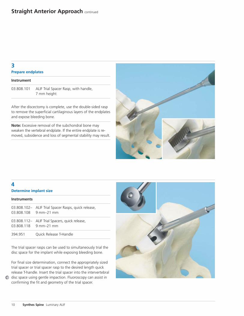
03.808.101 ALIF Trial Spacer Rasp, with handle, 7 mm height
After the discectomy is complete, use the double-sided raspto remove the superficial cartilaginous layers of the endplatesand expose bleeding bone.
Note: Excessive removal of the subchondral bone mayweaken the vertebral endplate. If the entire endplate is re-moved, subsidence and loss of segmental stability may result.
4Determine implant size
Instruments
03.808.102– ALIF Trial Spacer Rasps, quick release, 03.808.108 9 mm–21 mm
03.808.112– ALIF Trial Spacers, quick release, 03.808.118 9 mm–21 mm
394.951 Quick Release T-Handle
The trial spacer rasps can be used to simultaneously trial thedisc space for the implant while exposing bleeding bone.
For final size determination, connect the appropriately sizedtrial spacer or trial spacer rasp to the desired length quick release T-handle. Insert the trial spacer into the intervertebraldisc space using gentle impaction. Fluoroscopy can assist inconfirming the fit and geometry of the trial spacer.
10 Synthes Spine Luminary ALIF
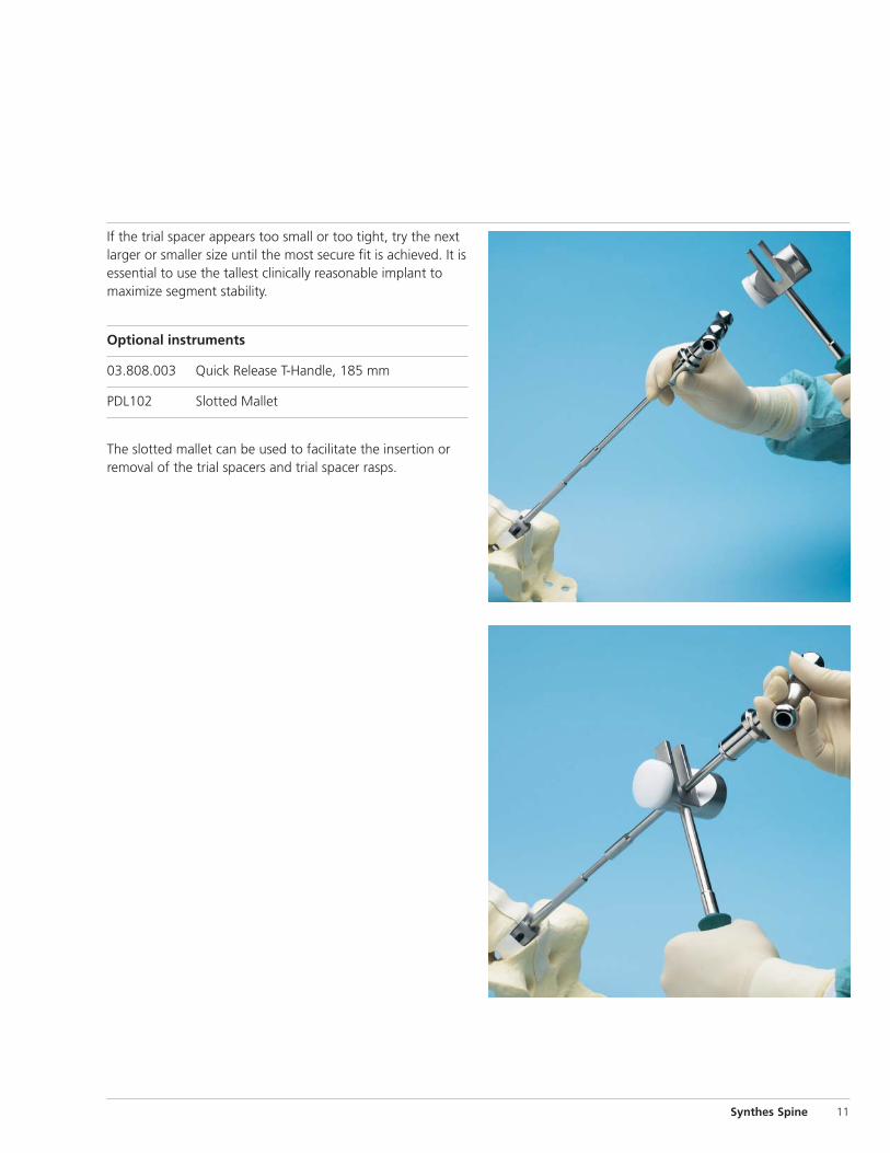
If the trial spacer appears too small or too tight, try the nextlarger or smaller size until the most secure fit is achieved. It is essential to use the tallest clinically reasonable implant tomaximize segment stability.
Optional instruments
03.808.003 Quick Release T-Handle, 185 mm
PDL102 Slotted Mallet
The slotted mallet can be used to facilitate the insertion or removal of the trial spacers and trial spacer rasps.
Synthes Spine 11
Straight Anterior Approach continued
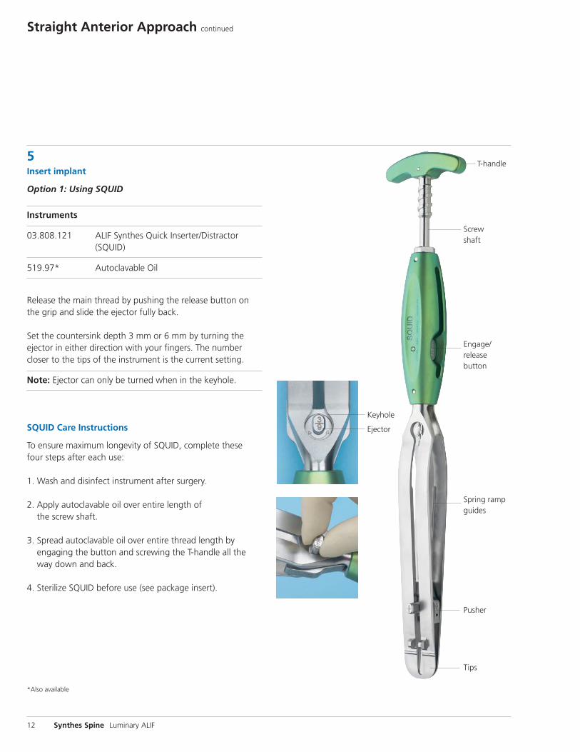
5Insert implant
Option 1: Using SQUID
Instruments
03.808.121 ALIF Synthes Quick Inserter/Distractor(SQUID)
519.97* Autoclavable Oil
Release the main thread by pushing the release button onthe grip and slide the ejector fully back.
Set the countersink depth 3 mm or 6 mm by turning theejector in either direction with your fingers. The numbercloser to the tips of the instrument is the current setting.
Note: Ejector can only be turned when in the keyhole.
SQUID Care Instructions
To ensure maximum longevity of SQUID, complete these four steps after each use:
1. Wash and disinfect instrument after surgery.
2. Apply autoclavable oil over entire length of the screw shaft.
3. Spread autoclavable oil over entire thread length by engaging the button and screwing the T-handle all theway down and back.
4. Sterilize SQUID before use (see package insert).
12 Synthes Spine Luminary ALIF
Engage/release button
Spring rampguides
Pusher
Tips
T-handle
Screwshaft
Keyhole
Ejector
*Also available
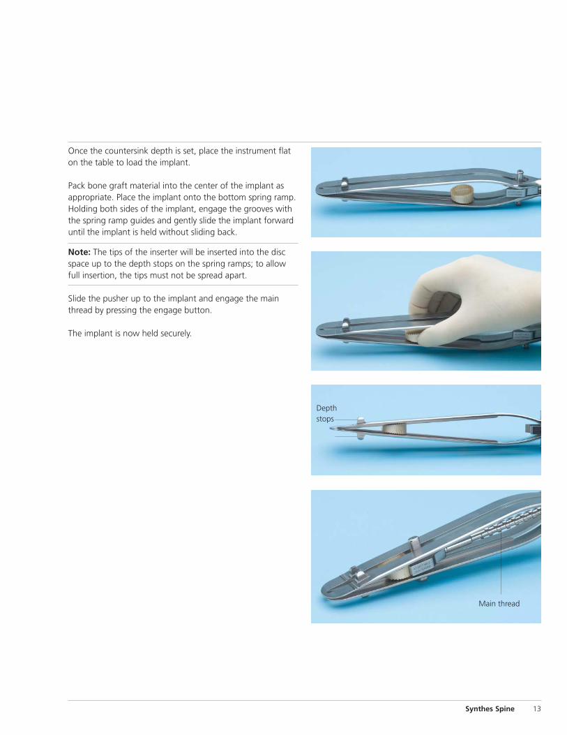
Once the countersink depth is set, place the instrument flaton the table to load the implant.
Pack bone graft material into the center of the implant asappropriate. Place the implant onto the bottom spring ramp.Holding both sides of the implant, engage the grooves withthe spring ramp guides and gently slide the implant forwarduntil the implant is held without sliding back.
Note: The tips of the inserter will be inserted into the discspace up to the depth stops on the spring ramps; to allowfull insertion, the tips must not be spread apart.
Slide the pusher up to the implant and engage the mainthread by pressing the engage button.
The implant is now held securely.
Synthes Spine 13
Depthstops
Main thread
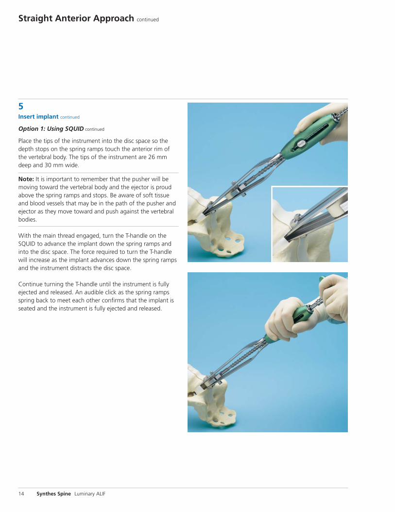
Straight Anterior Approach continued
5Insert implant continued
Option 1: Using SQUID continued
Place the tips of the instrument into the disc space so thedepth stops on the spring ramps touch the anterior rim ofthe vertebral body. The tips of the instrument are 26 mmdeep and 30 mm wide.
Note: It is important to remember that the pusher will bemoving toward the vertebral body and the ejector is proudabove the spring ramps and stops. Be aware of soft tissue and blood vessels that may be in the path of the pusher andejector as they move toward and push against the vertebralbodies.
With the main thread engaged, turn the T-handle on theSQUID to advance the implant down the spring ramps andinto the disc space. The force required to turn the T-handlewill increase as the implant advances down the spring rampsand the instrument distracts the disc space.
Continue turning the T-handle until the instrument is fullyejected and released. An audible click as the spring rampsspring back to meet each other confirms that the implant isseated and the instrument is fully ejected and released.
14 Synthes Spine Luminary ALIF
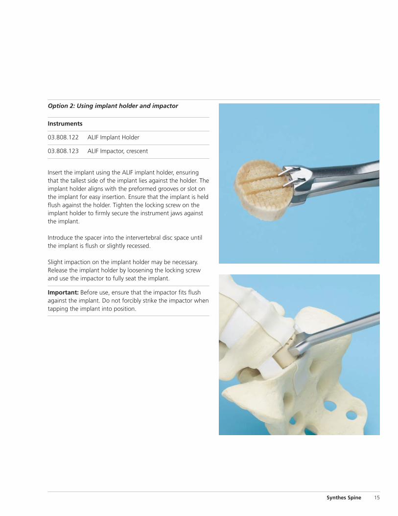
Option 2: Using implant holder and impactor
Instruments
03.808.122 ALIF Implant Holder
03.808.123 ALIF Impactor, crescent
Insert the implant using the ALIF implant holder, ensuringthat the tallest side of the implant lies against the holder. Theimplant holder aligns with the preformed grooves or slot onthe implant for easy insertion. Ensure that the implant is heldflush against the holder. Tighten the locking screw on theimplant holder to firmly secure the instrument jaws againstthe implant.
Introduce the spacer into the intervertebral disc space untilthe implant is flush or slightly recessed.
Slight impaction on the implant holder may be necessary. Release the implant holder by loosening the locking screwand use the impactor to fully seat the implant.
Important: Before use, ensure that the impactor fits flushagainst the implant. Do not forcibly strike the impactor whentapping the implant into position.
Synthes Spine 15
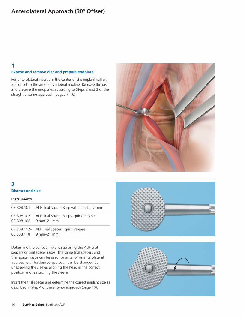
Anterolateral Approach (30° Offset)
1Expose and remove disc and prepare endplate
For anterolateral insertion, the center of the implant will sit30° offset to the anterior vertebral midline. Remove the discand prepare the endplates according to Steps 2 and 3 of thestraight anterior approach (pages 7–10).
2Distract and size
Instruments
03.808.101 ALIF Trial Spacer Rasp with handle, 7 mm
03.808.102– ALIF Trial Spacer Rasps, quick release, 03.808.108 9 mm–21 mm
03.808.112– ALIF Trial Spacers, quick release, 03.808.118 9 mm–21 mm
Determine the correct implant size using the ALIF trial spacers or trial spacer rasps. The same trial spacers and trial spacer rasps can be used for anterior or anterolateral approaches. The desired approach can be changed by unscrewing the sleeve, aligning the head in the correct position and reattaching the sleeve.
Insert the trial spacer and determine the correct implant size asdescribed in Step 4 of the anterior approach (page 10).
16 Synthes Spine Luminary ALIF
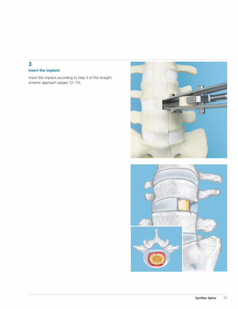
3Insert the implant
Insert the implant according to Step 5 of the straight anterior approach (pages 12–15).
Synthes Spine 17
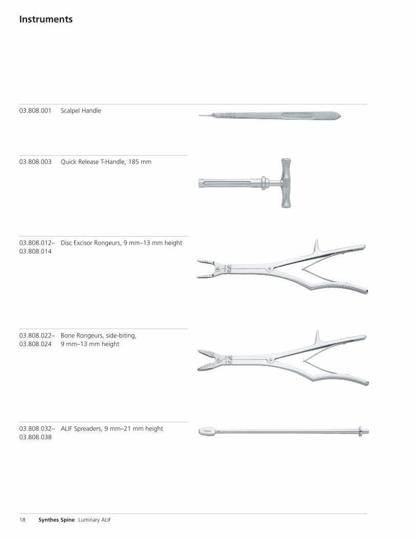
Instruments
03.808.001 Scalpel Handle
03.808.003 Quick Release T-Handle, 185 mm
03.808.012– Disc Excisor Rongeurs, 9 mm–13 mm height03.808.014
03.808.022– Bone Rongeurs, side-biting, 03.808.024 9 mm–13 mm height
03.808.032– ALIF Spreaders, 9 mm–21 mm height03.808.038
18 Synthes Spine Luminary ALIF
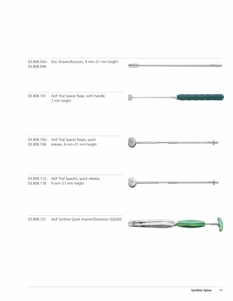
03.808.102– ALIF Trial Spacer Rasps, quick 03.808.108 release, 9 mm–21 mm height
03.808.112– ALIF Trial Spacers, quick release,03.808.118 9 mm–21 mm height
03.808.121 ALIF Synthes Quick Inserter/Distractor (SQUID)
03.808.042– Disc Shavers/Excisors, 9 mm–21 mm height03.808.048
03.808.101 ALIF Trial Spacer Rasp, with handle, 7 mm height
Synthes Spine 19
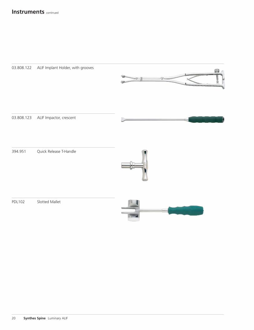
Instruments continued
20 Synthes Spine Luminary ALIF
03.808.122 ALIF Implant Holder, with grooves
03.808.123 ALIF Impactor, crescent
394.951 Quick Release T-Handle
PDL102 Slotted Mallet
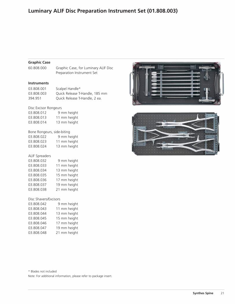
Luminary ALIF Disc Preparation Instrument Set (01.808.003)
Graphic Case
60.808.000 Graphic Case, for Luminary ALIF Disc Preparation Instrument Set
Instruments
03.808.001 Scalpel Handle*03.808.003 Quick Release T-Handle, 185 mm394.951 Quick Release T-Handle, 2 ea.
Disc Excisor Rongeurs03.808.012 9 mm height03.808.013 11 mm height 03.808.014 13 mm height
Bone Rongeurs, side-biting 03.808.022 9 mm height03.808.023 11 mm height03.808.024 13 mm height
ALIF Spreaders03.808.032 9 mm height03.808.033 11 mm height03.808.034 13 mm height03.808.035 15 mm height03.808.036 17 mm height03.808.037 19 mm height03.808.038 21 mm height
Disc Shavers/Excisors 03.808.042 9 mm height03.808.043 11 mm height03.808.044 13 mm height03.808.045 15 mm height03.808.046 17 mm height03.808.047 19 mm height03.808.048 21 mm height
Synthes Spine 21
* Blades not included
Note: For additional information, please refer to package insert.
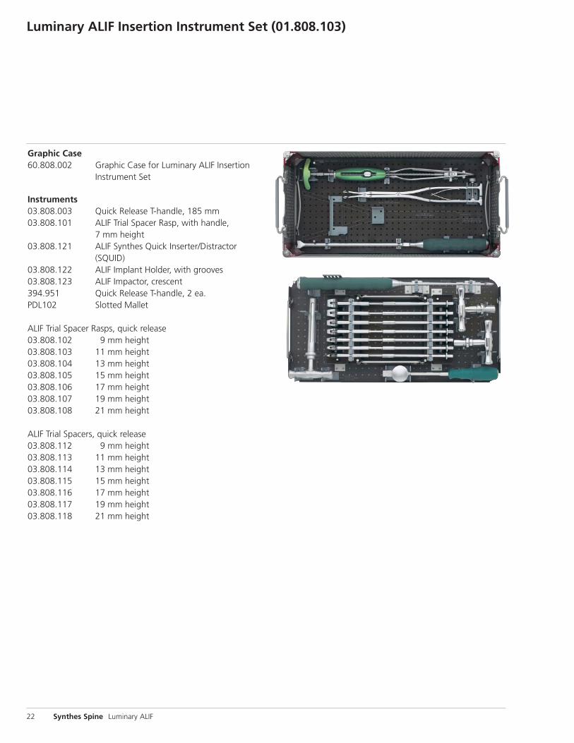
Luminary ALIF Insertion Instrument Set (01.808.103)
22 Synthes Spine Luminary ALIF
Graphic Case60.808.002 Graphic Case for Luminary ALIF Insertion
Instrument Set
Instruments03.808.003 Quick Release T-handle, 185 mm03.808.101 ALIF Trial Spacer Rasp, with handle,
7 mm height03.808.121 ALIF Synthes Quick Inserter/Distractor
(SQUID)03.808.122 ALIF Implant Holder, with grooves03.808.123 ALIF Impactor, crescent394.951 Quick Release T-handle, 2 ea.PDL102 Slotted Mallet
ALIF Trial Spacer Rasps, quick release03.808.102 9 mm height03.808.103 11 mm height 03.808.104 13 mm height03.808.105 15 mm height03.808.106 17 mm height03.808.107 19 mm height03.808.108 21 mm height
ALIF Trial Spacers, quick release03.808.112 9 mm height03.808.113 11 mm height 03.808.114 13 mm height03.808.115 15 mm height03.808.116 17 mm height03.808.117 19 mm height03.808.118 21 mm height
Also Available
Optional Sets01.605.600 ProPrep Disc Preparation Set105.939 Anterior Instrument Set
InstrumentsDisc Excisor Rongeurs03.808.011 7 mm height03.808.015 15 mm height 03.808.016 17 mm height03.808.017 19 mm height 03.808.018 21 mm height
Bone Rongeurs, side-biting 03.808.025 15 mm height03.808.026 17 mm height03.808.027 19 mm height03.808.028 21 mm height
8052 ALIF Preoperative Planner
Synthes Spine 23

Synthes Spine1302 Wrights Lane EastWest Chester, PA 19380Telephone: (610) 719-5000To order: (800) 523-0322Fax: (610) 251-9056
Synthes (Canada) Ltd.2566 Meadowpine BoulevardMississauga, Ontario L5N 6P9Telephone: (905) 567-0440To order: (800) 668-1119Fax: (905) 567-3185
© 2006 Synthes, Inc. or its affiliates. All rights reserved. ProPrep and Synthes are trademarks of Synthes, Inc or its affiliates. Printed in U.S.A. 8/08 J6782-B
www.synthes.com