Luisel Zayas Wes McGee Quarra Cairn -...
10
650 Quarra Cairn 1 Full-scale prototype on site at Quarra Stone Company, LLC: Madison, Wisconsin, 2015. Wes McGee University of Michigan, Maer Design James Durham Quarra Stone Company, LLC Luisel Zayas Massachuses Instute of Technology Dusn Brugmann University of Michigan Brandon Clifford Massachuses Instute of Technology, Maer Design 1 ABSTRACT Recent advances in integrang physical logic into computaon strategies have brought the master- makers mentality back to the forefront of the digital era, yet a long-standing problem persists: ongoing efforts to develop reciprocal structures with gravitaonal forces tend to generate forms that are unable to be constructed without massive falsework. This paper explores the potenal to intelligently remove material from the interior of a column drum in order to produce a leaning column that could contribute to solving this age-old problem. The paper describes the computaon and fabricaon logic required, then demonstrates a full-scale prototype and some of the discoveries that emerged as a result of the computaon process. Incremental Stability Through Shiſting and Removal of Mass
-
Upload
hoangquynh -
Category
Documents
-
view
216 -
download
0
Transcript of Luisel Zayas Wes McGee Quarra Cairn -...

650
Quarra Cairn
1 Full-scale prototype on site at Quarra Stone Company, LLC: Madison, Wisconsin, 2015.
Wes McGeeUniversity of Michigan, Matter Design
James DurhamQuarra Stone Company, LLC
Luisel ZayasMassachusetts Institute of Technology
Dustin Brugmann University of Michigan
Brandon CliffordMassachusetts Institute of Technology, Matter Design
1
ABSTRACTRecent advances in integrating physical logic into computation strategies have brought the master-makers mentality back to the forefront of the digital era, yet a long-standing problem persists: ongoing efforts to develop reciprocal structures with gravitational forces tend to generate forms that are unable to be constructed without massive falsework. This paper explores the potential to intelligently remove material from the interior of a column drum in order to produce a leaning column that could contribute to solving this age-old problem. The paper describes the computation and fabrication logic required, then demonstrates a full-scale prototype and some of the discoveries that emerged as a result of the computation process.
Incremental Stability Through Shifting and Removal of Mass

651ACADIA 2017 | DISCIPLINES + DISRUPTION
INTRODUCTIONThough it is commonly assumed Antoni Gaudí employed a "hanging chain" method to design La Sagrada Familia, the famous image of the sandbag laden inverted chain model is actually of Colònia Güell, a partially realized project (Burry 2007; Huerta 2013). While Gaudí developed this method prior to the construc-tion of La Sagrada Familia, it was not implemented because of a fatal flaw in this strategy. The hanging chain model prioritizes an optimized load path to the ground. The flaw in this noble struc-ture is that in order to become structurally stable, the building needs to exist in its entirety, making it impossible to build without a massively wasteful system of centering and falsework. A clear distinction is manifest in the two projects. While Colònia Güell's columns buttress the forces at angles, La Sagrada Familia reverts to the more typical vertical column. As it turns out, it is quite difficult to support a leaning column while the mass above is still being constructed. The intelligence of funicular geometry is brilliant in its complete state, but the problem of incremental stability throughout the construction process presents a signifi-cant challenge.
While Gaudí pioneered this reciprocity between form and force, other researchers such as Frei Otto have continued this line of inquiry (Rasch and Otto 1996). A paper translated this methodology into digital procedures and The Block Research Group is currently continuing the fight to bend thrust through matter (Kilian and Ochsendorf 2005). A recent work titled "The Armadillo Vault" demonstrates the most recent advances they have made in creating computational techniques that integrate form and force. This work also exemplifies the same issue that Gaudí faced with stability throughout the assembly process. This vault is constructed on a custom falsework consisting of standard scaffolding towers that support four marine-grade plywood waffle structures (Block et al. 2016). The need for falsework in such a project is a minor conceit; however, the necessity for falsework can derive complications at scale, when doubling the geometry, or if attempting to span something that cannot bear weight. Recent research has investigated methods for casting metal details to incrementally support voussoirs in space throughout the assembly process to contribute to these efforts (Ariza et al. 2016).
Is it possible to remove material from the interior of a column drum in order to ensure stability? Asymmetrical stability by means of mass distribution and interior hollowing has also been explored in spinning objects (Bächer et al. 2013). As a case study, a column is designed in such a manner that it cannot stand—similar to Gaudí's leaning column—without the aid of external support, or in this case, the removal of material. This paper
2
2 Comparison of computation methods: Mass Carving vs Shape Deformation.
describes the computation and fabrication of a non-idealized column that maintains an equilibrium state during assembly.
Definition of TermsAn object is in balance if its center of gravity is above its base of support. The average position of an object's weight distribution is called the center of gravity (COG). For simple, solid objects, such as a sphere or a cube, the center of gravity is located at the geometric center. If an object does not have a uniform weight distribution, then the center of gravity will be closer to where most of the weight is located. The average position of an object's mass or matter distribution is called the center of mass (COM). The point where the line of gravity touches the ground is called the center of pressure. An object is balanced if the center of pressure is inside the base support. When there is more than one area of contact, the base of support is the area inside the perimeter. The line of gravity is an imaginary vertical line that extends upward and downward from the center of gravity. Falsework is framing structure necessary to temporarily support an assembly during the construction process.
COMPUTATIONThe intent of this research is to stabilize a stone structure by shifting its center of mass. For this purpose, a non-stable volume was generated (Figure 2). The input geometry is derived from a polygonal control point rig to produce a calculus-based curvature continuous surface with T-Splines in Rhinoceros.
652
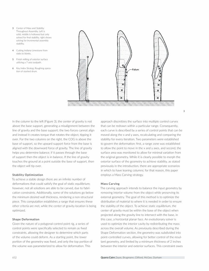
In the column to the left (Figure 3), the center of gravity is not above the base support, generating a misalignment between the line of gravity and the base support; the two forces cannot align and instead it creates torque that rotates the object, tipping it over. For the two columns on the right, the COG is above the base of support, so the upward support force from the base is aligned with the downward force of gravity. The line of gravity helps you determine balance; if it passes through the base of support then the object is in balance. If the line of gravity touches the ground at a point outside the base of support, then the object will tip over.
Stability OptimizationTo achieve a stable design there are an infinite number of deformations that could satisfy the goal of static equilibrium; however, not all solutions are able to be carved, due to fabri-cation constraints. Additionally, some of the solutions go below the minimum desired wall thickness, rendering a non-structural piece. This computation establishes a range that ensures these other criteria are met, while the center of gravity location is being optimized.
Shape DeformationGiven the nature of a polygonal control point rig, a series of control points were specifically selected to remain as fixed constraints, allowing the designer to determine which parts of the volume could deform. As a starting point, the lower portion of the geometry was fixed, and only the top portion of the volume was parameterized to allow for deformation. This
approach discretizes the surface into multiple control curves that can be redrawn within a particular range. Consequently, each curve is described by a series of control points that can be moved along the x and y axes, recalculating and comparing the stability for every iteration. Two parameters were established to govern the deformation: first, a range zone was established to allow the point to move in the x and y axes, and second, the surface area was monitored to allow for minimal variation from the original geometry. While it is clearly possible to morph the exterior surface of the geometry to achieve stability, as stated previously in the introduction, there are appropriate scenarios in which to have leaning columns; for that reason, this paper employs a Mass Carving strategy.
Mass CarvingThe carving approach intends to balance the input geometry by removing interior volume from the object while preserving its external geometry. The goal of this method is to optimize the distribution of material to where it is needed in order to ensure the stability of the object. To achieve static equilibrium, the center of gravity must be within the base of the object when projected along the gravity line to intersect with the base, in this case, a horizontal planar face. An evolutionary solver is used to optimize the interior cavity by redistributing the mass across the overall volume. As previously described during the Shape Deformation section, the geometry was subdivided into point-controlled curves, allowing for better control of the resul-tant geometry, and limited by a minimum thickness of 2 inches between the interior and exterior surfaces. This constraint owes
3 Center of Mass and Stability Throughout Assembly. Left is solid, middle is hollowed but only solved for final stability, right shows solving for incremental assembly stability.
4 Cutting Indiana Limestone from slabs to blanks.
5 Finish milling of exterior surface utilizing a 7-axis toolpath.
6 Key Index Strateg: Roughing opera-tion of stacked drum.
3
Quarra Cairn Zayas, Brugmann, Clifford, McGee, Durham

653ACADIA 2017 | DISCIPLINES + DISRUPTION
4
65
to the material integrity of the selected stone, Indiana Limestone. The volume described by the curves was then subtracted to generate an interior cavity, redistributing the mass to achieve balance.
Incremental StabilityOne of the challenges of fabricating with stone is the substantial weight of the material. Greek builders held tremendous ingenuity with regard to proportioning and discretizing column geome-tries, and the Acropolis is a great example of these techniques. While most of the ongoing research in discrete structures evaluates performance once the assembly process is completed, this research contributes to the effort of computing the static stability of structures during construction by calculating the incremental stability at each step of the stacking process. In a paper titled "Make It Stand," static equilibrium is computed via an interactive solver that carves and deforms as a form-finding driven calculation for 3D-printed objects (Prévost et al. 2013). This research explores solutions to equilibrium at each stage of construction by computing and modifying the center of gravity of individual components.
After satisfying the global stability using the Mass Carving strategy, the next step of the process is to calculate the stability after each of the drums is set in place; for this we needed to take into account the COG of each individual piece and the ones below. In this example, the global geometry is composed of 17 drums, therefore all 17 local centers of gravity produced during the erection of the structure need to rest within the overall
global base support of the geometry. The incremental stability is resolved by feeding the 17 volumes to the fitness criterion while solving for a global line of gravity so that each drum can be carved individually, but remain associated to the rest with the common goal of shifting the global center of pressure deeper into the center of the base. As a result, the drums near the top favor a denser mass opposite the side of the cantilever, almost aligning all the COG in a vertical array; non-external deforma-tions are used to achieve the desirable stable solution.
Evolutionary SolverEvolutionary algorithms, derived from biological evolution, are a series of mathematical operations that approximate solutions to a specific fitness criterion by self-informed mutations. The fitness criterion uses the volume Grasshopper component to calculate the center of gravity for the input geometry and each iteration redefines different x & y values for each curve control point. All the curves then define an interior geometry that is subtracted from the initial geometry, generating a different calculation for the COG. Each of these iterations learns from the previous one, narrowing down the solutions. For the purpose of this research, the optimizer evaluates the stability of the global geometry by measuring the distance between the center of gravity of the column and the centroid of the base on a horizontal plane. The closer the center of gravity is to the centroid of the base, the more stable the global geometry will be.
Once the global geometry in reference to the COG was estab-lished, a series of other parametric Grasshopper scripts were

654
7 Key Joint detail of drums showing the male/female match to ensure rotational equilibrium and stability.
8 Male surface key detail (top) of drum. The key is a parametric offset of the drum face geometry.
9 Filleted drum seam as seen from the column exterior.
10 Global alignment condition of drum geometry, parametrically calculated for each matching drum face after the evolutionary solver.
employed to slice the whole column into individual drums as well as define the amplitude of the matching drum faces. These parameters were established in reference to the fabrication requirements discussed later and to contend with rotational equi-librium, ensuring a specific unique fit for each matching drum face. The key geometry for each male/female drum face was derived as a parametric offset of the surface perimeter to further address rotational instability.
Calculating Wind Load StabilityAlthough computation allows us to calculate the COG relative to the geometry, there are other physical factors that influence the stability of an object. A site-specific installation like this one can encounter other environmental factors, such as wind, rain, snow and earthquakes. Given the characteristics of the site, in Madison, WI, the lateral wind load presents the most significant challenge. The Autodesk Flow Design virtual wind tunnel served to simulate the point load reaction applied by the wind. Based on the local wind load datasheet, there is a maximum reported average speed of 11.4 mph from a northwest direction, with a maximum speed of 47 mph. This calculation uses a factor of error of 1.5, for a wind speed of 70.5 mph. Given the surface area of the volume projection onto a northwest vector, a maximum wind load of 60 pounds has been applied to the surface at a 12.4′′ height. Because of an approximate total weight of 6 tons, the wind load does not present a significant threat to the stability of the structure.
FABRICATIONA seamless digital workflow from file to production allowed rapid prototyping and proofing of the computation concepts. A KUKA KR500 robot with high speed spindle and electroplated diamond-tipped cutting tools were used for wet machining the limestone. The milling process uses water as a coolant for the tooling and ensures the minimization of airborne dust particu-lates as the material is pulverized during the machining process. Quarried stone was initially cut into slabs, then into stock blanks using a large circular saw (Figure 4). The bulk of material removal was done with a standard 3-axis milling procedure, while the most critical operations synchronized the 6-axis robot with the external rotary axis (Figure 5). The sequence of operations was determined by a key-indexed flip-milling process, which utilizes the previously produced part as a fixture for sequential parts (Figure 6).
Mass CarvingPrototypes were made with Indiana Limestone because of its homogeneity of grain, texture and ease of milling. Material removal by kerf cutting with a radial saw blade is common practice in modern stone cutting, but the geometrical conditions
Quarra Cairn Zayas, Brugmann, Clifford, McGee, Durham
7
8 9
10

655ACADIA 2017 | DISCIPLINES + DISRUPTION
of our prototypes —namely double curvature and interior cavity milling—necessitated our chosen approach (Rippmann et al. 2013). The height of our drums was constrained by the dimensional length of our custom tool. Surface milling from a volumetric blank typically requires multiple procedures of roughing and finishing within machine and tooling constraints (Burry 2016). Milling on all sides of a volumetric blank requires various steps of flip milling and indexing of parts.
The 6-sided blanks cut from quarried slabs of Indiana Limestone were 3-axis rough machined with a 2 mm offset using a 75 mm diameter diamond electroplated bit on a 400 mm extension shaft. Finish milling the top male convex surface of each drum was done with a 19 mm diamond electroplated ball nose bit. The key geometry necessitated specific tooling decisions for machinability (Figure 7).
These drum parts were eventually flipped into a matching fixture to rough cut the inverse side of the part, removing any undercuts missed during the first roughing operation. For expediency, a 3-axis scallop finish toolpath completed the top surface to the perimeter filleted edge (Figure 8). A slope analysis of each drum face was conducted to ensure an accurate surface milling of the perimeter male/female key with the ball nose tool, without requiring a more complex 5-axis toolpath. The result of these parameters was a gentle curved seam between the stacked drums (Figure 9).
Key GeometryA vacuum system is typical in holding down stock during machining, but with an average mass of 70–90 kg, each lime-stone drum was secured in place by gravity as well as by the locking mechanism of the male/female key. The key, running the perimeter of each face, also served as the indexing method
during the many reorientations of the part. The key also uses a doubly curved surface as a friction lock to prevent rotational movement of the dry stack joint. It was determined that the greater the oscillation of this key surface the better (Figure 10).
Key Index StrategySuccessful flip milling requires a precise matching fixture of the inverted non-planar part. Our fabrication process required eight unique machining operations for each drum, and 51 orientations of drum parts from blank stock to dry stacked column. Therefore, the embedded indexing key ensured precise re-indexing throughout the process of fabrication, reorientation, transporta-tion and assembly (Figure 11). Every male convex top drum face had a matching female concave bottom face counterpart, which was leveraged during the flip milling and keying procedure. A consumable master key to fix the drum parts served as the base coordinate system for each operation. All milling operations could have been performed on each drum part individually, but in an effort to reduce redundancies and expedite the fabrication process. two drums were simultaneously dry stacked for the final two steps. Utilizing a fixed robotic tooling angle in sync with the external rotary axis, the surface milling of the drum flutes was performed as a 7-axis operation.
The robot maintained its tooling angle along the vertical length of the two stacked drums as the rotary axis spun to allow complete 360 degree reach of the part geometry. This use of the rotary axis improved accuracy with an indexical stepover of 1 mm, producing digital fluting in reference to ancient Greco-Roman technique. In fact, this method of stacking drums and carving across the seam was a common practice in ancient column carving. Drums were roughed out and stacked, then once assembled, the flutes were carved, further disguising the seams between drums through shadow relief.
11 Key Index Sequence during the fabrication process.

656
Software WorkflowThe software workflow required a series of hybrid toolpath and simulation procedures. SUM3D served as the robotic CAD/CAM interface. which was simulated and translated into KUKA KRL code using RoboMOVE. RoboMOVE also synchronized the rotary external axis to optimize for the appropriate robotic tooling angle. Certain drums required additional check surfaces, containment boundaries and primitive geometries for establishing tool angles. Roughing toolpaths were created with SUM3D, but the male/female drum faces were scallop finished with toolpaths extracted from MasterCAM. The vertical flute toolpaths of the drum exte-rior surface were generated using a custom Grasshopper script, which was also translated through SUM3D into robot code.
PROTOTYPES3D PrintsTo validate the most successful method, a 3D print was made for each of the following approaches: Shape Deformation, Mass Carving, and a solid plaster print for control. The validity of the stability analysis was assessed through a series of scaled physical tests of specific optimization details and prototypes as demon-strated by models prior to full-scale prototyping in stone. Shape Deformation introduced an unacceptable distortion from the original geometry; furthermore, based on this specific case study, Mass Carving generated a more stable geometry. 3D prints were also used to evaluate different keying strategies of the drums (Figure 12). The 3D-print prototypes provided a rapid way of testing multiple key locking details, eventually leading to the development of a 500 mm tall stackable prototype.
Another realization emerged through the rapid prototyping. A design was computed that when printed solid would stand, but when discretized into individual column drums, became unstable two-thirds of the way assembled. While this failure is self-evident in hindsight, the act of prototyping the geometry brought atten-tion to a flaw in our computation approach. The initial approach did not visualize the incremental stabilities, and instead calcu-lated for the global center of gravity, assuming the incremental was stable as well. This discovery refocused the computation research to incorporate this condition.
Process PrototypesTo ensure an accurate digital-to-physical workflow, a variety of process prototypes were simultaneously created while the digital tools were developed. At first, individual drums were milled to understand the material fabrication parameters and logistics of flip milling. The team realized that machining the drums from the top as opposed to front and back was most efficient if the tool was long enough, which led to the decision to fabricate a custom milling tool. This technique also reduced vibrations, which were problematic on smaller parts. On one early drum study (Figure 14), a test was performed using the external rotary axis in combination with a spiral 7-axis finish toolpath while the robot tool maintained a fixed angle. This proved to be inefficiently slow, so the decision was made to develop the Grasshopper script for vertical surface fluting, which minimized machine time.
The first stackable prototype proved the concept of shifting mass, but revealed the need to create a more dynamic drum
12 Photos of the plaster 3D prints falling.
Quarra Cairn Zayas, Brugmann, Clifford, McGee, Durham
657ACADIA 2017 | DISCIPLINES + DISRUPTION
15
1413
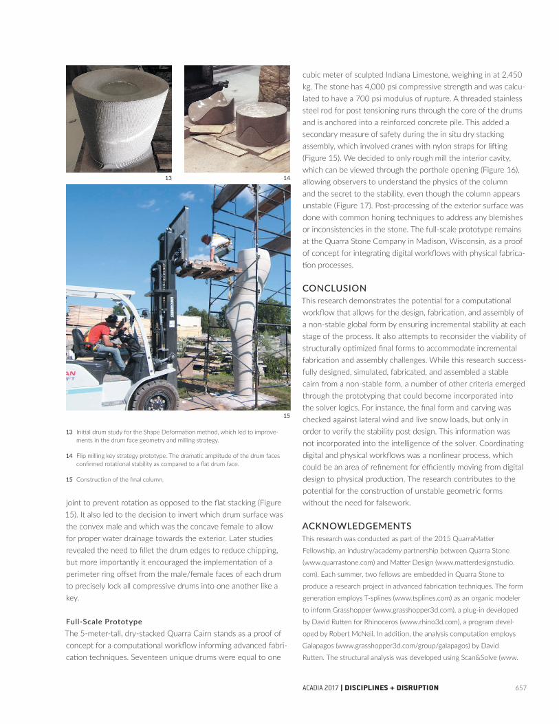
13 Initial drum study for the Shape Deformation method, which led to improve-ments in the drum face geometry and milling strategy.
14 Flip milling key strategy prototype. The dramatic amplitude of the drum faces confirmed rotational stability as compared to a flat drum face.
15 Construction of the final column.
joint to prevent rotation as opposed to the flat stacking (Figure 15). It also led to the decision to invert which drum surface was the convex male and which was the concave female to allow for proper water drainage towards the exterior. Later studies revealed the need to fillet the drum edges to reduce chipping, but more importantly it encouraged the implementation of a perimeter ring offset from the male/female faces of each drum to precisely lock all compressive drums into one another like a key.
Full-Scale PrototypeThe 5-meter-tall, dry-stacked Quarra Cairn stands as a proof of concept for a computational workflow informing advanced fabri-cation techniques. Seventeen unique drums were equal to one
cubic meter of sculpted Indiana Limestone, weighing in at 2,450 kg. The stone has 4,000 psi compressive strength and was calcu-lated to have a 700 psi modulus of rupture. A threaded stainless steel rod for post tensioning runs through the core of the drums and is anchored into a reinforced concrete pile. This added a secondary measure of safety during the in situ dry stacking assembly, which involved cranes with nylon straps for lifting (Figure 15). We decided to only rough mill the interior cavity, which can be viewed through the porthole opening (Figure 16), allowing observers to understand the physics of the column and the secret to the stability, even though the column appears unstable (Figure 17). Post-processing of the exterior surface was done with common honing techniques to address any blemishes or inconsistencies in the stone. The full-scale prototype remains at the Quarra Stone Company in Madison, Wisconsin, as a proof of concept for integrating digital workflows with physical fabrica-tion processes.
CONCLUSIONThis research demonstrates the potential for a computational workflow that allows for the design, fabrication, and assembly of a non-stable global form by ensuring incremental stability at each stage of the process. It also attempts to reconsider the viability of structurally optimized final forms to accommodate incremental fabrication and assembly challenges. While this research success-fully designed, simulated, fabricated, and assembled a stable cairn from a non-stable form, a number of other criteria emerged through the prototyping that could become incorporated into the solver logics. For instance, the final form and carving was checked against lateral wind and live snow loads, but only in order to verify the stability post design. This information was not incorporated into the intelligence of the solver. Coordinating digital and physical workflows was a nonlinear process, which could be an area of refinement for efficiently moving from digital design to physical production. The research contributes to the potential for the construction of unstable geometric forms without the need for falsework.
ACKNOWLEDGEMENTSThis research was conducted as part of the 2015 QuarraMatter
Fellowship, an industry/academy partnership between Quarra Stone
(www.quarrastone.com) and Matter Design (www.matterdesignstudio.
com). Each summer, two fellows are embedded in Quarra Stone to
produce a research project in advanced fabrication techniques. The form
generation employs T-splines (www.tsplines.com) as an organic modeler
to inform Grasshopper (www.grasshopper3d.com), a plug-in developed
by David Rutten for Rhinoceros (www.rhino3d.com), a program devel-
oped by Robert McNeil. In addition, the analysis computation employs
Galapagos (www.grasshopper3d.com/group/galapagos) by David
Rutten. The structural analysis was developed using Scan&Solve (www.

658
16 Visual connection to the interior cavity of the column where mass was removed, looking upwards towards the orifice on the opposite side at the top of the column.
17 Full-scale prototype consisting of 17 unique dry-stacked drums on site.
scan-and-solve.com) by Intact Solutions Inc, and Flow Design (www.
autodesk.com/flow-design) by Autodesk Inc. The fabrication computa-
tion utilizes a custom Grasshopper script by Luisel Zayas to automate
toolpath geometries, SUM3D (cap-us.com) for toolpath generation and
RoboMOVE (www.qdrobotics.com/eng/robomove) by QD Robotics for
robot program simulation. The authors would like to thank Frank Haufe,
Eric Kudrna, and Edgar Galindo for their fabrication support.
REFERENCESAriza, Inés, T. Shan Sutherland, James B. Durham, Caitlin T. Mueller,
Wes McGee, and Brandon Clifford. 2017. “Robotic Fabrication of Stone
Assembly Details.” In Fabricate 2017, edited by Achim Menges, Bob Sheil,
Ruairi Glynn and Marilena Skavara, 106–113. London: UCL Press.
Bächer, Moritz, Emily Whiting, Bernd Bickel, and Olga Sorkine-Hornung.
2014. “Spin-It: Optimizing Moment of Inertia for Spinnable Objects.” In
ACM Transactions on Graphics: Proceedings of ACM SIGGRAPH 2014 33 (4):
96.
Block, Philippe, Tom Van Mele, Matthias Rippmann, Matthew DeJong,
John Ochsendorf, Matt Escobedo, and David Escobedo. 2016. “Armadillo
Vault: An Extreme Discrete Stone Shell.” DETAIL 10: 940–942.
Burry, Mark. 2007. Gaudí Unseen: Completing the Sagrada Familia. Berlin:
Jovis.
———. 2016. “Robots at the Sagrada Familia Basilica: A Brief History of
Robotised Stone-Cutting.” In Robotic Fabrication in Architecture, Art and
Design, edited by Dagmar Reinhardt, Rob Saunders, and Jane Burry, 2–15.
Cham, Switzerland: Springer.
Clifford, Brandon. 2016. “The McKnelly Megalith: A Method of Organic
Modeling Feedback.” In ACADIA // 2016: Posthuman Frontiers: Data,
Designers, and Cognitive Machines, Proceedings of the 36th Annual
Conference of the Association for Computer Aided Design in Architecture,
edited by Kathy Velikov, Sean Ahlquist, Matias del Campo, and Geoffrey
Thün, 440–9. Ann Arbor: ACADIA.
Fallacara, Giuseppe. 2007. “Digital Stereotomy and Topological
Transformations: Reasoning about Shape Building.” In Proceedings of
the Second International Congress on Construction History, 1075–92.
Cambridge, UK: CHS.
Huerta, Santiago. 2013. “El cálculo de estructuras en la obra de Gaudí.”
En Ingeniería Civil 130: 121–133.
Kilian, Axel. and John Ochsendorf. 2005. “Particle-Spring Systems for
Structural Form Finding.” Journal of the International Association for Shell
and Spatial Structures 46: 147.
Prévost, Romain, Emily Whiting, Sylvain Lefebvre, and Olga Sorkine-
Hornung. 2013. “Make It Stand: Balancing Shapes for 3D Fabrication.”
ACM Transactions on Graphics: SIGGRAPH 2013 Conference Proceedings 32
(4): 81.
Rasch, Bodo, and Frei Otto. 1996. Finding Form: Towards an Architecture of
the Minimal. Stuttgart, Germany: Edition Axel Menges.
Rippmann, Matthias, John Curry, David Escobedo, and Philippe Block.
2013. “Optimising Stone-Cutting Strategies for Freeform Masonry Vaults.”
In Proceedings of the International Association for Shell and Spatial Structures
Symposium. Wroclaw, Poland: IASS.
IMAGE CREDITSAll drawings and images by the authors.
Quarra Cairn Zayas, Brugmann, Clifford, McGee, Durham
16

659ACADIA 2017 | DISCIPLINES + DISRUPTION
Luisel Zayas San Miguel did his schooling in San Juan, where he
received an Environmental Design degree from the University of Puerto
Rico in 2012, and a Master of Architecture from Massachusetts Institute
of Technology in 2016, where he received The Bill Mitchell Fund ++
Award and the Arthur Rotch Prize. He currently works at NADAAA,
where he serves as an architectural designer and maker at the NadLab.
Luisel was appointed the QuarraMatter Research Fellowship in 2015 and
in 2016 he collaborated with the Block Research Group (ETH), ODB,
and Norman Foster Foundation for the Droneport pavilion at the Venice
Biennale.
Dustin Brugmann is a FABLab Research Associate and Lecturer at the
University of Michigan. He received his Master of Architecture from the
University of Michigan in 2015 and Bachelor of Arts in Architecture from
Miami University of Ohio in 2010. He worked for the Danish Institute
for Study Abroad from 2010–11, Bernard Tschumi Architects as a Junior
Designer from 2011–13, and was also awarded the Quarra Stone /
Matter Design Research Fellowship in 2015. His research interests span
digital and craft methods of making towards hybrid and novel methods of
architectural production.
Brandon Clifford is an Assistant Professor at the Massachusetts
Institute of Technology and Principal at Matter Design. Brandon received
his Master of Architecture from Princeton University in 2011 and
Bachelor of Science in Architecture from Georgia Tech in 2006. He
worked as project manager at Office dA from 2006–09, LeFevre Fellow
at OSU from 2011–12, and Belluschi Lecturer at MIT from 2012–16.
Brandon has been awarded the Design Biennial Boston Award, the
Architectural League Prize, the SOM Prize, and the Founders Rome Prize.
Brandon's translation of past knowledge into contemporary practice
continues to provoke new directions for digital design.
Wes McGee is an Assistant Professor in Architecture and the Director
of the FABLab at the University of Michigan Taubman College of
Architecture and Urban Planning. His work revolves around the interro-
gation of the means and methods of material production in the digital
era, through research focused on developing new connections between
design, engineering, materials, and manufacturing processes as they
relate to the built environment.
James Durham is founder (1989) and owner of Quarra Stone Company,
LLC. James is a graduate of Earlham College and majored in Chemistry.
For over 40 years, James has operated stone quarries, fabricated and sold
cut and carved limestone, marble, granite, sandstone and quartzite (the
famous Vals quartzite used in Zumthor’s Therme Spa in Vals, Switzerland).
His companies have carved stone for the US Capitol (Visitor’s Center
2003–2008), US Supreme Court (2006–2008) as well as 6 state capitol
restorations. In 2012, James received an honorary degree as Master
Carver from the German State School for Stoneworking in Wunsiedel,
Germany. James’s company is a leading producer in digital manufacturing
of natural stone.
17