
LUCID User’s Guide
212
LUCID LUCID User’s Guide LUCID Copyright © 1990-1995 by The Saskatchewan Accelerator Laboratory Permission to use, copy, modify, and distribute this software and its documentation for any purpose and without fee is hereby granted, provided that the above copyright no- tice appear in all copies and that both that copyright notice and this permission notice appear in supporting documentation, and that the name of Doug Murray and the Saskatchewan Accelerator Laboratory not be used in advertising or publicity pertain- ing to distribution of the software without specific, written prior permission. Neither Doug Murray nor the Saskatchewan Accelerator Laboratory make any representations about the suitability of this software for any purpose. It is provided “as is” without ex- press or implied warranty. The sale of any product based wholly or in part upon the technology provided by LU- CID is strictly forbidden without specific, prior written permission from the Saskatchewan Accelerator Laboratory. LUCID technology includes, but is not limited to, the source code, executable binary files, specification language, and sample specifi- cation (description) files. Comments, bug reports and changes to this software or documentation should be mailed to [email protected]. Bug reports should be accompanied by sample in- put or description files if appropriate. UNIX and OPEN LOOK are registered trademarks of Novell, Inc. Sun Microsystems and Sun Workstation are registered trademarks of Sun Microsys- tems, Inc. XView, SunView, and OpenWindows are trademarks of Sun Microsystems, Inc. DIGITAL, MicroVAX, and ULTRIX are trademarks of Digital Equipment Corpora- tion. X Window System is a trademark and product of Massachusetts Institute of Technol- ogy.
Transcript of LUCID User’s Guide
LUCID
LUCID User’s Guide
LUCID Copyright © 1990-1995 byThe Saskatchewan Accelerator Laboratory
Permission to use, copy, modify, and distribute this software and its documentation forany purpose and without fee is hereby granted, provided that the above copyright no-tice appear in all copies and that both that copyright notice and this permission noticeappear in supporting documentation, and that the name of Doug Murray and theSaskatchewan Accelerator Laboratory not be used in advertising or publicity pertain-ing to distribution of the software without specific, written prior permission. NeitherDoug Murray nor the Saskatchewan Accelerator Laboratory make any representationsabout the suitability of this software for any purpose. It is provided “as is” without ex-press or implied warranty.
The sale of any product based wholly or in part upon the technology provided by LU-CID is strictly forbidden without specific, prior written permission from theSaskatchewan Accelerator Laboratory. LUCID technology includes, but is not limitedto, the source code, executable binary files, specification language, and sample specifi-cation (description) files.
Comments, bug reports and changes to this software or documentation should bemailed to [email protected]. Bug reports should be accompanied by sample in-put or description files if appropriate.
UNIX and OPEN LOOK are registered trademarks of Novell, Inc.
Sun Microsystems and Sun Workstation are registered trademarks of Sun Microsys-tems, Inc.
XView, SunView, and OpenWindows are trademarks of Sun Microsystems, Inc.
DIGITAL, MicroVAX, and ULTRIX are trademarks of Digital Equipment Corpora-tion.
X Window System is a trademark and product of Massachusetts Institute of Technol-ogy.

LUCID

LUCID
Contents
Lucid User’s Guide - i
Chapter 1 A Tutorial IntroductionA Short Tutorial Session.................................................................... 1-2
Starting an Experiment.....................................................................1-4Using the Help Facility.....................................................................1-6Building the Experiment ..................................................................1-7Controlling the Analysis ................................................................1-11Sending Pre-defined Commands..................................................1-16How to Quit Lucid ..........................................................................1-16
Where to Go from Here................................................................... 1-17
Chapter 2 Using LUCIDGetting Started.................................................................................... 2-1
The LUCID Program ......................................................................... 2-3
Menu Buttons.....................................................................................2-5The Experiments Menu .................................................................. 2-6The Build Menu ............................................................................... 2-8The Control Menu ......................................................................... 2-12The View Menu.............................................................................. 2-14The Properties Menu..................................................................... 2-15The Quit Button ............................................................................. 2-18
Control Buttons ...............................................................................2-19The Record Button......................................................................... 2-20The Play Button ............................................................................. 2-20The Playback Sequence Button.................................................... 2-20The Pause Button........................................................................... 2-21The Stop Button ............................................................................. 2-21The Rewind Button ....................................................................... 2-21The Forward Button...................................................................... 2-22The Eject Button............................................................................. 2-22The Update Visible Button........................................................... 2-22
Status Buttons ..................................................................................2-22
The Histogram Windows................................................................ 2-23
The File Menu Button .....................................................................2-24Shortcuts for the File Menu.......................................................... 2-26
LUCID
Contents
Lucid User’s Guide - ii
The View Menu Button ..................................................................2-27Shortcuts for the View Menu....................................................... 2-32Marker Mode.................................................................................. 2-34Region Mode .................................................................................. 2-37Scale Mode...................................................................................... 2-39Zoom Mode .................................................................................... 2-41Pan Mode........................................................................................ 2-42Temporary Scale, Zoom and Pan Modes ................................... 2-43Window Mode ............................................................................... 2-44Title Mode....................................................................................... 2-44
The Edit Menu Button ....................................................................2-44The Edit Data Option .................................................................... 2-44The Density Map Option.............................................................. 2-44The Get Region Option ................................................................. 2-44The Send Region Option .............................................................. 2-45The Save Region Option ............................................................... 2-45
The Print Menu Button...................................................................2-46The Print Option............................................................................ 2-46The Layout Option ........................................................................ 2-46
Chapter 3 The ReaderCamac Hardware Layout.................................................................. 3-1
Using Lams ........................................................................................3-2
Making a Reader Description File ................................................... 3-2
Four Sections of a Description File .................................................3-3The DEFINE Section .........................................................................3-4
How to DEFINE Variables ............................................................. 3-6The TRIGGER Section ......................................................................3-8The USER CODE Section ...............................................................3-11The EVENT Section.........................................................................3-12
Using Variables.............................................................................. 3-12Reading Data.................................................................................. 3-14Saving Data .................................................................................... 3-18Other CAMAC Operations .......................................................... 3-19Polling Camac Modules................................................................ 3-20CAMAC Q Response .................................................................... 3-21Compressing Array Data ............................................................. 3-21Calculations and Variables........................................................... 3-23Printing Messages During Event Processing ............................ 3-24Making Decisions about the Data ............................................... 3-25Triggering Another Event ............................................................ 3-26Rejecting an Event ......................................................................... 3-26

LUCID
Contents
Lucid User’s Guide - iii
Writing to Camac Modules .......................................................... 3-26Loading Data into a CAMAC Module ....................................... 3-27Specialized Camac Access............................................................ 3-28Camac Crate Operations .............................................................. 3-28User-written Code ......................................................................... 3-29Stopping or Suspending an Experiment .................................... 3-30Words Reserved for the Reader Description............................. 3-31
Chapter 4 The LookerHow the LOOKER Works................................................................. 4-1
Making a LOOKER Description File ............................................... 4-2
The DEFINE Section .........................................................................4-3Types of Variables ........................................................................... 4-3Defining Histograms....................................................................... 4-4Defining Regions ............................................................................. 4-5Defining Functions .......................................................................... 4-6Arrays of Variables.......................................................................... 4-6Groups of Variables ........................................................................ 4-7
The EVENT Section...........................................................................4-8Event Types ...................................................................................... 4-8Using Variables.............................................................................. 4-12Calculations and Assignment of Values .................................... 4-13Incrementing Histograms............................................................. 4-16Assigning Histograms To and From Arrays ............................. 4-18Using Regions With Histograms................................................. 4-18Incrementing Two Dimensional Histograms............................ 4-20Using Two Dimensional Regions................................................ 4-20The If-then-else Statement............................................................ 4-21The Repeat Statement ................................................................... 4-23Printing Values from the LOOKER ............................................ 4-24Loading Histograms from Files or Programs............................ 4-24Setting Looker Variables Interactively ....................................... 4-25Using Your Own Subroutines ..................................................... 4-25
LOOKER Histograms ...................................................................... 4-26
Histogram Definition......................................................................4-27Defining Histograms..................................................................... 4-28
Histogram Regions .........................................................................4-33Defining Two-Dimensional Histograms .....................................4-36Defining Two-Dimensional Regions ............................................4-39Histogramming Bit Positions ........................................................4-40

LUCID
Contents
Lucid User’s Guide - iv
LOOKER Keywords ........................................................................ 4-41
Chapter 5 The WriterSaving Event Data.............................................................................5-2Critical Data Destinations ................................................................5-2Efficiency ............................................................................................5-3Examples ............................................................................................5-3
Chapter 6 Conceptual OverviewHow LUCID Works ........................................................................... 6-1
A Conceptual View of LUCID.........................................................6-2Data Communications in LUCID ...................................................6-3The LUCID Experiment Directory..................................................6-4
Programming Languages Used ....................................................... 6-6
Chapter 7 Utility Programs and SubroutinesUtility Programs................................................................................. 7-1
addclient (system) ........................................................................... 7-1copyrun ............................................................................................. 7-1demolucid......................................................................................... 7-2extractrun.......................................................................................... 7-2findeot ............................................................................................... 7-2generate............................................................................................. 7-2hv1440 ............................................................................................... 7-3hv4032 ............................................................................................... 7-3intape................................................................................................. 7-3lucid ................................................................................................... 7-3lucid_to_q ......................................................................................... 7-3lucidlog ............................................................................................. 7-3lucidman ........................................................................................... 7-4lucidview .......................................................................................... 7-4netcamac ........................................................................................... 7-5netcrateinit ........................................................................................ 7-5nethv.................................................................................................. 7-5qview ................................................................................................. 7-7readsara............................................................................................. 7-7vme_console ..................................................................................... 7-7
LUCID
Contents
Lucid User’s Guide - v
The lucid Command.......................................................................... 7-8
LUCID Functions and Subroutines ............................................... 7-10
Accessing Networked Directories ................................................7-10Reading LUCID Data Files ............................................................7-10Writing LUCID Data Records .......................................................7-11Generating LUCID Data Files .......................................................7-11Low Level CAMAC Access ...........................................................7-12High Voltage Access .......................................................................7-13Reading Q-format Data ..................................................................7-14Writing Q-format Data ...................................................................7-14
LUCID Data File Format ................................................................ 7-15
LUCID Data Record Format Declarations...................................7-15
Appendix A The CAMAC Module DatabaseDefining the Modules....................................................................... A-1
CAMAC Capabilities .......................................................................A-2Readsize and Writesize.................................................................. A-2Shortword and Longword ............................................................ A-3Checking Module Identity ............................................................ A-3Read.................................................................................................. A-4HOLD Mode Transfers .................................................................. A-4Write ................................................................................................. A-5Read and Clear................................................................................ A-5Clear ................................................................................................. A-5Enabling and Disabling LAMs ..................................................... A-5Testing for LAM Status.................................................................. A-6Clearing LAMs................................................................................ A-6Self-Clearing Modules ................................................................... A-6Q-Stop Modules.............................................................................. A-7Self-compressing Modules ............................................................ A-7
Sample CAMAC Module Database................................................ A-8
Appendix B Example Description FilesAppendix C Known Problems
Known Bugs....................................................................................... C-1
Problems When Running Off-Line. ............................................. C-1Problems When Running On-Line............................................... C-2
Requested Enhancements ................................................................ C-2
Changes to READER ....................................................................... C-2Changes to WRITER ........................................................................ C-2Changes to LOOKER ....................................................................... C-2Changes to XLUCID ........................................................................ C-3

LUCID
Contents
Lucid User’s Guide - vi
Appendix D Histogram Save File FormatOverview............................................................................................ D-1
Header ...............................................................................................D-1Body ...................................................................................................D-2
LUCID
1-1
Chapter
1 A Tutorial Introduction
LUCID is a system which provides a way to acquire and analyzeexperimental data. It sets up a data stream that has three distinctparts: the READER, the LOOKER and the WRITER.
1. The READER gets data from some source such as CAMAC. Itcan perform simple software cuts, then make the dataavailable to the rest of the system.
2. The LOOKER is optional, and allows analysis of the data as itis being acquired. Although its name implies passively view-ing the data, the LOOKER can perform elaborate tests andmathematical operations on the data.
3. The WRITER is also optional, and can save data on magnetictape, in disk files, or send the data to other programs as in-put.
LUCID’s knowledge of an experiment comes from the user’s de-scription of it; the user is required to make up description filesfor each of the READER and LOOKER. The experimenter startsand controls his experiment with the XLUCID command, whichallows interaction with the READER, LOOKER, and WRITER,and lets the user change important parameters dynamically.
lu•cid (loo´cid) 1. bright; shining. 2. transparent. 3. designatingan interval of sanity in a mental disorder. 4. clear to the mind;readily understood [lucid instructions] 5. clearheaded; rational[a lucid thinker] - lu•cid´i•ty, lu´cid•ness n. lu´cid•ly adv.
A Tutorial Introduction
A Short Tutorial Session 1-2
LUCID
A Short Tutorial Session
The best way to learn how to use LUCID is to sit down and try it!You need a few things to get started. First, make sure that youhave an account on the computer system. You’ll be given a log-in name and a password which will let you access most comput-ers in the Laboratory network. Second, find an available work-station and type in your login name and password.
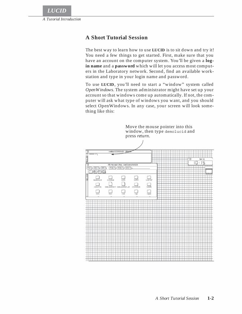
To use LUCID, you’ll need to start a “window” system calledOpenWindows. The system administrator might have set up youraccount so that windows come up automatically. If not, the com-puter will ask what type of windows you want, and you shouldselect OpenWindows. In any case, your screen will look some-thing like this:
Move the mouse pointer into thiswindow, then type demolucid andpress return.
A Tutorial Introduction
A Short Tutorial Session 1-3
LUCID
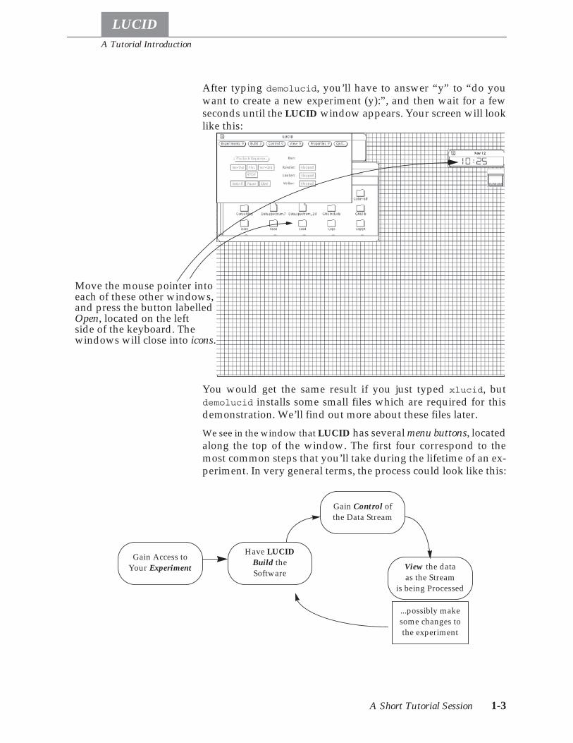
After typing demolucid, you’ll have to answer “y” to “do youwant to create a new experiment (y):”, and then wait for a fewseconds until the LUCID window appears. Your screen will looklike this:
You would get the same result if you just typed xlucid, butdemolucid installs some small files which are required for thisdemonstration. We’ll find out more about these files later.
We see in the window that LUCID has several menu buttons, locatedalong the top of the window. The first four correspond to themost common steps that you’ll take during the lifetime of an ex-periment. In very general terms, the process could look like this:
Move the mouse pointer intoeach of these other windows,and press the button labelledOpen, located on the leftside of the keyboard. Thewindows will close into icons.
Gain Access toYour Experiment
Have LUCIDBuild theSoftware
Gain Control ofthe Data Stream
View the dataas the Stream
is being Processed
...possibly makesome changes tothe experiment
A Tutorial Introduction
A Short Tutorial Session 1-4
LUCID
Buttons are drawn on the screen to allow choices to be made. Tomake a selection, move the mouse arrow over top of the button,and click it; that is, press then release the leftmost button on themouse; the left mouse button is called the select button.
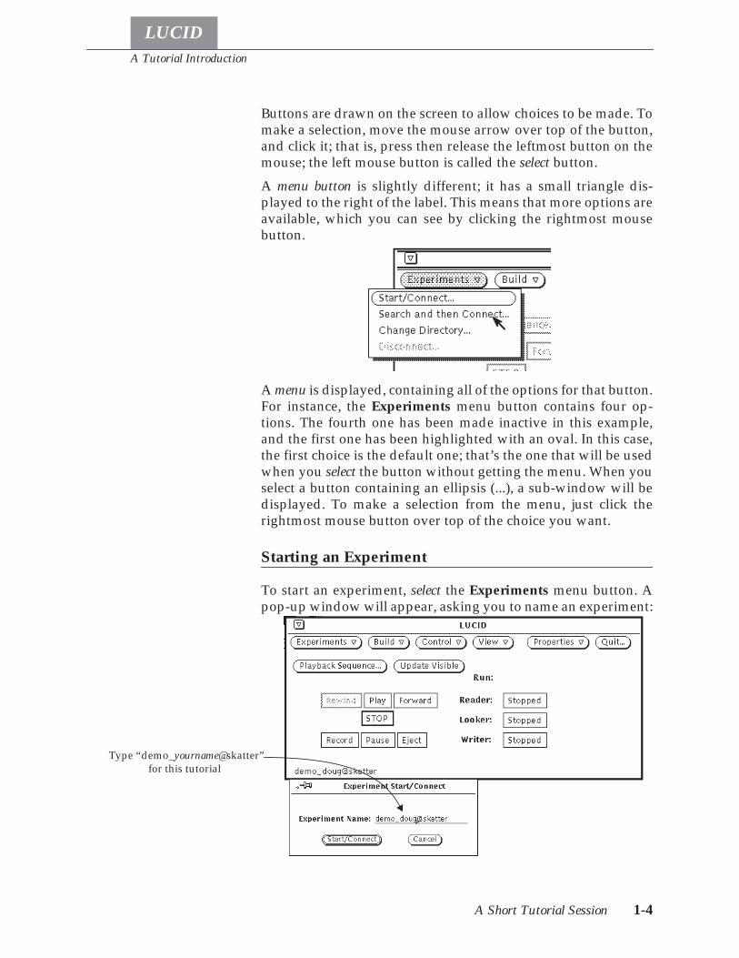
A menu button is slightly different; it has a small triangle dis-played to the right of the label. This means that more options areavailable, which you can see by clicking the rightmost mousebutton.
A menu is displayed, containing all of the options for that button.For instance, the Experiments menu button contains four op-tions. The fourth one has been made inactive in this example,and the first one has been highlighted with an oval. In this case,the first choice is the default one; that’s the one that will be usedwhen you select the button without getting the menu. When youselect a button containing an ellipsis (...), a sub-window will bedisplayed. To make a selection from the menu, just click therightmost mouse button over top of the choice you want.
Starting an Experiment
To start an experiment, select the Experiments menu button. Apop-up window will appear, asking you to name an experiment:
Type “demo_yourname@skatter”for this tutorial

A Tutorial Introduction
A Short Tutorial Session 1-5
LUCID
You’re going to create a new “experiment” using your ownname as a base. Make sure that the pointer is pointing into theExperiment Start/Connect sub-window, then (using your loginname instead of name), type demo_name@skatter and press re-turn1. First, you’ll be asked to confirm your choice, then to con-firm that the experiment should be created:
Use your own name, but make sure that it starts with the word“demo_...”, so it won’t be mistaken for a permanent experiment.
Select the Create button if LUCID is displaying the correct name.You won’t be able to do anything else until you’ve assured LU-CID that you’ve seen it’s message. You can also just press returnto confirm your request.
After a moment, the Experiment Start/Connect sub-window willdisappear and a label at the bottom left of the LUCID windowwill name the current experiment.
1. You can press return, or select the Start/Connect button after typing the name. It is usually true thatpressing return on the keyboard is the same as selecting the “confirmation” button (the button withthe double border).
The experiment name appearsat the bottom of the window whenyou’re successfully connected.
A Tutorial Introduction
A Short Tutorial Session 1-6
LUCID
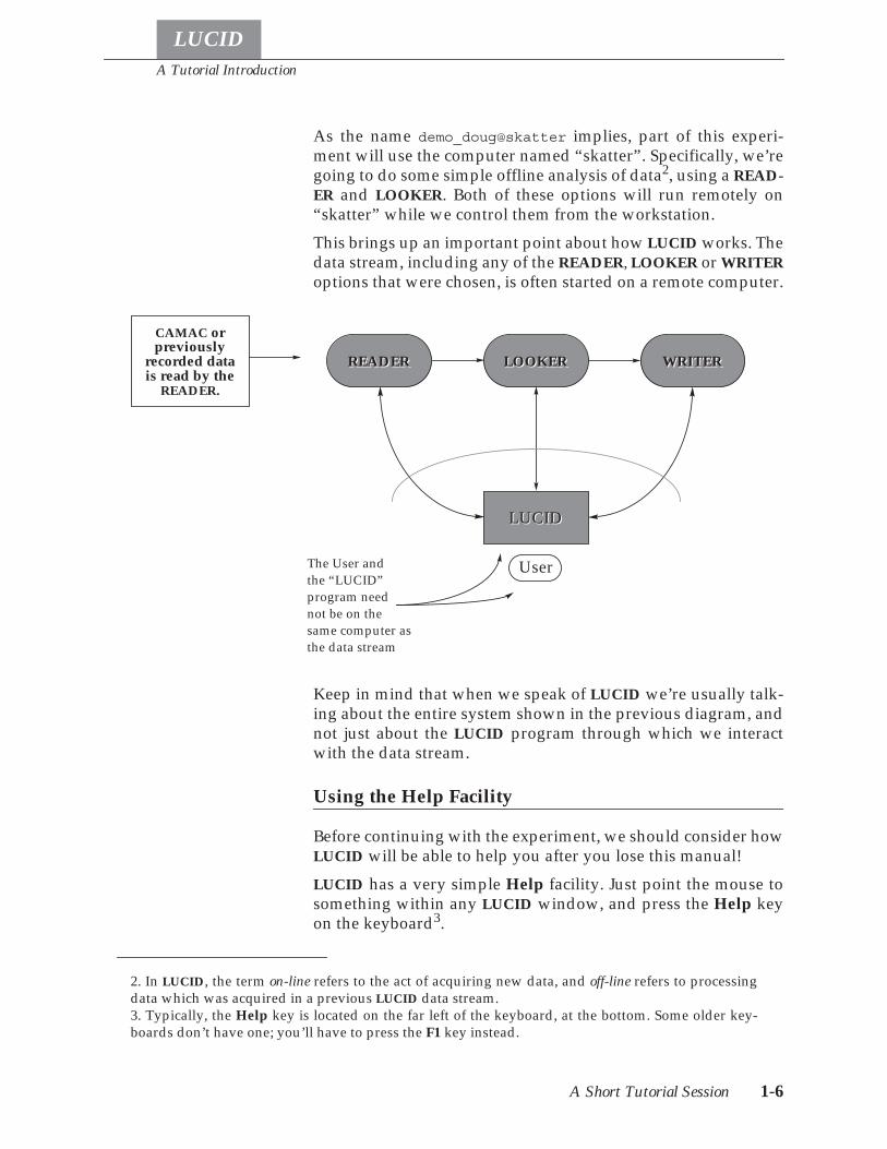
As the name demo_doug@skatter implies, part of this experi-ment will use the computer named “skatter”. Specifically, we’regoing to do some simple offline analysis of data2, using a READ-ER and LOOKER. Both of these options will run remotely on“skatter” while we control them from the workstation.
This brings up an important point about how LUCID works. Thedata stream, including any of the READER, LOOKER or WRITERoptions that were chosen, is often started on a remote computer.
Keep in mind that when we speak of LUCID we’re usually talk-ing about the entire system shown in the previous diagram, andnot just about the LUCID program through which we interactwith the data stream.
Using the Help Facility
Before continuing with the experiment, we should consider howLUCID will be able to help you after you lose this manual!
LUCID has a very simple Help facility. Just point the mouse tosomething within any LUCID window, and press the Help keyon the keyboard3.
2. In LUCID, the term on-line refers to the act of acquiring new data, and off-line refers to processingdata which was acquired in a previous LUCID data stream.3. Typically, the Help key is located on the far left of the keyboard, at the bottom. Some older key-boards don’t have one; you’ll have to press the F1 key instead.
LUCID
WRITERWRITERLOOKERLOOKERREADERREADER
CAMAC orpreviously
recorded data
LUCID
UserThe User andthe “LUCID”program neednot be on thesame computer asthe data stream
READER.is read by the
A Tutorial Introduction
A Short Tutorial Session 1-7
LUCID
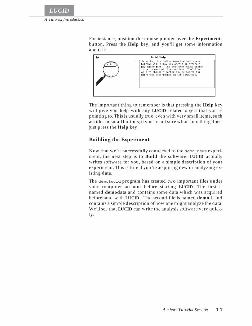
For instance, position the mouse pointer over the Experimentsbutton. Press the Help key, and you’ll get some informationabout it:
The important thing to remember is that pressing the Help keywill give you help with any LUCID related object that you’repointing to. This is usually true, even with very small items, suchas titles or small buttons; if you’re not sure what something does,just press the Help key!
Building the Experiment
Now that we’re successfully connected to the demo_name experi-ment, the next step is to Build the software. LUCID actuallywrites software for you, based on a simple description of yourexperiment. This is true if you’re acquiring new or analyzing ex-isting data.
The demolucid program has created two important files underyour computer account before starting LUCID. The first isnamed demodata and contains some data which was acquiredbeforehand with LUCID. The second file is named demo.l, andcontains a simple description of how one might analyze the data.We’ll see that LUCID can write the analysis software very quick-ly.
A Tutorial Introduction
A Short Tutorial Session 1-8
LUCID
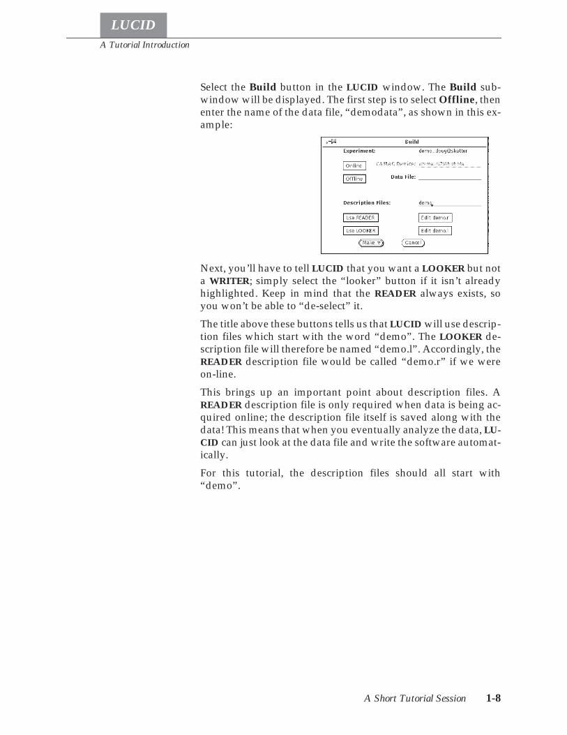
Select the Build button in the LUCID window. The Build sub-window will be displayed. The first step is to select Offline, thenenter the name of the data file, “demodata”, as shown in this ex-ample:
Next, you’ll have to tell LUCID that you want a LOOKER but nota WRITER; simply select the “looker” button if it isn’t alreadyhighlighted. Keep in mind that the READER always exists, soyou won’t be able to “de-select” it.
The title above these buttons tells us that LUCID will use descrip-tion files which start with the word “demo”. The LOOKER de-scription file will therefore be named “demo.l”. Accordingly, theREADER description file would be called “demo.r” if we wereon-line.
This brings up an important point about description files. AREADER description file is only required when data is being ac-quired online; the description file itself is saved along with thedata! This means that when you eventually analyze the data, LU-CID can just look at the data file and write the software automat-ically.
For this tutorial, the description files should all start with“demo”.

A Tutorial Introduction
A Short Tutorial Session 1-9
LUCID
Now lets see what a description file looks like. At the right sideof the window are the edit buttons, which allow you to create orchange a description file. Choose the box labelled “Edit demo.l”,and a sub-window will appear containing a simple LOOKER de-scription file:
The window that appears is actually a text editor. By positioningthe pointer and selecting a position in the file, you’ll be able toeasily change the contents. Chapter Four will discuss in detailwhat the description file can contain, but for now lets just lookbriefly at this small example.
• The first line tells LUCID that when the data was first ac-quired, an array of twelve integers was saved. This state-ment isn’t required because LUCID can find the array inthe data file. It’s a good idea to include it, since it allowsLUCID to check that it’s got the right data file. In our case,this array represents the twelve inputs on a peak-sensingADC.
• This tells LUCID that the LOOKER will need an array oftwelve histograms, each one accepting values from 0 to2048. By default, histograms contain 1024 bins.
• This line instructs the LOOKER to perform the next twolines whenever an event named “demo_event” is en-countered in the data stream.
• The appropriate bin in each of the twelve histograms is in-cremented by using the values from each of the corre-sponding twelve ADC elements.
• Next, LUCID is told to perform some instructions when-ever the experimenter gives a “reset” command;
• Specifically, all bins of every histogram within the spec-trum array will be set to zero.
define demo_adc[12] previous data int*2
define spectrum[12] histogram from 0 to 2048
event demo_event:
increment spectrum using demo_adc
command "reset":
spectrum = 0
A Tutorial Introduction
A Short Tutorial Session 1-10
LUCID
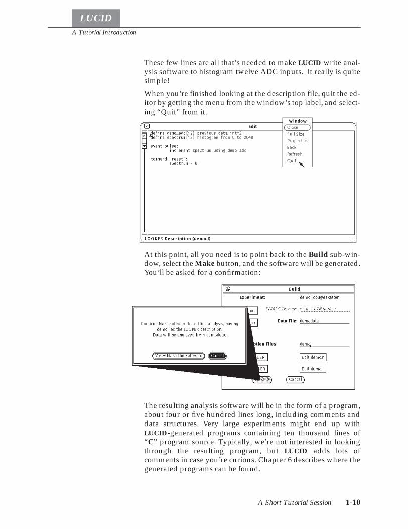
These few lines are all that’s needed to make LUCID write anal-ysis software to histogram twelve ADC inputs. It really is quitesimple!
When you’re finished looking at the description file, quit the ed-itor by getting the menu from the window’s top label, and select-ing “Quit” from it.
At this point, all you need is to point back to the Build sub-win-dow, select the Make button, and the software will be generated.You’ll be asked for a confirmation:
The resulting analysis software will be in the form of a program,about four or five hundred lines long, including comments anddata structures. Very large experiments might end up withLUCID-generated programs containing ten thousand lines of“C” program source. Typically, we’re not interested in lookingthrough the resulting program, but LUCID adds lots ofcomments in case you’re curious. Chapter 6 describes where thegenerated programs can be found.
A Tutorial Introduction
A Short Tutorial Session 1-11
LUCID
While LUCID is making your software and compiling it, a stop-watch figure will be displayed instead of the regular mousepointer. When the pointer reappears, LUCID will have finishedmaking the software. Most of the buttons in the main LUCIDwindow will now be made usable, and the word “Offline” willappear in the lower right corner.
Controlling the Analysis
The main buttons in the LUCID window are meant to resemblecontrols of a simple tape deck or home CD player; you’re al-lowed to rewind or replay the “tape”, which can actually be areal data tape, but also a disk file or any other item containingyour data. Actually, all of the windows we’ve seen here are usedfor online analysis and data acquisition, too.
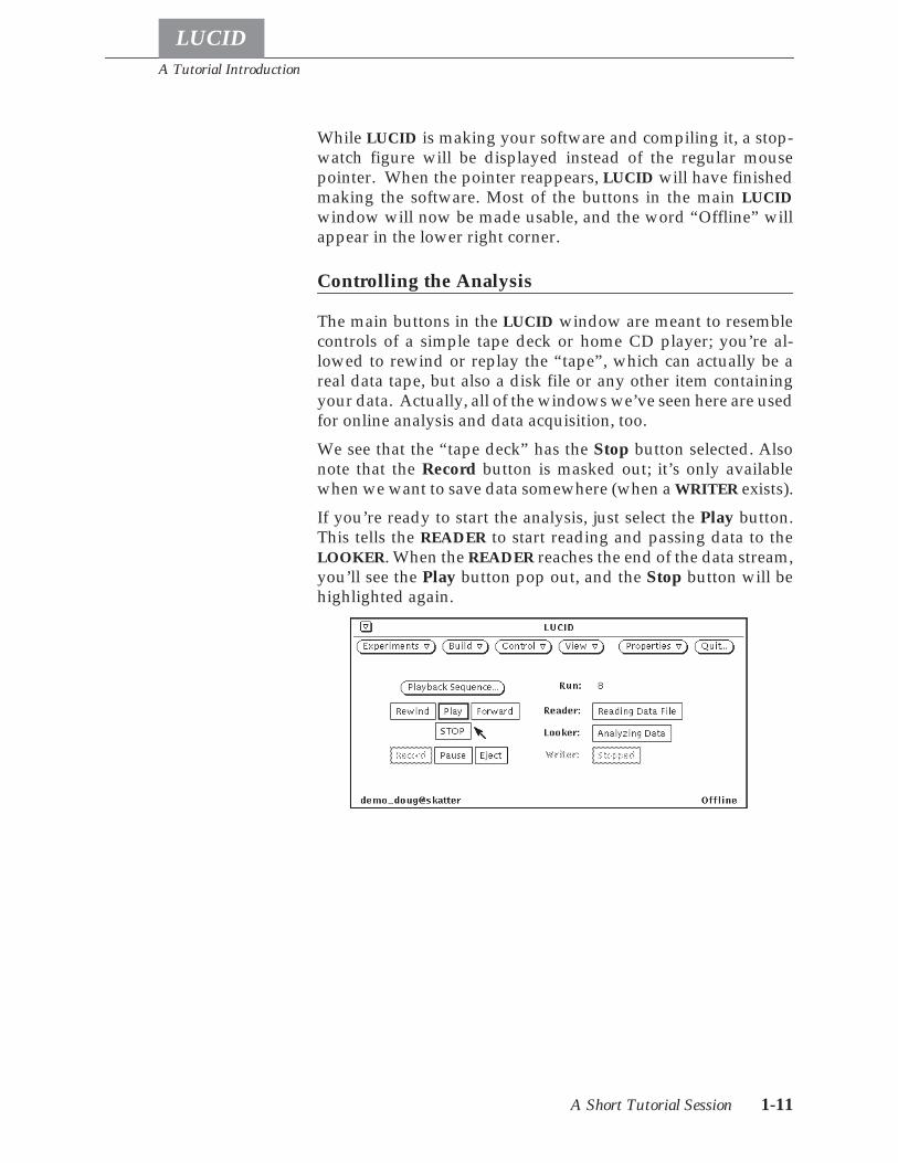
We see that the “tape deck” has the Stop button selected. Alsonote that the Record button is masked out; it’s only availablewhen we want to save data somewhere (when a WRITER exists).
If you’re ready to start the analysis, just select the Play button.This tells the READER to start reading and passing data to theLOOKER. When the READER reaches the end of the data stream,you’ll see the Play button pop out, and the Stop button will behighlighted again.
A Tutorial Introduction
A Short Tutorial Session 1-12
LUCID
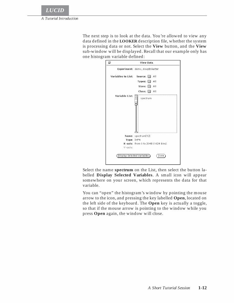
The next step is to look at the data. You’re allowed to view anydata defined in the LOOKER description file, whether the systemis processing data or not. Select the View button, and the Viewsub-window will be displayed. Recall that our example only hasone histogram variable defined:
Select the name spectrum on the List, then select the button la-belled Display Selected Variables. A small icon will appearsomewhere on your screen, which represents the data for thatvariable.
You can “open” the histogram’s window by pointing the mousearrow to the icon, and pressing the key labelled Open, located onthe left side of the keyboard. The Open key is actually a toggle,so that if the mouse arrow is pointing to the window while youpress Open again, the window will close.
A Tutorial Introduction
A Short Tutorial Session 1-13
LUCID
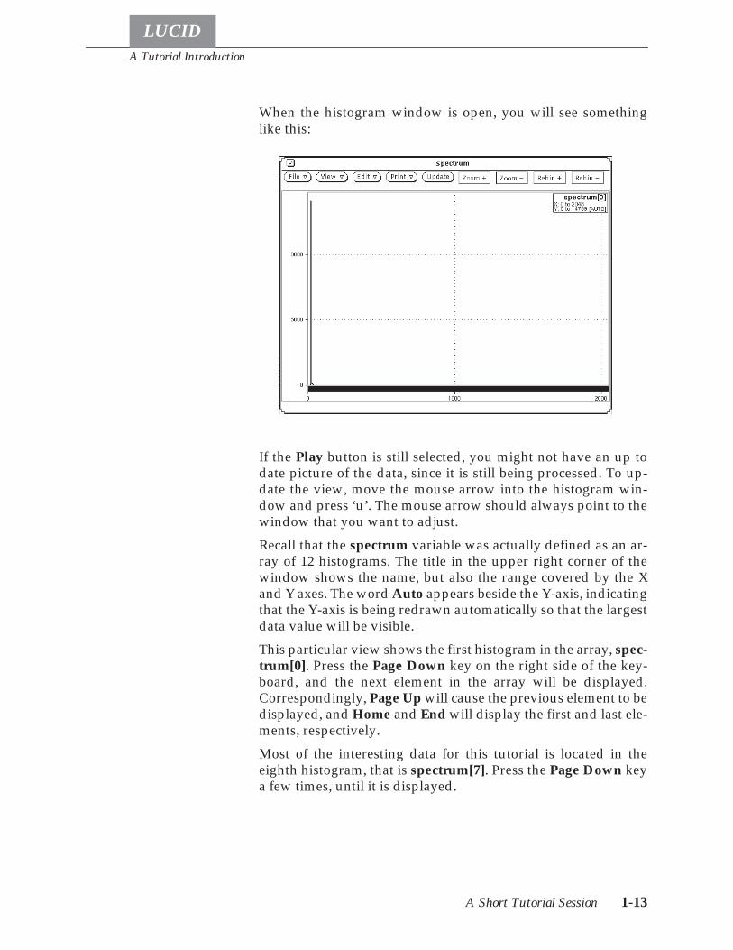
When the histogram window is open, you will see somethinglike this:
If the Play button is still selected, you might not have an up todate picture of the data, since it is still being processed. To up-date the view, move the mouse arrow into the histogram win-dow and press ‘u’. The mouse arrow should always point to thewindow that you want to adjust.
Recall that the spectrum variable was actually defined as an ar-ray of 12 histograms. The title in the upper right corner of thewindow shows the name, but also the range covered by the Xand Y axes. The word Auto appears beside the Y-axis, indicatingthat the Y-axis is being redrawn automatically so that the largestdata value will be visible.
This particular view shows the first histogram in the array, spec-trum[0]. Press the Page Down key on the right side of the key-board, and the next element in the array will be displayed.Correspondingly, Page Up will cause the previous element to bedisplayed, and Home and End will display the first and last ele-ments, respectively.
Most of the interesting data for this tutorial is located in theeighth histogram, that is spectrum[7]. Press the Page Down keya few times, until it is displayed.
A Tutorial Introduction
A Short Tutorial Session 1-14
LUCID
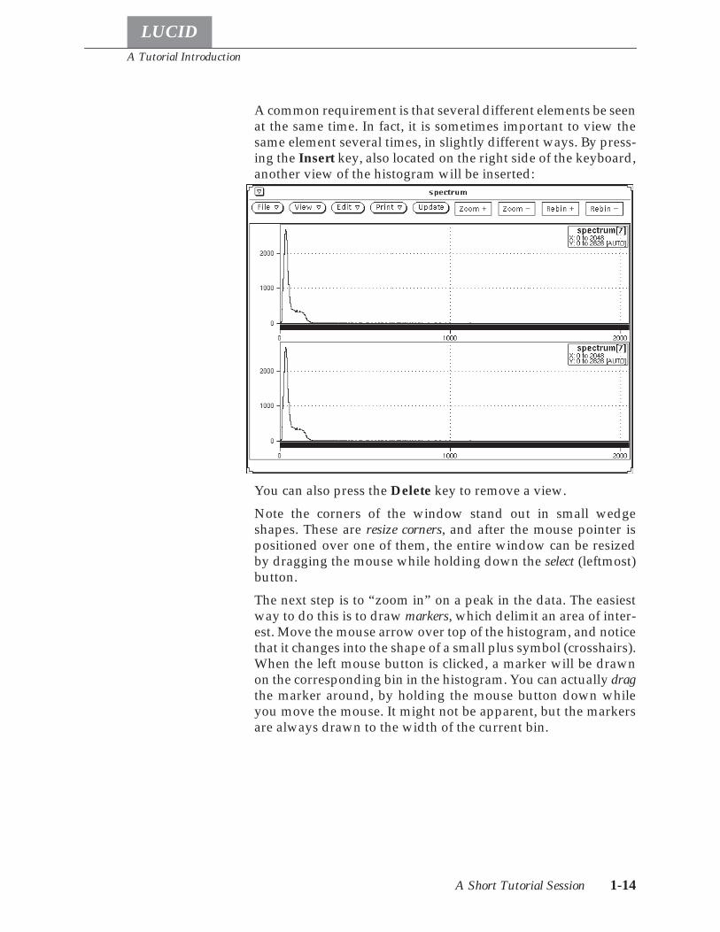
A common requirement is that several different elements be seenat the same time. In fact, it is sometimes important to view thesame element several times, in slightly different ways. By press-ing the Insert key, also located on the right side of the keyboard,another view of the histogram will be inserted:
You can also press the Delete key to remove a view.
Note the corners of the window stand out in small wedgeshapes. These are resize corners, and after the mouse pointer ispositioned over one of them, the entire window can be resizedby dragging the mouse while holding down the select (leftmost)button.
The next step is to “zoom in” on a peak in the data. The easiestway to do this is to draw markers, which delimit an area of inter-est. Move the mouse arrow over top of the histogram, and noticethat it changes into the shape of a small plus symbol (crosshairs).When the left mouse button is clicked, a marker will be drawnon the corresponding bin in the histogram. You can actually dragthe marker around, by holding the mouse button down whileyou move the mouse. It might not be apparent, but the markersare always drawn to the width of the current bin.
A Tutorial Introduction
A Short Tutorial Session 1-15
LUCID
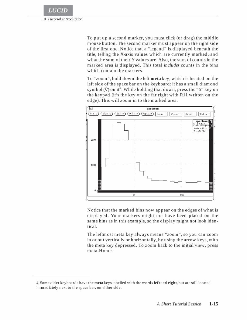
To put up a second marker, you must click (or drag) the middlemouse button. The second marker must appear on the right sideof the first one. Notice that a “legend” is displayed beneath thetitle, telling the X-axis values which are currently marked, andwhat the sum of their Y values are. Also, the sum of counts in themarked area is displayed. This total includes counts in the binswhich contain the markers.
To “zoom”, hold down the left meta key, which is located on theleft side of the space bar on the keyboard; it has a small diamondsymbol (◊) on it4. While holding that down, press the “5” key onthe keypad (it’s the key on the far right with R11 written on theedge). This will zoom in to the marked area.
Notice that the marked bins now appear on the edges of what isdisplayed. Your markers might not have been placed on thesame bins as in this example, so the display might not look iden-tical.
The leftmost meta key always means “zoom”, so you can zoomin or out vertically or horizontally, by using the arrow keys, withthe meta key depressed. To zoom back to the initial view, pressmeta-Home.
4. Some older keyboards have the meta keys labelled with the words left and right, but are still locatedimmediately next to the space bar, on either side.
A Tutorial Introduction
A Short Tutorial Session 1-16
LUCID
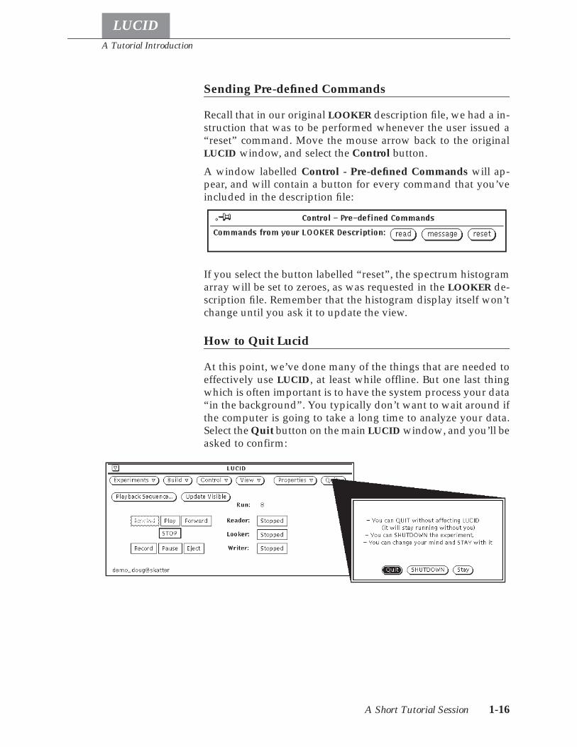
Sending Pre-defined Commands
Recall that in our original LOOKER description file, we had a in-struction that was to be performed whenever the user issued a“reset” command. Move the mouse arrow back to the originalLUCID window, and select the Control button.
A window labelled Control - Pre-defined Commands will ap-pear, and will contain a button for every command that you’veincluded in the description file:
If you select the button labelled “reset”, the spectrum histogramarray will be set to zeroes, as was requested in the LOOKER de-scription file. Remember that the histogram display itself won’tchange until you ask it to update the view.
How to Quit Lucid
At this point, we’ve done many of the things that are needed toeffectively use LUCID, at least while offline. But one last thingwhich is often important is to have the system process your data“in the background”. You typically don’t want to wait around ifthe computer is going to take a long time to analyze your data.Select the Quit button on the main LUCID window, and you’ll beasked to confirm:
A Tutorial Introduction
Where to Go from Here 1-17
LUCID
LUCID wants to know how much of the system you really wantto quit. By default, the data stream will stay running even afteryou’ve quit the LUCID program itself. This is important whensomeone else takes over the experiment from you. If the work-station computer should crash or stop, the data stream will stillkeep running without it when the experiment itself is runningelsewhere.
• Selecting the Quit button will cause the LUCID programto stop, but keep the data stream active.
• Selecting Shutdown will make LUCID shut down all ofthe data stream processes, and then quit.
• The Stay button will cancel the “alert” window, and letyou continue using LUCID.
Where to Go from Here
Now that we’ve seen how simple it is to use LUCID, you shouldgo ahead and set up a real experiment. You’re certainly welcometo “play around” with the demo experiment that was just set up,but take note that all demo experiments are periodically re-moved.
If you’re just getting started with LUCID, you should find outwhat kinds of statements the description files can contain. Theseare described in Chapters 3 and 4.
Chapter 2 describes the XLUCID program in more detail, in-cluding how to start up and administer an experi-ment. It explains how to control the READER,LOOKER and WRITER, and monitor the progress ofdata through the data stream.
Chapter 3 introduces each of the statement types that you’llneed to describe your experiment to the READER,mainly in terms of the equipment you have.
Chapter 4 explains how to set up a LOOKER description file,and describes histogramming and analysis in gener-al.
Chapter 5 talks about WRITER considerations.
Chapter 6 gives an overview of how all the pieces of LUCID fittogether.
Chapter 7 documents the many different support subroutinesand programs that may be helpful when running aLUCID experiment.
A Tutorial Introduction
Where to Go from Here 1-18
LUCID
Each section in this guide starts out with just enough informa-tion to let you use a particular feature. More details are given asyou read further into the section, so you can probably skip a lotif you’re getting started. When examples are given, LUCID key-words are printed in a “typewriter” typeface:
trigger scaler every 10 minutes
Brackets around a word indicate that the named words are op-tional.
We will assume that you’re familiar with CAMAC and the varietyof electronics that are available through it.
LUCID
2-1
Chapter
2 Using LUCID
LUCID was designed to be easy to use.
It was also designed to help experimenters think about theirwork on a higher level. As you read this manual, try to forget thedetails of your experiment, and think in more general terms.
Most experiments are quite complex in nature, and the best wayto solve the problems and get meaningful information is to de-sign the experiment from the top down: start with a very generalstatement of what you want, then break the job into a few specif-ic tasks. Each of these tasks should then be divided into jobswhich are more detailed, and this process repeated until eachtask addresses a unique detail of the experiment.
LUCID fits into the middle of this hierarchy; it only needs toknow about a few general tasks and it will worry about most ofthe details for you. For example, you should think about thephysical occurrence which will signify an “ADC event”, and notworry about how to access the ADC in the most efficient way.
Getting Started
The first thing to do is decide what you want to measure, whento make those measurements, then determine how those mea-surements will flow through LUCID and be recorded.
If you’re starting a new experiment, data will probably originatein some CAMAC equipment. You must determine how many dif-ferent event types you’ll need (an event is simply informationthat is grouped together to describe something). Some eventsmay only contain a single ADC measurement, while others cancontain as many as several thousand distinct values. The currentversion of LUCID limits an event to less than (approximately)32,000 bytes. Furthermore, the rate at which data can be acquiredis currently limited to about 245,000 bytes per second. LUCID al-lows 65535 types of events to be used in the same experiment.
Events
Using LUCID
LUCID
Getting Started 2-2
In addition to the primary data for your experiment, other eventtypes might be necessary; for example, you might want severalscaler (counter) values to be recorded at regular intervals.
A trigger simply determines when to make some measurement. Aparticle interacting with scintillation material could represent atrigger, signifying that CAMAC equipment should be read out atthat point. The next chapter describes several different ways totrigger the acquisition of event data.
In many experiments, it may not be possible to relate a uniquetrigger to every different event. For instance, you might notknow what type of interaction occurred until a bit pattern registeris examined. LUCID handles this by letting you reject the currentevent and trigger a new event after performing some tests.
The best way to get started with an experiment is to list every dif-ferent type of event the experiment will encounter, give each onea unique name, and describe how each event will be triggered.This is certainly the first step in deciding how to set up your elec-tronics, and will make the job of describing the experiment to LU-CID very easy. In the next chapter, we’ll see that in order toacquire data, LUCID just needs to know where to get the data andwhen to read it.
If you’re interacting with existing data from a previous experi-ment, things are much easier because each event type and triggerhas already been defined. You won’t have to prepare any kind ofdescription, because LUCID can extract the original descriptiondirectly from the saved data. You should at least be familiar withthe names of the variables that were used originally, on-line. Ifnot, LUCID can list them for you (see lucidview on page 7-4).
LUCID allows you to create as many “experiments” as you want.An experiment can be thought of as a data stream, as describedin the first chapter, and LUCID allows you to scan over the dataas many times as you want. In fact, you can have several differ-ent experiment names set up to look at the same data, and sever-al build names within an experiment, if you wish.
LUCID maintains a list of trusted users for each experiment. Theperson which initially creates the experiment is considered to beits administrator, and is responsible for keeping the user list upto date. See User Permissions on page 2-18.
If you want to access an experiment which has already been setup and may be currently running, make sure you know the fol-lowing things:
• The name of the computer on which the experiment wascreated.
Triggers
Administering anExperiment
Using LUCID
LUCID
The LUCID Program 2-3
• The original name of the experiment, as it was registeredwith LUCID.
• That the administrator of the experiment (the person whofirst created it) has added your name to the list of users.
If you want to create a new experiment to acquire data, makesure you:
• Get the name of the computer which is connected to yourelectronics (CAMAC equipment, for example), and makesure that the system will let you log in; your login nameand password will be the same on all computers.
• Choose a unique name for your experiment. When youfirst start up, LUCID can give you a list of all existing ex-periments on all Lab computers. If you’re just learningabout LUCID and don’t care about the name, just chooseone that isn’t already listed.
Finally, if you want to create a new experiment to analyze exist-ing data, you should:
• Find a computer which contains the data file, or the tapedrive which will read your data file.
• Choose a unique name for your experiment, as describedabove in the on-line example.
One last point about getting started: when a number of peopleare involved with an on-line experiment, it is sometimes easiestfor all involved if an experiment account is set up. This gives acommon location for all LUCID user files, and a common ac-count for controlling and monitoring the experiment. These areonly allowed for on-line experiments. If this sounds useful toyour situation, you should see the system administrator for de-tails.
The LUCID Program
At this point, you should be familiar with the tutorial given inChapter 1. The OpenWindows graphical user interface was in-troduced, and at this point we’ll assume that is what you’re us-ing, and also that you’re familiar with how to use it. If not, thereis a good on-line tutorial available, as well as documentation. Ifyou don’t have the OpenWindows interface on your worksta-tion, or you don’t have access to the documentation or on-line tu-torial, see your system administrator before continuing. Theremainder of this chapter is a reference rather than a tutorial.
Using LUCID
LUCID
Command Line Options The LUCID Program 2-4
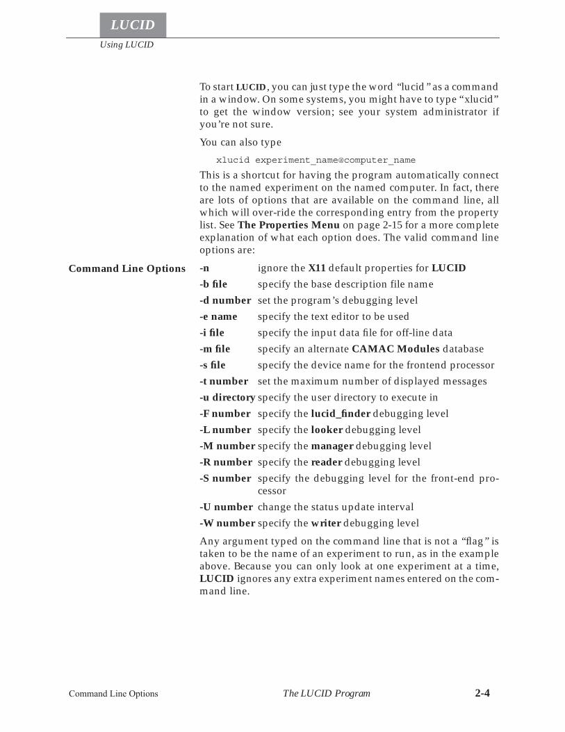
To start LUCID, you can just type the word “lucid” as a commandin a window. On some systems, you might have to type “xlucid”to get the window version; see your system administrator ifyou’re not sure.
You can also type
xlucid experiment_name@computer_name
This is a shortcut for having the program automatically connectto the named experiment on the named computer. In fact, thereare lots of options that are available on the command line, allwhich will over-ride the corresponding entry from the propertylist. See The Properties Menu on page 2-15 for a more completeexplanation of what each option does. The valid command lineoptions are:
-n ignore the X11 default properties for LUCID
-b file specify the base description file name
-d number set the program’s debugging level
-e name specify the text editor to be used
-i file specify the input data file for off-line data
-m file specify an alternate CAMAC Modules database
-s file specify the device name for the frontend processor
-t number set the maximum number of displayed messages
-u directory specify the user directory to execute in
-F number specify the lucid_finder debugging level
-L number specify the looker debugging level
-M number specify the manager debugging level
-R number specify the reader debugging level
-S number specify the debugging level for the front-end pro-cessor
-U number change the status update interval
-W number specify the writer debugging level
Any argument typed on the command line that is not a “flag” istaken to be the name of an experiment to run, as in the exampleabove. Because you can only look at one experiment at a time,LUCID ignores any extra experiment names entered on the com-mand line.
Command Line Options
Menu Buttons
Using LUCID
LUCID
The LUCID Program 2-5
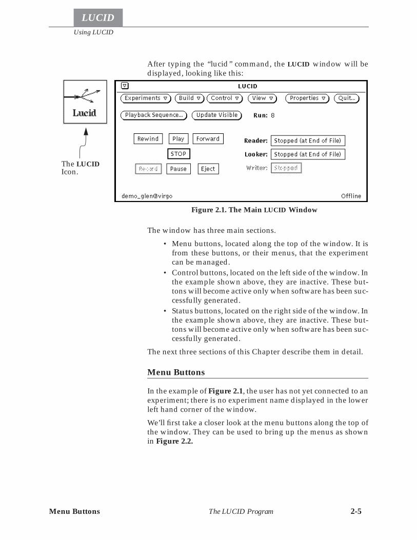
After typing the “lucid” command, the LUCID window will bedisplayed, looking like this:
The window has three main sections.
• Menu buttons, located along the top of the window. It isfrom these buttons, or their menus, that the experimentcan be managed.
• Control buttons, located on the left side of the window. Inthe example shown above, they are inactive. These but-tons will become active only when software has been suc-cessfully generated.
• Status buttons, located on the right side of the window. Inthe example shown above, they are inactive. These but-tons will become active only when software has been suc-cessfully generated.
The next three sections of this Chapter describe them in detail.
Menu Buttons
In the example of Figure 2.1, the user has not yet connected to anexperiment; there is no experiment name displayed in the lowerleft hand corner of the window.
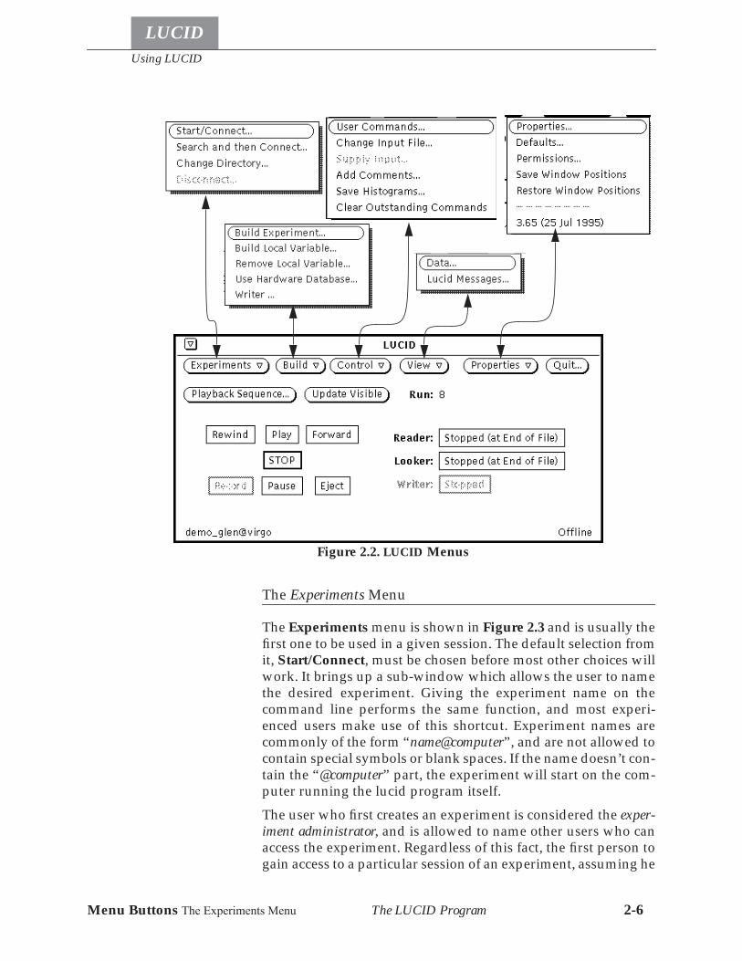
We’ll first take a closer look at the menu buttons along the top ofthe window. They can be used to bring up the menus as shownin Figure 2.2.
The LUCIDIcon.
Figure 2.1. The Main LUCID Window
Using LUCID
LUCID
Menu Buttons The Experiments Menu The LUCID Program 2-6
The Experiments Menu
The Experiments menu is shown in Figure 2.3 and is usually thefirst one to be used in a given session. The default selection fromit, Start/Connect, must be chosen before most other choices willwork. It brings up a sub-window which allows the user to namethe desired experiment. Giving the experiment name on thecommand line performs the same function, and most experi-enced users make use of this shortcut. Experiment names arecommonly of the form “name@computer”, and are not allowed tocontain special symbols or blank spaces. If the name doesn’t con-tain the “@computer” part, the experiment will start on the com-puter running the lucid program itself.
The user who first creates an experiment is considered the exper-iment administrator, and is allowed to name other users who canaccess the experiment. Regardless of this fact, the first person togain access to a particular session of an experiment, assuming he
Figure 2.2. LUCID Menus
Menu Buttons The Experiments Menu
Using LUCID
LUCID
The LUCID Program 2-7
has permission from the administrator, may use all functions de-scribed in this manual; other colleagues who subsequently con-nect to the same experiment at the same time are visitors, in thatthey are not allowed to make use of the control buttons on themain window. They are allowed to view data, and perform themost basic operations, as described later in this Chapter.
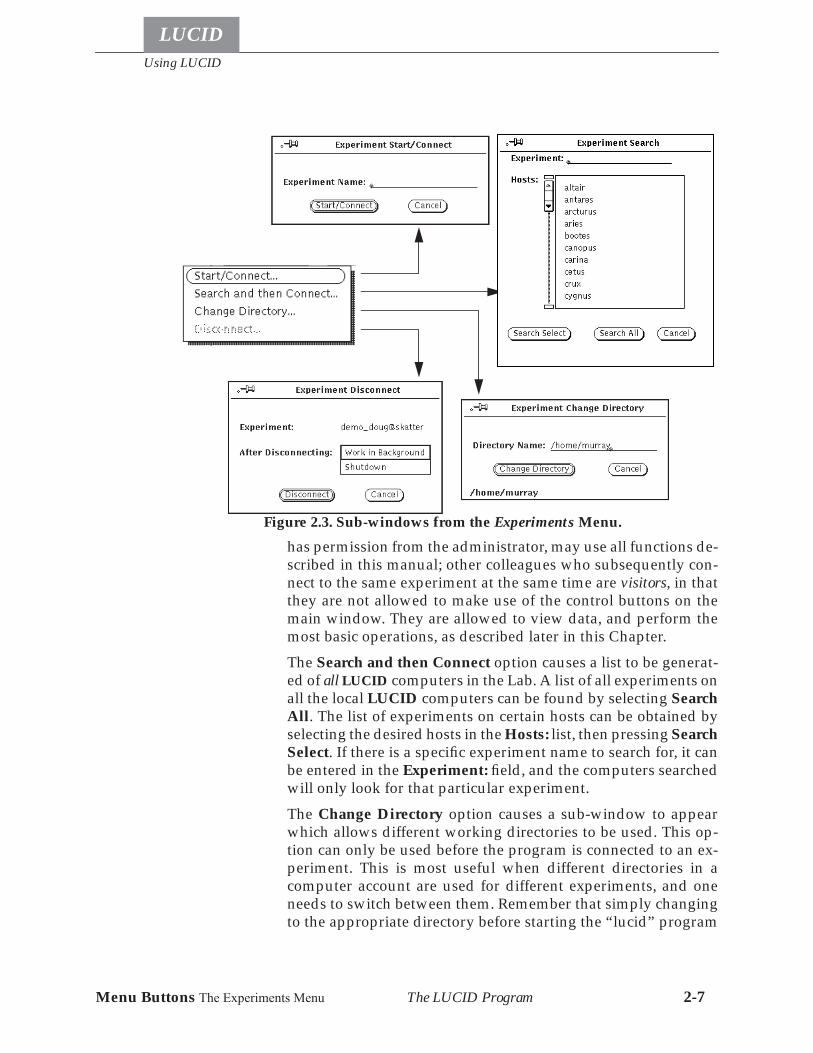
The Search and then Connect option causes a list to be generat-ed of all LUCID computers in the Lab. A list of all experiments onall the local LUCID computers can be found by selecting SearchAll. The list of experiments on certain hosts can be obtained byselecting the desired hosts in the Hosts: list, then pressing SearchSelect. If there is a specific experiment name to search for, it canbe entered in the Experiment: field, and the computers searchedwill only look for that particular experiment.
The Change Directory option causes a sub-window to appearwhich allows different working directories to be used. This op-tion can only be used before the program is connected to an ex-periment. This is most useful when different directories in acomputer account are used for different experiments, and oneneeds to switch between them. Remember that simply changingto the appropriate directory before starting the “lucid” program
Figure 2.3. Sub-windows from the Experiments Menu.
Using LUCID
LUCID
Menu Buttons The Build Menu The LUCID Program 2-8
achieves the same result, at least for the first experiment connec-tion.
The Disconnect option allows the user to disconnect from theREADER, LOOKER and/or WRITER, thereby allowing connec-tion to another experiment. The user is given the option of shut-ting down the experiment after it is disconnected; that is,terminating any of the READER, LOOKER and/or WRITER piec-es that may exist. As shown in the previous diagram, Disconnectis inactive if LUCID is not connected to an experiment.
The Build Menu
Once connected to the desired experiment, the user will typicallygo ahead to use options beneath the Build menu. This won’t bethe case if the experiment is already in progress when the con-nection was made. In such a case, someone has already built theexperiment, and the control buttons will all be active.
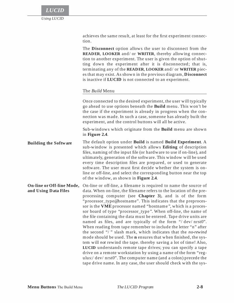
Sub-windows which originate from the Build menu are shownin Figure 2.4.
The default option under Build is named Build Experiment. Asub-window is presented which allows Editing of descriptionfiles, naming of the input file (or hardware to use if on-line), andultimately, generation of the software. This window will be usedevery time description files are prepared, or used to generatesoftware. The user must first decide whether the system is on-line or off-line, and select the corresponding button near the topof the window, as shown in Figure 2.4.
On-line or off-line, a filename is required to name the source ofdata. When on-line, the filename refers to the location of the pre-processing computer (see Chapter 3), and is of the form“processor_type@hostname”. This indicates that the preproces-sor is the VME processor named “hostname”, which is a proces-sor board of type “processor_type”. When off-line, the name ofthe file containing the data must be entered. Tape drive units arenamed as files, and are typically of the form “/dev/nrst0”.When reading from tape remember to include the letter “n” afterthe second “/” slash mark, which indicates that the no-rewindmode should be used. The n ensures that when finished, the sys-tem will not rewind the tape. thereby saving a lot of time! Also,LUCID understands remote tape drives; you can specify a tapedrive on a remote workstation by using a name of the form “reg-ulus:/dev/nrst0”. The computer name (and a colon) precede thetape drive name. In any case, the user should check with the sys-
Building the Software
On-line or Off-line Mode,and Using Data Files
Menu Buttons The Build Menu
Using LUCID
LUCID
The LUCID Program 2-9
tem administrator to determine the correct names of tape driveunits.
The user is allowed to change the input file after the software isbuilt, when off-line; see Figure 2.7 under the Change Input Fileoption for details.
The most important and time consuming step is the preparationof the experiment description files. Chapters 3 and 4 describe
Figure 2.4. Sub-windows from the Build Menu.
Using LUCID
LUCID
Menu Buttons The Build Menu The LUCID Program 2-10
what the files may contain. The description files can be preparedbeforehand, using any text editor.
The user should first select the LOOKER button if a LOOKER de-scription file is to be used. Recall that the READER is alwayspresent. Next, the user can select the appropriate Edit buttons toallow writing or modifying the descriptions. When finished, re-member to get out of the editor completely by bringing up themenu from the top border of the edit window, and choose Quit.
The user can select the button labelled Make, at the bottom of thewindow. Software will be generated and compiled. If some mis-takes were made in the description files, error and status mes-sages will be displayed; look under the View menu to displaymessages.
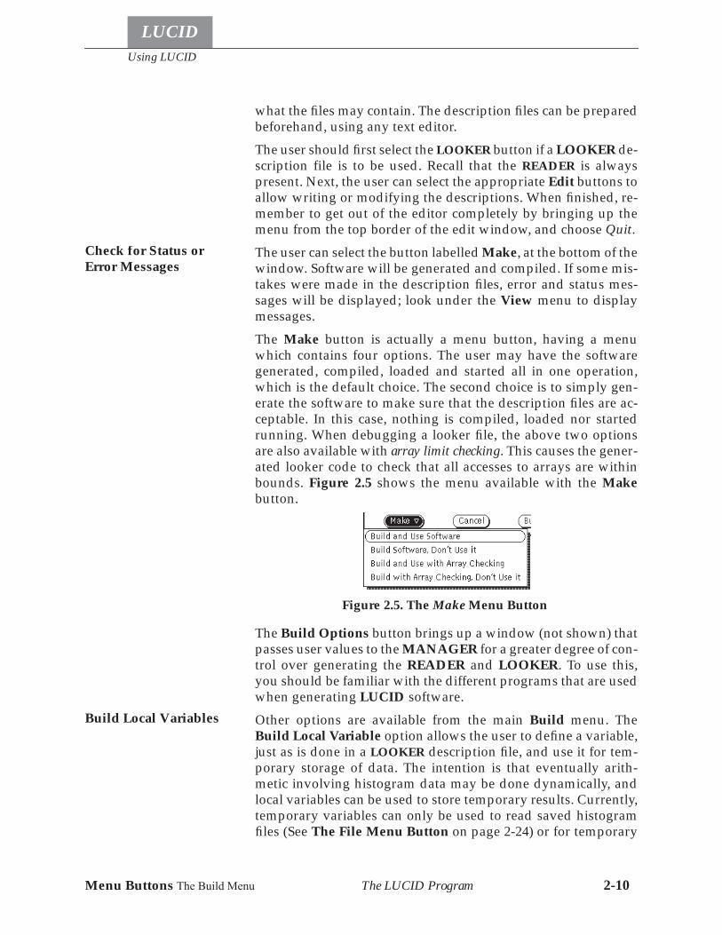
The Make button is actually a menu button, having a menuwhich contains four options. The user may have the softwaregenerated, compiled, loaded and started all in one operation,which is the default choice. The second choice is to simply gen-erate the software to make sure that the description files are ac-ceptable. In this case, nothing is compiled, loaded nor startedrunning. When debugging a looker file, the above two optionsare also available with array limit checking. This causes the gener-ated looker code to check that all accesses to arrays are withinbounds. Figure 2.5 shows the menu available with the Makebutton.
The Build Options button brings up a window (not shown) thatpasses user values to the MANAGER for a greater degree of con-trol over generating the READER and LOOKER. To use this,you should be familiar with the different programs that are usedwhen generating LUCID software.
Other options are available from the main Build menu. TheBuild Local Variable option allows the user to define a variable,just as is done in a LOOKER description file, and use it for tem-porary storage of data. The intention is that eventually arith-metic involving histogram data may be done dynamically, andlocal variables can be used to store temporary results. Currently,temporary variables can only be used to read saved histogramfiles (See The File Menu Button on page 2-24) or for temporary
Check for Status orError Messages
Figure 2.5. The Make Menu Button
Build Local Variables
Menu Buttons The Build Menu
Using LUCID
LUCID
The LUCID Program 2-11
region variables when building a new region description for ahistogram (See Region Mode on page 2-37).
The option to Remove Local Variable simply frees up the spaceassociated with temporary, local variables that have been createdby any means.
The Use Hardware Database option can be used when acquiringdata on-line, when a new READER is built, to specify differentCAMAC features than normal. Typically, a small system databaseis used to describe various features of CAMAC equipment. If de-sired, one can change these characteristics by supplying theirown database file. The format of the file is described in Appen-dix A near the end of this manual. The name of the temporarydatabase file should be set before the software is generated withthe Make button in the Build Experiment sub-window.
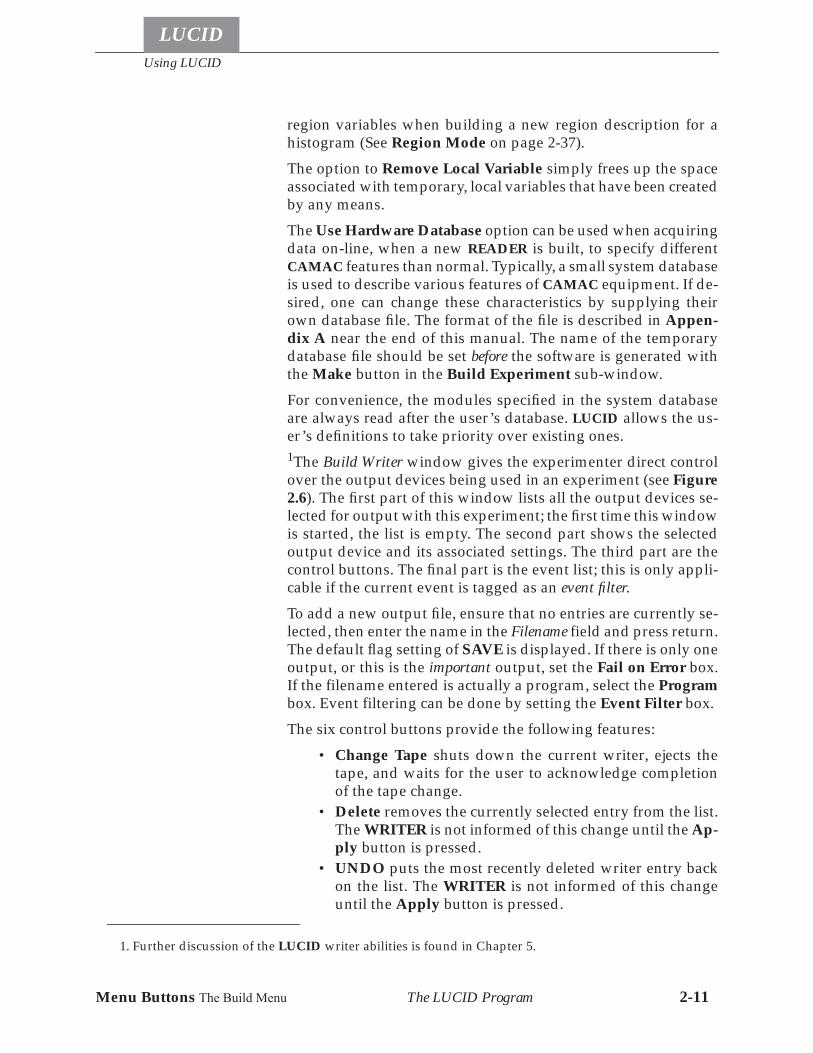
For convenience, the modules specified in the system databaseare always read after the user’s database. LUCID allows the us-er’s definitions to take priority over existing ones.1The Build Writer window gives the experimenter direct controlover the output devices being used in an experiment (see Figure2.6). The first part of this window lists all the output devices se-lected for output with this experiment; the first time this windowis started, the list is empty. The second part shows the selectedoutput device and its associated settings. The third part are thecontrol buttons. The final part is the event list; this is only appli-cable if the current event is tagged as an event filter.
To add a new output file, ensure that no entries are currently se-lected, then enter the name in the Filename field and press return.The default flag setting of SAVE is displayed. If there is only oneoutput, or this is the important output, set the Fail on Error box.If the filename entered is actually a program, select the Programbox. Event filtering can be done by setting the Event Filter box.
The six control buttons provide the following features:
• Change Tape shuts down the current writer, ejects thetape, and waits for the user to acknowledge completionof the tape change.
• Delete removes the currently selected entry from the list.The WRITER is not informed of this change until the Ap-ply button is pressed.
• UNDO puts the most recently deleted writer entry backon the list. The WRITER is not informed of this changeuntil the Apply button is pressed.
1. Further discussion of the LUCID writer abilities is found in Chapter 5.
Using LUCID
LUCID
Menu Buttons The Control Menu The LUCID Program 2-12
• Apply Changes informs the WRITER of the net changesto the file list.
• Store places the current list of output devices, and theirsettings, in your .Xdefaults file. This is automatically re-read and used as the default settings the next time Xlucidis started from the same account.
• CANCEL quits the window without applying any chang-es. The next time the window is started, it will be back tothe state that the WRITER is currently in.
The Event List shows the list of all events, and the status of theevent for the current output device. Events can be saved com-pletely, only at the output device speed, or never.1
The Control Menu
After software has been generated, the user will probably start arun by selecting the Play or Record button. All of the main con-trol buttons are described in the next section, but other less com-
1. At the time of writing this section, the Event List feature had not been implemented in the WRITER.
Figure 2.6. The Build Writer Window
Menu Buttons The Control Menu
Using LUCID
LUCID
The LUCID Program 2-13
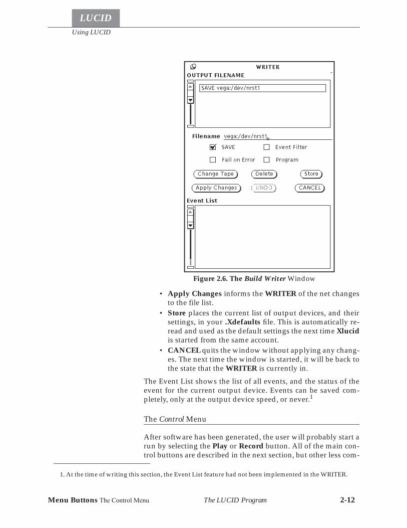
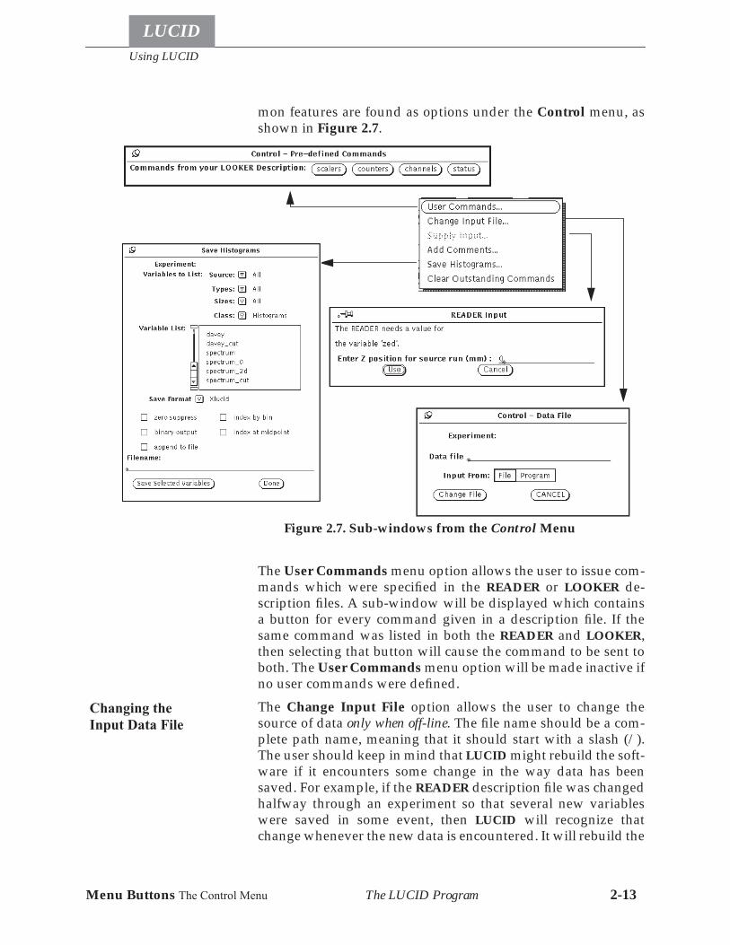
mon features are found as options under the Control menu, asshown in Figure 2.7.
The User Commands menu option allows the user to issue com-mands which were specified in the READER or LOOKER de-scription files. A sub-window will be displayed which containsa button for every command given in a description file. If thesame command was listed in both the READER and LOOKER,then selecting that button will cause the command to be sent toboth. The User Commands menu option will be made inactive ifno user commands were defined.
The Change Input File option allows the user to change thesource of data only when off-line. The file name should be a com-plete path name, meaning that it should start with a slash (/).The user should keep in mind that LUCID might rebuild the soft-ware if it encounters some change in the way data has beensaved. For example, if the READER description file was changedhalfway through an experiment so that several new variableswere saved in some event, then LUCID will recognize thatchange whenever the new data is encountered. It will rebuild the
Figure 2.7. Sub-windows from the Control Menu
Changing theInput Data File
Using LUCID
LUCID
Menu Buttons The View Menu The LUCID Program 2-14
software to accommodate the changes and tell you about it. In-put can also come from a program directly to the READER whenoff-line. This might happen when comparing acquired data todata from a simulation program.
If a description file was set up to ask the user for input at somepoint, then LUCID will stop the data flow, and bring up a win-dow asking for the appropriate value. This happens automatical-ly, and the experiment won’t continue until the input is supplied.LUCID allows you to bring up the input window again, in case itwas accidentally dismissed. The user can select the Supply In-put option to redisplay the window, but the option itself will beinactive if there is not input expected at that time.
The LUCID data stream allows comment records to be inserted.Selecting Add Comments brings up a text window (not shown)into which the user can enter a comment, and then have the com-ment record entered into the data stream. This only works whenon-line.
The Clear Outstanding Commands tells LUCID to forget aboutever getting a response to a command sent to the READER orLOOKER. This should only be used when LUCID refuses to runnew commands for the user. At this point, it is usual that theLOOKER or READER have failed already.
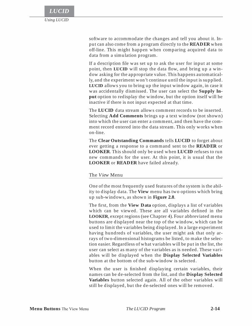
The View Menu
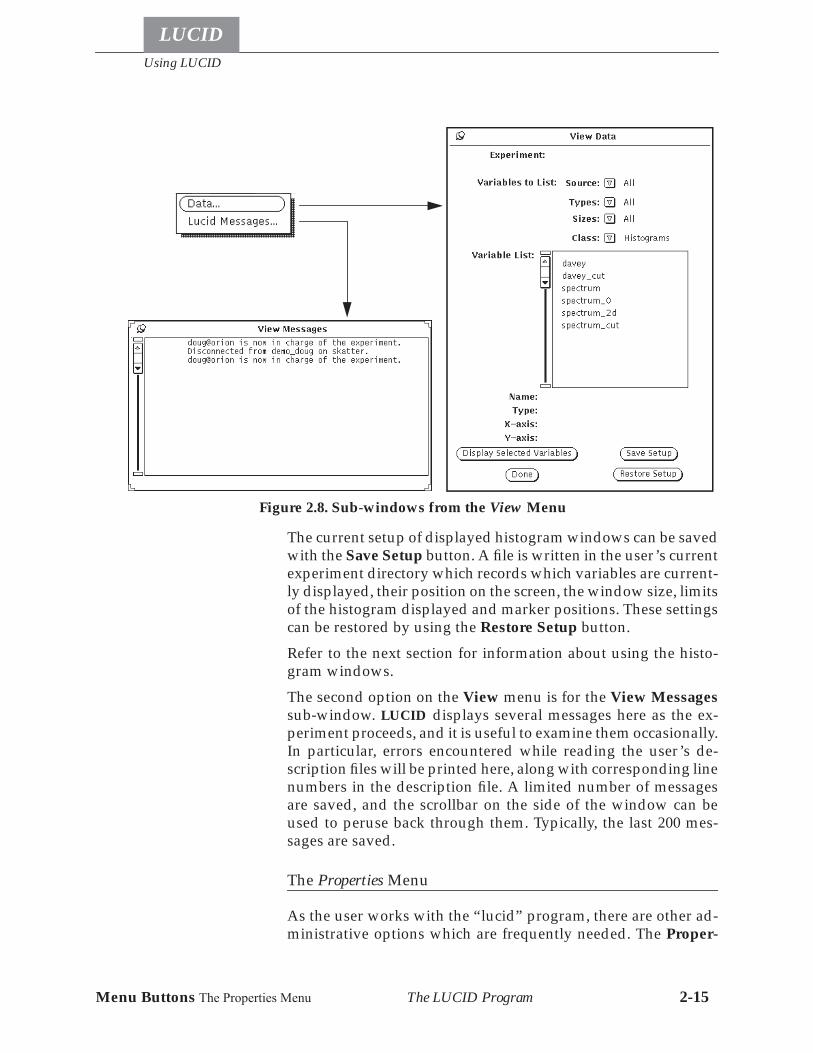
One of the most frequently used features of the system is the abil-ity to display data. The View menu has two options which bringup sub-windows, as shown in Figure 2.8.
The first, from the View Data option, displays a list of variableswhich can be viewed. These are all variables defined in theLOOKER, except regions (see Chapter 4). Four abbreviated menubuttons are displayed near the top of the window, which can beused to limit the variables being displayed. In a large experimenthaving hundreds of variables, the user might ask that only ar-rays of two-dimensional histograms be listed, to make the selec-tion easier. Regardless of what variables will be put in the list, theuser can select as many of the variables as is needed. These vari-ables will be displayed when the Display Selected Variablesbutton at the bottom of the sub-window is selected.
When the user is finished displaying certain variables, theirnames can be de-selected from the list, and the Display SelectedVariables button selected again. All of the other variables willstill be displayed, but the de-selected ones will be removed.
Menu Buttons The Properties Menu
Using LUCID
LUCID
The LUCID Program 2-15
The current setup of displayed histogram windows can be savedwith the Save Setup button. A file is written in the user’s currentexperiment directory which records which variables are current-ly displayed, their position on the screen, the window size, limitsof the histogram displayed and marker positions. These settingscan be restored by using the Restore Setup button.
Refer to the next section for information about using the histo-gram windows.
The second option on the View menu is for the View Messagessub-window. LUCID displays several messages here as the ex-periment proceeds, and it is useful to examine them occasionally.In particular, errors encountered while reading the user’s de-scription files will be printed here, along with corresponding linenumbers in the description file. A limited number of messagesare saved, and the scrollbar on the side of the window can beused to peruse back through them. Typically, the last 200 mes-sages are saved.
The Properties Menu
As the user works with the “lucid” program, there are other ad-ministrative options which are frequently needed. The Proper-
Figure 2.8. Sub-windows from the View Menu
Using LUCID
LUCID
Menu Buttons The Properties Menu The LUCID Program 2-16
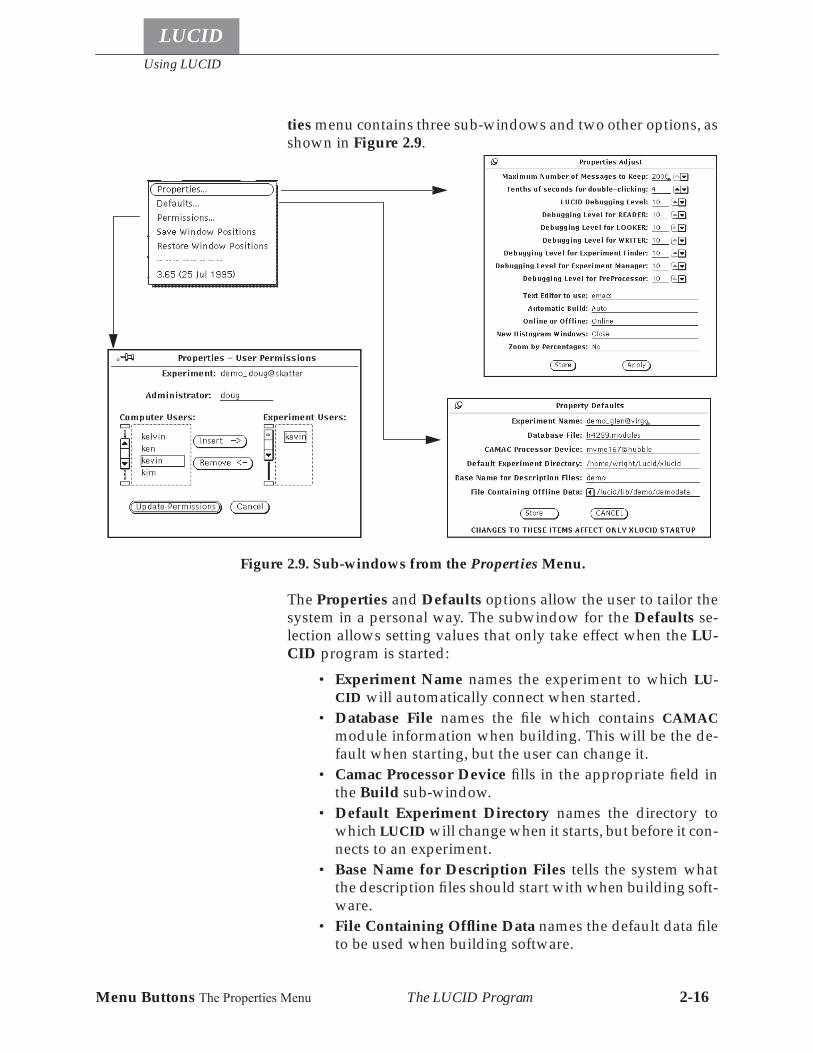
ties menu contains three sub-windows and two other options, asshown in Figure 2.9.
The Properties and Defaults options allow the user to tailor thesystem in a personal way. The subwindow for the Defaults se-lection allows setting values that only take effect when the LU-CID program is started:
• Experiment Name names the experiment to which LU-CID will automatically connect when started.
• Database File names the file which contains CAMACmodule information when building. This will be the de-fault when starting, but the user can change it.
• Camac Processor Device fills in the appropriate field inthe Build sub-window.
• Default Experiment Directory names the directory towhich LUCID will change when it starts, but before it con-nects to an experiment.
• Base Name for Description Files tells the system whatthe description files should start with when building soft-ware.
• File Containing Offline Data names the default data fileto be used when building software.
Figure 2.9. Sub-windows from the Properties Menu.
Menu Buttons The Properties Menu
Using LUCID
LUCID
The LUCID Program 2-17
The fields in the Properties Adjust window are effective imme-diately when changed.
• Maximum Number of Messages to Keep determines thesize of the memory for the View Messages sub-window.It can be set to a very large number, if the user wants tosee lots of output messages.
• Tenths of Seconds for double-clicking can be set to alarge value for users who can’t or don’t want to double-click the mouse buttons quickly. The value is typically 3or 4, but 10 would allow a 1 second delay between subse-quent clicks. This delay is used in conjunction with thehistogram windows, discussed in the next section.
• LUCID Debugging Level can be adjusted for 7 differentparts of the system. It is used mostly by system adminis-trators or programmers to determine problems withinthe system. Changing these numbers cause messages tobe displayed which describe what the system is doing.The numbers can be thought of as thresholds, so that a val-ue of 10 or more allows no extra messages to be printed.A value of 9 will cause a few extra status messages tocome up, 8 will bring up even more, and so forth. BEWARNED that setting any of these values to a low num-ber will cause a lot of output to be generated. For exam-ple, if the debugging level of the “manager” was set to 0,the simple action of building an experiment could gener-ate a dozen pages of output.
• Text Editor to Use instructs the system which text editoryou want to use when making (or changing) descriptionfiles. It can be set to LUCID, emacs, edt or vi. If edt or vi ischosen, the system will start a terminal sub-window inwhich to run the editor.
• Automatic Build can be set to true or false; this allows thesystem to build the experiment automatically when itconnects to an experiment which hasn’t be built yet.
• Online or Offline selects the default state to be used inthe Build sub-window, and hence the operating mode forthe experiment.
• New Histogram Windows can be set to Open or Close todetermine the status of newly displayed histogram win-dows.
• Zoom by Percentages affects the ZOOM buttons on thehistogram window (See The Histogram Windows onpage 2-23). If set to Yes, the windows zoom by a stepsizepercentage, otherwise the windows zoom by a stepsizeamount.
Using LUCID
LUCID
Menu Buttons The Quit Button The LUCID Program 2-18
The user must select the Store button to ensure that the changedproperties will stay in effect next time the system is used.
The User Permissions sub-window allows the user to check onthe names of colleagues which are allowed access to the experi-ment. The window lists all valid users on the computer systems,as well as the users of the experiment. If the current user is theexperiment’s administrator (that is, the one who created the ex-periment), then the list can be changed. The setup allows movingnames from the computer’s user list over to the experiment’suser list. Names can also be deleted from the experiment’s userlist completely. The creator of the experiment can also name anyother user as the administrator by typing the new name into theappropriate field at the top of the sub-window, as seen in Figure2.9. The anybody special user name allows any user to access theexperiment. This is helpful when there is more than one personinvolved in running an experiment.
The options to Save and Restore Window Positions can be usedto tailor the look of lucid on the screen, when it is started. Sub-windows should be moved and resized as desired, and thentheir positions saved. They will be restored to these positionsand sizes when lucid is next started. This does not save the char-acteristics of histogram windows (The View Menu on page 2-14describes how to save histogram windows).
The Quit Button
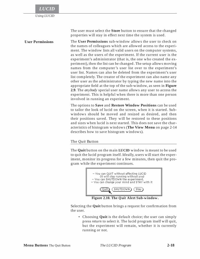
The Quit button on the main LUCID window is meant to be usedto quit the lucid program itself. Ideally, users will start the exper-iment, monitor its progress for a few minutes, then quit the pro-gram while the experiment continues.
Selecting the Quit button brings a request for confirmation fromthe user.
• Choosing Quit is the default choice; the user can simplypress return to select it. The lucid program itself will quit,but the experiment will remain, whether it is currentlyrunning or not.
User Permissions
Figure 2.10. The Quit Alert Sub-window.
Control Buttons
Using LUCID
LUCID
The LUCID Program 2-19
• The Shutdown button will cause the READER, LOOKERand WRITER to finish the current run if necessary, quitand close down the experiment completely until nexttime.
• The Stay option tells LUCID to keep working as if nothinghas happened.
If lucid is not connected to an experiment, a simple yes/no confir-mation is asked for.
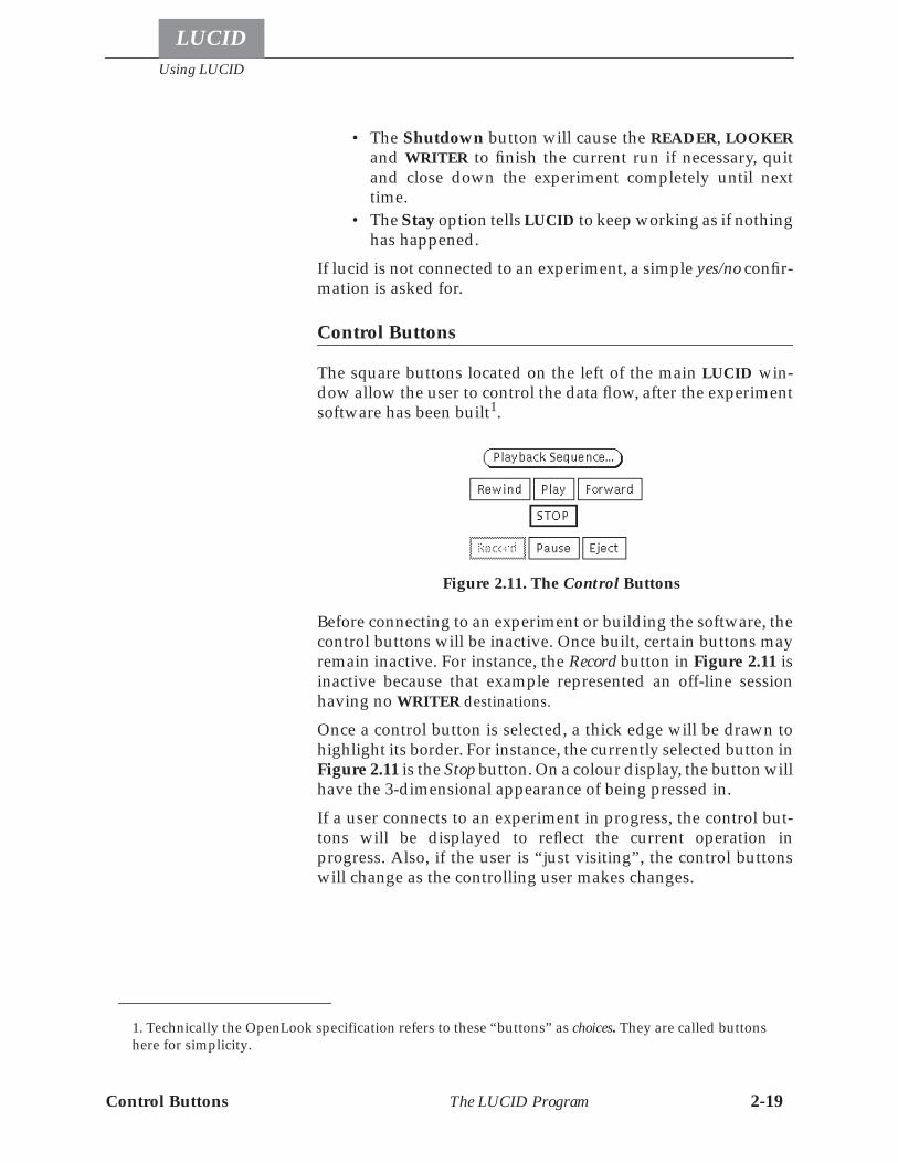
Control Buttons
The square buttons located on the left of the main LUCID win-dow allow the user to control the data flow, after the experimentsoftware has been built1.
Before connecting to an experiment or building the software, thecontrol buttons will be inactive. Once built, certain buttons mayremain inactive. For instance, the Record button in Figure 2.11 isinactive because that example represented an off-line sessionhaving no WRITER destinations.
Once a control button is selected, a thick edge will be drawn tohighlight its border. For instance, the currently selected button inFigure 2.11 is the Stop button. On a colour display, the button willhave the 3-dimensional appearance of being pressed in.If a user connects to an experiment in progress, the control but-tons will be displayed to reflect the current operation inprogress. Also, if the user is “just visiting”, the control buttonswill change as the controlling user makes changes.
1. Technically the OpenLook specification refers to these “buttons” as choices. They are called buttonshere for simplicity.
Figure 2.11. The Control Buttons
Using LUCID
LUCID
Control Buttons The Record Button The LUCID Program 2-20
The Record Button
When the user requests that a WRITER be present in the experi-ment, the Record button will be made active. In such a case, theRewind button will not be usable, since LUCID wants to write anordered sequence of runs to the output.A Run is started when the Record button is selected; the currentrun number is displayed near the top right-center of the mainwindow. Every time the Record button is selected, the run num-ber will be automatically incremented.If no WRITER is present, the Record button will be inactive, andthe Play button can be used to start the next run.
The Play Button
The Play button can be selected to begin a new run. It will onlybe usable when data is not being saved, such as when analyzingdata off-line, or testing electronics or detectors on-line.If the system is off-line, the Play button will remain highlighteduntil all data has been processed; the Stop button will then be-come highlighted and the Play button returned to normal.If only certain runs are required to be analyzed off-line, the usermay select the Programmed Playback button.
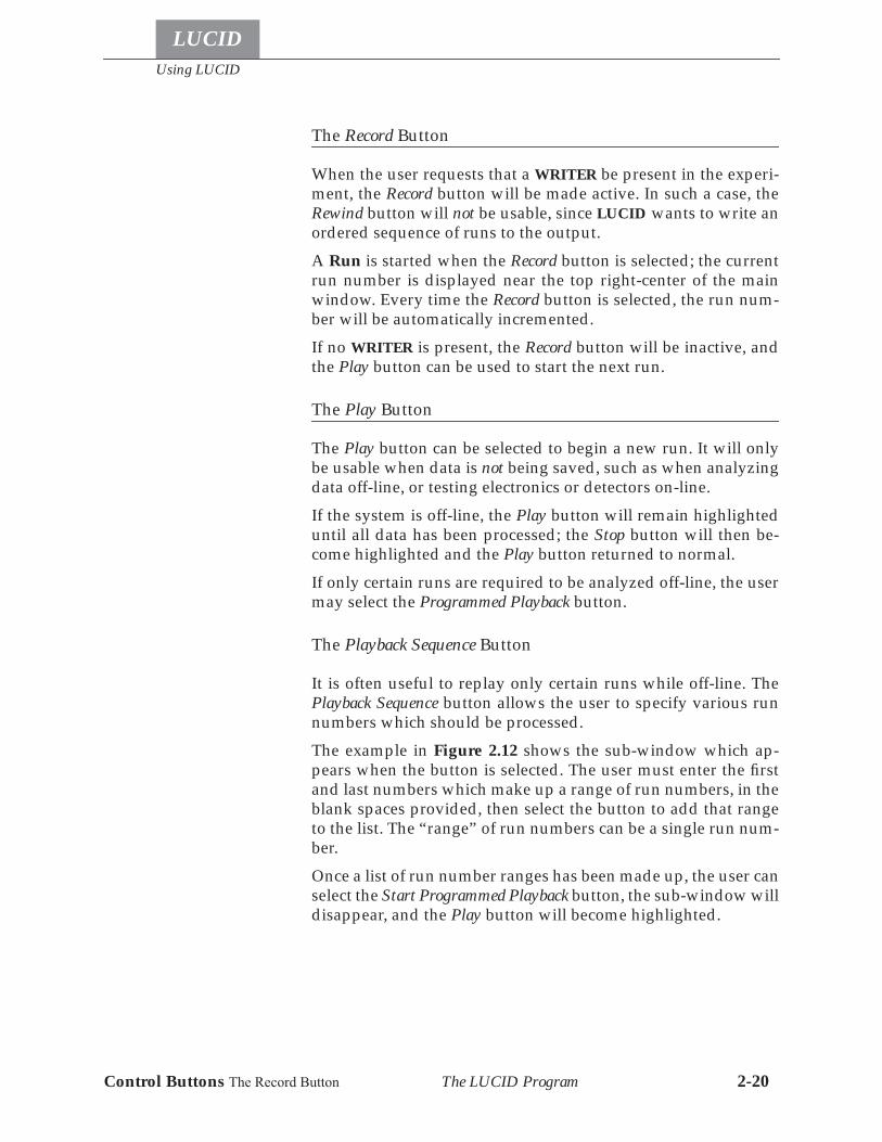
The Playback Sequence Button
It is often useful to replay only certain runs while off-line. ThePlayback Sequence button allows the user to specify various runnumbers which should be processed.The example in Figure 2.12 shows the sub-window which ap-pears when the button is selected. The user must enter the firstand last numbers which make up a range of run numbers, in theblank spaces provided, then select the button to add that rangeto the list. The “range” of run numbers can be a single run num-ber.Once a list of run number ranges has been made up, the user canselect the Start Programmed Playback button, the sub-window willdisappear, and the Play button will become highlighted.
Control Buttons The Playback Sequence Button
Using LUCID
LUCID
The LUCID Program 2-21
The Pause Button
If the user wants to suspend the run temporarily, the Pause but-ton may be selected. A blinking message will be displayed acrossthe window to remind the user that the run is suspended.To resume the run, the user need select the Pause button a secondtime, or re-select the button which was previously highlighted,such as the Play or Record button.The Pause button will work whether the system is on-line or off.
The Stop Button
To stop processing the current run, on-line or off, the user mayselect the Stop button.
The Rewind Button
If the current session is off-line, the Rewind button may be select-ed. It simply rewinds the input data file to the beginning. This istrue for tapes or regular disk files.If a WRITER is present and ac-tive, a warning message is displayed.
Figure 2.12. The Playback Sequence Window
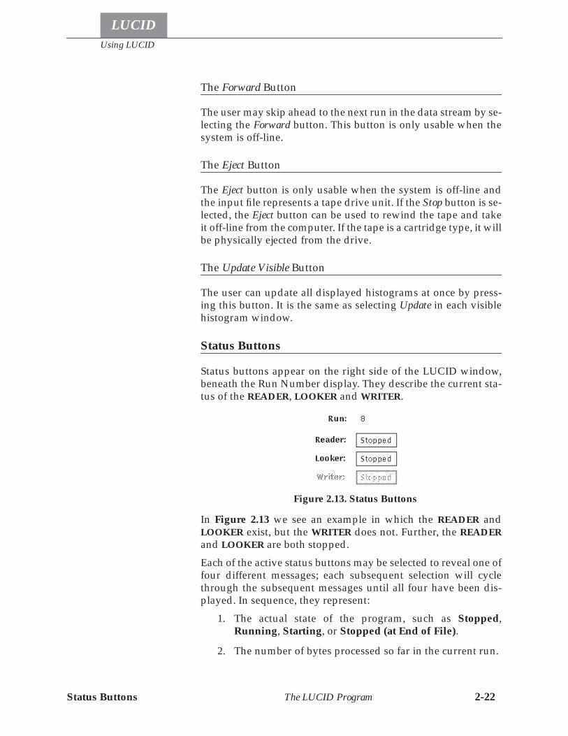
Using LUCID
LUCID
Status Buttons The LUCID Program 2-22
The Forward Button
The user may skip ahead to the next run in the data stream by se-lecting the Forward button. This button is only usable when thesystem is off-line.
The Eject Button
The Eject button is only usable when the system is off-line andthe input file represents a tape drive unit. If the Stop button is se-lected, the Eject button can be used to rewind the tape and takeit off-line from the computer. If the tape is a cartridge type, it willbe physically ejected from the drive.
The Update Visible Button
The user can update all displayed histograms at once by press-ing this button. It is the same as selecting Update in each visiblehistogram window.
Status Buttons
Status buttons appear on the right side of the LUCID window,beneath the Run Number display. They describe the current sta-tus of the READER, LOOKER and WRITER.
In Figure 2.13 we see an example in which the READER andLOOKER exist, but the WRITER does not. Further, the READERand LOOKER are both stopped.Each of the active status buttons may be selected to reveal one offour different messages; each subsequent selection will cyclethrough the subsequent messages until all four have been dis-played. In sequence, they represent:
1. The actual state of the program, such as Stopped,Running, Starting, or Stopped (at End of File).
2. The number of bytes processed so far in the current run.
Figure 2.13. Status Buttons
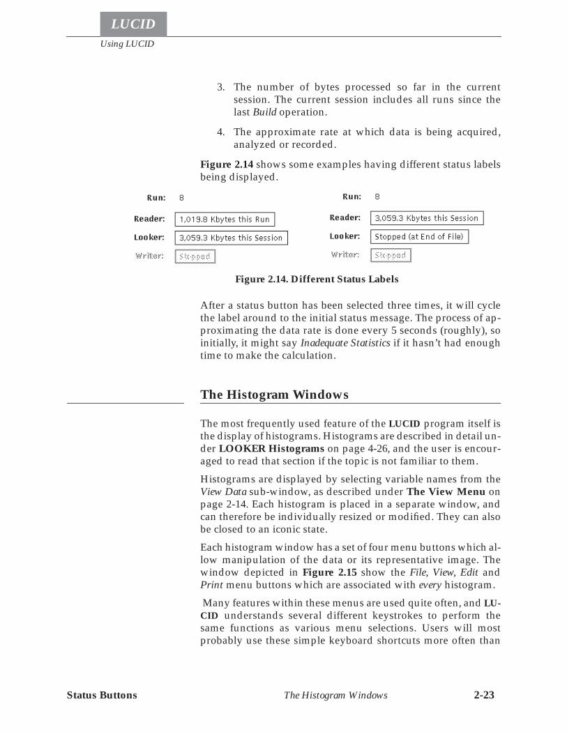
Status Buttons
Using LUCID
LUCID
The Histogram Windows 2-23
3. The number of bytes processed so far in the currentsession. The current session includes all runs since thelast Build operation.
4. The approximate rate at which data is being acquired,analyzed or recorded.
Figure 2.14 shows some examples having different status labelsbeing displayed.
After a status button has been selected three times, it will cyclethe label around to the initial status message. The process of ap-proximating the data rate is done every 5 seconds (roughly), soinitially, it might say Inadequate Statistics if it hasn’t had enoughtime to make the calculation.
The Histogram Windows
The most frequently used feature of the LUCID program itself isthe display of histograms. Histograms are described in detail un-der LOOKER Histograms on page 4-26, and the user is encour-aged to read that section if the topic is not familiar to them.Histograms are displayed by selecting variable names from theView Data sub-window, as described under The View Menu onpage 2-14. Each histogram is placed in a separate window, andcan therefore be individually resized or modified. They can alsobe closed to an iconic state.Each histogram window has a set of four menu buttons which al-low manipulation of the data or its representative image. Thewindow depicted in Figure 2.15 show the File, View, Edit andPrint menu buttons which are associated with every histogram. Many features within these menus are used quite often, and LU-CID understands several different keystrokes to perform thesame functions as various menu selections. Users will mostprobably use these simple keyboard shortcuts more often than
Figure 2.14. Different Status Labels
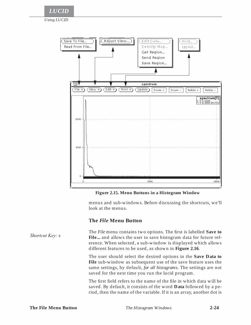
Using LUCID
LUCID
The File Menu Button The Histogram Windows 2-24
menus and sub-windows. Before discussing the shortcuts, we’lllook at the menus.
The File Menu Button
The File menu contains two options. The first is labelled Save toFile... and allows the user to save histogram data for future ref-erence. When selected, a sub-window is displayed which allowsdifferent features to be used, as shown in Figure 2.16.The user should select the desired options in the Save Data toFile sub-window as subsequent use of the save feature uses thesame settings, by default, for all histograms. The settings are notsaved for the next time you run the lucid program.The first field refers to the name of the file in which data will besaved. By default, it consists of the word Data followed by a pe-riod, then the name of the variable. If it is an array, another dot is
Figure 2.15. Menu Buttons in a Histogram Window
Shortcut Key: s
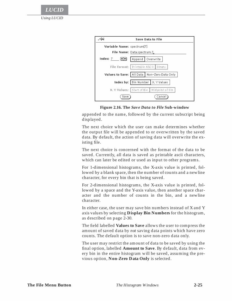
The File Menu Button
Using LUCID
LUCID
The Histogram Windows 2-25
appended to the name, followed by the current subscript beingdisplayed.The next choice which the user can make determines whetherthe output file will be appended to or overwritten by the saveddata. By default, the action of saving data will overwrite the ex-isting file.The next choice is concerned with the format of the data to besaved. Currently, all data is saved as printable ascii characters,which can later be edited or used as input to other programs.For 1-dimensional histograms, the X-axis value is printed, fol-lowed by a blank space, then the number of counts and a newlinecharacter, for every bin that is being saved.For 2-dimensional histograms, the X-axis value is printed, fol-lowed by a space and the Y-axis value, then another space char-acter and the number of counts in the bin, and a newlinecharacter.In either case, the user may save bin numbers instead of X and Yaxis values by selecting Display Bin Numbers for the histogram,as described on page 2-30.The field labelled Values to Save allows the user to compress theamount of saved data by not saving data points which have zerocounts. The default option is to save non-zero data only.The user may restrict the amount of data to be saved by using thefinal option, labelled Amount to Save. By default, data from ev-ery bin in the entire histogram will be saved, assuming the pre-vious option, Non-Zero Data Only is selected.
Figure 2.16. The Save Data to File Sub-window
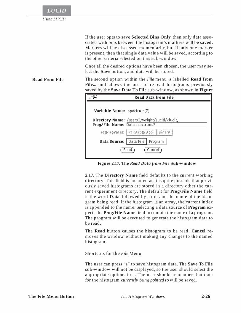
Using LUCID
LUCID
The File Menu Button The Histogram Windows 2-26
If the user opts to save Selected Bins Only, then only data asso-ciated with bins between the histogram’s markers will be saved.Markers will be discussed momentarily, but if only one markeris present, then that single data value will be saved, according tothe other criteria selected on this sub-window.Once all the desired options have been chosen, the user may se-lect the Save button, and data will be stored.The second option within the File menu is labelled Read fromFile... and allows the user to re-read histograms previouslysaved by the Save Data To File sub-window, as shown in Figure
2.17. The Directory Name field defaults to the current workingdirectory. This field is included as it is quite possible that previ-ously saved histograms are stored in a directory other the cur-rent experiment directory. The default for Prog/File Name fieldis the word Data, followed by a dot and the name of the histo-gram being read. If the histogram is an array, the current indexis appended to the name. Selecting a data source of Program ex-pects the Prog/File Name field to contain the name of a program.The program will be executed to generate the histogram data tobe read.The Read button causes the histogram to be read. Cancel re-moves the window without making any changes to the namedhistogram.
Shortcuts for the File Menu
The user can press “s” to save histogram data. The Save To Filesub-window will not be displayed, so the user should select theappropriate options first. The user should remember that datafor the histogram currently being pointed to will be saved.
Read From File
Figure 2.17. The Read Data from File Sub-window
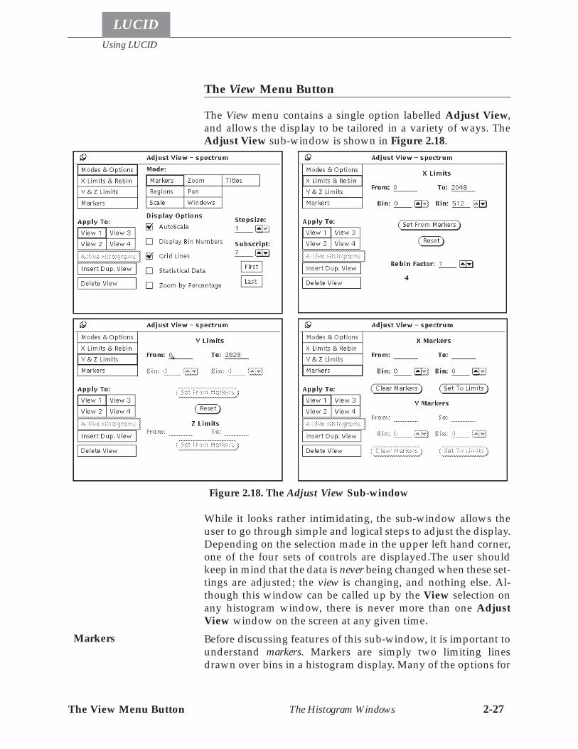
The View Menu Button
Using LUCID
LUCID
The Histogram Windows 2-27
The View Menu Button
The View menu contains a single option labelled Adjust View,and allows the display to be tailored in a variety of ways. TheAdjust View sub-window is shown in Figure 2.18.
While it looks rather intimidating, the sub-window allows theuser to go through simple and logical steps to adjust the display.Depending on the selection made in the upper left hand corner,one of the four sets of controls are displayed.The user shouldkeep in mind that the data is never being changed when these set-tings are adjusted; the view is changing, and nothing else. Al-though this window can be called up by the View selection onany histogram window, there is never more than one AdjustView window on the screen at any given time.Before discussing features of this sub-window, it is important tounderstand markers. Markers are simply two limiting linesdrawn over bins in a histogram display. Many of the options for
Figure 2.18. The Adjust View Sub-window
Markers
Using LUCID
LUCID
The View Menu Button The Histogram Windows 2-28
adjusting the display use markers. When drawn on the display,a marker occupies the same width as the bin over which it isplaced. Markers are discussed in more detail on page 2-32, andagain on page 2-35.In the Adjust View sub-window, the first set of choices allowsthe user to attach different meanings to mouse actions and key-strokes. By default, the system is in Marker Mode, as described be-low. Using the mouse buttons and keypad is discussed in moredetail under Shortcuts for the View Menu on page 2-32, but it isimportant to realize that different modes will cause the system toreact differently to commands.
• Marker Mode causes the mouse pointer and buttons toaffect the markers on the screen. The keypad on the rightside of the keyboard also becomes used to locate markersin this mode. This is the most common mode for interact-ing with the display.
• Region Mode causes the user input to adjust Regions,which are discussed under Histogram Regions on page4-33. Briefly, adjusting regions on the display will allowyour analysis to perform different instructions. At thetime of writing this document, the Region Mode is oper-ational for 1-dimensional histograms only.
• Scale Mode causes the mouse pointer and other controlsto change the scale of the displayed data; for 1-dimension-al histograms, user actions will adjust the height of thebin data (the Y-axis) being displayed.
• Zoom Mode allows the user to use mouse buttons andkeystrokes to affect the viewed limits of the display, andeffectively enlarge a particular area of interest.
• Pan Mode causes the mouse and keypad to change thearea of the histogram being viewed. The user is allowedto easily “pan across” the data.
• Window Mode (or Border Mode) is not currently imple-mented.
• Title Mode allows the user to adjust the position of thehistogram title within the display, or add new titles.
Using these different modes is described in more detail on page2-34.Each histogram window can be split into several sub-views ofthe same data. Each sub-view is independently controllable, sothat the user can view different parts of the same histogram, asshown in Figure 2.19. As mentioned below, the user can alsoview different subscripted histograms of the same array usingsub-views.
Histogram Sub-Views
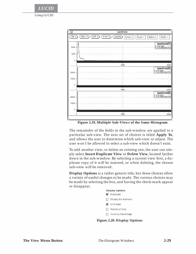
The View Menu Button
Using LUCID
LUCID
The Histogram Windows 2-29
The remainder of the fields in the sub-window are applied to aparticular sub-view. The next set of choices is titled Apply To,and allows the user to determine which sub-view to adjust. Theuser won’t be allowed to select a sub-view which doesn’t exist.To add another view, or delete an existing one, the user can sim-ply select Insert Duplicate View or Delete View, located fartherdown in the sub-window. By selecting a current view first, a du-plicate copy of it will be inserted, or when deleting, the chosensub-view will be removed.Display Options is a rather generic title, but these choices allowa variety of useful changes to be made. The various choices maybe made by selecting the box, and having the check-mark appearor disappear.
Figure 2.19. Multiple Sub-Views of the Same Histogram
Figure 2.20. Display Options
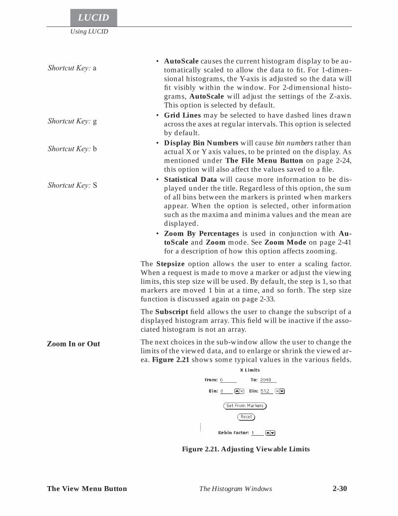
Using LUCID
LUCID
The View Menu Button The Histogram Windows 2-30
• AutoScale causes the current histogram display to be au-tomatically scaled to allow the data to fit. For 1-dimen-sional histograms, the Y-axis is adjusted so the data willfit visibly within the window. For 2-dimensional histo-grams, AutoScale will adjust the settings of the Z-axis.This option is selected by default.
• Grid Lines may be selected to have dashed lines drawnacross the axes at regular intervals. This option is selectedby default.
• Display Bin Numbers will cause bin numbers rather thanactual X or Y axis values, to be printed on the display. Asmentioned under The File Menu Button on page 2-24,this option will also affect the values saved to a file.
• Statistical Data will cause more information to be dis-played under the title. Regardless of this option, the sumof all bins between the markers is printed when markersappear. When the option is selected, other informationsuch as the maxima and minima values and the mean aredisplayed.
• Zoom By Percentages is used in conjunction with Au-toScale and Zoom mode. See Zoom Mode on page 2-41for a description of how this option affects zooming.
The Stepsize option allows the user to enter a scaling factor.When a request is made to move a marker or adjust the viewinglimits, this step size will be used. By default, the step is 1, so thatmarkers are moved 1 bin at a time, and so forth. The step sizefunction is discussed again on page 2-33.The Subscript field allows the user to change the subscript of adisplayed histogram array. This field will be inactive if the asso-ciated histogram is not an array.The next choices in the sub-window allow the user to change thelimits of the viewed data, and to enlarge or shrink the viewed ar-ea. Figure 2.21 shows some typical values in the various fields.
Shortcut Key: a
Shortcut Key: g
Shortcut Key: b
Shortcut Key: S
Zoom In or Out
Figure 2.21. Adjusting Viewable Limits
The View Menu Button
Using LUCID
LUCID
The Histogram Windows 2-31
The X Limits may be set to any values within the extents of thehistogram, and the area delimited by these values will be re-drawn to fill the entire window. Bin values may also be set, or ad-justed by selecting the up-down arrow buttons; again the areaenclosed between these values will be redrawn to fill the win-dow. These values apply only to the current sub-view, if morethan 1 exists. If a value is entered for X or Y axis values, it will berounded to the nearest bin boundary.The button labelled Set From Markers may be selected to allowzooming in to the area enclosed between markers on the display.For the Y-axis limits of a 1-D histogram, the button labelled SetFrom Markers performs a slightly different function: the extentsof the Y-axis are set to match the extent of the data values in thearea between the markers. This essentially sets the Y-axis limitsso that data between the markers will fill the display.When a 2-dimensional histogram is being viewed, the Y-axis lim-its button labelled Set From Markers will perform exactly thesame function as the button does for the X-axis. Further, the but-ton labelled Set From Markers for the Z-axis is usable, and willset the Z-axis limits to the limits of the data contained within themarked area.If the user adjusts the Y limits for a 1-D histogram, or the Z limitsfor a 2-D histogram, the Autoscale option is turned off automat-ically. Values below the from: limit are drawn as being at thefrom: limit, and values above the to: limit are drawn as being atthe to: limit. Set From Markers for these axes will copy the highvalue from within the area delimited by the markers.The Reset buttons allow the user to easily reset the limits to theirdefault, full scale values.The Rebin Factor provides a simple dynamic integer rebinningfacility for XLUCID. The bin width indicates the number of Xaxis bins that are summed to obtain the bin height. When rebin-ning, the actual bins displayed will be adjusted to start the firstbin on an even multiple of the rebin factor. For example, with ahistogram displayed with no rebinning, and the first displayedbin being 12: if a rebinning value of 5 were used, then the histo-gram would now start at bin 2 which would be made up of theoriginal bins 10 to 14. The display is also adjusted so the last binis made up of a number of original bins equal to the rebinningfactor, and the last displayed bin would include the last shownbin number from the original histogram display.Currently, when histograms are scaled, panned, or zoomed, the cal-culations for the start and end positions are based on the original
Rebinning
Using LUCID
LUCID
The View Menu Button The Histogram Windows 2-32
bin numbers. Setting the step size to the rebin factor will makethese functions behave as if they had a bin size of 1.Rebinning is not yet available for 2-dimensional histograms.The final set of values in the sub-window allows positioning themarkers within a sub-view. Values are entered for them in thesame way as for limits. Any value within the extents of the his-togram may be used, but the system will round the value, if nec-essary, to a value on a bin boundary. Using the Bin fields willavoid confusion, since they are always whole numbers and al-ways aligned on a bin boundary. Marker values need not bewithin the current limits for X/Y axes, they will be positioned onthe correct bins, but just not visible on the display.Pressing Clear Markers simply removes the corresponding X orY markers from the display. Double-clicking on a histogram inMarker mode clears both the X and the Y markers.The Set To Limits button allows the user to set markers at thecurrent limits of the viewed data. That is, markers will be placedon the first and last bins which are currently visible in the sub-view.With a 2-dimensional histogram, markers appear visually as apair of lines, one marking an X-axis bin and the other marking aY-axis bin. The result is that only 1 bin is selected, as representedby the intersection point of these two lines. An area between twomarkers is therefore the rectangle enclosed by the four lines, asshown in Figure 2.22. The data within the bins of a 2-dimension-al histogram are represented on the screen as smaller rectangleswhich are filled to various degrees. For instance, if a bin con-tained as much or more data as specified by the upper Z-axislimit, then the bin’s rectangle would appear to be filled. If the bincontained very little data as compared to the lower limit, thenthe bin‘s rectangle would be empty. A rectangle which containsa filled area of 50% means that the bin contains roughly half thedata which the Z-axis limits include.
Shortcuts for the View Menu
There are several shortcuts which the user can make, allowingquick adjustment of the view. First, the four display options canbe changed by pressing single characters on the keyboard.An upper or lower-case “a” will turn on the autoscale option.Another one will turn the option off.Pressing an upper or lower-case “b” will enable or disable Dis-play Bin Numbers in a similar fashion.
Adjusting Markers
Representing 2-DHistograms Visually
AutoScale
Display Bin Numbers
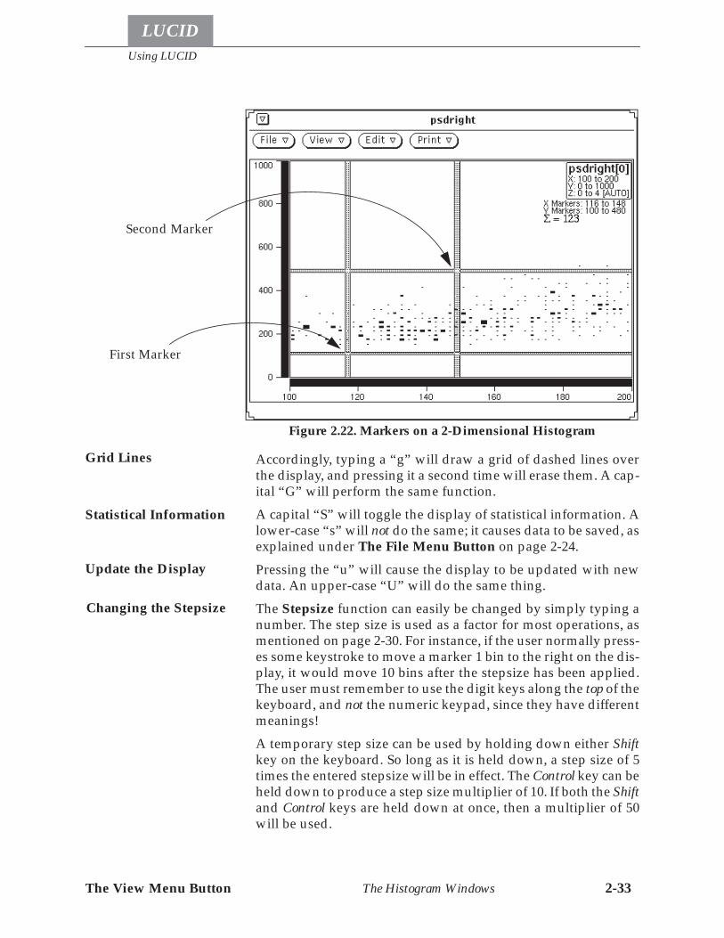
The View Menu Button
Using LUCID
LUCID
The Histogram Windows 2-33
Accordingly, typing a “g” will draw a grid of dashed lines overthe display, and pressing it a second time will erase them. A cap-ital “G” will perform the same function.A capital “S” will toggle the display of statistical information. Alower-case “s” will not do the same; it causes data to be saved, asexplained under The File Menu Button on page 2-24.Pressing the “u” will cause the display to be updated with newdata. An upper-case “U” will do the same thing.The Stepsize function can easily be changed by simply typing anumber. The step size is used as a factor for most operations, asmentioned on page 2-30. For instance, if the user normally press-es some keystroke to move a marker 1 bin to the right on the dis-play, it would move 10 bins after the stepsize has been applied.The user must remember to use the digit keys along the top of thekeyboard, and not the numeric keypad, since they have differentmeanings!A temporary step size can be used by holding down either Shiftkey on the keyboard. So long as it is held down, a step size of 5times the entered stepsize will be in effect. The Control key can beheld down to produce a step size multiplier of 10. If both the Shiftand Control keys are held down at once, then a multiplier of 50will be used.
Figure 2.22. Markers on a 2-Dimensional Histogram
First Marker
Second Marker
Grid Lines
Statistical Information
Update the Display
Changing the Stepsize
Using LUCID
LUCID
The View Menu Button The Histogram Windows 2-34
The most useful shortcuts involve adjusting the view, by usingthe mouse buttons in conjunction with the numeric keypad onthe right side of the keyboard. As described on page 2-28, thecurrent mode of the program will affect how certain keystrokesare interpreted. The mode of the program may be changed quiteeasily by selecting various function keys, located along the top ofthe keyboard. None of the keyboard shortcuts mentioned thusfar are affected, but the shortcuts involving the view, as men-tioned below, depend entirely on the current mode.Rather than selecting the current mode from the Adjust Viewsub-window, the user may press the following function keys:
Mode Function KeyMarker F2Region F3Scale F4Zoom F5Pan F6
Window F7Title F8
When a mode is selected, a reminder will be displayed in thelower left corner of the histogram window currently being point-ed to. The mode remains in effect for all histograms, until anothermode is selected.The user may also specify a temporary mode change, so thatonly the current keystroke will be performed in the desiredmode. For example, the user will most often work in markermode, but by performing an extra keystroke, zoom mode can beenabled temporarily to perform one command. Temporarymode changes will be discussed near the end of this section.Some keys on the numeric keypad keep the same meaning re-gardless of mode; we’ll consider them first. Figure 2.23 showsthe layout of the keypad.The insert and delete keys at the bottom of the keypad will insertand delete sub-views from histograms, respectively. The func-tion of these buttons doesn’t change from one mode to another;they can always be used to change the number of sub-views. Themouse pointer must be pointing to the histogram sub-viewwhich is to be duplicated or deleted.
Marker Mode
This is the most commonly used operating mode, and is the de-fault when the program starts.
Select the Current Mode
Insert or DeleteSub-Views
Shortcut Key: F2

The View Menu Button
Using LUCID
LUCID
The Histogram Windows 2-35
Markers may be placed by simply selecting a bin in the histogramdisplay; the first marker must be placed by clicking the left-mostmouse button, while pointing at the appropriate bin. While hold-
ing the mouse button down, the pointer may be draggedthrough various bins until the correct one is highlighted. Oncepositioned, the title of the histogram will display the position ofthe marker. If bin numbers are being displayed (see DISPLAYOPTIONS on page 2-29) the bin number containing the markerwill be shown instead.
7Home
4
1End
8
5
2
9PgUp
6
3PgDn
0Ins
•Del
Figure 2.23. Layout of the Numeric Keypad
Left mouse buttonplaces the first marker
Middle mouse buttonplaces the second marker
Figure 2.24. Placing Markers with the Mouse
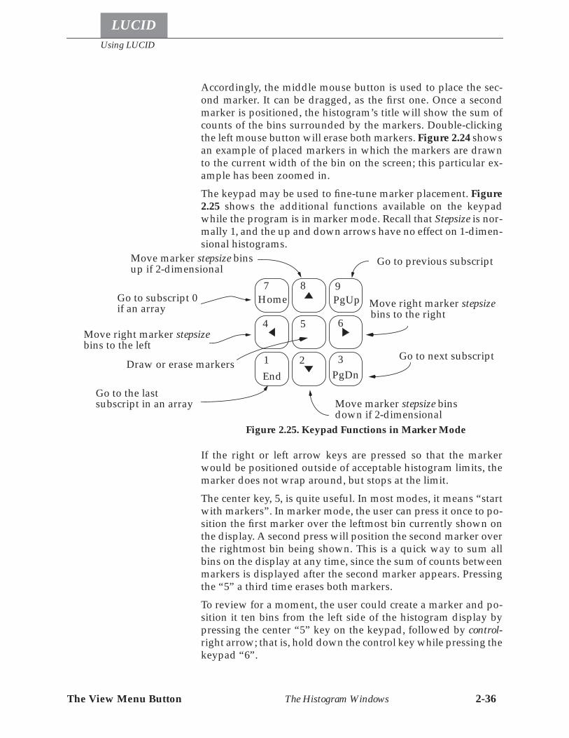
Using LUCID
LUCID
The View Menu Button The Histogram Windows 2-36
Accordingly, the middle mouse button is used to place the sec-ond marker. It can be dragged, as the first one. Once a secondmarker is positioned, the histogram’s title will show the sum ofcounts of the bins surrounded by the markers. Double-clickingthe left mouse button will erase both markers. Figure 2.24 showsan example of placed markers in which the markers are drawnto the current width of the bin on the screen; this particular ex-ample has been zoomed in.The keypad may be used to fine-tune marker placement. Figure2.25 shows the additional functions available on the keypadwhile the program is in marker mode. Recall that Stepsize is nor-mally 1, and the up and down arrows have no effect on 1-dimen-sional histograms.
If the right or left arrow keys are pressed so that the markerwould be positioned outside of acceptable histogram limits, themarker does not wrap around, but stops at the limit.The center key, 5, is quite useful. In most modes, it means “startwith markers”. In marker mode, the user can press it once to po-sition the first marker over the leftmost bin currently shown onthe display. A second press will position the second marker overthe rightmost bin being shown. This is a quick way to sum allbins on the display at any time, since the sum of counts betweenmarkers is displayed after the second marker appears. Pressingthe “5” a third time erases both markers.To review for a moment, the user could create a marker and po-sition it ten bins from the left side of the histogram display bypressing the center “5” key on the keypad, followed by control-right arrow; that is, hold down the control key while pressing thekeypad “6”.
7Home
4
1End
8
5
2
9PgUp
6
3PgDn
Figure 2.25. Keypad Functions in Marker Mode
Move right marker stepsizebins to the right
Move right marker stepsizebins to the left
Move marker stepsize binsdown if 2-dimensional
Move marker stepsize binsup if 2-dimensional
Draw or erase markers
Go to previous subscript
Go to next subscript
Go to subscript 0if an array
Go to the lastsubscript in an array
The View Menu Button
Using LUCID
LUCID
The Histogram Windows 2-37
The Home and End keys will cause the first and last subscriptedhistograms in an array to be displayed, respectively. Pressing thePage Down (PgDn) key will cause the next subscript to be dis-played. For instance, if spectrum[0] is being displayed, the PageDown key will cause spectrum[1] to be shown. The user canthink of this as “going down through the array”, since we usual-ly visualize an array as a vertical stack of subscripted items.When the last subscript is reached, pressing the Page Down but-ton again will cycle the subscript back up to 0.Correspondingly, the Page Up button (PgUp) will “go up in thearray”; the previous subscript will be shown until 0 is reached,then wrap around to the bottom of the array again.
Region Mode
The arrow keys can be used to position limits of regions, in muchthe same way as markers.The most apparent difference betweenregions and markers is multiple areas for regions, requiring aconcept of a selected region area. The selected area is the only partof the current region that is affected by keyboard or mouse com-mands.Region mode is only useful if a region has been attached to thecurrent histogram by the Get Region... menu selection. The binsincluded in the region of a 1D histogram are indicated by shad-ing the background of the histogram. The region bins in a 2D his-togram are outlined. The selected area is “ghosted” to providevisual differentiation.Adjusting a region can be done completely with the mousepointer and buttons. Clicking the left mouse button once on anarea selects that area. The selected area can be dragged left orright by holding the left button down after making a selection,and then moving the mouse left or right. If an area has been se-lected, pressing the middle mouse button adjusts the left edge ofthe area to the current bin, and the right mouse button adjuststhe right edge of the area to the current bin. Double clicking theleft mouse pointer does one of four different things, dependingon where the pointer is. If the pointer is between the markers, thebins between the markers (inclusive) are added to the region ifnot all the bins are currently in the region. If all bins between themarkers are already part of the region, the bins between themarkers are removed from the region. If the pointer is outsidethe markers, and the bin under the pointer is not in the region,the bin is added to the region. If the pointer is over an area out-side the markers, the area is removed from the region.
Shortcut Key: F3
1D Regions

Using LUCID
LUCID
The View Menu Button The Histogram Windows 2-38
With 2D regions, there are three types of objects to work with: se-
Selected Area Unselected Area Limits of theSelected Area
Figure 2.26. Viewing 1D Regions
2D Regions
Figure 2.27. Viewing 2D Regions
Selected AreaUnselected Area Polygon
The View Menu Button
Using LUCID
LUCID
The Histogram Windows 2-39
lected areas, unselected areas, and polygons. An area is a groupof one or more adjacent bins, and the outline follows the borderof the bins. Polygons are user-drawn lines, and go from screenpoint to screen point, ignoring bin boundaries; see Figure 2.27.Polygons are drawn on the screen to fill or empty an area. Draw-ing a polygon is done by pressing the SELECT button when thepointer is outside of any region area, then moving the pointer tothe next location and pressing again, and continuing until allpoints have been selected. Pressing the 5 key on the numeric key-pad causes the area within the polygon to become a selected area.Pressing 5 a second time causes the area to be cleared. If a mis-take is made when drawing, the ADJUST button erases the cur-rent polygon.Unselected areas cannot be modified directly, but must bechanged into a selected area by placing the pointer over it andpressing the SELECT button.A selected area can be moved around the screen with the four ar-row keys. If the selected area is shifted beyond the limits of thehistogram, the edge of the selected area will fall off! A selectedarea can also be dragged by selecting an area and not releasingthe SELECT button, then moving the mouse. Releasing the SE-LECT button stops the dragging. Be warned that the screen up-dates more moving an area can be quite slow, and it can takemany tens of seconds for XLUCID to catch up with drawing thedragged area!The CUT key deletes all selected areas. The COPY key creates anunselected area at the same location as each selected area. ThePASTE key unselects all selected areas.Changes made to a region do not take effect in the looker untilSend Region is selected from the histogram menu.Regions can also be adjusted using the keypad, although thiscurrently provides less functionality than the mouse. Keypadfunctions for 1 dimensional histograms are shown in Figure 2.28,and keypad functions for 2D histograms are shown in Figure2.28.
Scale Mode
Scale mode can be used to zoom in on the data. This mode is thesame as zoom mode for 1-dimensional histograms. For 2-dimen-sional histograms, scale mode allows the user to adjust the scaleof the data; that is, to adjust the Z-axis. Figure 2.30 describes thefunctions available from the keypad while in scale mode.
Send Region
Shortcut Key: F4
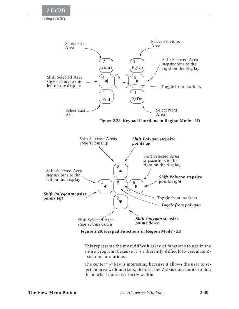
Using LUCID
LUCID
The View Menu Button The Histogram Windows 2-40
This represents the most difficult array of functions to use in theentire program, because it is inherently difficult to visualize Z-axis transformations.The center “5” key is interesting because it allows the user to se-lect an area with markers, then set the Z-axis data limits so thatthe marked data fits exactly within.
7Home
4 5
9PgUp
6
3PgDn
1End
Figure 2.28. Keypad Functions in Region Mode - 1D
Select FirstArea
Select LastArea
Select PreviousArea
Select NextArea
Shift Selected Areastepsize bins to theright on the display
Shift Selected Areastepsize bins to theleft on the display Toggle from markers
4
8
5
2
6
Figure 2.29. Keypad Functions in Region Mode - 2D
Shift Selected Areastepsize bins to theright on the display
Shift Selected Areastepsize bins to theleft on the display
Shift Selected Areasstepsize bins up
Shift Selected Areastepsize bins down
Toggle from markersToggle from polygon
Shift Polygon stepsizepoints up
Shift Polygon stepsizepoints right
Shift Polygon stepsizepoints left
Shift Polygon stepsizepoints down
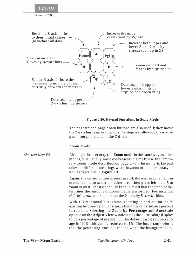
The View Menu Button
Using LUCID
LUCID
The Histogram Windows 2-41
The page up and page down buttons are also useful; they movethe Z-axis limits up or down by the stepsize, allowing the user topan through the data in the Z direction.
Zoom Mode
Although the user may run Zoom mode in the same way as othermodes, it is usually most convenient to simply use the tempo-rary zoom mode described on page 2-43. The numeric keypadtakes on different meanings when in zoom mode, temporary ornot, as described in Figure 2.31.Again, the center button is most useful; the user may remain inmarker mode to select a marker area, then press left-meta-5 tozoom in on it. The user should keep in mind that the stepsize de-termines the amount of zoom that is performed. For instance,shift-left arrow will zoom in on the X-axis by 5⋅stepsize bins.With 1-Dimensional histograms, zooming in and out on the Y-axis can be done by either stepsize bin units or by stepsize percentincrements. Selecting the Zoom by Percentage and AutoScaleoptions on the Adjust View window sets the autoscaling displayto be a percentage of maximum. The default displayed percent-age is 100%, this can be reduced to 1%. The important point isthat the percentage does not change when the histogram is up-
7Home
4
8
5
2
9PgUp
6
3PgDn
Figure 2.30. Keypad Functions in Scale Mode
Increase the upperZ-axis limit by stepsize
Decrease the upperZ-axis limit by stepsize
Reset the Z-axis limitsto their initial values(to include all data)
Zoom out of X andY axes by stepsize bins
Zoom in on X andY axes by stepsize bins
Increase both upper andlower Z-axis limits bystepsize (pan up in Z)
Decrease both upper andlower Z-axis limits bystepsize (pan down in Z)
Set the Z-axis limits to themaxima and minima of datacurrently between the markers
Shortcut Key: F5
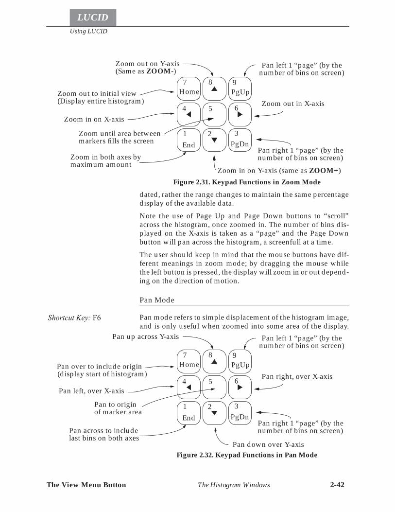
Using LUCID
LUCID
The View Menu Button The Histogram Windows 2-42
dated, rather the range changes to maintain the same percentagedisplay of the available data.Note the use of Page Up and Page Down buttons to “scroll”across the histogram, once zoomed in. The number of bins dis-played on the X-axis is taken as a “page” and the Page Downbutton will pan across the histogram, a screenfull at a time.The user should keep in mind that the mouse buttons have dif-ferent meanings in zoom mode; by dragging the mouse whilethe left button is pressed, the display will zoom in or out depend-ing on the direction of motion.
Pan Mode
Pan mode refers to simple displacement of the histogram image,and is only useful when zoomed into some area of the display.
7Home
4
1End
8
5
2
9PgUp
6
3PgDn
Figure 2.31. Keypad Functions in Zoom Mode
Zoom out in X-axis
Zoom in on X-axis
Zoom in on Y-axis (same as ZOOM+)
Zoom out on Y-axis
Zoom until area between
Pan left 1 “page” (by the
Pan right 1 “page” (by the
Zoom out to initial view
Zoom in both axes by
number of bins on screen)
markers fills the screen
maximum amount
(Display entire histogram)
number of bins on screen)
(Same as ZOOM-)
Shortcut Key: F6
7Home
4
1End
8
5
2
9PgUp
6
3PgDn
Figure 2.32. Keypad Functions in Pan Mode
Pan right, over X-axis
Pan left, over X-axis
Pan down over Y-axis
Pan up across Y-axis
Pan to origin
Pan left 1 “page” (by the
Pan right 1 “page” (by the
Pan over to include origin
Pan across to include
number of bins on screen)
(display start of histogram)
number of bins on screen)
of marker area
last bins on both axes
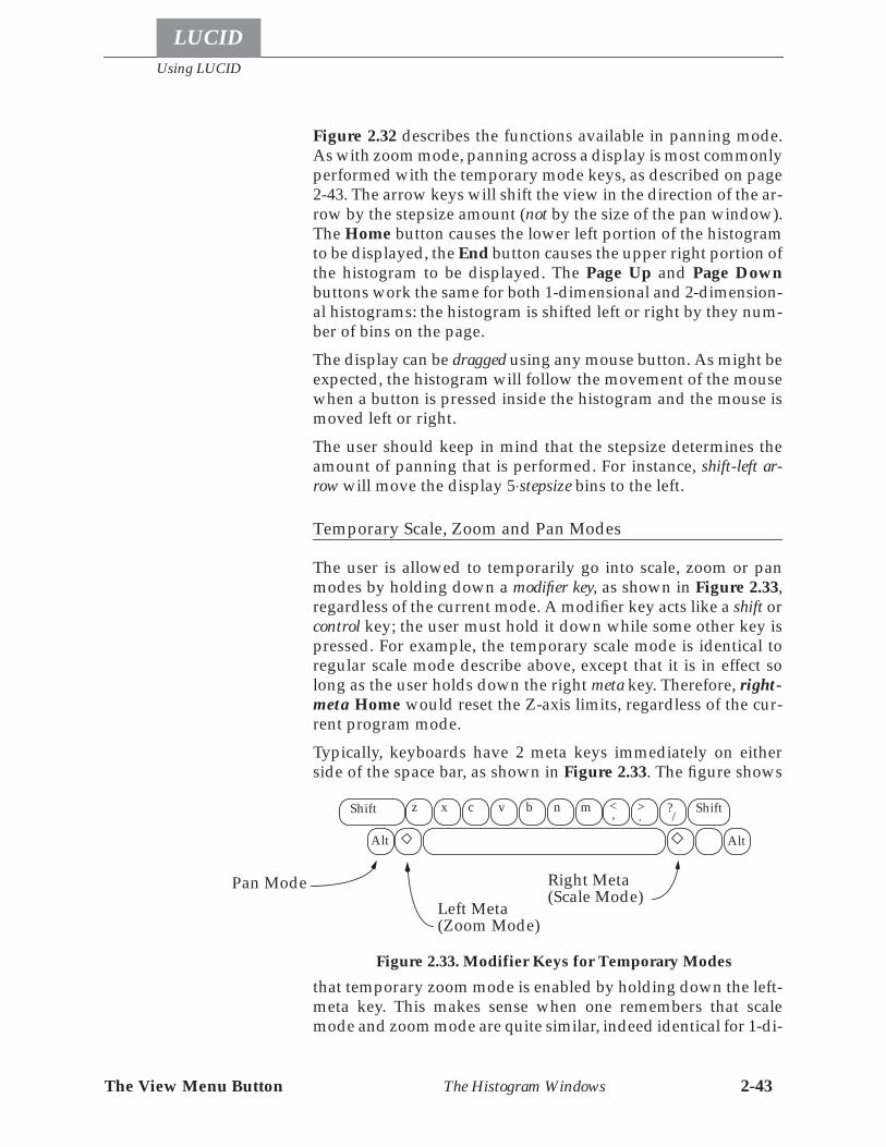
The View Menu Button
Using LUCID
LUCID
The Histogram Windows 2-43
Figure 2.32 describes the functions available in panning mode.As with zoom mode, panning across a display is most commonlyperformed with the temporary mode keys, as described on page2-43. The arrow keys will shift the view in the direction of the ar-row by the stepsize amount (not by the size of the pan window).The Home button causes the lower left portion of the histogramto be displayed, the End button causes the upper right portion ofthe histogram to be displayed. The Page Up and Page Downbuttons work the same for both 1-dimensional and 2-dimension-al histograms: the histogram is shifted left or right by they num-ber of bins on the page.The display can be dragged using any mouse button. As might beexpected, the histogram will follow the movement of the mousewhen a button is pressed inside the histogram and the mouse ismoved left or right.The user should keep in mind that the stepsize determines theamount of panning that is performed. For instance, shift-left ar-row will move the display 5⋅stepsize bins to the left.
Temporary Scale, Zoom and Pan Modes
The user is allowed to temporarily go into scale, zoom or panmodes by holding down a modifier key, as shown in Figure 2.33,regardless of the current mode. A modifier key acts like a shift orcontrol key; the user must hold it down while some other key ispressed. For example, the temporary scale mode is identical toregular scale mode describe above, except that it is in effect solong as the user holds down the right meta key. Therefore, right-meta Home would reset the Z-axis limits, regardless of the cur-rent program mode.Typically, keyboards have 2 meta keys immediately on eitherside of the space bar, as shown in Figure 2.33. The figure shows
that temporary zoom mode is enabled by holding down the left-meta key. This makes sense when one remembers that scalemode and zoom mode are quite similar, indeed identical for 1-di-
z x c v b n m , . /< > ?Shift Shift
AltAlt
Right Meta(Scale Mode)
Left Meta(Zoom Mode)
Pan Mode
Figure 2.33. Modifier Keys for Temporary Modes
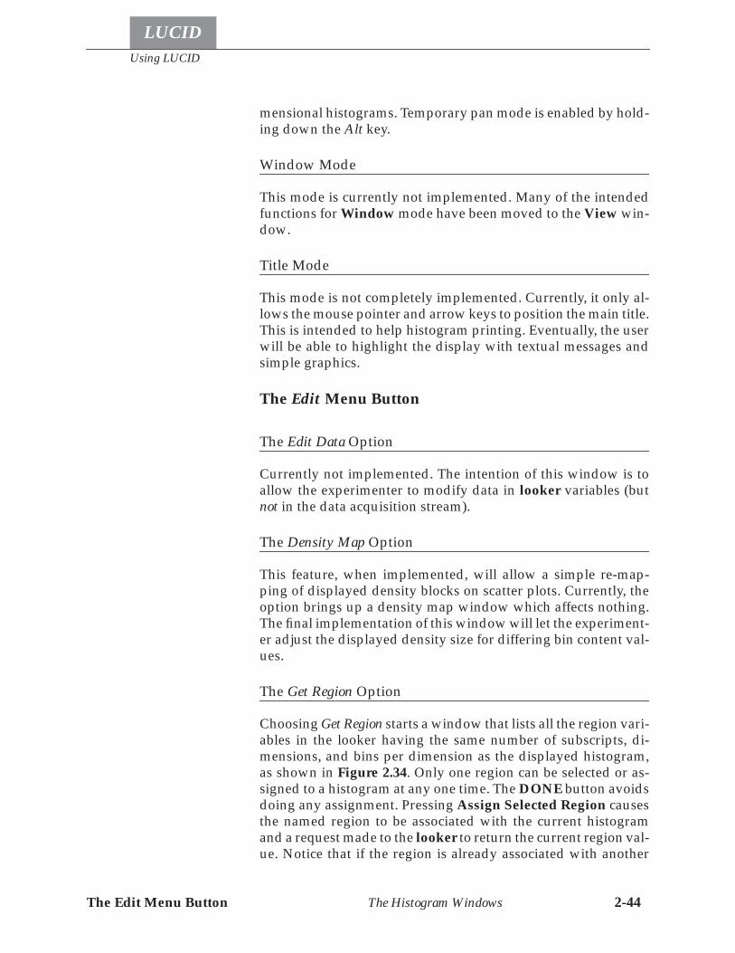
Using LUCID
LUCID
The Edit Menu Button The Histogram Windows 2-44
mensional histograms. Temporary pan mode is enabled by hold-ing down the Alt key.
Window Mode
This mode is currently not implemented. Many of the intendedfunctions for Window mode have been moved to the View win-dow.
Title Mode
This mode is not completely implemented. Currently, it only al-lows the mouse pointer and arrow keys to position the main title.This is intended to help histogram printing. Eventually, the userwill be able to highlight the display with textual messages andsimple graphics.
The Edit Menu Button
The Edit Data Option
Currently not implemented. The intention of this window is toallow the experimenter to modify data in looker variables (butnot in the data acquisition stream).
The Density Map Option
This feature, when implemented, will allow a simple re-map-ping of displayed density blocks on scatter plots. Currently, theoption brings up a density map window which affects nothing.The final implementation of this window will let the experiment-er adjust the displayed density size for differing bin content val-ues.
The Get Region Option
Choosing Get Region starts a window that lists all the region vari-ables in the looker having the same number of subscripts, di-mensions, and bins per dimension as the displayed histogram,as shown in Figure 2.34. Only one region can be selected or as-signed to a histogram at any one time. The DONE button avoidsdoing any assignment. Pressing Assign Selected Region causesthe named region to be associated with the current histogramand a request made to the looker to return the current region val-ue. Notice that if the region is already associated with another
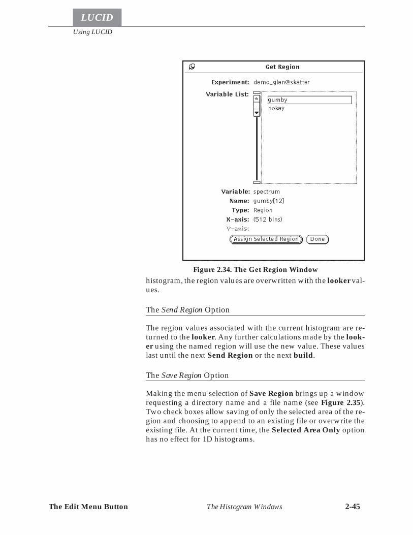
The Edit Menu Button
Using LUCID
LUCID
The Histogram Windows 2-45
histogram, the region values are overwritten with the looker val-ues.
The Send Region Option
The region values associated with the current histogram are re-turned to the looker. Any further calculations made by the look-er using the named region will use the new value. These valueslast until the next Send Region or the next build.
The Save Region Option
Making the menu selection of Save Region brings up a windowrequesting a directory name and a file name (see Figure 2.35).Two check boxes allow saving of only the selected area of the re-gion and choosing to append to an existing file or overwrite theexisting file. At the current time, the Selected Area Only optionhas no effect for 1D histograms.
Figure 2.34. The Get Region Window
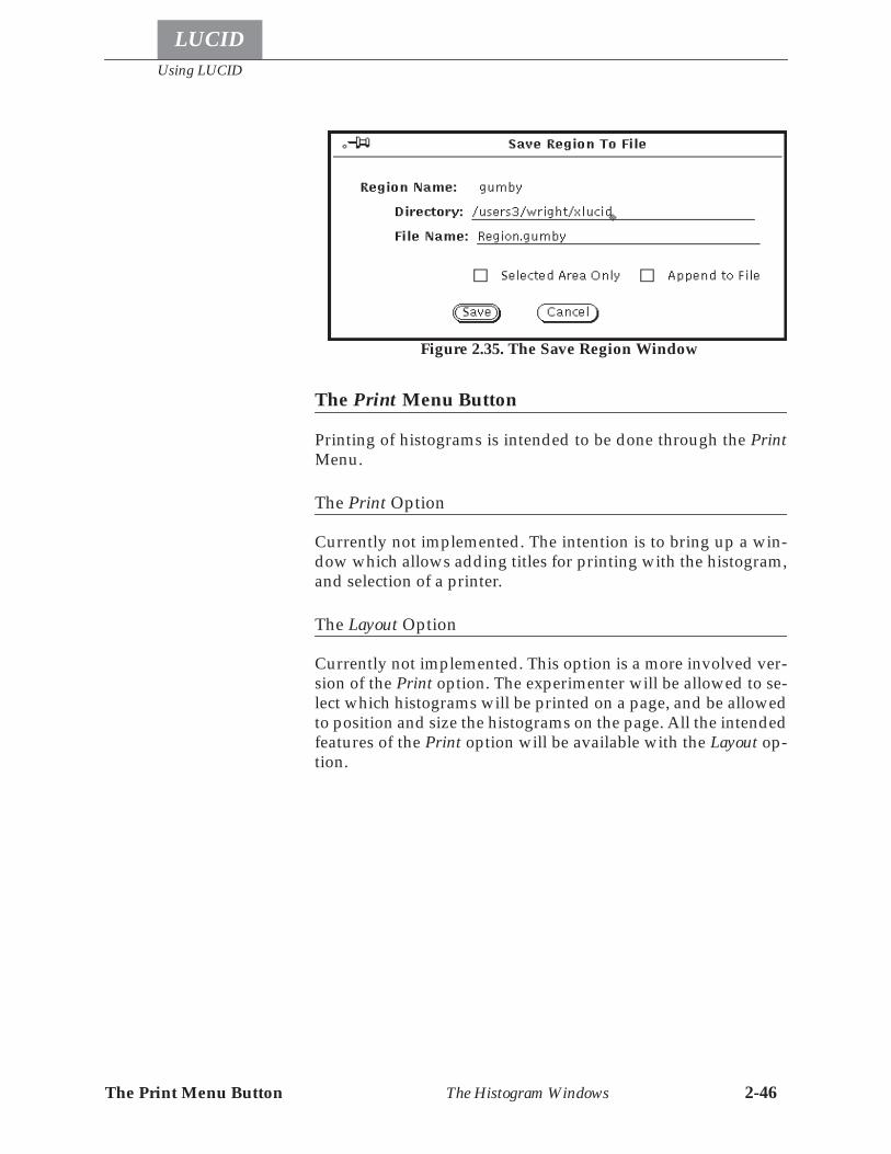
Using LUCID
LUCID
The Print Menu Button The Histogram Windows 2-46
The Print Menu Button
Printing of histograms is intended to be done through the PrintMenu.
The Print Option
Currently not implemented. The intention is to bring up a win-dow which allows adding titles for printing with the histogram,and selection of a printer.
The Layout Option
Currently not implemented. This option is a more involved ver-sion of the Print option. The experimenter will be allowed to se-lect which histograms will be printed on a page, and be allowedto position and size the histograms on the page. All the intendedfeatures of the Print option will be available with the Layout op-tion.
Figure 2.35. The Save Region Window

LUCID
Chapter
CAMAC Requirements Camac Hardware Layout 3-1
3 The Reader
The READER is that part of LUCID which acquires data. It is aprogram that LUCID writes for you, based on a description ofyour experiment. Having the programs written automaticallyfrom an experiment description relieves you of the task of writ-ing all the low-level acquisition routines yourself.The first section in this chapter deals with the way the data ac-quisition hardware must be set up. The remainder of the chapterexplains the details of writing an experiment description thatLUCID will turn into the data acquisition programs.
Camac Hardware Layout
If you’re not concerned with CAMAC at this point, you can skipahead to the next section entitled Making a Reader DescriptionFile on page 3-2.LUCID is a multiprocessor data acquisition system. The hard-ware consists of one or more front-end processors which acquiredata from CAMAC, FASTBUS and VME modules. The front-endprocessors forward the acquired data via an Ethernet link to anacquisition processor. The acquisition processor writes the datato some storage device and makes the data available for furtheranalysis and display.CAMAC modules are connected to the front-end processors by aparallel branch highway. There can be up to eight parallelbranches each with up to seven CAMAC crates. Crate controllersin crates with modules that will be used to generate LAM’s mustbe equipped with a LAM grader card. This card must be wiredto connect the crate LAM lines directly to the parallel branchgraded LAM lines. For example, the LAM line from station 1must drive graded LAM line 1, station 2 must drive graded LAMline 2, and so on till station 23 and graded LAM line 23. GradedLAM line 24 is not used.
CAMAC Requirements
The Reader
LUCID
Using Lams Making a Reader Description File 3-2
Using Lams
LAMS (interrupts) are often used to determine that an event hastaken place. If an event is made up of data from several ADCmodules for example, only one of them should send a LAM.Most CAMAC modules can have LAMs disabled, either by a CA-MAC command or by setting a switch on the module’s side pan-el. If a module’s LAM disable (or enable) is controlled by CAMACcommand, then LUCID will enable and disable the correct mod-ules, based on your description file. If a switch needs setting, youmust do that before trying to acquire data.It is important to remember that modules such as waveform dig-itizers or TDCs may have lengthy conversion times. When usingthem in an experiment, you should have some other modulegenerate the event’s LAM if possible, because the READER can bereading other modules while these “slow” ones are still convert-ing.
Making a Reader Description File
When you ask LUCID to build the programs for your experiment,it needs to know exactly what you want. It gets some of that in-formation from a READER description file, which is a text file thatcan be made with any text editor. LUCID only needs to see thisfile once, at the very beginning of your experiment when it ac-quires the raw data. You won’t have to remake the description inthe future to look at the data off-line.The READER description file should be named appropriately foryour experiment, but must end with ‘.r’ for Reader. You shouldnot use any special symbols such as asterisks or question marksin the filename, but it may contain digits and upper-case letterssuch as in He3.r, or carbon14.r.Remember that LUCID only needs a description of your experi-ment when raw data are being acquired from CAMAC. If youwant to get data from some other place, such as a tape or a diskfile, then you can skip ahead to the next chapter; you don’t needa READER description file to read previously acquired data.
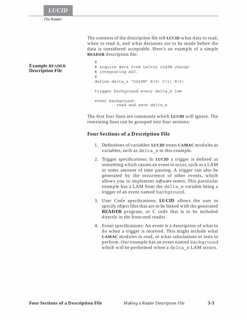
The Reader
LUCID
Four Sections of a Description File Making a Reader Description File 3-3
The contents of the description file tell LUCID what data to read,when to read it, and what decisions are to be made before thedata is considered acceptable. Here’s an example of a simpleREADER description file:
## acquire data from LeCroy 2249W charge# integrating ADC.#define delta_e “2249W” B(0) C(1) N(5)
trigger background every delta_e lam
event background: read and save delta_e
The first four lines are comments which LUCID will ignore. Theremaining lines can be grouped into four sections:
Four Sections of a Description File
1. Definitions of variables: LUCID treats CAMAC modules asvariables, such as delta_e in this example.
2. Trigger specifications: In LUCID a trigger is defined assomething which causes an event to occur, such as a LAMor some amount of time passing. A trigger can also begenerated by the occurrence of other events, whichallows you to implement software events. This particularexample has a LAM from the delta_e variable being atrigger of an event named background.
3. User Code specifications: LUCID allows the user tospecify object files that are to be linked with the generatedREADER program, or C code that is to be includeddirectly in the front-end reader.
4. Event specifications: An event is a description of what todo when a trigger is received. This might include whatCAMAC modules to read, or what calculations or tests toperform. Our example has an event named backgroundwhich will be performed when a delta_e LAM occurs.
Example READERDescription File
The Reader
LUCID
The DEFINE Section CAMAC Variables Making a Reader Description File 3-4
The four sections of the READER description file must be in or-der. The definitions must be first, followed by the triggers, thenthe user code (if any), and then the event section. Each sectionmay contain any number of lines, and the statements within eachof these sections are completely free format. Notice that eachstatement begins with a name appropriate to its section: define,trigger, load or program, or event.LUCID makes no assumptions about columns in the file as FOR-TRAN does, but experience recommends that each line be keptshort so as to be easy to change with a text editor. Related state-ments should be indented (with a TAB character, for instance) bythe same amount. Blank lines are acceptable and encouraged, toallow easy reading by other people. An octothorpe (#) is recog-nized as the start of a comment. LUCID ignores this symbol andall other characters, up to the end of that line. The only exceptionto this is when that symbol appears between quotes as part of astring constant.
The DEFINE Section
LUCID allows you to do computations with your data as it ar-rives, so you can check its validity. Results of these computationscan be saved as part of an event, along with the raw data. LUCIDallows you to define variables, very much like variables in mostprogramming languages. Furthermore, LUCID treats CAMACmodules as variables, allowing easy access and simple manipu-lation.The first section of the READER description file tells LUCID whatvariables you want to use in your experiment. All variables mustbe defined so that LUCID can build correct programs, and tomake sure there are no typing mistakes in your description. LU-CID can also make other checks about the consistency of datafrom CAMAC modules. For example, it will warn you if you at-tempt to assign a twenty-four bit CAMAC module variable into asixteen bit integer variable.CAMAC modules are defined so that variable names can be asso-ciated with them in your description file. The following exampleshows the definition for a Kinetic Systems model 3615 scaler.
define doubles “3615” B(0) C(1) N(10) A(0-2)
Define CAMACVariables
The Reader
LUCID
The DEFINE Section CAMAC Variables Making a Reader Description File 3-5
This particular statement tells LUCID that you have such a scalerin station 10 of CAMAC crate 1 on branch 0. It also tells LUCIDthat you are interested in only the first three inputs, subaddress-es numbered 0 through 2. The module can be referred to with thevariable name doubles, and we will see that it is actually an ar-ray containing three values.LUCID knows details of how to access this module because it hasaccess to a CAMAC database (see Appendix A, The CAMACModule Database). All common modules have entries in thissystem database, so that each experimenter need only specify aminimum amount of information to have the module accessedproperly. In this example, the identifier “3615” was recognizedbecause it is listed in the database, along with a description of themodule being a 100 MHz scaler. Another name for the samemodule could be used, such as “KS3615” or “Kinetic Sys-tems 3615", both of which appear as alternate names in thesystem file. This system module database is simply a text file thathas been set up (and is maintained) by the system administrator.LUCID users are allowed to read through the file, and even maketheir own additions. A user is allowed to supply his own data-base file if he needs to access a module in a non-standard way.LUCID will read the user’s file and then the system database, us-ing the first entry with a matching name. When searching formodule names in the database, LUCID considers only alphanu-meric characters. There is no differentiation between upper andlower case characters. For example, the names LeCroy 2228,LeCroy2228, and lecroy2228 all match the same module,LeCroy 2228 Time to Digital Converter.The format of the module database file is described in detail inAppendix A of this manual. The entries are in alphabetical orderfor easier reading. When creating your own module names andaliases, try and maintain a consistency with the database. E.g.,
4508, LeCroy 45083615, ks3615, ksc3615, Kinetic Systems 3615
The B and C keywords in our example are optional. LUCID as-sumes that the module is in branch 0 crate 1 unless told other-wise. Referring back to the original example:
define delta_e “2249W” N(1)
Although this module is more complicated than the scaler of theprevious example, it’s definition is smaller because all inputs areto be read when it is accessed. The sub-address code is optionaland LUCID assumes all sub-address codes are to be used if youdon’t list any in your definition.
CAMAC Database
The B and C keywords
CAMAC subaddresscodes
The Reader
LUCID
The DEFINE Section Defining Variables Making a Reader Description File 3-6
For some experiments, it may be efficient for certain modules notto interrupt the computer. Rather than waiting for a LAM, LUCIDcan continuously poll a module to determine when data is ready.This is important when you have a module with a slow conver-sion time that is to be read out after a LAM is received from someother module. The details of how you wait for the data will bediscussed under the heading Polling Camac Modules on page3-20, but at this point the concern is timing.It usually isn’t a good idea to just wait forever for a module to be-come ready, so LUCID allows you to specify a timeout period.This tells the READER that if it must wait for the module, then itmust not take longer than a certain amount of time. If it does takelonger, the data is considered bad. A CAMAC module’s timeoutvalue must be given with the definition, as shown in the examplebelow:
define energy “LeCroy 2259” N(10) timeout 10 microseconds
Times up to several minutes may be specified, although only afew microseconds should ever be necessary for most applica-tions. You may actually use the following keywords to specifytimes: microseconds, milliseconds, seconds, min-utes. A default timeout is included in the CAMAC module da-tabase for most “slow” modules.
How to DEFINE Variables
LUCID variables are defined in a way similar to FORTRAN, asshown in this example:
define energy real*4
This statement defines a single precision variable named “ener-gy”. Several variables of the same type may be defined in thesame statement:
define e1,e2,e3 integer*2
Module Timeouts
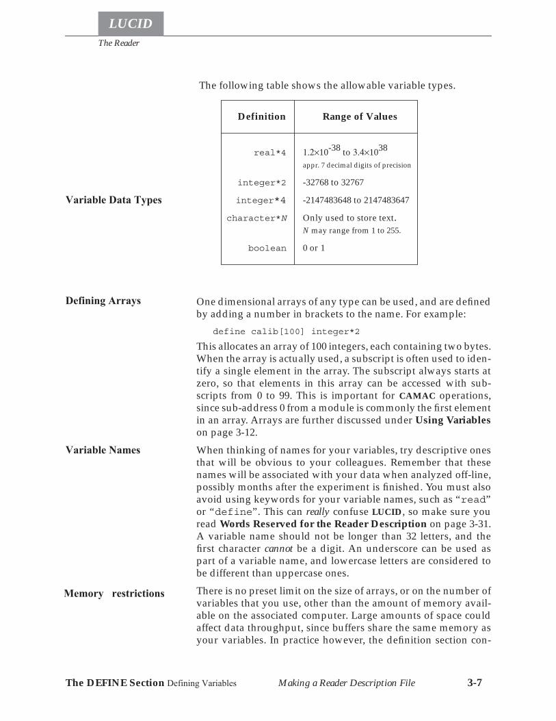
The Reader
LUCID
The DEFINE Section Defining Variables Making a Reader Description File 3-7
The following table shows the allowable variable types.
One dimensional arrays of any type can be used, and are definedby adding a number in brackets to the name. For example:
define calib[100] integer*2
This allocates an array of 100 integers, each containing two bytes.When the array is actually used, a subscript is often used to iden-tify a single element in the array. The subscript always starts atzero, so that elements in this array can be accessed with sub-scripts from 0 to 99. This is important for CAMAC operations,since sub-address 0 from a module is commonly the first elementin an array. Arrays are further discussed under Using Variableson page 3-12.When thinking of names for your variables, try descriptive onesthat will be obvious to your colleagues. Remember that thesenames will be associated with your data when analyzed off-line,possibly months after the experiment is finished. You must alsoavoid using keywords for your variable names, such as “read”or “define”. This can really confuse LUCID, so make sure youread Words Reserved for the Reader Description on page 3-31.A variable name should not be longer than 32 letters, and thefirst character cannot be a digit. An underscore can be used aspart of a variable name, and lowercase letters are considered tobe different than uppercase ones.There is no preset limit on the size of arrays, or on the number ofvariables that you use, other than the amount of memory avail-able on the associated computer. Large amounts of space couldaffect data throughput, since buffers share the same memory asyour variables. In practice however, the definition section con-
Variable Data Types
Definition Range of Values
real*4 1.2×10-38 to 3.4×1038
appr. 7 decimal digits of precision
integer*2 -32768 to 32767
integer*4 -2147483648 to 2147483647
character*N Only used to store text.N may range from 1 to 255.
boolean 0 or 1
Defining Arrays
Variable Names
Memory restrictions
The Reader
LUCID
The TRIGGER Section Trigger Types Making a Reader Description File 3-8
sists of as many definition statements as you care to include.Keep in mind that although an array may be very large, you ar-en’t allowed to save more than approximately 32,000 bytes inany one event. A point to remember is that all LUCID variablesare guaranteed to be zero when the program starts. This doesn’tmean they will be reset to zero before every run, but they will bezero before the first start command is issued.A few sample definitions are listed here:
define energy1 integer*2define energy2 real*4define pi1,pi2,pi3,pion[40] integer*2define time1 “LeCroy 2229” N(10) A(6-11)define counts “lrs4448” N(11)
The TRIGGER Section
Normally, we think of an event as some happening or occurrencewhich causes a result. LUCID defines an event as a collection ofdata items. When data is recorded on tape for example, it is basi-cally a list of thousands of events, one after another. A trigger isdefined as some occurrence which causes the event to be pro-cessed. If the source of the data is a CAMAC module, then a trig-ger is often a CAMAC LAM.Triggers must be described in the second section of the READERdescription file. The section contains statements which associatesome occurrence with the action of acquiring the data. There areseveral types of triggers that LUCID can respond to:
• CAMAC LAMs (interrupts). • CAMAC modules which set a “ready” status bit. This im-
plies polling for a “data ready” state. • Some amount of time passing. • A certain number of valid events occurring. • Executing a trigger statement in an event specification. • A change in LUCID’s state, such as the start or end of a
run. • A request from the experimenter. • Some external source making data available.
The syntax of the trigger definition statement is shown in the fol-lowing example:
trigger electron_arm every delta_e lam or every 3 seconds
Definition Examples
Trigger Types
The Reader
LUCID
The TRIGGER Section Software Triggers Making a Reader Description File 3-9
The trigger statement always starts with the keyword trigger.The next portion tells the READER to perform some action calledan “electron_arm event” when the triggers arrive. Details ofthat electron_arm event would be described in the event sec-tion of the file. This particular example associates two differenttriggers with the event, specifically a LAM from the CAMACmodule named delta_e, and a time interval of 3 seconds. Wheneither of these things occur, the trigger is performed. LUCID al-lows several triggers to cause an event. If both things happen atthe same time, LUCID will see both of them; nothing will be lost,because triggers remain pending until serviced.In many experiments, the user will want to perform some kindof “housekeeping” duties at the end of a run, such as readingscalers or disabling high voltage equipment. LUCID generates atrigger automatically when you give a command to start or stopa run. For instance, it is acceptable to say:
trigger scaler every endrun
There are four such “internal” trigger names, called beginrun,endrun, suspendrun and resumerun. As shown in the exam-ple, they are associated with events in the same way as a CAMACLAM or a time unit would be. These triggers will be issued whena start, stop, suspend, or resume command is given to theLUCID program. When triggering from a start or resume com-mand, LUCID will produce the trigger before doing anythingelse. Correspondingly, a stop or suspend command will causeLUCID to finish whatever it’s doing, and issue those triggers last.Sometimes housekeeping duties are required to be performedbefore a run is finished, possibly after a certain amount of datahas been collected. LUCID allows you to specify that a certainnumber of processed events will act as a trigger. For instance,you could use the following statement:
trigger scaler every 1000 delta_e
This allows you to read the scalers after processing one thousandreal data events, ideally to guard against counters overflowing.Note that the trigger is not really put into effect until after theone-thousandth “delta_e” event has been successfully pro-cessed.An event can trigger another event. See Triggering AnotherEvent on page 3-26 for a description of how this is done.
The Trigger Statement
LUCID State Triggers
Software Triggers
The Reader
LUCID
The TRIGGER Section Software Triggers Making a Reader Description File 3-10
LUCID allows you to attach a command on your terminal to atrigger. This is often used for testing various parts of your equip-ment before the experiment actually starts. For example:
trigger reset every “reset” command
This attaches a trigger to an event called “reset”, which will beperformed whenever you type the command reset to the LUCIDprogram. Any sequence of keystrokes can be used, includingcontrol characters. Notice that the command name must be en-closed in quotes.If the LUCID program is being used with a different interface,such as a mouse on a workstation, then it will install your com-mand on a software button. In that case, you could simply pointthe mouse arrow at the appropriate title and click the mouse but-ton. See Control Buttons on page 2-19 for more information.To enter a control character as part of the triggering command,type a circumflex in front of the character’s symbol. For example,
trigger reset every “^R” command or every highvoltage lam
This will cause the reset event to occur whenever you type acontrol-r to the LUCID1 program, or if the “highvoltage” modulegives a lam. If you really want to have the circumflex (^) as partof a command, you should enter two of them in the command,one after another (^^).The ready status of a module can initiate an event through thewhen module ready trigger. LUCID then checks for a Q responsefrom the module continuously, and the event executes when a Qresponse occurs.Finally, there is the simplest of all triggers. If you enter the key-word constantly as part of the statement, LUCID will triggerthe associated event as often as it can, but allow other triggers totake precedence when they arrive. For example:
trigger tdc_readout constantly
This statement will cause the “tdc_readout” event to be per-formed as fast as the computer will allow. All other triggers list-ed in the file always take priority over this type of trigger, exceptfor other ones being performed constantly.
1. The XLUCID program does not recognize control characters: it only allows commands to be run bybutton selection. For this reason, it makes more sense to have commands with meaningful names rath-er than single key presses.
Keyboard Triggers
Module ReadyTriggers
Continuous Triggers(Polling)
The Reader
LUCID
The USER CODE Section Software Triggers Making a Reader Description File 3-11
Some examples of trigger statements are listed here:trigger good_hit every tdc lamtrigger counting every 2 secondstrigger delta every “test” command or every coincidence lam or every 10 overflow event or every 60 minutestrigger calibrate every minutes
The USER CODE Section
It is common for a non-standard module in an experiment to re-quire some special handling which the READER language cannot easily provide. The user code section has two statementtypes, one of which allows direct inclusion of C code, and thesecond which allows specifying object modules or libraries to beused.C code is included directly with the program keyword; e.g.
program “/home/wright/Lucid/bitswap.c”
This statement causes the named file to be included in the gener-ated frontend program. The C code can declare global variablesand functions, and have access to the variables and definitionscreated from the DEFINE section. Variables and functions de-fined here can only be accessed by user code entries in theEVENT section (see User-written Code on page 3-29)The second type of inclusion is with the load keyword; e.g.
load “/home/wright/Lucid/readercommon.o”load “/home/wright/Lucid/readerlib.a”
Files named with the load statement may have been generatedfrom FORTRAN, ASSEMBLER, or C, or may be a library or ob-ject files so generated. The only restriction on the compiler usedto create the object file is the functions must be C callable, or theglobal variables must be C accessible. Object files or librariesbuilt in this way do not have direct access to the variables or def-initions created from the DEFINE section1; instead, calling rou-tines must pass the variables (or their addresses) to the routinesin the object files.
1. The source files for loaded object files and libraries could include frontend.buildname.h file in theexperiment directory to gain access to the DEFINES and structure definitions. The user must find thepath to this file (see The LUCID Experiment Directory on page 6-4). The user’s source files arenot automatically recompiled when a change in the reader file causes a change in the .h file.
Trigger Examples
The Reader
LUCID
The EVENT Section Making a Reader Description File 3-12
A word of caution is necessary at this point. LUCID will recordthe reader description file to the output device, but does not at-tempt to record any files referenced by a program or load state-ment. This means it is no longer possible to re-create exactly theenvironment an experiment had when it was run. Code includedin the reader in this manner should be printed and included inthe experiment log book, and all changes to the code should like-wise be documented.
The EVENT Section
The event section of the READER description file is usually thelargest, because it tells LUCID what to do after receiving a trigger.The section consists of one or more event specifications, one afteranother in the file. Each specification may contain many state-ments, but the first statement is an event name, similar to a sub-routine name in a programming language. For example, thestatement
event electron:
associates all subsequent statements (up to the next event speci-fication) with the event name electron. Notice that the firstword is event, being similar to the first word of the define andtrigger sections.LUCID makes sure that every event name that you specify is trig-gered by something. If LUCID finds an event without a trigger, itwill warn you that the event will never be performed.The rest of the statements in the event specification are similar tothe statements in most programming languages, allowing you toaccess any variables (including CAMAC variables) that were de-fined in the first section of your file, and perform tests or somearithmetic on the associated data.
Using Variables
The acceptable range of values for numeric arguments was listedunder How to DEFINE Variables on page 3-6. A variable de-fined as character can contain any valid ASCII character be-tween 40 octal and 176 octal (i.e. between the space character andthe tilde (~) character), the return and newline characters, and thetab character. The null byte is reserved for internal use, andmarks the premature end of a string of characters in a larger vari-able. Boolean variables are numeric variables which may onlycontain a one or zero. A value of one denotes a true state, andzero a false one.
The Reader
LUCID
The EVENT Section Using Variables Making a Reader Description File 3-13
LUCID understands integer constants in binary, octal or hexadec-imal (base two, eight, and sixteen, respectively). To specify a con-stant in base eight for example, you should make the first digit a“0”, as in:
0351
Similarly,0b11101001 and 0xe9
refer to the same number (233) in base two and hexadecimal.Base 16 numbers can use either upper or lower case letters “A”through “F”.Statements in an event specification can access variables, includ-ing CAMAC modules and arrays. Character variables are usedinfrequently, usually to record an operator’s name or the nameof an experiment within the data stream. Recall that all variablesmust be defined in the define section of the description file.When elements of an array are accessed, an index must be givenbetween brackets following the array name, such as “phi[3]”.Remember that all arrays are indexed starting at zero, so that thisparticular example is referring to the fourth element of the arraycalled “phi”. An index of a subscript may be any arbitrary ex-pression that evaluates to an integer.Arrays may be named without subscripts, allowing operationsto be carried out on every element. For instance, if we assume thatthe array “theta” contains fifty integers, the statement
theta = 100
will set every element of the array “theta” to be one hundred.Because most CAMAC modules have several inputs, CAMACvariables represent arrays having subscripts which correspondto their sub-address (A) codes. All CAMAC variables are identicalto arrays in that they are indexed starting at zero. For example,let’s assume that the definition of a CAMAC variable “adc” indi-cates that only sub-address codes five through eleven of the CA-MAC module are to be accessed.
define adc “lrs2259B” N(4) A(5-11)
Constants
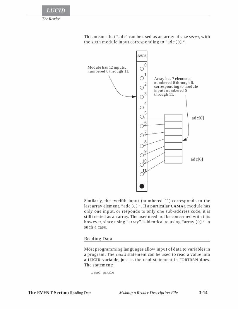
The Reader
LUCID
The EVENT Section Reading Data Making a Reader Description File 3-14
This means that “adc” can be used as an array of size seven, withthe sixth module input corresponding to “adc[0]”.
Similarly, the twelfth input (numbered 11) corresponds to thelast array element, “adc[6]”. If a particular CAMAC module hasonly one input, or responds to only one sub-address code, it isstill treated as an array. The user need not be concerned with thishowever, since using “array” is identical to using “array[0]” insuch a case.
Reading Data
Most programming languages allow input of data to variables ina program. The read statement can be used to read a value intoa LUCID variable, just as the read statement in FORTRAN does.The statement:
read angle
2259B
Module has 12 inputs,numbered 0 through 11.
Array has 7 elements,numbered 0 through 6,corresponding to moduleinputs numbered 5through 11.
1
2
3
4
5
6
7
9
10
0
11
8
adc[0]
adc[6]
The Reader
LUCID
The EVENT Section Reading Data Making a Reader Description File 3-15
will cause the READER to print a message on the user’s terminal,in the form
Enter angle:
The READER will then stop and wait for the user to enter a valuethat is consistent with the definition of angle. We are assumingthat “angle” is defined as a true variable, and not a CAMAC vari-able or an array. When prompting for input, the READER simplyprints the word Enter, followed by the name of the variable. Ifyou would like to give the operator more information aboutwhat’s expected for input, you can specify a message in the readstatement, after the variable name. For example, the statement:
read angle “the spectrometer angle, 20-60 degrees”
would displayEnter angle (the spectrometer angle, 20-60 degrees):
to the operator.If the variable is actually an array element, then the defaultprompt would indicate that fact to the user. For instance, thestatement
read adjust[0]
would cause the READER to prompt withEnter adjust[0]:
If the name of an array is given without a subscript, the READERwill prompt for each element’s value in turn, until each one hasbeen read.
Enter adjust[0]:Enter adjust[1]:Enter adjust[2]:
•••
Although LUCID allows you to enter certain values interactivelyas your experiment proceeds, this isn’t always convenient ifyou’re not sure when they will happen, or if an inexperiencedcolleague is filling in for you. LUCID offers two flexible optionsfor reading values into variables.The first option allows you to read values from a file. The state-ment:
read adjust from “/home/wright/adjustments”
Reading Array Data
Reading from a File
The Reader
LUCID
The EVENT Section Reading Data Making a Reader Description File 3-16
will cause the READER to get the data from the named file, ratherthan from the user’s terminal. This allows large arrays to be readdirectly from a file while an experiment is running. The namedfile must contain a filesystem pathname, and refers to a file on thecomputer on which the experiment is running (as specified aspart of the experiment name, not necessarily the computer theLUCID command was run on). Naturally, you must have per-mission to read that particular file.LUCID will use the first value in the file for the variable, so therest of the file could contain anything. If you’re reading an entirearray, each value should be separated by blank spaces, tab char-acters, or appear on different lines. As with single variable files,LUCID will ignore the rest of the file after it has retrieved enoughinformation to fill the array.Notice that this option contains the keyword from, which tellsLUCID that the name in quotes refers to a file, rather than a promptfor interactive reading. Only one array or variable can be read froma file.The second option allows you to use the output from some pro-gram as the value to use for the variable. For instance, the state-ment:
read adjust from program “/home/wright/bin/getadjustments”
when executed, tells LUCID to start the “/home/wright/bin/getad-justments” program running on the computer which is runningthe READER, LOOKER and WRITER. LUCID takes the first pieceof information output from the program, and places it in thenamed variable. If the variable is an array name, then LUCID willtry and get the correct number of values from the output, and as-sign each one to successive array elements. The program willoutput the values separated from one another by blank spaces ortabs, or place each value on a separate line.As with filenames, the program name must refer to a completefilesystem pathname, and you must have permission to run thatprogram. Within quotes, you specify the program name just asyou would if you were sitting at a terminal. For example, a col-league might have a program which can read settings of variousmechanical components of a detector. At your terminal, youmight normally type
/home/wilson/getvalue B302
File Format
Reading from aprogram’s output
Program Options
The Reader
LUCID
The EVENT Section Reading Data Making a Reader Description File 3-17
to find the setting of some component named B302. From withinyour LUCID program, you can type
read energy fromprogram “/home/wilson/getvalue B302”
The program can be any executable program, including a com-mand script. Furthermore, you can specify input redirection anduse pipes between the quotes to start a pipeline of several pro-grams, just as you would from a terminal. The programs are al-lowed to access other computers, or do anything that anordinary program can do, but it must produce output in the waymentioned above. Also, when LUCID runs the program(s), theyaren’t allowed to have any input from the user. Parameters canonly be passed to program(s) on the command line which startsthem.So far, the read statement sounds like a simple but reasonablestatement for a programming language to use. However, whenwe consider that LUCID is meant to acquire experimental data athigh rates, it seems out of place. Actually, the intended purposeis to allow certain parameters to be input at the beginning of arun, for example. This might include data which was not easilyaccessible on line, such as a spectrometer angle, or the mixture ofgas in a wire chamber. Remember that the READER simply stopsand waits for input when it encounters this statement, essential-ly stopping the experiment. If a user is not running the LUCIDcommand when input is needed, the READER will simply waituntil one exists before prompting for input.Now, we’ll consider something a bit more useful. If the variableused in the read statement is a CAMAC variable, then the corre-sponding CAMAC module will be read. If you attempt to supplya prompt, such as the one in the previous examples, LUCID willgive you an error when you build the software. Recall that CA-MAC variables are considered to be arrays, because they maycorrespond to modules with several inputs. Let’s refer back toour example of an adc module which was defined as using in-puts five through eleven; the following statement could be usedto acquire that data:
read adc
As mentioned in the last section, referencing an array withoutusing a subscript causes the entire array to be accessed. Theoret-ically, one could replace this example with seven read state-ments, each using “adc” with a different subscript, but achievingthe same goal. Such a technique would work, but would bemuch slower than reading the entire array in one statement.
When to use read
Reading CAMACVariables
The Reader
LUCID
The EVENT Section Saving Data Making a Reader Description File 3-18
The READER determines how to read the modules by checkingthe system CAMAC database, as described in Appendix A.
Saving Data
Probably the second most important feature of LUCID after read-ing the data is saving it someplace. We’ve mentioned that theWRITER will actually record the data, but the READER must de-termine which variables should be saved. The save statementtells the READER to save a variable for the rest of the system touse. Remember that reading a variable does not mean that it willbe saved.The save statement is usually combined with the read state-ment:
read and save adc
This method is the most common way of acquiring data, but itplaces a restriction on the rest of your event. Specifically, if LU-CID finds a statement of this form, where the variable is beingread and saved on the same line, it will move the data directlyfrom CAMAC to the data stream. This is the fastest way of acquir-ing data, but it means that the data won’t be available to the restof your event statements, or even within this event statement.It is quite acceptable to use two separate statements:
read adcsave adc
This is less efficient than the previous example, but it tells LUCIDto save the data for future computations by the READER.As one might expect, using the save statement on an array withno subscript will save the entire array. You should also be awareof a restriction placed on the save statement when the if state-ment is used. Specifically, you aren’t allowed to save data withinan if statement.The structure of an event “record” is determined by the order inwhich variables are saved in the event specification. For thoseusers wanting to write their own software, the build commandputs a definition of the event record into a LUCID file. A C “in-clude” file containing the structures describing the event data isalso produced. There are also subroutines available to read theevent record, so it is unnecessary to manually write code whichknows the actual event record layout. These features are furtherdescribed in Chapter 7.
A special form of the save command is:save data
NOTE:
SAVE Restriction
Format of Event Data
The Reader
LUCID
The EVENT Section Other CAMAC Operations Making a Reader Description File 3-19
This statement causes any data buffered by the front-end com-puter to be transmitted as soon as possible. For an experimentwith a low acquisition rate, this statement could be placed in anevent triggered every few seconds, or possibly in an event trig-gered by a user command.Alternatively, the special save command can be entered assave data and waitAs with the save data command, this immediately causes thedata buffer to be transmitted to the user’s LUCID session. How-ever, acquisition will not continue until the LUCID session hasprocessed this data! The effect is that none of the different soft-ware sections of the experiment get too far ahead of any othersection, and responsiveness to user commands (including “stop”and “pause”) is maintained. Because this statement can createlarge dead times, depending on the amount of processing occur-ing in the LUCID LOOKER, it should not be used for produc-tion runs.
Other CAMAC Operations
To process some events, other CAMAC operations must be per-formed after the data is read. This could include clearing an in-put, resetting a LAM, or adjusting other module parameters.It is often important to clear a CAMAC module before proceedingwith an event. The following statement can be used:
clear adc
In most cases, this issues a CAMAC F(9) command, which usuallyclears the lam status bit as well as clearing the module. The sys-tem CAMAC database is used to determine the correct functioncode.Many CAMAC applications require that a module be cleared af-ter it is read. Most modules have an single read-and-clear opera-tion, in addition to a simple read function. By using thestatement
read and clear adc
the READER will perform the correct CAMAC function (usuallyan F(2) command). The READER will use a different functioncode simply because the read keyword appears. The clearstatement has a different meaning when used independently.Using clear on a normal variable (i.e. one that isn’t a CAMACvariable) will simply set the variable (or entire array) to zero ifdefined numeric, null if defined as a character, or false if de-fined as a boolean.
Clearing CAMACModules
Read and ClearOperation
The Reader
LUCID
The EVENT Section Other CAMAC Operations Making a Reader Description File 3-20
The rule to remember is that when read and clear commands ap-pear in the same statement, and if the module supports the read-and-clear operation, the module is issued a single CAMAC com-mand containing (usually) F(2). If the commands are in separatestatements, or the module has no single read-and-clear opera-tion, then two separate CAMAC commands will be issued.The clear command can be combined with the earlier read andsave command, giving
read, save and clear adc
This is particularly efficient method for many modules.
Polling Camac Modules
The term “polling a module” refers to the action of repeatedly ac-cessing a module until it says that data is ready.It is essentialwhen reading from modules that have a lengthy conversiontime, but do not issue a lam when finished. Note that a lamsource signifies a unique trigger, and LUCID can’t perform a por-tion of an event when a trigger arrives. Therefore, if several mod-ules are to be read, only one of them can issue a lam. Asmentioned on page 3-6, modules with lengthy conversion timesshould not be the ones to issue the LAM, and they should be readlater in the event, giving them time to finish. In such cases, poll-ing the module is required.The keyword wait can be used to poll a module by giving it thename of an associated CAMAC variable. For example:
wait adc
will cause the reader to continuously send a CAMAC commandwhich tests for data being ready. Most modules respond to theCAMAC F(8) command by issuing an appropriate Q response. AQ response of true (a one), indicates data is ready. The CAMACfunction code that will be used is looked up in the system CA-MAC database for the module, and LUCID will warn you if a par-ticular module has no polling mechanism.Because it is possible the wait command will timeout, the qre-sponse variable should be tested after a wait statement.
wait adcif (qresponse == 0) then # Adc not ready due to timeout. # Reject this event. rejectendif
Read, Save and ClearOperation
The wait command
The Reader
LUCID
The EVENT Section Compressing Array Data Making a Reader Description File 3-21
As in previous examples, the wait keyword can be used withcertain other keywords. The most common example is:
wait, read, clear and save adc
Each such keyword can be separated from the next by a commaor the and keyword for readability. The wait command has noeffect on non-CAMAC variables, and LUCID will warn about suchusage.
CAMAC Q Response
The wait command can be very useful for certain modules, butcould give incorrect data in other cases; the timeout period thatwas specified for a module may have expired, and the data thatwas acquired could be meaningless1. To let you check for thiscondition, LUCID provides a boolean variable, called qre-sponse. It does not have to be defined like other variables, sinceLUCID defines it for you. It can be used wherever a normalboolean variable could appear. Is best suited to the if com-mand, described under Making Decisions about the Data onpage 3-25.The qresponse variable will contain a one (true) value if thelast CAMAC operation returned a Q response, and it will be zerowhen there was no Q response. You should not assign some val-ue to the qresponse variable as you would other variables as itis considered “read only”.
Compressing Array Data
In many experiments, a sparse matrix of data may be acquired.For instance, a wire chamber could have hundreds of TDC chan-nels, most of which will contain irrelevant data when a triggerarrives. When a computer goes to read and save the data, mostof it is unimportant.LUCID allows you to compress an array by specifying what youconsider to be unimportant. The compression actually refers todiscarding all unimportant data, and adding an index for eachgood value. For instance, if an array of one hundred TDC valuescontained “unimportant” data except for the last two elements,the compressed array would contain four elements: the numberninety-eight and the second last TDC value, followed by thenumber ninety-nine and the last TDC value.
1. The definition of a timeout delay is discussed on page 3-6.
The Reader
LUCID
The EVENT Section Compressing Array Data Making a Reader Description File 3-22
Any CAMAC variable can be compressed. In some cases, it couldbe quite inefficient to do so, as the saved data contains both thesaved values and the saved indices. For instance, if less than halfof the inputs to a module have “unimportant” values, compress-ing the data would result in an array larger than the original!To use this feature, simply use the compress keyword in thesame way as read or save. For example, the following state-ment is valid, assuming that “timing” is defined as a CAMACvariable:
read, compress and save timing
In this default case, LUCID assumes that zero values are unim-portant, and all non-zero values are saved. The compress fea-ture only makes sense when used with the read and savecommand. The compress keyword will be ignored if read andsave is not specified on the same line.It is often important to have some range of unimportant valuesfor compression, such as the case of a TDC module operating incommon-start mode. In this instance, all full-scale values wouldbe unimportant. At this point, we can think of the compressstatement as a software discriminator. The following exampleshows how this can be done:
read, compress and save timing (discard 200-255)
This is similar to the previous example, except any values in therange of two hundred to two fifty-five inclusive are removedwhen the compression is done. The discard keyword can ac-cept a list of values as well. For example:
read, compress and save timing (discard 0-100,180,200-255)
This statement might be useful when correcting for hardwareproblems, such as a bad wire in a wire chamber (i.e. when youwant to ignore a particular channel).A second type of compression is performed for Q-Stop modules.Again, the READER is saving a variable number of entries forthe module. However, only the values are saved. The array’s in-dexing is assumed to go from 0 to the number of values saved.As in previous examples, the compress statement can be usedwith read, clear, wait, and so forth. Several variables may bespecified for any of these operations.
read and save adc, delta_e and e_prime
The compressStatement
More GeneralSoftware Discrimination
Q-Stop Compression
Several Variablesat Once
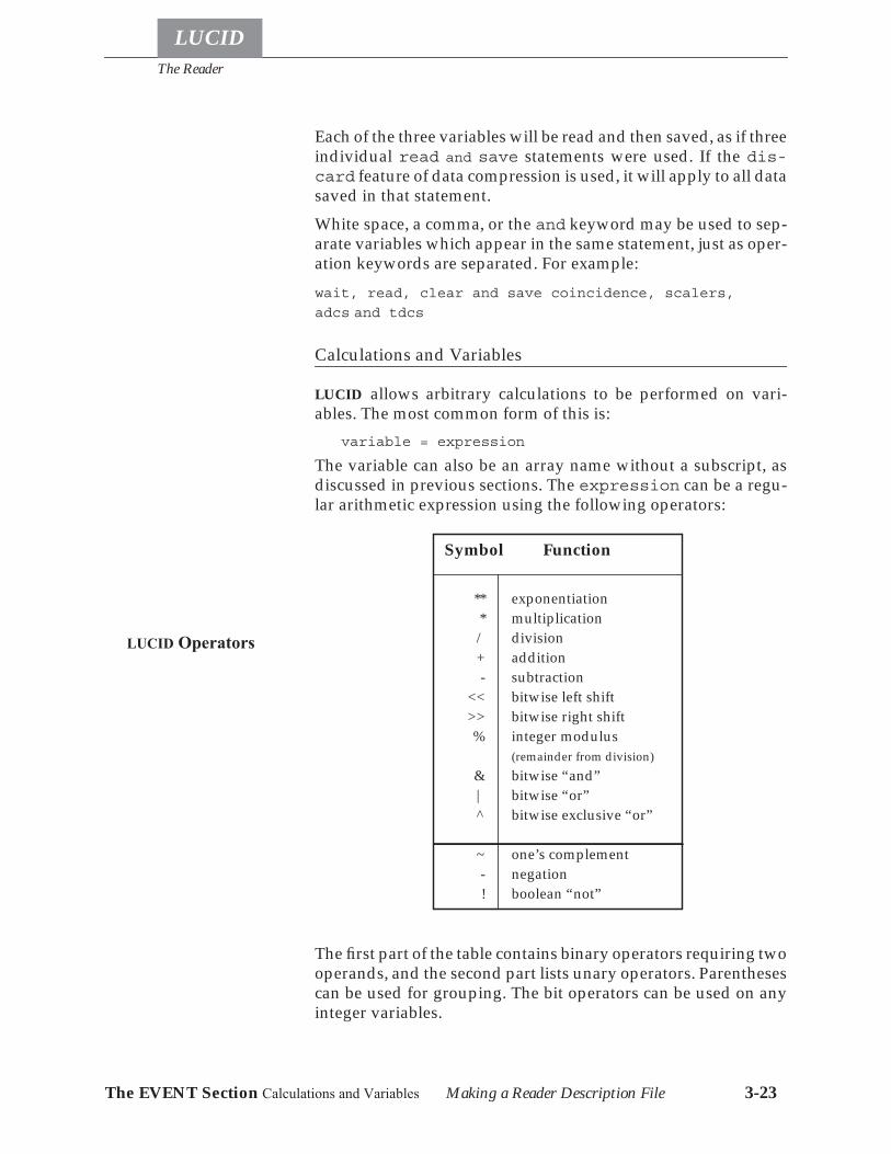
The Reader
LUCID
The EVENT Section Calculations and Variables Making a Reader Description File 3-23
Each of the three variables will be read and then saved, as if threeindividual read and save statements were used. If the dis-card feature of data compression is used, it will apply to all datasaved in that statement.White space, a comma, or the and keyword may be used to sep-arate variables which appear in the same statement, just as oper-ation keywords are separated. For example:wait, read, clear and save coincidence, scalers,
adcs and tdcs
Calculations and Variables
LUCID allows arbitrary calculations to be performed on vari-ables. The most common form of this is:
variable = expression
The variable can also be an array name without a subscript, asdiscussed in previous sections. The expression can be a regu-lar arithmetic expression using the following operators:
The first part of the table contains binary operators requiring twooperands, and the second part lists unary operators. Parenthesescan be used for grouping. The bit operators can be used on anyinteger variables.
LUCID Operators
Symbol Function
** exponentiation* multiplication/ division+ addition- subtraction
<< bitwise left shift>> bitwise right shift% integer modulus
(remainder from division)& bitwise “and”| bitwise “or”^ bitwise exclusive “or”
~ one’s complement- negation! boolean “not”
The Reader
LUCID
The EVENT Section Printing Messages Making a Reader Description File 3-24
An expression cannot contain a subscript-less array referenceunless it is used in an assignment to an array. For instance, it islegal to use an assignment like:
corrections = corrections * 4
where ‘corrections’ is previously defined as some kind of nu-meric array. However, it would be incorrect to use
path[7] = corrections * 4
where ‘corrections’ is the same numeric array. In this exam-ple, note that ‘path’ is an array containing at least eight elements(indexed 0 through 7), so the entire ‘corrections’ array can’tfit into a single element of ‘path’. A further restriction is that thearray on the left side of the assignment must be the same size asan array on the right side. If there is no array mentioned on theright side of an assignment, then each element of the left-hand-side array will be set to the same value.CAMAC variables are not accessible after a read and save oper-ation. If such data are to be used in calculations, the read and
save operations must appear in different statements.
Printing Messages During Event Processing
It is necessary to display messages, usually during an initial set-up period, and occasionally when an unusual type of event is en-countered. Because printing can slow event handlingsignificantly, message printing should be limited to special cir-cumstances.LUCID allows you to print messages with the print statement.Variables and character strings may be printed in any combina-tion, and are separated by commas, as shown in this example:
print “Signal from scintillator”, scin, “,value was”, tdc[scin]
In this example, the variable “scin” contains some input registervalue, and “tdc” is an array of time values from a CAMAC mod-ule. The resulting message might say:
Signal from scintillator 3, value was 511
The message is sent to every screen which is currently using theLUCID command, and will be displayed in their message areas.If there are no LUCID programs running, the messages are placedin a log file. As mentioned, the print statement is not meant tobe used when common events are encountered, because it can re-
Using ArraysWithout Subscripts
The Reader
LUCID
The EVENT Section Making Decisions about Making a Reader Description File 3-25
ally slow down the data acquisition. Printing can take up a lot ofcomputer time, and even worse, a lot of disk space if log files arebeing used. On the other hand, it can be very handy to knowwhen an error occurs during the experiment, or when some in-teresting but infrequent event is found.A variation of the print statement exists to help specifically dur-ing setup or test periods. The display statement has exactly thesame form as the print statement, but it will print the name ofeach variable given, followed by a colon (:), a space and the vari-able’s value. Character strings are displayed in the same way asthe print statement prints them.
Making Decisions about the Data
It is important to perform tests on the data when processing anevent. This could include checking for a certain bit pattern in acoincidence register, or checking the result of a calculation. Thisis done with an if-then-else statement, much as is used in otherlanguages.The following example could be used to check the value of an in-put or coincidence register. The variable coincidence has beenread from a CAMAC module which has three input signals eachwhich is associated with a different event type. There will be onebit in the register corresponding to each event, and the electron-ics doesn’t allow more than one bit to be set at one time:if ( coincidence == 0b001) then trigger calibrateelif ( coincidence == 0b010) then trigger hadronelif ( coincidence == 0b100) then trigger electronelse bad_coincidence = bad_coincidence + 1endifOther statements are introduced in this example. The triggerstatement is a software trigger of the named event, allowing dif-ferent event generation from one initial trigger type.

The Reader
LUCID
The EVENT Section Rejecting an Event Making a Reader Description File 3-26
Triggering Another Event
Some event triggers may not provide sufficient information forthe READER to trigger the desired event type directly. In thiscircumstance, a conditional trigger can be made which causes an-other event to be triggered at the end of the current event, even ifthe current event is rejected! It is even possible to trigger multipleevents to occur after the current event; the events occur in the or-der they are listed in the current event. A conditional trigger ap-pears as:
if ( coincidence == 1) then trigger eventnameendif
Rejecting an Event
After making certain tests, you might determine that some datais in error, or unsuitable for what you wanted to do. In such acase, you can use the reject statement to throw away theevent. When the READER sees the reject statement, it simplystops what it was doing (it backtracks over anything that youmight have saved to that point), and goes back to waiting for atrigger.There is no indication in the event stream that a rejected eventwas encountered.The reject statement is very useful in conjunction with theqresponse variable within an if-then-else statement. You canthen reject an event if a module doesn’t come ready in time.After a reject, any conditionally-triggered events are triggered.Note, however, that events that are to be software triggered(i.e. every N other_event, see page 3-9) will never occurafter a reject.
Writing to Camac Modules
LUCID allows writing to CAMAC modules. This might not seema common thing for a data acquisition system to do, but it provesvery useful in a variety of situations. For example, you couldload an entire programmable logic unit when the experiment isstarted, or when a power supply overcurrent trigger arrives, youcould write a zero value into its controller.You can use the write statement, as shown in the following ex-ample.
write 100 into dac
The Reader
LUCID
The EVENT Section Loading Data into a CA- Making a Reader Description File 3-27
This simply puts the named value into the module named dac,using the default subaddress and function codes for that CAMACmodule, as defined in the CAMAC database. To write largeramounts of data, you could use an array name. For instance, toload an entire file into a programmable logic unit, you could usethe following event statements:
read pludata from “/home/norum/plu.datafile”write pludata into plu
This is inefficient use of computer memory when the pludataarray is only used once in the entire program, taking valuablespace away from data areas. An alternative to this solution isfound with the load statement.
Loading Data into a CAMAC Module
The write statement is useful for loading values into CAMACmodules, but is inconvenient for loading large amounts of data.To handle such cases, LUCID provides a load statement, whichtransfers data from a file directly into a module. For example, thefollowing statement would perform exactly the same function asthe last example in the previous section:
load plu from “/home/norum/plu.datafile”
This is an efficient way of getting values into a module, and itdoesn’t waste any valuable data space.In many cases, an experimenter might load a waveform genera-tor, or a programmable logic unit with numbers produced by aprogram. LUCID allows you to load the output directly into themodule, without making an intermediate file. For example:
load wavegen from program “/home/pywell/bin/makewave”
This is identical to the read from program statement previ-ously discussed. Keep in mind that the exact contents of the fileare loaded into the module; no conversions are done, so thatmodules requiring binary information must be loaded from bi-nary files. It’s also a good idea to check the CAMAC module da-tabase for the number of bits that the module needs for a validtransfer, either sixteen or thirty-two. Your data file (or programoutput) must contain the exact image of what is to be loaded intothe module.
The Reader
LUCID
The EVENT Section Specialized Camac Access Making a Reader Description File 3-28
Specialized Camac Access
LUCID allows you to specify arbitrary CAMAC commands. Forexample:
define controls “sal controller” B(0) C(10) N(1)...
camac controls A(0-11) F(16) data cdat
Here, it is assumed that cdat is an integer variable. In this exam-ple, the CAMAC operation is a write command, and cdat con-tains the data to write out. Similarly in a read command, theREADER will put the data that was read into the named variable.LUCID knows whether you are reading or writing data by check-ing the value of the function code. If the code specifies a controlfunction, then you can’t have the data keyword or a variablename associated with the statement. Although the data variableis optional, its presence depends upon the type of function codeused. If writing, the expression following the data keyword mayalso be a constant value.The subaddress may contain a range of a-codes, in which casethe READER will repeat the function code with each one. Both thefunction codes and the subaddress code(s) must be integers, asopposed to variables.You can also specify a branch, crate and station as in
camac B(0) C(10) N(1) A(0-11) F(16) data cdat
A missing branch specification is taken to be 0, and a missingcrate specification is taken to be 1. Use of this form of the camac
command is discouraged as it is harder to track down andchange the statements when a module is moved.
Camac Crate Operations
Certain CAMAC modules allow you to stop taking data momen-tarily, by using a signal on the CAMAC dataway. The inhibit (I)signal is passed to every station in a CAMAC crate, and is normal-ly in an off state. Some modules will suspend their actions whenthis signal becomes true, and restart when the signal becomesfalse again.LUCID allows you to set or clear this inhibit line from your READ-ER description file. Before using it, you should carefully checkthe hardware manuals for every module within the crate. Somemodules react differently to the inhibit signal, which is sent toevery station.
The Reader
LUCID
The EVENT Section User-written Code Making a Reader Description File 3-29
To set the inhibit line, use the following command:dataway inhibit
If the branch or crate are not specified, the branch is assumed tobe 0, and the crate is assumed to be 1. A more general form of thecommand allows the inhibit signal to be set in different crates:
dataway C(4) inhibit
Specifying crate 0 gets the entire branch at once.Similarly, to clear the inhibit signal and resume module opera-tion, use:
dataway uninhibit
In addition to inhibit and uninhibit, the dataway clear and dat-
away initialize operations are also permitted.
User-written Code
The situation can arise where the READER description languageis inadequate for a particular job. Rather than giving the READ-ER a full-blown general purpose programming language, itmakes more sense to allow access to existing general purposelanguages. The program statement does just that by allowinguser C code to be included at the current point in the event.
define data average compress inputs program “/home/wright/Lucid/reader_calc.c”
The above example tells the reader that the C code in the file “/home/wright/Lucid/reader_calc.c” will place the values of av-erage and inputs in the event record, the latter as a compressedarray. The variables average and inputs must have been de-fined earlier in the READER.There are cases where it is more convenient to include the C codedirectly in the reader rather than in a separate file. This is donesimply by the sequence
program { /* divide average by 2 */ dp->Vaverage /= 2;}
The Reader
LUCID
The EVENT Section Stopping or Suspending an Making a Reader Description File 3-30
To make coding easier, the following definitions and declara-tions are established by the READER:
variable names are Vname (e.g., Vaverage above)variables in the event record are dp->Vname (e.g.,dp->Vaverage)each CAMAC module defined has the C definesCmodule_branch, Cmodule_crate, Cmodule_station,Cmodule_lowaddress, Cmodule_highaddress (e.g.,Cdoubles_branch)
Saving compressed variables takes a special effort. The localvariable cmpvar_offset contains the offset in bytes from the startof the event record (dp) where compressed data can be recorded.At completion of the user code, cmpvar_offset must point to thefirst byte after the end of the saved compressed data that is on aLUCIDALIGN_RECORD boundary. The event-record variable(dp->Vaverage in the above example) is not an array, but rathera structure of type Lucidcompressoffset.The lco_begin fieldmust point to the original cmpvar_offset value, and the lco_endfield must point to the first byte past the end of the compresseddata.Any subroutines that were included in the User-defined Codesection can be accessed only through a program statement.
Stopping or Suspending an Experiment
An experimental run is usually stopped by a command from theuser at a computer terminal. He might decide that there isenough of a data sample to stop then start a new run, or mightwant to temporarily suspend the run for some reason. LUCID al-lows a run to be stopped or suspended from inside an event. Forexample, the following event statement will cause the current ex-perimental run to stop after this event is processed.
endrun
No further triggers will be handled, and no other events per-formed. Similarly, the following statement will cause the experi-ment to be suspended:
suspendrun
These statements allow an experimental run to consist of a pre-cise number of events, or to contain data acquired over an exacttime period; For instance, you could specify that a special eventis to be triggered every 60 minutes. This special event could con-tain a single endrun statement.
The Reader
LUCID
The EVENT Section Words Reserved for the Making a Reader Description File 3-31
Both statements will produce results identical to the correspond-ing commands from the LUCID program. In any case, a user mustmanually restart or resume the experiment by issuing the appro-priate commands from the terminal.
Words Reserved for the Reader Description
LUCID will understand the following words as keywords whenchecking your READER description file. It will complain atlength, probably cryptically, when you try and use any of themas variable names. LUCID considers upper and lower case char-acters to be different, so that n is not a keyword (and can be a val-id, albeit confusing, variable) but defining N as a variable wouldcause a build-time error message.A def loadB define microsecondsC discard millisecondsF display minutesN elif notregionall else orand endgroup previousascii endif printbeginrun endloop programbin endrepeat readbinary endrun readybins event realbinsize events rebinbits every regionbool first rejectboolean from repeatby group resumeruncall hist savecamac histogram secondschar if somecharacter incr suspendrunclear increment thencommand inhibit timeoutcompress initialize tocompressed int triggerconstantly integer uninhibitcontains integrate usingdata into waitdataway label whendecr lam writedecrement last

The Reader
LUCID
The EVENT Section Words Reserved for the Making a Reader Description File 3-32
LUCID
4-1
Chapter
4 The Looker
The LOOKER is the part of LUCID which lets you analyze exper-imental data. It is a program which LUCID writes for you, basedon a description of what you want to do. It will analyze data on-line or off-line, depending only on where the READER is gettingthe data.You might think of the LOOKER as a program that lets you lookat your data. In fact, it doesn’t produce any graphs or pictures atall. It only interprets and arranges the data so that other pro-grams can produce displays. It is called the LOOKER because itlooks at your data, not because it lets you look at it.The LUCID program itself displays the information as the LOOK-ER is doing its work. This implies that the LOOKER need not beconcerned with the type of display screen you’re using, the typeof graphs you want displayed, or even the kind of computer youhave. Another program can be used to draw objects to make upa picture, and do the work of drawing scatter plots or contourplots. You should read Chapter 2 for more information on theLUCID command, and the different ways in which it lets you in-teract with your data.
How the LOOKER Works
The LOOKER extracts data from the LUCID data stream after theREADER acquires and saves it. The original source of “raw” datacould be CAMAC, or a tape or disk file, and the READER producesa data stream which is independent of that source. The LOOKERsimply watches the data stream and picks out the events that areimportant to it.The LOOKER description file consists of two parts: a define sec-tion to create new variables; and an event section, which con-tains the instructions that will be performed when specifiedevents are recognized.
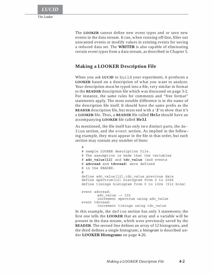
The Looker
Making a LOOKER Description File 4-2
LUCID
The LOOKER cannot define new event types and or save newevents in the data stream. It can, when running off-line, filter outunwanted events or modify values in existing events for savinga reduced data set. The WRITER is also capable of eliminatingcertain event types from a data stream, as described in Chapter 5.
Making a LOOKER Description File
When you ask LUCID to build your experiment, it produces aLOOKER based on a description of what you want to analyze.Your description must be typed into a file, very similar in formatto the READER description file which was discussed on page 3-2.For instance, the same rules for comments and “free format”statements apply. The most notable difference is in the name ofthe description file itself. It should have the same prefix as theREADER description file, but must end with a ‘.l’ to show that it’sa LOOKER file. Thus, a READER file called He3.r should have anaccompanying LOOKER file called He3.l.As mentioned, the file itself has only two distinct parts, the de-fine section, and the event section. As implied in the follow-ing example, they must appear in the file in that order, but eachsection may contain any number of lines:
## sample LOOKER description file.# The assumption is made that the variables# adc_value[12] and tdc_value (and events# adcread and tdcread) were defined# in the READER.#define adc_value[12],tdc_value previous datadefine spectrum[12] histogram from 0 to 2048define timings histogram from 0 to 1024 (512 bins)
event adcread:adc_value -= 102increment spectrum using adc_value
event tdcread:increment timings using tdc_value
In this example, the define section has only 3 statements; thefirst one tells the LOOKER that an array and a variable will bepresent in the data stream, which were previously saved by theREADER. The second line defines an array of 12 histograms, andthe third defines a single histogram; a histogram is described un-der LOOKER Histograms on page 4-26.
The Looker
LUCID
Making a LOOKER Description File 4-3The DEFINE Section Types of Variables
The two event statements introduce instructions which will beperformed when those named events are encountered in thedata stream. As the comments tell us, these events are named af-ter the original event names in the READER description file. Fur-thermore, the variables adc_value and tdc_value are notdefined in the LOOKER description file because they are READERvariables passed through the data stream. As we’ll see, you areallowed to define regular variables in the LOOKER, just as youcould in the READER.
The DEFINE Section
LUCID allows you to define variables in the LOOKER, just as ageneral programming language would. The LOOKER also has ac-cess to every variable that was previously saved in the READER.The LOOKER automatically makes those variables available toyou when it starts, or when they are changed during an experi-ment.
LUCID will warn you if you define a new variable for theLOOKER which you’ve also defined (and saved) from withinthe READER. Remember that only the names of variables thatwere saved by the READER are automatically defined for you.If you don’t want LUCID to automatically redefine the READERvariables, you may redefine them manually using the keywordsprevious data, as shown below. This forces the LOOKER tomake sure it is working with the correct READER.
Types of Variables
The LOOKER understands all types of variables that the READERknows about, except for CAMAC variables. When the LOOKERfinds a CAMAC variable in the data stream from a READER event,it is treated as an integer (or array of integers). It knows nothingabout accessing CAMAC or other hardware. On the other hand,the LOOKER understands different types of variables which theREADER can’t handle.In any case, variables are defined in exactly the same way as inthe READER file, as shown in the following example:
define energy real*4
This defines a single precision variable called energy. The samerules for defining READER variables apply in the LOOKER.

The Looker
Making a LOOKER Description File 4-4
LUCID
The DEFINE Section Defining Histograms
The format for defining variables is somewhat standard; theword define is followed by a list of names, which is followedby the type of variable:
define delta_e real*4define hits,ecounts,fcounts int*4define valid boolean
Notice that the word integer can be abbreviated to int.Variables which are expected to be seen in the data stream maybe defined in the LOOKER. Such variables have already been de-fined in the READER and defining some of them a second timein the LOOKER allows it to check that its using the right datastream. In fact new space for these variables isn’t allocated aswith other variables; the definitions are used only for “typechecking”. To define these READER variables, simply add thekeywords previous data after the variable names. For example:
define d_a previous datadefine o_tdc previous data int*2
The first example tells the LOOKER to make sure that some vari-able named d_a exists in the input stream. The second line makessure that o_tdc exists, but also makes sure that it is of type inte-ger*2.Defining READER variables again in the LOOKER is good pro-gramming practice, but is not required. A good compromise is todefine one or two commonly used variables from the READER.
Defining Histograms1
A histogram definition might appear as:define tdc_hist histogram from 0 to 256
which creates a simple one-dimensional histogram. A two-di-mensional histogram is defined similarly, such as:
define tdc_hist histogram from 0 to 256 and from 1024 to 2048
By default, histograms are created with each bin as type inte-ger*4. This data type can be changed, for instance, if a histogramcould have bin values beyond the range that this data type holds(roughly 4 billion counts per bin) then the histogram could bedefined as
define tdc_hist histogram real*8 from 0 to 256
1. A more complete description of Histogram Definitions appears in LOOKER Histograms onpage 4-26.
Defining DataStream Variables
The Looker
LUCID
Making a LOOKER Description File 4-5The DEFINE Section Defining Regions
The type of the histogram bin may be any of integer*2, inte-ger*4, real*4, or real*8.The default number of bins in a one-dimensional histogram is1024, and 128 for each dimension of a two-dimensional histo-gram. When this is inappropriate, the number of bins can bespecified as part of the definition:
define tdc_hist_2D histogram from 0 to 256 (1024 bins) and from 1024 to 2048 (16 bins)
The range of tdc_hist_2D specified using from and to are inclu-sive on the from value, but exclusive of the to value. In the aboveexample, the first dimension has a bin size of 0.25, the first binranges from 0.00 to 0.24, the second bin ranges from 0.25 to 0.49,and the last bin ranges from 255.75 to 255.99. Using range speci-fiers for first and last includes the high value of the range, caus-ing the bins to be that much wider.
Defining Regions1
Although regions are used with histograms, they are defined in-dependently in the DEFINE section of the looker. The importantpoint to remember is that a region must have the same numberof bins, dimensions, and array elements as the histogram thatwill be using the region. For the sake of clarity, regions shouldalso have the same ranges defined as their corresponding histo-grams.A simple two-dimensional region definition is almost identicalto a histogram definition:
define tdc_region region from 0 to 256 (1024 bins) and from 1024 to 2048 (16 bins) contains: (from 1024 to 1536) from 0 to 128 (from 1536 to 2048) from 128 to 256
The tdc_region could now be used with the tdc_hist_2D in theearlier example. The contains: entries define a checkerboard, asshown in Figure 4.1: the low half of the Y range (in parenthesis)with the low half of the X range, and the high half of the Y rangewith the high half of the X range. The contains: entry is optional,and if excluded, the region defaults to the entire range.
1. A more complete discussion of using Regions can be found in Region Definition on page 4-34.
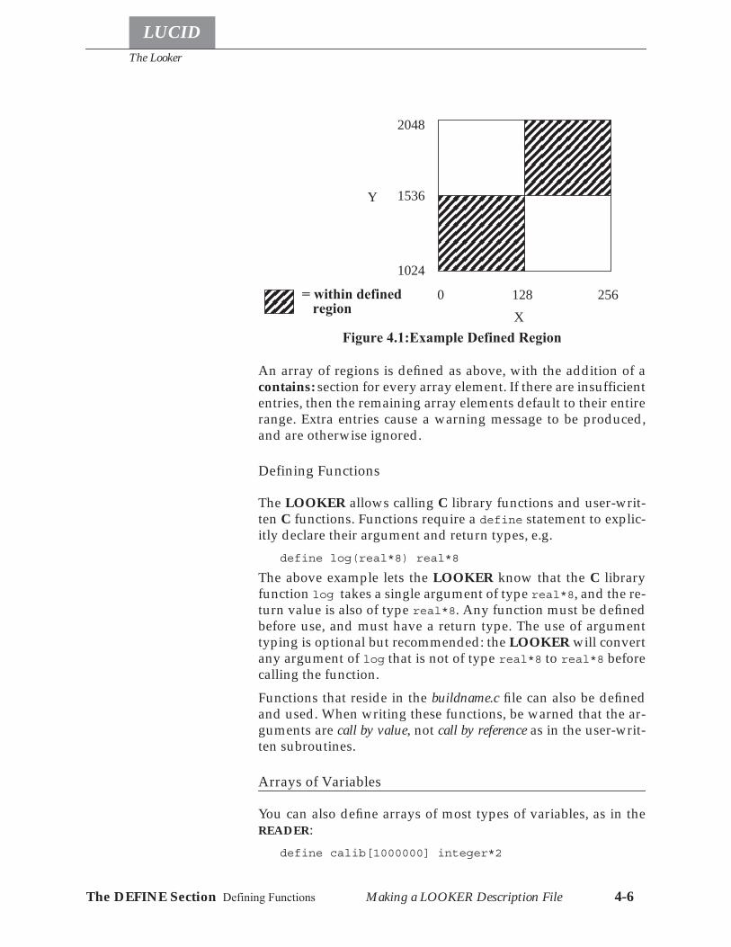
The Looker
Making a LOOKER Description File 4-6
LUCID
The DEFINE Section Defining Functions
An array of regions is defined as above, with the addition of acontains: section for every array element. If there are insufficiententries, then the remaining array elements default to their entirerange. Extra entries cause a warning message to be produced,and are otherwise ignored.
Defining Functions
The LOOKER allows calling C library functions and user-writ-ten C functions. Functions require a define statement to explic-itly declare their argument and return types, e.g.
define log(real*8) real*8
The above example lets the LOOKER know that the C libraryfunction log takes a single argument of type real*8, and the re-turn value is also of type real*8. Any function must be definedbefore use, and must have a return type. The use of argumenttyping is optional but recommended: the LOOKER will convertany argument of log that is not of type real*8 to real*8 beforecalling the function.Functions that reside in the buildname.c file can also be definedand used. When writing these functions, be warned that the ar-guments are call by value, not call by reference as in the user-writ-ten subroutines.
Arrays of Variables
You can also define arrays of most types of variables, as in theREADER:
define calib[1000000] integer*2
Y
1024
1536
2048
X0 128 256
Figure 4.1:Example Defined Region
= within defined region
The Looker
LUCID
Making a LOOKER Description File 4-7The DEFINE Section Groups of Variables
When defining a variable, the number of elements within the ar-ray must appear between brackets after the name. This exampleallocates room for a million integers, each containing two bytes.It also implies that you can have an unlimited amount of space.There is indeed a limit, and you should remember that using toomuch space can contribute to slowing down the computer,which is not desirable if the analysis is on-line. A LOOKER thattakes up too much space simply will not run.Array subscripts always start at zero, just as in the READER. Forexample, the array in the previous example can have subscriptsfrom 0 to 999999. All variables are guaranteed to have a zero val-ue after an experiment is rebuilt; but they are not zeroed out au-tomatically with every new experimental run.
Groups of Variables
LOOKER description files may come to contain hundreds of vari-ables as an experiment grows, and it may become difficult todeal with such a large number. To accommodate such experi-ments, the LOOKER recognizes groups of variables which can betreated as a common unit. Such an aggregate of variables is easyto define, as shown in this example:
define myhistograms groupdefine tdc0[8] hist from 0 to 128define tdc1[8] hist from 0 to 128define tdc2[8] hist from 0 to 128
endif
The histograms within the group can be used as they normallywould. The name myhistogram can also be used in a limitedfashion, and refers to all of the histograms within the group. Youcould assign 0 to myhistograms, thereby clearing all of the histo-grams in the group.Histograms and simple variables can be mixed within a group,as shown here:
define allvars groupdefine x, y, z int*4define elec,spec0[12] hist from 0 to 2048define adc2[12] previous data
endgroup
Simple assignment of a value to the group allvars will set allvariables, all histogram elements, and the current values of theevent data adc2 to zero (assuming the zeroing is occurring in anevent where adc2 was previously saved).
The Looker
Making a LOOKER Description File 4-8
LUCID
The EVENT Section Event Types
Some operations cannot be performed on allvars however,such as incrementing it as a histogram. If all variables within thegroup are histograms, like myhistograms was declared, then theincrement operation works as if you were repeating the opera-tion on each of the histograms in turn. The rules for using groupnames are restricted in the same way as using any other names;if an operation would fail on any of the members of the group,then the operation will fail on the entire group.You are allowed to nest group definitions within other groups.For example, the following definitions are acceptable:
define allvars groupdefine x, y, z int*4define histonly group
define elec,spec0[12] hist from 0 to 2048define tdcspec[96] hist
endgroupendgroup
All variables would be accessible by using allvars. Only the his-togram variables would be accessed when histonly was used.Although unlikely to be useful, one could increment all histo-grams at once with the same variable:
increment histonly using x
Another convenient use of variable groups is in the load state-ment. Rather than reading a single variable at a time, or listingout all the variables to the load statement, a group name couldbe used.Remember that all variables are still accessible by referring totheir names, regardless of which groups they are contained in.
The EVENT Section
The event section of the LOOKER description file is usuallymuch larger than the define section because it tells LUCID whatto do when a particular event is found in the data stream.
Event Types
The section consists of one or more event specifications, one afteranother in the description file. Each specification may containmany statements, but the first line must contain an event name,similar to a subroutine name in a programming language. Forexample, the statement
event electron:
The Looker
LUCID
Making a LOOKER Description File 4-9The EVENT Section Event Types
associates all subsequent statements (up to the next event speci-fication) with the event name electron. The statements whichfollow in the file will be performed whenever an electron eventis encountered. The following example shows a very simpleLOOKER description file which recognizes 3 different eventtypes in the data stream:
define e1,e2,e3 int*4
event photon:e1 = 1print "Found a Photon Event!"
event calib:e2 = 1print "Found a Calibration Event!"
event scaler:e3 = 1print "Found a Scaler Event!"
This is an overly simplistic example, meant to show the layout ofthe description file. Notice that the event section itself is quitesimilar in form to that in the READER description file; refer toThe EVENT Section on page 3-12.The rest of the statements in the event specification are similar tothe statements in most programming languages, allowing you toaccess any variables that were defined in the first half of the file,or previously in the READER. Histograms may be built up on anevent by event basis, since each event specification is repeatedfor every event of that type which is found in the data stream.Keep in mind that variables which were defined in the READERare only accessible if they were saved in the READER. Further-more, such variables will only be accessible within the specifica-tion for the event in which it was saved. For example, let’sassume that the READER had events named electron and had-ron, and also an array called scin_adc which was saved withinthe electron event. A LOOKER description file might look likethis:
define elec[12] histdefine scin_adc[12] previous data int*2
event hadron:print "Found an X-arm event!"
event electron:increment elec using scin_adc
The scin_adc array is used every time an electron event is found,and is used to build up a histogram. If an attempt was made touse scin_adc when a hadron event was encountered, an errormessage would be generated. LUCID knows that the READERdidn’t save scin_adc within the hadron event, and that the arrayhas no meaning when such an event is found in the data stream.

The Looker
Making a LOOKER Description File 4-10
LUCID
The EVENT Section Event Types
The LOOKER allows instructions to be performed at other times,not necessarily based on a particular type of event being encoun-tered. For instance, an event name is not required to appear be-fore a specification:
event:x += 1print "Found SOME type of event"
These statements will be performed when any type of event isencountered. Remember that you won’t be able to access anyREADER variables, since the LOOKER must know beforehandthat the variable will consistently appear for the given event.This can’t be guaranteed when any event can trigger the state-ments. This type of event specification might be used if you wantsome statistics about all events, for example (see above) thenumber of events processed.If a LOOKER performs a lot of computation when finding anevent which is quite common in the data stream, the entire ex-periment will slow down. The READER won‘t process any moredata until both the LOOKER or WRITER are ready to accept it.Fortunately, the LOOKER allows certain events to be processedonly when there is enough time to do so. Consider the followingexample:
define spec hist
event hadron (some):increment spec using adc
When on-line, the LOOKER knows that it needs to process onlysome of the hadron events, and will not hold up the READERwhile it works. If other hadron events go through the datastream while its processing a previous event, the LOOKER willignore them. By default, the LOOKER processes all events withthe given name, but the keyword (some) will make sure that theREADER won’t be held up while processing goes on.Similarly, if no event name is given and the statements are per-formed for all events, the (some) keyword may be used. For ex-ample:
event (some):print "An event has been seen!"
The print statement will be performed when any event is en-countered, but doing so will not keep the data stream from flow-ing.When off-line, the some keyword is ignored, as it is most impor-tant that the looker sees all events.
Processing Someof the Events
The Looker
LUCID
Making a LOOKER Description File 4-11The EVENT Section Event Types
Statements may also be performed whenever the beginning of anew run is encountered in the data stream. Important values andmessages could be printed when the analysis is ready to start, forexample.
define numevents int*4
event:numevents = numevents + 1
beginrun:print numevents, "seen so far"
This will produce a diagnostic at the beginning of each run spec-ifying how many events have been seen so far in the data stream.You could also use a beginrun section to automatically reset his-tograms or clear software scalers that are being kept.Similarly, it is possible to perform some actions when the end ofa Run is encountered in the data stream. Simply use “endrun:”instead of “beginrun:” in the first line of the specification. Keepin mind that variables saved in the READER are not accessiblewithin either of these specifications.To this point, the instructions within a LOOKER file can only beperformed after recognition of something in the data stream,such as event types or a Beginning of Run record. The LOOKERalso recognizes arbitrary commands from the User when thedata stream is being processed, so that internal status informa-tion may be printed, or variables may be reset.The following example shows a common use for this option:
define spect hist
event hadron:incr spec using adc
command "reset":spec = 0
A histogram is incremented every time a hadron event is en-countered, and that same histogram is cleared every time theuser issues a “reset” command. Again, variables saved in theREADER are not accessible from such statements. The com-mands may contain any type of text, and follow the same restric-tions as were placed by the READER. For more information, referto Keyboard Triggers on page 3-10.
Actions at the Beginningor End of a Run
User SpecifiedCommands
The Looker
Making a LOOKER Description File 4-12
LUCID
The EVENT Section Using Variables
In summary, there are five different “causes” which are recog-nized to start performing statements in the LOOKER:
event pion: event pion (some):event: event (some):beginrun:endrun:command "calibrate":
Using Variables
Variables in the LOOKER can be used in the same way as theywould be in the READER. For more information about what val-ues are acceptable and how constants may be specified, refer tothe READER section Using Variables on page 3-12.Some notable differences from READER variables should be re-alized here. First, double precision floating point variables areaccepted in the LOOKER. The following example demonstrates:
define d_energy[6] real*8
Second, histograms and regions are variables which the READERdoesn’t understand. These rather specialized variables areknown only in the LOOKER, but they are treated as variables inmost respects. For a description of these variables, refer toLOOKER Histograms on page 4-26, and Histogram Regions onpage 4-33.Third, the LOOKER knows nothing about CAMAC variables. Ifthe READER has saved values from CAMAC variables, theLOOKER will only see their values as data without caring abouttheir origin.Many other features of using variables are the same as they arein the READER. For instance, entire arrays of variables can beused as single entities by simply leaving out the subscript. Thefollowing segment would clear the first element within thenamed array:
define junk[100] int*4
beginrun:junk[0] = 0
The following code segment would clear the entire array at once:define junk[100] int*4
beginrun:junk = 0
The LOOKER has a few built-in variables, allowing easy accessto status information. The variables, and the information theymake available, are:
Built-in Variables
The Looker
LUCID
Making a LOOKER Description File 4-13The EVENT Section Calculations and Assign-
LUCIDrun current run numberLUCIDonline non-zero if performing on-line acquisitionLUCIDbytes number of data bytes seen this runLUCIDtime (off-line) timestamp of data recordLUCIDsequence (off-line) sequence number of data recordThe LUCIDtime and LUCIDsequence variables only work whenrunning off-line. The timestamp is a standard UNIX clock value,as returned by time()1. The number of bytes is a real*4 value, andthe other variables are integer values. These variables can beused anywhere.
Calculations and Assignment of Values
Arbitrary expressions are allowed in many places in LOOKERstatements, the most common being the assignment statement.
define new_e[20] integer*4define laststep[20] real*4define spect hist
event energy:new_e[0] = 10 * (laststep[0] /
130.2 + 2) ** 2
This example shows several features: mixed mode arithmetic isallowed; parentheses can be used for grouping; and lines may bebroken into pieces when they become too long. The list of sym-bols which the LOOKER recognizes as valid operators is shownin Figure 4.2.:Histograms cannot be used in expressions requiring a single re-sult. For instance, assume the assignment statement in the previ-ous example was changed to:
new_e[0] = 10 * (spect / 130.2 + 2) ** 2
LUCID would print an error message because this expression isexpected to yield a single result, and the spect histogram con-tains several values.
1. The UNIX timestamp is the number of seconds since 12:00 AM GMT, January 1, 1970. There are anumber of standard library routines that convert timestamps into usable values. See especially theUNIX manual entry for ctime() and localtime().
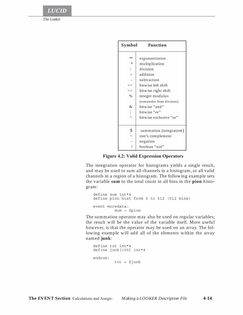
The Looker
Making a LOOKER Description File 4-14
LUCID
The EVENT Section Calculations and Assign-
The integration operator for histograms yields a single result,and may be used to sum all channels in a histogram, or all validchannels in a region of a histogram. The following example setsthe variable sum to the total count in all bins in the pion histo-gram:
define sum int*4define pion hist from 0 to 512 (512 bins)
event moredata:sum = $pion
The summation operator may also be used on regular variables;the result will be the value of the variable itself. More usefulhowever, is that the operator may be used on an array. The fol-lowing example will add all of the elements within the arraynamed junk:
define tot int*4define junk[100] int*4
endrun:tot = $junk
Symbol Function
** exponentiation* multiplication/ division+ addition- subtraction
<< bitwise left shift>> bitwise right shift% integer modulus
(remainder from division)& bitwise “and”| bitwise “or”^ bitwise exclusive “or”
$ summation (integration)~ one’s complement- negation! boolean “not”
Figure 4.2: Valid Expression Operators
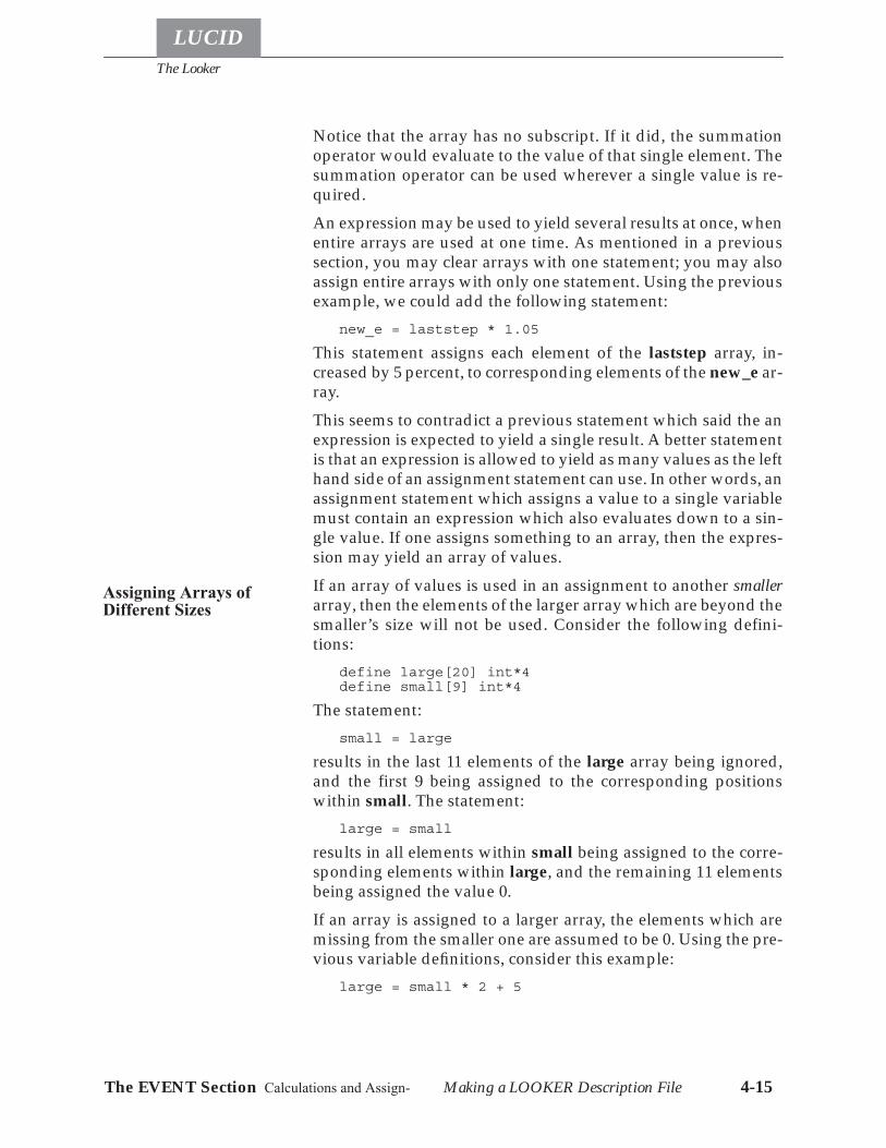
The Looker
LUCID
Making a LOOKER Description File 4-15The EVENT Section Calculations and Assign-
Notice that the array has no subscript. If it did, the summationoperator would evaluate to the value of that single element. Thesummation operator can be used wherever a single value is re-quired.An expression may be used to yield several results at once, whenentire arrays are used at one time. As mentioned in a previoussection, you may clear arrays with one statement; you may alsoassign entire arrays with only one statement. Using the previousexample, we could add the following statement:
new_e = laststep * 1.05
This statement assigns each element of the laststep array, in-creased by 5 percent, to corresponding elements of the new_e ar-ray.This seems to contradict a previous statement which said the anexpression is expected to yield a single result. A better statementis that an expression is allowed to yield as many values as the lefthand side of an assignment statement can use. In other words, anassignment statement which assigns a value to a single variablemust contain an expression which also evaluates down to a sin-gle value. If one assigns something to an array, then the expres-sion may yield an array of values.If an array of values is used in an assignment to another smallerarray, then the elements of the larger array which are beyond thesmaller’s size will not be used. Consider the following defini-tions:
define large[20] int*4define small[9] int*4
The statement:small = large
results in the last 11 elements of the large array being ignored,and the first 9 being assigned to the corresponding positionswithin small. The statement:
large = small
results in all elements within small being assigned to the corre-sponding elements within large, and the remaining 11 elementsbeing assigned the value 0.If an array is assigned to a larger array, the elements which aremissing from the smaller one are assumed to be 0. Using the pre-vious variable definitions, consider this example:
large = small * 2 + 5
Assigning Arrays ofDifferent Sizes
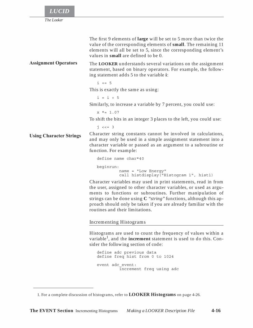
The Looker
Making a LOOKER Description File 4-16
LUCID
The EVENT Section Incrementing Histograms
The first 9 elements of large will be set to 5 more than twice thevalue of the corresponding elements of small. The remaining 11elements will all be set to 5, since the corresponding element’svalues in small are defined to be 0.The LOOKER understands several variations on the assignmentstatement, based on binary operators. For example, the follow-ing statement adds 5 to the variable i:
i += 5
This is exactly the same as using:i = i + 5
Similarly, to increase a variable by 7 percent, you could use:x *= 1.07
To shift the bits in an integer 3 places to the left, you could use:j <<= 3
Character string constants cannot be involved in calculations,and may only be used in a simple assignment statement into acharacter variable or passed as an argument to a subroutine orfunction. For example:
define name char*40
beginrun:name = "Low Energy"call histdisplay("Histogram 1", hist1)
Character variables may used in print statements, read in fromthe user, assigned to other character variables, or used as argu-ments to functions or subroutines. Further manipulation ofstrings can be done using C “string” functions, although this ap-proach should only be taken if you are already familiar with theroutines and their limitations.
Incrementing Histograms
Histograms are used to count the frequency of values within avariable1, and the increment statement is used to do this. Con-sider the following section of code:
define adc previous datadefine freq hist from 0 to 1024
event adc_event:increment freq using adc
1. For a complete discussion of histograms, refer to LOOKER Histograms on page 4-26.
Assignment Operators
Using Character Strings
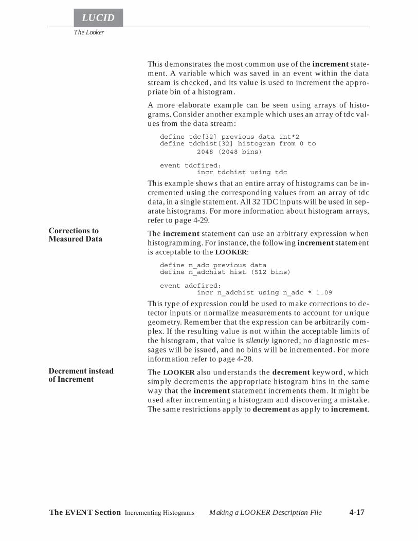
The Looker
LUCID
Making a LOOKER Description File 4-17The EVENT Section Incrementing Histograms
This demonstrates the most common use of the increment state-ment. A variable which was saved in an event within the datastream is checked, and its value is used to increment the appro-priate bin of a histogram.A more elaborate example can be seen using arrays of histo-grams. Consider another example which uses an array of tdc val-ues from the data stream:
define tdc[32] previous data int*2define tdchist[32] histogram from 0 to
2048 (2048 bins)
event tdcfired:incr tdchist using tdc
This example shows that an entire array of histograms can be in-cremented using the corresponding values from an array of tdcdata, in a single statement. All 32 TDC inputs will be used in sep-arate histograms. For more information about histogram arrays,refer to page 4-29.The increment statement can use an arbitrary expression whenhistogramming. For instance, the following increment statementis acceptable to the LOOKER:
define n_adc previous datadefine n_adchist hist (512 bins)
event adcfired:incr n_adchist using n_adc * 1.09
This type of expression could be used to make corrections to de-tector inputs or normalize measurements to account for uniquegeometry. Remember that the expression can be arbitrarily com-plex. If the resulting value is not within the acceptable limits ofthe histogram, that value is silently ignored; no diagnostic mes-sages will be issued, and no bins will be incremented. For moreinformation refer to page 4-28.The LOOKER also understands the decrement keyword, whichsimply decrements the appropriate histogram bins in the sameway that the increment statement increments them. It might beused after incrementing a histogram and discovering a mistake.The same restrictions apply to decrement as apply to increment.
Corrections toMeasured Data
Decrement insteadof Increment
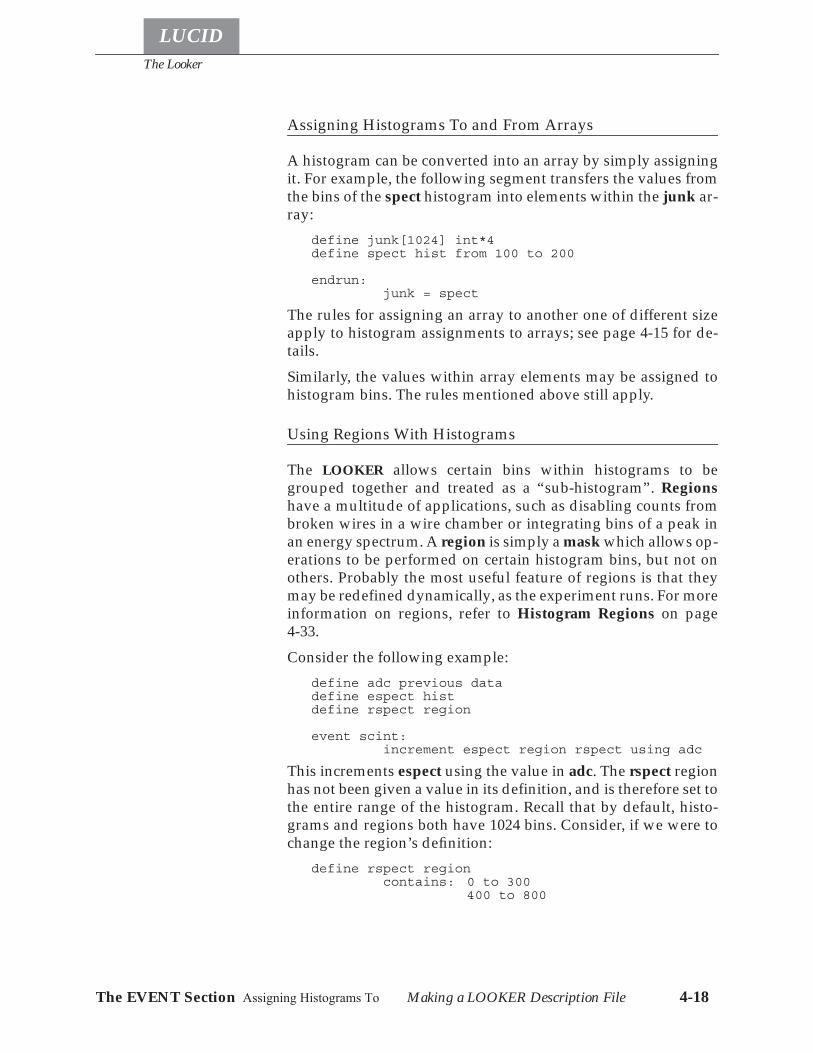
The Looker
Making a LOOKER Description File 4-18
LUCID
The EVENT Section Assigning Histograms To
Assigning Histograms To and From Arrays
A histogram can be converted into an array by simply assigningit. For example, the following segment transfers the values fromthe bins of the spect histogram into elements within the junk ar-ray:
define junk[1024] int*4define spect hist from 100 to 200
endrun:junk = spect
The rules for assigning an array to another one of different sizeapply to histogram assignments to arrays; see page 4-15 for de-tails.Similarly, the values within array elements may be assigned tohistogram bins. The rules mentioned above still apply.
Using Regions With Histograms
The LOOKER allows certain bins within histograms to begrouped together and treated as a “sub-histogram”. Regionshave a multitude of applications, such as disabling counts frombroken wires in a wire chamber or integrating bins of a peak inan energy spectrum. A region is simply a mask which allows op-erations to be performed on certain histogram bins, but not onothers. Probably the most useful feature of regions is that theymay be redefined dynamically, as the experiment runs. For moreinformation on regions, refer to Histogram Regions on page4-33.Consider the following example:
define adc previous datadefine espect histdefine rspect region
event scint:increment espect region rspect using adc
This increments espect using the value in adc. The rspect regionhas not been given a value in its definition, and is therefore set tothe entire range of the histogram. Recall that by default, histo-grams and regions both have 1024 bins. Consider, if we were tochange the region’s definition:
define rspect regioncontains: 0 to 300
400 to 800
The Looker
LUCID
Making a LOOKER Description File 4-19The EVENT Section Using Regions With Histo-
The histogram bins would still be incremented, but only if thevalue was greater than 0 and less than 300, or greater than 400but less than 800.If you want to use the bins of a histogram which are outside thoseaccepted by a region, the LOOKER allows you to use the notre-gion keyword. The increment statement from the previous ex-ample could be changed to:
increment espect notregion rspect using adc
This will increment bins which are outside of the rspect region’sbins.The LOOKER also understands the at symbol (@) as a regionspecifier. For instance, the previous example of:
increment espect region rspect using adc
could be change to a shorter form:incr rspect@espect using adc
Arrays of regions can be used with histograms or arrays of his-tograms in a variety of ways. Consider the following definitions:
define adc[32] previous data int*2define x hist from 0 to 100 (100 bins)define y[32] hist from 0 to 100 (100 bins)define rx region from 0 to 100 (100 bins)define ry[32] region from 0 to 100 (100 bins)
event newdata:incr rx@x using adc[0]
This seems quite straightforward, and increments bins in x usingthe first value in the adc array, via the region rx.Similarly, we could increment 32 histograms using the corre-sponding values from the adc array, using an array of 32 regions:
incr ry@y using adc
If we wanted to increment all 32 histograms from the 32 adc val-ues, but use the same region in each case, we could use:
incr ry[0]@y using adc
orincr rx@y using adc
In the first example, any subscript could be used to specify a sin-gle region. Using an array of regions is allowed only in conjunc-tion with an array of histograms. The following example isincorrect, and would cause an error message to be printed:
incr ry@x using adc
Using Arrays of Regions
The Looker
Making a LOOKER Description File 4-20
LUCID
The EVENT Section Incrementing Two Dimen-
Remember that the histogram and not the region is being incre-mented, and the region can only work in conjunction with a his-togram.An array of histograms can be incremented by an array of vari-ables; each variable within the array will be used to incrementthe corresponding histogram. If a single variable is used, then allhistograms in the array will be incremented in the same way1.If they are arrays, histograms and corresponding data must havethe same array size.
Incrementing Two Dimensional Histograms
Two dimensional histograms allow analysis of two variables atonce. For a description of two dimensional histograms, refer toDefining Two-Dimensional Histograms on page 4-36. Incre-ment statements are used in the same way, but two values mustbe given:
define adc[12] previous datadefine tdc[12] previous datadefine t_vs_e hist[64] from 0 to 1024 (64 bins)
and from 0 to 256 (64 bins)
event newdata:incr t_vs_e using adc,tdc
Notice that arrays of histograms and data have been used, in thesame way as they were with one dimensional histograms; thesame rules apply.The bits keyword may also be used in two dimensional histo-grams, with the same functionality. In fact, one variable may in-crement the histogram with the bit keyword, and the other useregular value increments. In any case, remember to put the wordbits immediately after the expression for the corresponding axis.See Histogramming Bit Positions on page 4-40 for a further de-scription of how this works.
Using Two Dimensional Regions
Two dimensional regions follow the same guidelines as one di-mensional regions, as described on page 4-18. Arrays of regionsare allowed, but the restrictions on array size apply here as theydo with one dimensional regions.
1. All histograms in an array have the same limits, binsize and number of bins, by definition.
The Looker
LUCID
Making a LOOKER Description File 4-21The EVENT Section The If-then-else Statement
The If-then-else Statement
The If-then-else statement allows the flow of execution to be al-tered within the LOOKER description file. There are two generalforms of the statement.First, an if statement contains comparisons between variablesand constants. For instance, the following statements check thata scaler value is below 30,000:
define scaler[6] previous data int*4
event checkdata:if scaler[0] .lt. 30000then
print "Overflow"else
print "Scaler O.K."endif
The then keyword is optional, but the endif keyword is re-quired.The else keyword and the statements associated with itare optional, too. An unlimited number of statements may be in-cluded within the then or else part of the statement, includingother if-then-else statements.Note that the comparison allows FORTRAN style keywords suchas .eq., .ge. and so forth. Standard comparison operators are alsoallowed, as found in C, such as <, >= and so forth. More complexcomparisons are allowed, such as:
if x .eq. 10 .and. y .lt. 100
Similarly, the C language conventions can be used:if( x == 10 && y < 100)
The LOOKER accepts a mixture of them as well. Parentheses arenot required around the comparison.The second form of the if statement is used to test the acceptabil-ity of histogram data. As described on page 4-17, any data whichis beyond the limits of a histogram is silently ignored; no errormessages or diagnostics are printed. If it is important to knowwhen a variable had an acceptable histogrammed value, the ifstatement can be used. Consider this example:
define tdc[32] int*4define eres[32] hist from 0 to 1024
event read_data:if incr eres using tdc
print "Acceptable value"else
print "Unacceptable value"endif
Simple Comparisons
Histogram AcceptanceTests
The Looker
Making a LOOKER Description File 4-22
LUCID
The EVENT Section The If-then-else Statement
The increment statement itself will be true or false dependingupon whether the variable was within the accepted range of thehistogram. Similarly, if a region is used and the value is not with-in the accepted bins of the region, the condition is consideredfalse. In this particular example, an array of histograms and val-ues are used; if any one value of the array is outside the acceptedlimits of the its histogram, the increment statement is consideredfalse.The LOOKER also allows checking data acceptance without ac-tually incrementing the histogram. The following exampleshows how a value can be passively checked without the histo-gram being changed:
define tdc[32],adc[32] int*4define teres[32] hist from 0 to 1024 (64 bins)
and from 0 to 64 (64 bins)
event read_data:if teres contains adc,tdc
print "Acceptable value"incr teres using adc,tdc
elseprint "Unacceptable value"
endif
This example shows two variables being checked at one time foracceptance in a two dimensional histogram. In fact, arrays ofvariables are being checked; if any of the values in either arrayare outside the limits of the teres histogram, the if statement willevaluate to false. Accordingly, a single variable can be tested bysimply using:
if nhist contains nvariable
Similarly, if the word bits comes after the variable, the bits willbe tested for acceptance, rather than the value of the variable.Keep in mind that the variables which are being used in these ex-amples can actually be complicated expressions. For example,consider this if statement which checks two variables for accep-tance in a two dimensional histogram:
if xyhist contains tdc[0]/tdc[1],adc[0]*0.98/adc[1]
The Looker
LUCID
Making a LOOKER Description File 4-23The EVENT Section The Repeat Statement
The Repeat Statement
The LOOKER allows an arbitrary number of statements to be re-peated, according to certain criteria. The standard form of the re-peat statement can be seen in the following example:
define x int*4
endrun:repeat x from 1 to 100 by 10
print "You should see 10 messages"endrepeat
The repeat statement must contain a variable, optionally fol-lowed by a beginning value, and ending value and a step size.All of the statements up to the endrepeat will be repeated so longas the variable is within the specified range. This particular ex-ample goes from 0 to 100 in steps of 10, changing the value of xat every iteration.The following example shows an infinite loop:
repeat xprint "Another iteration..."
endrepeat
The beginning, end and step portions of the statement are op-tional, allowing many variations:
repeat x from 1000 by 100repeat x to 10000repeat x by 2repeat x from 1
The variable which does the counting may be changed withinthe loop, to affect the control as you would expect. For instance,you might explicitly set it to the upper limit, so the loop will ter-minate. Repeat statements are allowed to be placed within otherrepeat statements.The variable’s initial value should be less than the loop’s finalvalue, and the increment must be positive. This is because thelooker always tests that the variable be less than or equal to thefinal value.
The Looker
Making a LOOKER Description File 4-24
LUCID
The EVENT Section Printing Values from the
Printing Values from the LOOKER
The print statement is quite general and allows the printing ofmessages to the user’s terminal screen. The messages may con-tain values from variables of any type. The following exampleshows the general format:
define x int*4
beginrun:x += 1print "Now starting Run ",x
Each item in the print statement must be separated from the nextitem by a comma, and character strings, constants and variablescan be printed in any order. Remember that using an array with-out a subscript in a print statement will print the entire array.If the user is not accessing the experiment when the print state-ment is performed, it will not be displayed but saved in the ex-periment’s log file.The print statement should be used with caution, since eachevent specification will be performed when the appropriateevent is encountered in the data stream. There could conceivablybe thousands of events processed per second, which impliesthousands of messages printed per second!Messages can also be printed directly to a file or to a user pro-gram:
define time(int*4) int*4print "Run ", LUCIDrun, " at ", time(0) to "runlog"print LUCIDrun to program "/home/exp000/bin/exparam"
Histograms can be saved to files using the write statement.There is little different between the write and the print state-ment: write requires that the output be directed to a file or pro-gram, and closes that file immediately after writing; variablessaved by write are in a fixed predefined format; print allowsconstants and expressions to be saved; write only allows onevariable per statement to be written.The syntax of the write statement is:
write [compressed] [binary|ascii] variable to[program] "destination"
Loading Histograms from Files or Programs
The reverse of the write statement is the load statement, whichallows reading previously saved or software generated histo-grams into the LOOKER. The load statement expects input inthe same format as that output by the write statement.
The Looker
LUCID
Making a LOOKER Description File 4-25The EVENT Section Setting Looker Variables
Setting Looker Variables Interactively
Users can set simple variables directly by using the read state-ment. A read statement looks like:
read variable [,variable ...] "prompt"
The user is prompted for input with the string prompt for each ofthe variables in the read statement. The value input from by theuser takes effect immediately. Be warned that analysis stopswhile the LOOKER is waiting for input, and this can cause theentire experiment to pause waiting for a response. This is bestused in a beginrun event for log information.
Using Your Own Subroutines
One important aspect of the LOOKER is the capability to performyour own subroutines whenever an event is encountered. Argu-ments may be passed to the subroutine, and may be variables,arrays or histograms. The following example shows how this istypically done:
define tdc[32] int*4define adc[32] previous data
event wirechamber:call tracking( tdc, adc)
The word call must appear immediately before your subrou-tine’s name. The parentheses must appear afterwards, whethervariables are being passed to it or not. If arguments are given,they must be separated by commas.This example shows a subroutine with two arrays being passedas arguments. The LOOKER currently understands subroutineswritten in C or FORTRAN, and will call them with the appropri-ate arguments. Histograms may also be passed as arguments,the size of the array will be equal to the number of bins in theoriginal histogram. All arguments are call by reference, which isthe normal method of passing arguments for FORTRAN. In C,all arguments must be pointers.Subroutines may be called at any point in the LOOKER descrip-tion file. If it prints something using a write statement (or printfin C), the message will be displayed on the user’s display screen,or in the experiment’s log file, as described under Printing Val-ues from the LOOKER on page 4-24.
The Looker
LOOKER Histograms 4-26
LUCID
The EVENT Section Using Your Own Subrou-
Your subroutines must exist in a file with the same name as yourdescription file, but having the appropriate suffix. For example,if your description files were contained within demo.r and/ordemo.l demo.w, your C language subroutines would be con-tained in a file named demo.c. Similarly, FORTRAN subroutineswould be contained within demo.f. You are allowed to use bothC and FORTRAN subroutines at the same time.Unfortunately, errors in your subroutine are not handled grace-fully in this version of LUCID, and the entire experiment will stopif your subroutine performs an illegal operation, such as an arraysubscript out of bounds, or an attempt to divide by zero.The LOOKER has three user-callable routines available: Lucid-savehist(), Lucidloadregion(), and Lucidloadvars(). All theseroutines must be declared as integer*4 within any looker pro-gram that calls them.Lucidsavehist("varname", "filename", flags) is similar to thewrite statement. The main differences are: strings variables canbe used to specify the variable name or the file name; selection oftype of save (compressed, binary vs. ascii, save to a program, binvs. value numbering) can be done at runtime; saving a mid-pointvalue is optional. The variable name is passed as a string (eithera string variable or a string constant) so the function can obtainall necessary information for saving the histogram.Lucidloadregion("regionname", "filename") is like a load state-ment for a region. The input format looks like a region definitionwithin the looker.Lucidloadvars("filename") is similar to a namelist read in FOR-TRAN. Each line in the input file is expected to have the name ofa variable declared in the looker, an optional subscript (whichmust be a constant), an equals sign, and a replacement value.The replacement values are converted to the type of the variable.String variables expect their values to be placed within doublequote marks.
LOOKER Histograms
Probably the most common practice followed when analyzingdata is to count the number of times that specific values arefound in a variable. For instance, it might be important to knowhow many times a certain variable contained the value 103, orhow many times the fourth bit position in a variable was set to a1.

The Looker
LUCID
LOOKER Histograms 4-27Histogram Definition Using Your Own Sub-
Histogram Definition
Normally, we have a separate counter for every possible valuethat a variable might contain; every time the variable changes,the counter which corresponds to its value is incremented byone. Keep in mind that a variable which contains N bits will need2N counters. For example, an 8 bit variable would require 256counters. Similarly, a common integer*4 variable would re-quire more than 4 billion counters! Unfortunately, the computercan’t manage 4 billion counters, so a compromise us usuallymade where several different values share the same counter.Regardless of the number of counters, we can visualize this pro-cess by thinking of a “bar graph”, with one bar representing eachcounter; the bars will increase in height whenever the variable isfound to contain the corresponding values. For example, we canvisualize a set of twenty-six counters like this:
As previously suggested, it is sometimes important to count thetimes when certain bits were set in a variable. The total value ofthe variable isn’t interesting, because each individual bit mightcorrespond to something different, such as a bank of detectorsfiring. When counting bits instead of variables, a 32 bit variable(integer*4) would have only 32 counters associated with it.Note that several counters might be incremented at once when avariable is checked; the value of 5 (binary 101) would cause 2 dif-ferent counters to count at the same time.In any case, a collection of counters is called a histogram, and LU-CID lets you define and use them as you would regular variables.A histogram can count the occurrence of any value or count thechanges to any bit position within a variable. Ideally, a histogramwill count these different values whenever the variable changes.
26 counters
The Looker
LOOKER Histograms 4-28
LUCID
Histogram Definition Defining Histograms
This action of determining the frequency at which different val-ues occur is a fundamental feature of the LOOKER.Each counter within a histogram is often referred to as a bin. Usu-ally, a histogram won’t contain more than a couple of thousandbins; LUCID lets you decide how many bins a histogram willcontain, and therefore what range of values will be counted byeach bin.The rule to remember is that all bins in a LUCID histogram havethe same width.Each individual bin must therefore have the same range of val-ues, but the entire histogram is allowed to count values in anyrange that can be contained in the variable. The resolution of anyhistogram is defined to be the width of a single bin, or the rangeof different values a bin will accept.
Defining Histograms
The following example shows how histograms can be defined:define e1,e2,e3 histogram from 0 to 1024
This allocates room for three histograms whose names are e1, e2and e3. Each one can count values from 0 up to but not including1024. If one of these histograms were given a variable with a val-ue of 1029 for example, it would simply ignore it. By default, LU-CID gives every histogram 1024 different bins. Therefore thedefault resolution is 1/1024th of the histogram’s acceptablerange. The keywords from and to name the limits of values ac-cepted by the histogram. Remember that the value of 1024 willnever be counted in this histogram. For now, we will assume thatonly integer variables are being counted, but real variables(floating point) can also be used, as described on page 4-31.Let’s look at another example:
define pions histogram from 100 to 126 (26 bins)
Bins

The Looker
LUCID
LOOKER Histograms 4-29Histogram Definition Defining Histograms
Imagine how this histogram would look after it has monitoredsome variable for awhile. The height of each vertical bar corre-sponds to the number of counts in each bin:
The definition says that only the values between 100 and 125 in-clusive are important, and values greater than or equal to 126 willnot be accepted. It seems apparent that most of the values thatwere checked so far were closer to 100 than 126, because thosebins have higher counts. We can also tell that 98 acceptable val-ues were encountered, because that is the total number of countsin all bins.Bins can count as high as 4 billion before they “wrap around” to0. If you think that your experiment might be very fast orlengthy, such that it will check billions of values, then you mayredefine your histograms to count to a higher range. Typically, abin is implemented as a 32 bit counter, but the LOOKER also al-lows the bins to be real numbers. The following example showshow this is done:
define pions real*8 histogram from 100to 126 (26 bins)
Keep in mind that the most efficient counter is the default1 whichthe LOOKER provides. Any other type of bin is rarely needed.You’re also allowed to have arrays of histograms.
define d1[10], d2[10] hist from 0 to 2048 (512 bins)
1. The default bin is of type int*4.
26 bins
last bin hascounted 2occurrences of thevalue 125
Number
2
5
10
0
first bin has encounteredthe value 100, 4 times
of valuesencountered
Number of Countsin each Bin
Histogram Arrays
The Looker
LOOKER Histograms 4-30
LUCID
Histogram Definition Defining Histograms
This example allocates two arrays of histograms, which willcount values only when between 0 and 2047 inclusive. There areactually 20 separate histograms defined in this statement, mak-ing up two separate arrays. Remember that arrays of variablesare accessed with subscripts that begin at zero, and arrays of his-tograms are treated similarly.In this same example, each histogram will contain only 512 bins,as specified with the keyword bins. Therefore, every bin willcount the occurrence of four consecutive values. For instance, thefirst bin (bin 0) would be incremented when a value of 0, 1, 2 or3 is found. Accordingly, the last bin will be incremented when avalue of 2044, 2045, 2046 or 2047 is encountered. Also notice thatthe word histogram can be abbreviated to be hist.In the following example, we define a histogram with 32 bins,counting values from 0 to 31 inclusive; This would probably beused to count changes in bit positions.
define pattern hist from 0 to 32 (32 bins)
Whether counting bit positions or different values within a vari-able, the histogram is defined in the same way; refer to page 4-40for a description of counting bit positions.For convenience, LUCID also recognizes definitions based on thefirst and last bins used in a histogram, rather than the limits ofvariable values accepted. This is better shown in the followingexample, where the keywords first and last are used:
define spectrum first 0 last 1023 (1024 bins)
This describes a histogram in which the first bin starts at 0, andthe last bin starts at 1023. Defining a histogram in this way en-sures that the upper “limit” is included in the counting proce-dure. The following definition would result in exactly the samehistogram:
define spectrum from 0 to 1024 (1024 bins)
The keywords from and to may seem more natural, but mightseem ambiguous in some cases, since the upper limit is never re-ally included in the counting. Using the first and last key-words introduce other conceptual problems however, such asthe acceptance of values within each bin. This is best shown byintroducing another keyword option, described in the next para-graphs.
Specifying HistogramBins Instead of Limits
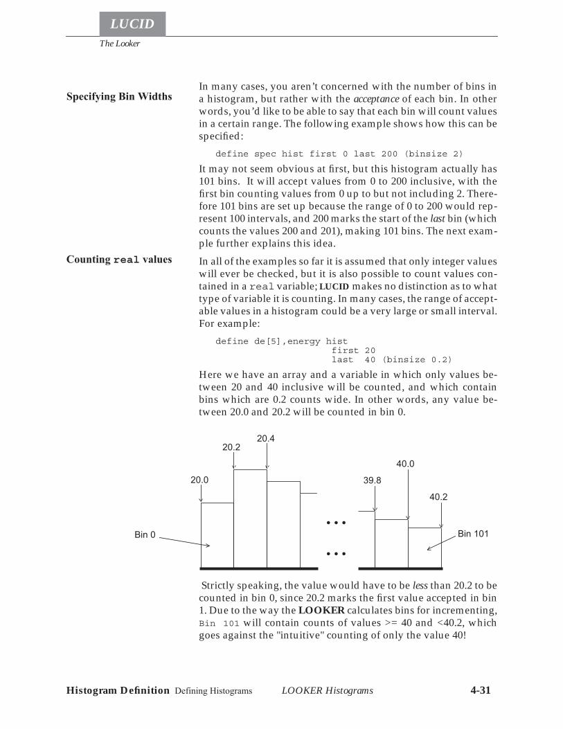
The Looker
LUCID
LOOKER Histograms 4-31Histogram Definition Defining Histograms
In many cases, you aren’t concerned with the number of bins ina histogram, but rather with the acceptance of each bin. In otherwords, you’d like to be able to say that each bin will count valuesin a certain range. The following example shows how this can bespecified:
define spec hist first 0 last 200 (binsize 2)
It may not seem obvious at first, but this histogram actually has101 bins. It will accept values from 0 to 200 inclusive, with thefirst bin counting values from 0 up to but not including 2. There-fore 101 bins are set up because the range of 0 to 200 would rep-resent 100 intervals, and 200 marks the start of the last bin (whichcounts the values 200 and 201), making 101 bins. The next exam-ple further explains this idea.In all of the examples so far it is assumed that only integer valueswill ever be checked, but it is also possible to count values con-tained in a real variable; LUCID makes no distinction as to whattype of variable it is counting. In many cases, the range of accept-able values in a histogram could be a very large or small interval.For example:
define de[5],energy hist first 20 last 40 (binsize 0.2)
Here we have an array and a variable in which only values be-tween 20 and 40 inclusive will be counted, and which containbins which are 0.2 counts wide. In other words, any value be-tween 20.0 and 20.2 will be counted in bin 0.
Strictly speaking, the value would have to be less than 20.2 to becounted in bin 0, since 20.2 marks the first value accepted in bin1. Due to the way the LOOKER calculates bins for incrementing,Bin 101 will contain counts of values >= 40 and <40.2, whichgoes against the "intuitive" counting of only the value 40!
Specifying Bin Widths
Counting real values
20.0
20.2
Bin 0
39.8
40.0
40.2
Bin 101
• • •
20.4
• • •
The Looker
LOOKER Histograms 4-32
LUCID
Histogram Definition Defining Histograms
This brings up a very important point in the LOOKER. A vari-able’s value is always included in the bin having a starting valuewhich is lower than the variable’s value. In other words, valuesare always rounded down to the next lowest bin’s starting val-ue1.In reconsidering the earlier example of
define spec hist first 0 last 200 (binsize 2),
bin 1 counts any values from 2 up to (but not including) 4, butthe last bin would actually start at 200. Using the first and last
keywords, the histograms could actually count certain valueswhich are larger than 200; a value greater than 200 and less than(but not including) 202 will be counted in the last bin.Negative numbers can be used to describe the range of accept-able values. For example:
define posn histogram first -1000 last 1000
This defines a histogram which will count values between -1000and 1000 inclusive, thereby containing 2001 bins. The only re-striction on the limits for acceptable values is that the first val-ue is numerically less than the last value. LUCID will warn youif the limits are backwards.Recall that by default, LUCID will allocate 1024 bins in a histo-gram, if no bin or binsize values are given. You may also omit thefrom or to keywords if you want. The default values of limitsfor the first and last channels are 0 and 1023 respectively. The fol-lowing example will therefore define a histogram with 1024 bins,the first one being 0 and the last being 1023.
define e1 hist
Some other restrictions should be mentioned here. The binsizevalue can’t be negative, and must divide the entire histograminto an exact number of bins. In other words, the difference be-tween the last and first bins must be a multiple of the binsize. LU-CID doesn’t care if you have a histogram with only 1 bin, but itwill complain if the bins don’t divide the total histogram intoequal pieces. For example:
define p1 hist first 0 last 99 (binsize 8)
1. To have the values rounded to the nearest bin boundary (higher or lower), you can add one half ofthe bin width (half the resolution) to the variable before histogramming.
How Histograms Count
Counting NegativeValues
Default first andlast histogram values
Restrictions
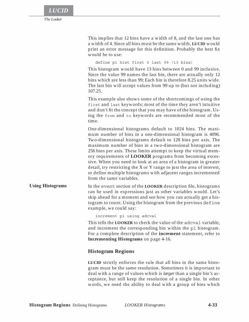
The Looker
LUCID
LOOKER Histograms 4-33Histogram Regions Defining Histograms
This implies that 12 bins have a width of 8, and the last one hasa width of 4. Since all bins must be the same width, LUCID wouldprint an error message for this definition. Probably the best fixwould be to use:
define p1 hist first 0 last 99 (13 bins)
This histogram would have 13 bins between 0 and 99 inclusive.Since the value 99 names the last bin, there are actually only 12bins which are less than 99; Each bin is therefore 8.25 units wide.The last bin will accept values from 99 up to (but not including)107.25.This example also shows some of the shortcomings of using thefirst and last keywords; most of the time they aren’t intuitiveand don’t fit the concept that you may have of the histogram. Us-ing the from and to keywords are recommended most of thetime.One-dimensional histograms default to 1024 bins. The maxi-mum number of bins in a one-dimensional histogram is 4096.Two-dimensional histograms default to 128 bins per axis. Themaximum number of bins in a two-dimensional histogram are256 bins per axis. These limits attempt to keep the virtual mem-ory requirements of LOOKER programs from becoming exces-sive. When you need to look at an area of a histogram in greaterdetail, try restricting the X or Y range to just the area of interest,or define multiple histograms with adjacent ranges incrementedfrom the same variables.In the event section of the LOOKER description file, histogramscan be used in expressions just as other variables would. Let’sskip ahead for a moment and see how you can actually get a his-togram to count. Using the histogram from the previous defineexample, we could say:
increment p1 using adcval
This tells the LOOKER to check the value of the adcval variable,and increment the corresponding bin within the p1 histogram.For a complete description of the increment statement, refer toIncrementing Histograms on page 4-16.
Histogram Regions
LUCID strictly enforces the rule that all bins in the same histo-gram must be the same resolution. Sometimes it is important todeal with a range of values which is larger than a single bin’s ac-ceptance, but still keep the resolution of a single bin. In otherwords, we need the ability to deal with a group of bins which
Using Histograms
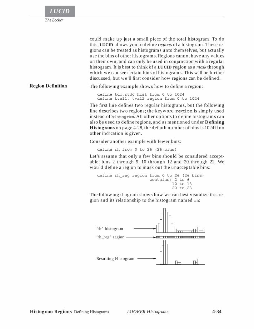
The Looker
LOOKER Histograms 4-34
LUCID
Histogram Regions Defining Histograms
could make up just a small piece of the total histogram. To dothis, LUCID allows you to define regions of a histogram. These re-gions can be treated as histograms unto themselves, but actuallyuse the bins of other histograms. Regions cannot have any valueson their own, and can only be used in conjunction with a regularhistogram. It is best to think of a LUCID region as a mask throughwhich we can see certain bins of histograms. This will be furtherdiscussed, but we’ll first consider how regions can be defined.The following example shows how to define a region:
define tdc,rtdc hist from 0 to 1024define tval1, tval2 region from 0 to 1024
The first line defines two regular histograms, but the followingline describes two regions; the keyword region is simply usedinstead of histogram. All other options to define histograms canalso be used to define regions, and as mentioned under DefiningHistograms on page 4-28, the default number of bins is 1024 if noother indication is given.Consider another example with fewer bins:
define rh from 0 to 26 (26 bins)
Let’s assume that only a few bins should be considered accept-able; bins 2 through 5, 10 through 12 and 20 through 22. Wewould define a region to mask out the unacceptable bins:
define rh_reg region from 0 to 26 (26 bins) contains: 2 to 6 10 to 13 20 to 23
The following diagram shows how we can best visualize this re-gion and its relationship to the histogram named rh:
Region Definition
’rh’ histogram
’rh_reg’ region
Resulting Histogram
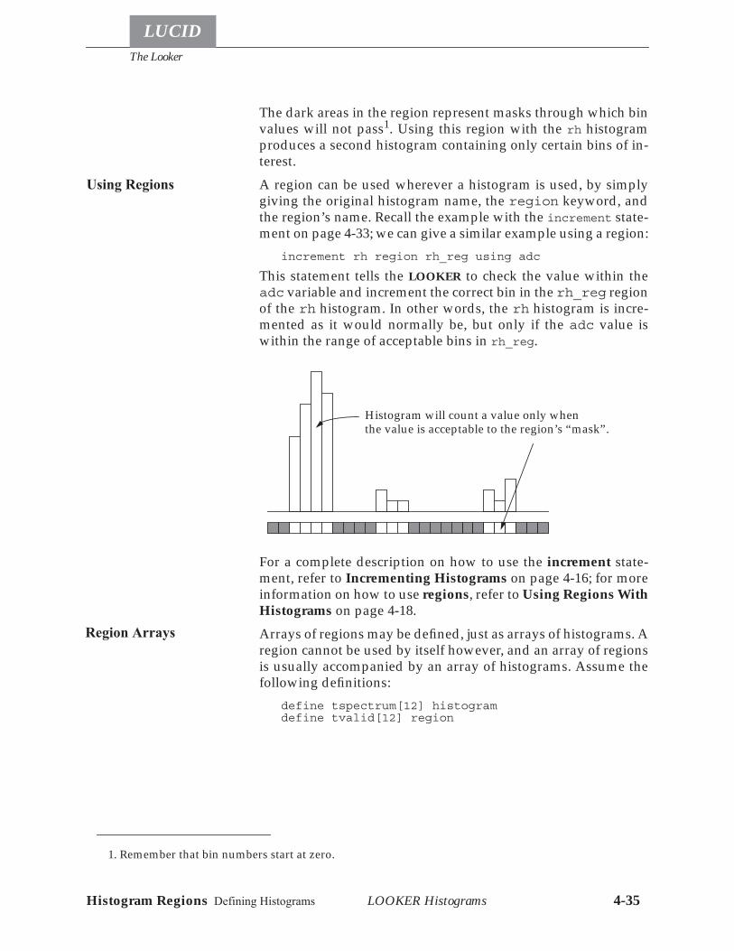
The Looker
LUCID
LOOKER Histograms 4-35Histogram Regions Defining Histograms
The dark areas in the region represent masks through which binvalues will not pass1. Using this region with the rh histogramproduces a second histogram containing only certain bins of in-terest.A region can be used wherever a histogram is used, by simplygiving the original histogram name, the region keyword, andthe region’s name. Recall the example with the increment state-ment on page 4-33; we can give a similar example using a region:
increment rh region rh_reg using adc
This statement tells the LOOKER to check the value within theadc variable and increment the correct bin in the rh_reg regionof the rh histogram. In other words, the rh histogram is incre-mented as it would normally be, but only if the adc value iswithin the range of acceptable bins in rh_reg.
For a complete description on how to use the increment state-ment, refer to Incrementing Histograms on page 4-16; for moreinformation on how to use regions, refer to Using Regions WithHistograms on page 4-18.Arrays of regions may be defined, just as arrays of histograms. Aregion cannot be used by itself however, and an array of regionsis usually accompanied by an array of histograms. Assume thefollowing definitions:
define tspectrum[12] histogramdefine tvalid[12] region
1. Remember that bin numbers start at zero.
Using Regions
Histogram will count a value only whenthe value is acceptable to the region’s “mask”.
Region Arrays
The Looker
LOOKER Histograms 4-36
LUCID
Defining Two-Dimensional Histograms
Regions and histograms both have 1024 bins by default. If we as-sume that an array of 12 tdc values exist, we could increment all12 histograms using the 12 corresponding tdc values, but only ifthey are acceptable to the corresponding 12 regions. This ratherelaborate process is described in detail later, but keep in mindthat only one statement is needed to do all the work:
increment tvalid@tspectrum using tdc
Note the alternate method of naming a region and histogrampair; using tvalid@tspectrum is the same as using tspectrum
region tvalid.Basically, regions make it very easy to determine if variables con-tain acceptable values, and can therefore let you cut unaccept-able events from the data stream, or increment histograms basedon ranges of values.Some restrictions should be mentioned at this point. In particu-lar, a region must have the same number of bins as any histo-gram with which it will be used. The notion of binsize has nomeaning to a region, since it may be used to mask out histogrambins of arbitrary resolution; it is only important that the regionand histogram have the same number of bins. Actually, bins canbe defined without limits, and can therefore be defined like this:
define validbins region (26 bins).
This validbins region can be used with any histogram having26 bins. Many programmers include limits in region definitions,specifically the same limits as are used in their associated histo-grams. This makes it easier to see which will be used together.
Defining Two-Dimensional Histograms
Histograms can be very useful when analyzing data. They arequite simple and essentially describe all of the changes made toa variable. We often need to know more information about avariable, particularly with respect to other variables. For exam-ple, we might want to count the occurrence of different valuesonly when some other variable has a value between say, 10 and20. In general terms, we want to count the occurrence of differentvalues in two different variables at the same time.
Region Restrictions
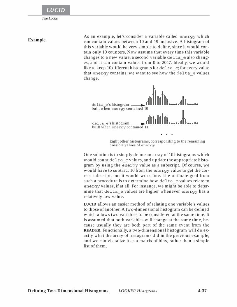
The Looker
LUCID
LOOKER Histograms 4-37Defining Two-Dimensional Histograms
As an example, let’s consider a variable called energy whichcan contain values between 10 and 19 inclusive. A histogram ofthis variable would be very simple to define, since it would con-tain only 10 counters. Now assume that every time this variablechanges to a new value, a second variable delta_e also chang-es, and it can contain values from 0 to 2047. Ideally, we wouldlike to keep 10 different histograms for delta_e; for every valuethat energy contains, we want to see how the delta_e valueschange.
One solution is to simply define an array of 10 histograms whichwould count delta_e values, and update the appropriate histo-gram by using the energy value as a subscript. Of course, wewould have to subtract 10 from the energy value to get the cor-rect subscript, but it would work fine. The ultimate goal fromsuch a procedure is to determine how delta_e values relate toenergy values, if at all. For instance, we might be able to deter-mine that delta_e values are higher whenever energy has arelatively low value.LUCID allows an easier method of relating one variable’s valuesto those of another. A two-dimensional histogram can be definedwhich allows two variables to be considered at the same time. Itis assumed that both variables will change at the same time, be-cause usually they are both part of the same event from theREADER. Functionally, a two-dimensional histogram will do ex-actly what the array of histograms did in the previous example,and we can visualize it as a matrix of bins, rather than a simplelist of them.
Example
delta_e’s histogrambuilt when energy contained 10
delta_e’s histogrambuilt when energy contained 11
Eight other histograms, corresponding to the remainingpossible values of energy
• • •
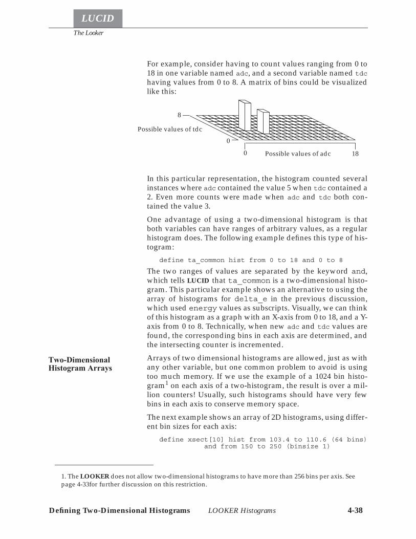
The Looker
LOOKER Histograms 4-38
LUCID
Defining Two-Dimensional Histograms
For example, consider having to count values ranging from 0 to18 in one variable named adc, and a second variable named tdc
having values from 0 to 8. A matrix of bins could be visualizedlike this:
In this particular representation, the histogram counted severalinstances where adc contained the value 5 when tdc contained a2. Even more counts were made when adc and tdc both con-tained the value 3.One advantage of using a two-dimensional histogram is thatboth variables can have ranges of arbitrary values, as a regularhistogram does. The following example defines this type of his-togram:
define ta_common hist from 0 to 18 and 0 to 8
The two ranges of values are separated by the keyword and,which tells LUCID that ta_common is a two-dimensional histo-gram. This particular example shows an alternative to using thearray of histograms for delta_e in the previous discussion,which used energy values as subscripts. Visually, we can thinkof this histogram as a graph with an X-axis from 0 to 18, and a Y-axis from 0 to 8. Technically, when new adc and tdc values arefound, the corresponding bins in each axis are determined, andthe intersecting counter is incremented.Arrays of two dimensional histograms are allowed, just as withany other variable, but one common problem to avoid is usingtoo much memory. If we use the example of a 1024 bin histo-gram1 on each axis of a two-histogram, the result is over a mil-lion counters! Usually, such histograms should have very fewbins in each axis to conserve memory space.The next example shows an array of 2D histograms, using differ-ent bin sizes for each axis:
define xsect[10] hist from 103.4 to 110.6 (64 bins) and from 150 to 250 (binsize 1)
1. The LOOKER does not allow two-dimensional histograms to have more than 256 bins per axis. Seepage 4-33for further discussion on this restriction.
0 18
0
8
Possible values of adc
Possible values of tdc
Two-DimensionalHistogram Arrays
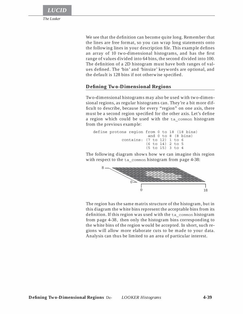
The Looker
LUCID
LOOKER Histograms 4-39Defining Two-Dimensional Regions De-
We see that the definition can become quite long. Remember thatthe lines are free format, so you can wrap long statements ontothe following lines in your description file. This example definesan array of 10 two-dimensional histograms, and has the firstrange of values divided into 64 bins, the second divided into 100.The definition of a 2D histogram must have both ranges of val-ues defined. The ‘bin’ and ‘binsize’ keywords are optional, andthe default is 128 bins if not otherwise specified.
Defining Two-Dimensional Regions
Two-dimensional histograms may also be used with two-dimen-sional regions, as regular histograms can. They’re a bit more dif-ficult to describe, because for every “region” on one axis, theremust be a second region specified for the other axis. Let’s definea region which could be used with the ta_common histogramfrom the previous example:
define protons region from 0 to 18 (18 bins) and 0 to 8 (8 bins) contains: (7 to 12) 1 to 6 (6 to 14) 2 to 5 (5 to 15) 3 to 4
The following diagram shows how we can imagine this regionwith respect to the ta_common histogram from page 4-38:
The region has the same matrix structure of the histogram, but inthis diagram the white bins represent the acceptable bins from itsdefinition. If this region was used with the ta_common histogramfrom page 4-38, then only the histogram bins corresponding tothe white bins of the region would be accepted. In short, such re-gions will allow more elaborate cuts to be made to your data.Analysis can thus be limited to an area of particular interest.
0 18
0
8

The Looker
LOOKER Histograms 4-40
LUCID
Histogramming Bit Positions Defining His-
Histogramming Bit Positions
Histograms typically count the occurrence of different valueswithin a variable. The LOOKER allows histograms to count thefrequency of bit values within an integer. For example, an exper-iment might contain an input register which has 16 bits in a wordcorresponding to 16 physical actions taking place. A commonpractice is to count the times each particular bit is being set:
For example, the least significant bit (rightmost in the diagram)in the integer might represent the occurrence of a special hard-ware trigger; if the bit is set1, the trigger has occurred. The sec-ond bit could be set if a calibration signal was presentsomewhere. In any case, the LOOKER allows you to count the oc-currences of these bits being set by using the bits keyword:
define inreg previous data int*2define bitcount hist from 0 to 32 (32 bins)
event readbits:incr bitcount using inreg bits
1. If a bit is set, it contains a 1. If cleared, it contains a 0.
Each bit correspondsto something of interest
Each bin counts the numberof times each bit has been set
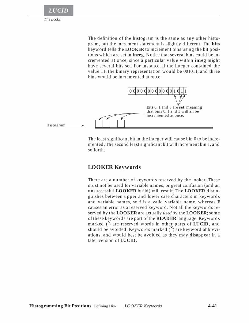
The Looker
LUCID
LOOKER Keywords 4-41Histogramming Bit Positions Defining His-
The definition of the histogram is the same as any other histo-gram, but the increment statement is slightly different. The bitskeyword tells the LOOKER to increment bins using the bit posi-tions which are set in inreg. Notice that several bins could be in-cremented at once, since a particular value within inreg mighthave several bits set. For instance, if the integer contained thevalue 11, the binary representation would be 001011, and threebins would be incremented at once:
The least significant bit in the integer will cause bin 0 to be incre-mented. The second least significant bit will increment bin 1, andso forth.
LOOKER Keywords
There are a number of keywords reserved by the looker. Thesemust not be used for variable names, or great confusion (and anunsuccessful LOOKER build) will result. The LOOKER distin-guishes between upper and lower case characters in keywordsand variable names, so f is a valid variable name, whereas Fcauses an error as a reserved keyword. Not all the keywords re-served by the LOOKER are actually used by the LOOKER; someof these keywords are part of the READER language. Keywordsmarked (*) are reserved words in other parts of LUCID, andshould be avoided. Keywords marked (X) are keyword abbrevi-ations, and would best be avoided as they may disappear in alater version of LUCID.
10 1 10 0 0 0 0 0 0 0 0 0 0 0
Bits 0, 1 and 3 are set, meaningthat bins 0, 1 and 3 will all beincremented at once.
Histogram

The Looker
LOOKER Keywords 4-42
LUCID
Histogramming Bit Positions Defining His-
A *B *
C *
F *
N *
allandasciibeginrunbinbinarybinsbinsizebitsbool Xbooleanbycallcamac *
charcharacter *
clear *
commandcompress X
compressedconstantly *
containsdatadataway*
decr X
decrement
def X
definediscard *
display *
elif *
elseendgroupendifendloopendrepeatendruneventeventsevery *
firstfromgrouphist X
histogramifincrincrementinhibit*initialize *int X
integerintegrateinto*
labellam * X
last
loadmicroseconds *
milliseconds *
minutes *
notregionorpreviousprintprogramreadready *
realrebinregionrejectrepea tresumerun*
save*
seconds *
sizeofsomesuspendrun*
thentimeout *totrigger *
uninhibit *
usingwait *
when*
write
LUCID
5-1
Chapter
5 The Writer
The third part of LUCID is called the WRITER, and its sole func-tion is to record the data produced by the READER and LOOKER.LUCID runs the WRITER when an experiment is built, and theuser is responsible for informing the writer of the destination ofthe data.Although the WRITER is only concerned with saving data, it iscapable of saving it in a variety of ways. For instance, you can tellthe WRITER to write certain events on a tape using LUCID, or towrite only as many of certain event types as will keeping the acquisitionfrom blocking.
Unlike the READER and LOOKER, there is no WRITER de-scription file. This allows changing writer destination informa-tion without requiring a rebuild of the experiment. However,destinations can only be changed when data acquisition is in aSTOPPED state. This helps to ensure the integrity of a run’sdata.Data is saved only is a LUCID-specific format. There are func-tions available to read this data into user-written C or FOR-TRAN programs, see Reading LUCID Data Files on page 7-10.LUCID also reads this data when running an off-line experi-ment, which is the easiest way to do more intricate calculationson your data.The rest of this chapter assumes familiarity with the Build Writerwindow described on page 2-11, or with the Modify writer listoption of the terminal-oriented lucid command, described brief-ly in The lucid Command on page 7-8.
The Writer
5-2
LUCID
Saving Event Data1
Although it is very easy to save different events in different plac-es, the most common requirement of the WRITER is to write everyevent that it finds in the data stream. Every event that the READ-ER can produce is saved, thereby writing all data to tape.You’re allowed to mix events and destinations in any fashion.For example, all events could be written to tape, but certain scal-er events could also written into a disk file.
Critical Data Destinations
The WRITER allows data output files to be flagged as critical des-tinations, as set by the Fail on Error setting in the writer window.When this is set for a data destination, the LUCID experimentwill stop when a write error occurs on output. This could be dueto filling a tape or disk partition, to an error on the output media,or an output program terminating. After such a failure, the ex-periment must be restarted. The resulting output files are possi-bly difficult to use: end-of-run summary records are missing, asare the LUCID-supplied end-of-run marks.When there is only one output device, Fail on Error should beset. With multiple devices, there are trade-offs. Fail on Error canbe set according to the results required.The idea behind data shadowing is to write the same data to twoor more destinations. All destinations are considered non-criti-cal. If one fails, the user can stop the experiment normally, andall other destinations will have proper end-run records and ap-propriate file marks. The drawback of the approach is the re-quirement for constant vigilance. The experimenter mustmonitor the message display window continuously, watchingfor an error message from any of the writers. The risk is that allthe messages could be missed, and once all writers have failed,the experiment still continues merrily along, sending all the datato the bit bucket!The safest approach when acquiring data is to have only one de-vice selected to fail on error. This device should be writing all oc-currences of all events. When this device fails, the acquisitionwill shut down and demand attention from the experimenter.
1. At the time this section was written, the WRITER software that distinguishes individual event re-quirements was not completed. It is hoped that the delay between documenting this software andwriting it is minimal.
Saving ALL Events
Data Shadowing
One Fail-on-error
The Writer
5-3
LUCID
Efficiency
The WRITER will work most efficiently when writing every eventto the same place. When it has to look at an event and decidewhere it should be written, the entire data stream will be forcedto slow down. It is best to save all types of acquisition events totape or disk, and then separate events later with a second off-lineLUCID data stream.The advantage of using the LUCID data file format is that yourdata file will be completely self-contained. Variable names, eventdescriptions and your original description files are saved to thedata stream whenever an experiment is started and then everytime you change a description file and rebuild. This means thatyou could tell LUCID to generate software to read an old datatape by simply telling it which tape drive to use! It will check thetape, extract the original description information, then write thesoftware to read the rest of the data.
Examples
The most common interaction with the WRITER is changingtapes in the destination tape drive. This is accomplished in thefollowing steps:
• Stop the current experiment (but don’t shut down) • Terminate the tape drive writer. In XLUCID, toggling the
SAVE state of the destination and APPLYing the changeis sufficient. In lucid, the tape drive must be deleted fromthe list and the list sent to the manager.
• After the writer process for the tape drive exits (this is in-dicated by a diagnostic message), remove the tape fromthe drive and insert a blank tape.
• Add the tape drive back to the list of destinations. InXLUCID, toggling the SAVE state on and APPLYing issufficient. In lucid, the tape drive must be re-added to thelist of output devices.
The most common use for multiple tapes is Data Shadowing. Itis only necessary to specify two output tape destinations that ac-cept all occurrences of all events. Both destinations should haveidentical Fail-on-error settings. Having both fail-on-error in-creases the chances of a tape write error aborting a run. If bothsilently exit, there is a remote chance that both destinations
Changing Tapes
Multiple Tapes

The Writer
5-4
LUCID
could stop writing with only a message to the view window. Ifthe experimenter misses both termination messages, the experi-ment would continue running but would not record any data.The only other feedback is the Writer: Bytes written this run box,which would stop updating the number of bytes acquired.
LUCID
6-1
Chapter
6 Conceptual Overview
How LUCID Works
When you tell LUCID to make an experiment, it takes your de-scription files and writes several computer programs. Each ofthe READER, LOOKER and WRITER are separate programs whichLUCID may produce, along with a separate program to accessCAMAC if that was specified. These programs are compiled,linked and executed automatically when you say make, but onlyif it’s necessary. For example, if you change your READER de-scription file slightly, then only part of the READER program willbe rewritten, recompiled and fit into the system. In any case, theprograms are started and after setting up communications withone another, will wait for your command.The data stream is on-line in this case, and the data is placed inshared memory. The experimenter may place certain restrictionson analysis in this case; for instance, he is allowed to have theLOOKER ignore some of the data in the interest of speed.The Play button tells the READER to replay data which has beenacquired earlier. The data stream is off-line in this case, and theREADER will pass the data through a “pipeline”, from which theLOOKER and/or WRITER can examine all of the data.When you ask LUCID to Make the software, it determines if thedata stream is on-line or off-line, and will only allow you to useone of either the Record or Play buttons.Whether on-line or not, the LOOKER will build up histogramsand perform other tests and calculations when new data arrives,possibly calling external subroutines that you’ve written before-hand. You can interact with the LOOKER via the lucid program,which allows you to view any or all data, and change the LOOK-ER’s data tests dynamically. New data, such as histograms, canbe included in the data stream for the WRITER to save.The WRITER records the data after everything else has finished.Data can be converted to an alternate format and saved to a diskfile, magnetic tape, or passed as input to another computer pro-
Looker
Writer
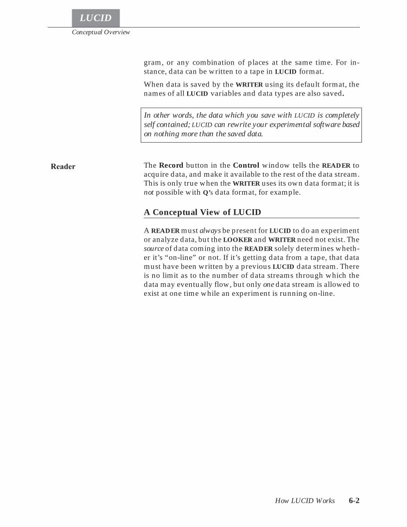
Conceptual Overview
How LUCID Works 6-2
LUCID
gram, or any combination of places at the same time. For in-stance, data can be written to a tape in LUCID format.When data is saved by the WRITER using its default format, thenames of all LUCID variables and data types are also saved.
The Record button in the Control window tells the READER toacquire data, and make it available to the rest of the data stream.This is only true when the WRITER uses its own data format; it isnot possible with Q’s data format, for example.
A Conceptual View of LUCID
A READER must always be present for LUCID to do an experimentor analyze data, but the LOOKER and WRITER need not exist. Thesource of data coming into the READER solely determines wheth-er it’s “on-line” or not. If it’s getting data from a tape, that datamust have been written by a previous LUCID data stream. Thereis no limit as to the number of data streams through which thedata may eventually flow, but only one data stream is allowed toexist at one time while an experiment is running on-line.
In other words, the data which you save with LUCID is completelyself contained; LUCID can rewrite your experimental software basedon nothing more than the saved data.
Reader
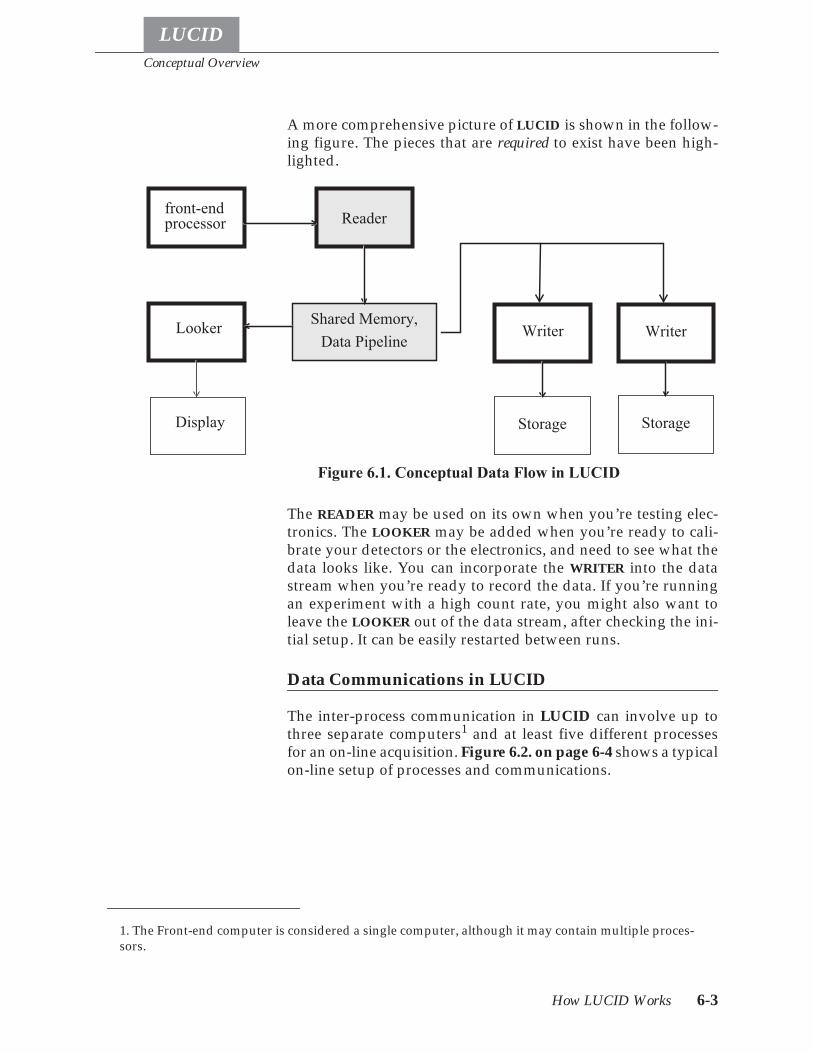
Conceptual Overview
How LUCID Works 6-3
LUCID
A more comprehensive picture of LUCID is shown in the follow-ing figure. The pieces that are required to exist have been high-lighted.
The READER may be used on its own when you’re testing elec-tronics. The LOOKER may be added when you’re ready to cali-brate your detectors or the electronics, and need to see what thedata looks like. You can incorporate the WRITER into the datastream when you’re ready to record the data. If you’re runningan experiment with a high count rate, you might also want toleave the LOOKER out of the data stream, after checking the ini-tial setup. It can be easily restarted between runs.
Data Communications in LUCID
The inter-process communication in LUCID can involve up tothree separate computers1 and at least five different processesfor an on-line acquisition. Figure 6.2. on page 6-4 shows a typicalon-line setup of processes and communications.
1. The Front-end computer is considered a single computer, although it may contain multiple proces-sors.
Reader
Shared Memory,Data Pipeline
front-endprocessor
Looker Writer
Display Storage
Writer
Storage
Figure 6.1. Conceptual Data Flow in LUCID
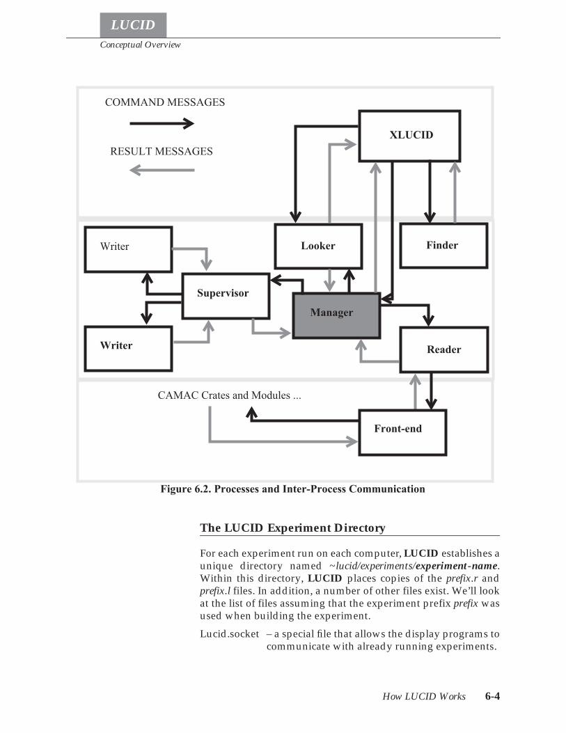
Conceptual Overview
How LUCID Works 6-4
LUCID
The LUCID Experiment Directory
For each experiment run on each computer, LUCID establishes aunique directory named ~lucid/experiments/experiment-name.Within this directory, LUCID places copies of the prefix.r andprefix.l files. In addition, a number of other files exist. We’ll lookat the list of files assuming that the experiment prefix prefix wasused when building the experiment.Lucid.socket – a special file that allows the display programs to
communicate with already running experiments.
XLUCID
Looker
Supervisor
Reader
Manager
FinderWriter
Writer
Front-end
CAMAC Crates and Modules ...
COMMAND MESSAGES
RESULT MESSAGES
Figure 6.2. Processes and Inter-Process Communication
Conceptual Overview
How LUCID Works 6-5
LUCID
prefix.l – the LOOKER program file, which was copiedfrom the user’s directory when the experimentwas built.
prefix.lsymtab – the looker symbol table, created when the exper-iment looker was built.
prefix.r the reader program file, which was copied fromthe user’s directory when the experiment readerwas built.
prefix.rsymtab– the reader symbol table, created when the exper-iment reader was built.
prefix.offlooker – the executable version of the off-line analysislooker.
prefix.offlooker.c – the C source generated automatically from theprefix.l file when the user specified off-line analy-sis.
prefix.offlooker.o – an intermediate file created when the prefix.-offlooker is generated.
logfile – where many of the LUCID messages go. Whenan obscure message is displayed elsewhere, it’s agood idea to look here for more information.
runno – the next run number to be used with data acqui-sition for this experiment.
seqno – a summary of the number of LUCID records ofeach record type.
prefix.frontend.c - the C source generated automatically from theprefix.r file when the user specified on-line acqui-sition from an VME front-end processor.
prefix.frontend.h - the C source generated automatically from theprefix.r file when the user specified on-line acqui-sition from a VME front-end processor. This fileincludes structure definitions for all the LUCIDevents, declarations for all the READER variablesrequested by the user, defines for the event num-bers, and the maximum event size.
prefix.m167- the executable version of the VME on-line acquisi-tion reader. This program is downloaded to theVME front-end computer.
prefix.m167.o - Intermediate file created when the prefix.m167program is generated.
prefix.c – a copy of the LOOKER C routines written by theuser.
Conceptual Overview
Programming Languages Used 6-6
LUCID
prefix.f – a copy of the LOOKER FORTRAN routineswritten by the user.
prefix_C.o – an intermediate object file generated from theprefix.c file.
prefix_F.o – an intermediate object file generated from theprefix.f file.
user – a file listing the account names of the people al-lowed to access the experiment on the currentcomputer. The first name in the list is the experi-ment administrator. If any of the other names is any-body, then any user with an account on theacquisition computer can connect to the experi-ment and control it.
Programming Languages Used
LUCID was written with the C programming language, and itproduces C programs to do your experiments. A compiler writ-ing program called YACC was used to understand the descrip-tion files, and generate the corresponding programs. YACC isalso written in C. The LOOKER allows subroutines written in Cor FORTRAN to be called while it is running.
LUCID
addclient 7-1
Chapter
7 Utility Programs and Subroutines
Utility Programs
There are a number of programs available for working with LU-CID data. A few of these programs are system administratorprograms, the rest are general use. In the following list, the pro-grams for system administrators are flagged with (system).
addclient (system)
The addclient program sets up the system files on the currentcomputer so LUCID can run. This program can only be run bythe super-user. No arguments are required, and there are noharmful effects caused by running the command on a computerthat had previously been set up.
copyrun
Copyrun copies runs (surprised?) from a LUCID data source toa destination. Which runs should be copied are determined bythe command line arguments. The command synopsis is:
copyrun [-o outputfile] [-i inputfile] -s sessionrun_number ... [ -s session run_number ... ] ...
The inputfile and the outputfile are LUCID data files; either maybe a tape drive. The session is the session number as shown by lu-cidview. The run_numbers listed after a session number are theruns that are to by copied. Runs from multiple sessions can becopied by adding additional session and run number specifica-tions.Copyrun supports the idea of remote tape drives. Although not aregular feature of SunOS, remote tape drives can be accessed byusing hostname:/dev/tape to access the device tape on ma-chine hostname, e.g. vega:/dev/nrst1 accesses the no-rewind rawscsi tape unit 1 on computer vega from any other computer.
Utility Programs and Subroutines
demolucid Utility Programs 7-2
LUCID
demolucid
The demolucid script installs in the current directory the neces-sary files for running the demo lucid experiment. Once the filesare installed, the xlucid program starts with the demo experi-ment. See Chapter 1 for more information on running the LU-CID demo.
extractrun
This program extracts a single run from the specified input andwrites it to the specified output. Usage is
extractrun [ -o outputfile ] inputfile run_number
If outputfile is not specified, then the run is written to the stan-dard output. Inputfile must be a valid LUCID data file, and run_-number should be a valid run number within that file.It is recommended that copyrun be used instead, as it allows thesame functionality with greater flexibility. For this very reason,extractrun may be removed from the LUCID system in the nearfuture.
findeot
The findeot command positions the tape in the tape drive speci-fied as the only command line argument between the two EOFmarks at the end of the data. If the name specified as a no-rewindtape drive, more data can then be added to the tape.The mt eom command should be equivalent to the findeot com-mand. However, early problems with eom on Exabyte drives at-tached to Sun workstations brought about the findeot command.Findeot will disappear when there is complete confidence thatthe majority of the free world has access to a properly function-ing mt eom command.
generate
Generate takes as input a LUCID data stream, and produces a Cinclude file from all the LREC_SYMBOL records found. This in-clude file can subsequently be used when writing custom code.For an existing on-line experiment, look for the already createdbuildname.frontend.h in the experiment directory.
Utility Programs and Subroutines
hv1440 Utility Programs 7-3
LUCID
hv1440
The hv1440 command communicates with the LeCroy 1440 highvoltage mainframe. Please refer to the manual page (man hv1440)for complete details.
hv4032
The hv4032 command communicates with the LeCroy 4032 highvoltage mainframe. Please refer to the manual page (man hv4032)for complete details.
intape
An early program to copy a LUCID data tape to disk. This is nowobsolete and selected for removal. Use the copyrun program in-stead.
lucid
The lucid command is a terminal-based control program for aLUCID experiment. This program pre-dates xlucid, and has notbeen kept up-to-date. It does allow simple access for monitoringa running experiment. Further discussion of this command canbe found in The lucid Command on page 7-8.
lucid_to_q
The lucid_to_q command attempts to translate LUCID data filesinto Q-format data. This program has not been used to any greatextent, and the documentation the program was based on maynot be current.Command syntax is:
lucid_to_q [ -ooutputfile ] inputfile ...
Where outputfile is the destination Q file, and the rest of the argu-ments are LUCID data files. If the output file is not specified,data is written to the standard output.There is no current documentation for this command.
lucidlog
The command syntax is:lucidlog [-N] experiment[@machine_name]
Utility Programs and Subroutines
lucidman Utility Programs 7-4
LUCID
Lucidlog displays the last N lines of the logfile for the named ex-periment. If machine_name is not specified, the log file on the cur-rent computer is used.
lucidman
The lucidman command prints out the LUCID manual pages onsystems lacking the MANPATH environment variable (e.g., ear-ly ULTRIX systems). It accepts the same arguments as the mancommand on the current machine.
lucidview
Lucidview displays the contents of the named files in human-readable form. Lucidview reads from the standard input if no filearguments are specified. The flag arguments control the amountand style of output produced. By default lucidview displays ev-erything.The flag arguments, and their effects, are:-c Display headers and contents of comment records.-d Display event data in data records (implies -e).-e Display data record headers and event headers
within the data records.-h Display LUCID record headers.-l Display headers and contents of ‘new LUCID ses-
sion' records.-n At every ‘end-run' record and at the end of each file
display the number of each type of event.-r Display headers and contents of reader description
records.-s Display headers and contents of event symbol table
records.-t Table of contents, showing run numbers and num-
ber of megabytes in each run.-v Display headers and contents of volume label
records.-wwidth Sets the maximum width of displayed event data to
width characters (default 80).
Utility Programs and Subroutines
netcamac Utility Programs 7-5
LUCID
netcamac
Netcamac sends CAMAC commands to a remote acquisitioncomputer for running on an attached CAMAC highway. Thecommand synopsis is:
netcamac [ -d level -D level ] frontend [ branch [crate [ module [ address [ function [ data ] ] ] ] ] ]
The -d and -D flags set the debugging level of the front end hostand the netcamac process, respectively. The frontend is thename of an acquisition computer. The branch, crate, module, ad-dress, and function specify the operation to be performed. Oper-ations which require data input need a data argument.If any of the arguments are missing, netcamac prompts for input.When all arguments are supplied, the program exits after thecommand is run. Otherwise, netcamac repeats the prompts to al-low running another command.
netcrateinit
Netcrateinit takes an acquisition CPU name, branch, and cratenumber as arguments. The crate is initialized.
nethv
The nethv program communicates with a LeCroy 2132 acrossthe network. The command takes the form:
nethv [ -i ] [ -ccontroller ] [ -pprompt ] [ file ...]
The controller should be specified as bNcNnNtN@host. Hostmust be a valid acquisition computer name. N is a number rep-resenting the branch, crate, station, and type of high-voltagemainframe (either 1440 or 4032). Nethv commands are read fromthe files named on the command line. The -i option tells nethv toread from the standard input after reading commands from thenamed files.help Produce a description of the rest of the commands.mainframe N
Make mainframe N the target of subsequent com-mands. The default 1440 mainframe address is 1and the default 4032 mainframe address is 16.
hvon Turn high voltage on.hvoff Turn high voltage off.set N V
Utility Programs and Subroutines
nethv Utility Programs 7-6
LUCID
set N-M V Set the demand value for channel N (or N throughM) to the value V. The set keyword can be omitted.Channel addresses range from 0 to 255 for 1440mainframes and from 0 to 31 for 4032 mainframes.For 1440 mainframes the sign of non-zero valuesmust agree with the polarity of the channel card. For4032 mainframes the sign of the value is ignored.Channel ranges are handled differently for 7 kVpods in 4032 mainframes. For these pods, a range af-fects every other channel. For example, assumingthat two 7 kV pods are installed in the first sockets,the command
set 0-6 5000
will set voltage channels 0, 2, 4 and 6 to 5000 volts.The command
set 1-7 300
will set the corresponding current limit channels(0c, 2c, 4c, and 6c) to 300 microamps.
display backup N-Mdisplay demand N-Mdisplay measured N-M
Display the backup, demand or measured value ofchannel N through M (a single channel number N isalso acceptable). The display keyword can be omit-ted. The demand and measured keywords can beabbreviated to their first character. If no channel ar-gument is specified the value (or values) from theprevious display command will be used.
ilimitilimit value If no value is specified this command displays the
positive and negative current limit settings. If a val-ue is specified the command set the appropriate cur-rent limit (according to the sign of the value). Thecurrent limit values are in units of approximately 10microamps. This command has no effect on 4032mainframes.
save filenameSave the demand and current limit values in thespecified filename. The name from the previoussave command is used if no filename is specified.The default file name is hv.save.
Utility Programs and Subroutines
qview Utility Programs 7-7
LUCID
quit Stop processing this file. Forces termination if theend of the file arguments has been reached or if theprogram is in interactive mode.
qview
Qview is similar to lucidview, but instead works with Q-formatdata files. Usage is
qview [ -cehd ] [ qfile ... ]
The flag arguments, and their effects are:-c Display comments in begin-run and comment records.-e Display event counters in end-run records.-h Display event headers in data records.-d Display event data in data records (implies -h).If no files are specified on the command line, Q data is expectedfrom the standard input.
readsara
Readsara communicates with the accelerator control system toretrieve and display values of named signals. The common useis to use readsara in a READER startup event or a timed statusevent to obtain values of accelerator settings and save them. Anynumber of signal names can be given on the command line, andreadsara prints out values in the same order.Listing the approximately 2000 different sara signals is beyondthe scope of this manual.
vme_console
The vme_console command is used to connect to the consoleport of the acquisition computer. This is useful for debuggingpurposes, and for resetting the acquisition computer. Usage issimply:
vme_console machine_name
where machine_name is the name of the acquisition computer. If aconnection cannot be made from the current machine, vme_con-sole gives a diagnostic message with the name of the computerto connect from.
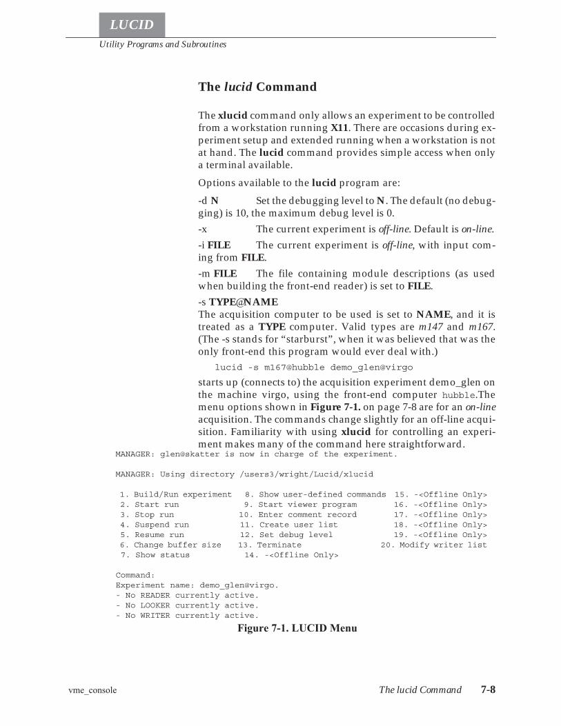
Utility Programs and Subroutines
vme_console The lucid Command 7-8
LUCID
The lucid Command
The xlucid command only allows an experiment to be controlledfrom a workstation running X11. There are occasions during ex-periment setup and extended running when a workstation is notat hand. The lucid command provides simple access when onlya terminal available.Options available to the lucid program are:-d N Set the debugging level to N. The default (no debug-ging) is 10, the maximum debug level is 0.-x The current experiment is off-line. Default is on-line.-i FILE The current experiment is off-line, with input com-ing from FILE.-m FILE The file containing module descriptions (as usedwhen building the front-end reader) is set to FILE.-s TYPE@NAMEThe acquisition computer to be used is set to NAME, and it istreated as a TYPE computer. Valid types are m147 and m167.(The -s stands for “starburst”, when it was believed that was theonly front-end this program would ever deal with.)
lucid -s m167@hubble demo_glen@virgo
starts up (connects to) the acquisition experiment demo_glen onthe machine virgo, using the front-end computer hubble.Themenu options shown in Figure 7-1. on page 7-8 are for an on-lineacquisition. The commands change slightly for an off-line acqui-sition. Familiarity with using xlucid for controlling an experi-ment makes many of the command here straightforward.
MANAGER: glen@skatter is now in charge of the experiment.
MANAGER: Using directory /users3/wright/Lucid/xlucid
1. Build/Run experiment 8. Show user-defined commands 15. -<Offline Only> 2. Start run 9. Start viewer program 16. -<Offline Only> 3. Stop run 10. Enter comment record 17. -<Offline Only> 4. Suspend run 11. Create user list 18. -<Offline Only> 5. Resume run 12. Set debug level 19. -<Offline Only> 6. Change buffer size 13. Terminate 20. Modify writer list 7. Show status 14. -<Offline Only>
Command:Experiment name: [email protected] No READER currently active.- No LOOKER currently active.- No WRITER currently active.
Figure 7-1. LUCID Menu

Utility Programs and Subroutines
vme_console The lucid Command 7-9
LUCID
1. Builds an experiment, prompting for build name (to findsource files), and whether to build a reader and/or a looker.
2. (ON-LINE) After an experiment has been built, this starts theacquisition.
3. (ON-LINE) This stops the acquisition for the current run.
4. (ON-LINE) The current run is paused.
5. (ON-LINE) A paused current run is resumed.
6. (ON-LINE) The buffer size used in communicating with thefront-end processor is changed. It should not be necessary touse this, as a save data statement in a user-triggered readercommand will flush the current buffer no matter thecontents.
7. Prints the current status of the READER, LOOKER, andWRITER.
8. Prints the list of user-defined commands in the reader andlooker.
9. Starts the Sunview-oriented viewer. Because of conflictbetween this and xlucid, this feature should be ignored. Donot use.
10. Creates a comment record and embeds it in the acquisitionstream. At the time of writing, this is the only way to create acomment record.
11. Modifies the user list of people who can access theexperiment. This does not handle the anybody user thatmatches all users.
12. Controls setting the debug level for the various parts of theLUCID system.
13. Shuts down the experiment and exits the lucid program.
14. (OFF-LINE) Opens an alternate data file for input.
15. (OFF-LINE) Starts the playback of the current data file.
16. (OFF-LINE) Stops the playback of the current data file.
17. (OFF-LINE) Rewinds the input data file.
18. (OFF-LINE) Skips forward to a specified run number.
19. (OFF-LINE) Closes the input data file.
Utility Programs and Subroutines
Accessing Networked Directories LUCID Functions and Subroutines 7-10
LUCID
20. Allows setting up writer devices and event lists for writerdevices. A separate menu is shown for this option which uses
a character menu rather than a numeric menu.
^C Quits the lucid program without shutting down the exper-iment. This can be entered at any time.
LUCID Functions and Subroutines
Accessing Networked Directories
The awd() and dwa() routines simplify the mapping of directorypaths on different computers. awd(pathname) fills in pathnamewith the name of the computer and the path on that computer re-quired to get to the current working directory. dwa(rempath,pathname) takes a remote path specification (as returned byawd()) and changes it into the proper path name for the currentmachine to reach the original path.Awd stands for Absolute Working Directory, and dwa stands forDirectory from Working Absolute. The fact that one name is thereverse of the other is entirely coincidence.
Reading LUCID Data Files
On occasion, it may become necessary to write data manipula-tion software that reads a LUCID data file. The following rou-tines simplify this.
Lucidopen(file) Opens the named file for reading. An error is returned if the filename is not valid, but no checking is done to ensure that the filecontains valid data.
Command: 20r/g/s/p/d/a/e/?: ?
r - read event name listg - get destination namess - save destination namesp - print destination infoP - print event namesd - delete destinationa - add destinatione - edit destination info
Figure 7-2.Writer Destination Menu
Utility Programs and Subroutines
Writing LUCID Data Records LUCID Functions and Subroutines 7-11
LUCID
Lucidfdopen(fd) Initializes for LUCID I/O on the argument file descriptor. Nochecking is done to ensure that the file descriptor references aLUCID data file, or that the file is positioned at a proper location.
Lucidread() Returns a pointer to the next LUCID record. On an error, a recordof type LUCIDerr is returned. On end-of-file, a NULL pointer isreturned.
Lucidskipdata() Returns the next non-data LUCID record. Error and EOF condi-tions are the same as above.
Lucidclose() Closes the LUCID data stream. If the data comes from a pipewhich was initiated by Lucidfdopen(), Lucidclose() must becalled before pclose().
Writing LUCID Data Records
This group of routines provide a low-level method of writingLUCID data files.
Lucidwopen(file) The named file is opened for output. If the file already exists, out-put will be appended to the end of the file.
Lucidwrite(data, size)The LUCID record referred to by data, containing size bytes, isadded to the current LUCID data block. If this fills the data buff-er, the buffer is written.
Lucidpad() The current buffer is filled with an LREC_NOTHING record,and written out.
Lucidweot() Two EOF marks are written to the output tape device, and thewrite head is then positioned between these marks.
Lucidwclose() The output file is closed.Unfortunately, the LF_ routines (below) do not make use of theLucidwrite routines. Until this changes, Lucidwrite() andLF_event() cannot be combined in the same program for pro-ducing a single output data stream.
Generating LUCID Data Files
The LF_ (Lucid Format) set of subroutines also write out LUCIDdata files, but provide a higher level of access to the user. UnlikeLucidwrite(), which expects all the proper LUCID records in thecorrect order, here records can be built up an element at a time.
LF_rsymtab(filename)The filename can either be NULL, indicating that there is norsymtab file and the user may define the events manually; or thename of a LUCID data file containing a valid symbol table. Thissymbol table gets copied to the output data stream.
Utility Programs and Subroutines
Low Level CAMAC Access LUCID Functions and Subroutines 7-12
LUCID
LF_define(eventno, eventname, varlist, count)LF_define() creates a symbol table entry for the event namedeventname, numbered eventno. Varlist is a pointer to an arrayof count Lucidvar variables that will be entered into the eventdescription record.
LF_open(filename, experiment, description)filename is opened for writing LUCID events. The output startswith a NEWSESSION record and a LUCIDFORMAT record. Ifan rsymtab file was given to the LF_rsymtab filename, then thesymbol table is copied from that file to the output file. IfLF_rsymtab was not called, then the experiment character stringis used to find a computer and experiment directory with anrsymtab file for buildname description. An example of look-ing for a description file is:
LF_open( "testdata", "demo_glen@virgo", "demo");
which opens the file testdata for output, and looks in the direc-tory /home/lucid/experiments/demo_glen on the computervirgo for the file demo.rsymtab.The description name and experiment name are used as part ofthe start session and start run entries. Run numbering starts at 1.
LF_event(eventno, buffer, nbytes)An event record is written out for type eventno, and is copiedfrom buffer and is expected to be nbytes in size. Nbytes is theunusual size of number of bytes rounded up to LUCIDALIGNboundary - 2. The two bytes subtracted at the end are filled inwith the event number. The easiest way to calculate this numberfor a non-compressed event is to define the structure for theevent, either using the generate program (page 7-2) or by includ-ing the on-line reader include file, and use the C operator sizeofto get the size of the event, then subtract two.
LF_close() The file opened for writing by LF_open is closed.
Low Level CAMAC Access
These routines allow camac operations to be remotely executedon a vme-based cpu. To call these routines it is necessary to in-clude -llucid on the compile command line.NetCamacOpen(), NetCamacPing(), NetCamacSetDebuglev(),NetCamac()

Utility Programs and Subroutines
High Voltage Access LUCID Functions and Subroutines 7-13
LUCID
NetCamacOpen (char *name)To perform a camac operation first open a communica-tions channel (a socket) using NetCamacOpen. The argument toNetCamacOpen is the host name of the target cpu (e.g., palomaror hubble). Only one connection can be operational at any giventime. Opening a second connection will cause the first to beclosed.
NetCamacPing() can be used to determine if the connection is still active. It iscalled by NetCamacOpen when the connection is established.
NetCamac (int b, int c, int n, int a, int f, long *data)Camac operations are performedby NetCamac where:
• b is the branch (an integer between 0 and 7), • c is the crate (an integer between 1 and 1), • n is the station (an integer between 1 and 23), • a is the address (an integer between 0 and 15), • f is the function (an integer between 0 and 31), • data is the address of a long integer, which is either the
source or destination of the data for the operation.NetCamacSetDebugLev(int level) sets the debugging level for CAMAC operations on
the front-end computer.DIAGNOSTICS: On error all routines send a message to stderrand return -1. If successful NetCamacOpen and NetCamacPing re-turn 0, NetCamac returns the status bits X (bit 0) and Q (bit 1).
High Voltage Access
The NetHv routines provide network access to the 4032 and 1440high voltage controllers. These routines are a standard part ofthe LUCID library.
NetHvOpen(char *name)name is a string specifying the high voltage controller to con-nect to. This string is of the format “bBRANCHcCRATEn-SLOTtTYPE@MACHINE”, where MACHINE is the front-endcomputer, BRANCH is the CAMAC branch to use, CRATE isthe crate in the branch, SLOT is the module address, and TYPEis the type of module (either 4032 or 1440) that is in that slot. adaemon process is started on the front-end computer, and it is thisprocess that the NetHv routines communicates with. 0 is re-turned on success, -1 on error.
NetHvFrame(int frame)Sets the frame entry for subsequent NetHv calls. frame must bebetween 1 and 16, inclusive.
NetHvOnoff(int onoff)If onoff is 1, the power supply is turned on. A value of 0 turnsthe power off. Any other value results in an error return.

Utility Programs and Subroutines
Reading Q-format Data LUCID Functions and Subroutines 7-14
LUCID
NetHvSetRampRate(int ramprate)Sets the ramp rate for the power supply. rampratemust be positive.
NetHvSetDemand(int first, int nchan, int value)Sets the demand to the specified value for the channels starting atfirst for the number of channels nchan.
NetHvGetDemand(int first, int nchan, int *value)Finds the demand for the specified range of channels and placesthe values in the array value.
NetHvGetMeasured(int first, int nchan, int *value)Reads the voltage levels for the specified range of channels, andplaces the result in the array pointed to by value.
NetHvSetIlimit(int ilimit)Sets the current limit to ilimit. If the limit is negative, the neg-ative limit is set, otherwise the positive limit is set.
NetHvGetIlimit(int *pos, int *neg)Finds the current limits and places them in pos and neg.
NetHvClose() Removes the connection to the high voltage controller.NetHvSetDebuglev(int level)Sets the debugging level for the net daemon software.
Reading Q-format Data
The Qread routines provide access to events in files written bythe Q software package. A C definition for the Q structures usedis found in /home/lucid/include/qformat.h. This software has notbeen extensively tested.
Qopen(char *name) The file referenced by name is opened to be read by the Qread()routine. 0 is returned on success, -1 on error.
Qread() The next Q record is read and returned as a pointer to the Qtape-header structure. This pointer can be cast to point to the appropri-ate structure type. NULL is returned on error or end-of-file.
Qclose() The Q data stream is closed.
Writing Q-format Data
These routines were originally intended to allow Q data to bewritten directly from the writer. Because the Q information is asubset of what LUCID records, experimenters must now recordtheir data in LUCID format, and then use the lucid_to_q pro-gram to convert their data. This allows complete access to the ex-periment data for independent analysis by different groups.
Utility Programs and Subroutines
LUCID Data Record Format Declarations LUCID Data File Format 7-15
LUCID
Qwopen(char *name)The file referenced by name is opened for writing of Q-formatdata.
Qwrite(void * lucidp)The lucid record pointed to by lucidp is converted to the propertype of Q record and then written. 0 is returned on success, -1 isreturned on error.
Qwclose() The output file is closed.
LUCID Data File Format
This section describes the format of LUCID data. Data defini-tions are shown using C syntax, and can be found in the LUCIDinclude file lucidformat.h.
LUCID Data Record Format Declarations
Output is always fixed length blocks (LUCIDBLKSIZE). Withinthese blocks are one or more records or parts of records. Routinesare provided to read and return the records to the calling routine.The calling routine never sees the underlying block structure.
#define LUCIDBLKSIZE (32*1024)
Alignment restrictions for specified types: must be powers of 2since (LUCIDALIGN_XXX - 1) is used as a bit mask.
#define LUCIDALIGN_RECORD 4#define LUCIDALIGN_SHORT 2#define LUCIDALIGN_LONG 4#define LUCIDALIGN_FLOAT 4#define LUCIDALIGN_DOUBLE 8
Number of bytes in variable names, user names, etc. All namesare null-terminated, so the maximum number of characters in aname is LUCIDNAMESIZE - 1.
#define LUCIDNAMESIZE 32
Utility Programs and Subroutines
LUCID Data Record Format Declarations LUCID Data File Format 7-16
LUCID
This header is contained within every record structure given be-low. The magic number ALWAYS comes first in EVERY record,and will make the byte ordering of the writing machine apparentto the reader.
struct Lucidheader {u_long lh_magic; identifies type of recordu_long lh_time; UNIX style time stampu_long lh_nbytes; number of bytes AFTER headeru_long lh_sequence;seq. number of this record
type};
The following is a list of values for the 'lh_magic' field in theheader structure. This identifies the type of record that follows:
LREC_FORMAT declares writing machine's binary representation.LREC_SYMBOL defines layout and variables used in an event's data record. See
struct Lucidsym below. This record will contain Lucidvar struc-tures to describe individual variables.
LREC_READER written when user changes experiment's reader description file.Essentially contains copy of the file itself. See struct Luciddescribebelow. Padded with newlines to a 0 modLUCIDALIGN_RECORD boundary.
LREC_LOOKER written when the Looker description file changes, similar toLREC_READER, above. See struct Luciddescribe below. Paddedwith newlines to a 0 mod LUCIDALIGN_RECORD boundary.
LREC_WRITER written when the Writer description file changes, similar toLREC_READER, above. See struct Luciddescribe below. Paddedwith newlines to a 0 mod LUCIDALIGN_RECORD boundary.
LREC_NEWVOLUMEmarks the transition from one file to another (typically a changeof tapes in a stacker). See struct Lucidvolume below.
LREC_NEWSESSIONwritten at the beginning of each session. See struct Lucidsessionbelow.
LREC_BEGINRUN written at the beginning of each distinct run, whenever the begin-run trigger is processed. See struct Lucidbegin below.
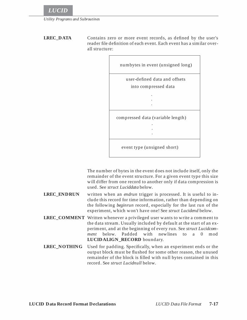
Utility Programs and Subroutines
LUCID Data Record Format Declarations LUCID Data File Format 7-17
LUCID
LREC_DATA Contains zero or more event records, as defined by the user'sreader file definition of each event. Each event has a similar over-all structure:
The number of bytes in the event does not include itself, only theremainder of the event structure. For a given event type this sizewill differ from one record to another only if data compression isused. See struct Luciddata below.
LREC_ENDRUN written when an endrun trigger is processed. It is useful to in-clude this record for time information, rather than depending onthe following beginrun record, especially for the last run of theexperiment, which won't have one! See struct Lucidend below.
LREC_COMMENT Written whenever a privileged user wants to write a comment tothe data stream. Usually included by default at the start of an ex-periment, and at the beginning of every run. See struct Lucidcom-ment below. Padded with newlines to a 0 modLUCIDALIGN_RECORD boundary.
LREC_NOTHING Used for padding. Specifically, when an experiment ends or theoutput block must be flushed for some other reason, the unusedremainder of the block is filled with null bytes contained in thisrecord. See struct Lucidnull below.
numbytes in event (unsigned long)
user-defined data and offsetsinto compressed data
compressed data (variable length)
event type (unsigned short)
.
.
.
.
.
.
Utility Programs and Subroutines
LUCID Data Record Format Declarations LUCID Data File Format 7-18
LUCID
LREC_ERROR Used to indicate error reading data. Only the lh_magic structureelement is valid. All other structure entries are zero.
#define LREC_FORMAT 0x553001AAL#define LREC_SYMBOL 0x553002AAL#define LREC_READER 0x553003AAL#define LREC_LOOKER 0x553004AAL#define LREC_WRITER 0x553005AAL#define LREC_NEWVOLUME 0x553006AAL#define LREC_NEWSESSION 0x553007AAL#define LREC_BEGINRUN 0x553008AAL#define LREC_DATA 0x553009AAL#define LREC_ENDRUN 0x55300AAAL#define LREC_COMMENT 0x55300BAAL#define LREC_NOTHING 0x55300CAAL#define LREC_ERROR 0x55300DAAL
Event source values:#define LSRC_UNKNOWN 0#define LSRC_READER 1#define LSRC_LOOKER 2
The following structure is written near the beginning of a vol-ume to allow software to determine the architecture of the writ-ing machine. It includes a constant in single and doubleprecision format.
#define LUCID_FLOATCHECK (1.25)struct Lucidformat {
struct Lucidheader lf_head; standard recordheader
double lf_double; double precision format ofsource
float lf_float; floating format of source};
Event definitions consist of the following Lucidsym structurewhich will contain zero or more variable definitions. The orderof the definitions dictates their order within the data record. Zerovariables indicates no data saved.Different types of variables that can be saved.
#define LVAR_UNKNOWN 0#define LVAR_BOOL 1#define LVAR_CHAR 2#define LVAR_SHORT 3#define LVAR_LONG 4#define LVAR_FLOAT 5#define LVAR_DOUBLE 6#define LVAR_TYPEMASK 077 mask for basic type

Utility Programs and Subroutines
LUCID Data Record Format Declarations LUCID Data File Format 7-19
LUCID
#define LVAR_PADNAME "<<pad>>"name for all pad bytes
#define LVAR_HISTFLAG 0100histogram bit or'd in
#define LHIST_MAXDIMS 2maximum histogram dimensions
#define MAXHISTBINS 4096maximum 1 dimensional hist bins
#define MAXSCATBINS 256maximum 2 dimensional hist bins
Data compression variations#define LCMP_SHORTSHORT 1
Short channel:short data#define LCMP_LONGSHORT 2
Long channel:short data:short pad#define LCMP_LONGLONG 3
Long channel:long/float data#define LCMP_LONGDOUBLE 4
Long channel:long pad:double data#define LCMP_HISTOGRAM 5
Short X channel:short Y channel:long/floatdata#define LCMP_DOUBLEHISTOGRAM 6
Short X channel:short Y channel:longpad:double data#define LCMP_VARIABLE 7
New-style compression
A variable stored using LCMP_VARIABLE data compressionappears in the data stream as a variable-length and fixed-lengthcomponent. The variable-length components appears after allfixed-length data. Indices into the variable-length data are storedamong the fixed-length variables. The offsets are the offsets(from the beginning of the event) of the first and just-past-the-last byte of the associated variable. For example:
event e1:read and save v1read compress and save v2read and save v3read compress and save v4read and save v5
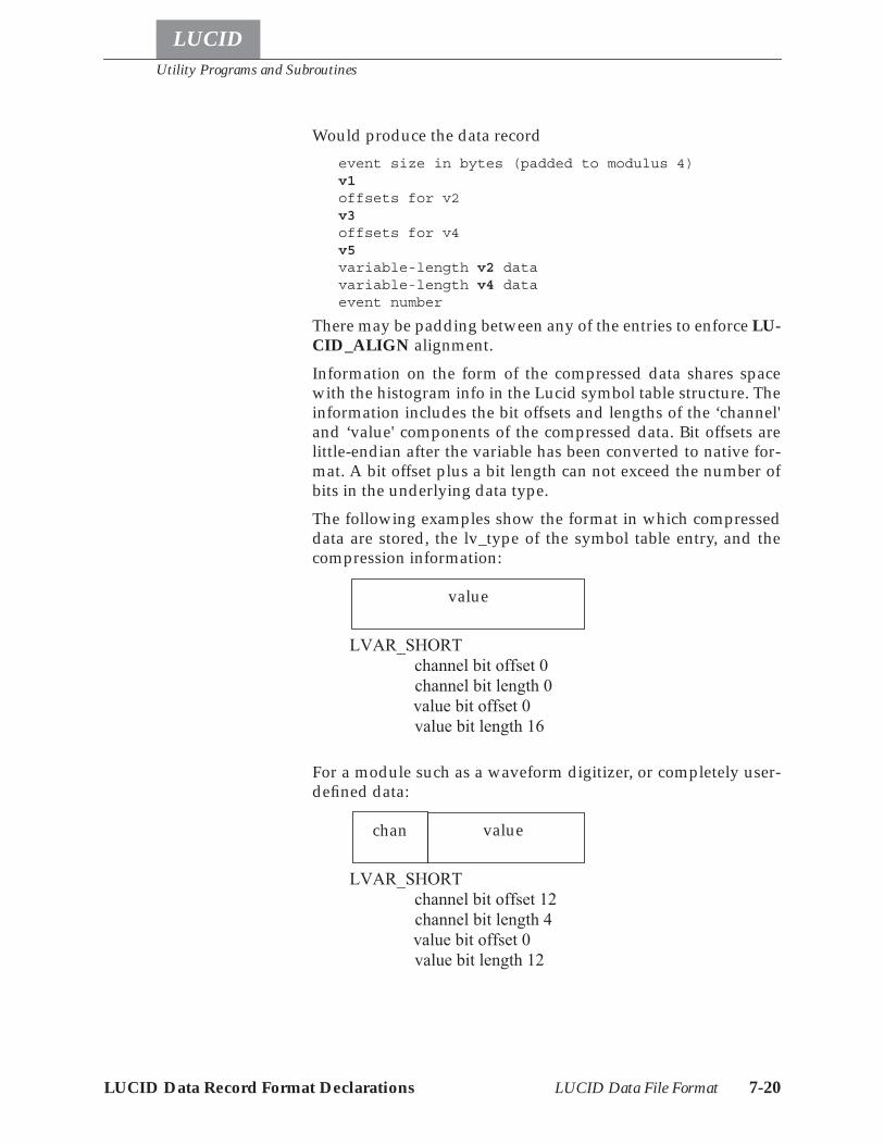
Utility Programs and Subroutines
LUCID Data Record Format Declarations LUCID Data File Format 7-20
LUCID
Would produce the data recordevent size in bytes (padded to modulus 4)v1offsets for v2v3offsets for v4v5variable-length v2 datavariable-length v4 dataevent number
There may be padding between any of the entries to enforce LU-CID_ALIGN alignment.Information on the form of the compressed data shares spacewith the histogram info in the Lucid symbol table structure. Theinformation includes the bit offsets and lengths of the ‘channel'and ‘value' components of the compressed data. Bit offsets arelittle-endian after the variable has been converted to native for-mat. A bit offset plus a bit length can not exceed the number ofbits in the underlying data type.The following examples show the format in which compresseddata are stored, the lv_type of the symbol table entry, and thecompression information:
For a module such as a waveform digitizer, or completely user-defined data:
value
LVAR_SHORTchannel bit offset 0channel bit length 0value bit offset 0value bit length 16
value
LVAR_SHORTchannel bit offset 12channel bit length 4value bit offset 0value bit length 12
chan
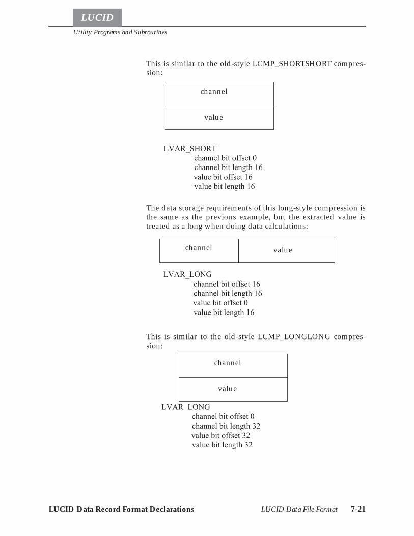
Utility Programs and Subroutines
LUCID Data Record Format Declarations LUCID Data File Format 7-21
LUCID
This is similar to the old-style LCMP_SHORTSHORT compres-sion:
The data storage requirements of this long-style compression isthe same as the previous example, but the extracted value istreated as a long when doing data calculations:
This is similar to the old-style LCMP_LONGLONG compres-sion:
value
LVAR_SHORTchannel bit offset 0channel bit length 16value bit offset 16value bit length 16
channel
value
LVAR_LONGchannel bit offset 16channel bit length 16value bit offset 0value bit length 16
channel
LVAR_LONGchannel bit offset 0channel bit length 32value bit offset 32value bit length 32
value
channel
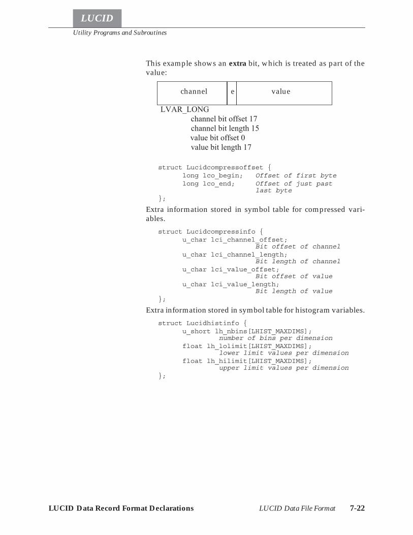
Utility Programs and Subroutines
LUCID Data Record Format Declarations LUCID Data File Format 7-22
LUCID
This example shows an extra bit, which is treated as part of thevalue:
struct Lucidcompressoffset {long lco_begin; Offset of first bytelong lco_end; Offset of just past
last byte};
Extra information stored in symbol table for compressed vari-ables.
struct Lucidcompressinfo {u_char lci_channel_offset;
Bit offset of channelu_char lci_channel_length;
Bit length of channelu_char lci_value_offset;
Bit offset of valueu_char lci_value_length;
Bit length of value};
Extra information stored in symbol table for histogram variables.struct Lucidhistinfo {
u_short lh_nbins[LHIST_MAXDIMS];number of bins per dimension
float lh_lolimit[LHIST_MAXDIMS];lower limit values per dimension
float lh_hilimit[LHIST_MAXDIMS];upper limit values per dimension
};
LVAR_LONGchannel bit offset 17channel bit length 15value bit offset 0value bit length 17
valuechannel e
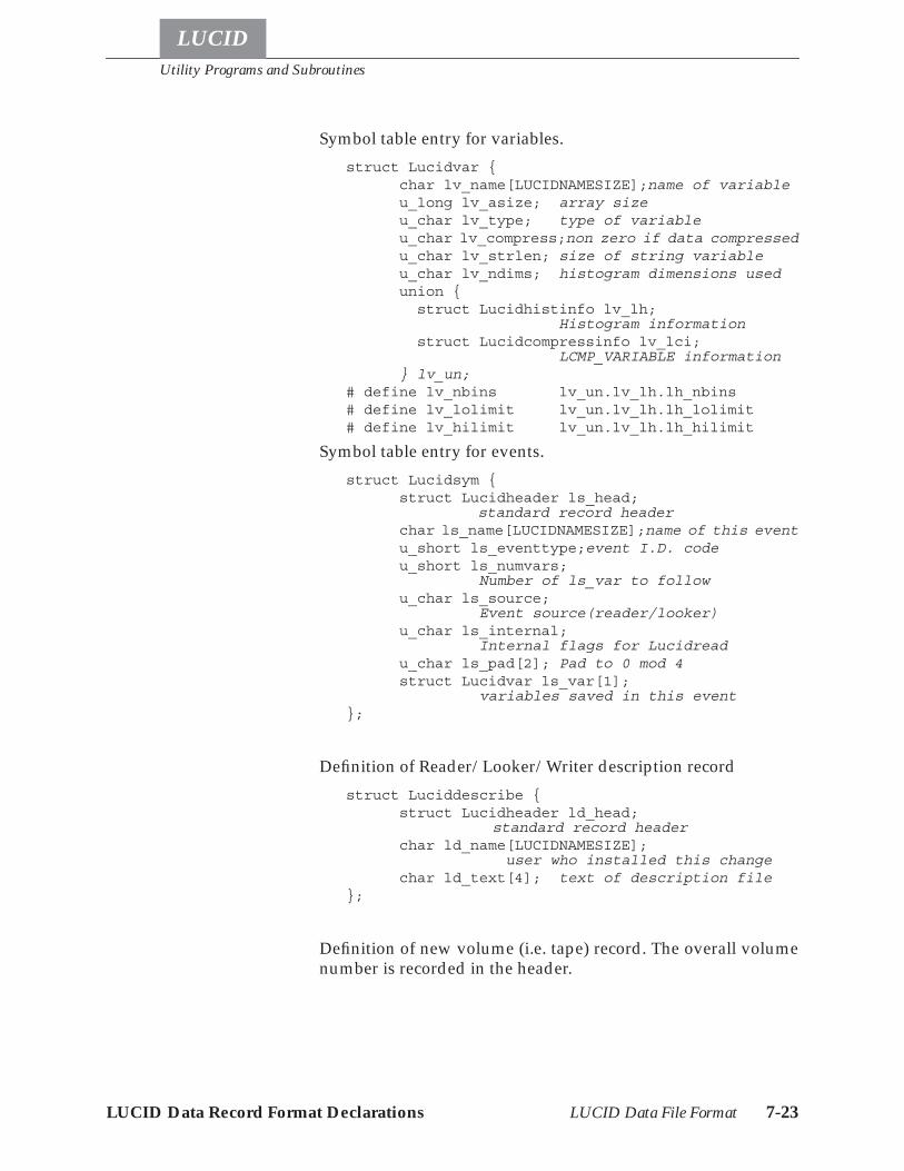
Utility Programs and Subroutines
LUCID Data Record Format Declarations LUCID Data File Format 7-23
LUCID
Symbol table entry for variables.struct Lucidvar {
char lv_name[LUCIDNAMESIZE];name of variableu_long lv_asize; array sizeu_char lv_type; type of variableu_char lv_compress;non zero if data compressedu_char lv_strlen; size of string variableu_char lv_ndims; histogram dimensions usedunion { struct Lucidhistinfo lv_lh;
Histogram information struct Lucidcompressinfo lv_lci;
LCMP_VARIABLE information} lv_un;
# define lv_nbins lv_un.lv_lh.lh_nbins# define lv_lolimit lv_un.lv_lh.lh_lolimit# define lv_hilimit lv_un.lv_lh.lh_hilimit
Symbol table entry for events.struct Lucidsym {
struct Lucidheader ls_head;standard record header
char ls_name[LUCIDNAMESIZE];name of this eventu_short ls_eventtype;event I.D. codeu_short ls_numvars;
Number of ls_var to followu_char ls_source;
Event source(reader/looker)u_char ls_internal;
Internal flags for Lucidreadu_char ls_pad[2]; Pad to 0 mod 4struct Lucidvar ls_var[1];
variables saved in this event};
Definition of Reader/Looker/Writer description recordstruct Luciddescribe {
struct Lucidheader ld_head;standard record header
char ld_name[LUCIDNAMESIZE];user who installed this change
char ld_text[4]; text of description file};
Definition of new volume (i.e. tape) record. The overall volumenumber is recorded in the header.
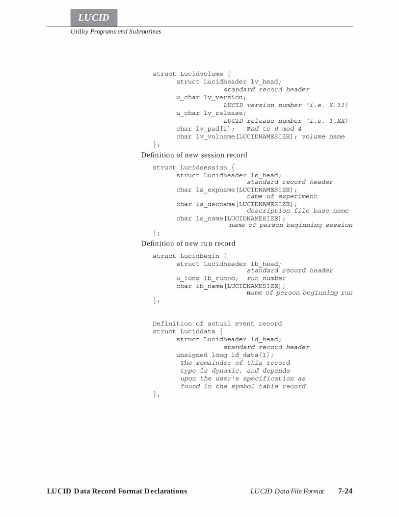
Utility Programs and Subroutines
LUCID Data Record Format Declarations LUCID Data File Format 7-24
LUCID
struct Lucidvolume {struct Lucidheader lv_head;
standard record headeru_char lv_version;
LUCID version number (i.e. X.11)u_char lv_release;
LUCID release number (i.e. 1.XX)char lv_pad[2]; Pad to 0 mod 4char lv_volname[LUCIDNAMESIZE]; volume name
};
Definition of new session recordstruct Lucidsession {
struct Lucidheader ls_head;standard record header
char ls_expname[LUCIDNAMESIZE];name of experiment
char ls_dscname[LUCIDNAMESIZE];description file base name
char ls_name[LUCIDNAMESIZE];name of person beginning session
};
Definition of new run recordstruct Lucidbegin {
struct Lucidheader lb_head;standard record header
u_long lb_runno; run numberchar lb_name[LUCIDNAMESIZE];
name of person beginning run};
Definition of actual event recordstruct Luciddata {
struct Lucidheader ld_head;standard record header
unsigned long ld_data[1];The remainder of this record type is dynamic, and depends upon the user's specification as found in the symbol table record
};
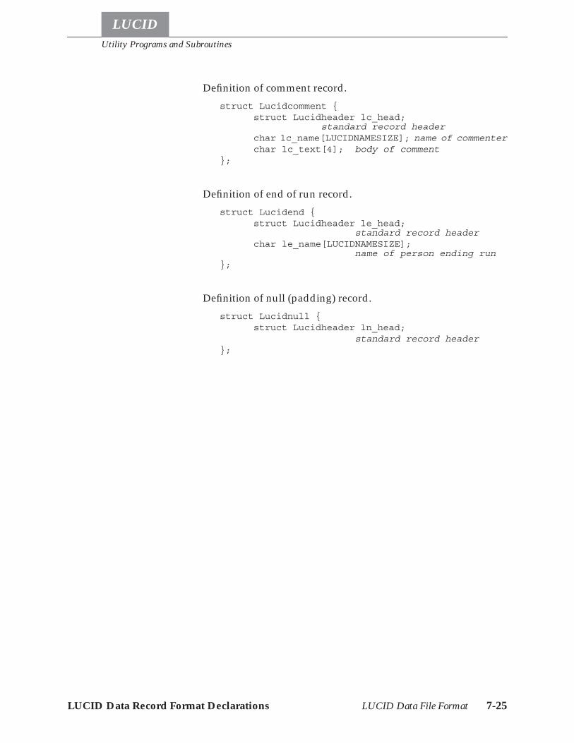
Utility Programs and Subroutines
LUCID Data Record Format Declarations LUCID Data File Format 7-25
LUCID
Definition of comment record.struct Lucidcomment {
struct Lucidheader lc_head;standard record header
char lc_name[LUCIDNAMESIZE]; name of commenterchar lc_text[4]; body of comment
};
Definition of end of run record.struct Lucidend {
struct Lucidheader le_head;standard record header
char le_name[LUCIDNAMESIZE];name of person ending run
};
Definition of null (padding) record.struct Lucidnull {
struct Lucidheader ln_head;standard record header
};

Utility Programs and Subroutines
LUCID Data Record Format Declarations LUCID Data File Format 7-26
LUCID
LUCID
A-1
Appendix
A The CAMAC Module Database
LUCID’s knowledge of CAMAC modules comes from informa-tion stored in a system database file, which doesn’t change veryoften. The file is named "~lucid/lib/camac.modules", and al-though anyone can look through the file, only the system admin-istrator is allowed to change it. Chapter 2 is entitled UsingLUCID, and it describes how you can get LUCID to use your ownmodule definition file, which is nice when you want to test a newmodule, or use an uncommon feature of an existing module.Most users will ask the system administrator to add a definitionto the system database, since there is no practical limit on thenumber of modules that LUCID can know about, and other ex-perimenters will eventually want to use that module.The module definition file contains simple descriptions of CA-MAC modules, which tell LUCID how to access the modules.This includes commands for simple reading and writing, butalso how to enable and disable LAMs, and how to read and clearmodules in a single operation. LUCID "silently" reads this CA-MAC database every time you start it up, so you normally neverneed to know of the file’s existence.
Defining the Modules
Definitions are listed one after another in the database file. Eachdefinition starts with a line containing the word module, fol-lowed by one or more names for that module. For example, thedefinition for a Kinetic Systems model 3615 scaler starts off likethis:
module "Kinetic Systems 3615 6-Input 100 MHz Scaler""scaler3615""ks3615""3615"
Defining the Modules A-2
LUCID
You can have several "aliases" for a CAMAC module, but each ofthem must be surrounded by double quotes. Recall that whenyou specify a type of CAMAC variable in your READER descrip-tion file, the type of variable must match one of the names givenin the database. For instance, our first example under The DE-FINE Section on page 3-4 was:
define doubles "3615" crate 1 slot 10 addr 0-2
LUCID recognizes the module "3615" because it appears as oneof the aliases in the CAMAC database file.The first name for a module should be a long, descriptive one;That’s the name LUCID will display if it thinks you’re using amodule incorrectly in your READER description file. The othernames should be written in decreasing order of length, as shownin the first example. There is no reasonable limit on the numberof aliases you can have for a module.As with all LUCID files, the lines in the CAMAC database are freeformat. The recommended format for the CAMAC database isthat each module line start at the left hand margin, and that allsubsequent lines for that definition are indented by one TABcharacter. This makes it easy to read the definition and find mod-ule names quickly, and it also allows you to print a list of all themodules very easily, using the "grep" command in UNIX. Com-ments are encouraged inside the database file, and are intro-duced by an octothorpe (#) character, except when it is inside acharacter string. All characters from that point to the end of thatline are ignored, as in all other LUCID files. You should also leaveat least one blank line between subsequent CAMAC module def-initions, just to denote the end of one definition and the start ofanother.After all the aliases for a module are given in the file, all of theappropriate CAMAC capabilities should be listed.
CAMAC Capabilities
There are twelve different CAMAC capabilities that LUCID un-derstands, each of which are selected by a unique keyword.These keywords can appear in any order after the name aliases.
Readsize and Writesize
The readsize keyword tells LUCID the maximum number ofdata transfers that this module can accept at one time. In the ex-ample of our 6-input scaler, the statement would be:
readsize 6
Defining the Modules A-3
LUCID
Similarly, the word writesize tells LUCID how much data can bewritten to the module at one time. These read and write sizes areused to check and possibly limit the amount of data transferredto or from a module in a single operation1. With respect to defin-ing a CAMAC variable in a READER description file, this size de-termines the array size of the variable. All modules should havea readsize or writesize defined. An option for "hold mode"transfers can be specified with these keywords; this will be dis-cussed under HOLD Mode Transfers on page A-4.
Shortword and Longword
Most CAMAC modules transfer 16-bit values, or less. However,LUCID must be able to communicate with 24-bit modules aswell, such as high density ECL coincidence registers. The key-words shortword and longword tell LUCID whether the modulewill transfer 16 or 24 bits, respectively. If neither of these key-words is present, LUCID assumes the module will transfer 16bits. Only one of these keywords may be included in one moduledefinition.
Checking Module Identity
Some CAMAC modules have an internal status value whichmight contain a serial number or I.D. number. If a module’s def-inition includes a check statement, then LUCID’s program willcheck that value before it starts the experiment. This is usefulwhen setting up an experiment, because LUCID can help remindyou when modules have been moved around. The general for-mat of this statement is:
check is f1 a1: data & 0140 = 0100
This tells LUCID to use F(1) A(1) to read the status value. It alsotells LUCID that within that piece of data, the sixth and seventhrightmost bits must be zero and one, respectively. Octal (baseeight) values are most commonly used here, since they representbit positions. Decimal values can be used, but should be avoidedto prevent confusion. In the this example, the value 0140 repre-sents 001100000 in binary. The value 0100 represents the binaryvalue of 001000000. The first value tells LUCID which bits are ofinterest, and the second value tells what state those correspond-ing bits should be in. Thus, the sixth rightmost bit must be a zero,and the seventh rightmost bit must be a one.
1. For more information, refer to the last part of the Section entitled Reading Data on page 3-14.
Defining the Modules A-4
LUCID
If this test is performed and the result isn’t what you’ve told LU-CID to expect, then an error message will be displayed when youtry and start the experiment.
Read
All other capabilities in the database file are associated with CA-MAC function codes and sub-address values. The read keywordtells LUCID what function code to use when reading the module,and what sub-address codes (A-codes) are acceptable. When theuser tells LUCID to read this CAMAC variable, it will repeatedlyuse the function code with each of the A-codes to do it. If a sub-script is given for that variable, then only that A-code will beused. In any case, the statement must have the form:
read is f0 a0-5
This tells LUCID to use F(0) with a sub-address code A(0)through A(5). Also, the keyword "is" is optional. If the moduleonly understands one A-code, then the definition would be whatone would expect:
read is f0 a0
LUCID will warn you if it finds a function code for reading whichis not between 0 and 7. It also complains if the A-codes are notbetween 0 and 15.
HOLD Mode Transfers
Certain types of CAMAC modules allow reading or writing sev-eral channels without changing the A-code every time. Theykeep track internally of what has been accessed, and automati-cally proceed to the next "channel" after every transfer. These arecalled hold mode transfers, because the computer holds the sameA-code on every transfer to or from the module. In some cases,hold mode transfers can be performed slightly faster than ordi-nary transfers. More importantly, CAMAC only allows sixteendifferent A-codes to be used, and some modules need to transfermore data than can be done in sixteen transactions.
Defining the Modules A-5
LUCID
With hold mode transfers, a large amount of data can be trans-ferred in a single read statement from LUCID. For instance, awaveform digitizer can transfer an array of 1024 bytes with a sin-gle read statement from the READER. To tell LUCID that a mod-ule uses hold mode reads or writes, you must include the wordhold after the readsize or writesize statements in the database.For instance, an appropriate statement for the previously men-tioned waveform digitizer would be:
readsize 1024 hold
Hold mode can therefore be used when reading or writing.
Write
The write keyword tells LUCID what function code to use whenwriting to this module. The statement is essentially the same asthe read statement, except that LUCID will complain if the func-tion code is not between 16 and 23. The same rules for hold modetransfers also apply. For example:
write is f17 a0-9
Read and Clear
When the user wants to read and clear a module with one oper-ation, LUCID uses the CAMAC operation specified with the read-clear keyword. Normally, the function code is F(2), but LUCIDwarns you if it is not between 0 and 7. The hold mode transfer forreading applies to this operation.
readclear is f2 a0-15
Clear
A simple clear operation may be specified by the user, which isdifferent from the "clear" in a read and clear operation. In thiscase, the entire module is cleared (reset) to it’s initial state. Nor-mally, the command is F(9).
clear is f9 a0
Enabling and Disabling LAMs
LUCID will try to enable LAMs in those modules which useLAMs for triggers. It will also try to disable LAMs from all othermodules. To specify the "enable LAM" command, the statementis:
enable is f26 a0
Defining the Modules A-6
LUCID
LUCID will complain if the function code is not between 24 and31. Similarly, to disable LAMs from a module, the statementlooks like:
disable is f24 a0
Testing for LAM Status
If the user tells LUCID to wait for a module in his READER de-scription file, then LUCID simply waits for a LAM status bit tobecome true, usually because that particular module will notcause an interrupt when a LAM is ready. We often think of LAMsas being the same as interrupts, except a LAM is essentiallysomething that can be tested. An interrupt is a trigger, which isoften caused by a LAM.The test LAM function is recognized by most modules, and thestatement should look like:
testlam is f9 a0
LUCID’s READER program will repeatedly issue the commanduntil the "Q" response from the module is true, meaning that aLAM state exists. This is used only for the wait command fromthe user.
Clearing LAMs
When LUCID has processed an interrupt (LAM) trigger, it willtry and clear the interrupt state, so it can accept a new one. Mod-ules usually respond to an F(10) command to clear the LAMstate. Keep in mind that this is different from the read and clearoperation, and from the clear operation; It simply resets the in-terrupt that has just arrived from the module. The command is:
clearlam is f10 a0-5
Notice that individual channels may interrupt in some modules;Specifying several A-codes will cause LUCID to clear all of them.
Self-Clearing Modules
Certain modules will reset their interrupt state automatically, af-ter the last channel is read out. For instance, the LeCroy model2259 Peak Sensing ADC has twelve inputs, and will issue a LAMwhen it has finished conversion and is ready to be accessed.When the last input has been successfully read out, the module
Defining the Modules A-7
LUCID
clears it’s own LAM; it essentially sends itself and F(10) com-mand. To make use of this feature, you may use the autoclearstatement within the CAMAC module database file. This tells LU-CID not to clear the module if the user causes the last channel tobe read out.
Q-Stop Modules
Some modules make a variable amount of data available at atime, and indicate the end of the data transfer by a change in themodule’s Q state. The keyword qstop indicates this. The eventdata saved from a Q-stop module is automatically compressed,as described in the following section.
Self-compressing Modules
Modules, such as Q-stop modules, that provide a variableamount of data each event are considered self-compressing mod-ules. The CAMAC Module Database provides a good deal offlexibility in defining the format of the data for the two mostcommon cases: a simple list of values, and a list of channel-valuepairs. The statement used for both these cases is
channel length CL offset CO value length VL offset VO
The lengths and offsets of each field are specified as bit positionscounting from the least significant bit. The offset bits are countedstarting with the least significant bit, which has an offset of 0. Alength of 0 indicates the field isn’t used, so a module with ashortword word size and a compression definition of
channel length 0 value length 16 offset 0
would indicate no channel data and a single shortword for thedata value.The READER does not actually use the compression informa-tion provided! Rather, this information is made available to theLOOKER to decode the compression.A more complete discussion of different compression formatscan be found in the section LUCID Data File Format on page7-15.

Sample CAMAC Module Database A-8
LUCID
Sample CAMAC Module Database
The following definitions originate from a CAMAC module da-tabase on an active LUCID system. The modules are in no specif-ic order, but are presented to show how the statements shouldappear in the file. You should consult the user’s manuals for eachof these modules to see how the CAMAC commands are repre-sented here. Remember that modules may be duplicated if theyhave different names, or slightly different functions. If LUCIDfinds duplicate module names, it will use the first name in thefile.
module "Accelerator lab homemade 16-channel ECL D-Flip/Flop Coincidence Module"
"SAL Dffcoin""SAL Dff"shortwordread is f0 a0
module "Accelerator lab homemade 8-channel ECL DelayModule"
"SAL Ecldelay"readsize 8shortwordwrite is f16 a0-7read is f0 a0-7
module "Accelerator lab homemade super tagger unit""SAL supertagger 2""SAL stu"shortwordread is f0 a0clear is f10 a0
module "Accelerator lab homemade tagger triggermodule"
"SAL supertagger""SAL stm"shortwordread is f0 a0clear is f9 a0
module "Accelerator lab homemade output register""SAL outreg""SAL oreg"shortwordread is f0 a0write is f16 a0clear is f9 a0
module "Interface Standards OD/48 48-bit outputregister"
Sample CAMAC Module Database A-9
LUCID
"od/48"readsize 2writesize 2longwordread f0 a0-1write f16 a0-1test is f8 a0clearlam is f10 a0disable is f24 a0enable is f26 a0check is f1 a1: data & 017600 = 02000
module "Jorway model 41 NIM output register""J41""Jorway 41"shortwordwrite f16 a0
module "Kinetic Systems 3615 6-input 100 MHz Scaler""3615""ks3615""ksc3615""Kinetic Systems 3615"readsize 6longwordread is f0 a0-5clear is f9 a0-5readclear is f2 a0-5enable is f26 a0disable is f24 a0testlam is f8 a0-5clearlam is f10 a0-5
module "Kinetic Systems 3924 LAM Encoder for SerialHighway"
"3924""ks3924""ksc3924""Kinetic Systems 3924"readsize 1read is f1 a12enable is f26 a1disable is f24 a1testlam is f8 a0clearlam is f10 a0clear is f10 a0
module "LeCroy Model 2228A/2229 Octal TDC""2228A""2229""LeCroy 2228A""LeCroy 2229"
Sample CAMAC Module Database A-10
LUCID
timeout 100readsize 8shortwordautoclearread is f0 a0-7readclear is f2 a0-7test is f8 a0clear is f9 a0disable is f24 a0enable is f26 a0
module "LeCroy 2248 8-Channel Differential ADC""2248""LeCroy 2248"timeout 106autoclearreadsize 8shortwordread is f0 a0-7readclear f2 a0-7enable f26 a0disable f24 a0testlam f8 a0clearlam f10 a0
module "LeCroy Model 2249A/SG 12 channel ADC""2249A""2249SG""LeCroy 2249A""LeCroy 2249SG"timeout 60autoclearreadsize 12shortwordread is f0 a0-11readclear is f2 a0-11test is f8 a0-11clear is f9 a0disable is f24 a0enable is f26 a0
module "LeCroy Model 2249W/2259B 12 channel ADC""2249W""2259B""LeCroy 2249W""LeCroy 2259B"timeout 106autoclearreadsize 12shortwordread is f0 a0-11readclear is f2 a0-11
Sample CAMAC Module Database A-11
LUCID
test is f8 a0-11clear is f9 a0disable is f24 a0enable is f26 a0
module "LeCroy Model 2256A 20 MHz WaveformDigitizers"
"2256A""LeCroy 2256A"readsize 128 holdshortwordread is f2 a0test is f8 a0clear is f9 a0disable is f24 a0enable is f26 a0
# NOTE: the 2277 can be used to read out multiplevalues for a single# channel. This is not directly usable in the looker.Instead, the# user must decode this manually.# To use automatic decoding, change the'readsize' line to::# readsize 512 qstop channel length 5 offset17 value length 17 offset 0#module "LeCroy Model 2277 32 Channel TDC"
"2277""LeCroy 2277"readsize 512 qstop channel length 0 value
length 22 offset 0longwordread is f0 a0test is f8 a0clear is f9 a0disable is f24 a0enable is f26 a0
module "LeCroy 2323A Dual Gate and Delay Generator""2323A""LeCroy 2323A"readsize 2shortwordread is f1 a0-1clear is f9 a0-1write is f17 a0-1
module "LcCroy Model 2341S 16-fold coincidenceregister/pattern unit"
"2341S""LeCroy 2341S"readsize 1
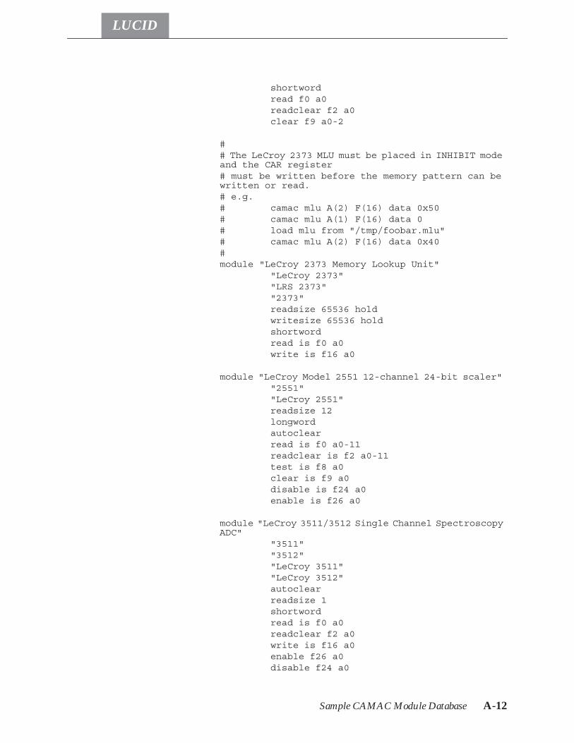
Sample CAMAC Module Database A-12
LUCID
shortwordread f0 a0readclear f2 a0clear f9 a0-2
## The LeCroy 2373 MLU must be placed in INHIBIT modeand the CAR register# must be written before the memory pattern can bewritten or read.# e.g.# camac mlu A(2) F(16) data 0x50# camac mlu A(1) F(16) data 0# load mlu from "/tmp/foobar.mlu"# camac mlu A(2) F(16) data 0x40#module "LeCroy 2373 Memory Lookup Unit"
"LeCroy 2373""LRS 2373""2373"readsize 65536 holdwritesize 65536 holdshortwordread is f0 a0write is f16 a0
module "LeCroy Model 2551 12-channel 24-bit scaler""2551""LeCroy 2551"readsize 12longwordautoclearread is f0 a0-11readclear is f2 a0-11test is f8 a0clear is f9 a0disable is f24 a0enable is f26 a0
module "LeCroy 3511/3512 Single Channel SpectroscopyADC"
"3511""3512""LeCroy 3511""LeCroy 3512"autoclearreadsize 1shortwordread is f0 a0readclear f2 a0write is f16 a0enable f26 a0disable f24 a0
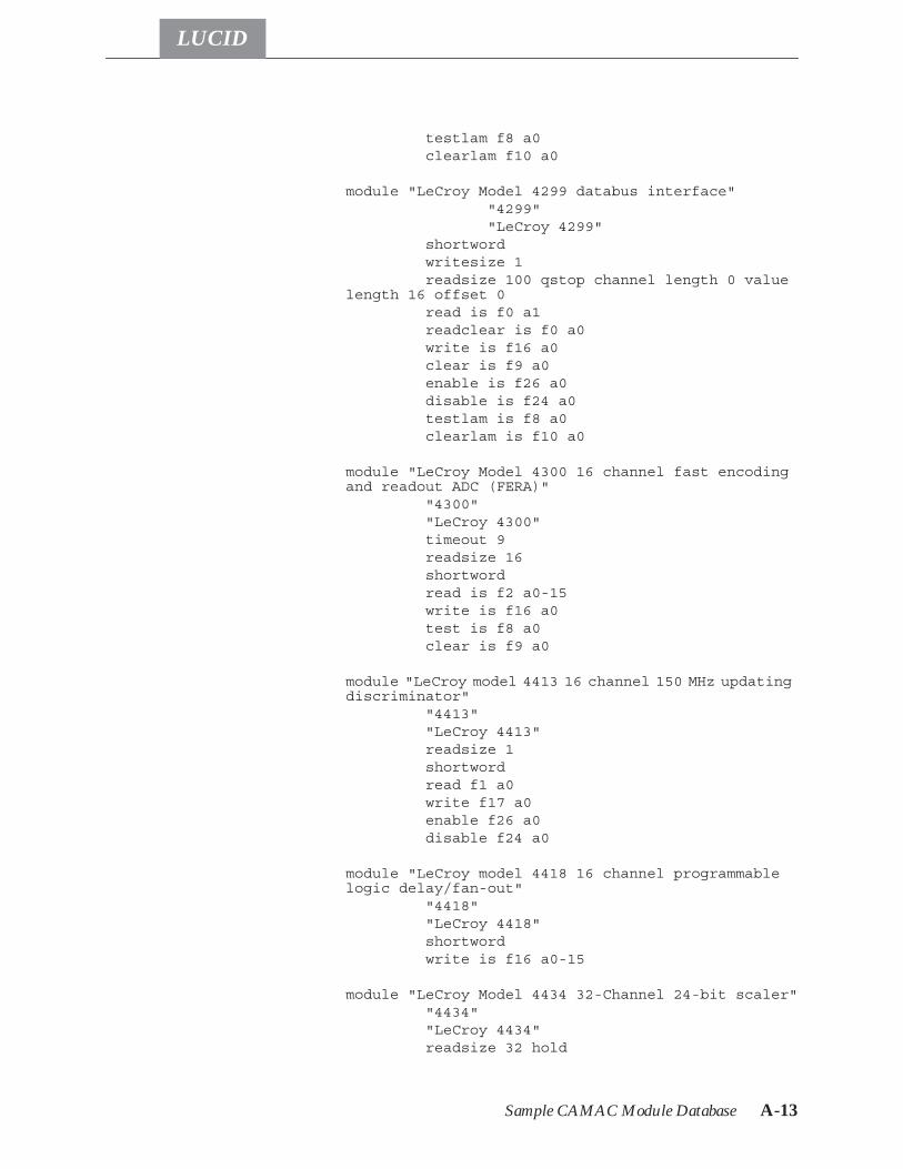
Sample CAMAC Module Database A-13
LUCID
testlam f8 a0clearlam f10 a0
module "LeCroy Model 4299 databus interface" "4299" "LeCroy 4299"
shortwordwritesize 1readsize 100 qstop channel length 0 value
length 16 offset 0read is f0 a1readclear is f0 a0write is f16 a0clear is f9 a0enable is f26 a0disable is f24 a0testlam is f8 a0clearlam is f10 a0
module "LeCroy Model 4300 16 channel fast encodingand readout ADC (FERA)"
"4300""LeCroy 4300"timeout 9readsize 16shortwordread is f2 a0-15write is f16 a0test is f8 a0clear is f9 a0
module "LeCroy model 4413 16 channel 150 MHz updatingdiscriminator"
"4413""LeCroy 4413"readsize 1shortwordread f1 a0write f17 a0enable f26 a0disable f24 a0
module "LeCroy model 4418 16 channel programmablelogic delay/fan-out"
"4418""LeCroy 4418"shortwordwrite is f16 a0-15
module "LeCroy Model 4434 32-Channel 24-bit scaler""4434""LeCroy 4434"readsize 32 hold
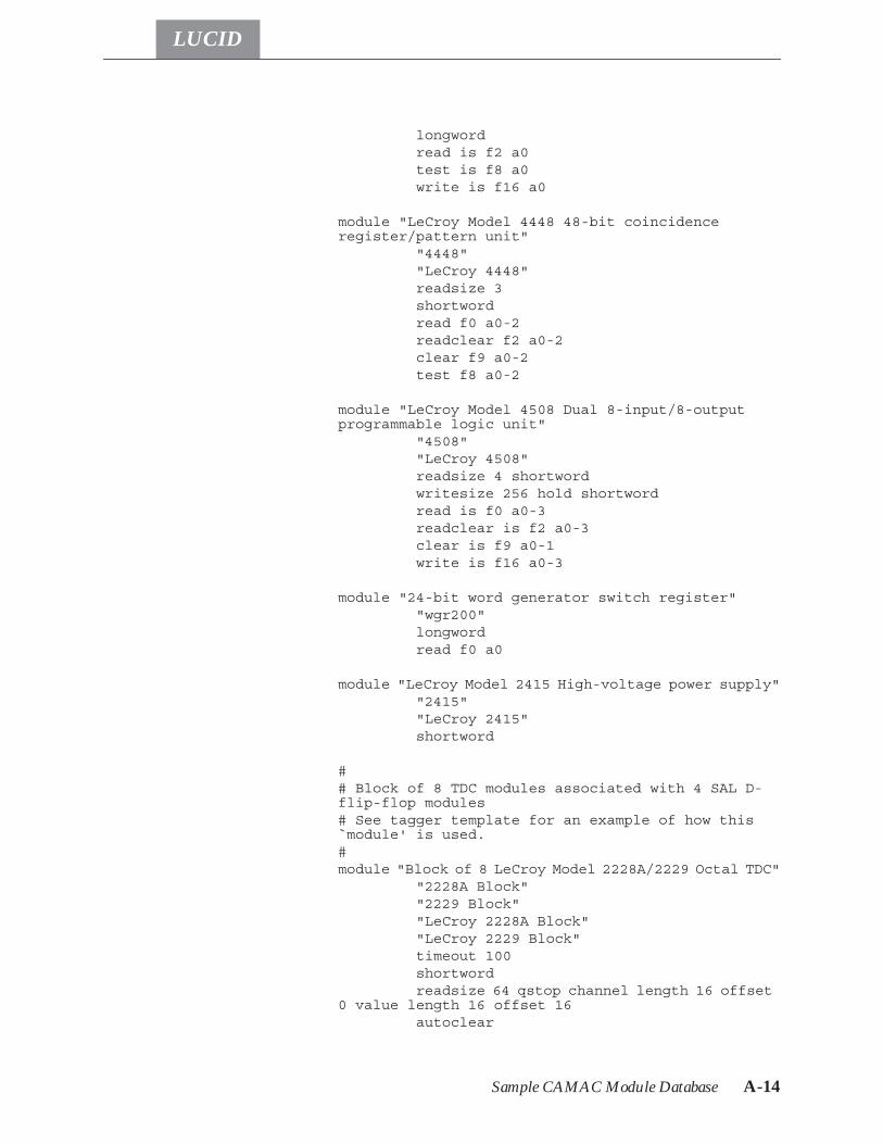
Sample CAMAC Module Database A-14
LUCID
longwordread is f2 a0test is f8 a0write is f16 a0
module "LeCroy Model 4448 48-bit coincidenceregister/pattern unit"
"4448""LeCroy 4448"readsize 3shortwordread f0 a0-2readclear f2 a0-2clear f9 a0-2test f8 a0-2
module "LeCroy Model 4508 Dual 8-input/8-outputprogrammable logic unit"
"4508""LeCroy 4508"readsize 4 shortwordwritesize 256 hold shortwordread is f0 a0-3readclear is f2 a0-3clear is f9 a0-1write is f16 a0-3
module "24-bit word generator switch register""wgr200"longwordread f0 a0
module "LeCroy Model 2415 High-voltage power supply""2415""LeCroy 2415"shortword
## Block of 8 TDC modules associated with 4 SAL D-flip-flop modules# See tagger template for an example of how this`module' is used.#module "Block of 8 LeCroy Model 2228A/2229 Octal TDC"
"2228A Block""2229 Block""LeCroy 2228A Block""LeCroy 2229 Block"timeout 100shortwordreadsize 64 qstop channel length 16 offset
0 value length 16 offset 16autoclear
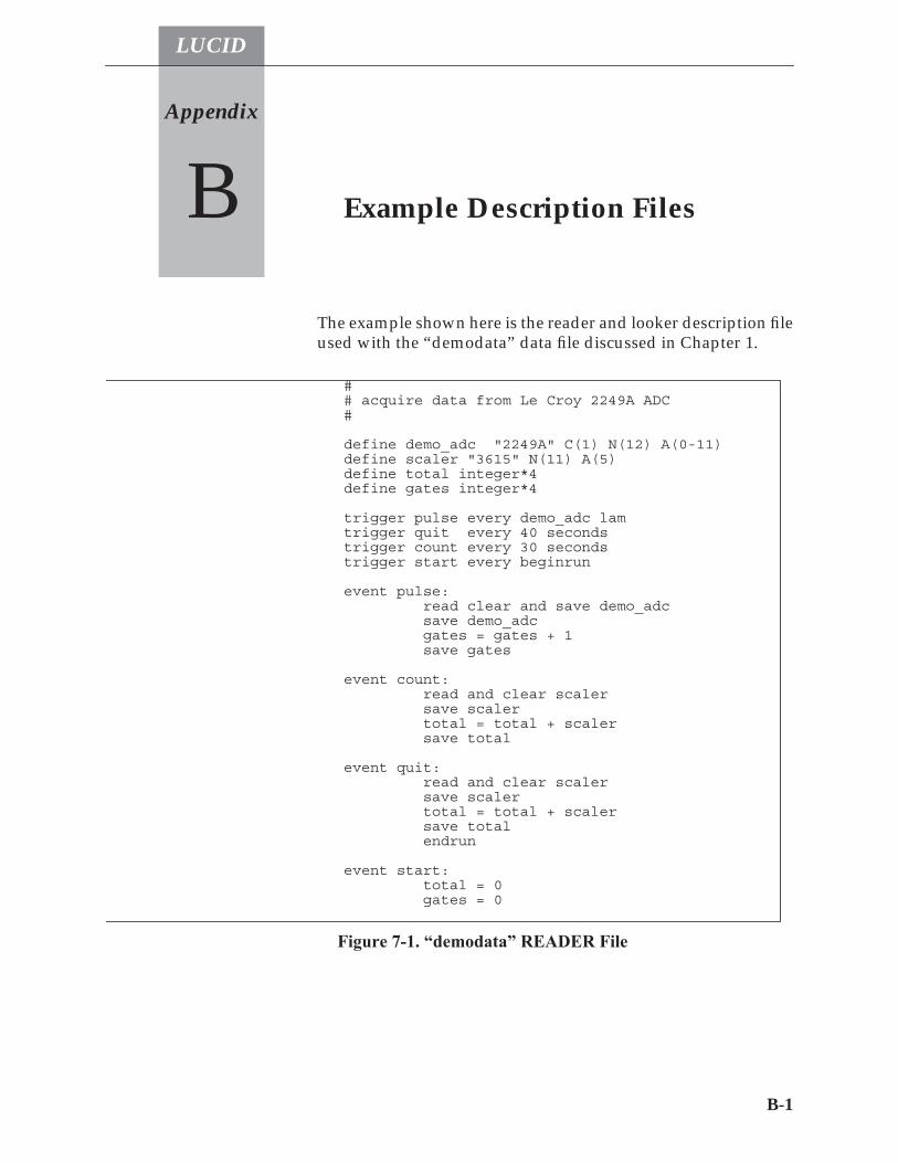
LUCID
B-1
Appendix
B Example Description Files
The example shown here is the reader and looker description fileused with the “demodata” data file discussed in Chapter 1.
## acquire data from Le Croy 2249A ADC#
define demo_adc "2249A" C(1) N(12) A(0-11)define scaler "3615" N(11) A(5)define total integer*4define gates integer*4
trigger pulse every demo_adc lamtrigger quit every 40 secondstrigger count every 30 secondstrigger start every beginrun
event pulse:read clear and save demo_adcsave demo_adcgates = gates + 1save gates
event count:read and clear scalersave scalertotal = total + scalersave total
event quit:read and clear scalersave scalertotal = total + scalersave totalendrun
event start:total = 0gates = 0
Figure 7-1. “demodata” READER File
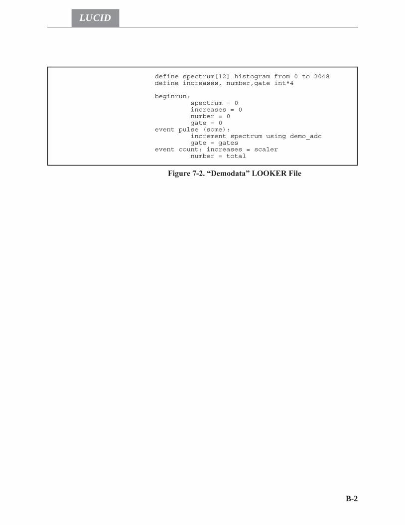
B-2
LUCID
define spectrum[12] histogram from 0 to 2048define increases, number,gate int*4
beginrun:spectrum = 0increases = 0number = 0gate = 0
event pulse (some):increment spectrum using demo_adcgate = gates
event count: increases = scalernumber = total
Figure 7-2. “Demodata” LOOKER File
LUCID
C-1
Appendix
C Known Problems
Like many other things today, LUCID is good, but not perfect.The first concern of any user of any software package is, “Whatdoesn’t work quite as documented?” The second concern is,“Will you add this feature?” The following sections try and ad-dress these concerns by documenting known problems as com-pletely as possible, and by listing the requested enhancementsthat are most likely to added.
Known Bugs
• The C unary operator “!” is not supported as a condition-al operator.
• Use of XLUCID properties causes difficulties when mov-ing from one experiment to the next.
• The luciddraw utility program, when used at the sametime as the XLUCID program, can lock up the experi-ment.
• XLUCID will allow you to change directory for workingwith different reader/looker files, but does not changethe directory for the LUCID program. Changes made tothe program files are not seen until XLUCID is restartedin the new directory.
• Shutting down an experiment completely from XLUCIDdoes not always kill the manager process.
• The XLUCID message window can overflow.
Problems When Running Off-Line.
• Starting an existing off-line experiment on a new machinedoes not automatically find and copy the list of users whocan access the experiment.
• When reading multiple run number ranges, pressing stopthen rewind can hang XLUCID.
Requested Enhancements C-2
LUCID
Problems When Running On-Line
• Stopping LUCID from a paused state does not give theuser the option of Just Stop or Resume then Stop.
• SunOS does not always add an EOT when a tape deviceis closed. LUCID on-line data tapes will report an errorafter reading all the data, although the data and the gen-erated histograms are fine.
Requested Enhancements
As you read this section, remember that these are only the re-quested enhancements that are most likely to be implemented.Although many of these changes will be done, and some are al-ready being scheduled, there is no guarantee that all will be add-ed.
Changes to READER
• Add Loops statements for the experiment reader file.
Changes to WRITER
• No known requests outstanding.
Changes to LOOKER
• Allow on-line data acquisition to continue while a lookeris being rebuilt.
• Off-line lookers could optionally close the data stream atthe end of the last requested run.
• increment statements should have the option to incre-ment by a value other than 1 or -1.
• Processing of some or all events should be switchable out-side the looker description file.
• The print statement should allow some type of formattingoption.
• Add two-dimensional arrays. • Allow “non-fatal” read errors: processing would contin-
ue at the beginning of the next run.
Requested Enhancements C-3
LUCID
Changes to XLUCID
• Add saving of histogram data directly to a user program. • Add log scale display on axes. • Add “bytes seen this run” information when forwarding
over data. • Add a routine callable by user subroutines that accesses
data in a lucid data structure. • Add backspacing of LUCID tapes to the beginning of a
session. • Add other information onto histograms for printouts
(e.g. date, run number). • Complete the implementation of the Density Plot win-
dow. • Add the ability to modify histogram data that can be re-
turned to the looker. • Implement the Print menu selection. • Implement the Layout menu selection. • Add simple histogram editing resulting in local variables. • Add more statistical functions for histograms (e.g. first
and second moments).

Requested Enhancements C-4
LUCID
LUCID
D-1
Appendix
D Histogram Save File Format
The original format used by LUCID for saved histograms wasextremely simple. It was assumed that histograms saved by theLOOKER would be re-read by the LOOKER, and histogramssaved by XLUCID would be re-read by XLUCID. The new for-mat makes the histogram files consistent, and provides the userwith better information about the histogram saved.
Overview
The histogram file format constists of a header and data body foreach histogram, allowing multiple histograms to be saved in thesame file.
Header
The histogram header consists of one or more lines of free-for-mat information. The different header fields consist of a key-word, possibly followed by a list of parameters. The number ofparameters is fixed for each keyword.Variable Has a single parameter, which is the name of the
variable that was saved.saved Followed by two parameters, which are the date
and time the histogram was saved.run The single parameter is the run number when the
variable was saved.compress No parameters; this indicates that fields that are
zero have not been saved to the file.array This indicates that the histogram is an array, and has
the lower and upper bounds of the array as its twoparameters.
entry entry indicates that this is just one element from ahistogram array, the single parameter tells which el-ement.
Overview D-2
LUCID
Histogram Verifies that the variable saved was a histogram.type The variable type saved; the single parameter is
short, long, float, double or string.X Indicates that the following from, to, and bins key-
words apply to the X axis.Y Indicates that the following from, to, and bins key-
words apply to tye Y axis.from A single parameter, which is the lower limit of val-
ues saved to this histogram.to A single parameter, which is the upper limit of val-
ues saved to this histogram.bins A single parameter, which is the number of bins for
the current axis.byvalue No parameter; byvalue indicates that data is saved as
an X or Y value representative of the bin informa-tion being written out.
midpoint No parameters; this indicates that the X and Y val-ues written out are at the midpoint of the bin. Thedefault is that values are printed as of the lowestedge of the bin.
bybin No parameter; opposite of byvalue.binary No parameter; indicates data is in binary instead of
ascii. This allows smaller data files, but is not alwaysportable to another computer and is diffucult to ma-nipulate with anything but a dedicated program.
ascii No parameter; opposite of binary.
Body
The body of the histogram file varies greatly depending uponthe way the histogram was saved. However, the header informa-tion is sufficient to allow determining which format the data isin.Ascii files have the data from one bin on each line. There can beup to four fields in each line, which are:
array-index x-bin-number y-bin-number value
The array-index only appears if the array keyword is in the head-er. The x-bin-number is present for all histograms, although itcould be a bin number, the x value representing the lowest edgeof the bin, or the x value at the midpoint of the bin, dependingagain on keywords (bybin, byvalue, midpoint). The y-bin-number
Overview D-3
LUCID
is only present for scatter plots (2-dimensional histograms), and,as the x-bin-number, the keywords bybin, byvalue and midpointdetermine if it is a bin number, the y value representing the low-est edge of the bin, or the y value at the midpoint of the bin. Thevalue field is always present, and is the count for the current bin.Histograms that are saved as binary have the same fields as asciisaves under the same circumstances, with the major differencethat the array index, x bin number, and y bin number are allsaved as float values (real*4), and the value field is saved accord-ing to the type of histogram, which is usually long (int*4).

Overview D-4
LUCID
LUCID
INDEX
Index - 1
Aaddclient 7-1Adjust View sub-window 2-27BBuilding an experiment 1-7Built-in Looker variables 4-12CCalculations
on Looker Variables 4-13on Reader Variables 3-23
CAMACClearing modules 3-19Crate Operations from Reader 3-28Crate uninhibit from Reader 3-29Hardware Layout 3-1Loading file data 3-27Module polling 3-20Modules Database 3-5Operations from Reader 3-28Polling modules 3-20Read and Clear Operation 3-19Reading variables 3-17Saving Data 3-18Setting inhibit from Reader 3-29Using LAM’s in Reader 3-2Writing from Reader 3-26
Coding user routinesReader 3-29
Command Line Options 2-4Compressed Data (Reader) 3-21Constants
in Reader 3-13Control buttons - Xlucid 2-19COPYRIGHT NOTICE 1copyrun 7-1DDefault Experiment Directory 2-16Defining functions
Looker 4-6Defining variables
Looker 4-4Reader 3-6
demolucid 7-2Density Map (Xlucid) 2-44Description files
Looker 4-2Reader 3-2
Display Options (Xlucid) 2-29EEject button 2-22Event Rejection in Reader 3-26Event Section
in Looker 4-8in Reader 3-12Some events in Looker 4-10
Experiment Name property 2-16extractrun 7-2Ffindeot 7-2Forward button 2-22Function defines
Looker 4-6Functions
awd(), dwa() 7-10LF_open(), LF_event() 7-11LLucidopen(), Lucidread() 7-10Lucidwopen(), Lucidwrite() 7-11NetCamac() 7-12NetHv...() 7-13Qread() 7-14Qwrite() 7-14User Functions in Looker 4-25User Functions in Reader 3-11
Ggenerate 7-2HHardware Database File Property 2-16Histogram
2D in Looker 4-36Acceptance tests (Looker) 4-21
LUCID
Index
Index - 2
Arrays in Looker 4-28, 4-29Bit histogramming in Looker 4-40Counts per bin 4-29Definition in Looker 4-28Density Map 2-44Edit Data 2-44in Looker 4-26Incrementing in Looker 4-16, 4-33Looker Arrays 4-28, 4-29Print menu button 2-46Region
Save Region 2-45Regions in Looker 4-18Save Region 2-45Send Region 2-45Sub-views (Xlucid) 2-28
Histogram 2D markers 2-32Histogram Autoscaling 2-30Histogram Bins
in Looker 4-28Histogram definitions
in Looker 4-28Histogram Display Bin Numbers 2-30Histogram Display Options 2-29Histogram Grid Lines 2-30Histogram Markers
2D 2-32Adjusting 2-32description 2-27
Histogram menu buttons 2-23Histogram Modes
Pan 2-42Region 2-37Scale 2-39Scale (temporary) 2-43Title 2-44Window 2-44Zoom 2-41Zoom (temporary) 2-43
Histogram Modes (temporary) 2-43Histogram Rebinning (Xlucid) 2-31Histogram Shortcut Keys
Autoscale (a) 2-32Bin Numbers(b) 2-32Delete (DEL) 2-34
Grid Lines (g) 2-33Insert (INS) 2-34Mode 2-34Statistical Information (S) 2-33Stepsize (0-9) 2-33Updating (u) 2-33
Histogram Statistical Data 2-30Histogram View menu button 2-27Histogram Windows 2-23Histogram Zoom buttons 2-30Histogram Zoom By Percentages 2-30hv1440 7-3hv4032 7-3Iintape 7-3KKeyboard Triggers (Reader) 3-10Keywords
increment (Looker) 4-17Looker - see Looker KeywordsReader - see Reader Keywords
LLimits
Acquisition Rate 2-1Event Size 2-1Event Types 2-1
Looker2D histograms 4-362D regions 4-39Array assignment 4-15Arrays 4-6Arrays of histograms 4-28, 4-29Arrays of regions 4-35Assignment 4-13Assignment operators 4-16Bit histogramming 4-40Built-in variables 4-12Call statement 4-25Character Strings 4-16Character Variables 4-16Character variables 4-16Comparison operators 4-21Defining functions 4-6Defining Histograms 4-28
LUCID
Index
Index - 3
Defining regions 4-33, 4-34Defining variables 4-4Description files 4-2Event Section 4-8
Processing some events 4-10Function defines 4-6Groups 4-7Histogram acceptance tests 4-21Histogram arrays 4-28, 4-29Histogram Bins 4-28Histogram definitions 4-28Histogram regions 4-33Histograms 4-26Histrogramming Bits 4-40Incrementing Histograms 4-33Incrementing histograms 4-16Keywords
beginrun 4-11bit 4-40call 4-25command 4-11contains 4-22decrement 4-17endrun 4-11if-then-else 4-21increment 4-17LUCIDbytes 4-13LUCIDonline 4-13LUCIDrun 4-13LUCIDsequence 4-13LUCIDtime 4-13notregion 4-19print 4-24region 4-18repeat 4-23
Keywords List 4-41Operators 4-14Printing values 4-24Regions 4-33
2 dimensional 4-39Arrays 4-35Definition 4-33, 4-34Restrictions 4-36use with histograms 4-18
Repeat statement 4-23
Subroutines 4-25Summation operator 4-14User-specified commands 4-11Variable array 4-6Variable assignment 4-13Variable groups 4-7Variable types 4-3Variable use 4-12
lucid 7-3LUCID - definition 1-1lucid command 7-8LUCID File Format 7-15lucid library 7-10lucidlog 7-3lucidman 7-4lucidview 7-4MMarkers
Description 2-27Modes (Adjust View) 2-28Modules
Use Hardware Database option 2-11Nnetcamac 7-5nethv 7-5OOperators
In Looker statements 4-14In Reader statements 3-23
PPause button 2-21Playback Sequence button 2-20Printing
From Reader 3-24Properties menu 2-15Properties window 2-16QQuit button - Xlucid 2-18qview 7-7RReader
"read and clear" statement 3-19"save data" statement 3-18Arrays 3-24
LUCID
Index
Index - 4
Calculations and Variables 3-23Calling Programs with Arguments 3-16CAMAC
see CAMACcamac keyword 3-28CAMAC Modules Database 3-5clear keyword 3-19Comments in Description File 3-4compress keyword (Reader) 3-22Compressed Array Data 3-21Continuous Triggers 3-10dataway keyword 3-29DEFINE Section 3-4Defining CAMAC Variables 3-4Defining Variables 3-6Description File 3-2elif keyword 3-25else keyword 3-25endif keyword 3-25endrun keyword 3-30event keyword 3-12EVENT section 3-12if keyword 3-25Keyboard triggers 3-10Keywords
"save data" statement 3-18Arithmetic operators 3-23camac 3-28clear 3-19compress 3-22constants 3-13dataway 3-29discard 3-22elif 3-25else 3-25endif 3-25endrun 3-30event 3-12if 3-25load 3-11, 3-27Operators 3-23print 3-24program 3-11read 3-14, 3-17reject 3-26
save 3-18suspendrun 3-30wait 3-20write 3-26
List of Keywords 3-31load keyword 3-11, 3-27Making a description file 3-2Module Timeouts 3-6print keyword 3-24Printing Messages 3-24Program Calling 3-16program keyword 3-11Read and Clear Operation 3-19read keyword 3-14, 3-17Reading CAMAC variables 3-17Reading File Data 3-15Reading program output 3-16Reading User Data 3-14
Arrays 3-15reject keyword 3-26Rejecting an Event 3-26save keyword 3-18Saving CAMAC Data 3-18Sections of a Description File 3-3Software Triggers 3-9Stopping an Experiment 3-30Suspending and Experiment 3-30suspendrun keyword 3-30Trigger Examples 3-11Trigger Polling 3-10Trigger Section 3-8Trigger Statement 3-9trigger statement 3-25Trigger Types 3-8Triggering another Event 3-26User Code 3-29User Code Section 3-11Using Variables in Events 3-12Variable Arrays 3-24Variable Calculations 3-23wait keyword 3-20write keyword 3-26
Reading CAMAC variables 3-17Reading File Data (Reader) 3-15Reading Xlucid Histograms 2-26
LUCID
Index
Index - 5
readsara 7-7Regions
1D in Xlucid 2-372D definitions in Looker 4-392D in Xlucid 2-38Arrays in Looker 4-35Defining in Looker 4-33Definition in Looker 4-34Get Region (Xlucid) 2-44in Looker 4-33Looker definition 4-33, 4-34Looker restrictions 4-36Save Region (Xlucid) 2-45Send Region (Xlucid) 2-45
Rejecting Events in Reader 3-26Rewind button 2-21SSaving CAMAC Data 3-18Saving Xlucid Histograms 2-24Software triggers 3-25Software Triggers (Reader) 3-9Starting an experiment 1-4Status buttons 2-22Stop button 2-21TThe Pause Button 2-21The Rewind Button 2-21The Stop Button 2-21Trigger
definition 2-2Examples (Reader) 3-11
Trigger Section (Reader) 3-8Trigger statement 3-9, 3-25Trigger types 3-8Triggers
Continuous (Reader) 3-10Polling 3-10Software Triggers in Reader 3-26
Triggers from Keyboard (Reader) 3-10Triggers in Software (Reader) 3-9Tutorial Session 1-2UUser Code in Reader 3-11, 3-29User Permissions 2-18
User Permissions window 2-16VVariable types
Looker 4-3Variables
Array assignment in Looker 4-15Arrays in Looker 4-6Assignment in Looker 4-13Assignment operators in Looker 4-16Built-in Looker variables 4-12Calculations in Looker 4-13Calculations in Reader 3-23Character variables in Looker 4-16Defining in Reader 3-6Groups in Looker 4-7Looker groups 4-7Use in Looker 4-12Using variables (Reader) 3-12
View Data window 2-14View Menu (Xlucid) 2-14View menu button - histogram 2-27View Messages window 2-15vme_console 7-7XXlucid
1D Regions 2-372D Regions 2-38Adjust View Stepsize 2-30Adjust View sub-window 2-27Adjusting histogram markers 2-32Change Input File 2-13Control buttons 2-19Control Menu 2-12Eject button 2-22Forward button 2-22Histogram
Density Map 2-44Edit Data 2-44Get Region 2-44Print menu button 2-46Save Region 2-45Send Region 2-45
Histogram 2D markers 2-32Histogram Autoscaling 2-30Histogram Display Bin Numbers 2-30
LUCID
Index
Index - 6
Histogram Display Options 2-29Histogram Grid Lines 2-30Histogram Markers - description 2-27Histogram menu buttons 2-23Histogram Modes
Marker 2-34Pan 2-42Pan (temporary) 2-43Region 2-37Scale 2-39Scale (temporary) 2-43Title 2-44Window 2-44Zoom 2-41Zoom (temporary) 2-43
Histogram Rebinning 2-31Histogram Shortcut Keys
Autoscale (a) 2-32Bin Numbers (b) 2-32Delete (DEL) 2-34Grid Lines (g) 2-33Insert (INS) 2-34Mode 2-34Statistical Information (S) 2-33Stepsize (0-9) 2-33Updating (u) 2-33
Histogram Statistical Data 2-30Histogram Sub-views 2-28Histogram View menu button 2-27Histogram Windows 2-23Histogram Zoom buttons 2-30Histogram Zoom By Percentages 2-30Marker Mode 2-34Modes 2-28Pause button 2-21Playback Sequence button 2-20Properties menu 2-15Properties window 2-16Quit button 2-18Reading Histograms 2-26Regions
1D 2-372D 2-38Get Region 2-44
Rewind button 2-21
Save Histogram 2-24Splitting Histograms 2-28Status buttons 2-22Stepsize 2-30Stepsize (Adjust View) 2-30Stop button 2-21Supply Input 2-14User Commands 2-13User Permissions 2-18User Permissions window 2-16View Data window 2-14View Menu 2-14View Messages window 2-15