Lubrication system for an automobile
38
Engine Lubrication System
-
Upload
sgrsoni45 -
Category
Automotive
-
view
2.868 -
download
1
Transcript of Lubrication system for an automobile

Engine Lubrication System

Purpose of Lubrication System
•Lubricate
Reduces Friction by creating a thin film(Clearance) between moving parts
•Seals
The oil helps form a seal between piston rings and cylinder walls (Reduces Blow-By)
Internal oil leak (blow-by) will result in BLUE SMOKE at the tail pipe.

Purpose of Lubrication System
•Cleans
As it circulates through the engine, the oil picks up metal particles and carbon, and brings them back down to the pan.
•Cools
Picks up heat when moving through the engine and then drops into the cooler oil pan, giving up some of this heat.

Purpose of Lubrication System
•Absorbs shock
When heavy loads are imposed on the bearings, the oil helps to cushion the load.
•Absorbs Contaminants
The additives in oil helps in absorbing the contaminants that enter the lubrication system.
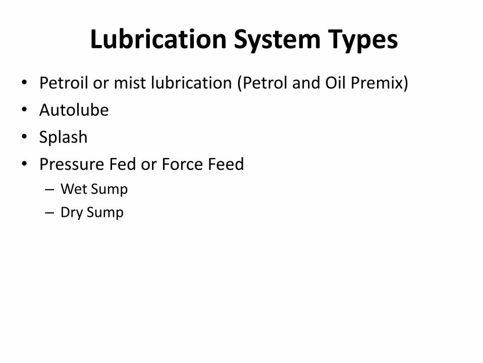
Lubrication System Types
• Petroil or mist lubrication (Petrol and Oil Premix)
• Autolube
• Splash
• Pressure Fed or Force Feed
– Wet Sump
– Dry Sump

Used where crankcase lubrication is not suitable. (In two stroke engine, as the charge is compressed in the crankcase, it is not possible to have the lubrication oil in the sump. Hence mist lubrication is used in practice).
Mist lubrication system

The lubrication oil is mixed with the fuel, the usual ratio being 2% to 5%. Oil and fuel mixture is inducted through the carburetor. Fuel is vaporized and the oil in the form of mist goes via the crankcase into the cylinder. The oil which strikes the crankcase walls lubricates the main and connecting rod bearings and the rest of oil lubricate the piston, piston rings and the cylinder.
Mist lubrication system

Advantages
•Simplicity
•Low cost as it does not require an oil pump, filter, etc.

Disadvantages
•Cause heavy exhaust smoke due to burning of lubricating oil
•Forms deposit on piston crown and exhaust port which affect engine efficiency.
•Requires a thorough mixing for effective lubrication. This requires either separate mixing prior to use or use of some additive to give the oil good mixing characteristics.
•During closed throttle operation (as in the case of vehicle moving down the hill), the engine suffers from insufficient lubrication as the supply of fuel is less. This is an important limitation of system

Autolube System
•Used in 2 stroke engines
•Oil is stored in a separate tank
•A nozzle sprays measured quantity of oil in the crankcase in every stroke
•More efficient than mist lubrication system
•Used in Kinetic Honda, Yamaha RX 100
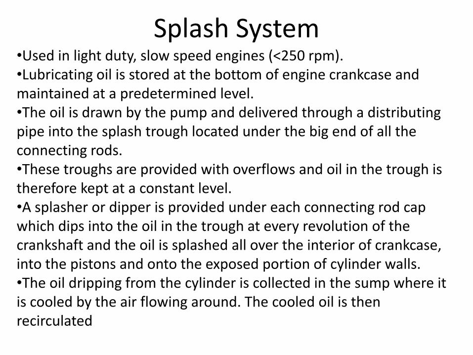
Splash System •Used in light duty, slow speed engines (<250 rpm). •Lubricating oil is stored at the bottom of engine crankcase and maintained at a predetermined level. •The oil is drawn by the pump and delivered through a distributing pipe into the splash trough located under the big end of all the connecting rods. •These troughs are provided with overflows and oil in the trough is therefore kept at a constant level. •A splasher or dipper is provided under each connecting rod cap which dips into the oil in the trough at every revolution of the crankshaft and the oil is splashed all over the interior of crankcase, into the pistons and onto the exposed portion of cylinder walls. •The oil dripping from the cylinder is collected in the sump where it is cooled by the air flowing around. The cooled oil is then recirculated

Splash System
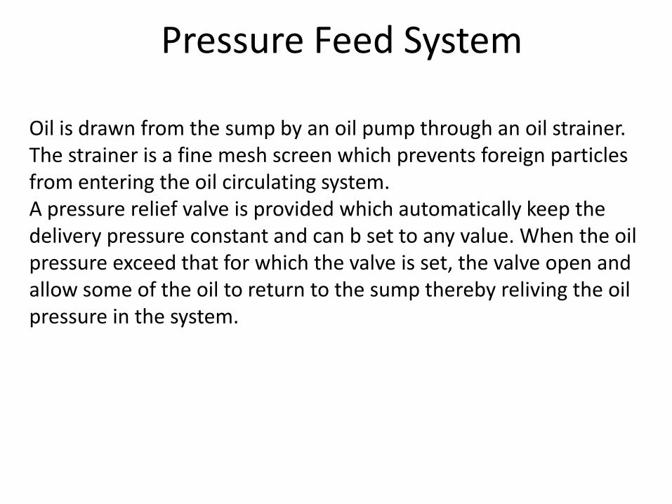
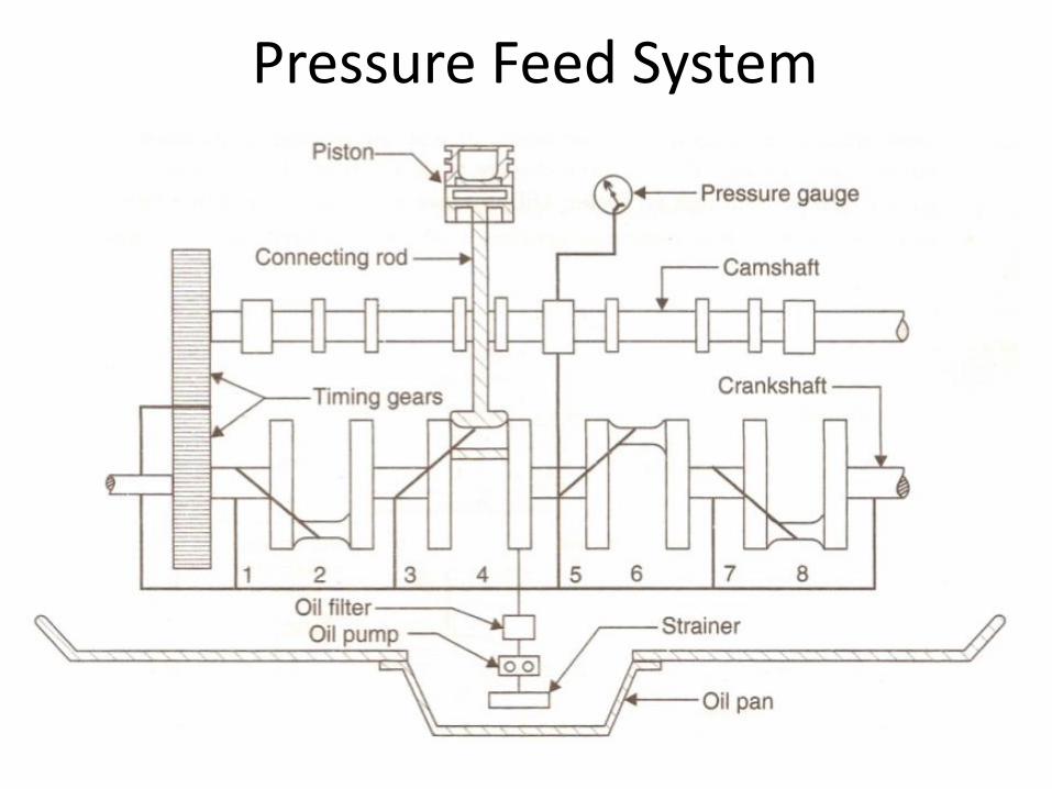
Pressure Feed System
Oil is drawn from the sump by an oil pump through an oil strainer. The strainer is a fine mesh screen which prevents foreign particles from entering the oil circulating system. A pressure relief valve is provided which automatically keep the delivery pressure constant and can b set to any value. When the oil pressure exceed that for which the valve is set, the valve open and allow some of the oil to return to the sump thereby reliving the oil pressure in the system.

Pressure Feed System
Pressure Feed System

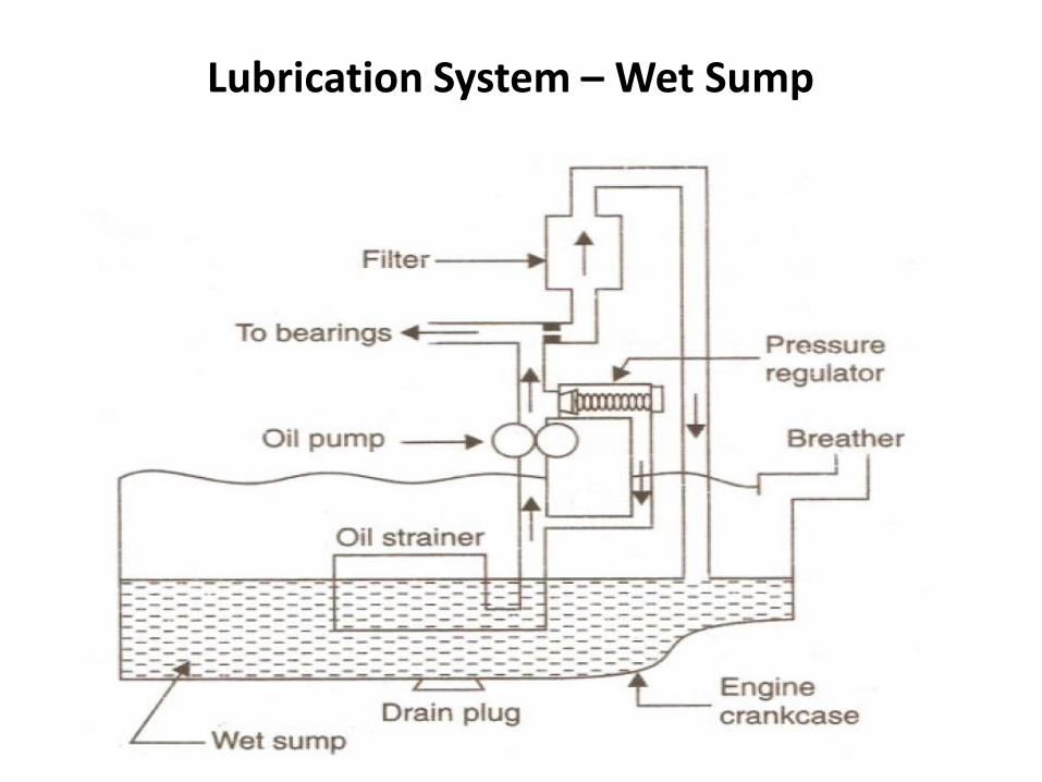
Lubrication System – Wet Sump
Oil is stored in the sump.
Drawn into engine through the pickup.
Forced round by a pump.
Protected by a pressure relief valve.
Carried around in galleries.
Particulates removed by a filter.
Lubrication System – Wet Sump

Dry Sump
It is used in situations when a wet sump cannot cope with the oil supply, in unusual or extreme conditions; Heavy acceleration (racing cars), Off road driving, steep hills and uneven surfaces
It uses an additional pump as well as a remote oil tank

Front
Bearing
Support
Rear
Bearing
Support
Bearing
Support
Bearing
Support
Bearing
Support
No 1
Piston
1
No 2
Piston
2
No 3
Piston
3
No 4
Piston
4
CRANKSHAFT of a 4
CYLINDER ENGINE


22
Lubricating System Parts
• Oil sump
• Oil pump
• Pick-up screen
• Pressure regulator
• Oil filter
• By-pass valve
• Oil galleries
• Dipstick
• Pressure indicator
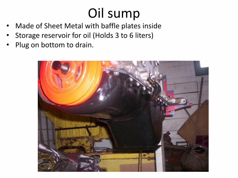
Oil sump • Made of Sheet Metal with baffle plates inside • Storage reservoir for oil (Holds 3 to 6 liters) • Plug on bottom to drain.

Oil Pump Driven by camshaft, crankshaft All types of oil pumps use a pick-up screen in the sump and a pressure regulator.
•Rotor Pump(Two star shaped rotors pump the oil)
•Gear Pump

Rotary Oil Pump
May be shaft, gear or chain driven.
Inner rotor driven by pump shaft.
Inner rotor drives outer rotor.
Oil is forced from input to output
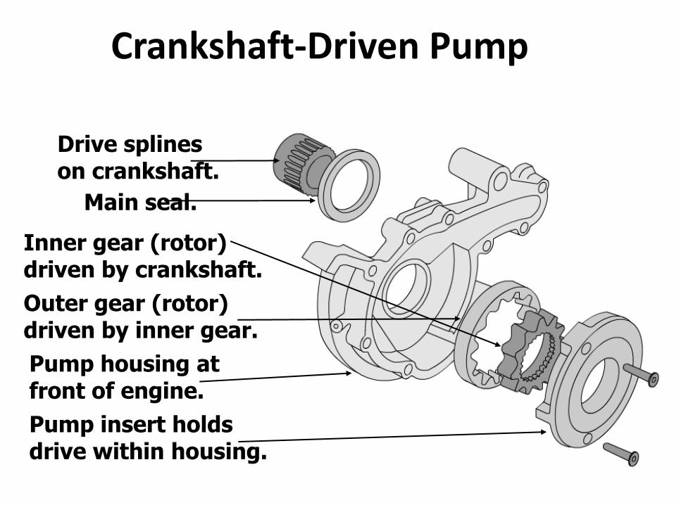
Crankshaft-Driven Pump
Drive splines on crankshaft.
Outer gear (rotor) driven by inner gear.
Inner gear (rotor) driven by crankshaft.
Pump housing at front of engine.
Pump insert holds drive within housing.
Main seal.

Gear Pump
Pump shaft drives one gear.
Other gear rotates.
Low pressure at input.
High pressure at output.
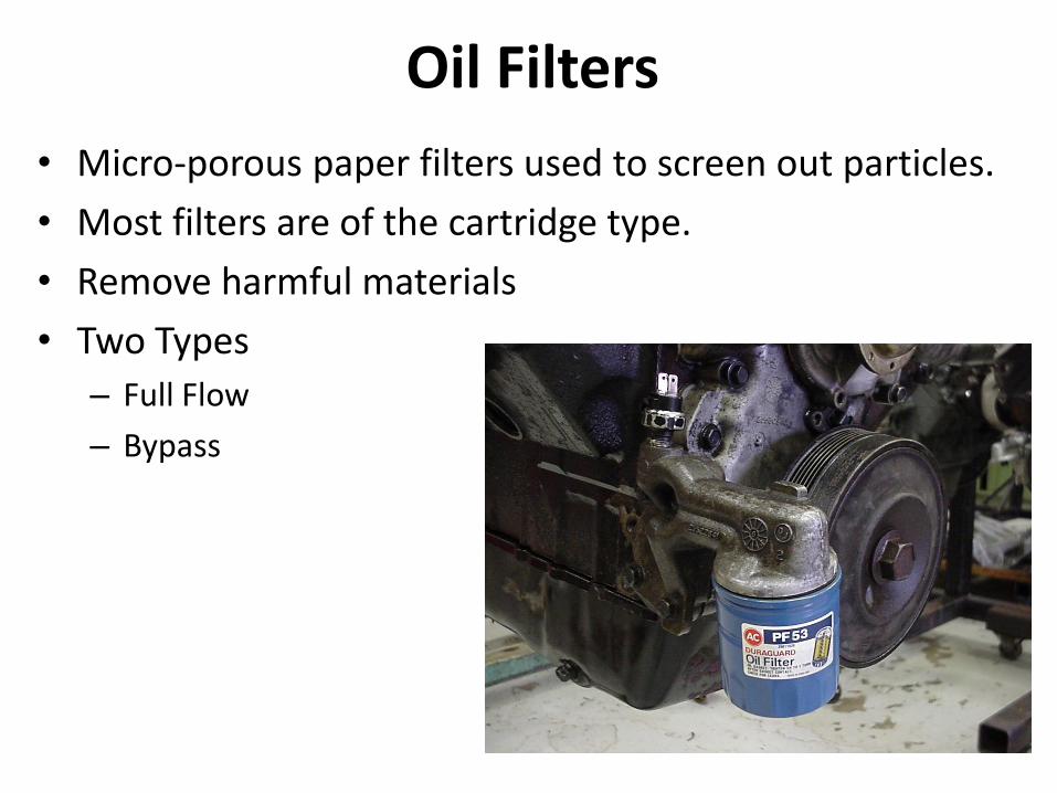
Oil Filters
• Micro-porous paper filters used to screen out particles.
• Most filters are of the cartridge type.
• Remove harmful materials
• Two Types
– Full Flow
– Bypass
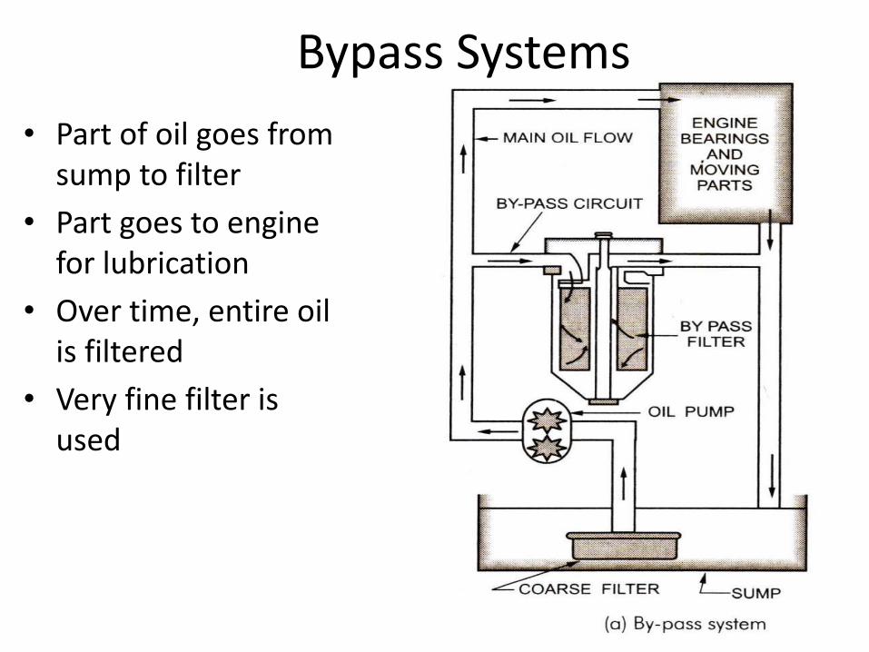
Bypass Systems
• Part of oil goes from sump to filter
• Part goes to engine for lubrication
• Over time, entire oil is filtered
• Very fine filter is used

Full Flow Systems
• All the oil goes to the system through filter
• Relatively a coarse filter is used
• Relief valve is used to ensure oil supply to engine in case of filter clogging

Oil Level and Pressure Indicators
• Dipstick the most simple
• Some engines equipped with an electrical level indicator.
• Oil pressure indicator lamp
• Oil pressure gauge (electrical or mechanical)

Oil Pressure Indicator
• Light or a Gauge • The light turns on or gauge reads low when pressure
drops below specified value (10psi or .7kg/sqcm) • Correct oil pressure is 40-60 psi
Common causes of low oil pressure are: •Low oil level •Worn out pump
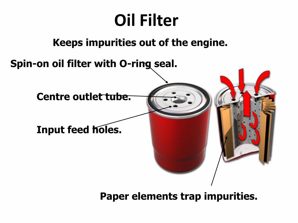
Oil Filter Keeps impurities out of the engine.
Spin-on oil filter with O-ring seal.
Centre outlet tube.
Paper elements trap impurities.
Input feed holes.

Oil Filter Housing
Oil pressure switch.
Oil cooler adapter.
Fed by oil cooler hoses.
Oil filter.
Heat shield.
Bolts to cylinder block.
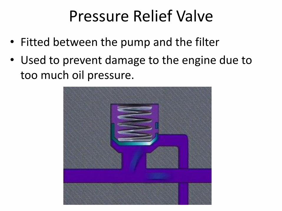
Pressure Relief Valve
• Fitted between the pump and the filter
• Used to prevent damage to the engine due to too much oil pressure.

Oil Pressure sending unit
Electrically sends the signal to the Light or Gauge mounted
on the dash.
If the wires get short the light will come on or the gauge will read high (Full Scale)

OIL CHANGE
•Every 5000/10000 Km Ignoring regular oil change intervals will shorten engine life and performance.

Oil Contamination • Blow-by gases add raw petrol and water to the oil
causing deterioration. • Excessive heat can cause thermal breakdown. • Excessive cranking can dilute oil with petrol. • Cooling gasket leaks will ruin oil causing sludge. • Short distance driving. (which is most trips) • Extensive idling. • Cold weather operation. • Trailer towing. • Excessive heavy loads • Dirty and dusty conditions.