LTPoE++ Extends PoE to 90W with 2011 : LT Journal of Analog Innovation | 7 design features POWER...
6
www.linear.com July 2011 Volume 21 Number 2 IN THIS ISSUE Caption RS485 and RS232 transceivers combined in a single device 12 fast-acting IC protects sensitive circuits from overvoltage and reverse supply connections 23 microprocessor power supply works with FET drivers, DrMOS and power blocks 26 ±5V split-voltage power supply for analog circuits 40 LTPoE ++ Extends PoE to 90W with Reliable and Easy-to-Use Standard Heath Stewart Power over Ethernet, or PoE, is an increasingly popular way to deliver both power and data over existing Ethernet cable, thus freeing applications from the constraint of AC-power proximity. As the number PoE solutions has grown so has the applications’ appetite for power. A new proprietary standard, LTPoE ++™ , satisfies this hunger by extending the PoE and PoE + specifications to 90W of PD delivered power. LTPoE ++ also dramatically reduces engineering complexity in power sourcing equipment (PSEs) and powered devices (PDs) when compared to other power-expansion solutions. Plug-and-play simplicity and safe, robust power delivery are hallmarks of LTPoE ++ . The capabilities of this standard expand the field of Ethernet-powered applications by several orders of magnitude, enabling entirely new classes of PDs, such as power-hungry picocells, base stations or heaters for pan-tilt-zoom cameras. HISTORY OF PoE PoE is a standard protocol for sending DC power over copper Ethernet data wiring. The IEEE group that administers the 802.3 Ethernet data standards added PoE capability in 2003. The original PoE spec, known as 802.3af, allowed for 48V DC power at up to 1 3W. Although the initial specification was widely popular, the 1 3W cap limited the number of possible applica- tions. In 2009, the IEEE released a new standard, known as 802.3at or PoE+, increasing the voltage and current requirements to supply 25.5W of power. (continued on page 4) Linear offers a comprehensive lineup of PoE and LTPoE++ products. The LTC ® 4270/71 chipset reduces PoE costs and complexity by replacing undesireable opto-couplers with a simple off-the-shelf transformer. Like all LTPoE++ products, this chipset also extends PoE delivered power to 90W.
Transcript of LTPoE++ Extends PoE to 90W with 2011 : LT Journal of Analog Innovation | 7 design features POWER...
www.l inear.com
July 2011 Volume 21 Number 2
I N T H I S I S S U E
Caption
RS485 and RS232
transceivers combined in a
single device 12
fast-acting IC protects
sensitive circuits from
overvoltage and reverse
supply connections 23
microprocessor power
supply works with FET
drivers, DrMOS and power
blocks 26
±5V split-voltage power
supply for analog circuits
40
LTPoE++ Extends PoE to 90W with Reliable and Easy-to-Use StandardHeath Stewart
Power over Ethernet, or PoE, is an increasingly popular way to deliver both power and data over existing Ethernet cable, thus freeing applications from the constraint of AC-power proximity. As the number PoE solutions has grown so has the applications’ appetite for power.
A new proprietary standard, LTPoE++™, satisfies this hunger by extending the PoE and PoE+ specifications to 90W of PD delivered power. LTPoE++ also dramatically reduces engineering complexity in power sourcing equipment (PSEs) and powered devices (PDs) when compared to other power-expansion solutions.
Plug-and-play simplicity and safe, robust power delivery are hallmarks of LTPoE++. The capabilities of this standard expand the field of Ethernet-powered applications by several orders of magnitude, enabling entirely new classes of PDs, such as power-hungry picocells, base stations or heaters for pan-tilt-zoom cameras.
HISTORY OF PoE
PoE is a standard protocol for sending DC power over copper Ethernet data
wiring. The IEEE group that administers the 802.3 Ethernet data standards
added PoE capability in 2003. The original PoE spec, known as 802.3af,
allowed for 48V DC power at up to 13W. Although the initial specification
was widely popular, the 13W cap limited the number of possible applica-
tions. In 2009, the IEEE released a new standard, known as 802.3at or PoE+,
increasing the voltage and current requirements to supply 25.5W of power.
(continued on page 4)
Linear offers a comprehensive lineup of PoE and LTPoE++ products. The LTC®4270/71 chipset reduces PoE costs and complexity by replacing undesireable opto-couplers with a simple off-the-shelf transformer. Like all LTPoE++ products, this chipset also extends PoE delivered power to 90W.
4 | July 2011 : LT Journal of Analog Innovation
defines Type 1 PSEs and PDs to include
PSEs and PDs delivering up 13W. Type
2 PSEs and PDs deliver up to 25.5W.
LTPoE++ EVOLUTION
The IEEE PoE+ 25.5W specification had
not yet been finalized when it became
clear that there was a significant
and increasing need for more than
25.5W of delivered power. In response
to this need, the LTPoE++ specifica-
tion reliably allocates up to 90W of
delivered power to an LTPoE++ PD.
The LTPoE++ specification provides reliable
detection and classification extensions
to existing IEEE PoE protocols. LTPoE++
is backward compatible and interoper-
able with existing Type 1 and Type 2 PDs.
Unlike other proprietary power-extending
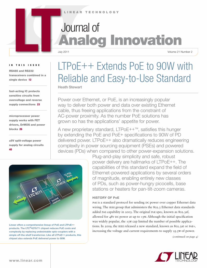
The IEEE standard also defines PoE termi-
nology, as shown in Figure 1. A device
that provides power to the network
is known as a PSE, or power sourcing
equipment, while a device that draws
power from the network is known as
a PD, or powered device. PSEs come in
two types: endpoints (typically network
switches or routers), which send both data
and power, and midspans, which inject
power but pass data through. Midspans
are typically used to add PoE capability
to existing non-PoE networks. Typical
PD applications are IP phones, wireless
access points, security cameras, cellular
femtocells, picocells and base stations.
The IEEE PoE+ specification specifies
backward compatibility with 802.3af
PSEs and PDs. The PoE+ specification
(LTPoE++, continued from page 1)
–
DATA PAIR
DATA PAIRVEE SENSE GATE OUT
0.25Ω
PSECONTROLLER
DGND AGND
–55V
RJ45
1
2
1
2
3
6
3
6
RJ45
PSE PD
RCLASS
–VIN
PWRGD
–VOUT
PDCONTROLLER
GNDDC/DC
CONVERTER
+VOUT
GND
SPARE PAIR
SPARE PAIR
4
5
4
5
7
8
7
8
Figure 1. Typical PoE system
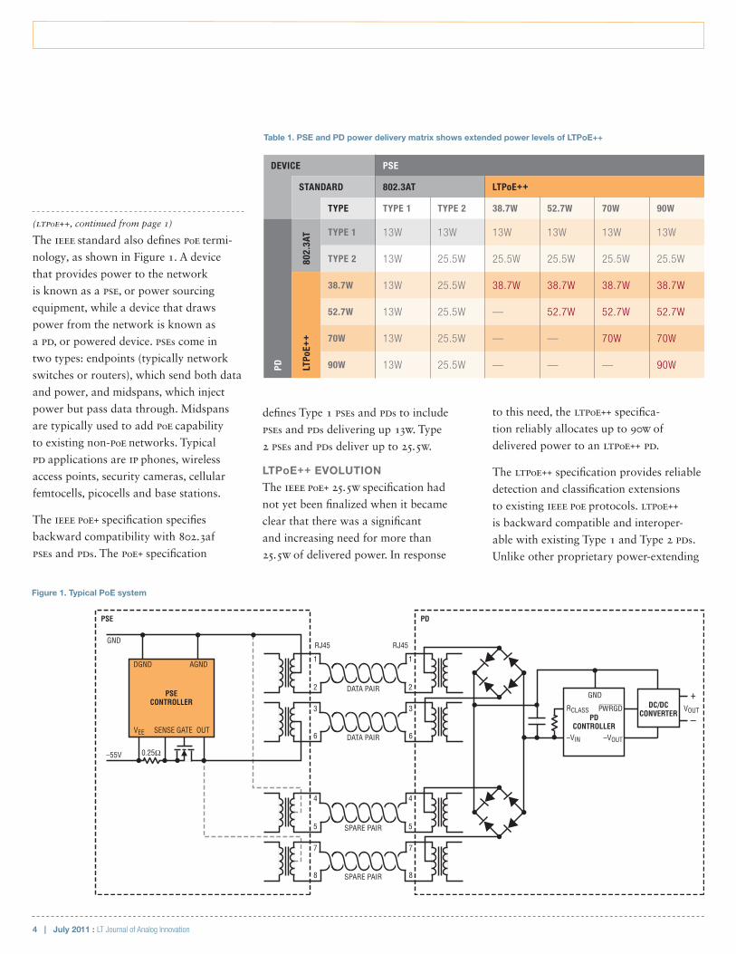
Table 1. PSE and PD power delivery matrix shows extended power levels of LTPoE++
DEVICE PSE
STANDARD 802.3AT LTPoE++
TYPE TYPE 1 TYPE 2 38.7W 52.7W 70W 90W
PD
802.
3AT TYPE 1 13W 13W 13W 13W 13W 13W
TYPE 2 13W 25.5W 25.5W 25.5W 25.5W 25.5W
LTPo
E++
38.7W 13W 25.5W 38.7W 38.7W 38.7W 38.7W
52.7W 13W 25.5W — 52.7W 52.7W 52.7W
70W 13W 25.5W — — 70W 70W
90W 13W 25.5W — — — 90W
July 2011 : LT Journal of Analog Innovation | 5
design features
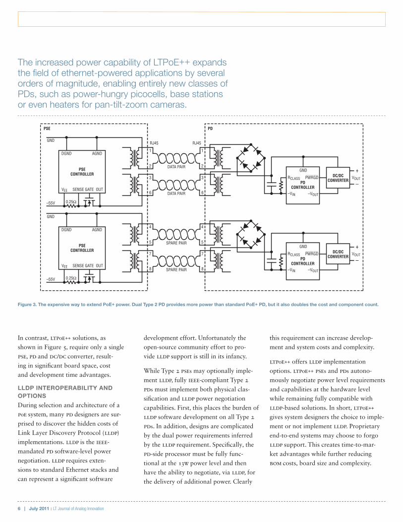
Type 2” topology is shown in Figure 3.
The main problem with this strategy is
that it doubles the number of compo-
nents, thus doubling PSE and PD costs.
Additionally, robust design considerations
require two DC/DC converters at the PD,
one for each component PD, where each
DC/DC converter is a relatively complex
flyback or forward isolated supply.
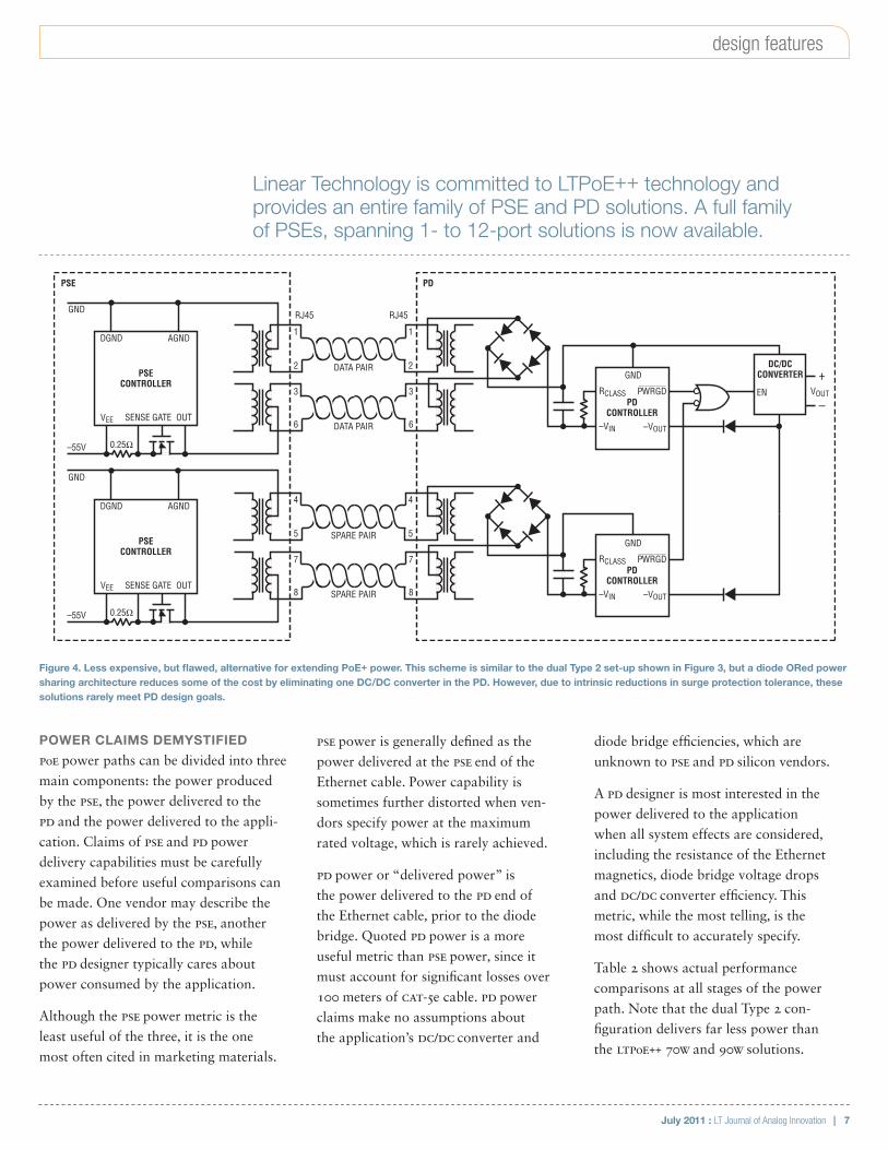
One of the DC/DC converters in a dual
Type 2 set-up can be eliminated by
ORing the PD’s output power as shown
in Figure 4. This approach still requires
two PSEs and two PDs, with the associ-
ated cost and space disadvantages. The
voltage drop incurred by the power
ORing diodes might be considered a fair
trade-off for the savings gained by using
a single DC/DC converter. In most cases
diode ORed power sharing architectures
remain attractive until surge protection
testing begins. Due to intrinsic reduc-
tions in surge protection tolerance, these
solutions rarely meet PD design goals.
power allocation scheme violating the
IEEE-mandated detection resistance
specifications risks damaging and
destroying non-PoE Ethernet devices.
The following rules define any detec-
tion methodology for the highest lev-
els of safety and interoperability.
•Priority 1: Don’t turn on things you
shouldn’t turn on.
•Priority 2: Do turn on things you
should.
Linear Technology PSEs provide extremely
robust detection schemes utilizing four-
point detection. False positive detections
are minimized by checking for signa-
ture resistance with both forced-current
and forced voltage measurements.
LTPoE++ ADVANTAGES
Standard PoE PSEs use two of the four
available Ethernet cable pairs for power.
Some power-extending topologies use
two PSEs and two PDs over one cable
to deliver 2 × 25.5W power. This “dual
solutions, Linear’s LTPoE++ provides
mutual identification between the
PSE and PD. LTPoE++ PSEs can differenti-
ate between an LTPoE++ PD and all other
types of IEEE compliant PDs, allowing
LTPoE++ PSEs to remain compliant and
interoperable with existing equipment.
LTPoE++ PSEs and PDs seamlessly interoper-
ate with IEEE 802.3at Type 1 and Type 2
devices. Type 1 PSEs generally encompass
802.3af functionality at and below 13W.
Type 2 PSEs extend traditional PoE to 25.5W.
The following points reference Table 1:
•Type 1 PSEs will power all Type 1, Type
2 and LTPoE++ PDs with up to 13W.
•Type 2 PSEs will power Type 1
PDs with up to 13W and provide
25.5W to Type 2 and LTPoE++ PDs.
•LTPoE++ PDs can power up with lim-
ited functionality even when attached
to traditional Type 1 and 2 PSEs.
•LTPoE++ PSEs interoperate with Type
1 and Type 2 PDs. LTPoE++ PDs are
powered to the designed limit of
the LTPoE++ PSE. When an LTPoE++
PD is identified, the PD will be pow-
ered up if the PSE power rating meets
or exceeds the requested PD power.
For example, a 52.7W LTPoE++ PSE can
power both 38.7W and 52.7W PDs.
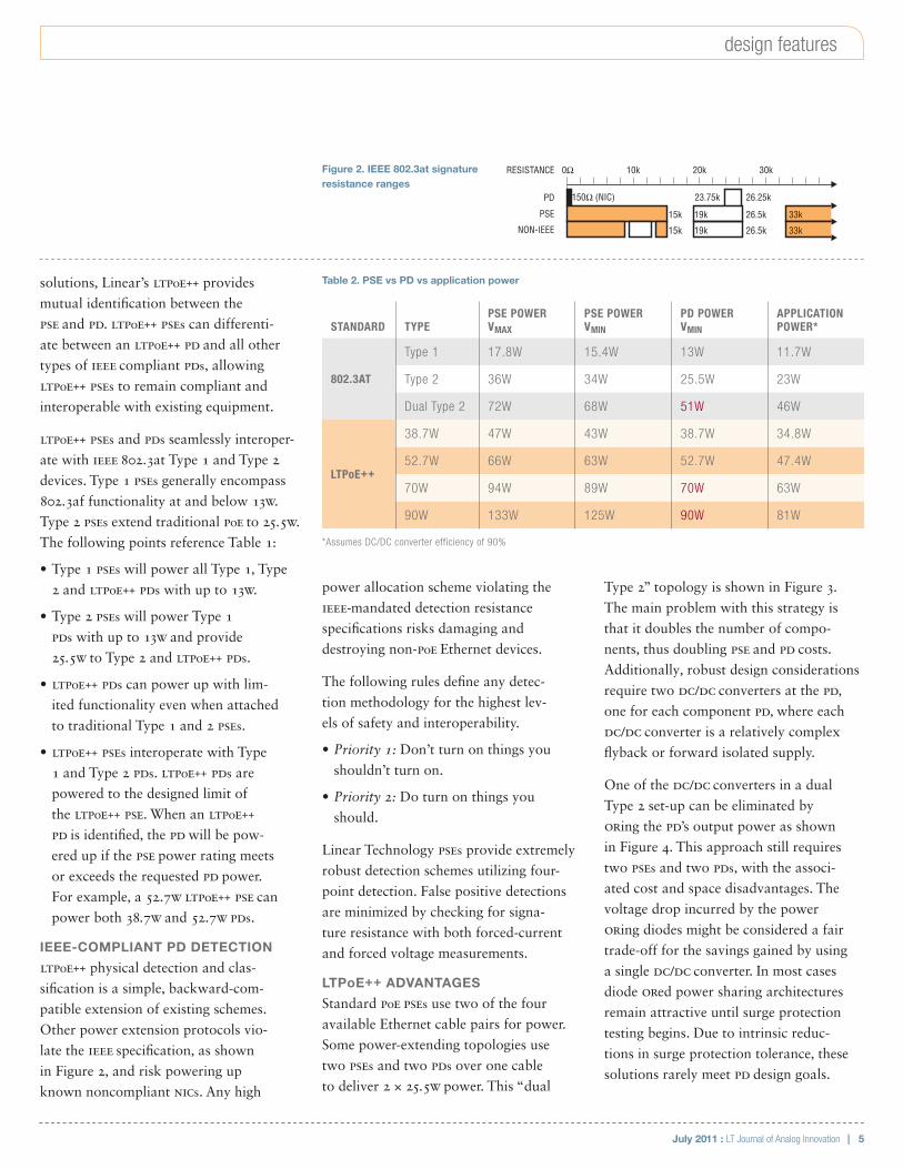
IEEE-COMPLIANT PD DETECTION
LTPoE++ physical detection and clas-
sification is a simple, backward-com-
patible extension of existing schemes.
Other power extension protocols vio-
late the IEEE specification, as shown
in Figure 2, and risk powering up
known noncompliant NICs. Any high
Table 2. PSE vs PD vs application power
STANDARD TYPEPSE POWER VMAX
PSE POWER VMIN
PD POWER VMIN
APPLICATION POWER*
802.3AT
Type 1 17.8W 15.4W 13W 11.7W
Type 2 36W 34W 25.5W 23W
Dual Type 2 72W 68W 51W 46W
LTPoE++
38.7W 47W 43W 38.7W 34.8W
52.7W 66W 63W 52.7W 47.4W
70W 94W 89W 70W 63W
90W 133W 125W 90W 81W
*Assumes DC/DC converter efficiency of 90%
RESISTANCE
PD
PSE
0Ω 10k
15k 19k 26.5k
26.25k23.75k150Ω (NIC)
20k 30k
33k
NON-IEEE 15k 19k 26.5k 33k
Figure 2. IEEE 802.3at signature resistance ranges
6 | July 2011 : LT Journal of Analog Innovation
development effort. Unfortunately the
open-source community effort to pro-
vide LLDP support is still in its infancy.
While Type 2 PSEs may optionally imple-
ment LLDP, fully IEEE-compliant Type 2
PDs must implement both physical clas-
sification and LLDP power negotiation
capabilities. First, this places the burden of
LLDP software development on all Type 2
PDs. In addition, designs are complicated
by the dual power requirements inferred
by the LLDP requirement. Specifically, the
PD-side processor must be fully func-
tional at the 13W power level and then
have the ability to negotiate, via LLDP, for
the delivery of additional power. Clearly
this requirement can increase develop-
ment and system costs and complexity.
LTPoE++ offers LLDP implementation
options. LTPoE++ PSEs and PDs autono-
mously negotiate power level requirements
and capabilities at the hardware level
while remaining fully compatible with
LLDP-based solutions. In short, LTPoE++
gives system designers the choice to imple-
ment or not implement LLDP. Proprietary
end-to-end systems may choose to forgo
LLDP support. This creates time-to-mar-
ket advantages while further reducing
BOM costs, board size and complexity.
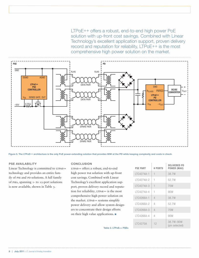
In contrast, LTPoE++ solutions, as
shown in Figure 5, require only a single
PSE, PD and DC/DC converter, result-
ing in significant board space, cost
and development time advantages.
LLDP INTEROPERABILITY AND OPTIONS
During selection and architecture of a
PoE system, many PD designers are sur-
prised to discover the hidden costs of
Link Layer Discovery Protocol (LLDP)
implementations. LLDP is the IEEE-
mandated PD software-level power
negotiation. LLDP requires exten-
sions to standard Ethernet stacks and
can represent a significant software
–
DATA PAIR
DATA PAIRVEE SENSE GATE OUT
0.25Ω
PSECONTROLLER
DGND AGND
–55V
RJ45
1
2
1
2
3
6
3
6
RJ45
PSE PD
RCLASS
–VIN
PWRGD
–VOUT
PDCONTROLLER
GNDDC/DC
CONVERTER
+VOUT
GND
SPARE PAIR
SPARE PAIR
4
5
4
5
7
8
7
8
–VEE SENSE GATE OUT
0.25Ω
PSECONTROLLER
DGND AGND
–55V
RCLASS
–VIN
PWRGD
–VOUT
PDCONTROLLER
GNDDC/DC
CONVERTER
+VOUT
GND
Figure 3. The expensive way to extend PoE+ power. Dual Type 2 PD provides more power than standard PoE+ PD, but it also doubles the cost and component count.
The increased power capability of LTPoE++ expands the field of ethernet-powered applications by several orders of magnitude, enabling entirely new classes of PDs, such as power-hungry picocells, base stations or even heaters for pan-tilt-zoom cameras.
July 2011 : LT Journal of Analog Innovation | 7
design features
POWER CLAIMS DEMYSTIFIED
PoE power paths can be divided into three
main components: the power produced
by the PSE, the power delivered to the
PD and the power delivered to the appli-
cation. Claims of PSE and PD power
delivery capabilities must be carefully
examined before useful comparisons can
be made. One vendor may describe the
power as delivered by the PSE, another
the power delivered to the PD, while
the PD designer typically cares about
power consumed by the application.
Although the PSE power metric is the
least useful of the three, it is the one
most often cited in marketing materials.
PSE power is generally defined as the
power delivered at the PSE end of the
Ethernet cable. Power capability is
sometimes further distorted when ven-
dors specify power at the maximum
rated voltage, which is rarely achieved.
PD power or “delivered power” is
the power delivered to the PD end of
the Ethernet cable, prior to the diode
bridge. Quoted PD power is a more
useful metric than PSE power, since it
must account for significant losses over
100 meters of CAT-5e cable. PD power
claims make no assumptions about
the application’s DC/DC converter and
diode bridge efficiencies, which are
unknown to PSE and PD silicon vendors.
A PD designer is most interested in the
power delivered to the application
when all system effects are considered,
including the resistance of the Ethernet
magnetics, diode bridge voltage drops
and DC/DC converter efficiency. This
metric, while the most telling, is the
most difficult to accurately specify.
Table 2 shows actual performance
comparisons at all stages of the power
path. Note that the dual Type 2 con-
figuration delivers far less power than
the LTPoE++ 70W and 90W solutions.
–
DATA PAIR
DATA PAIRVEE SENSE GATE OUT
0.25Ω
PSECONTROLLER
DGND AGND
–55V
RJ45
1
2
1
2
3
6
3
6
RJ45
PSE PD
RCLASS
–VIN
PWRGD
–VOUT
PDCONTROLLER
GNDDC/DC
CONVERTER +VOUT
GND
SPARE PAIR
SPARE PAIR
4
5
4
5
7
8
7
8VEE SENSE GATE OUT
0.25Ω
PSECONTROLLER
DGND AGND
–55V
RCLASS
–VIN
PWRGD
–VOUT
PDCONTROLLER
GND
GND
EN
Figure 4. Less expensive, but flawed, alternative for extending PoE+ power. This scheme is similar to the dual Type 2 set-up shown in Figure 3, but a diode ORed power sharing architecture reduces some of the cost by eliminating one DC/DC converter in the PD. However, due to intrinsic reductions in surge protection tolerance, these solutions rarely meet PD design goals.
Linear Technology is committed to LTPoE++ technology and provides an entire family of PSE and PD solutions. A full family of PSEs, spanning 1- to 12-port solutions is now available.
8 | July 2011 : LT Journal of Analog Innovation
PSE AVAILABILITY
Linear Technology is committed to LTPoE++
technology and provides an entire fam-
ily of PSE and PD solutions. A full family
of PSEs, spanning 1- to 12-port solutions
is now available, shown in Table 3.
CONCLUSION
LTPoE++ offers a robust, end-to-end
high power PoE solution with up-front
cost savings. Combined with Linear
Technology’s excellent application sup-
port, proven delivery record and reputa-
tion for reliability, LTPoE++ is the most
comprehensive high power solution on
the market. LTPoE++ systems simplify
power delivery and allow system design-
ers to concentrate their design efforts
on their high value applications. n
Figure 5. The LTPoE++ architecture is the only PoE power-extending solution that provides 90W at the PD while keeping complexity and costs in check.
–
DATA PAIR
DATA PAIRVEE SENSE GATE OUT
0.25Ω
LTPoE++PSE
CONTROLLER
DGND AGND
–55V
RJ45
1
2
1
2
3
6
3
6
RJ45
PSE PD
RCLASS
–VIN
PWRGD
–VOUT
LTPoE++PD
CONTROLLER
GNDDC/DC
CONVERTER
+VOUT
GND
SPARE PAIR
SPARE PAIR
4
5
4
5
7
8
7
8
LTPoE++ offers a robust, end-to-end high power PoE solution with up-front cost savings. Combined with Linear Technology’s excellent application support, proven delivery record and reputation for reliability, LTPoE++ is the most comprehensive high power solution on the market.
PSE PART # PORTSDELIVERED PD POWER (MAX)
LTC4274A-1 1 38.7W
LTC4274A-2 1 52.7W
LTC4274A-3 1 70W
LTC4274A-4 1 90W
LTC4266A-1 4 38.7W
LTC4266A-2 4 52.7W
LTC4266A-3 4 70W
LTC4266A-4 4 90W
LTC4270A 1238.7W–90W (pin selected)
Table 3. LTPoE++ PSEs