LTE/LTE A Self Optimization Network - krnet.or.krB9... · LTE/LTE ‐A Self ... Automatic PCI...
26
LTE/LTE‐A Self Optimization Network Jungshin Park Jungshin Park [email protected] DMC R&D Center Samsung Electronics Co Samsung Electronics Co. June 28, 2011
Transcript of LTE/LTE A Self Optimization Network - krnet.or.krB9... · LTE/LTE ‐A Self ... Automatic PCI...

LTE/LTE‐ASelf Optimization Network
Jungshin ParkJungshin Park [email protected]
DMC R&D CenterSamsung Electronics CoSamsung Electronics Co.
June 28, 2011

ContentsContents
0 Introduction0. Introduction
I. 3GPP SON – 3GPP SON Features– Release10 Enhancements
All rights reserved - KRNET 2011 2

0 Introduction0. Introduction

SON (Self Optimization Network)SON (Self Optimization Network)
• SON (Self Optimization Network)• SON (Self Optimization Network)– Self‐Organizing Networks (SON) is a process that involves Network Elements (NEs) in Radio Access Networks (RAN)
and Core networks to enable automatic configuration, to measure / analyze performance data, and to fine tune network attributes in order to achieve optimal performance.
• SON Architecture– Centralized SON Model
• Client‐Server type: client collects and reports information to the server;yp pserver decides and distributes optimized parameters
• Signaling happens between server and client entity
– Distributed SON Model• Peer‐to‐peer type: each entity optimizes and informs neighboring entity of its
parametersp• Signaling happens between peer entities
All rights reserved - KRNET 2011 4

SON FrameworkSON Framework
All rights reserved - KRNET 2011 5

I 3GPP SONI. 3GPP SON
3GPP SON Features3GPP SON Features
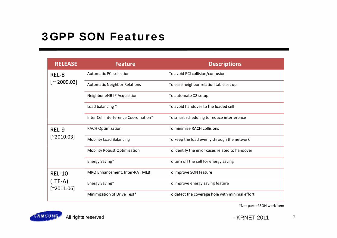
RELEASE Feature DescriptionsRELEASE Feature Descriptions
REL‐8[ ~ 2009.03]
Automatic PCI selection To avoid PCI collision/confusion
Automatic Neighbor Relations To ease neighbor relation table set up
Neighbor eNB IP Acquisition To automate X2 setup
Load balancing * To avoid handover to the loaded cell
Inter Cell Interference Coordination* To smart scheduling to reduce interferenceg
REL‐9[~2010.03]
RACH Optimization To minimize RACH collisions
Mobility Load Balancing To keep the load evenly through the network
Mobility Robust Optimization To identify the error cases related to handover
Energy Saving* To turn off the cell for energy saving
REL 10 MRO Enhancement Inter‐RAT MLB To improve SON featureREL‐10 (LTE‐A)[~2011.06]
MRO Enhancement, Inter RAT MLB To improve SON feature
Energy Saving* To improve energy saving feature
Minimization of Drive Test* To detect the coverage hole with minimal effort
All rights reserved - KRNET 2011 7
*Not part of SON work item

Automatic PCI SelectionAutomatic PCI Selection
• PCI (Physical Cell Identity) is determined by eNBPCI (Physical Cell Identity) is determined by eNB1) The OAM system provides an initial list of PCI values.2) The eNB may shorten the list by removing the following PCI‐s which
are already used by neighbors: • PCI‐s reported by UEs;• PCI s reported over the X2 interface by neighboring eNBs• PCI‐s reported over the X2 interface by neighboring eNBs• PCI‐s acquired through other implementation dependent methods(e.g., by self‐scanning for downlink signals)
) h l l d l f h d d l3) The eNB selects a PCI value randomly from the updated list
All rights reserved - KRNET 2011 8

Automatic Neighbor Relation (ANR)Automatic Neighbor Relation (ANR)
• Neighbor Relation Table (NRT) is configured/updatedNeighbor Relation Table (NRT) is configured/updated automatically1) UE reports neighboring cell information (RRC signaling)2) eNB may consult with OAM to update its tablecf. O&M may add or delete NRs at any time
• Components of NRT– TCI (Target Cell Information)
• ECGI, TAI, PCI• PLMN IDs, etc…PLMN IDs, etc…
– Neighbor Relation Attribute• No Remove, ,No HO, No X2, etc
All rights reserved - KRNET 2011 9

Automatic Neighbor Relation (ANR)Automatic Neighbor Relation (ANR)
• Report of neighboring cell information by UEReport of neighboring cell information by UE
<Procedures> [TS36.300]
Cell APhy-CID=3Global-CID =17
Cell BPhy-CID=5Global-CID =19
1. UE sends a measurement report regarding cell B (PCI) but not ECGI.
2. ENB instructs the UE using PCI to read ECGI (e.g. PLMN ID, CSG
0) report(Phy-CID=5, strong signal)
2b) Read BCH()3) Report Global-CID 19
1) New Phy-CID is detectedread ECGI (e.g. PLMN ID, CSG indicator, Cell ID)
3. When the UE found ECGI, it reports the detected ECGI, the tracking area code PLMN IDs
2) Report Global-CID Request (Target Phy-CID=5)
CID=19(TAC, PLMN ID, …)
code, PLMN IDs4. ENB decides to add PCI, ECGI into
the Neighbor Relation Table (ERT)– Lookup address– Update– If needed, performs X2 SETUP
All rights reserved - KRNET 2011 10

Automatic Neighbor Relation (ANR)Automatic Neighbor Relation (ANR)
• Update of NRTUpdate of NRT
All rights reserved - KRNET 2011 11

Neighbor eNB IP AcquisitionNeighbor eNB IP Acquisition
• The IP address of a new neighbor eNB is acquired throughThe IP address of a new neighbor eNB is acquired through backhaul communication
0) UE is served by eNB‐011) eNB‐02 is installed, sets up S1 with MME‐02,
d i i i diand starts activating its Radio2) UE detects and reports eNB‐02 (PCI)3) ANR is performed4) ‐ 6) SON Info Request (eNB02 IP) is transmitted4) 6) SON Info Request (eNB02 IP) is transmitted
to eNB‐017) ‐ 9) SON Info Reply (eNB02 IP) is sent back to
eNB‐01
All rights reserved - KRNET 2011 12

Load BalancingLoad Balancing
• eNB may control UE HOs based on the load information of its• eNB may control UE HOs based on the load information of its neighbor eNBs
<X2 Support for Load Balancing>• Subscription for Measurements
– Done by RESOUCE STATUS REQUEST/RESPONSE
eNB1 eNB2
RESOURCE STATUS REQUEST
• Start and Stop the requested measurements• Subscribe required measurements• Specify the periodicity of the UPDATE
• Periodic Updated Measurements
RESOURCE STATUS RESPONSE
NB NB– Done by RESOURCE STATUS UPDATE– Measurement Information
• Radio Resource Status (DL/UL total/GBR/non‐GBR PRB usages ‐ percentages)
eNB1 eNB2
RESOURCE STATUS UPDATE
• UL/DL S1 TNL Load Indicator (Low/medium/high/…)• Hardware Load Indicator (Low/medium/high/overload)
All rights reserved - KRNET 2011 13

Inter-Cell Interference Coordination (ICIC)Inter Cell Interference Coordination (ICIC)
• To mitigate inter cell interference load and interference co• To mitigate inter‐cell interference, load and interference co‐ordination information are shared between Neighbor eNBs in the same FA bandthe same FA band
<X2 Support for Interference Management>UL ‘Hi h I t f I di t ’(HII) ti i di t• UL ‘High Interference Indicator’(HII) – proactive indicator
o The receiving eNB should try to avoid scheduling cell edge UEs in its cells for the concerned PRBs
• UL ‘Interference Overload Indicator’ (IOI) – reactive indicatoro interference level experienced by the indicated cell on all
eNB1
LOAD INFORMATION
eNB2
o interference level experienced by the indicated cell on all resource blocks
• DL ‘Relative Narrowband Tx Power’ (RNTP) – proactive indicator?
o whether downlink transmission power is lower than the value indicated by the RNTP Threshold IE
All rights reserved - KRNET 2011 14

Inter-Cell Interference Coordination (ICIC)Inter Cell Interference Coordination (ICIC)
• Example scenario• Example scenario– Cell1 generates and reports load and interference coordination
information to Cell21) UL HII bit set: UE at the edge may cause interference to Cell22) UL IOI: A PRB of Cell1 suffers interference {high, medium, low, …}3) RNTP bit set: The power for a DL PRB may exceed RNTP threshold3) RNTP bit set: The power for a DL PRB may exceed RNTP threshold
Cell1
Cell2(target)
1) PRB resource allocated to the edge UE
Cell4UL traffic from the UE
Potential interferenceto Cell2 by the UE
Cell1
Cell3
All rights reserved - KRNET 2011 15

RACH OptimizationRACH Optimization
• To reduce possible RACH (Random Access Channel) resources• To reduce possible RACH (Random Access Channel) resources collisions, configuration information is shared between eNBs– RACH Resources InformationRACH Resources Information
1) Radio resource information for RACH procedures (time/freq information): PRACH‐FrequencyOffset, PRACH‐ConfigurationIndex
2) P t f ti RACH P bl2) Parameters for generating RACH Preambles: RootSequenceIndex, ZeroCorrectionZoneConfiguration, HighSpeedFlag
– X2 Support for RACH optimization• “PRACH‐Configuration” information is delivered by the X2 Setup and NB Configuration Update messages
All rights reserved - KRNET 2011 16

Mobility Load Balancing (MLB) (1/3)Mobility Load Balancing (MLB) (1/3)
• To balance the load between neighbor cells capacity and• To balance the load between neighbor cells, capacity and handover parameters information are shared between eNBs
• MLB Framework1) Load reporting function1) Load reporting function2) Handover function3) Adapting HO parameters
All rights reserved - KRNET 2011 17

Mobility Load Balancing (MLB) (2/3)
• Load Reporting Function
Mobility Load Balancing (MLB) (2/3)
• Load Reporting Function– Exchanges capacity information using X2 Resource Status Updatemsg.
IE/Group Name Presence Range IE type and reference Semantics descriptionIE/Group Name Presence Range IE type and reference Semantics description
Composite Available Capacity Downlink M Composite Available Capacity 9.2.45
For the Downlink
Composite Available Capacity Uplink M Composite Available Capacity 9.2.45
For the Uplink
IE/Group Name Presence Range IE type and reference Semantics description
Cell Capacity Class Value O INTEGER (1..100,...) Value 1 shall indicate the minimum cell capacity, and 100 shall indicate the maximum cell capacity. There should be li l i b ll ilinear relation between cell capacity and Cell Capacity Class Value
Capacity Value M INTEGER (0..100) Value 0 shall indicate no available capacity, and 100 shall indicate maximum available capacity . Capacity Value should be measured on a linear
l
cf. For the Inter‐RAT MLB, S1 ENB/MME Direct Information Transfermessage isused instead
scale.
All rights reserved - KRNET 2011
used instead
18

Mobility Load Balancing (MLB) (3/3)
• Adopting Handover Parameters
Mobility Load Balancing (MLB) (3/3)
• Adopting Handover Parameters– eNB requests its neighbors to adjust mobility parameters– Using X2 Mobility Change Request/AcknowledgemessageUsing X2 Mobility Change Request/Acknowledgemessage
• Mobility load balancing parameters: IE/Group Name Presence Range IE type and reference Semantics description
Message Type M 9 2 13Message Type M 9.2.13eNB1 Cell ID M ECGI
9.2.14eNB2 Cell ID M ECGI
9.2.14eNB1 Mobility Parameters O Mobility Parameters Information Configuration change ineNB1 Mobility Parameters O Mobility Parameters Information
9.2.48Configuration change in eNB1 cell.
eNB2 Proposed Mobility Parameters M Mobility Parameters Information 9.2.48
Proposed configuration change in eNB2 cell.
Cause M 9.2.6
IE/Group Name IE type and reference Semantics descriptionHandover Trigger Change INTEGER (‐20..20) The actual value is IE value * 0.5 dB.
Cell Specific Offset
All rights reserved - KRNET 2011 19

Mobility Robust OptimizationMobility Robust Optimization
• To enable adjustment of HO parameters HO errors reported• To enable adjustment of HO parameters, HO errors, reported by UE, can be notified to eNBs by backhaul signaling– 3 Types of HO errors are reported3 Types of HO errors are reported
• Too late handover• Too early handover• Handover to the wrong cell
All rights reserved - KRNET 2011 20

Mobility Robust Optimization
• Report of HO errors
Mobility Robust Optimization
• Report of HO errors: 1) Too Late Handover
All rights reserved - KRNET 2011 21

Mobility Robust Optimization
• Report of HO errors
Mobility Robust Optimization
• Report of HO errors2) Too Early Handover
All rights reserved - KRNET 2011 22

Mobility Robust Optimization
• Report of HO errors
Mobility Robust Optimization
• Report of HO errors 3) HO to the wrong Cell
All rights reserved - KRNET 2011 23

MRO Enhancement (1/2)MRO Enhancement (1/2)
• MRO for RRC re establishment failure• MRO for RRC re‐establishment failure– UE provides the RLF Report to an eNB during RRC connection setup
after the re‐establishment failure– Availability of the RLF Report at the RRC connection setup procedure is
the indication that the UE recovers from a connection failureTh NB i i th RLF R t f d th t t th NB– The eNB receiving the RLF Report may forward the report to the eNBthat served the UE before the reported connection failure or to the eNB where the mobility configuration caused the failure
– RLF Report may be used to identify coverage hole
All rights reserved - KRNET 2011 24

MRO Enhancement (2/2)MRO Enhancement (2/2)
• Inter RAT MRO Enhancement• Inter‐RAT MRO Enhancement– For detection of too early inter‐RAT handover with no RLF– Target is configured with thresholds during HO preparation phaseg g g p p p
• RSRP, RSRQ, timer, Frequency
– Target eNB detects and reports unnecessary HO events to source eNB
All rights reserved - KRNET 2011 25

MLB EnhancementMLB Enhancement
• Inter RAT MLB Support• Inter‐RAT MLB Support– Event‐triggered Inter‐RAT cell load reporting
• Reports are sent when crossing cell load thresholdepo ts a e se t e c oss g ce oad t es o d• Reports can have information for multiple cells
– Reporting parameters• Cell Capacity Class value
– UL/DL relative capacity indicator
• Capacity value– UL/DL available capacity as percentage of total cell capacity
All rights reserved - KRNET 2011 26