
L&T Ball Valves 3-Piece Design - …orientalgroup.yolasite.com/resources/L&T 3 Pc Ball_valve.pdfL&T...
8
www.lntvalves.com 3-Piece Design L&T Ball Valves www.lntvalves.com
Transcript of L&T Ball Valves 3-Piece Design - …orientalgroup.yolasite.com/resources/L&T 3 Pc Ball_valve.pdfL&T...

www.lntvalves.com
3-Piece DesignL&T Ball Valves
www.lntvalves.com

Larsen & ToubroLarsen & Toubro (L&T) is a US $8.5 billion engineering and construction company, with a strong presence in manufacturing, services and Information Technology.
L&T was founded in 1938 by Danish engineers, Henning Holck-Larsen and Soren Kristian Tourbo. A strongcustomer-focused approach and a constant quest for world-class quality have enabled L&T to achieve remarkable success in its major lines of business for over six decades.
L&T offers proven solutions for the oil and gas, refinery, petrochemical, fertilizer, chemical, power and construction industries. The company has an international reputation for technological sophistication and execution of large projects.
Marketing NetworkThe Valves Business Group of L&T has offices in India, USA and China, and strategic alliances with integrated valve distributors worldwide. An experienced team of valve specialists supports the marketing network.
L&T - VBG has an impressive track record of supplying valves to global oil majors and EPC contractors in the USA, Europe, the Middle East, Africa and Asia-Pacific.
Design & Engineering
Quality Assurance & ManufactureL&T Valves are manufactured in a modern facility whose quality management system conforms to international standards.
All stages in manufacture of L&T valves are controlled by a stringent quality assurance plan. Elaborate systems are in place to guarantee casting integrity and to ensure that mechanical and chemical properties are in line with customer specifications.
Consistent quality is L&T’s hallmark.
L&T has in-house valves design capabilities for:New Product DesignDesign OptimizationProduct Enhancement
These strengths are utilized to ensure that the design of each L&T valve complies with end-user requirements.
THE L&T ADVANTAGEOver 40 years of experience in supplying valves to discerning customers and contractors worldwide. This expertise is now leveraged to bring you reliable and cost-effective flow-control solutions.
1

www.lntvalves.com
Features and BenefitsSeat DesignThe cavity pressure relieving seats ensure that the pressure generated through media expansion when the valve is in close position is safely relieved. This equalizes the pressure over upstream when used in high differential pressure applications and thereby reduces the operating torque. The pressure-loaded, fully molded seats provide contact between a precision-machined ball and prevent damage to the seats under high pressure.
Unique seat geometry provides bi-directional bubble-tight shut-off and reduced operating torque.
Mirror-Finished Solid BallThe ball is polished to a mirror finish to ensure smooth contact of the seating surfaces and prevents build up of contaminants in hygienic applications. Thesolid stainless steel ball ensures corrosion and pressure resistance for all critical applications. The ball is provided with a pressure equalizing hole to balance cavity pressure with line pressure when valve is open.
Anti Blow Out & Live Loaded StemBlowout proof design helps in the prevention of accidents and injuries. The bottom entry live loaded stem self adjusts with the pressure and temperature fluctuations. Two Belleville springs allow the valves to perform exceptionally during high cycling applications and they also compensate for packing wear. Belleville springs provide a constantloading of the stem seal system to counter balance the thermal expansion, contraction and wear. This system automatically adjusts to prevent leakage through the stem area of the valve. Stem Thrust Seal prevents galling, reduces torque and provides secondary stem seal.
Antistatic FeatureThree-piece Ball Valves are provided with built-in antistatic design features. This is achieved through 35% carbon-filled PTFE stem thrust seal and gland packings. They provide electrical continuity between the body and the stem, discharging any build-up of static charge.
Swing-Out Design For Easy MaintenanceThree-piece ball valves are in-line repairable as the center section swings out. This feature is well suited for use in piping systems where line breaks arerequired. This design ensures that the seats, seals and ball can all be replaced quickly and easily without disturbing pipe alignment.
Belleville Springs- Live LoadingStem Thrust SealAnti Blowout StemShoulder
PressureEqualising Slots
2
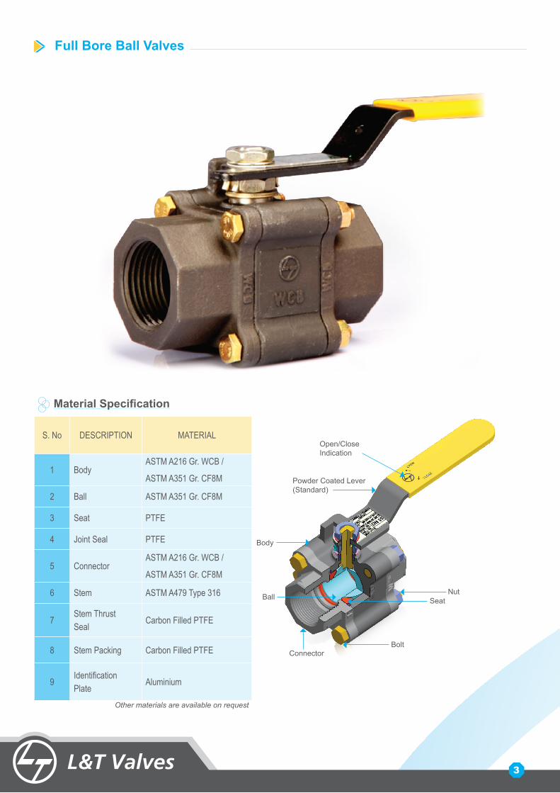
Full Bore Ball Valves
Body
S. No DESCRIPTION MATERIAL
1 BodyASTM A216 Gr. WCB /
ASTM A351 Gr. CF8M
2 Ball ASTM A351 Gr. CF8M
3 Seat PTFE
4 Joint Seal PTFE
5 ConnectorASTM A216 Gr. WCB /
ASTM A351 Gr. CF8M
6 Stem ASTM A479 Type 316
7Stem Thrust Seal
Carbon Filled PTFE
8 Stem Packing Carbon Filled PTFE
9Identification Plate
Aluminium
Material Specification
Open/CloseIndication
BallNut
Seat
BoltConnector
Powder Coated Lever(Standard)
Other materials are available on request
3
www.lntvalves.com
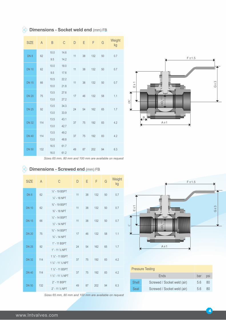
SIZE A B C D E F G Weight kg
DN 8 6210.0
9.5
14.6
14.211 38 132 50 0.7
DN 10 6210.0
9.5
18.0
17.611 38 132 50 0.7
DN 15 6610.5
10.0
22.2
21.811 38 132 50 0.7
DN 20 7513.5
13.0
27.6
27.217 46 132 58 1.1
DN 25 9213.5
13.0
34.3
33.924 54 162 65 1.7
DN 32 11413.5
13.0
43.1
42.737 75 192 83 4.2
DN 40 11413.5
13.0
49.2
48.837 75 192 83 4.2
DN 50 13216.5
16.0
61.7
61.249 87 202 94 6.3
Dimensions - Socket weld end (mm) FB
Pressure Testing
Ends bar psiShell Screwed / Socket weld (air) 5.6 80Seat Screwed / Socket weld (air) 5.6 80
SIZE A C D E F G Weight kg
DN 8 62¼” - 19 BSPT
11 38 132 50 0.7¼” - 18 NPT
DN 10 62⅜” - 19 BSPT
11 38 132 50 0.7⅜” - 18 NPT
DN 15 66½” - 14 BSPT
11 38 132 50 0.7½” - 14 NPT
DN 20 75¾” - 14 BSPT
17 46 132 58 1.1¾” - 14 NPT
DN 25 921” - 11 BSPT
24 54 162 65 1.71” - 11 ½ NPT
DN 32 1141 ¼” - 11 BSPT
37 75 192 83 4.21 ¼” - 11 ½ NPT
DN 40 1141 ½” - 11 BSPT
37 75 192 83 4.21 ½” - 11 ½ NPT
DN 50 1322” - 11 BSPT
49 87 202 94 6.32” - 11 ½ NPT
Dimensions - Screwed end (mm) FB
4
F 1.5+
A 1+
E
1+
B
ØD
0+0.2
G
3+
F 1.5+
A 1+
E
1+
ØD
0+0.2
G
3+
Sizes 65 mm, 80 mm and 100 mm are available on request
Sizes 65 mm, 80 mm and 100 mm are available on request
CØ
C

SIZE A B C D E F G Weight kg
DN 8 6210.0
9.5
14.6
14.211 38 132 50 0.7
DN 10 6210.0
9.5
18.0
17.611 38 132 50 0.7
DN 15 6610.5
10.0
22.2
21.811 38 132 50 0.7
DN 20 6913.5
13.0
27.6
27.211 38 132 50 0.8
DN 25 9013.5
13.0
34.3
33.917 46 132 58 1.3
DN 32 9713.5
13.0
43.1
42.724 54 162 65 1.8
DN 40 10313.5
13.0
49.2
48.827 56 162 66 2.5
DN 50 12216.5
16.0
61.7
61.237 75 192 83 4.5
Regular Bore Ball Valves
Dimensions - Socket weld end (mm) RB
Pressure Testing
Ends bar psiShell Screwed / Socket weld (air) 5.6 80Seat Screwed / Socket weld (air) 5.6 80
Dimensions - Screwed end (mm) RB
5
SIZE A C D E F G Weight kg
DN 8 62¼” - 19 BSPT
11 38 132 50 0.7¼” - 18 NPT
DN 10 62⅜” - 19 BSPT
11 38 132 50 0.7⅜” - 18 NPT
DN 15 66½” - 14 BSPT
11 38 132 50 0.7¾” - 14 NPT
DN 20 69¾” - 14 BSPT
11 38 132 50 0.8¾” - 14 NPT
DN 25 901” - 11 BSPT
17 46 132 58 1.31” - 11 ½ NPT
DN 32 971 ¼” - 11 BSPT
24 54 162 65 1.81 ¼” - 11 ½ NPT
DN 40 1031 ½” - 11 BSPT
27 56 162 66 2.51 ½” - 11 ½ NPT
DN 50 1222” - 11 BSPT
37 75 192 83 4.52” - 11 ½ NPT
Sizes 65 mm, 80 mm and 100 mm are available on request
Sizes 65 mm, 80 mm and 100 mm are available on request
F 1.5+
A 1+
E
1+
B
ØD
0+0.2
G
3+
F 1.5+
A 1+
E
1+
ØD
0+0.2
G
3+
CØ
C

www.lntvalves.com
Bore DN 8 DN 10 DN 15 DN 20 DN 25 DN 32 DN 40 DN 50 DN 65 DN 80 DN 100 DN 150 DN 200
Cv
FB 8 9 30 58 108 215 280 478 680 1260 2150 5180 9400
RB 8 9 9 12 36 52 84 128 245 358 720 1075 1850
Kv
FB 7 7 26 50 93 186 242 412 586 1086 1854 4466 8104
RB 7 7 8 11 31 45 73 111 211 309 621 926 1595
Cv & KV values are given for valve in fully open condition
Cv - Flow co-efficient of a valve is defined as flow of water at 600 F in gallon (US) per minute at a pressure drop of one psi across the valve.
Kv- Flow coefficient of a valve is defined as flow of water with temperature ranging 5 to 300C in cubic meter per hour (m3/hr) at a pressure drop of one kgf/cm2 across the valve.
Series Type Bore Ends Material
L 1 - Single Piece Design F - Full BT - BSPT Threaded C - Carbon steel2 - Two Piece Design R - Regular NT - NPT Threaded S - Stainless steel3 - Three Piece Design SW - Socket weld6 - 3 Piece - Steam service (IBR)
Example - Catalogue No. for 3 piece Regular Bore, Socket end, Carbon steel valve - L3RSWC
Ordering Information
BSPTNo groove
Socket Weld(One groove)
NPT(Two grooves)
FB - Full Bore; RB - Regular Bore
Flow Co-efficient values
End connections
Valves with fire-safe certification are also availableValves with flanged ends are also available
6
SpecificationsWall Thickness & Bore: ISO 17292Max. cold working pressure: 69 barSocket weld end design: ASME B16.11Screwed end BSPT: ISO 7-1Screwed end NPT: ASME B1.20.1Pressure testing: ISO 5208

Sales OfficesChennai Post Bag 5247, 600 002 Tel: (044) 2846 2016-19 Fax: (044) 2846 2102Kolkata P.O.Box 619, 700 071 Tel: (033) 4400 2340-43 Fax: (033) 2282 8406Mumbai P.O.Box 8119, 400 072 Tel: (022) 6705 1118 Fax: (022) 6705 1027New Delhi P.O.Box 6223, 110 015 Tel: (011) 4141 9579-83 Fax: (011) 4141 9596Vadodara Tel: (0265) 661 3602-04 Fax: (0265) 233 6184
WorksValve Manufacturing UnitCoimbatore - 641 021, India
CC001/0410
As we continuously endeavor to improve our products, the data given herein are subject to change without notice


![[Kierkegaard Soren] to My Father(Bookos.org)](https://static.fdocuments.us/doc/165x107/55cf9c57550346d033a98063/kierkegaard-soren-to-my-fatherbookosorg.jpg)