Java Programming: I/O1 Java I/O Reference: java.sun.com/docs/books/tutorial/essential/io
Upload
peter-barnettCategory
view
214download
0
LSU 06/04/2007 Digital I/O 1
Digital I/OConnecting to the Outside World
Programming Unit, Lecture 4
LSU 06/04/2007 Digital I/O 2
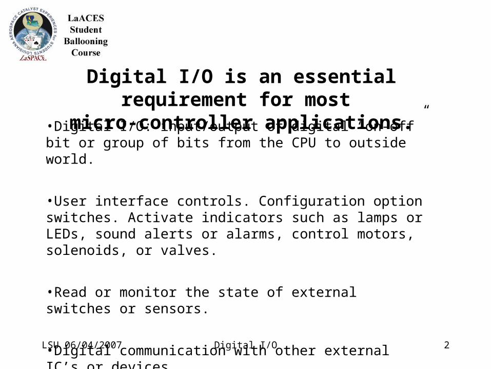
•Digital I/O: input/output of digital “on-off” bit or group of bits from the CPU to outside world.
•User interface controls. Configuration option switches. Activate indicators such as lamps or LEDs, sound alerts or alarms, control motors, solenoids, or valves.
•Read or monitor the state of external switches or sensors.
•Digital communication with other external IC’s or devices.
Digital I/O is an essential requirement for most micro-controller applications.

LSU 06/04/2007 Digital I/O 3
•BASIC Stamp has 16 I/O pins.
•Labeled P0 thru P15. Referenced as pin n in software, where n can be 0 to 15.
•Bi-directional, can be defined in software as inputs or outputs with the INPUT and OUTPUT instructions.

LSU 06/04/2007 Digital I/O 4
•For example, INPUT pin5 defines logical pin5 (or P5) as an output pin. Note that P5 corresponds to physical pin 10 on the actual BASIC Stamp IC. Be sure not confuse logical pins with physical pins.
1

LSU 06/04/2007 Digital I/O 5
Digital I/O pins can be used for connection to external circuits or devices but care must be exercised to avoid damaging or destroying the BASIC Stamp IC.
Observe Electrostatic Discharge precautions, particularly when the BASIC Stamp is not installed on a circuit board or the I/O pins are unconnected (“floating”).
Never connect the pins to voltages outside the range of 0 to 5 volts. Observe polarities!
LSU 06/04/2007 Digital I/O 6
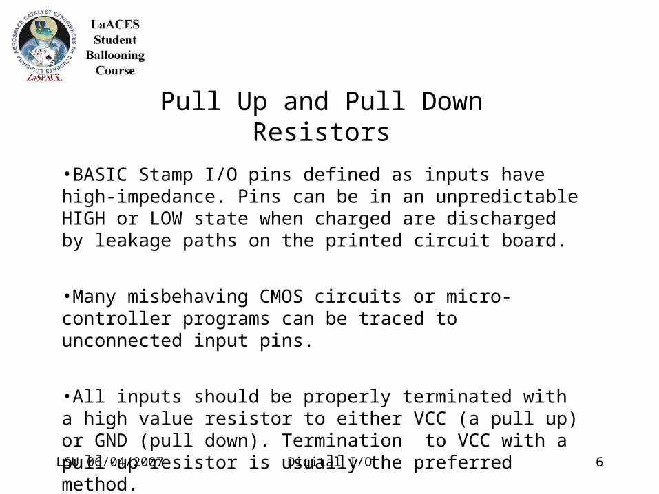
Pull Up and Pull Down Resistors
•BASIC Stamp I/O pins defined as inputs have high-impedance. Pins can be in an unpredictable HIGH or LOW state when charged are discharged by leakage paths on the printed circuit board.
•Many misbehaving CMOS circuits or micro-controller programs can be traced to unconnected input pins.
•All inputs should be properly terminated with a high value resistor to either VCC (a pull up) or GND (pull down). Termination to VCC with a pull up resistor is usually the preferred method.

LSU 06/04/2007 Digital I/O 7
Pull Up and Pull Down Resistors
The resistance value for pullup resistors is not usually critical. 10k ohms is common but can be from 1k to 100k ohms.
With VCC=5V and a pullup resistor of 10k, the maximum current is 500 microamperes or 0.5 ma.
BalloonSat has 10k pullup resistors installed (10-pin SIP).

LSU 06/04/2007 Digital I/O 8
Digital Output•Set the I/O direction for output with the OUTPUT pin instruction.
•A pin configured as an output can be set to a logical high or low state with the HIGH pin or LOW pin instructions.
•A logical LOW is nominally 0 volts.–This state is also called L, 0, off, reset or clear
•A logical HIGH is nominally 5 volts.–This state is also called H, 1, on, set or asserted.
•I/O pins are limited in their current sinking and sourcing ability.
LSU 06/04/2007 Digital I/O 9
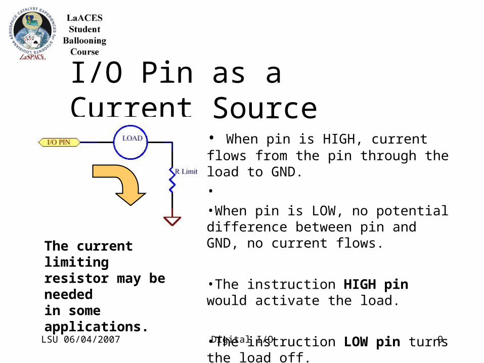
I/O Pin as a Current Source
• When pin is HIGH, current flows from the pin through the load to GND.
•
•When pin is LOW, no potential difference between pin and GND, no current flows.
•The instruction HIGH pin would activate the load.
•The instruction LOW pin turns the load off.
The current limitingresistor may be neededin some applications.

LSU 06/04/2007 Digital I/O 10
I/O Pin as a Current Sink
• When pin is LOW, current flows from the +5V power supply through the load to I/O pin.
• When pin is HIGH, no potential difference between pin and +5V, no current flows.
•The instruction LOW pin would activate the load.
•The instruction HIGH pin turns the load off.
The current limitingresistor may be neededin some applications.

LSU 06/04/2007 Digital I/O 11
Digital Output Applications
Driving an LED with I/O pin as a current source.
Driving an LED with I/O pin as a current sink.
HIGH pin turns LED on. LOW pin turns LED on.
Resistor R limit is chosen to limit current to a safe and appropriate value for the BASIC Stamp IC and the LED.

LSU 06/04/2007 Digital I/O 12
Digital Output Applications
The BASIC Stamp I/O pins have limited current sink and source capability. The pin’s safe voltage limits are 0 to +5V.I/O pins can safely sink or source about 20 mA of current.
For applications requiring higher voltage or current, external buffering is required. The BASIC Stamp can be used to drive bipolar transistors, FETs or solid state or electromechanical relays which in turn can control high current or high voltage circuits.

LSU 06/04/2007 Digital I/O 13
Digital Output ApplicationsBuffered Digital I/O Examples

LSU 06/04/2007 Digital I/O 14
Digital Input•Set the I/O direction for output with the INPUT pin instruction.
•A variable assigned to the I/O pin will take on a value reflecting the voltage level at the pin.
This will work but there is a better way!

LSU 06/04/2007 Digital I/O 15
Common Switch Types:•Normally Open (NO)•Normally Closed (NC)•Toggle•Momentary (Pushbutton)•Rotary
Mechanical switches are not perfect and may exhibit contact bounce as the switch is operated. Typically on the time scale of milliseconds.
Digital I/O: reading a switch

LSU 06/04/2007 Digital I/O 16
Input Interfacing of Electronics to BASIC Stamp

LSU 06/04/2007 Digital I/O 17
Analog I/O with the BASIC Stamp
•The BASIC Stamp’s I/O pins are digital and can only be on or off. The Stamp has no direct ability to read or generate analog voltage levels.
•Additional hardware can be added at a price: $’s and complexity.–Analog-to-Digital Converters (ADC)
–Digital-to-Analog Converters (DAC)
•For simple analog input or output applications, the digital I/O pins and the technique of pulse-width modulation (PWM) can “fake” analog I/O.

LSU 06/04/2007 Digital I/O 18
•A simple Digital-to-Analog Converter can be built with an RC network and a single instruction on the BASIC Stamp.
Analog Output using PWM
•The I/O pin can only be High (+5V) or Low (0 volts) but the RC network will “average” a train pulses to generate an analog voltage.•The PWM instruction is a built-in command to send pulses to the RC network.•Format of the command is
PWM pin, Duty, Duration

LSU 06/04/2007 Digital I/O 19
•Pin selects the desired I/O pin.
•Duty (duty cycle) specifies the ratio of the high pulse duration to the duration of all pulses in a specified interval of time.
•Duration specifies the duration of the PWM pulse train.
Duty is on a scale of 0 to 255, corresponding to 0 to 5 volts. If we wanted an analog voltage output of 2.5 volts,
duty = 255 x 2.5 / 5
duty = 127.5 which we round to the integer 128.
The required Duration is about 5 time-constants of the RC network,
Duration = 5 x 10K x 1 uF
Duration = 0.05 sec or 50 milliseconds
LSU 06/04/2007 Digital I/O 20
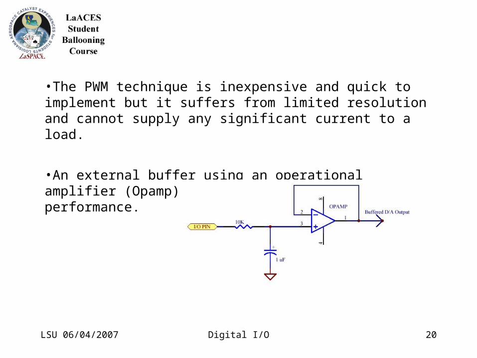
•The PWM technique is inexpensive and quick to implement but it suffers from limited resolution and cannot supply any significant current to a load.
•An external buffer using an operational amplifier (Opamp) can be used to improve performance.

LSU 06/04/2007 Digital I/O 21
Analog Input using PWM
•The BASIC Stamp has no capability for directly reading analog quantities but it does have a specialized instruction RCTIME which allows determining a resistance or capacitance value by measuring the time it takes to charge or discharge an RC network.
•The I/O pin is set to +5v, charging capacitor C. The pin is then changed to an input and a counter measures the time to discharge C through R.
•The 220 ohm resistor limits current from the I/O pin to a safe value.
Circuit for measuring discharge time.
LSU 06/04/2007 Digital I/O 22
Analog Input using PWM
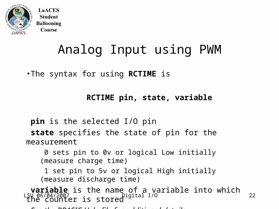
•The syntax for using RCTIME is
RCTIME pin, state, variable
pin is the selected I/O pin
state specifies the state of pin for the measurement 0 sets pin to 0v or logical Low initially (measure charge time)
1 set pin to 5v or logical High initially (measure discharge time)
variable is the name of a variable into which the counter is stored
See the PBASIC Help file for additional details.