LSS Addendum - Hollis · 2424 3 The Explorer 2 LSS combines two previously separate components...
6
LSS Addendum 12-4204 2
Transcript of LSS Addendum - Hollis · 2424 3 The Explorer 2 LSS combines two previously separate components...

N O L I M I T
LSS Addendum
12-4204
2

2 12-4204 r0
DANGERS, WARNINGS, CAUTIONS, AND NOTESPay attention to the following symbols when they appear throughout this docu-ment. They denote important information and tips.
This is the LSS Addendum for the HOLLIS EXPLORER 2
Document # 12-4204
U.S. patents have been applied for; patents pending.
This addendum, specifications and features of the Explorer are proprietary and copyright Hollis Inc., 2016.
This document cannot be copied or distributed without the prior agreement and authorization from Hollis Inc.
All information contained is subject to change. Contact the manufacturer for the latest information. www.hollisgear.com
The EXPLORER is manufactured in the USA by Hollis Inc., 2002 Davis Street, San Leandro, CA 94577. USAPh (510) 729-5100
EC Type approved by SGS UK Ltd. Weston-super-Mare. BS22 6WA. Notified Body No. 0120.
Testing conducted by ANSTI Test Systems. Hants.
To ensure your user information is up to date. Please check www.hollisgear.com/support.asp for updates to this manual.
For warranty information see www.hollisgear.com/support_warranty.asp
WARNINGS: are indicators of important information that if ignored could lead to severe injury or death.
CAUTIONS: are indicators of information that if ignored may lead to minor to moderate injury.
NOTES: indicate tips and advice that can inform of features, aid assem-bly, or prevent damage to the product.
!
312-4204 r0
The Explorer 2 LSS combines two previously separate components found in the Explorer 1 design, the LSS (Life Support System) and the Sensor Array. This design change allows for more robust communications between these two previously separate components, while maintaining the ease of use, cleaning and storage of the Explorer 1 design.

4 12-4204 r0
Fig 1
Fig 2
Fig 3
TEMPSTICK (THERMISTOR ARRAY)
1. The thermistor array is detatchable from the LSS for ease of transport and storage. It connects to the LSS using a 6-pin, keyed Molex® Connector. The male pins are in the thermistor array and the female connector is sealed in the center shaft of the LSS (fig 1).
2. The thermistor array is held in place by one O-Ring which is located in the top groove at the base of the thermistor array (fig 2).
NOTE: Do not put the O-Ring in the bottom groove of the thermistor array. Doing so may make correctly mating the Molex® connectors more difficult.
3. To install the thermistor array, look for the key on the Molex® connector in the LSS. It will look like a small extrusion on the outside of the connector. Line up the keyway on the Molex® connector of the Thermistor array and push down gently on the array until the flange on the array bottoms out on the LSS.
CAUTION: DO NOT use force to mate the array to the LSS. The array should seat quite easily into the LSS. If they are not mating up easily, that probably means you do not have the pieces aligned properly.
OXYGEN SENSORS (3)
3. The three (3) oxygen sensors (PSR-11-39-MD) are mated to the LSS using 3-pin Molex® Connectors. The male connector is in the O2 Sensor and the female connector is in the LSS. You will notice that the female Molex® Connector mounted in the LSS is a half-moon shape. Looking at the male Molex® Connector in the O2 Sensor, you will see a white tab extending from the base of the 3 pins slightly past the end of the 3 pins. The white tab mates to the flat surface of the female Molex® Connector in the LSS.
4. To mount the O2 Sensors in the LSS, line the
512-4204 r0
!
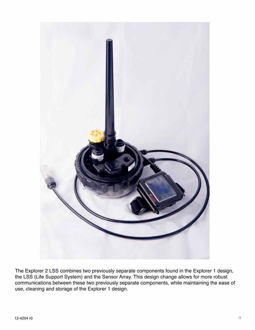
white tab on the sensor up to the flat area on the LSS connector and push down gently until you feel the sensor bottom out on the LSS body (fig 3).
CAUTION: DO NOT twist the sensor into the LSS in an attempt to mate the sensor to the connector in the LSS. Doing so may bend the pins in the O2 Sensor, rendering it unusable. DO NOT attempt to straighten pins that have been bent as that WILL make the sensor unreliable.
WARNING: Using damaged, worn or outdated sensors can lead to serious injury, or even death.
CARBON DIOXIDE SENSOR (CO2 SENSOR)
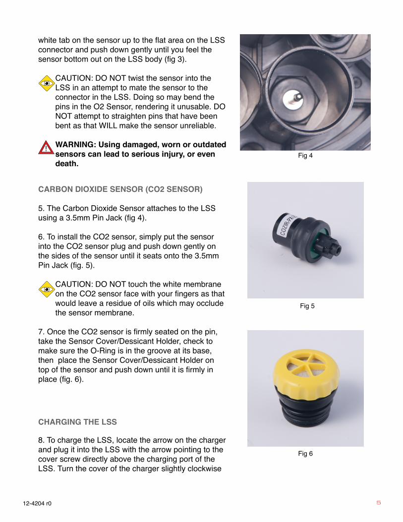
5. The Carbon Dioxide Sensor attaches to the LSS using a 3.5mm Pin Jack (fig 4).
6. To install the CO2 sensor, simply put the sensor into the CO2 sensor plug and push down gently on the sides of the sensor until it seats onto the 3.5mm Pin Jack (fig. 5).
CAUTION: DO NOT touch the white membrane on the CO2 sensor face with your fingers as that would leave a residue of oils which may occlude the sensor membrane.
7. Once the CO2 sensor is firmly seated on the pin, take the Sensor Cover/Dessicant Holder, check to make sure the O-Ring is in the groove at its base, then place the Sensor Cover/Dessicant Holder on top of the sensor and push down until it is firmly in place (fig. 6).
CHARGING THE LSS
8. To charge the LSS, locate the arrow on the charger and plug it into the LSS with the arrow pointing to the cover screw directly above the charging port of the LSS. Turn the cover of the charger slightly clockwise
Fig 4
Fig 5
Fig 6

6 12-4204 r0
Fig 7
to lock the charger onto the charging port of the LSS (fig. 7).
NOTE: If the batteries are fully discharged, the charging light on the LSS may take a few minutes to come on. Leave the LSS charging whenever it is not in use.