LS - Motor Cat_GB
132
LS 3-phase TEFV cage induction motors Aluminium alloy frame - 0.09 to 160 kW Technical catalogue 3676 en - 01.2003 / a
Transcript of LS - Motor Cat_GB
LS3-phase TEFV cage induction motorsAluminium alloy frame - 0.09 to 160 kW
Technical catalogue
3676 en - 01.2003 / a
3-phase TEFV induction motorsLS aluminium alloy frame
0.09 to 160 kW
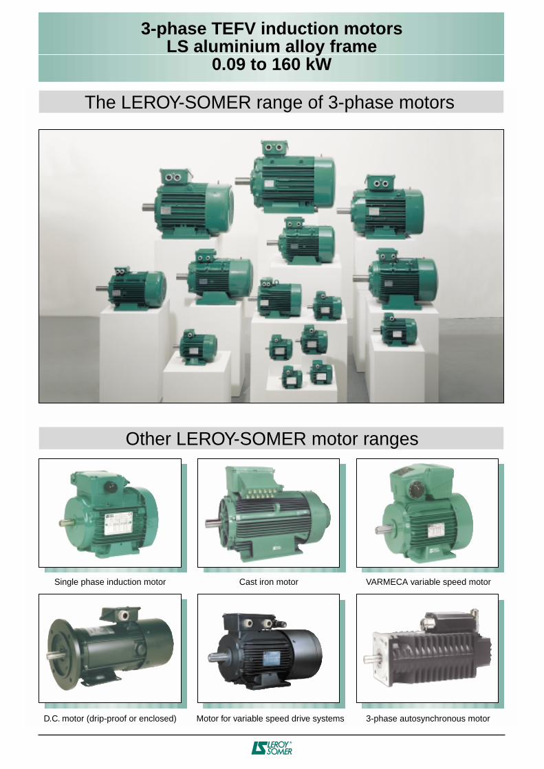
The LEROY-SOMER range of 3-phase motors
Other LEROY-SOMER motor ranges
Single phase induction motor Cast iron motor VARMECA variable speed motor
D.C. motor (drip-proof or enclosed) 3-phase autosynchronous motorMotor for variable speed drive systems
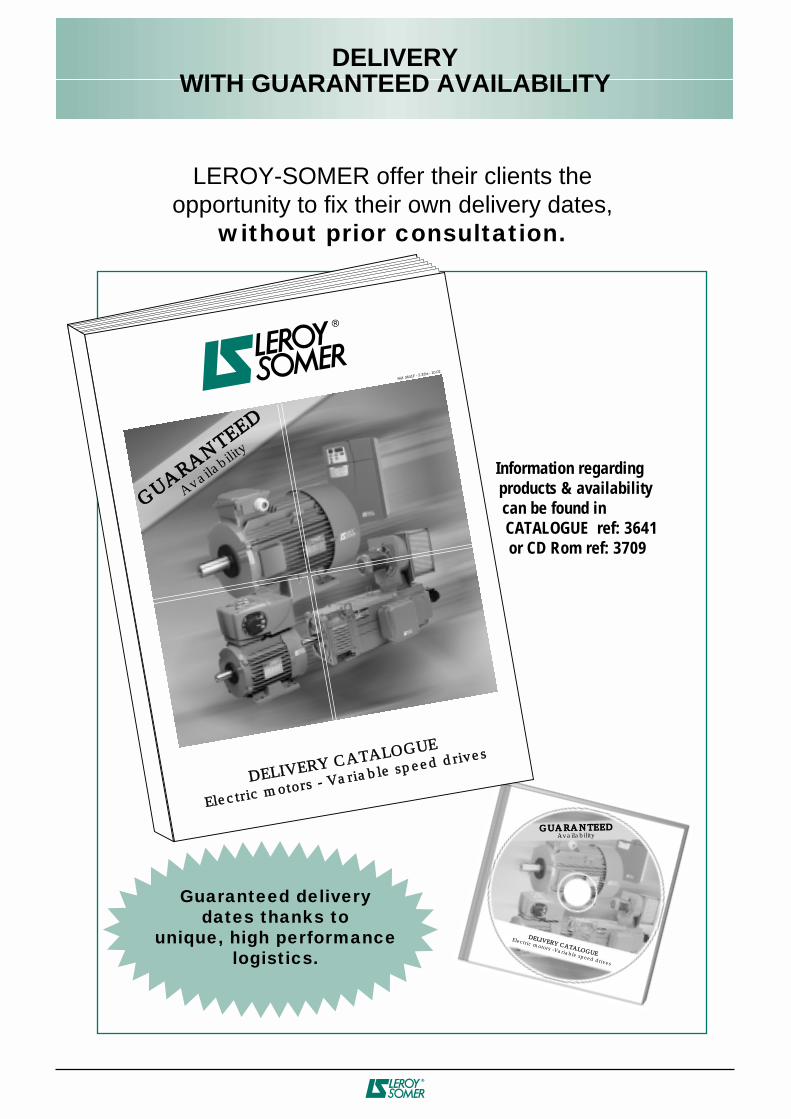
DELIVERYWITH GUARANTEED AVAILABILITY
Information regarding products & availability can be found in CATALOGUE ref: 3641 or CD Rom ref: 3709
GUARANTEEDAvailability
Electric motors -Variable speed drives
DELIVERY CATALOGUE
Réf. 3641F - 2.32/a - 10.02
GUARANTEED
Availabilit
y
Electric motors - Variable speed drivesDELIVERY CATALOGUE
DELIVERY CATALOGUE
Guaranteed deliverydates thanks to
unique, high performance logistics.
LEROY-SOMER offer their clients the opportunity to fix their own delivery dates,
without prior consultation.
2
3-phase TEFV induction motorsLS aluminium alloy frame
0.09 to 160 kW
This document has been translated from the French version which should be used for reference.LEROY-SOMER reserves the right to modify the design, technical specifications and dimensions of the products shown in this catalogue.
The descriptions cannot in any way be considered contractual.
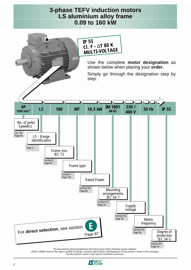
4P1500 min-1 LS 180 MT 18,5 kW IM 1001
IM B3230 /400 V
50 Hz IP 55
No. of polesSpeed(s)
Frame sizeIEC 72
Rated Power
Supplyvoltage
Degree ofprotectionIEC 34-5
LS - Rangeidentification
Frame type
Mountingarrangements
IEC 34-7
Mainsfrequency
IP 55Cl. F - ∆T 80 KMULTI-VOLTAGE
Sec. D5Page 66
Page 3
Section EPage 87
Section FPage 103
Section D4Page 60
Section C2Page 26
Section D2Page 56
Section D2Page 56
Section B1Page 18
For direct selection, see section EPage 87
Use the complete motor designation as shown below when placing your order.
Simply go through the designation step by step.
3-phase TEFV induction motorsLS aluminium alloy frame
0.09 to 160 kW
3
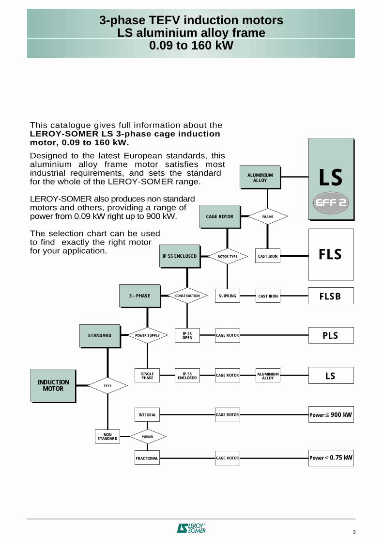
This catalogue gives full information about theLEROY-SOMER LS 3-phase cage inductionmotor, 0.09 to 160 kW.
Designed to the latest European standards, this aluminium alloy frame motor satisfies most industrial requirements, and sets the standard for the whole of the LEROY-SOMER range.
LEROY-SOMER also produces non standard motors and others, providing a range of power from 0.09 kW right up to 900 kW.
The selection chart can be used to find exactly the right motor for your application.
POWER
TYPE
NONSTANDARD
INTEGRAL
FRACTIONAL
POWER SUPPLY
SINGLEPHASE
CONSTRUCTION
IP 23OPEN
ROTOR TYPE
SLIPRING
FRAME
CAST IRON
CAST IRON
IP 55ENCLOSED
ALUMINIUMALLOY
LS
FLS
FLSB
PLS
LS
Power < 0.75 kW
CAGE ROTOR
CAGE ROTOR
CAGE ROTOR
CAGE ROTOR
3 - PHASE
IP 55 ENCLOSED
CAGE ROTOR
ALUMINIUMALLOY
INDUCTIONMOTOR
STANDARD
Power ≤ 900 kW
3-phase TEFV induction motorsLS aluminium alloy frame
4
PAGES
- GENERAL INFORMATION
Quality assurance ............................................................... 7
Standards and approvals................................................... 8
Tolerance of main parameters......................................... 11
Units of measurement and standard formulae .............. 12
Electricity and electromagnetism.............................................. 12
Thermodynamics...................................................................... 13
Noise and vibration................................................................... 13
Dimensions............................................................................... 13
Mechanics ................................................................................ 14
Unit conversions .............................................................. 15
Standard formulae used in electrical engineering ........ 16
Mechanical formulae ................................................................ 16
Electrical formulae .................................................................... 17
- ENVIRONMENT
Definition of “Index of Protection” (IP/IK)....................... 18
Environmental limitations................................................ 19
Normal operating conditions......................................................19
Normal storage conditions.........................................................19
Relative and absolute humidity................................................. 19
Drain holes ............................................................................... 19
Drip cover ..................................................................................19
Impregnation and enhanced protection ......................... 20
Normal atmospheric pressure .................................................. 20
Influence of atmospheric pressure ........................................... 21
Heaters .............................................................................. 22
Space heaters .......................................................................... 22
D.C. injection............................................................................. 22
A.C. injection............................................................................. 22
External finish.................................................................... 23
Interference suppression................................................. 24
PAGES
- CONSTRUCTION
Components ...................................................................... 25
Mounting arrangements............................................................ 26
Mounting arrangements ........................................................... 26
Mountings and positions (IEC standard 60034-7) .................... 27
Bearings and lubrication.................................................. 28
Types of bearing and standard fitting arrangements.................. 28
Bearing assembly diagrams..................................................... 29
Axial loads................................................................................ 30
Permissible axial load (in daN) on main shaft extension for standard bearing assembly ...................................................... 30
Radial loads ............................................................................. 33
Permissible radial load on main shaft extension ...................... 33
Standard mounting................................................................... 34
Types and special fitting arrangements for DE rollerbearings ................................................................................... 37
Bearing assembly diagrams..................................................... 37
Special mounting...................................................................... 38
Bearings and bearing life ......................................................... 40
Lubrication and maintenance of bearings ................................ 41
Lubrication with grease ............................................................ 41
Grease life ................................................................................ 41
Permanently greased bearings ................................................ 41
Bearings without grease nipples .............................................. 42
Bearings with grease nipples ................................................... 42
Special construction and environment ..................................... 42
Cooling method................................................................. 43
Standard codes ........................................................................ 44
Ventilation................................................................................. 45
Motor ventilation ....................................................................... 45
Non-ventilated applications in continuous operation ................ 45
Mains connection...............................................................47
Terminal box............................................................................. 47
Flying leads .............................................................................. 47
Table of terminal boxes and cable glands for rated supply voltage of 400V (according to EN 50262) ............................................. 48
Terminal blocks - Direction of rotation ...................................... 49
Wiring diagrams ....................................................................... 49
Earth terminal ........................................................................... 49
Motor connections............................................................ 50
Contents
Copyright 2003: LEROY-SOMER
3-phase TEFV induction motorsLS aluminium alloy frame
5
PAGES
- OPERATION
Duty cycle - Definitions.................................................... 53
Supply voltage .................................................................. 56
Regulations and standards....................................................... 56Effects on motor performance .................................................. 57Voltage range ........................................................................... 57Simultaneous variation of voltage and frequency ..................... 58Use of 400V - 50 Hz motors on 460V - 60 Hz supplies ..................... 58Use on supplies with U’ voltages different from the voltages in the characteristics tables........................................ 58Phase voltage imbalance ......................................................... 58Phase current imbalance.......................................................... 58
Insulation class - Temperature rise and thermal reserve .. 59
Power - Torque - Efficiency - Power Factor (Cos
ϕ)
....... 60
Definitions................................................................................. 60Efficiency .................................................................................. 60Influence of load on
η
and power factor cos
ϕ
.......................... 60Torque-speed characteristics ................................................... 61Calculation of accelerating torque and starting time .................62Determination of the rated power Pn in relationto duty cycle ... 64General rules for standard motors............................................ 64Determination of the power in intermittent duty cyclesfor adapted motors ................................................................... 64Equivalent thermal constant ..................................................... 64Transient overload after operating in type S1 duty cycle ......... 64Operation of a 3-phase motor from a single-phase ower supply ..................................................................................... 65
Speed of rotation .............................................................. 66
Single fixed speed motor .......................................................... 66High speed motor ..................................................................... 66Low speed motor ...................................................................... 66Multiple fixed speeds motor ...................................................... 66Motor with single winding ......................................................... 66Motor with separate windings ................................................... 66Behaviour of two-speed motors................................................ 67Operating rules ......................................................................... 672-speed motors with connected windings................................. 67Special cases ........................................................................... 68Variable speeds ........................................................................ 68Slip variation at fixed frequency................................................ 68Frequency variation .................................................................. 68
Noise and vibration .......................................................... 71
Motor noise levels..................................................................... 71Noise emitted by rotating machines ......................................... 71Noise levels for machines at full load ....................................... 72Vibration levels - Balancing ...................................................... 73
Performance...................................................................... 75
Thermal protection ................................................................... 75Power factor correction ............................................................. 76Motors operating in parallel ...................................................... 77
PAGES
Starting methods for cage induction motors ................. 78
Motor with associated electronics ............................................ 78Variable speed motor ............................................................... 78
Braking methods............................................................... 82
Operation as an asynchronous generator...................... 84
General .................................................................................... 84Operating characteristics ......................................................... 84Connection to a powerful mains supply ................................... 85Connection - Disconnection ..................................................... 85Reactive power compensation ................................................. 85Electrical protection and safety ................................................ 85Power supply for an isolated network....................................... 85Reactive power compensation ................................................. 85Characteristic curves................................................................ 86Regulation ................................................................................ 86Control and protection.............................................................. 86Performance of motors used as AG ........................................... 86
- ELECTRICAL CHARACTERISTICS
Selection data: single-speed.............................................88Selection data: two-speed................................................ 96
- DIMENSIONS
Dimensions of shaft extensions.....................................104Foot mounted .................................................................. 105Foot and flange mounted .................................................. 106Flange mounted .............................................................. 107Foot and face mounted ....................................................... 108Face mounted.................................................................. 109
- OPTIONAL FEATURES
Non-standard flanges ..................................................... 110
Drip covers ...................................................................... 111
Options ............................................................................ 112
LS motors with optional features ............................................ 112Dimensions of LS motors with optional features .................... 113
Safety options ................................................................. 114
- INSTALLATION AND MAINTENANCE
Voltage drop along cables (standard NFC 15 100) .......... 117Earthing impedance........................................................ 118Packaging weights and dimensions ............................. 119Position of the lifting rings............................................. 120Identification, exploded views and parts list................ 121
Nameplates ............................................................................ 121Frame size: 56 to 132............................................................. 122Frame size: 160 and 180........................................................ 123Frame size: 200 and 225........................................................ 124Frame size: 250 and 280........................................................ 125Frame size: 315...................................................................... 126
Maintenance .....................................................................127
Contents
3-phase TEFV induction motorsLS aluminium alloy frame
6
Index
PAGES
A
FNOR............................................................................... 8Altitude.............................................................................. 19Ambient temperature ........................................................ 19Approvals............................................................................ 8Approvals............................................................................ 9Asynchronous generator .................................................. 84
B
alancing.......................................................................... 73Ball bearings..................................................................... 28Braking ............................................................................. 82
C
able gland ...................................................................... 48Cables ............................................................................ 117Connection ....................................................................... 49Connection ....................................................................... 50Connection diagrams........................................................ 49Cooling ............................................................................. 43Cos
ϕ
(Power Factor)........................................................ 60CSA .................................................................................... 9
D
IGISTART ...................................................................... 78Dimensions..................................................................... 103DIN /VDE............................................................................ 8Direction of rotation .......................................................... 49Drain holes ....................................................................... 19Drip covers ....................................................................... 19Duty types......................................................................... 53
E
arth terminal ................................................................... 49Earthing .......................................................................... 118Efficiency .......................................................................... 60Electrical shaft .................................................................. 77EMC DIRECTIVES ........................................................... 24EN..................................................................................... 10End shields ....................................................................... 25Environment ..................................................................... 19Exploded views............................................................... 122External finish................................................................... 23
F
an cover.......................................................................... 25Flange............................................................................. 106Formulae .......................................................................... 16Frequency variation .......................................................... 68
G
rease.............................................................................. 41Greasing ........................................................................... 41
H
eaters ............................................................................. 22Housing with cooling fins .................................................. 25Humidity............................................................................ 19HYPER CONTROL........................................................... 78
I
dentification ................................................................... 121IEC...................................................................................... 8Impregnation..................................................................... 20Index of protection ............................................................ 18Insulation .......................................................................... 59Insulation class ................................................................. 59Interference suppression .................................................. 24Interference suppression .................................................. 24Intermittent duty................................................................ 64ISO 9001 ............................................................................ 7
J
IS ...................................................................................... 8
K
ey ................................................................................... 73
L
ifting rings..................................................................... 120Locked rotor time.............................................................. 63Lubrication........................................................................ 41
PAGES
M
ains connection.............................................................. 47Maintenance ................................................................... 127Mounting arrangements.................................................... 26Multi-speed motors ........................................................... 66
N
ameplates..................................................................... 121NEMA ................................................................................. 8Noise ................................................................................ 71Noise levels....................................................................... 71Non-ventilated motors....................................................... 46
O
perating positions........................................................... 26Options ........................................................................... 112
P
ackaging ....................................................................... 119Parts list .......................................................................... 122Permissible axial load ....................................................... 30Permissible radial load...................................................... 33Phase imbalance .............................................................. 58Power................................................................................ 60Power Factor (Cos
ϕ
) correction ....................................... 76
Q
uality................................................................................. 7
R
everse-current ................................................................ 82Roller bearings ................................................................. 37Rotor ................................................................................ 25
S
afety.............................................................................. 114Safety options ................................................................. 114Selection data ................................................................... 87Serial number ................................................................. 121Single-speed..................................................................... 87Slip.................................................................................... 68Special fitting arrangement ............................................... 37Speed of rotation .............................................................. 66Standard fitting arrangement ............................................ 34Standards ........................................................................... 8Starting methods .............................................................. 78Starting time ..................................................................... 62Stator ................................................................................ 25Supply voltage .................................................................. 56
T
emperature rise............................................................... 59Terminal blocks ................................................................. 49Terminal box ..................................................................... 47Thermal protection............................................................ 75Thermal reserve ............................................................... 59Tolerance .......................................................................... 11Torque............................................................................... 60Torque curves ................................................................... 61Two-speed motors ............................................................ 87
U
L ....................................................................................... 9UNISTART ........................................................................ 78Unit conversions ............................................................... 15Units.................................................................................. 12UTE..................................................................................... 8
V
ariable speeds ................................................................ 68VARMECA ........................................................................ 78Ventilation ......................................................................... 45Vibration............................................................................ 71Vibration levels.................................................................. 73Voltage drop.................................................................... 117
3-phase TEFV induction motorsLS aluminium alloy frame
General information
7
Industrial concerns are having to copewi th an ever more compet i t i veenvironment. Productivity depends to aconsiderable degree on the rightinvestment at the right time. LEROY-SOMER has the answer,building motors to precise standards ofquality.
When carrying out quality checks on amachine's performance, the first step isto
measure the level of customersatisfaction.
Careful study of this information tells uswhich points need looking at, improvingand monitoring.
From the moment you place your orderwith our administrative staff until themotor is up and running (after designstudies, launch and product ionactivities) we keep you informed andinvolved.
Our own procedures are constantlyunder review. All our staff are involvedin both operational process analysisand continuous training programmes.These initiatives help them serve youbetter, and increased skills bringincreased motivation.
At LEROY-SOMER, we think it vital forour customers to know the importancewe attach to quality.
LEROY-SOMER has entrusted thecertification of its expertise to variousinternational organizations.Certification is granted by indepen-dent professional auditors, and rec-ognises the high standards of the
company's quality assurance pro-cedures.
All activities resulting in the final ver-sion of the machine have thereforereceived official ISO 9000 accre-ditation. Products are alsoapproved by official bo-dies who inspect theirtechnical performancewith regard to the var-ious standards.This is a fundamentalrequirement for a com-pany of internationalstanding.
A1 - Quality assurance
8
3-phase TEFV induction motorsLS aluminium alloy frame
General information
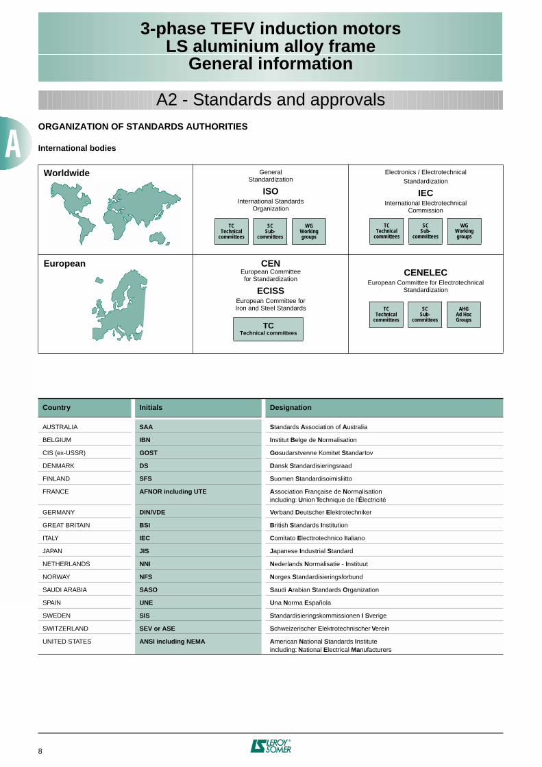
ORGANIZATION OF STANDARDS AUTHORITIES
International bodies
Worldwide
GeneralStandardization
ISO
International StandardsOrganization
Electronics / ElectrotechnicalStandardization
IEC
International ElectrotechnicalCommission
European CEN
European Committeefor Standardization
ECISS
European Committee forIron and Steel Standards
CENELEC
European Committee for ElectrotechnicalStandardization
Country Initials Designation
AUSTRALIA
SAA S
tandards
A
ssociation of
A
ustralia
BELGIUM
IBN I
nstitut
B
elge de
N
ormalisation
CIS (ex-USSR)
GOST Go
sudarstvenne Komitet
St
andartov
DENMARK
DS D
ansk
S
tandardisieringsraad
FINLAND
SFS S
uomen
S
tandardisoimisliitto
FRANCE
AFNOR including UTE A
ssociation
F
rançaise de
N
ormalisationincluding:
U
nion
T
echnique de l'
É
lectricité
GERMANY
DIN/VDE V
erband
D
eutscher
E
lektrotechniker
GREAT BRITAIN
BSI B
ritish
S
tandards
I
nstitution
ITALY
IEC C
omitato
E
lecttrotechnico
I
taliano
JAPAN
JIS J
apanese
I
ndustrial
S
tandard
NETHERLANDS
NNI N
ederlands
N
ormalisatie -
I
nstituut
NORWAY
NFS N
orges
S
tandardisieringsforbund
SAUDI ARABIA
SASO S
audi
A
rabian
S
tandards
O
rganization
SPAIN
UNE U
na
N
orma
E
spañola
SWEDEN
SIS S
tandardisieringskommissionen
I
S
verige
SWITZERLAND
SEV or ASE S
chweizerischer
E
lektrotechnischer
V
erein
UNITED STATES
ANSI including NEMA A
merican
N
ational
S
tandards
I
nstituteincluding:
N
ational
E
lectrical
Ma
nufacturers
A2 - Standards and approvals
TCTechnical
committees
SCSub-
committees
WGWorkinggroups
TCTechnical
committees
SCSub-
committees
WGWorkinggroups
TCTechnical
committees
SCSub-
committees
AHGAd HocGroups
TC
Technical committees
3-phase TEFV induction motorsLS aluminium alloy frame
General information
9
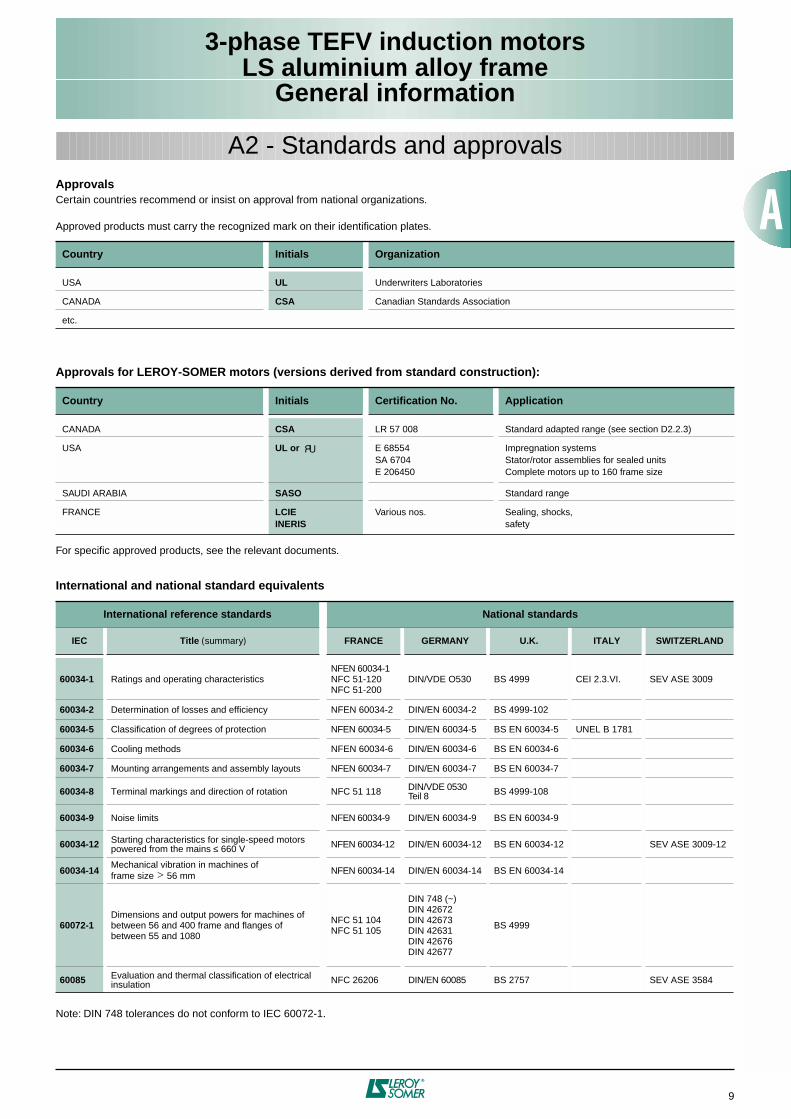
Approvals
Certain countries recommend or insist on approval from national organizations.
Approved products must carry the recognized mark on their identification plates.
Approvals for LEROY-SOMER motors (versions derived from standard construction):
For specific approved products, see the relevant documents.
International and national standard equivalents
Note: DIN 748 tolerances do not conform to IEC 60072-1.
Country Initials Organization
USA
UL
Underwriters Laboratories
CANADA
CSA
Canadian Standards Association
etc.
Country Initials Certification No. Application
CANADA
CSA
LR 57 008 Standard adapted range (see section D2.2.3)
USA
UL or
E 68554SA 6704E 206450
Impregnation systemsStator/rotor assemblies for sealed unitsComplete motors up to 160 frame size
SAUDI ARABIA
SASO
Standard range
FRANCE
LCIEINERIS
Various nos. Sealing, shocks,safety
International reference standards National standards
IEC Title
(
summary
)
FRANCE GERMANY U.K. ITALY SWITZERLAND
60034-1
Ratings and operating characteristicsNFEN 60034-1NFC 51-120NFC 51-200
DIN/VDE O530 BS 4999 CEI 2.3.VI. SEV ASE 3009
60034-2
Determination of losses and efficiency NFEN 60034-2 DIN/EN 60034-2 BS 4999-102
60034-5
Classification of degrees of protection NFEN 60034-5 DIN/EN 60034-5 BS EN 60034-5 UNEL B 1781
60034-6
Cooling methods NFEN 60034-6 DIN/EN 60034-6 BS EN 60034-6
60034-7
Mounting arrangements and assembly layouts NFEN 60034-7 DIN/EN 60034-7 BS EN 60034-7
60034-8
Terminal markings and direction of rotation NFC 51 118 DIN/VDE 0530Teil 8 BS 4999-108
60034-9
Noise limits NFEN 60034-9 DIN/EN 60034-9 BS EN 60034-9
60034-12
Starting characteristics for single-speed motorspowered from the mains
≤
660 V NFEN 60034-12 DIN/EN 60034-12 BS EN 60034-12 SEV ASE 3009-12
60034-14
Mechanical vibration in machines offrame size
>
56 mm NFEN 60034-14 DIN/EN 60034-14 BS EN 60034-14
60072-1
Dimensions and output powers for machines of between 56 and 400 frame and flanges of between 55 and 1080
NFC 51 104NFC 51 105
DIN 748 (~)DIN 42672DIN 42673DIN 42631DIN 42676DIN 42677
BS 4999
60085
Evaluation and thermal classification of electrical insulation NFC 26206 DIN/EN 60085 BS 2757 SEV ASE 3584
A2 - Standards and approvals
10
3-phase TEFV induction motorsLS aluminium alloy frame
General information
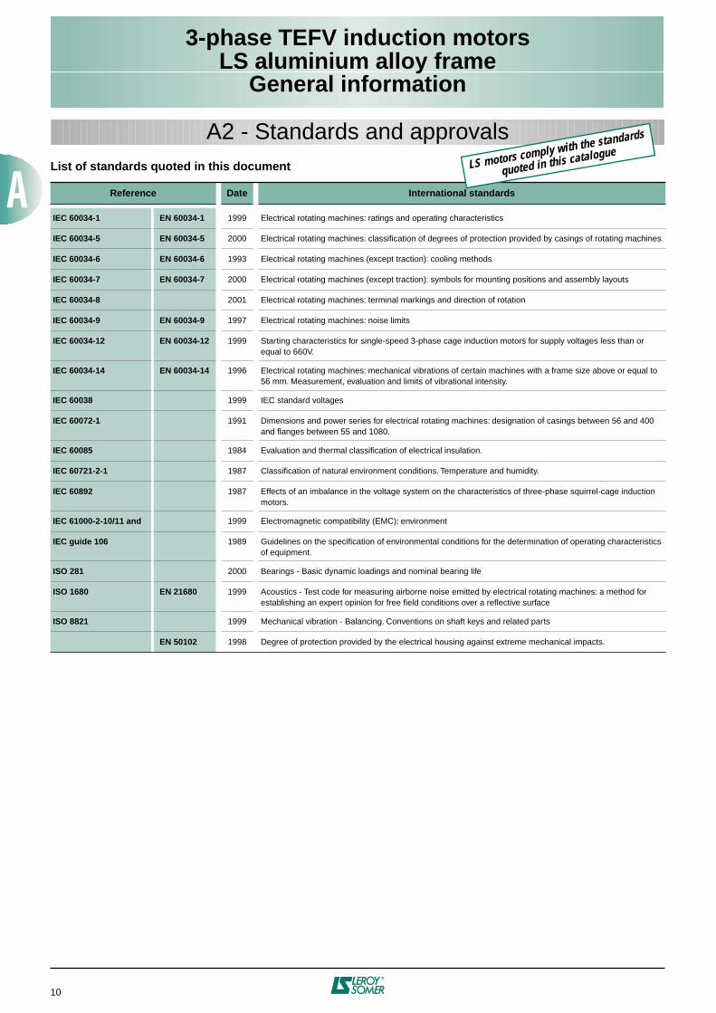
List of standards quoted in this document
Reference Date International standards
IEC 60034-1 EN 60034-1
1999 Electrical rotating machines: ratings and operating characteristics
IEC 60034-5 EN 60034-5
2000 Electrical rotating machines: classification of degrees of protection provided by casings of rotating machines.
IEC 60034-6 EN 60034-6
1993 Electrical rotating machines (except traction): cooling methods
IEC 60034-7 EN 60034-7
2000 Electrical rotating machines (except traction): symbols for mounting positions and assembly layouts
IEC 60034-8
2001 Electrical rotating machines: terminal markings and direction of rotation
IEC 60034-9 EN 60034-9
1997 Electrical rotating machines: noise limits
IEC 60034-12 EN 60034-12
1999 Starting characteristics for single-speed 3-phase cage induction motors for supply voltages less than or equal to 660V.
IEC 60034-14 EN 60034-14
1996 Electrical rotating machines: mechanical vibrations of certain machines with a frame size above or equal to 56 mm. Measurement, evaluation and limits of vibrational intensity.
IEC 60038
1999 IEC standard voltages
IEC 60072-1
1991 Dimensions and power series for electrical rotating machines: designation of casings between 56 and 400 and flanges between 55 and 1080.
IEC 60085
1984 Evaluation and thermal classification of electrical insulation.
IEC 60721-2-1
1987 Classification of natural environment conditions. Temperature and humidity.
IEC 60892
1987 Effects of an imbalance in the voltage system on the characteristics of three-phase squirrel-cage induction motors.
IEC 61000-2-10/11 and
1999 Electromagnetic compatibility (EMC): environment
IEC guide 106
1989 Guidelines on the specification of environmental conditions for the determination of operating characteristics of equipment.
ISO 281
2000 Bearings - Basic dynamic loadings and nominal bearing life
ISO 1680 EN 21680
1999 Acoustics - Test code for measuring airborne noise emitted by electrical rotating machines: a method for establishing an expert opinion for free field conditions over a reflective surface
ISO 8821
1999 Mechanical vibration - Balancing. Conventions on shaft keys and related parts
EN 50102
1998 Degree of protection provided by the electrical housing against extreme mechanical impacts.
A2 - Standards and approvals
LS motors comply with the standards
quoted in this catalogue
3-phase TEFV induction motorsLS aluminium alloy frame
General information
11
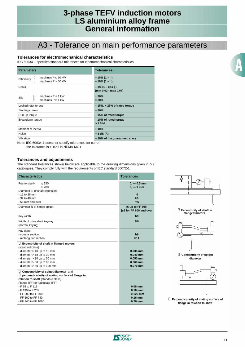
Tolerances for electromechanical characteristics
IEC 60034-1 specifies standard tolerances for electromechanical characteristics.
Note: IEC 60034-1 does not specify tolerances for current the tolerance is ± 10% in NEMA-MG1
Tolerances and adjustments
The standard tolerances shown below are applicable to the drawing dimensions given in ourcatalogues. They comply fully with the requirements of IEC standard 60072-1.
Parameters Tolerances
Efficiency machines P
≤
50 kWmachines P > 50 kW
– 15% (1 –
η
)– 10% (1 –
η
)
Cos
ϕ
– 1/6 (1 – cos
ϕ
)(min 0.02 - max 0.07)
Slip machines P < 1 kWmachines P
≥
1 kW
± 30%± 20%
Locked rotor torque
– 15%, + 25% of rated torque
Starting current
+ 20%
Run-up torque
– 15% of rated torque
Breakdown torque
– 10% of rated torque> 1.5 M
N
Moment of inertia ± 10%
Noise + 3 dB (A)
Vibration + 10% of the guaranteed class
Characteristics Tolerances
Frame size H ≤ 250≥ 280
Diameter ∅ of shaft extension:- 11 to 28 mm- 32 to 48 mm- 55 mm and over
0, — 0.5 mm0, — 1 mm
j6k6m6
Diameter N of flange spigot j6 up to FF 500,js6 for FF 600 and over
Key width h9
Width of drive shaft keyway(normal keying)
N9
Key depth- square section- rectangular section
h9h11
➀ Eccentricity of shaft in flanged motors(standard class)- diameter > 10 up to 18 mm- diameter > 18 up to 30 mm- diameter > 30 up to 50 mm- diameter > 50 up to 80 mm- diameter > 80 up to 120 mm
0.035 mm0.040 mm0.050 mm0.060 mm0.070 mm
➁ Concentricity of spigot diameter and➂ perpendicularity of mating surface of flange in relation to shaft (standard class)Flange (FF) or Faceplate (FT):- F 55 to F 115- F 130 to F 265- FF 300 to FF 500- FF 600 to FF 740- FF 940 to FF 1080
0.08 mm0.10 mm
0.125 mm0.16 mm0.20 mm
A3 - Tolerance on main performance parameters
E/2
10
10
➀ Eccentricity of shaft inflanged motors
➁ Concentricity of spigotdiameter
➂ Perpendicularity of mating surface of flange in relation to shaft
12
3-phase TEFV induction motorsLS aluminium alloy frame
General information
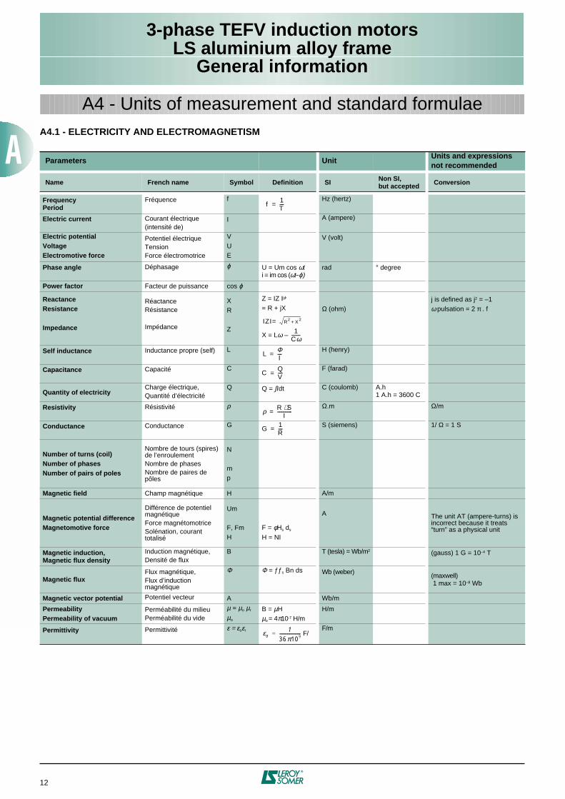
A4 - Units of measurement and standard formulaeA4.1 - ELECTRICITY AND ELECTROMAGNETISM
Parameters UnitUnits and expressionsnot recommended
Name French name Symbol Definition SI Non SI,but accepted Conversion
FrequencyPeriod
Fréquence
f
Hz (hertz)
Electric current Courant électrique(intensité de)
I
A (ampere)
Electric potentialVoltageElectromotive force
Potentiel électriqueTensionForce électromotrice
VUE
V (volt)
Phase angle
Déphasage
ϕ
U = Um cos ωti = im cos (ωt–ϕ)
rad
° degree
Power factor Facteur de puissance cos ϕ
ReactanceResistance
Impedance
RéactanceRésistance
Impédance
XR
Z
Z = IZ Ijϕ
= R + jX
X = Lω –
Ω (ohm)j is defined as j2 = –1ω pulsation = 2 π . f
Self inductance
Inductance propre (self)
L
H (henry)
Capacitance
Capacité
C
F (farad)
Quantity of electricityCharge électrique,Quantité d’électricité
Q
Q = ∫Idt
C (coulomb)
A.h1 A.h = 3600 C
Resistivity
Résistivité
ρ
Ω.m
Ω/m
Conductance
Conductance
G
S (siemens)
1/ Ω = 1 S
Number of turns (coil)Number of phasesNumber of pairs of poles
Nombre de tours (spires) de l’enroulementNombre de phasesNombre de paires de pôles
N
mp
Magnetic field Champ magnétique H A/m
Magnetic potential differenceMagnetomotive force
Différence de potentiel magnétiqueForce magnétomotriceSolénation, courant totalisé
Um
F, FmH
F = φHs ds
H = NI
A The unit AT (ampere-turns) is incorrect because it treats “turn” as a physical unit
Magnetic induction,Magnetic flux density
Induction magnétique,Densité de flux
B
T (tesla) = Wb/m2
(gauss) 1 G = 10–4 T
Magnetic fluxFlux magnétique,Flux d’induction magnétique
Φ
Φ = ƒƒs Bn ds Wb (weber)
(maxwell) 1 max = 10–8 Wb
Magnetic vector potential Potentiel vecteur A Wb/m
PermeabilityPermeability of vacuum
Perméabilité du milieuPerméabilité du vide
µ = µo µr
µo
B = µHµo = 4π10-7 H/m
H/m
Permittivity
Permittivité ε = εoεrF/
F/m
f1T----=
IZI R2
X2
+=
1Cω--------
LΦI----=
CQV----=
ρ R S⋅I
-------------=
G1R----=
εo1
36π109-------------------=
3-phase TEFV induction motorsLS aluminium alloy frame
General information
13
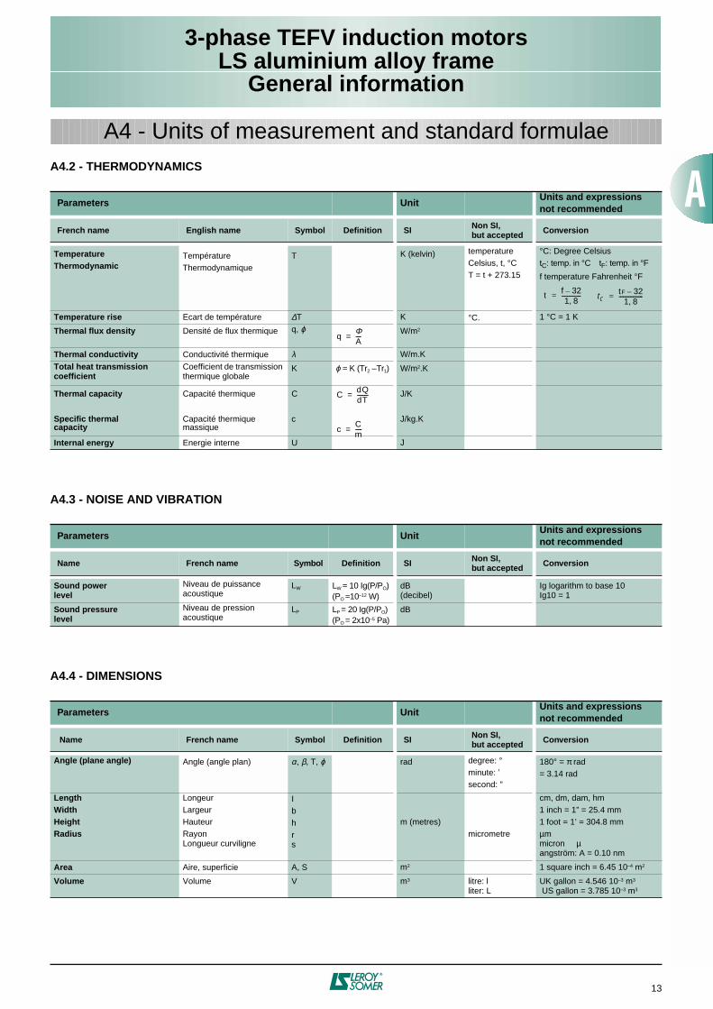
A4 - Units of measurement and standard formulaeA4.2 - THERMODYNAMICS
A4.3 - NOISE AND VIBRATION
A4.4 - DIMENSIONS
Parameters UnitUnits and expressionsnot recommended
French name English name Symbol Definition SI Non SI,but accepted Conversion
TemperatureThermodynamic
TempératureThermodynamique
T
K (kelvin) temperatureCelsius, t, °CT = t + 273.15
°C: Degree CelsiustC: temp. in °C tF: temp. in °F
f temperature Fahrenheit °F
Temperature rise Ecart de température ∆T K °C. 1 °C = 1 K
Thermal flux density
Densité de flux thermique
q, ϕ
W/m2
Thermal conductivity Conductivité thermique λ W/m.K
Total heat transmission coefficient
Coefficient de transmission thermique globale
K
ϕ = K (Tr2 –Tr1) W/m2.K
Thermal capacity
Specific thermalcapacity
Capacité thermique
Capacité thermique massique
C
c
J/K
J/kg.K
Internal energy Energie interne U J
Parameters UnitUnits and expressionsnot recommended
Name French name Symbol Definition SI Non SI,but accepted Conversion
Sound powerlevel
Niveau de puissance acoustique
LW
LW = 10 Ig(P/PO)(PO =10–12 W)
dB(decibel)
Ig logarithm to base 10Ig10 = 1
Sound pressurelevel
Niveau de pression acoustique
LP
LP = 20 Ig(P/PO)(PO = 2x10⁻⁵ Pa)
dB
Parameters UnitUnits and expressionsnot recommended
Name French name Symbol Definition SI Non SI,but accepted Conversion
Angle (plane angle)
Angle (angle plan)
α, β, T, ϕ
rad degree: °minute: ’second: ”
180° = π rad= 3.14 rad
LengthWidthHeightRadius
LongeurLargeurHauteurRayonLongueur curviligne
Ibhrs
m (metres)
micrometre
cm, dm, dam, hm 1 inch = 1” = 25.4 mm1 foot = 1’ = 304.8 mmµmmicron µangström: A = 0.10 nm
Area Aire, superficie A, S m2 1 square inch = 6.45 10–4 m2
Volume
Volume
V
m3
litre: lliter: L
UK gallon = 4.546 10–3 m3
US gallon = 3.785 10–3 m3
t f 32–1 8,
--------------= tCtF 32–
1 8,-----------------=
qΦA----=
CdQdT--------=
cCm-----=
14
3-phase TEFV induction motorsLS aluminium alloy frame
General information
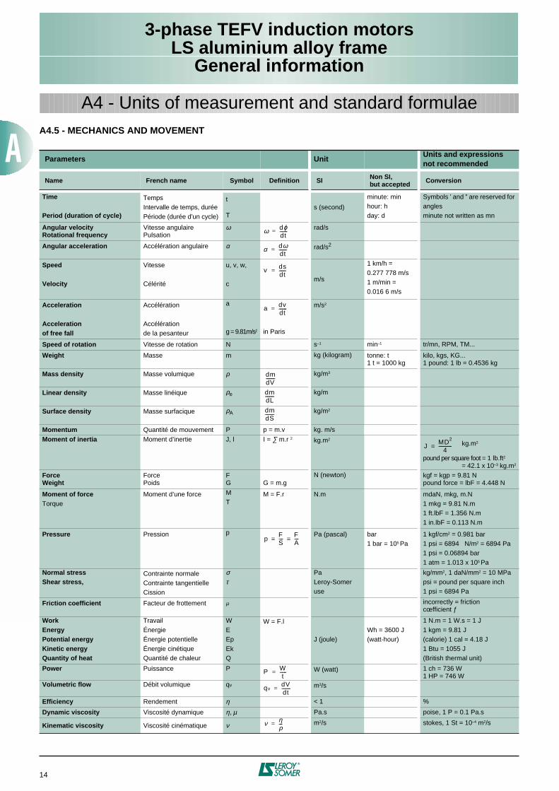
A4 - Units of measurement and standard formulaeA4.5 - MECHANICS AND MOVEMENT
Parameters UnitUnits and expressionsnot recommended
Name French name Symbol Definition SI Non SI,but accepted Conversion
Time
Period (duration of cycle)
TempsIntervalle de temps, durée Période (durée d’un cycle)
t
T
s (second)
minute: minhour: hday: d
Symbols ’ and ” are reserved for anglesminute not written as mn
Angular velocityRotational frequency
Vitesse angulairePulsation
ω
rad/s
Angular acceleration Accélération angulaire
α
rad/s2
Speed Velocity
Vitesse Célérité
u, v, w,
cm/s
1 km/h =0.277 778 m/s1 m/min =0.016 6 m/s
Acceleration Accelerationof free fall
Accélération Accélérationde la pesanteur
a
g = 9.81m/s2 in Paris
m/s2
Speed of rotation Vitesse de rotation N s–1 min–1 tr/mn, RPM, TM...
Weight Masse
m
kg (kilogram) tonne: t1 t = 1000 kg
kilo, kgs, KG...1 pound: 1 lb = 0.4536 kg
Mass density Masse volumique
ρ
kg/m3
Linear density Masse linéique
ρe
kg/m
Surface density Masse surfacique
ρA
kg/m2
Momentum Quantité de mouvement P p = m.v kg. m/s
Moment of inertia
Moment d’inertie
J, l I = ∑ m.r 2 kg.m2 kg.m2
pound per square foot = 1 lb.ft2 = 42.1 x 10⁻³ kg.m2
ForceWeight
ForcePoids
FG G = m.g
N (newton) kgf = kgp = 9.81 Npound force = lbF = 4.448 N
Moment of forceTorque
Moment d’une force
MT
M = F.r N.m mdaN, mkg, m.N1 mkg = 9.81 N.m1 ft.lbF = 1.356 N.m1 in.lbF = 0.113 N.m
Pressure
Pression
p Pa (pascal) bar1 bar = 105 Pa
1 kgf/cm2 = 0.981 bar1 psi = 6894 N/m2 = 6894 Pa1 psi = 0.06894 bar1 atm = 1.013 x 10⁵ Pa
Normal stressShear stress,
Contrainte normaleContrainte tangentielleCission
στ
PaLeroy-Somer use
kg/mm2, 1 daN/mm2 = 10 MPapsi = pound per square inch1 psi = 6894 Pa
Friction coefficient Facteur de frottement
µ
incorrectly = frictioncœfficient ƒ
WorkEnergyPotential energyKinetic energy Quantity of heat
TravailÉnergieÉnergie potentielleÉnergie cinétiqueQuantité de chaleur
WEEpEk Q
W = F.l
J (joule)Wh = 3600 J(watt-hour)
1 N.m = 1 W.s = 1 J1 kgm = 9.81 J(calorie) 1 cal = 4.18 J1 Btu = 1055 J (British thermal unit)
Power Puissance
P
W (watt) 1 ch = 736 W1 HP = 746 W
Volumetric flow Débit volumique
qv
m3/s
Efficiency Rendement η < 1 %
Dynamic viscosity Viscosité dynamique η, µ Pa.s poise, 1 P = 0.1 Pa.s
Kinematic viscosity Viscosité cinématique ν m2/s stokes, 1 St = 10–4 m2/s
ω dϕdt-------=
α dωdt-------=
v dsdt------=
a dvdt-------=
dmdV--------
dmdL--------
dmdS--------
JMD2
4------------=
pFS----
FA----= =
P Wt
------=
qvdVdt--------=
ν ηρ---=
3-phase TEFV induction motorsLS aluminium alloy frame
General information
15
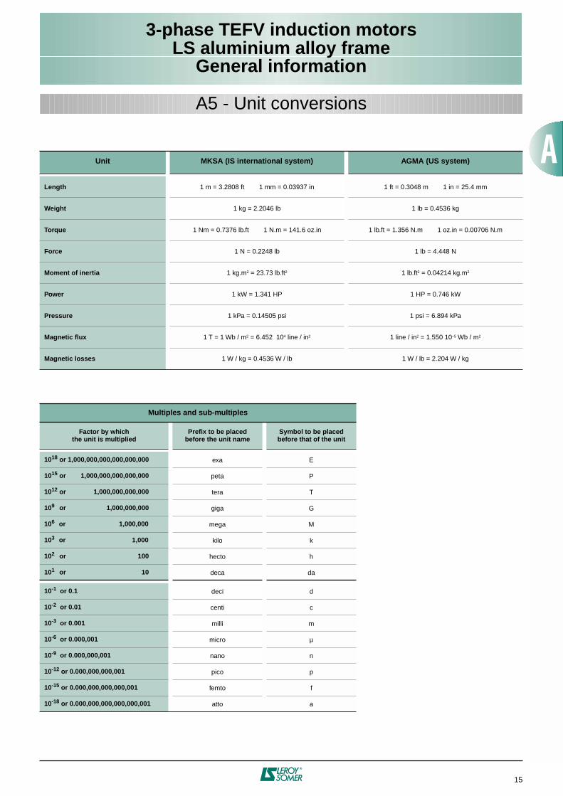
A5 - Unit conversions
Unit MKSA (IS international system) AGMA (US system)
Length 1 m = 3.2808 ft 1 mm = 0.03937 in 1 ft = 0.3048 m 1 in = 25.4 mm
Weight 1 kg = 2.2046 lb 1 lb = 0.4536 kg
Torque 1 Nm = 0.7376 lb.ft 1 N.m = 141.6 oz.in 1 lb.ft = 1.356 N.m 1 oz.in = 0.00706 N.m
Force 1 N = 0.2248 lb 1 lb = 4.448 N
Moment of inertia 1 kg.m2 = 23.73 lb.ft2 1 lb.ft2 = 0.04214 kg.m2
Power 1 kW = 1.341 HP 1 HP = 0.746 kW
Pressure 1 kPa = 0.14505 psi 1 psi = 6.894 kPa
Magnetic flux 1 T = 1 Wb / m2 = 6.452 104 line / in2 1 line / in2 = 1.550 10–5 Wb / m2
Magnetic losses 1 W / kg = 0.4536 W / lb 1 W / lb = 2.204 W / kg
Multiples and sub-multiples
Factor by whichthe unit is multiplied
Prefix to be placedbefore the unit name
Symbol to be placedbefore that of the unit
1018 or 1,000,000,000,000,000,000 exa E
1015 or 1,000,000,000,000,000 peta P
1012 or 1,000,000,000,000 tera T
109 or 1,000,000,000 giga G
106 or 1,000,000 mega M
103 or 1,000 kilo k
102 or 100 hecto h
101 or 10 deca da
10-1 or 0.1 deci d
10-2 or 0.01 centi c
10-3 or 0.001 milli m
10-6 or 0.000,001 micro µ
10-9 or 0.000,000,001 nano n
10-12 or 0.000,000,000,001 pico p
10-15 or 0.000,000,000,000,001 femto f
10-18 or 0.000,000,000,000,000,001 atto a
16
3-phase TEFV induction motorsLS aluminium alloy frame
General information
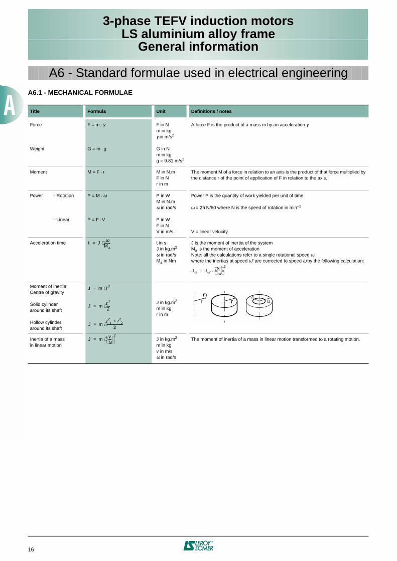
A6 - Standard formulae used in electrical engineeringA6.1 - MECHANICAL FORMULAE
Title Formula Unit Definitions / notes
Force
Weight
F = m . γ
G = m . g
F in Nm in kgγ in m/s2
G in Nm in kgg = 9.81 m/s2
A force F is the product of a mass m by an acceleration γ
Moment M = F . r M in N.mF in Nr in m
The moment M of a force in relation to an axis is the product of that force multiplied by the distance r of the point of application of F in relation to the axis.
Power - Rotation
- Linear
P = M . ω
P = F . V
P in WM in N.mω in rad/s
P in WF in NV in m/s
Power P is the quantity of work yielded per unit of time
ω = 2π N/60 where N is the speed of rotation in min–1
V = linear velocity
Acceleration time t in sJ in kg.m2
ω in rad/sMa in Nm
J is the moment of inertia of the systemMa is the moment of accelerationNote: all the calculations refer to a single rotational speed ωwhere the inertias at speed ω’’ are corrected to speed ω by the following calculation:
Moment of inertiaCentre of gravity
Solid cylinderaround its shaft
Hollow cylinderaround its shaft
J in kg.m2
m in kgr in m
Inertia of a massin linear motion
J in kg.m2
m in kgv in m/sω in rad/s
The moment of inertia of a mass in linear motion transformed to a rotating motion.
t Jω
Ma--------⋅=
Jω Jω′ω′ω------
⋅2
=
J m r 2⋅=
J mr 2
2-----⋅=
J mr2
1 r22+
2---------------------⋅=
r1r2rr
m
J mvω----
2⋅=
3-phase TEFV induction motorsLS aluminium alloy frame
General information
17
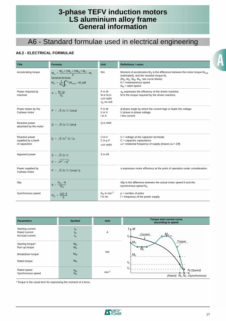
A6 - Standard formulae used in electrical engineeringA6.2 - ELECTRICAL FORMULAE
* Torque is the usual term for expressing the moment of a force.
Title Formula Unit Definitions / notes
Accelerating torque
General formula:
Nm Moment of acceleration MA is the difference between the motor torque Mmot (estimated), and the resistive torque Mr.(MD, MA, MM, MN, see curve below)N = instantaneous speedNN = rated speed
Power required bymachine
P in WM in N.mω in rad/sηA no unit
ηA expresses the efficiency of the driven machine.M is the torque required by the driven machine.
Power drawn by the3-phase motor
P in WU in VI in A
ϕ phase angle by which the current lags or leads the voltage.U phase to phase voltage.I line current.
Reactive powerabsorbed by the motor
Q in VAR
Reactive powersupplied by a bankof capacitors
U in VC in µ F
ω in rad/s
U = voltage at the capacitor terminalsC = capacitor capacitanceω = rotational frequency of supply phases (ω = 2πf)
Apparent power S in VA
Power supplied by3-phase motor
η expresses motor efficiency at the point of operation under consideration.
Slip Slip is the difference between the actual motor speed N and the synchronous speed NS
Synchronous speed NS in min-1
f in Hzp = number of polesf = frequency of the power supply
Parameters Symbol Unit Torque and current curveaccording to speed
Starting currentRated currentNo-load current
IDINIO
A
Starting torque*Run up torque
Breakdown torque
Rated torque
MDMA
MM
MN
Nm
Rated speedSynchronous speed
NNNS
min-1
MaMD 2MA 2MM MN+ + +
6------------------------------------------------------------ Mr–=
Ma1
NN-------- Mmot M r–( ) Nd
0
NN∫=
P M ω⋅ηA
--------------=
P 3 U I ϕcos⋅ ⋅ ⋅=
Q 3 U I ϕsin⋅ ⋅ ⋅=
Q 3 U2 C ω⋅ ⋅ ⋅=
S 3 U I⋅ ⋅=
S P2 Q2+=
P 3 U I ϕ η⋅cos⋅ ⋅ ⋅=
gNS N–
NS------------------=
NS120 f⋅
p-----------------=
I M
ID
MD
MN
IN
IO
MA
MM
NN NS
N
Current
(Rated)
Torque
(Speed)
(Synchronous)
3-phase TEFV induction motorsLS aluminium alloy frame
Environment
18
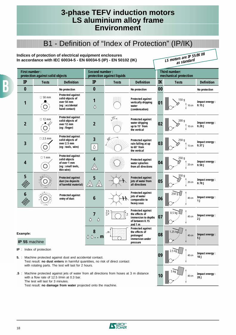
Indices of protection of electrical equipment enclosuresIn accordance with IEC 60034-5 - EN 60034-5 (IP) - EN 50102 (IK)
IP0
1
2
3
4
5
IP IK
∅ 50 mm
∅ 12 mm
∅ 2.5 mm
∅ 1 mm
0 00
1
15°
2
3
4
60°
5
6
7
8 ..m
0,15
m
1 m
01
02
03
05
07
09
150 g
10 cm
250 g
15 cm
250 g
20 cm
250 g40 cm
0.5 kg40 cm
2.5 kg40 cm
. . m
6
200 g
10 cm
350 g
20 cm
04
06
081.25 kg
40 cm
105 kg
40 cm
Tests Definition Tests Definition Tests Definition
First number :protection against solid objects
Third number:mechanical protection
No protection
Protected againstsolid objects ofover 12 mm(eg : finger)
Protected againstsolid objects of over 50 mm(eg : accidentalhand contact)
Protected againstsolid objects ofover 2.5 mm(eg : tools, wire)
Protected againstsolid objectsof over 1 mm(eg : small tools, thin wire)
Second number :protection against liquids
No protection
Protected againstdust (no depositsof harmful material)
Protected againstthe effects of prolonged immersion underpressure
Protected againstthe effects of immersion to depths of between 0.15 and 1 m
Protected againstjets of watercomparable to heavy seas
Protected againstjets of water fromall directions
Protected againstwater splashesfrom all directions
Protected againstrain falling at up to 60° from the vertical
Protected againstwater drippingup to 15° fromthe vertical
Protected againstvertically drippingwater(condensation)
Impact energy :0.15 J
Impact energy :0.20 J
Impact energy :0.37 J
Impact energy :0.70 J
Impact energy :2 J
Impact energy :10 J
Impact energy :20 J
Impact energy :5 J
Impact energy :1 J
Impact energy :0.50 J
No protection
Protected againstentry of dust
Example:
IP 55 machine
IP : Index of protection
5. : Machine protected against dust and accidental contact.Test result: no dust enters in harmful quantities, no risk of direct contactwith rotating parts. The test will last for 2 hours.
.5 : Machine protected against jets of water from all directions from hoses at 3 m distancewith a flow rate of 12.5 l/min at 0.3 bar.The test will last for 3 minutes.Test result: no damage from water projected onto the machine.
B1 - Definition of “Index of Protection” (IP/IK)
LS motors are IP 55/IK 08
as standard
3-phase TEFV induction motorsLS aluminium alloy frame
Environment
19
B2 - Environmental limitations
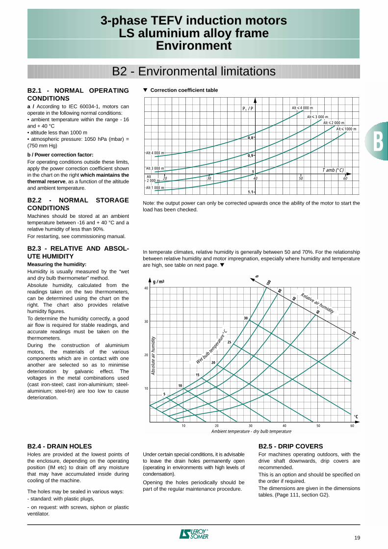
B2.1 - NORMAL OPERATINGCONDITIONS
a /
According to IEC 60034-1, motors canoperate in the following normal conditions:• ambient temperature within the range - 16and + 40 °C• altitude less than 1000 m• atmospheric pressure: 1050 hPa (mbar) =(750 mm Hg)
b / Power correction factor:
For operating conditions outside these limits,apply the power correction coefficient shownin the chart on the right
which maintains thethermal reserve
, as a function of the altitudeand ambient temperature.
B2.2 - NORMAL STORAGECONDITIONS
Machines should be stored at an ambienttemperature between -16 and + 40 °C and arelative humidity of less than 90%.For restarting, see commissioning manual.
B2.3 - RELATIVE AND ABSOL-UTE HUMIDITY
Measuring the humidity:
Humidity is usually measured by the “wetand dry bulb thermometer” method.Absolute humidity, calculated from thereadings taken on the two thermometers,can be determined using the chart on theright. The chart also provides relativehumidity figures.To determine the humidity correctly, a goodair flow is required for stable readings, andaccurate readings must be taken on thethermometers.During the construction of aluminiummotors, the materials of the variouscomponents which are in contact with oneanother are selected so as to minimisedeterioration by galvanic effect. Thevoltages in the metal combinations used(cast iron-steel; cast iron-aluminium; steel-aluminium; steel-tin) are too low to causedeterioration.
Correction coefficient table
Note: the output power can only be corrected upwards once the ability of the motor to start theload has been checked.
In temperate climates, relative humidity is generally between 50 and 70%. For the relationshipbetween relative humidity and motor impregnation, especially where humidity and temperatureare high, see table on next page.
Alt 1000 m
Alt 2 000 m Alt 3 000 m
Alt 4 000 m
Alt 1 000 m
1
P1 / P
20 605030 40
1.1
0,8
0,9Alt 4 000 m
Alt 3 000 m T amb (°C)Alt2 000 m
10
Ambient temperature - dry bulb temperature
Abso
lute
air
hum
idity
20 30 40 50 60
10
20
30
40
5
10
15
20
25
30
Wet bulbtem
perat
ur
e °C
°C
g / m3
20
40
60
80
100
%
Relative air humidity
B2.4 - DRAIN HOLES
Holes are provided at the lowest points ofthe enclosure, depending on the operatingposition (IM etc) to drain off any moisturethat may have accumulated inside duringcooling of the machine.
The holes may be sealed in various ways:- standard: with plastic plugs,
- on request: with screws, siphon or plasticventilator.
Under certain special conditions, it is advisableto leave the drain holes permanently open(operating in environments with high levels ofcondensation).
Opening the holes periodically should bepart of the regular maintenance procedure.
B2.5 - DRIP COVERS
For machines operating outdoors, with thedrive shaft downwards, drip covers arerecommended.This is an option and should be specified onthe order if required.The dimensions are given in the dimensionstables. (Page 111, section G2).
3-phase TEFV induction motorsLS aluminium alloy frame
Environment
20
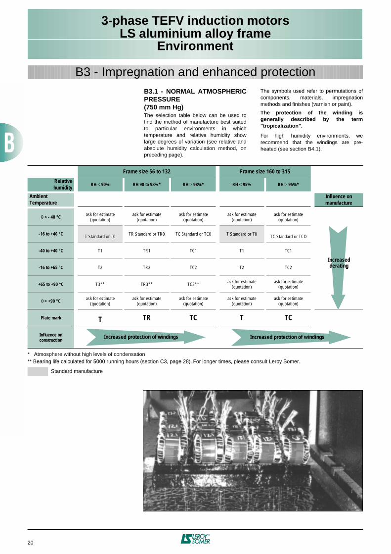
B3.1 - NORMAL ATMOSPHERICPRESSURE (750 mm Hg)
The selection table below can be used tofind the method of manufacture best suitedto particular environments in whichtemperature and relative humidity showlarge degrees of variation (see relative andabsolute humidity calculation method, onpreceding page).
The symbols used refer to permutations ofcomponents, materials, impregnationmethods and finishes (varnish or paint).
The protection of the winding isgenerally described by the term"tropicalization".
For high humidity environments, werecommend that the windings are pre-heated (see section B4.1).
B3 - Impregnation and enhanced protection
* Atmosphere without high levels of condensation** Bearing life calculated for 5000 running hours (section C3, page 28). For longer times, please consult Leroy Somer.
Standard manufacture
Frame size 56 to 132 Frame size 160 to 315
Relativehumidity
RH
<
90% RH 90 to 98%* RH
>
98%* RH
≤
95% RH
>
95%*
AmbientTemperature
Influence onmanufacture
θ
< - 40 °C
ask for estimate (quotation)
ask for estimate (quotation)
ask for estimate (quotation)
ask for estimate (quotation)
ask for estimate (quotation)
-16 to +40 °C
T Standard or T0 TR Standard or TR0 TC Standard or TC0 T Standard or T0 TC Standard or TCO
-40 to +40 °C
T1 TR1 TC1 T1 TC1
-16 to +65 °C
T2 TR2 TC2 T2 TC2
+65 to +90 °C
T3** TR3** TC3** ask for estimate (quotation)
ask for estimate (quotation)
θ
> +90 °C
ask for estimate (quotation)
ask for estimate (quotation)
ask for estimate (quotation)
ask for estimate (quotation)
ask for estimate (quotation)
Plate mark
T TR TC T TC
Influence onconstruction
Increasedderating
Increased protection of windings Increased protection of windings
3-phase TEFV induction motorsLS aluminium alloy frame
Environment
21
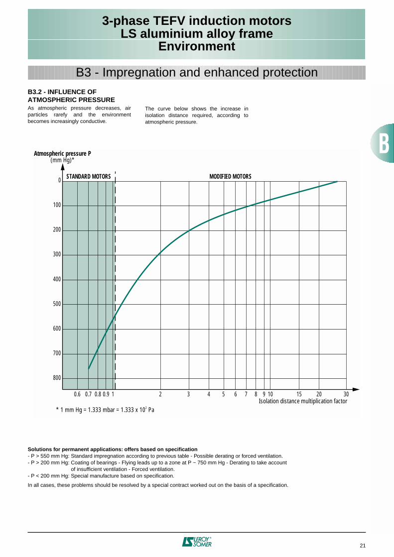
B3.2 - INFLUENCE OF ATMOSPHERIC PRESSURE
As atmospheric pressure decreases, airparticles rarefy and the environmentbecomes increasingly conductive.
The curve below shows the increase inisolation distance required, according toatmospheric pressure.
B3 - Impregnation and enhanced protection
0.6 0.7 0.8 0.9 1 2 3 4 5 6 7 8 9 10 15 20 30
800
700
600
500
400
300
200
100
0
Isolation distance multiplication factor
STANDARD MOTORS MODIFIED MOTORS
Atmospheric pressure P(mm Hg)*
* 1 mm Hg = 1.333 mbar = 1.333 x 10² Pa
Solutions for permanent applications: offers based on specification
- P > 550 mm Hg: Standard impregnation according to previous table - Possible derating or forced ventilation.- P > 200 mm Hg: Coating of bearings - Flying leads up to a zone at P ~ 750 mm Hg - Derating to take account
of insufficient ventilation - Forced ventilation.- P < 200 mm Hg: Special manufacture based on specification.
In all cases, these problems should be resolved by a special contract worked out on the basis of a specification.
3-phase TEFV induction motorsLS aluminium alloy frame
Environment
22
B4.1 - SPACE HEATERS
Severe climatic conditions, e.g.
T
amb < - 40°C, RH > 95% etc, may require the use of spaceheaters (fitted to the motor windings) which serve to maintain the average temperature of themotor, provide trouble-free starting, and eliminate problems caused by condensation (loss ofinsulation).
The heater supply wires are brought out to a terminal block in the motor terminal box. Theheaters must be switched off while the motor is running.
The space heaters use 200/240V, single-phase, 50 or 60 Hz.
B4.2 - D.C. INJECTION
An alternative to the use of space heaters is to inject direct current into two of the phases wiredin series from a D.C. voltage source which can give the total power indicated in the table above.This method can only be used on motors of less than 10 kW.
This is easily calculated: if R is the resistance of the windings in series, the D.C. voltage will begiven by the equation (Ohm’s law):
Resistance should be measured with a micro-ohmmeter.
B4.3 - A.C. INJECTION
A single-phase A.C. voltage (from 10 to 15% of rated voltage), can be used between 2 phasesplaced in series.
This method can be used on the whole LS range.
Motor type No. of poles Power: P(W)
LS 80
2 - 4 - 6 - 8 10
LS 90 to LS 132
2 - 4 - 6 - 8 25
LS 160 to LS 180
2 - 4 - 6 - 8 50
LS 200 to LS 225
2 - 4 - 6 - 8 50
LS 250
24 - 6 - 8
5080
LS 280 to LS 315
24 - 6 - 8
80100
U V( ) P W( ) R Ω( )⋅=
B4 - Heaters
3-phase TEFV induction motorsLS aluminium alloy frame
Environment
23
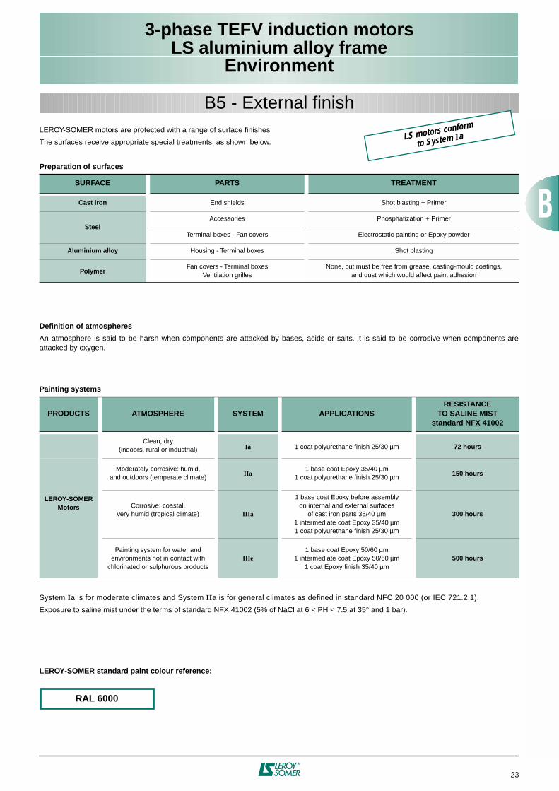
B5 - External finish
LEROY-SOMER motors are protected with a range of surface finishes.
The surfaces receive appropriate special treatments, as shown below.
Preparation of surfaces
Definition of atmospheres
An atmosphere is said to be harsh when components are attacked by bases, acids or salts. It is said to be corrosive when components areattacked by oxygen.
Painting systems
System
I
a is for moderate climates and System
II
a is for general climates as defined in standard NFC 20 000 (or IEC 721.2.1).
Exposure to saline mist under the terms of standard NFX 41002 (5% of NaCl at 6 < PH < 7.5 at 35° and 1 bar).
LEROY-SOMER standard paint colour reference:
SURFACE PARTS TREATMENT
Cast iron
End shields Shot blasting + Primer
Steel
Accessories Phosphatization + Primer
Terminal boxes - Fan covers Electrostatic painting or Epoxy powder
Aluminium alloy
Housing - Terminal boxes Shot blasting
Polymer
Fan covers - Terminal boxesVentilation grilles
None, but must be free from grease, casting-mould coatings,and dust which would affect paint adhesion
PRODUCTS ATMOSPHERE SYSTEM APPLICATIONSRESISTANCE
TO SALINE MISTstandard NFX 41002
Clean, dry(indoors, rural or industrial)
Ia
1 coat polyurethane finish 25/30
µ
m
72 hours
LEROY-SOMERMotors
Moderately corrosive: humid,and outdoors (temperate climate)
IIa
1 base coat Epoxy 35/40
µ
m1 coat polyurethane finish 25/30
µ
m
150 hours
Corrosive: coastal,very humid (tropical climate)
IIIa
1 base coat Epoxy before assemblyon internal and external surfaces
of cast iron parts 35/40
µ
m1 intermediate coat Epoxy 35/40
µ
m1 coat polyurethane finish 25/30
µ
m
300 hours
Painting system for water andenvironments not in contact with
chlorinated or sulphurous products
IIIe
1 base coat Epoxy 50/60
µ
m1 intermediate coat Epoxy 50/60
µ
m1 coat Epoxy finish 35/40
µ
m
500 hours
RAL 6000
LS motors conform
to System Ia
3-phase TEFV induction motorsLS aluminium alloy frame
Environment
24
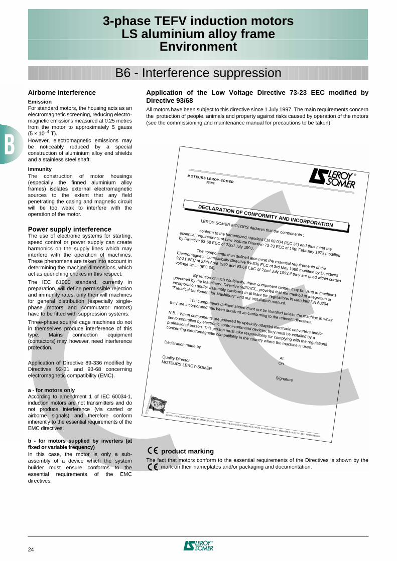
LEROY-SOMER MOTORS declares that the components :conform to the harmonized standard EN 60 034 (IEC 34) and thus meet the
essential requirements of Low Voltage Directive 73-23 EEC of 19th February 1973 modified
by Directive 93-68 EEC of 22nd July 1993.The components thus defined also meet the essential requirements of the
Electromagnetic Compatibility Directive 89-336 EEC of 3rd May 1989 modified by Directives
92-31 EEC of 28th April 1992 and 93-68 EEC of 22nd July 1993,if they are used within certain
voltage limits (IEC 34).
By reason of such conformity, these component ranges may be used in machines
governed by the Machinery Directive 98/37/CE, provided that the method of integration or
incorporation and/or assembly conforms to at least the regulations in standard EN 60204
"Electrical Equipment for Machinery" and our installation manual.The components defined above must not be installed unless the machine in which
they are incorporated has been declared as conforming to the relevant directives.
N.B. : When components are powered by specially adapted electronic converters and/or
servo-controlled by electronic control-command devices, they must be installed by a
professional person. This person must take responsibility for complying with the regulations
concerning electromagnetic compatibility in the country where the machine is used.Declaration made by At
On
Quality DirectorMOTEURS LEROY-SOMER Signature
MOTEURS LEROY-SOMERUSINE
DECLARATION OF CONFORMITY AND INCORPORATION
MOTEURS LEROY-SOMER (SIEGE SOCIAL BD MARCELLIN LEROY - 16015 ANGOULEME CEDEX) SOCIETE ANONYME AU CAPITAL DE 411 800 000 F - RCS ANGOULEME B 338 567 258 - SIRET 338 567 258 00011
B6 - Interference suppression
Application of the Low Voltage Directive 73-23 EEC modified byDirective 93/68
All motors have been subject to this directive since 1 July 1997. The main requirements concernthe protection of people, animals and property against risks caused by operation of the motors(see the commissioning and maintenance manual for precautions to be taken).
product marking
The fact that motors conform to the essential requirements of the Directives is shown by the mark on their nameplates and/or packaging and documentation.
Airborne interference
Emission
For standard motors, the housing acts as anelectromagnetic screening, reducing electro-magnetic emissions measured at 0.25 metresfrom the motor to approximately 5 gauss(5
×
10
–4
T).However, electromagnetic emissions maybe noticeably reduced by a specialconstruction of aluminium alloy end shieldsand a stainless steel shaft.
Immunity
The construction of motor housings(especially the finned aluminium alloyframes) isolates external electromagneticsources to the extent that any fieldpenetrating the casing and magnetic circuitwill be too weak to interfere with theoperation of the motor.
Power supply interference
The use of electronic systems for starting,speed control or power supply can createharmonics on the supply lines which mayinterfere with the operation of machines.These phenomena are taken into account indetermining the machine dimensions, whichact as quenching chokes in this respect.
The IEC 61000 standard, currently inpreparation, will define permissible rejectionand immunity rates: only then will machinesfor general distribution (especially single-phase motors and commutator motors)have to be fitted with suppression systems.
Three-phase squirrel cage machines do notin themselves produce interference of thistype. Mains connection equipment(contactors) may, however, need interferenceprotection.
Application of Directive 89-336 modified byDirectives 92-31 and 93-68 concerningelectromagnetic compatibility (EMC).
a - for motors only
According to amendment 1 of IEC 60034-1,induction motors are not transmitters and donot produce interference (via carried orairborne signals) and therefore conforminherently to the essential requirements of theEMC directives.
b - for motors supplied by inverters (atfixed or variable frequency)
In this case, the motor is only a sub-assembly of a device which the systembuilder must ensure conforms to theessential requirements of the EMCdirectives.
3-phase TEFV induction motorsLS aluminium alloy frame
Construction
25
10
7
4
5
3
2
1 9
86
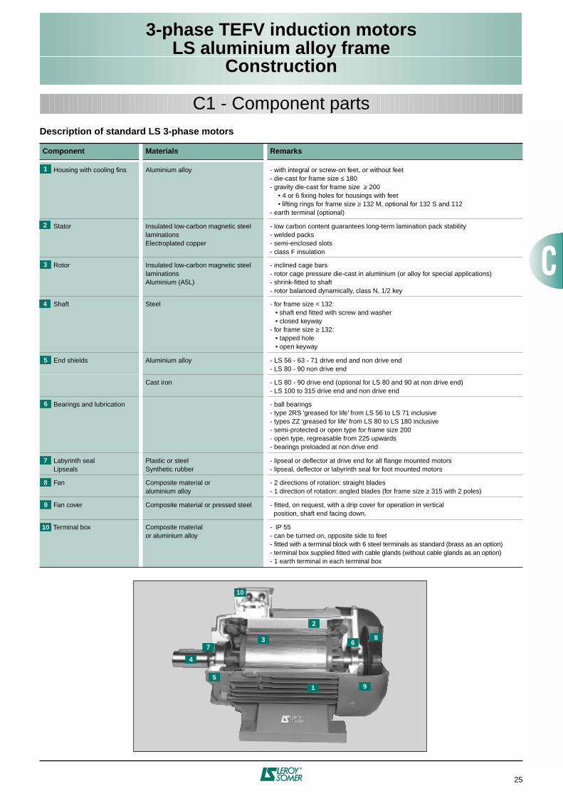
Description of standard LS 3-phase motors
Component Materials Remarks
Housing with cooling fins Aluminium alloy - with integral or screw-on feet, or without feet- die-cast for frame size
≤
180- gravity die-cast for frame size
≥
200• 4 or 6 fixing holes for housings with feet• lifting rings for frame size
≥
132 M, optional for 132 S and 112- earth terminal (optional)
Stator Insulated low-carbon magnetic steellaminationsElectroplated copper
- low carbon content guarantees long-term lamination pack stability- welded packs- semi-enclosed slots- class F insulation
Rotor Insulated low-carbon magnetic steel laminationsAluminium (A5L)
- inclined cage bars- rotor cage pressure die-cast in aluminium (or alloy for special applications)- shrink-fitted to shaft- rotor balanced dynamically, class N, 1/2 key
Shaft Steel - for frame size
<
132:• shaft end fitted with screw and washer• closed keyway
- for frame size
≥
132:• tapped hole• open keyway
End shields Aluminium alloy - LS 56 - 63 - 71 drive end and non drive end- LS 80 - 90 non drive end
Cast iron - LS 80 - 90 drive end (optional for LS 80 and 90 at non drive end)- LS 100 to 315 drive end and non drive end
Bearings and lubrication - ball bearings- type 2RS ‘greased for life’ from LS 56 to LS 71 inclusive- types ZZ ‘greased for life’ from LS 80 to LS 180 inclusive- semi-protected or open type for frame size 200- open type, regreasable from 225 upwards- bearings preloaded at non drive end
Labyrinth seal Lipseals
Plastic or steelSynthetic rubber
- lipseal or deflector at drive end for all flange mounted motors- lipseal, deflector or labyrinth seal for foot mounted motors
Fan Composite material or aluminium alloy
- 2 directions of rotation: straight blades- 1 direction of rotation: angled blades (for frame size
≥
315 with 2 poles)
Fan cover Composite material or pressed steel - fitted, on request, with a drip cover for operation in vertical position, shaft end facing down.
Terminal box Composite materialor aluminium alloy
- IP 55
-
can be turned on, opposite side to feet- fitted with a terminal block with 6 steel terminals as standard (brass as an option)
-
terminal box supplied fitted with cable glands (without cable glands as an option)- 1 earth terminal in each terminal box
1
C1 - Component parts
1
2
3
4
5
6
7
8
9
10
3-phase TEFV induction motorsLS aluminium alloy frame
Construction
26
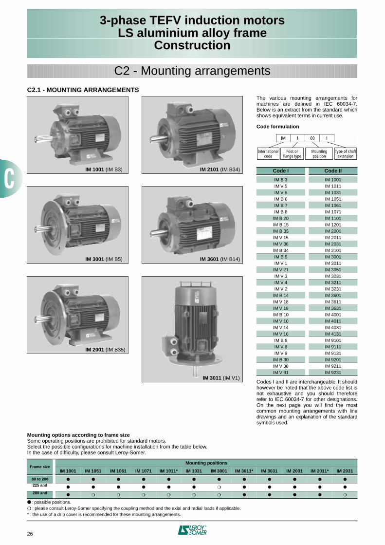
The various mounting arrangements formachines are defined in IEC 60034-7.Below is an extract from the standard whichshows equivalent terms in current use.
Code formulation
Codes I and II are interchangeable. It shouldhowever be noted that the above code list isnot exhaustive and you should thereforerefer to IEC 60034-7 for other designations.On the next page you will find the mostcommon mounting arrangements with linedrawings and an explanation of the standardsymbols used.
IM 1001 (IM B3)
IM 3001 (IM B5)
IM 2001 (IM B35)
IM 2101 (IM B34)
IM 3601 (IM B14)
IM 3011 (IM V1)
Code I Code II
IM B 3 IM 1001IM V 5 IM 1011IM V 6 IM 1031IM B 6 IM 1051IM B 7 IM 1061IM B 8 IM 1071IM B 20 IM 1101IM B 15 IM 1201IM B 35 IM 2001IM V 15 IM 2011IM V 36 IM 2031IM B 34 IM 2101IM B 5 IM 3001IM V 1 IM 3011IM V 21 IM 3051IM V 3 IM 3031IM V 4 IM 3211IM V 2 IM 3231
IM B 14 IM 3601IM V 18 IM 3611IM V 19 IM 3631IM B 10 IM 4001IM V 10 IM 4011IM V 14 IM 4031IM V 16 IM 4131IM B 9 IM 9101IM V 8 IM 9111IM V 9 IM 9131
IM B 30 IM 9201IM V 30 IM 9211IM V 31 IM 9231
IM
Internationalcode
Type of shaftextension
Foot orflange type
Mountingposition
1 00 1
C2 - Mounting arrangements
Mounting options according to frame size
Some operating positions are prohibited for standard motors.Select the possible configurations for machine installation from the table below.In the case of difficulty, please consult Leroy-Somer.
: possible positions.
: please consult Leroy-Somer specifying the coupling method and the axial and radial loads if applicable.* : the use of a drip cover is recommended for these mounting arrangements.
Frame size
Mounting positions
IM 1001 IM 1051 IM 1061 IM 1071 IM 1011* IM 1031 IM 3001 IM 3011* IM 3031 IM 2001 IM 2011* IM 2031
80 to 200
225 and
280 and
C2.1 - MOUNTING ARRANGEMENTS
3-phase TEFV induction motorsLS aluminium alloy frame
Construction
27
C2 - Mounting arrangements
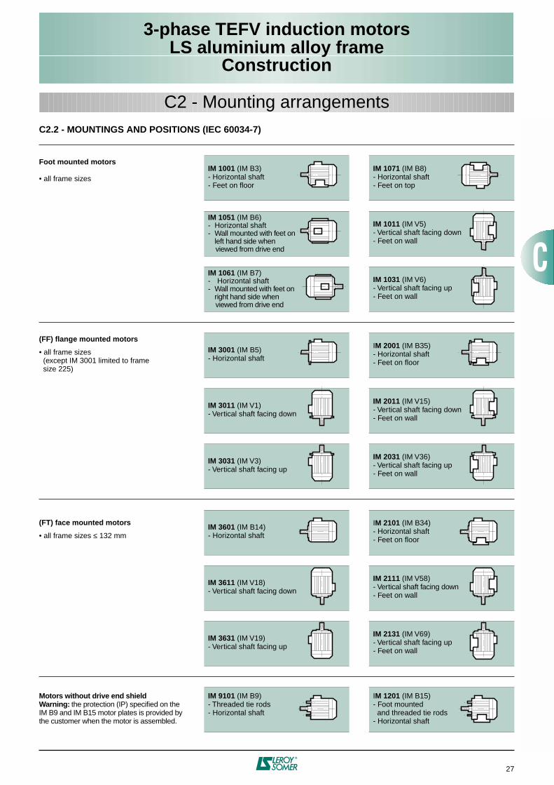
C2.2 - MOUNTINGS AND POSITIONS (IEC 60034-7)
Foot mounted motors
• all frame sizes
IM 1001
(IM B3)- Horizontal shaft- Feet on floor
IM 1071
(IM B8)- Horizontal shaft- Feet on top
IM 1051
(IM B6)- Horizontal shaft- Wall mounted with feet on
left hand side when viewed from drive end
IM 1011
(IM V5)- Vertical shaft facing down- Feet on wall
IM 1061
(IM B7)- Horizontal shaft- Wall mounted with feet on
right hand side when viewed from drive end
IM 1031
(IM V6)- Vertical shaft facing up- Feet on wall
(FF) flange mounted motors
• all frame sizes (except IM 3001 limited to frame size 225)
IM 3001
(IM B5)- Horizontal shaft
I
M 2001
(IM B35)- Horizontal shaft- Feet on floor
IM 3011
(IM V1)- Vertical shaft facing down
IM 2011
(IM V15)- Vertical shaft facing down- Feet on wall
IM 3031
(IM V3)- Vertical shaft facing up
IM 2031
(IM V36)- Vertical shaft facing up- Feet on wall
(FT) face mounted motors
• all frame sizes
≤
132 mm
IM 3601
(IM B14)- Horizontal shaft
I
M 2101
(IM B34)- Horizontal shaft- Feet on floor
IM 3611
(IM V18)- Vertical shaft facing down
IM 2111
(IM V58)- Vertical shaft facing down- Feet on wall
IM 3631
(IM V19)- Vertical shaft facing up
IM 2131
(IM V69)- Vertical shaft facing up- Feet on wall
Motors without drive end shieldWarning:
the protection (IP) specified on the IM B9 and IM B15 motor plates is provided by the customer when the motor is assembled.
IM 9101
(IM B9)- Threaded tie rods- Horizontal shaft
I
M 1201
(IM B15)- Foot mounted and threaded tie rods- Horizontal shaft
3-phase TEFV induction motorsLS aluminium alloy frame
Construction
28
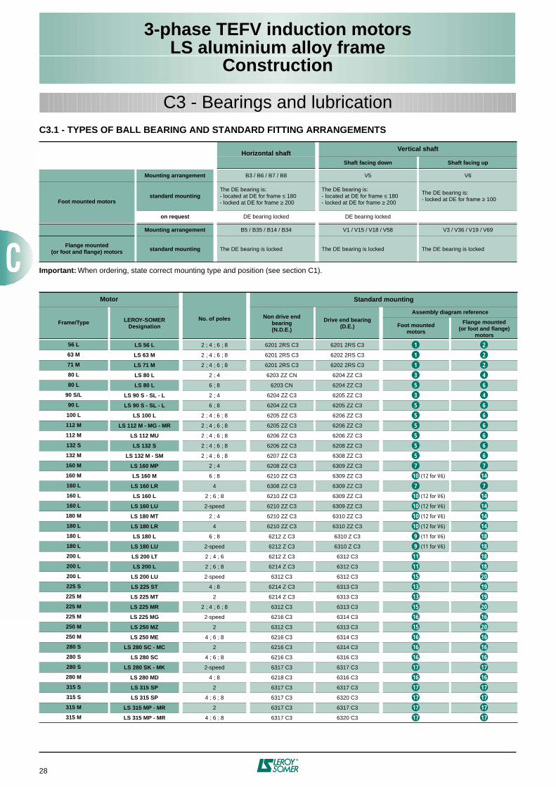
C3.1 - TYPES OF BALL BEARING AND STANDARD FITTING ARRANGEMENTS
Important:
When ordering, state correct mounting type and position (see section C1).
Horizontal shaftVertical shaft
Shaft facing down Shaft facing up
Mounting arrangement
B3 / B6 / B7 / B8 V5 V6
Foot mounted motorsstandard mounting
The DE bearing is:- located at DE for frame
≤
180- locked at DE for frame
≥
200
The DE bearing is:- located at DE for frame
≤
180- locked at DE for frame
≥
200
The DE bearing is:- locked at DE for frame
≥
100
on request
DE bearing locked DE bearing locked
Mounting arrangement
B5 / B35 / B14 / B34 V1 / V15 / V18 / V58 V3 / V36 / V19 / V69
Flange mounted(or foot and flange) motors standard mounting
The DE bearing is locked The DE bearing is locked The DE bearing is locked
Motor
No. of poles
Standard mounting
Frame/Type LEROY-SOMERDesignation
Non drive end bearing(N.D.E.)
Drive end bearing(D.E.)
Assembly diagram reference
Foot mountedmotors
Flange mounted (or foot and flange)
motors
56 L LS 56 L
2 ; 4 ; 6 ; 8 6201 2RS C3 6201 2RS C3
63 M LS 63 M
2 ; 4 ; 6 ; 8 6201 2RS C3 6202 2RS C3
71 M LS 71 M
2 ; 4 ; 6 ; 8 6201 2RS C3 6202 2RS C3
80 L LS 80 L
2 ; 4 6203 ZZ CN 6204 ZZ C3
80 L LS 80 L
6 ; 8 6203 CN 6204 ZZ C3
90 S/L LS 90 S - SL - L
2 ; 4 6204 ZZ C3 6205 ZZ C3
90 L LS 90 S - SL - L
6 ; 8 6204 ZZ C3 6205 ZZ C3
100 L LS 100 L
2 ; 4 ; 6 ; 8 6205 ZZ C3 6206 ZZ C3
112 M LS 112 M - MG - MR
2 ; 4 ; 6 ; 8 6205 ZZ C3 6206 ZZ C3
112 M LS 112 MU
2 ; 4 ; 6 ; 8 6206 ZZ C3 6206 ZZ C3
132 S LS 132 S
2 ; 4 ; 6 ; 8 6206 ZZ C3 6208 ZZ C3
132 M LS 132 M - SM
2 ; 4 ; 6 ; 8 6207 ZZ C3 6308 ZZ C3
160 M LS 160 MP
2 ; 4 6208 ZZ C3 6309 ZZ C3
160 M LS 160 M
6 ; 8 6210 ZZ C3 6309 ZZ C3
(12 for V6)
160 L LS 160 LR
4 6308 ZZ C3 6309 ZZ C3
160 L LS 160 L
2 ; 6 ; 8 6210 ZZ C3 6309 ZZ C3
(12 for V6)
160 L LS 160 LU
2-speed 6210 ZZ C3 6309 ZZ C3
(12 for V6)
180 M LS 180 MT
2 ; 4 6210 ZZ C3 6310 ZZ C3
(12 for V6)
180 L LS 180 LR
4 6210 ZZ C3 6310 ZZ C3
(12 for V6)
180 L LS 180 L
6 ; 8 6212 Z C3 6310 Z C3
(11 for V6)
180 L LS 180 LU
2-speed 6212 Z C3 6310 Z C3
(11 for V6)
200 L LS 200 LT
2 ; 4 ; 6 6212 Z C3 6312 C3
200 L LS 200 L
2 ; 6 ; 8 6214 Z C3 6312 C3
200 L LS 200 LU
2-speed 6312 C3 6312 C3
225 S LS 225 ST
4 ; 8 6214 Z C3 6313 C3
225 M LS 225 MT
2 6214 Z C3 6313 C3
225 M LS 225 MR
2 ; 4 ; 6 ; 8 6312 C3 6313 C3
225 M LS 225 MG
2-speed 6216 C3 6314 C3
250 M LS 250 MZ
2 6312 C3 6313 C3
250 M LS 250 ME
4 ; 6 ; 8 6216 C3 6314 C3
280 S LS 280 SC - MC
2 6216 C3 6314 C3
280 S LS 280 SC
4 ; 6 ; 8 6216 C3 6316 C3
280 S LS 280 SK - MK
2-speed 6317 C3 6317 C3
280 M LS 280 MD
4 ; 8 6218 C3 6316 C3
315 S LS 315 SP
2 6317 C3 6317 C3
315 S LS 315 SP
4 ; 6 ; 8 6317 C3 6320 C3
315 M LS 315 MP - MR
2 6317 C3 6317 C3
315 M LS 315 MP - MR
4 ; 6 ; 8 6317 C3 6320 C3
C3 - Bearings and lubrication
1 2
1 2
1 2
3 4
5 6
3 4
5 6
5 6
5 6
5 6
5 6
5 6
7 7
10 14
7 7
10 14
10 14
10 14
10 14
9 18
9 18
11 18
11 18
15 20
13 19
13 19
15 20
16 16
15 20
16 16
16 16
16 16
17 17
16 16
17 17
17 17
17 17
17 17
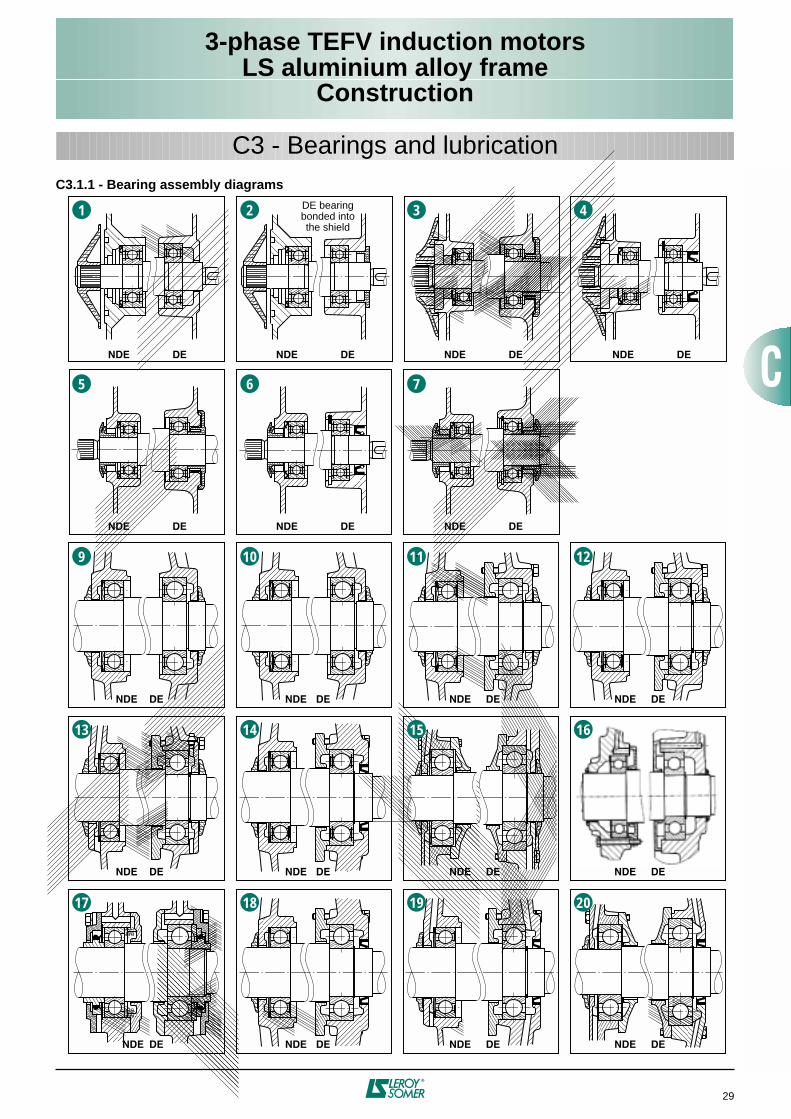
3-phase TEFV induction motorsLS aluminium alloy frame
Construction
29
C3 - Bearings and lubrication
C3.1.1 - Bearing assembly diagrams
1 2 3 4
5 6 7
9 10 11 12
13 14 15 16
17 18 19 20
NDE DE NDE DE NDE DE
NDE DE NDE DE NDE DE
NDE DE NDE DE NDE DE NDE DE
NDE DE NDE DE NDE DE NDE DE
NDE DE NDE DE NDE DE NDE DE
NDE DE
DE bearingbonded intothe shield
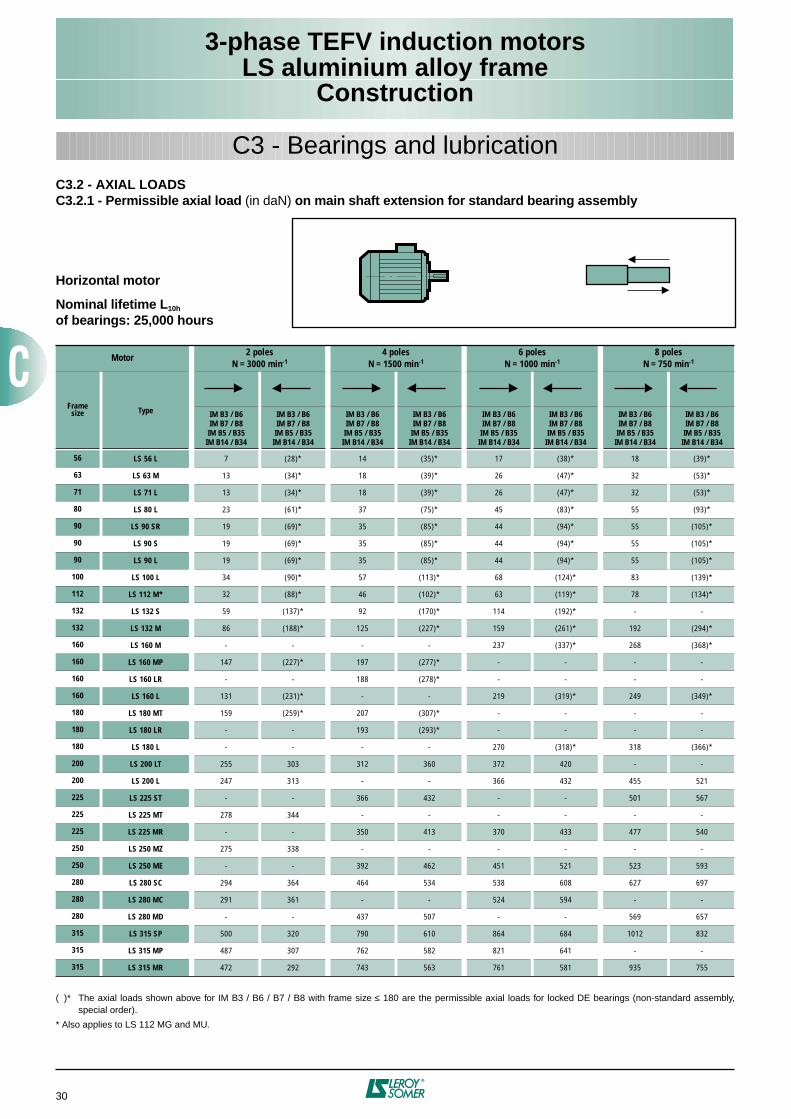
3-phase TEFV induction motorsLS aluminium alloy frame
Construction
30
C3 - Bearings and lubrication
C3.2 - AXIAL LOADSC3.2.1 - Permissible axial load
(in daN)
on main shaft extension for standard bearing assembly
Horizontal motor
Nominal lifetime L
10h
of bearings: 25,000 hours
( )* The axial loads shown above for IM B3 / B6 / B7 / B8 with frame size
≤
180 are the permissible axial loads for locked DE bearings (non-standard assembly,special order).
* Also applies to LS 112 MG and MU.
Motor 2 polesN = 3000 min
-1
4 polesN = 1500 min
-1
6 polesN = 1000 min
-1
8 polesN = 750 min
-1
Framesize Type IM B3 / B6
IM B7 / B8IM B5 / B35IM B14 / B34
IM B3 / B6IM B7 / B8IM B5 / B35IM B14 / B34
IM B3 / B6IM B7 / B8IM B5 / B35IM B14 / B34
IM B3 / B6IM B7 / B8IM B5 / B35IM B14 / B34
IM B3 / B6IM B7 / B8IM B5 / B35IM B14 / B34
IM B3 / B6IM B7 / B8IM B5 / B35IM B14 / B34
IM B3 / B6IM B7 / B8IM B5 / B35IM B14 / B34
IM B3 / B6IM B7 / B8IM B5 / B35IM B14 / B34
56 LS 56 L
7 (28)* 14 (35)* 17 (38)* 18 (39)*
63 LS 63 M
13 (34)* 18 (39)* 26 (47)* 32 (53)*
71 LS 71 L
13 (34)* 18 (39)* 26 (47)* 32 (53)*
80 LS 80 L
23 (61)* 37 (75)* 45 (83)* 55 (93)*
90 LS 90 SR
19 (69)* 35 (85)* 44 (94)* 55 (105)*
90 LS 90 S
19 (69)* 35 (85)* 44 (94)* 55 (105)*
90 LS 90 L
19 (69)* 35 (85)* 44 (94)* 55 (105)*
100 LS 100 L
34 (90)* 57 (113)* 68 (124)* 83 (139)*
112 LS 112 M*
32 (88)* 46 (102)* 63 (119)* 78 (134)*
132 LS 132 S
59 (137)* 92 (170)* 114 (192)* - -
132 LS 132 M
86 (188)* 125 (227)* 159 (261)* 192 (294)*
160 LS 160 M
- - - - 237 (337)* 268 (368)*
160 LS 160 MP
147 (227)* 197 (277)* - - - -
160 LS 160 LR
- - 188 (278)* - - - -
160 LS 160 L
131 (231)* - - 219 (319)* 249 (349)*
180 LS 180 MT
159 (259)* 207 (307)* - - - -
180 LS 180 LR - - 193 (293)* - - - -
180 LS 180 L - - - - 270 (318)* 318 (366)*
200 LS 200 LT 255 303 312 360 372 420 - -
200 LS 200 L 247 313 - - 366 432 455 521
225 LS 225 ST - - 366 432 - - 501 567
225 LS 225 MT 278 344 - - - - - -
225 LS 225 MR - - 350 413 370 433 477 540
250 LS 250 MZ 275 338 - - - - - -
250 LS 250 ME - - 392 462 451 521 523 593
280 LS 280 SC 294 364 464 534 538 608 627 697
280 LS 280 MC 291 361 - - 524 594 - -
280 LS 280 MD - - 437 507 - - 569 657
315 LS 315 SP 500 320 790 610 864 684 1012 832
315 LS 315 MP 487 307 762 582 821 641 - -
315 LS 315 MR 472 292 743 563 761 581 935 755
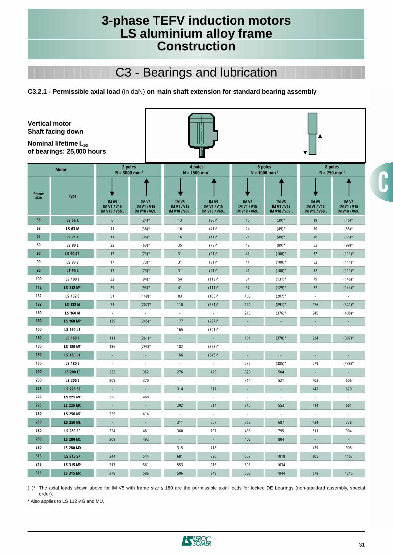
3-phase TEFV induction motorsLS aluminium alloy frame
Construction
31
C3 - Bearings and lubricationC3.2.1 - Permissible axial load (in daN) on main shaft extension for standard bearing assembly
Vertical motorShaft facing down
Nominal lifetime L10h
of bearings: 25,000 hours
( )* The axial loads shown above for IM V5 with frame size ≤ 180 are the permissible axial loads for locked DE bearings (non-standard assembly, specialorder).
* Also applies to LS 112 MG and MU.
Motor 2 polesN = 3000 min-1
4 polesN = 1500 min-1
6 polesN = 1000 min-1
8 polesN = 750 min-1
Framesize Type
IM V5IM V1 / V15
IM V18 / V58..
IM V5IM V1 / V15
IM V18 / V69..
IM V5IM V1 / V15
IM V18 / V69..
IM V5IM V1 / V15
IM V18 / V69..
IM V5IM V1 / V15
IM V18 / V69..
IM V5IM V1 / V15
IM V18 / V69..
IM V5IM V1 / V15
IM V18 / V69..
IM V5IM V1 / V15
IM V18 / V69..
56 LS 56 L 6 (24)* 13 (36)* 16 (39)* 19 (40)*
63 LS 63 M 11 (36)* 16 (41)* 24 (49)* 30 (55)*
71 LS 71 L 11 (36)* 16 (41)* 24 (49)* 30 (55)*
80 LS 80 L 22 (63)* 35 (79)* 42 (89)* 52 (99)*
90 LS 90 SR 17 (73)* 31 (91)* 41 (100)* 52 (111)*
90 LS 90 S 17 (73)* 31 (91)* 41 (100)* 52 (111)*
90 LS 90 L 17 (73)* 31 (91)* 41 (100)* 52 (111)*
100 LS 100 L 32 (94)* 54 (119)* 64 (131)* 79 (146)*
112 LS 112 M* 29 (93)* 41 (111)* 57 (129)* 72 (144)*
132 LS 132 S 51 (149)* 83 (185)* 105 (207)* - -
132 LS 132 M 73 (207)* 110 (251)* 140 (291)* 176 (321)*
160 LS 160 M - - - - 213 (376)* 245 (408)*
160 LS 160 MP 129 (245)* 177 (297)* - - - -
160 LS 160 LR - - 165 (301)* - - - -
160 LS 160 L 111 (261)* - - 191 (370)* 224 (397)*
180 LS 180 MT 136 (293)* 182 (353)* - - - -
180 LS 180 LR - - 166 (345)* - - - -
180 LS 180 L - - - - 232 (385)* 279 (438)*
200 LS 200 LT 222 352 276 429 329 504 - -
200 LS 200 L 209 370 - - 314 521 403 606
225 LS 225 ST - - 314 517 - - 443 670
225 LS 225 MT 236 408 - - - - - -
225 LS 225 MR - - 292 514 310 553 414 661
250 LS 250 MZ 225 414 - - - - - -
250 LS 250 ME - - 311 607 363 687 424 778
280 LS 280 SC 224 481 360 707 436 795 511 904
280 LS 280 MC 209 492 - - 406 804 - -
280 LS 280 MD - - 315 718 - - 439 908
315 LS 315 SP 344 544 601 896 657 1018 805 1167
315 LS 315 MP 317 561 553 916 591 1034 - -
315 LS 315 MR 278 586 506 949 508 1044 678 1215
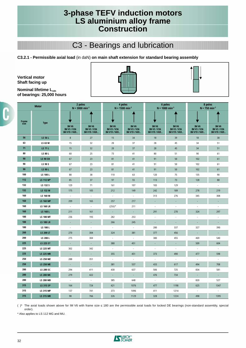
3-phase TEFV induction motorsLS aluminium alloy frame
Construction
32
C3 - Bearings and lubricationC3.2.1 - Permissible axial load (in daN) on main shaft extension for standard bearing assembly
Vertical motorShaft facing up
Nominal lifetime L10h
of bearings: 25,000 hours
( )* The axial loads shown above for IM V6 with frame size ≤ 180 are the permissible axial loads for locked DE bearings (non-standard assembly, specialorder).
* Also applies to LS 112 MG and MU.
Motor 2 polesN = 3000 min-1
4 polesN = 1500 min-1
6 polesN = 1000 min-1
8 polesN = 750 min-1
Framesize Type
IM V6IM V3 / V36
IM V19 / V69..
IM V6IM V3 / V36
IM V19 / V69..
IM V6IM V3 / V36
IM V19 / V69..
IM V6IM V3 / V36
IM V19 / V69..
IM V6IM V3 / V36
IM V19 / V69..
IM V6IM V3 / V36
IM V19 / V69..
IM V6IM V3 / V36
IM V19 / V69..
IM V6IM V3 / V36
IM V19 / V69..
56 LS 56 L 8 27 15 34 18 39 18 38
63 LS 63 M 15 32 20 37 28 45 34 51
71 LS 71 L 15 32 20 37 28 45 34 51
80 LS 80 L 60 25 73 41 80 51 90 61
90 LS 90 SR 67 23 81 41 91 50 102 61
90 LS 90 S 67 23 81 41 91 50 102 61
90 LS 90 L 67 23 81 41 91 50 102 61
100 LS 100 L 88 38 110 63 120 75 135 90
112 LS 112 M* 85 37 97 55 113 73 128 88
132 LS 132 S 129 71 161 107 183 129 - -
132 LS 132 M 175 105 212 149 242 189 278 219
160 LS 160 M - - - - 313 276 345 308
160 LS 160 MP 209 165 257 217 - - - -
160 LS 160 LR - - (255)* 211 - - - -
160 LS 160 L 211 161 - - 291 270 324 297
180 LS 180 MT 236 193 282 253 - - - -
180 LS 180 LR - - 266 245 - - - -
180 LS 180 L - - - - 280 337 327 390
200 LS 200 LT 270 304 324 381 377 456 - -
200 LS 200 L 275 304 - - 380 455 469 540
225 LS 225 ST - - 380 451 - - 509 604
225 LS 225 MT 302 342 - - - - - -
225 LS 225 MR - - 355 451 373 490 477 598
250 LS 250 MZ 288 351 - - - - - -
250 LS 250 ME - - 381 537 433 617 494 708
280 LS 280 SC 294 411 430 637 506 725 834 581
280 LS 280 MC 279 422 - - 476 734 - -
280 LS 280 MD - - 385 648 - - 820 527
315 LS 315 SP 164 724 421 1076 477 1198 625 1347
315 LS 315 MP 137 741 373 1096 411 1214 - -
315 LS 315 MR 98 766 326 1129 328 1224 498 1395
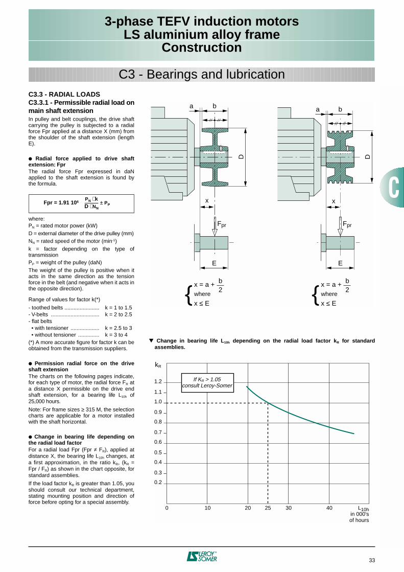
3-phase TEFV induction motorsLS aluminium alloy frame
Construction
33
C3 - Bearings and lubricationC3.3 - RADIAL LOADSC3.3.1 - Permissible radial load onmain shaft extensionIn pulley and belt couplings, the drive shaftcarrying the pulley is subjected to a radialforce Fpr applied at a distance X (mm) fromthe shoulder of the shaft extension (lengthE).
Radial force applied to drive shaftextension: FprThe radial force Fpr expressed in daNapplied to the shaft extension is found bythe formula.
where:PN = rated motor power (kW)D = external diameter of the drive pulley (mm)NN = rated speed of the motor (min-1)k = factor depending on the type oftransmissionPP = weight of the pulley (daN)The weight of the pulley is positive when itacts in the same direction as the tensionforce in the belt (and negative when it acts inthe opposite direction).
Range of values for factor k(*)
- toothed belts ....................... k = 1 to 1.5- V-belts ................................ k = 2 to 2.5- flat belts • with tensioner ................... k = 2.5 to 3 • without tensioner .............. k = 3 to 4(*) A more accurate figure for factor k can beobtained from the transmission suppliers.
Permission radial force on the driveshaft extensionThe charts on the following pages indicate,for each type of motor, the radial force FR ata distance X permissible on the drive endshaft extension, for a bearing life L10h of25,000 hours.
Note: For frame sizes ≥ 315 M, the selectioncharts are applicable for a motor installedwith the shaft horizontal.
Change in bearing life depending onthe radial load factorFor a radial load Fpr (Fpr ≠ FR), applied atdistance X, the bearing life L10h changes, ata first approximation, in the ratio kR, (kR =Fpr / FR) as shown in the chart opposite, forstandard assemblies.
If the load factor kR is greater than 1.05, youshould consult our technical department,stating mounting position and direction offorce before opting for a special assembly.
Fpr = 1.91 106PN k⋅D NN⋅--------------- PP±
Change in bearing life L10h depending on the radial load factor kR for standardassemblies.
E
Fpr
D
x
a b
E
Fpr
a b
D
x
x = a +
x ≤ Ewhere
b2
x = a +
x ≤ Ewhere
b2
0 10 20 30 40 L10hin 000'sof hours
0.2
0.4
0.6
0.8
1.0
1.2
kR
0.3
0.5
0.7
0.9
1.1
25
If KR > 1.05consult Leroy-Somer
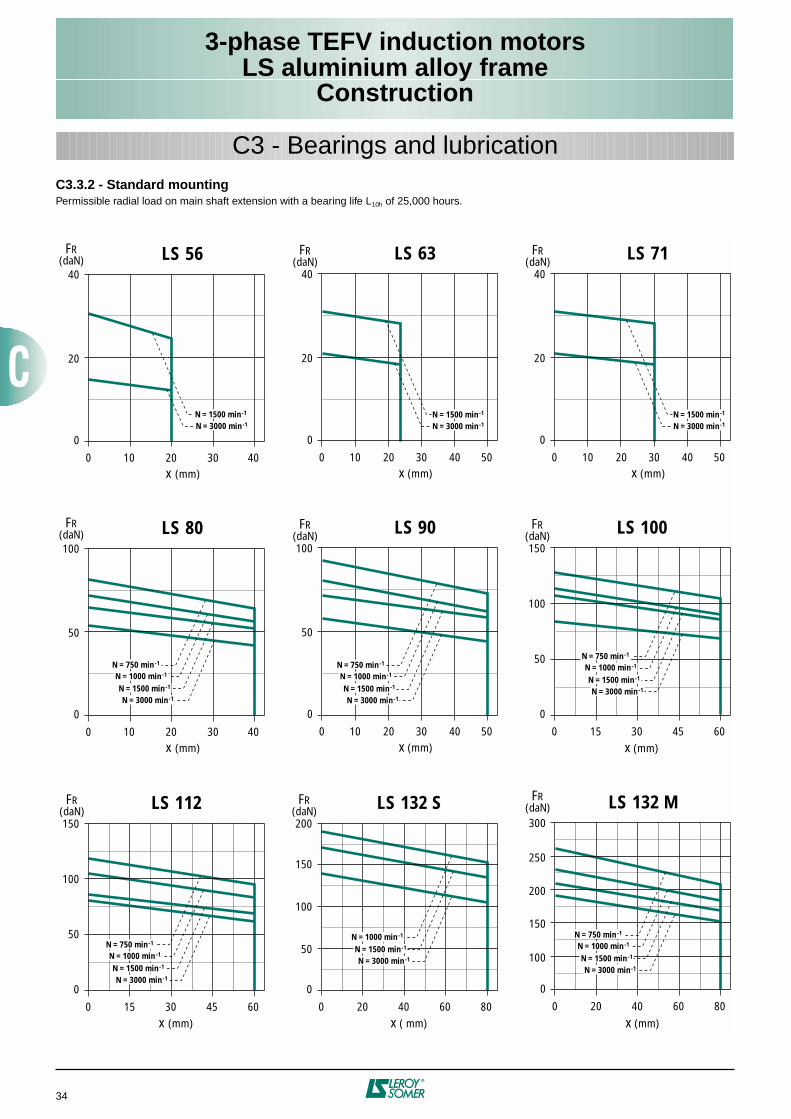
3-phase TEFV induction motorsLS aluminium alloy frame
Construction
34
C3 - Bearings and lubricationC3.3.2 - Standard mountingPermissible radial load on main shaft extension with a bearing life L10h of 25,000 hours.
0 10 20 40
0
40
LS 56FR(daN)
x (mm)
20
30 0 10 20 40 50
0
40
LS 63FR(daN)
x (mm)
20
30
0 15 30 45 600
150
LS 112FR(daN)
x (mm)
100
50N = 750 min -1
N = 1000 min -1
N = 1500 min -1
N = 3000 min -1
0 20 40 60 800
200
LS 132 SFR(daN)
x ( mm)
100
150
50N = 1000 min -1
N = 1500 min -1
N = 3000 min -1
0 20 40 60 800
300
LS 132 MFR(daN)
x (mm)
200
250
150
100
N = 750 min -1
N = 1000 min -1
N = 1500 min -1
N = 3000 min -1
0 10 20 40
0
100
LS 80FR(daN)
x (mm)
50
30
N = 750 min -1
N = 1000 min -1
N = 1500 min -1
N = 3000 min -1
0 10 20 40 50
0
100
LS 90FR(daN)
x (mm)
50
30
N = 750 min -1
N = 1000 min -1
N = 1500 min -1
N = 3000 min -1
0 15 30 45 600
150
LS 100FR(daN)
x (mm)
100
50 N = 750 min -1
N = 1000 min -1
N = 1500 min -1
N = 3000 min -1
0 10 20 40 50
0
40
LS 71FR(daN)
x (mm)
20
30
N = 1500 min -1
N = 3000 min -1N = 1500 min -1
N = 3000 min -1
N = 1500 min -1
N = 3000 min -1
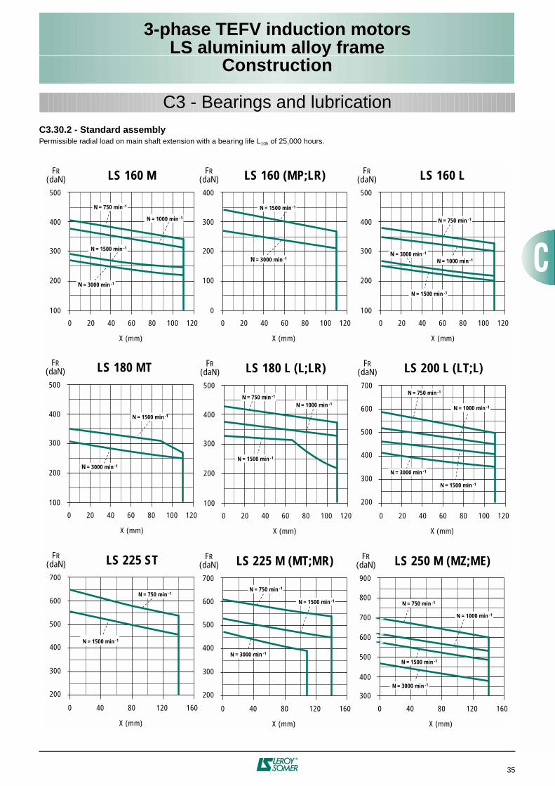
3-phase TEFV induction motorsLS aluminium alloy frame
Construction
35
C3 - Bearings and lubricationC3.30.2 - Standard assemblyPermissible radial load on main shaft extension with a bearing life L10h of 25,000 hours.
0 20 40 60 80 100 120
100
200
300
400
500
FR (daN)
N = 3000 min -1
N = 1000 min -1
N = 1500 min -1
N = 750 min -1
X (mm)
LS 160 M
0 20 40 60 80 100 120
0
100
200
300
400
FR (daN)
N = 3000 min -1
N = 1500 min -1
X (mm)
LS 160 (MP;LR)
0 20 40 60 80 100 120
100
200
300
400
500
FR (daN)
N = 1000 min -1
N = 1500 min -1
N = 750 min -1
X (mm)
LS 180 L (L;LR)
0 20 40 60 80 100 120
300
200
400
500
600
700
FR (daN)
N = 1000 min -1
N = 1500 min -1
N = 3000 min -1
N = 750 min -1
X (mm)
LS 200 L (LT;L)
0 40 80 120 160
300
200
400
500
600
700
FR (daN)
X (mm)
LS 225 ST
0 20 40 60 80 100 120
100
200
300
400
500
FR (daN)
N = 3000 min -1
N = 1000 min -1
N = 1500 min -1
N = 750 min -1
X (mm)
LS 160 L
0 20 40 60 80 100 120
100
200
300
400
500
FR (daN)
N = 3000 min -1
N = 1500 min -1
X (mm)
LS 180 MT
0 40 80 120 160
300
200
400
500
600
700
FR (daN)
X (mm)
LS 225 M (MT;MR)
N = 1500 min -1
N = 750 min -1
N = 1500 min -1
N = 3000 min -1
N = 750 min -1
0 40 80 120 160
500
400
300
600
700
800
900
FR (daN)
X (mm)
LS 250 M (MZ;ME)
N = 1500 min -1
N = 3000 min -1
N = 750 min -1
N = 1000 min -1
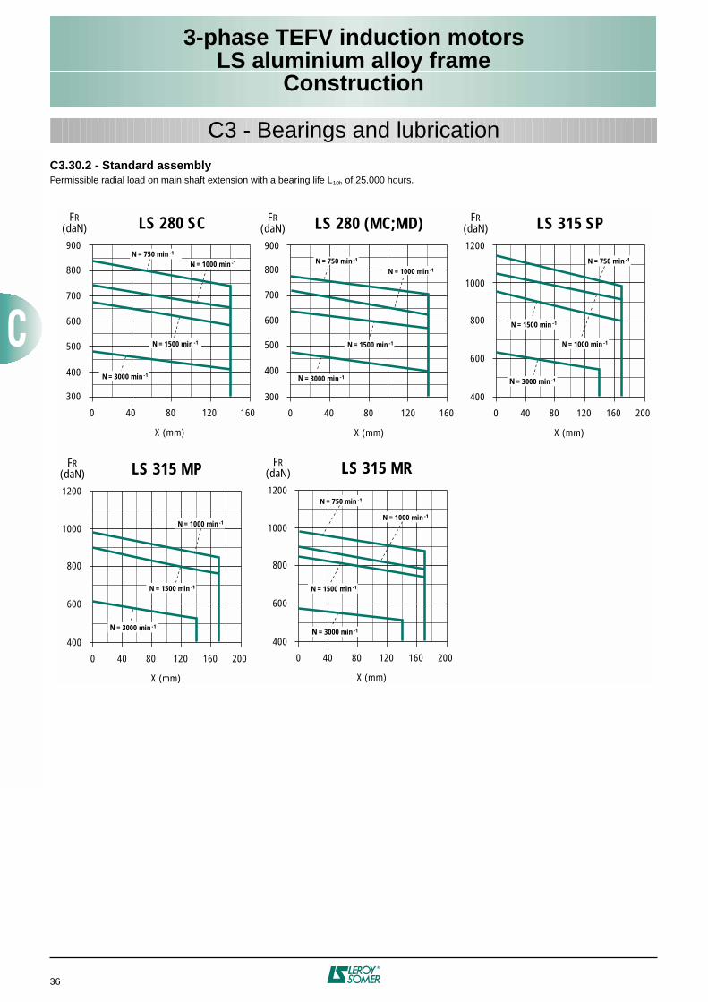
3-phase TEFV induction motorsLS aluminium alloy frame
Construction
36
C3 - Bearings and lubricationC3.30.2 - Standard assemblyPermissible radial load on main shaft extension with a bearing life L10h of 25,000 hours.
0 40 80 120 160
300
400
500
600
700
800
900
FR (daN)
N = 3000 min -1
N = 1500 min -1
N = 1000 min -1
N = 750 min -1
X (mm)
LS 280 (MC;MD)
0 40 80 120 160 200
400
600
800
1000
1200
FR (daN)
N = 3000 min -1
N = 1000 min -1
N = 1500 min -1
N = 750 min -1
X (mm)
LS 315 SP
0 40 80 120 160 200
400
600
800
1000
1200
FR (daN)
N = 3000 min -1
N = 1000 min -1
N = 1500 min -1
N = 750 min -1
X (mm)
LS 315 MR
0 40 80 120 160 200
400
600
800
1000
1200
FR (daN)
N = 3000 min -1
N = 1000 min -1
N = 1500 min -1
X (mm)
LS 315 MP
0 40 80 120 160
500
400
300
600
700
800
900
FR (daN)
X (mm)
LS 280 SC
N = 1500 min -1
N = 3000 min -1
N = 750 min -1
N = 1000 min -1
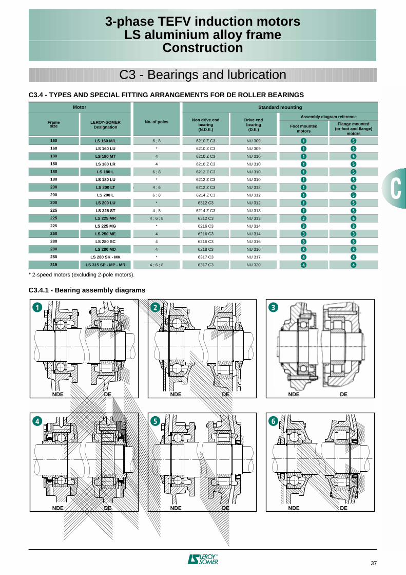
3-phase TEFV induction motorsLS aluminium alloy frame
Construction
37
C3 - Bearings and lubricationC3.4 - TYPES AND SPECIAL FITTING ARRANGEMENTS FOR DE ROLLER BEARINGS
* 2-speed motors (excluding 2-pole motors).
C3.4.1 - Bearing assembly diagrams
Motor
No. of poles
Standard mounting
Frame size
LEROY-SOMERDesignation
Non drive end bearing(N.D.E.)
Drive endbearing(D.E.)
Assembly diagram reference
Foot mountedmotors
Flange mounted (or foot and flange)
motors
160 LS 160 M/L 6 ; 8 6210 Z C3 NU 309
160 LS 160 LU * 6210 Z C3 NU 309
180 LS 180 MT 4 6210 Z C3 NU 310
180 LS 180 LR 4 6210 Z C3 NU 310
180 LS 180 L 6 ; 8 6212 Z C3 NU 310
180 LS 180 LU * 6212 Z C3 NU 310
200 LS 200 LT @ 4 ; 6 6212 Z C3 NU 312
200 LS 200 L 6 ; 8 6214 Z C3 NU 312
200 LS 200 LU * 6312 C3 NU 312
225 LS 225 ST 4 ; 8 6214 Z C3 NU 313
225 LS 225 MR 4 ; 6 ; 8 6312 C3 NU 313
225 LS 225 MG * 6216 C3 NU 314
250 LS 250 ME 4 6216 C3 NU 314
280 LS 280 SC 4 6216 C3 NU 316
280 LS 280 MD 4 6218 C3 NU 316
280 LS 280 SK - MK * 6317 C3 NU 317
315 LS 315 SP - MP - MR 4 ; 6 ; 8 6317 C3 NU 320
1
NDE DE
2
NDE DE
3
NDE DE
4
NDE DE
5
NDE DE
6
NDE DE
1 5
1 5
1
1 5
1 5
1 5
1 5
1 5
1 5
1 5
2 6
3 3
3 3
3 3
3
4 4
4 4
5
3
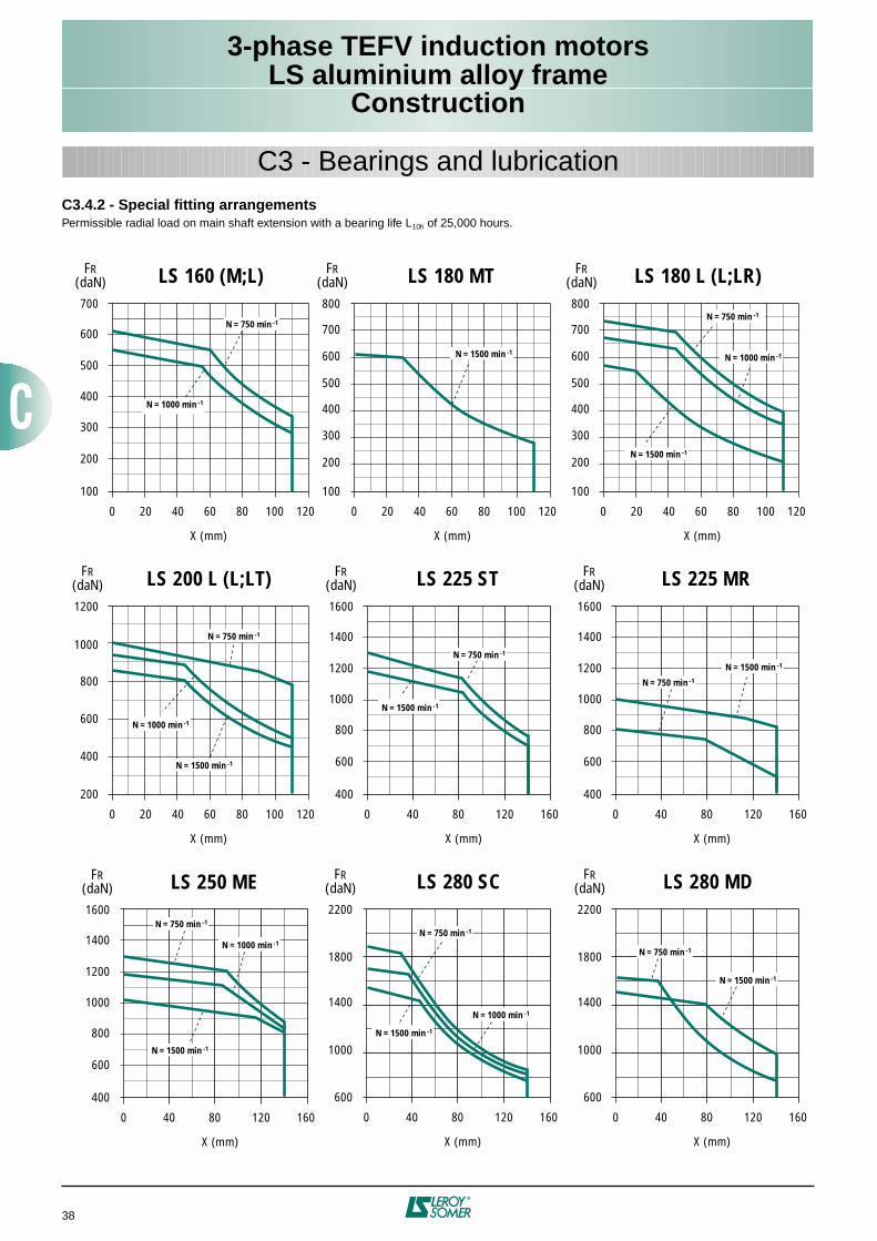
3-phase TEFV induction motorsLS aluminium alloy frame
Construction
38
C3 - Bearings and lubricationC3.4.2 - Special fitting arrangementsPermissible radial load on main shaft extension with a bearing life L10h of 25,000 hours.
0 20 40 60 80 100 120
100
200
300
400
500
600
700
100
200
300
400
500
600
700
800
FR (daN)
N = 1000 min -1
N = 750 min -1
X (mm)
LS 160 (M;L)
0 40 80 120 160
400
600
800
1000
1200
1400
1600
FR (daN)
N = 1500 min -1
N = 750 min -1
X (mm)
LS 225 ST
0 40 80 120 160
400
600
800
1000
1200
1400
1600
FR (daN)
N = 1500 min -1
N = 750 min -1
X (mm)
LS 225 MR
0 40 80 120 160
400
600
800
1000
1200
1400
1600
FR (daN)
N = 1000 min -1
N = 750 min -1
X (mm)
LS 250 ME
0 40 80 120 160
600
1000
1400
1800
2200
FR (daN)
N = 750 min -1
X (mm)
LS 280 SC
0 20 40 60 80 100 120
200
600
400
800
1000
1200
FR (daN)
N = 1000 min -1
N = 1500 min -1
N = 1500 min -1
N = 750 min -1
X (mm)
LS 200 L (L;LT)
0 20 40 60 80 100 120
FR (daN)
N = 1500 min -1
X (mm)
LS 180 MT
100
200
300
400
500
600
700
800
N = 1500 min -1
N = 1000 min -1
N = 750 min -1
0 20 40 60 80 100 120
FR (daN)
X (mm)
LS 180 L (L;LR)
N = 1500 min -1
N = 1000 min -1
0 40 80 120 160
600
1000
1400
1800
2200
FR (daN)
N = 750 min -1
X (mm)
LS 280 MD
N = 1500 min -1
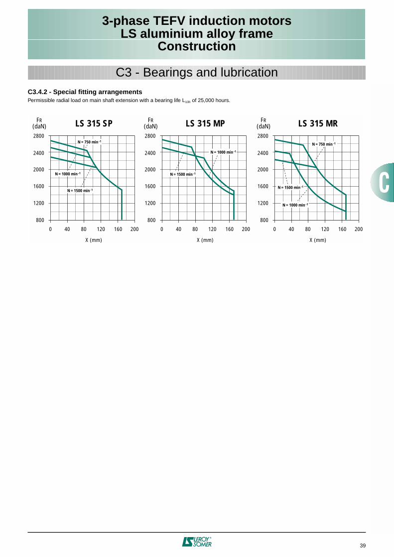
3-phase TEFV induction motorsLS aluminium alloy frame
Construction
39
C3 - Bearings and lubricationC3.4.2 - Special fitting arrangementsPermissible radial load on main shaft extension with a bearing life L10h of 25,000 hours.
0 40 80 120 160 200
800
1600
1200
2000
2400
2800
FR (daN)
N = 1500 min -1
N = 1000 min -1
N = 750 min -1
X (mm)
LS 315 SP
0 40 80 120 160 200
800
1600
1200
2000
2400
2800
FR (daN)
N = 1000 min -1
N = 1500 min -1
X (mm)
LS 315 MP
0 40 80 120 160 200
800
1600
1200
2000
2400
2800
FR (daN)
N = 1000 min -1
N = 1500 min -1
N = 750 min -1
X (mm)
LS 315 MR
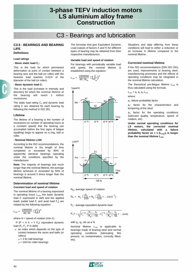
3-phase TEFV induction motorsLS aluminium alloy frame
Construction
40
C3 - Bearings and lubricationC3.5 - BEARINGS AND BEARINGLIFEDefinitions
Load ratings
- Basic static load Co:
This is the load for which permanentdeformation at point of contact between abearing race and the ball (or roller) with theheaviest load reaches 0.01% of thediameter of the ball (or roller).
- Basic dynamic load C:
This is the load (constant in intensity anddirection) for which the nominal lifetime ofthe bearing will reach 1 millionrevolutions.
The static load rating Co and dynamic loadrating C are obtained for each bearing byfollowing the method in ISO 281.
LifetimeThe lifetime of a bearing is the number ofrevolutions (or number of operating hours ata constant speed) that the bearing canaccomplish before the first signs of fatigue(spalling) begin to appear on a ring, ball orroller.
- Nominal lifetime L10h
According to the ISO recommendations, thenominal lifetime is the length of timecompleted or exceeded by 90% ofapparently identical bearings operatingunder the conditions specified by themanufacturer.
Note: The majority of bearings last muchlonger than the nominal lifetime; the averagelifetime achieved or exceeded by 50% ofbearings is around 5 times longer than thenominal lifetime.
Determination of nominal lifetimeConstant load and speed of rotation
The nominal lifetime of a bearing expressedin operating hours L10h, the basic dynamicload C expressed in daN and the appliedloads (radial load Fr and axial load Fa) arerelated by the following equation:
L10h =
where N = speed of rotation (min-1)
P (P = X Fr + Y Fa): equivalent dynamicload (Fr, Fa, P in daN) p: an index which depends on the type of
contact between the races and balls (orrollers)
p = 3 for ball bearings p = 10/3 for roller bearings
The formulae that give Equivalent DynamicLoad (values of factors X and Y) for differenttypes of bearing may be obtained from theirrespective manufacturers.
Variable load and speed of rotation
For bearings with periodically variable loadand speed, the nominal lifetime isestablished using the equation:
L10h =
Nm: average speed of rotation
Nm =
Pm : average equivalent dynamic load
Pm=
with q1, q2, etc as a %
Nominal lifetime L10h is applicable tobearings made of bearing steel and normaloperating conditions (lubricating filmpresent, no contamination, correctly fitted,etc).
Situations and data differing from theseconditions will lead to either a reduction oran increase in lifetime compared to thenominal lifetime.
Corrected nominal lifetimeIf the ISO recommendations (DIN ISO 281)are used, improvements to bearing steel,manufacturing processes and the effects ofoperating conditions may be integrated inthe nominal lifetime calculation.
The theoretical pre-fatigue lifetime Lnah isthus calculated using the formula:
Lnah = a1 a2 a3 L10h
where:
a1: failure probability factor
a2: factor for the characteristics andtempering of the steel
a3: factor for the operating conditions(lubricant quality, temperature, speed ofrotation, etc)
Under normal operating conditions forLS motors, the corrected nominallifetime, calculated with a failureprobability factor a1 = 1 (L10ah), is longerthan the nominal lifetime L10h.
Speed N
Nm
N1 N4
N2
N3
Load P
PmP1
P4
P2
P3
100 %
q1 % q2 % q3 % q4 %
q1 % q2 % q3 % q4 %
Time
Time
100000060 Nm⋅-----------------------
CPm--------( )p⋅
100000060 N⋅-----------------------
CP----( )p⋅
N1
q1
100---------- N2
q2
100---------- … min
1–( )+⋅+⋅
P11 p⁄ N1
Nm------
q1
100----- P21 p⁄ N2
Nm------
q2
100----- …+⋅ ⋅+⋅ ⋅1 p⁄ daN( )
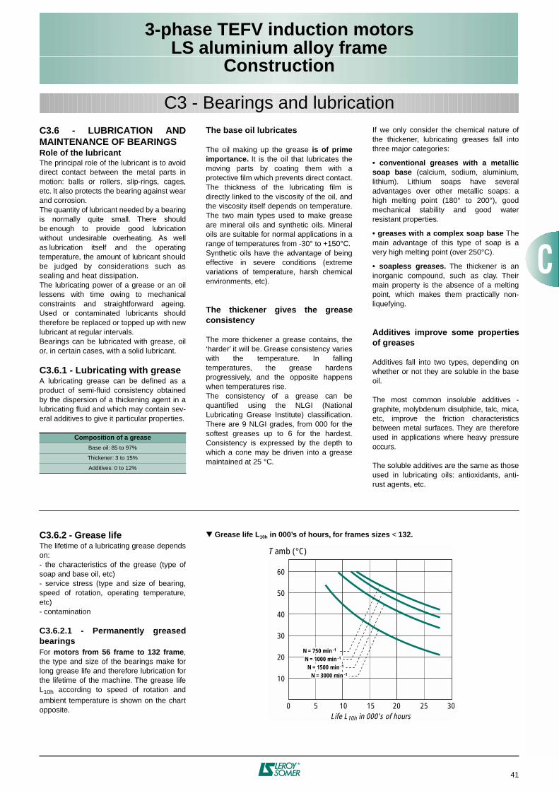
3-phase TEFV induction motorsLS aluminium alloy frame
Construction
41
C3 - Bearings and lubricationC3.6 - LUBRICATION ANDMAINTENANCE OF BEARINGSRole of the lubricantThe principal role of the lubricant is to avoiddirect contact between the metal parts inmotion: balls or rollers, slip-rings, cages,etc. It also protects the bearing against wearand corrosion.The quantity of lubricant needed by a bearingis normally quite small. There shouldbe enough to provide good lubricationwithout undesirable overheating. As wellas lubrication itself and the operatingtemperature, the amount of lubricant shouldbe judged by considerations such assealing and heat dissipation.The lubricating power of a grease or an oillessens with time owing to mechanicalconstraints and straightforward ageing.Used or contaminated lubricants shouldtherefore be replaced or topped up with newlubricant at regular intervals.Bearings can be lubricated with grease, oilor, in certain cases, with a solid lubricant.
C3.6.1 - Lubricating with greaseA lubricating grease can be defined as aproduct of semi-fluid consistency obtainedby the dispersion of a thickening agent in alubricating fluid and which may contain sev-eral additives to give it particular properties.
The base oil lubricates
The oil making up the grease is of primeimportance. It is the oil that lubricates themoving parts by coating them with aprotective film which prevents direct contact.The thickness of the lubricating film isdirectly linked to the viscosity of the oil, andthe viscosity itself depends on temperature.The two main types used to make greaseare mineral oils and synthetic oils. Mineraloils are suitable for normal applications in arange of temperatures from -30° to +150°C.Synthetic oils have the advantage of beingeffective in severe conditions (extremevariations of temperature, harsh chemicalenvironments, etc).
The thickener gives the greaseconsistency
The more thickener a grease contains, the‘harder’ it will be. Grease consistency varieswith the temperature. In fallingtemperatures, the grease hardensprogressively, and the opposite happenswhen temperatures rise.The consistency of a grease can bequantified using the NLGI (NationalLubricating Grease Institute) classification.There are 9 NLGI grades, from 000 for thesoftest greases up to 6 for the hardest.Consistency is expressed by the depth towhich a cone may be driven into a greasemaintained at 25 °C.
If we only consider the chemical nature ofthe thickener, lubricating greases fall intothree major categories:
• conventional greases with a metallicsoap base (calcium, sodium, aluminium,lithium). Lithium soaps have severaladvantages over other metallic soaps: ahigh melting point (180° to 200°), goodmechanical stability and good waterresistant properties.
• greases with a complex soap base Themain advantage of this type of soap is avery high melting point (over 250°C).
• soapless greases. The thickener is aninorganic compound, such as clay. Theirmain property is the absence of a meltingpoint, which makes them practically non-liquefying.
Additives improve some propertiesof greases
Additives fall into two types, depending onwhether or not they are soluble in the baseoil.
The most common insoluble additives -graphite, molybdenum disulphide, talc, mica,etc, improve the friction characteristicsbetween metal surfaces. They are thereforeused in applications where heavy pressureoccurs.
The soluble additives are the same as thoseused in lubricating oils: antioxidants, anti-rust agents, etc.
Composition of a grease
Base oil: 85 to 97%
Thickener: 3 to 15%
Additives: 0 to 12%
Grease life L10h in 000’s of hours, for frames sizes < 132.
10
0
20
30
40
50
60
T amb (°C)
3010 20
N = 750 min -1
N = 1500 min -1
N = 1000 min -1
5 15 25
N = 3000 min -1
Life L10h in 000's of hours
C3.6.2 - Grease lifeThe lifetime of a lubricating grease dependson:- the characteristics of the grease (type ofsoap and base oil, etc)- service stress (type and size of bearing,speed of rotation, operating temperature,etc)- contamination
C3.6.2.1 - Permanently greasedbearingsFor motors from 56 frame to 132 frame,the type and size of the bearings make forlong grease life and therefore lubrication forthe lifetime of the machine. The grease lifeL10h according to speed of rotation andambient temperature is shown on the chartopposite.
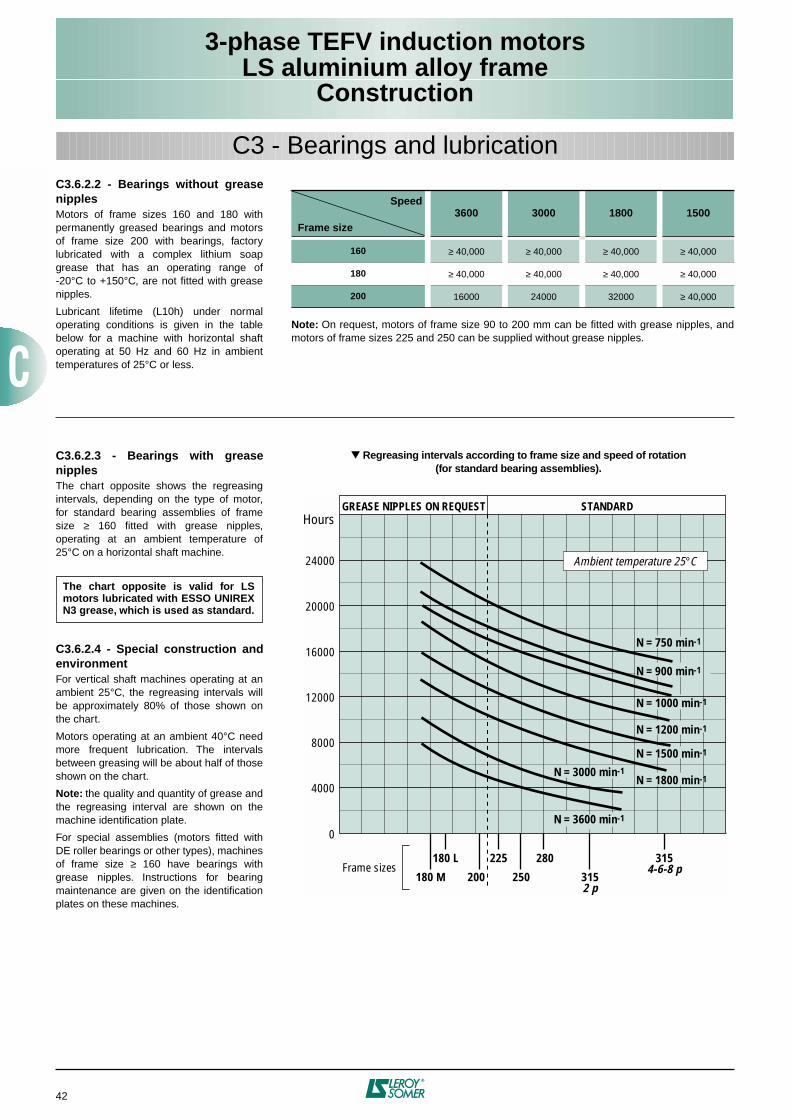
3-phase TEFV induction motorsLS aluminium alloy frame
Construction
42
C3 - Bearings and lubrication
C3.6.2.3 - Bearings with greasenipplesThe chart opposite shows the regreasingintervals, depending on the type of motor,for standard bearing assemblies of framesize ≥ 160 fitted with grease nipples,operating at an ambient temperature of25°C on a horizontal shaft machine.
C3.6.2.4 - Special construction andenvironmentFor vertical shaft machines operating at anambient 25°C, the regreasing intervals willbe approximately 80% of those shown onthe chart.
Motors operating at an ambient 40°C needmore frequent lubrication. The intervalsbetween greasing will be about half of thoseshown on the chart.
Note: the quality and quantity of grease andthe regreasing interval are shown on themachine identification plate.
For special assemblies (motors fitted withDE roller bearings or other types), machinesof frame size ≥ 160 have bearings withgrease nipples. Instructions for bearingmaintenance are given on the identificationplates on these machines.
The chart opposite is valid for LSmotors lubricated with ESSO UNIREXN3 grease, which is used as standard.
Regreasing intervals according to frame size and speed of rotation(for standard bearing assemblies).
0
4000
8000
12000
16000
20000
24000
Hours
N = 3000 min-1
N = 3600 min-1
N = 900 min-1
N = 750 min-1
N = 1200 min-1
N = 1500 min-1
N = 1800 min-1
N = 1000 min-1
Ambient temperature 25°C
180 M
180 L
200
225
250
280
3152 p
3154-6-8 pFrame sizes
GREASE NIPPLES ON REQUEST STANDARD
Note: On request, motors of frame size 90 to 200 mm can be fitted with grease nipples, andmotors of frame sizes 225 and 250 can be supplied without grease nipples.
Speed
Frame size3600 3000 1800 1500
160 ≥ 40,000 ≥ 40,000 ≥ 40,000 ≥ 40,000
180 ≥ 40,000 ≥ 40,000 ≥ 40,000 ≥ 40,000
200 16000 24000 32000 ≥ 40,000
C3.6.2.2 - Bearings without greasenipplesMotors of frame sizes 160 and 180 withpermanently greased bearings and motorsof frame size 200 with bearings, factorylubricated with a complex lithium soapgrease that has an operating range of-20°C to +150°C, are not fitted with greasenipples.
Lubricant lifetime (L10h) under normaloperating conditions is given in the tablebelow for a machine with horizontal shaftoperating at 50 Hz and 60 Hz in ambienttemperatures of 25°C or less.
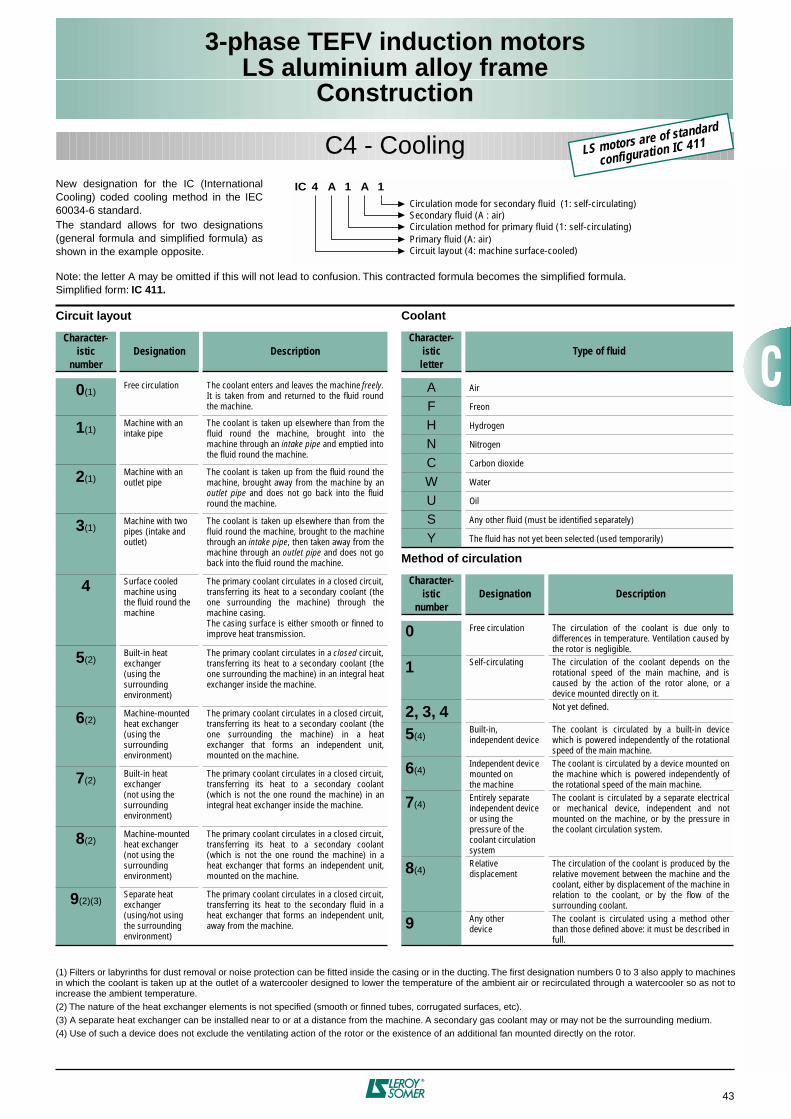
3-phase TEFV induction motorsLS aluminium alloy frame
Construction
43
C4 - CoolingNew designation for the IC (InternationalCooling) coded cooling method in the IEC60034-6 standard.The standard allows for two designations(general formula and simplified formula) asshown in the example opposite.
Note: the letter A may be omitted if this will not lead to confusion. This contracted formula becomes the simplified formula.Simplified form: IC 411.
IC 4 A 1 1
Circulation mode for secondary fluid (1: self-circulating)Secondary fluid (A : air)
Primary fluid (A: air)Circulation method for primary fluid (1: self-circulating)
Circuit layout (4: machine surface-cooled)
A
Circuit layout
Character-istic
numberDesignation Description
0(1)Free circulation The coolant enters and leaves the machine freely.
It is taken from and returned to the fluid roundthe machine.
1(1)Machine with anintake pipe
The coolant is taken up elsewhere than from thefluid round the machine, brought into themachine through an intake pipe and emptied intothe fluid round the machine.
2(1)Machine with anoutlet pipe
The coolant is taken up from the fluid round themachine, brought away from the machine by anoutlet pipe and does not go back into the fluidround the machine.
3(1)Machine with twopipes (intake and outlet)
The coolant is taken up elsewhere than from thefluid round the machine, brought to the machinethrough an intake pipe, then taken away from themachine through an outlet pipe and does not goback into the fluid round the machine.
4 Surface cooled machine using the fluid round the machine
The primary coolant circulates in a closed circuit,transferring its heat to a secondary coolant (theone surrounding the machine) through themachine casing.The casing surface is either smooth or finned toimprove heat transmission.
5(2)Built-in heat exchanger (using the surrounding environment)
The primary coolant circulates in a closed circuit,transferring its heat to a secondary coolant (theone surrounding the machine) in an integral heatexchanger inside the machine.
6(2)Machine-mounted heat exchanger(using the surrounding environment)
The primary coolant circulates in a closed circuit,transferring its heat to a secondary coolant (theone surrounding the machine) in a heatexchanger that forms an independent unit,mounted on the machine.
7(2)Built-in heat exchanger (not using the surrounding environment)
The primary coolant circulates in a closed circuit,transferring its heat to a secondary coolant(which is not the one round the machine) in anintegral heat exchanger inside the machine.
8(2)Machine-mounted heat exchanger(not using thesurrounding environment)
The primary coolant circulates in a closed circuit,transferring its heat to a secondary coolant(which is not the one round the machine) in aheat exchanger that forms an independent unit,mounted on the machine.
9(2)(3)Separate heat exchanger(using/not using the surrounding environment)
The primary coolant circulates in a closed circuit,transferring its heat to the secondary fluid in aheat exchanger that forms an independent unit,away from the machine.
Coolant
Method of circulation
Character-isticletter
Type of fluid
A Air
F Freon
H Hydrogen
N Nitrogen
C Carbon dioxide
W Water
U Oil
S Any other fluid (must be identified separately)
Y The fluid has not yet been selected (used temporarily)
Character-istic
numberDesignation Description
0 Free circulation The circulation of the coolant is due only todifferences in temperature. Ventilation caused bythe rotor is negligible.
1 Self-circulating The circulation of the coolant depends on therotational speed of the main machine, and iscaused by the action of the rotor alone, or adevice mounted directly on it.
2, 3, 4 Not yet defined.
5(4)Built-in, independent device
The coolant is circulated by a built-in devicewhich is powered independently of the rotationalspeed of the main machine.
6(4)Independent device mounted onthe machine
The coolant is circulated by a device mounted onthe machine which is powered independently ofthe rotational speed of the main machine.
7(4)Entirely separate independent device or using the pressure of the coolant circulation system
The coolant is circulated by a separate electricalor mechanical device, independent and notmounted on the machine, or by the pressure inthe coolant circulation system.
8(4)Relative displacement
The circulation of the coolant is produced by therelative movement between the machine and thecoolant, either by displacement of the machine inrelation to the coolant, or by the flow of thesurrounding coolant.
9 Any other device
The coolant is circulated using a method otherthan those defined above: it must be described infull.
(1) Filters or labyrinths for dust removal or noise protection can be fitted inside the casing or in the ducting. The first designation numbers 0 to 3 also apply to machinesin which the coolant is taken up at the outlet of a watercooler designed to lower the temperature of the ambient air or recirculated through a watercooler so as not toincrease the ambient temperature.(2) The nature of the heat exchanger elements is not specified (smooth or finned tubes, corrugated surfaces, etc).(3) A separate heat exchanger can be installed near to or at a distance from the machine. A secondary gas coolant may or may not be the surrounding medium.(4) Use of such a device does not exclude the ventilating action of the rotor or the existence of an additional fan mounted directly on the rotor.
LS motors are of standard
configuration IC 411
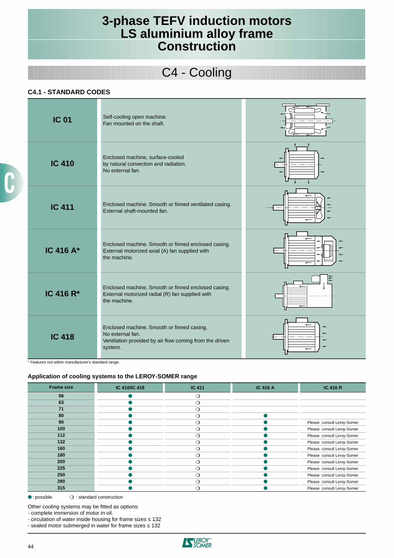
3-phase TEFV induction motorsLS aluminium alloy frame
Construction
44
C4.1 - STANDARD CODES
* Features not within manufacturer’s standard range.
IC 01 Self-cooling open machine.Fan mounted on the shaft.
IC 410Enclosed machine, surface-cooledby natural convection and radiation.No external fan.
IC 411 Enclosed machine. Smooth or finned ventilated casing.External shaft-mounted fan.
IC 416 A*Enclosed machine. Smooth or finned enclosed casing.External motorized axial (A) fan supplied withthe machine.
IC 416 R*Enclosed machine. Smooth or finned enclosed casing.External motorized radial (R) fan supplied withthe machine.
IC 418Enclosed machine. Smooth or finned casing.No external fan.Ventilation provided by air flow coming from the driven system.
C4 - Cooling
Application of cooling systems to the LEROY-SOMER range
: possible. : standard construction
Other cooling systems may be fitted as options:- complete immersion of motor in oil.- circulation of water inside housing for frame sizes ≤ 132- sealed motor submerged in water for frame sizes ≤ 132
Frame size IC 410/IC 418 IC 411 IC 416 A IC 416 R
56
63
71
80
90 Please consult Leroy-Somer
100 Please consult Leroy-Somer
112 Please consult Leroy-Somer
132 Please consult Leroy-Somer
160 Please consult Leroy-Somer
180 Please consult Leroy-Somer
200 Please consult Leroy-Somer
225 Please consult Leroy-Somer
250 Please consult Leroy-Somer
280 Please consult Leroy-Somer
315 Please consult Leroy-Somer
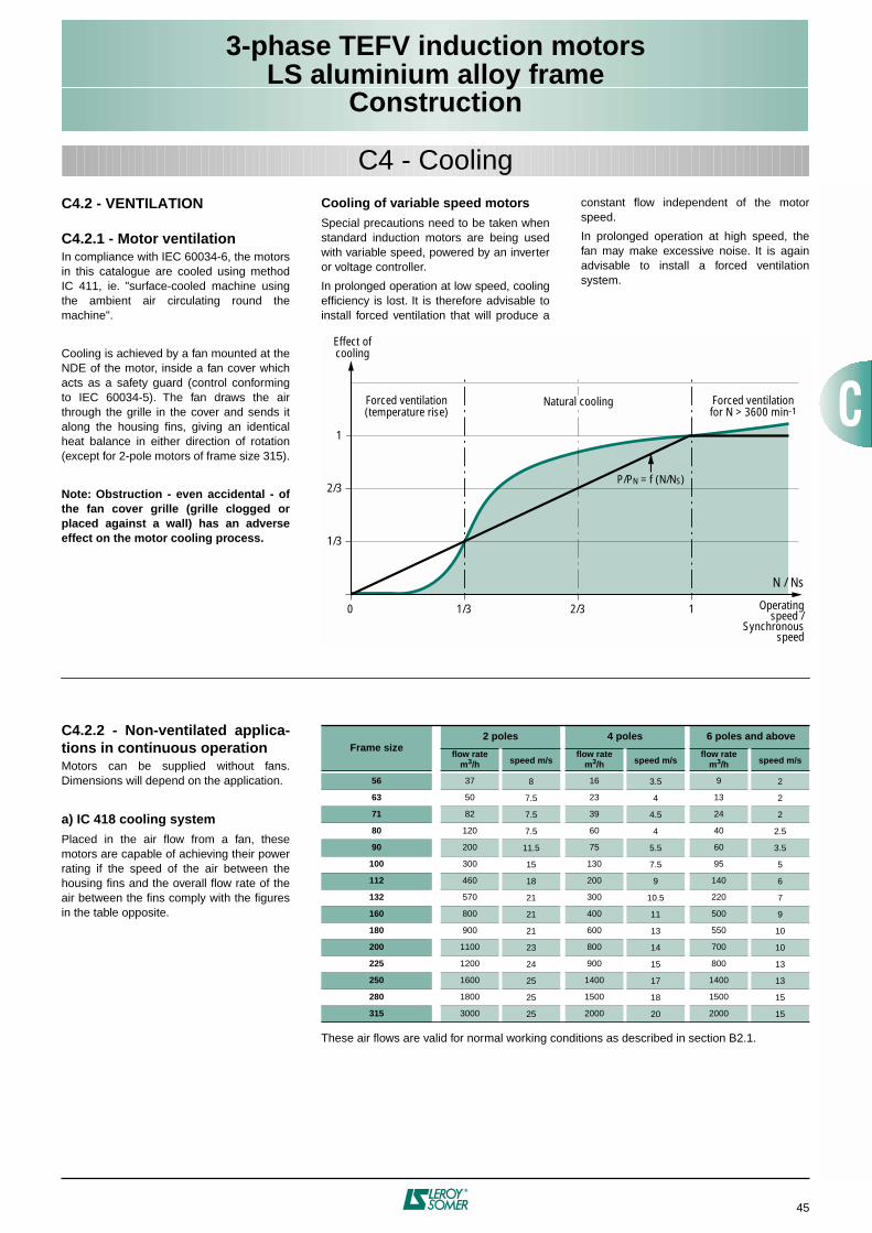
3-phase TEFV induction motorsLS aluminium alloy frame
Construction
45
C4 - CoolingC4.2 - VENTILATION
C4.2.1 - Motor ventilationIn compliance with IEC 60034-6, the motorsin this catalogue are cooled using methodIC 411, ie. "surface-cooled machine usingthe ambient air circulating round themachine".
Cooling is achieved by a fan mounted at theNDE of the motor, inside a fan cover whichacts as a safety guard (control conformingto IEC 60034-5). The fan draws the airthrough the grille in the cover and sends italong the housing fins, giving an identicalheat balance in either direction of rotation(except for 2-pole motors of frame size 315).
Note: Obstruction - even accidental - ofthe fan cover grille (grille clogged orplaced against a wall) has an adverseeffect on the motor cooling process.
Cooling of variable speed motorsSpecial precautions need to be taken whenstandard induction motors are being usedwith variable speed, powered by an inverteror voltage controller.
In prolonged operation at low speed, coolingefficiency is lost. It is therefore advisable toinstall forced ventilation that will produce a
constant flow independent of the motorspeed.
In prolonged operation at high speed, thefan may make excessive noise. It is againadvisable to install a forced ventilationsystem.
1/3
2/3
1
0 1/3 2/3 1
N / Ns
Forced ventilation(temperature rise)
Natural cooling Forced ventilationfor N > 3600 min-1
Operatingspeed /
Synchronousspeed
Effect ofcooling
P/PN = f (N/NS)
C4.2.2 - Non-ventilated applica-tions in continuous operationMotors can be supplied without fans.Dimensions will depend on the application.
a) IC 418 cooling systemPlaced in the air flow from a fan, thesemotors are capable of achieving their powerrating if the speed of the air between thehousing fins and the overall flow rate of theair between the fins comply with the figuresin the table opposite.
These air flows are valid for normal working conditions as described in section B2.1.
Frame size2 poles 4 poles 6 poles and above
flow rate m3/h speed m/s
flow rate m3/h speed m/s
flow rate m3/h speed m/s
56 37 8 16 3.5 9 2
63 50 7.5 23 4 13 2
71 82 7.5 39 4.5 24 2
80 120 7.5 60 4 40 2.5
90 200 11.5 75 5.5 60 3.5
100 300 15 130 7.5 95 5
112 460 18 200 9 140 6
132 570 21 300 10.5 220 7
160 800 21 400 11 500 9
180 900 21 600 13 550 10
200 1100 23 800 14 700 10
225 1200 24 900 15 800 13
250 1600 25 1400 17 1400 13
280 1800 25 1500 18 1500 15
315 3000 25 2000 20 2000 15
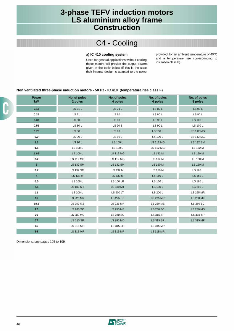
3-phase TEFV induction motorsLS aluminium alloy frame
Construction
46
C4 - Coolinga) IC 410 cooling systemUsed for general applications without cooling,these motors will provide the output powersgiven in the table below (if this is the case,their internal design is adapted to the power
provided, for an ambient temperature of 40°Cand a temperature rise corresponding toinsulation class F).
Non ventilated three-phase induction motors - 50 Hz - IC 410 (temperature rise class F)
Dimensions: see pages 105 to 109
PowerkW
No. of poles2 poles
No. of poles4 poles
No. of poles6 poles
No. of poles8 poles
0.18 LS 71 L LS 71 L LS 80 L LS 90 L
0.25 LS 71 L LS 80 L LS 80 L LS 90 L
0.37 LS 80 L LS 80 L LS 90 L LS 100 L
0.55 LS 80 L LS 90 S LS 90 L LS 100 L
0.75 LS 80 L LS 90 L LS 100 L LS 112 MG
0.9 LS 90 L LS 90 L LS 100 L LS 112 MG
1.1 LS 90 L LS 100 L LS 112 MG LS 132 SM
1.5 LS 100 L LS 100 L LS 112 MG LS 132 M
1.85 LS 100 L LS 112 MG LS 132 M LS 160 M
2.2 LS 112 MG LS 112 MG LS 132 M LS 160 M
3 LS 132 SM LS 132 SM LS 160 M LS 160 M
3.7 LS 132 SM LS 132 M LS 160 M LS 160 L
4 LS 132 M LS 132 M LS 160 L LS 160 L
5.5 LS 160 L LS 160 LR LS 160 L LS 180 L
7.5 LS 180 MT LS 180 MT LS 180 L LS 200 L
11 LS 200 L LS 200 LT LS 200 L LS 225 MR
15 LS 225 MR LS 225 ST LS 225 MR LS 250 MK
18.5 LS 250 MZ LS 225 MR LS 250 ME LS 280 SC
22 LS 280 SC LS 250 ME LS 280 SC LS 280 MD
30 LS 280 MC LS 280 SC LS 315 SP LS 315 SP
37 LS 315 SP LS 280 MD LS 315 SP LS 315 MP
45 LS 315 MP LS 315 SP LS 315 MP -
55 LS 315 MR LS 315 MR LS 315 MR -

3-phase TEFV induction motorsLS aluminium alloy frame
Construction
47
C5 - Mains connectionC5.1 - TERMINAL BOXPlaced as standard on the top of the motornear the drive end, the terminal box hasIP 55 protection and is fitted with a cablegland (see table in C5.2).
The standard position of the cable gland ison the right, seen from the drive end, but,owing to the symmetrical construction of thebox, it can be placed in any of the 4directions (except position 2 on flange-mounted motors).
If required, the terminal box may be fitted ina different position (on the left or right asseen from the drive end, and at the DE orNDE of the motor housing).
Positions of the terminal box in relation to the drive end
(motor in IM 1001 position)
Positions of the cable glandin relation to the drive end
2
4
13
A
BD
Standardposition
Standardpositionon delivery(adjustable)
Position 2 not recommendedand it is not possible on standard
(FF) flange-mounted motor
Terminal box for 71 frame Terminal box for 80 to 112 frame Terminal box for 200 to 315 frame
C5.1.1 - Flying leadsAccording to specification, motors can besupplied with flying leads or multicorecables. Please state cable characteristics(type and supplier, cross-section, length,number of conductors), connection method(on stator coil end turns, or on a separatepanel), and the cable gland positionrequired.
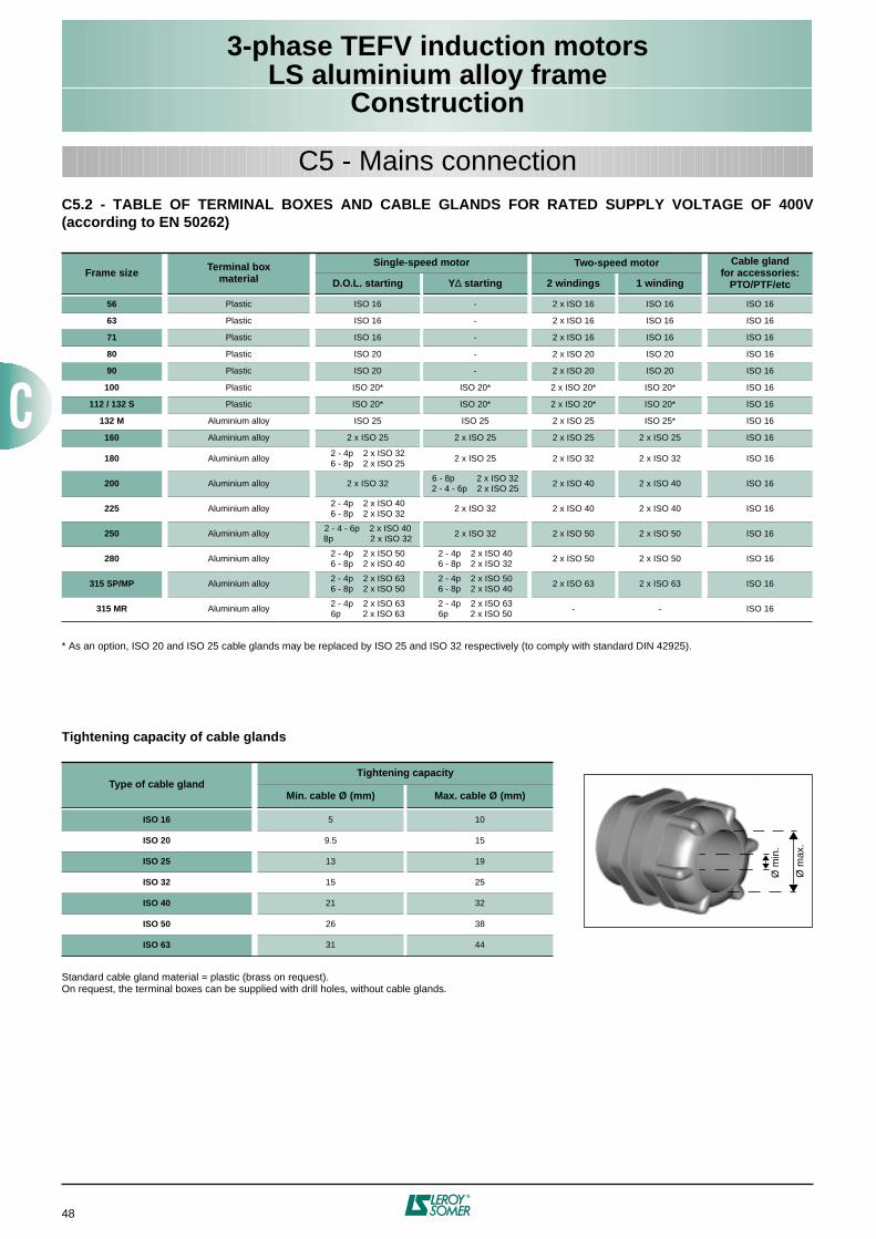
3-phase TEFV induction motorsLS aluminium alloy frame
Construction
48
C5 - Mains connectionC5.2 - TABLE OF TERMINAL BOXES AND CABLE GLANDS FOR RATED SUPPLY VOLTAGE OF 400V(according to EN 50262)
* As an option, ISO 20 and ISO 25 cable glands may be replaced by ISO 25 and ISO 32 respectively (to comply with standard DIN 42925).
Frame size Terminal boxmaterial
Single-speed motor Two-speed motor Cable glandfor accessories:
PTO/PTF/etcD.O.L. starting Y∆ starting 2 windings 1 winding
56 Plastic ISO 16 - 2 x ISO 16 ISO 16 ISO 16
63 Plastic ISO 16 - 2 x ISO 16 ISO 16 ISO 16
71 Plastic ISO 16 - 2 x ISO 16 ISO 16 ISO 16
80 Plastic ISO 20 - 2 x ISO 20 ISO 20 ISO 16
90 Plastic ISO 20 - 2 x ISO 20 ISO 20 ISO 16
100 Plastic ISO 20* ISO 20* 2 x ISO 20* ISO 20* ISO 16
112 / 132 S Plastic ISO 20* ISO 20* 2 x ISO 20* ISO 20* ISO 16
132 M Aluminium alloy ISO 25 ISO 25 2 x ISO 25 ISO 25* ISO 16
160 Aluminium alloy 2 x ISO 25 2 x ISO 25 2 x ISO 25 2 x ISO 25 ISO 16
180 Aluminium alloy2 - 4p 2 x ISO 326 - 8p 2 x ISO 25
2 x ISO 25 2 x ISO 32 2 x ISO 32 ISO 16
200 Aluminium alloy 2 x ISO 326 - 8p 2 x ISO 322 - 4 - 6p 2 x ISO 25
2 x ISO 40 2 x ISO 40 ISO 16
225 Aluminium alloy2 - 4p 2 x ISO 406 - 8p 2 x ISO 32
2 x ISO 32 2 x ISO 40 2 x ISO 40 ISO 16
250 Aluminium alloy2 - 4 - 6p 2 x ISO 408p 2 x ISO 32
2 x ISO 32 2 x ISO 50 2 x ISO 50 ISO 16
280 Aluminium alloy2 - 4p 2 x ISO 506 - 8p 2 x ISO 40
2 - 4p 2 x ISO 406 - 8p 2 x ISO 32
2 x ISO 50 2 x ISO 50 ISO 16
315 SP/MP Aluminium alloy2 - 4p 2 x ISO 636 - 8p 2 x ISO 50
2 - 4p 2 x ISO 506 - 8p 2 x ISO 40
2 x ISO 63 2 x ISO 63 ISO 16
315 MR Aluminium alloy2 - 4p 2 x ISO 636p 2 x ISO 63
2 - 4p 2 x ISO 636p 2 x ISO 50
- - ISO 16
Tightening capacity of cable glands
Standard cable gland material = plastic (brass on request).On request, the terminal boxes can be supplied with drill holes, without cable glands.
Type of cable glandTightening capacity
Min. cable Ø (mm) Max. cable Ø (mm)
ISO 16 5 10
ISO 20 9.5 15
ISO 25 13 19
ISO 32 15 25
ISO 40 21 32
ISO 50 26 38
ISO 63 31 44
Ø m
ax.
Ø m
in.
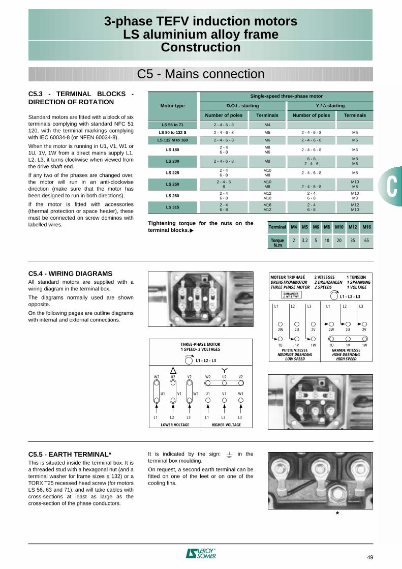
3-phase TEFV induction motorsLS aluminium alloy frame
Construction
49
C5.3 - TERMINAL BLOCKS -DIRECTION OF ROTATION
Standard motors are fitted with a block of sixterminals complying with standard NFC 51120, with the terminal markings complyingwith IEC 60034-8 (or NFEN 60034-8).
When the motor is running in U1, V1, W1 or1U, 1V, 1W from a direct mains supply L1,L2, L3, it turns clockwise when viewed fromthe drive shaft end.
If any two of the phases are changed over,the motor will run in an anti-clockwisedirection (make sure that the motor hasbeen designed to run in both directions).
If the motor is fitted with accessories(thermal protection or space heater), thesemust be connected on screw dominos withlabelled wires.
C5 - Mains connection
C5.4 - WIRING DIAGRAMSAll standard motors are supplied with awiring diagram in the terminal box.
The diagrams normally used are shownopposite.
On the following pages are outline diagramswith internal and external connections.
THREE-PHASE MOTOR1 SPEED- 2 VOLTAGES
L1 - L2 - L3
W2 U2 V2
L1 L2 L3
U1 V1 W1
LOWER VOLTAGE
W2 U2 V2
L1 L2 L3
U1 V1 W1
HIGHER VOLTAGE
L1 - L2 - L3
MOTEUR TRIPHASÉDREHSTROMMOTORTHREE PHASE MOTOR
2 VITESSES2 DREHZAHLEN2 SPEEDS
1 TENSION1 SPANNUNG1 VOLTAGE
PETITE VITESSENIEDRIGE DREHZAHL
LOW SPEED
2W 2U 2V
L1 L2 L3
1U 1V 1WGRANDE VITESSEHOHE DREHZAHL
HIGH SPEED
DAHLANDER∆ /YY & Y/YY
2W 2U 2V
L1 L2 L3
1U 1V 1W
C5.5 - EARTH TERMINAL*This is situated inside the terminal box. It isa threaded stud with a hexagonal nut (and aterminal washer for frame sizes ≤ 132) or aTORX T25 recessed head screw (for motorsLS 56, 63 and 71), and will take cables withcross-sections at least as large as thecross-section of the phase conductors.
It is indicated by the sign: in theterminal box moulding.
On request, a second earth terminal can befitted on one of the feet or on one of thecooling fins.
Motor type
Single-speed three-phase motor
D.O.L. starting Y / ∆ starting
Number of poles Terminals Number of poles Terminals
LS 56 to 71 2 - 4 - 6 - 8 M4
LS 80 to 132 S 2 - 4 - 6 - 8 M5 2 - 4 - 6 - 8 M5
LS 132 M to 160 2 - 4 - 6 - 8 M6 2 - 4 - 6 - 8 M6
LS 180 2 - 46 - 8
M8M6
2 - 4 - 6 - 8 M6
LS 200 2 - 4 - 6 - 8 M86 - 8
2 - 4 - 6M8M6
LS 225 2 - 46 - 8
M10M8
2 - 4 - 6 - 8 M8
LS 250 2 - 4 - 68
M10M8 2 - 4 - 6 - 8
M10M8
LS 280 2 - 46 - 8
M12M10
2 - 46 - 8
M10M8
LS 315 2 - 46 - 8
M16M12
2 - 46 - 8
M12M10
Tightening torque for the nuts on theterminal blocks.
Terminal M4 M5 M6 M8 M10 M12 M16
Torque N.m
2 3.2 5 10 20 35 65
*
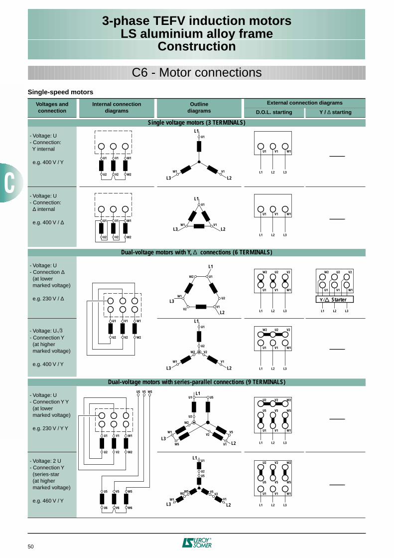
3-phase TEFV induction motorsLS aluminium alloy frame
Construction
50
Single-speed motors
Voltages andconnection
Internal connectiondiagrams
Outlinediagrams
External connection diagrams
D.O.L. starting Y / ∆ starting
Single voltage motors (3 TERMINALS)
- Voltage: U- Connection: Y internal
e.g. 400 V / Y
- Voltage: U- Connection: ∆ internal
e.g. 400 V / ∆
Dual-voltage motors with Y, ∆ connections (6 TERMINALS)
- Voltage: U- Connection ∆ (at lower marked voltage)
e.g. 230 V / ∆
- Voltage: U- Connection Y (at higher marked voltage)
e.g. 400 V / Y
Dual-voltage motors with series-parallel connections (9 TERMINALS)
- Voltage: U- Connection Y Y (at lower marked voltage)
e.g. 230 V / Y Y
- Voltage: 2 U - Connection Y (series-star (at higher marked voltage)
e.g. 460 V / Y
3
C6 - Motor connections
U1 V1
W1U2 V2 W2
U1
V1
L1
L3 L2L3L2L1
W1V1U1
U1 V1W1
U2 V2 W2
U1
V1
L1
L3 L2L3L2L1
W1V1U1
W1
W1
U1 V1
U2 V2 W2
W1
U1 V1
U2 V2 W2
W1
U5 V5
U6 V6 W6
W5
U5 V5 W5
W1
U1
U2
L1
L3
L2 L3L2L1
W1V1U1
L3L2L1
W1V1U1
W1
U1
V2
L1
L3 L2
U2
W2
V1
V2U2W2 V2U2W2
W1
U1
L3
U2
W2
V2
W5
U5
V1
L1
L2
V5
W1
U1
V1
L1
L3 L2
U2U5
W5W2 V2
V5
W2
V2V1
L3L2L1
W1V1U1
W5V5U5
L3L2L1
W1V1U1
V2U2W2
L3L2L1
W1V1U1
W2 V2U2
W5V5U5
W2 V2U2
Y Starter
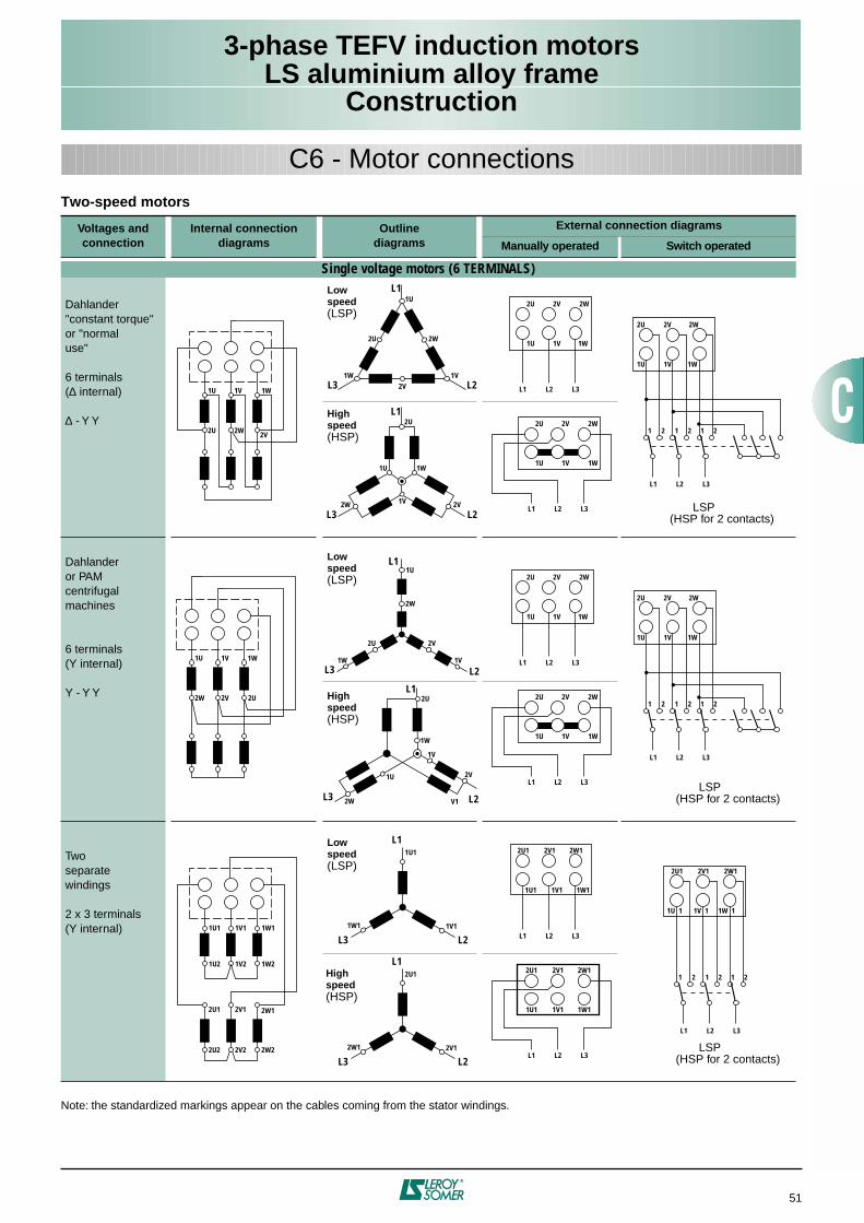
3-phase TEFV induction motorsLS aluminium alloy frame
Construction
51
Two-speed motors
Note: the standardized markings appear on the cables coming from the stator windings.
Voltages andconnection
Internal connection diagrams
Outlinediagrams
External connection diagrams
Manually operated Switch operated
Single voltage motors (6 TERMINALS)
Dahlander"constant torque"or "normaluse"
6 terminals(∆ internal)
∆ - Y Y
Dahlanderor PAMcentrifugalmachines
6 terminals(Y internal)
Y - Y Y
Twoseparatewindings
2 x 3 terminals(Y internal)
C6 - Motor connections
L3L2L1
1W1V1U
1W
2U
1V
L1
L3 L21U 1V
2U 2W 2V
1W
1U1 1V1
1U2 1V2 1W2
1W1
2U1 2V1
2U2 2V2 2W2
2W1
1W1
1U1
L1
L3 L21V1
L3
1W
1U
1V
2W
2U
V1
L1
L2
2V
2W
1U
2V
2W2V2U
2W
1W
L3
2U
1V
L1
1U
2VL2
L3L2L1
1W1V1U
2W2V2U
L3L2L1
1W1V1U
2W2V2U
1 2 1 2 1 2
1U 1V
2W 2V
1W
2U
1W
1U
1V
L1
L3 L2
2W
2U 2V
2W1
2U1
L1
L3 L22V1
L3L2L1
1W1V1U
2W2V2U
L3L2L1
1W1V1U
2W2V2U
L3L2L1
1W1V1U
2W2V2U
1 2 1 2 1 2
L3L2L1
1W11V11U1
2W12V12U1
L3L2L1
1W11V11U1
2W12V12U1
L3L2L1
1W 11V 11U 1
2W12V12U1
1 2 1 2 1 2
Lowspeed(LSP)
Highspeed(HSP)
Lowspeed(LSP)
Highspeed(HSP)
Lowspeed(LSP)
Highspeed(HSP)
LSP(HSP for 2 contacts)
LSP(HSP for 2 contacts)
LSP(HSP for 2 contacts)
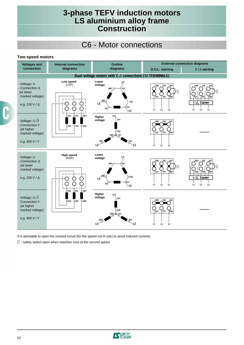
3-phase TEFV induction motorsLS aluminium alloy frame
Construction
52
C6 - Motor connectionsTwo-speed motors
It is advisable to open the unused circuit (for the speed not in use) to avoid induced currents.
➊ : safety switch open when machine runs at the second speed.
Voltages andconnection
Internal connectiondiagrams
Outlinediagrams
External connection diagrams
D.O.L. starting Y / ∆ starting
Dual-voltage motors with Y, ∆ connections (12 TERMINALS)
- Voltage: U- Connection ∆ (at lower marked voltage)
e.g. 230 V / ∆
- Voltage: U- Connection Y (at higher marked voltage)
e.g. 400 V / Y
- Voltage: U- Connection ∆ (at lower marked voltage)
e.g. 230 V / ∆
- Voltage: U- Connection Y (at higher marked voltage)
e.g. 400 V / Y
3
3
1U1 1V1
1U2 1V2 1W2
1W1
1W1
1U1
1U2
L1
L3
L2 L3L2L1
1W11V11U1
L3L2L1
1W11V11U1
1W1
1U1
1V1
L1
L3 L2
1U2
1W2
1V2
1V21U21W2 1V21U21W21W2
1V21V1
L3L2L1
1W11V11U1
1V21U21W2
2U1 2V1
2U2 2V2 2W2
2W1
2W1
2U1
2U2
L1
L3
L2 L3L2L1
2W12V12U1
L3L2L1
2W12V12U1
2W1
2U1
2V1
L1
L3 L2
2U2
2W2
2V2
2V22U22W2 2V22U22W22W2
2V22V1
L3L2L1
2W12V12U1
2V22U22W2
➊
➊
➊
➊
Y Starter
Y Starter
Lowervoltage
Highervoltage
Lowervoltage
Highervoltage
Low speed(LSP)
High speed(HSP)
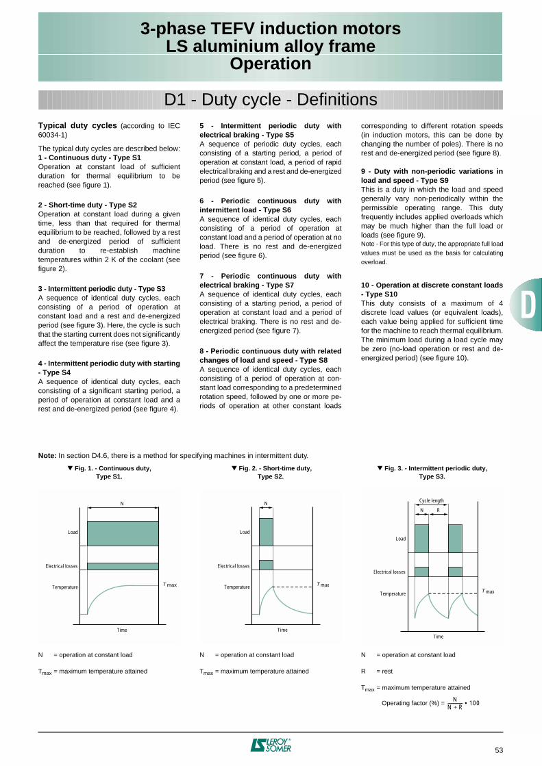
3-phase TEFV induction motorsLS aluminium alloy frame
Operation
53
Typical duty cycles
(according to IEC60034-1)
The typical duty cycles are described below:
1 - Continuous duty - Type S1
Operation at constant load of sufficientduration for thermal equilibrium to bereached (see figure 1).
2 - Short-time duty - Type S2
Operation at constant load during a giventime, less than that required for thermalequilibrium to be reached, followed by a restand de-energized period of sufficientduration to re-establish machinetemperatures within 2 K of the coolant (seefigure 2).
3 - Intermittent periodic duty - Type S3
A sequence of identical duty cycles, eachconsisting of a period of operation atconstant load and a rest and de-energizedperiod (see figure 3). Here, the cycle is suchthat the starting current does not significantlyaffect the temperature rise (see figure 3).
4 - Intermittent periodic duty with starting- Type S4
A sequence of identical duty cycles, eachconsisting of a significant starting period, aperiod of operation at constant load and arest and de-energized period (see figure 4).
5 - Intermittent periodic duty withelectrical braking - Type S5
A sequence of periodic duty cycles, eachconsisting of a starting period, a period ofoperation at constant load, a period of rapidelectrical braking and a rest and de-energizedperiod (see figure 5).
6 - Periodic continuous duty withintermittent load - Type S6
A sequence of identical duty cycles, eachconsisting of a period of operation atconstant load and a period of operation at noload. There is no rest and de-energizedperiod (see figure 6).
7 - Periodic continuous duty withelectrical braking - Type S7
A sequence of identical duty cycles, eachconsisting of a starting period, a period ofoperation at constant load and a period ofelectrical braking. There is no rest and de-energized period (see figure 7).
8 - Periodic continuous duty with relatedchanges of load and speed - Type S8
A sequence of identical duty cycles, eachconsisting of a period of operation at con-stant load corresponding to a predeterminedrotation speed, followed by one or more pe-riods of operation at other constant loads
corresponding to different rotation speeds(in induction motors, this can be done bychanging the number of poles). There is norest and de-energized period (see figure 8).
9 - Duty with non-periodic variations inload and speed - Type S9
This is a duty in which the load and speedgenerally vary non-periodically within thepermissible operating range. This dutyfrequently includes applied overloads whichmay be much higher than the full load orloads (see figure 9).
Note - For this type of duty, the appropriate full loadvalues must be used as the basis for calculatingoverload.
10 - Operation at discrete constant loads- Type S10
This duty consists of a maximum of 4discrete load values (or equivalent loads),each value being applied for sufficient timefor the machine to reach thermal equilibrium.The minimum load during a load cycle maybe zero (no-load operation or rest and de-energized period) (see figure 10).
D1 - Duty cycle - Definitions
N = operation at constant load
T
max
= maximum temperature attained
N = operation at constant load
T
max
= maximum temperature attained
N = operation at constant load
R = rest
T
max
= maximum temperature attained
Operating factor (%) = N
N R+-------------- 100•
Fig. 1. - Continuous duty,Type S1.
Fig. 2. - Short-time duty,Type S2.
Fig. 3. - Intermittent periodic duty,Type S3.
Load
Electrical losses
Temperature
Time
N
T max
Load
Electrical losses
Temperature
Time
N
T max
Load
Electrical losses
Temperature
Time
N
T max
R
Cycle length
Note:
In section D4.6, there is a method for specifying machines in intermittent duty.
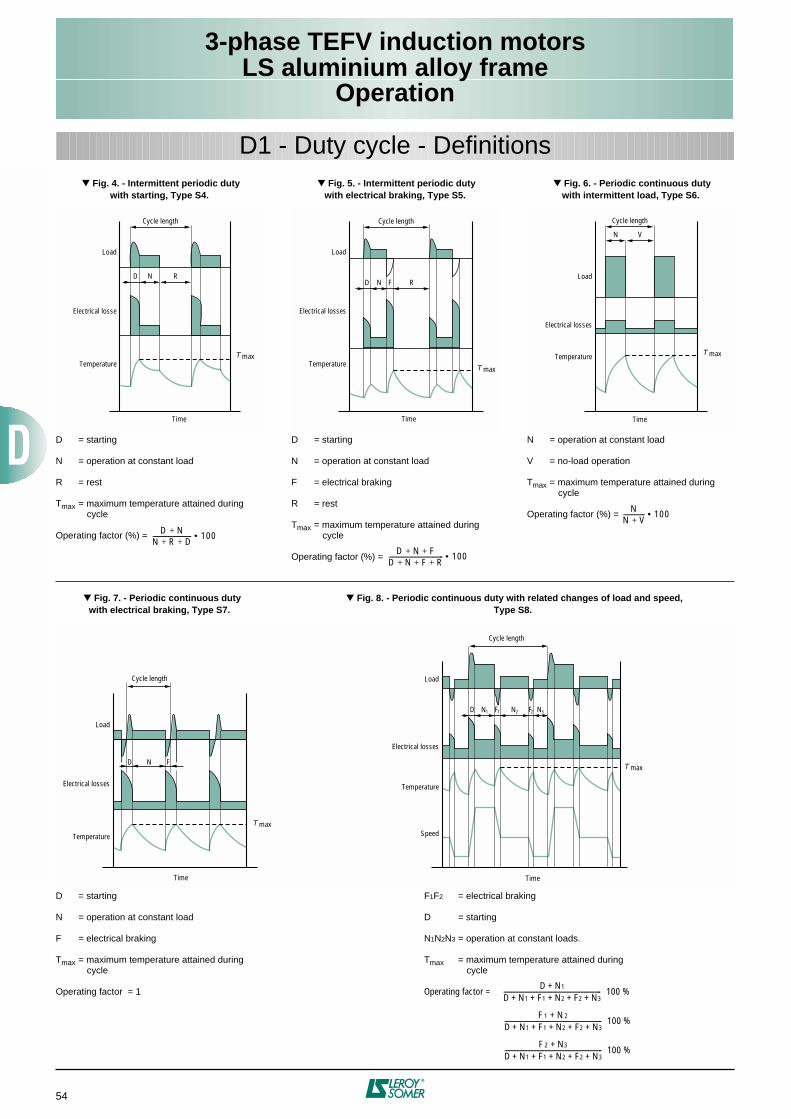
3-phase TEFV induction motorsLS aluminium alloy frame
Operation
54
D1 - Duty cycle - Definitions
Fig. 4. - Intermittent periodic dutywith starting, Type S4.
Fig. 5. - Intermittent periodic dutywith electrical braking, Type S5.
Fig. 6. - Periodic continuous dutywith intermittent load, Type S6.
D = starting
N = operation at constant load
R = rest
T
max
= maximum temperature attained duringcycle
Operating factor (%) =
D = starting
N = operation at constant load
F = electrical braking
R = rest
T
max
= maximum temperature attained duringcycle
Operating factor (%) =
N = operation at constant load
V = no-load operation
T
max
= maximum temperature attained duringcycle
Operating factor (%) =
D N+N R D+ +------------------------- 100•
D N F+ +D N F R+ + +----------------------------------- 100•
NN V+-------------- 100•
Fig. 7. - Periodic continuous dutywith electrical braking, Type S7.
Fig. 8. - Periodic continuous duty with related changes of load and speed,Type S8.
F
1
F
2
= electrical braking
D = starting
N
1
N
2
N
3
= operation at constant loads.
T
max
= maximum temperature attained duringcycle
Operating factor = 100 %
100 %
100 %
D N1+D N1 F1 N2 F2 N3+ + + + +---------------------------------------------------------------
F1 N2+D N1 F1 N2 F2 N3+ + + + +---------------------------------------------------------------
F2 N3+D N1 F1 N2 F2 N3+ + + + +---------------------------------------------------------------
D = starting
N = operation at constant load
F = electrical braking
T
max
= maximum temperature attained duringcycle
Operating factor = 1
Load
Electrical losse
Temperature
Time
N
T max
R
Cycle length
D
Load
Electrical losses
Temperature
Time
N
T max
R
Cycle length
D FLoad
Electrical losses
Temperature
Time
N
T max
V
Cycle length
Load
Electrical losses
Temperature
Time
N
T max
F
Cycle length
D
Load
Electrical losses
Temperature
Time
N1
T max
N2
Cycle length
D
Speed
F1 F2 N3
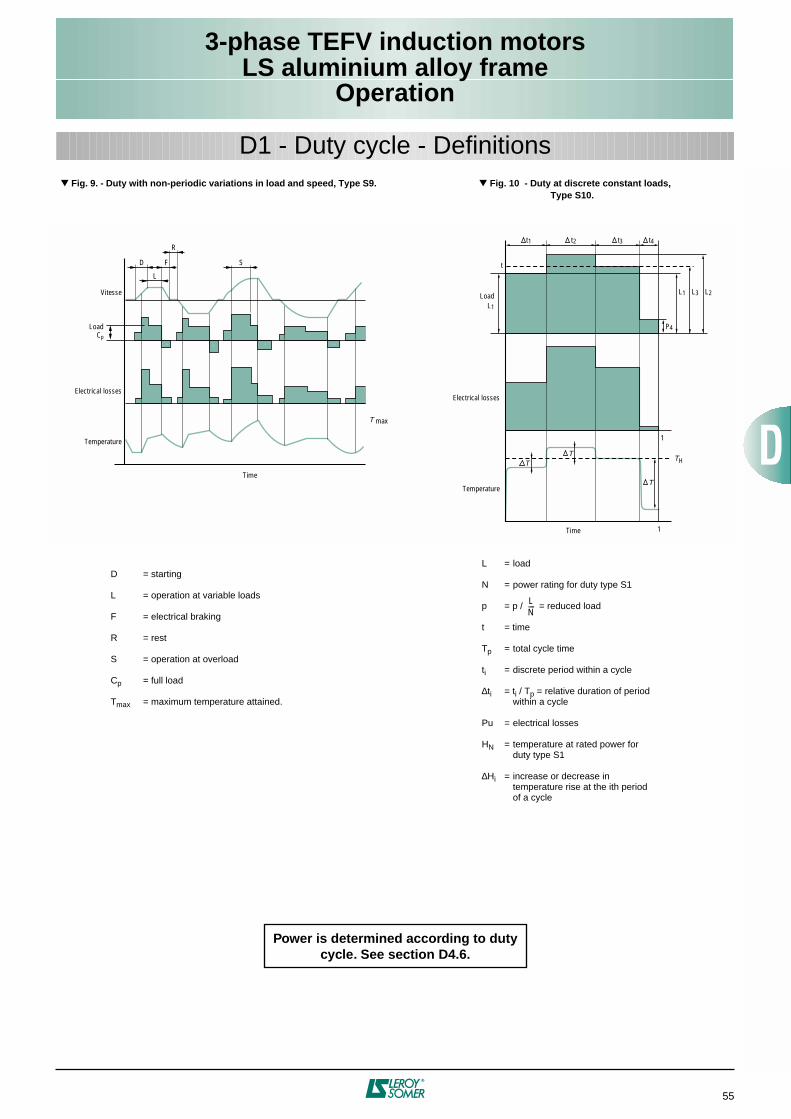
3-phase TEFV induction motorsLS aluminium alloy frame
Operation
55
D1 - Duty cycle - Definitions
Fig. 9. - Duty with non-periodic variations in load and speed, Type S9.
Fig. 10 - Duty at discrete constant loads,Type S10.
D = starting
L = operation at variable loads
F = electrical braking
R = rest
S = operation at overload
C
p
= full load
T
max
= maximum temperature attained.
L = load
N = power rating for duty type S1
p = p / = reduced load
t = time
T
p
= total cycle time
t
i
= discrete period within a cycle
∆
t
i
= t
i
/ T
p
= relative duration of periodwithin a cycle
Pu = electrical losses
H
N
= temperature at rated power forduty type S1
∆
H
i
= increase or decrease intemperature rise at the ith periodof a cycle
LN----
Vitesse
Electrical losses
Temperature
Time
T max
L
LoadCp
FD
R
S
1
TT
T
TH
Temperature
1
Electrical losses
t1
t
LoadL1
L2L3
t2 t3 t4
P4
Time
L1
Power is determined according to duty cycle. See section D4.6.
3-phase TEFV induction motorsLS aluminium alloy frame
Operation
56
D2.1 - REGULATIONS ANDSTANDARDS
The statement by the electricity consultativecommittee dated 25th June 1982, and the 6thedition (1983) of publication No. 38 of theInternational Electrotechnical Committee (IEC)have laid down time scales for theharmonisation of standard voltages in Europe.
Since 1998, voltages at the point of deliveryhave to be maintained between the followingextreme values:
• Single-phase current: 207 to 244 V • Three-phase current: 358 to 423 V
The IEC 60038 standard gives theEuropean reference voltage as 230 / 400 Vthree-phase and 230 V single-phase, with atolerance of +6% to -10% until 2003 and±10% from then on.
The tolerances usually permitted for powersupply sources are indicated below:
• Maximum line drop between customerdelivery point and customer usage point:4%.
• Variation in frequency around nominalfrequency:- continuous state : ±1%- transient state : ±2%
• Three-phase mains phase-balance error:- zero-sequence component and/or negativephase sequence component compared topositive phase sequence component: < 2%
• Harmonics:- relative harmonic content: <10%- individual harmonic voltages: to beestablished• Surges and transient power cuts: to beestablished
The motors in this catalogue aredesigned for use on the European powersupply of 230 / 400 V ±10% - 50 Hz.
This means that the same motor canoperate on the following existing supplies: - 220 / 380 V ±5%- 230 / 400 V ±5% and ±10%- 240 / 415 V ± 5%and is therefore suitable for a large numberof countries worldwide where for example itis possible to extend them to some 60 Hzsupplies:-265 / 460 V ± 10%
From 2008, 380 and 415 V - 50 Hz voltagesupplies must be eliminated.
D2 - Supply voltage
Publication 38
Sixth edition
INTERNATIONAL ELECTROTECHNICAL COMMISSION
IEC STANDARD
230 / 400V
IEC standard voltages
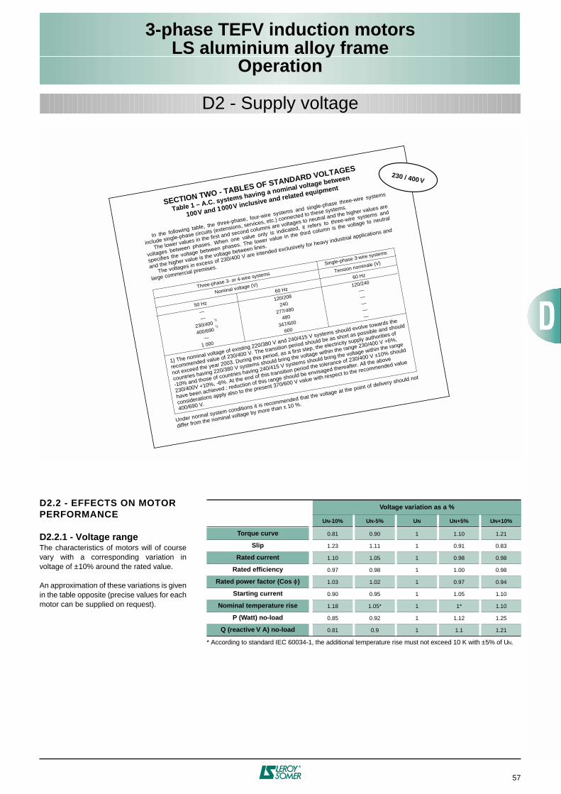
3-phase TEFV induction motorsLS aluminium alloy frame
Operation
57
D2.2 - EFFECTS ON MOTOR PERFORMANCE
D2.2.1 - Voltage range
The characteristics of motors will of coursevary with a corresponding variation involtage of ±10% around the rated value.
An approximation of these variations is givenin the table opposite (precise values for eachmotor can be supplied on request).
D2 - Supply voltage
In the following table, the three-phase, four-wire systems and single-phase three-wire systems
include single-phase circuits (extensions, services, etc.) connected to these systems.
The lower values in the first and second columns are voltages to neutral and the higher values are
voltages between phases. When one value only is indicated, it refers to three-wire systems and
specifies the voltage between phases. The lower value in the third column is the voltage to neutral
and the higher value is the voltage between lines.
The voltages in excess of 230/400 V are intended exclusively for heavy industrial applications and
large commercial premises.
SECTION TWO - TABLES OF STANDARD VOLTAGES
Table 1 – A.C. systems having a nominal voltage between
100V and 1000V inclusive and related equipment
Three-phase 3- or 4-wire systems
Nominal voltage (V)
Single-phase 3-wire systems
Tension nominale (V)
60 Hz
120/240
—————
1) The nominal voltage of existing 220/380 V and 240/415 V systems should evolve towards the
recommended value of 230/400 V. The transition period should be as short as possible and should
not exceed the year 2003. During this period, as a first step, the electricity supply authorities of
countries having 220/380 V systems should bring the voltage within the range 230/400 V +6%,
-10% and those of countries having 240/415 V systems should bring the voltage within the range
230/400V +10%, -6%. At the end of this transition period the tolerance of 230/400 V ±10% should
have been achieved ; reduction of this range should be envisaged thereafter. All the above
considerations apply also to the present 370/600 V value with respect to the recommended value
400/690 V.
230 / 400 V
50 Hz
——
230/400
400/690
—1 000
60 Hz
120/208
240
277/480
480
347/600
600
1)
1)
Under normal system conditions it is recommended that the voltage at the point of delivery should not
differ from the nominal voltage by more than ± 10 %.
* According to standard IEC 60034-1, the additional temperature rise must not exceed 10 K with ±5% of U
N
.
Voltage variation as a %
U
N
-10% U
N
-5% U
N
U
N
+5% U
N
+10%
Torque curve
0.81 0.90 1 1.10 1.21
Slip
1.23 1.11 1 0.91 0.83
Rated current
1.10 1.05 1 0.98 0.98
Rated efficiency
0.97 0.98 1 1.00 0.98
Rated power factor (Cos
ϕ
)
1.03 1.02 1 0.97 0.94
Starting current
0.90 0.95 1 1.05 1.10
Nominal temperature rise
1.18 1.05* 1 1* 1.10
P (Watt) no-load
0.85 0.92 1 1.12 1.25
Q (reactive V A) no-load
0.81 0.9 1 1.1 1.21
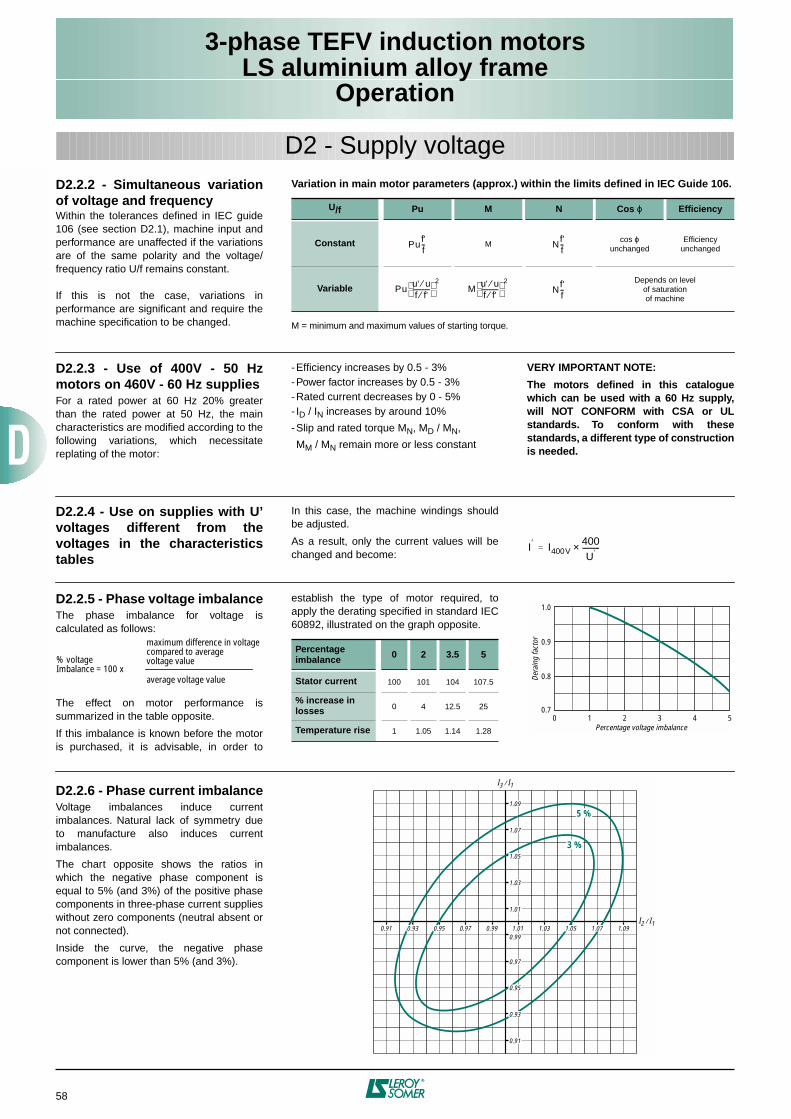
3-phase TEFV induction motorsLS aluminium alloy frame
Operation
58
D2.2.2 - Simultaneous variationof voltage and frequency
Within the tolerances defined in IEC guide106 (see section D2.1), machine input andperformance are unaffected if the variationsare of the same polarity and the voltage/frequency ratio U/f remains constant.
If this is not the case, variations inperformance are significant and require themachine specification to be changed.
D2 - Supply voltage
Variation in main motor parameters (approx.) within the limits defined in IEC Guide 106.
M = minimum and maximum values of starting torque.
U/f Pu M N Cos
ϕ
Efficiency
Constant
Mcos
ϕ
unchangedEfficiency
unchanged
VariableDepends on level
of saturationof machine
Puf'f-- N
f'f--
Puu' u⁄f f'⁄-----------
2M
u' u⁄f f'⁄-----------
2
Nf'f--
D2.2.3 - Use of 400V - 50 Hzmotors on 460V - 60 Hz suppliesFor a rated power at 60 Hz 20% greaterthan the rated power at 50 Hz, the maincharacteristics are modified according to thefollowing variations, which necessitatereplating of the motor:
-Efficiency increases by 0.5 - 3%-Power factor increases by 0.5 - 3%-Rated current decreases by 0 - 5%- ID / IN increases by around 10%
-Slip and rated torque MN, MD / MN,
MM / MN remain more or less constant
VERY IMPORTANT NOTE:
The motors defined in this cataloguewhich can be used with a 60 Hz supply,will NOT CONFORM with CSA or ULstandards. To conform with thesestandards, a different type of constructionis needed.
D2.2.4 - Use on supplies with U’voltages different from thevoltages in the characteristicstables
In this case, the machine windings shouldbe adjusted.
As a result, only the current values will bechanged and become:
I′ I400V400U′-----------×=
D2.2.5 - Phase voltage imbalanceThe phase imbalance for voltage iscalculated as follows:
The effect on motor performance issummarized in the table opposite.
If this imbalance is known before the motoris purchased, it is advisable, in order to
establish the type of motor required, toapply the derating specified in standard IEC60892, illustrated on the graph opposite.
% voltageImbalance = 100 x
maximum difference in voltagecompared to averagevoltage value
average voltage value
Percentage imbalance 0 2 3.5 5
Stator current 100 101 104 107.5
% increase inlosses 0 4 12.5 25
Temperature rise 1 1.05 1.14 1.28
0 1 2 3 4 5
0.8
0.9
1.0
0.7
Percentage voltage imbalance
Dera
ing
fact
or
D2.2.6 - Phase current imbalanceVoltage imbalances induce currentimbalances. Natural lack of symmetry dueto manufacture also induces currentimbalances.
The chart opposite shows the ratios inwhich the negative phase component isequal to 5% (and 3%) of the positive phasecomponents in three-phase current supplieswithout zero components (neutral absent ornot connected).
Inside the curve, the negative phasecomponent is lower than 5% (and 3%).
0.91
0.97
0.99
1.01
1.03
1.07
1.09
0.990.970.91 1.091.031.01I2 / I1
I3 / I1
5 %
3 %
0.93
0.95
1.071.050.950.93
1.05
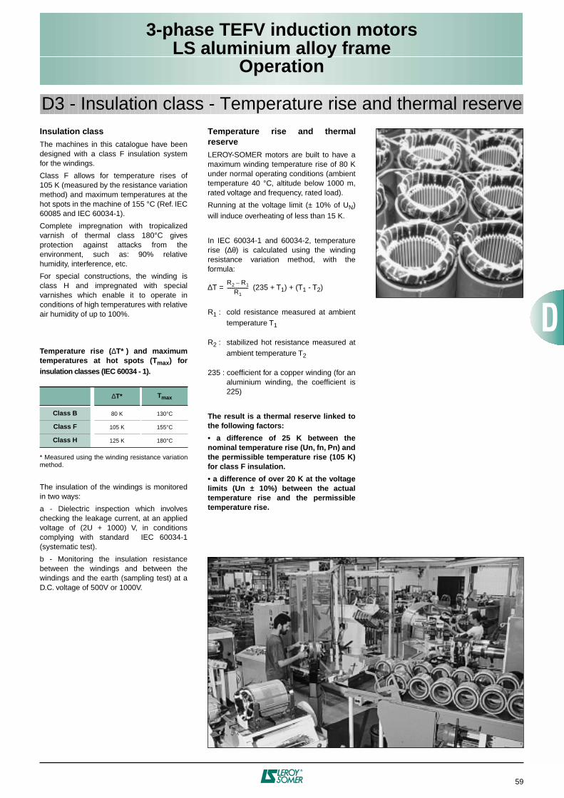
3-phase TEFV induction motorsLS aluminium alloy frame
Operation
59
Insulation classThe machines in this catalogue have beendesigned with a class F insulation systemfor the windings.
Class F allows for temperature rises of105 K (measured by the resistance variationmethod) and maximum temperatures at thehot spots in the machine of 155 °C (Ref. IEC60085 and IEC 60034-1).
Complete impregnation with tropicalizedvarnish of thermal class 180°C givesprotection against attacks from theenvironment, such as: 90% relativehumidity, interference, etc.
For special constructions, the winding isclass H and impregnated with specialvarnishes which enable it to operate inconditions of high temperatures with relativeair humidity of up to 100%.
Temperature rise (∆T* ) and maximumtemperatures at hot spots (Tmax) forinsulation classes (IEC 60034 - 1).
* Measured using the winding resistance variationmethod.
The insulation of the windings is monitoredin two ways:
a - Dielectric inspection which involveschecking the leakage current, at an appliedvoltage of (2U + 1000) V, in conditionscomplying with standard IEC 60034-1(systematic test).
b - Monitoring the insulation resistancebetween the windings and between thewindings and the earth (sampling test) at aD.C. voltage of 500V or 1000V.
Temperature rise and thermalreserveLEROY-SOMER motors are built to have amaximum winding temperature rise of 80 Kunder normal operating conditions (ambienttemperature 40 °C, altitude below 1000 m,rated voltage and frequency, rated load).
Running at the voltage limit (± 10% of UN)will induce overheating of less than 15 K.
In IEC 60034-1 and 60034-2, temperaturerise (∆θ) is calculated using the windingresistance variation method, with theformula:
∆T = (235 + T1) + (T1 - T2)
R1 : cold resistance measured at ambienttemperature T1
R2 : stabilized hot resistance measured atambient temperature T2
235 : coefficient for a copper winding (for analuminium winding, the coefficient is225)
The result is a thermal reserve linked tothe following factors:
• a difference of 25 K between thenominal temperature rise (Un, fn, Pn) andthe permissible temperature rise (105 K)for class F insulation.
• a difference of over 20 K at the voltagelimits (Un ± 10%) between the actualtemperature rise and the permissibletemperature rise.
∆T* Tmax
Class B 80 K 130°C
Class F 105 K 155°C
Class H 125 K 180°C
R2 R1–
R1-------------------
D3 - Insulation class - Temperature rise and thermal reserve
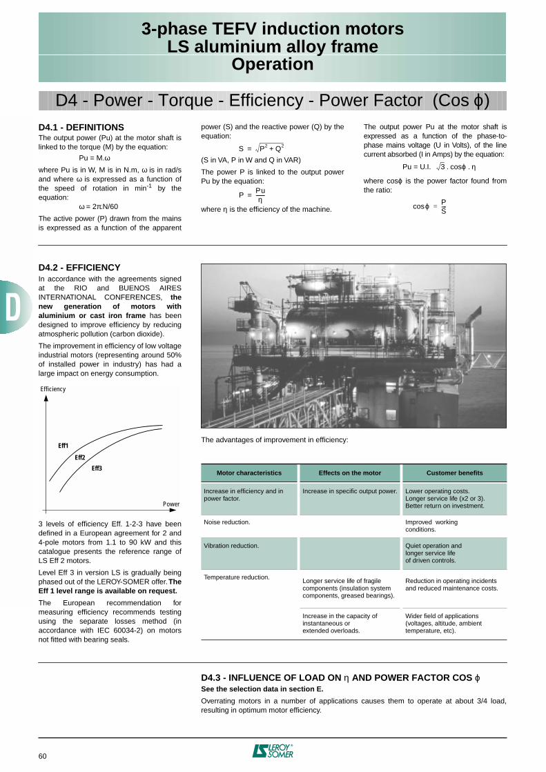
3-phase TEFV induction motorsLS aluminium alloy frame
Operation
60
D4.1 - DEFINITIONSThe output power (Pu) at the motor shaft islinked to the torque (M) by the equation:
Pu = M.ωwhere Pu is in W, M is in N.m, ω is in rad/sand where ω is expressed as a function ofthe speed of rotation in min-1 by theequation:
ω = 2π.N/60
The active power (P) drawn from the mainsis expressed as a function of the apparent
power (S) and the reactive power (Q) by theequation:
(S in VA, P in W and Q in VAR)
The power P is linked to the output powerPu by the equation:
where η is the efficiency of the machine.
The output power Pu at the motor shaft isexpressed as a function of the phase-to-phase mains voltage (U in Volts), of the linecurrent absorbed (I in Amps) by the equation:
Pu = U.I. . cosϕ . η
where cosϕ is the power factor found fromthe ratio:
S P2 Q2+=
PPuη-------=
3
ϕcos PS----=
D4 - Power - Torque - Efficiency - Power Factor (Cos ϕ)
D4.2 - EFFICIENCYIn accordance with the agreements signedat the RIO and BUENOS AIRESINTERNATIONAL CONFERENCES, thenew generation of motors withaluminium or cast iron frame has beendesigned to improve efficiency by reducingatmospheric pollution (carbon dioxide).
The improvement in efficiency of low voltageindustrial motors (representing around 50%of installed power in industry) has had alarge impact on energy consumption.
3 levels of efficiency Eff. 1-2-3 have beendefined in a European agreement for 2 and4-pole motors from 1.1 to 90 kW and thiscatalogue presents the reference range ofLS Eff 2 motors.
Level Eff 3 in version LS is gradually beingphased out of the LEROY-SOMER offer. TheEff 1 level range is available on request.
The European recommendation formeasuring efficiency recommends testingusing the separate losses method (inaccordance with IEC 60034-2) on motorsnot fitted with bearing seals.
Efficiency
Eff1
Eff2
Eff3
Power
The advantages of improvement in efficiency:
Motor characteristics Effects on the motor Customer benefits
Increase in efficiency and in power factor.
Increase in specific output power. Lower operating costs.Longer service life (x2 or 3).Better return on investment.
Noise reduction. Improved workingconditions.
Vibration reduction. Quiet operation andlonger service lifeof driven controls.
Temperature reduction. Longer service life of fragile components (insulation system components, greased bearings).
Reduction in operating incidents and reduced maintenance costs.
Increase in the capacity of instantaneous orextended overloads.
Wider field of applications(voltages, altitude, ambient temperature, etc).
D4.3 - INFLUENCE OF LOAD ON η AND POWER FACTOR COS ϕSee the selection data in section E.
Overrating motors in a number of applications causes them to operate at about 3/4 load,resulting in optimum motor efficiency.
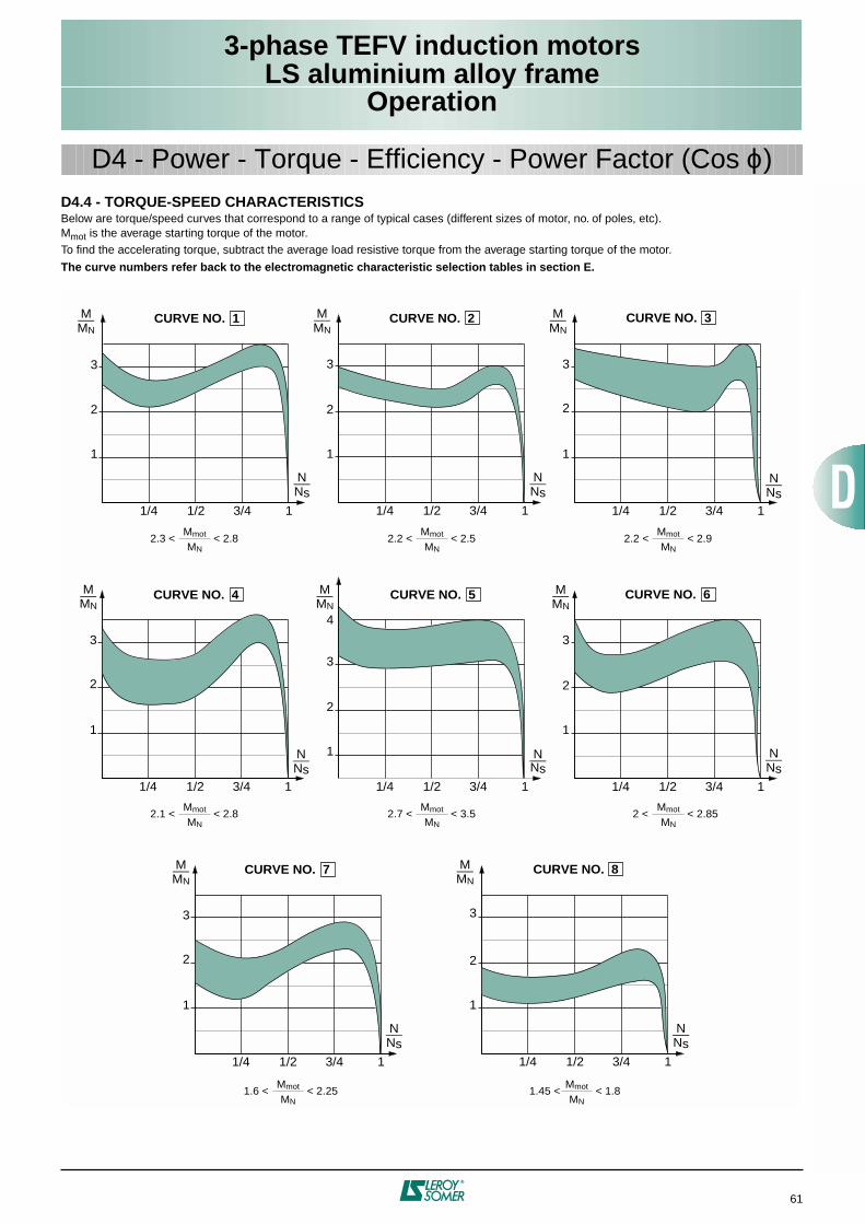
3-phase TEFV induction motorsLS aluminium alloy frame
Operation
61
D4.4 - TORQUE-SPEED CHARACTERISTICSBelow are torque/speed curves that correspond to a range of typical cases (different sizes of motor, no. of poles, etc).Mmot is the average starting torque of the motor.To find the accelerating torque, subtract the average load resistive torque from the average starting torque of the motor.
The curve numbers refer back to the electromagnetic characteristic selection tables in section E.
M_MN
1
2
3
1/4 1/2 3/4 1
N_Ns
M_MN
1
2
3
1/4 1/2 3/4 1
N_Ns
M_MN
1
2
1/4 1/2 3/4 1
N_Ns
CURVE NO. 1 CURVE NO. 2 CURVE NO. 3
M_MN
1
2
3
4
1/4 1/2 3/4 1
N_Ns
M_MN
1
2
3
1/4 1/2 3/4 1
N_Ns
M_MN
1
2
3
1/4 1/2 3/4 1
N_Ns
CURVE NO. 4 CURVE NO. 6CURVE NO. 5
M_MN
1
2
3
1/4 1/2 3/4 1
N_Ns
CURVE NO. 7 M_MN
1
2
1/4 1/2 3/4 1
N_Ns
CURVE NO. 8
3
3
2.3 < < 2.8Mmot
MN2.2 < < 2.5
Mmot
MN2.2 < < 2.9
Mmot
MN
2.1 < < 2.8Mmot
MN2.7 < < 3.5
Mmot
MN
1.6 < < 2.25Mmot
MN1.45 < < 1.8
Mmot
MN
2 < < 2.85Mmot
MN
D4 - Power - Torque - Efficiency - Power Factor (Cos ϕ)
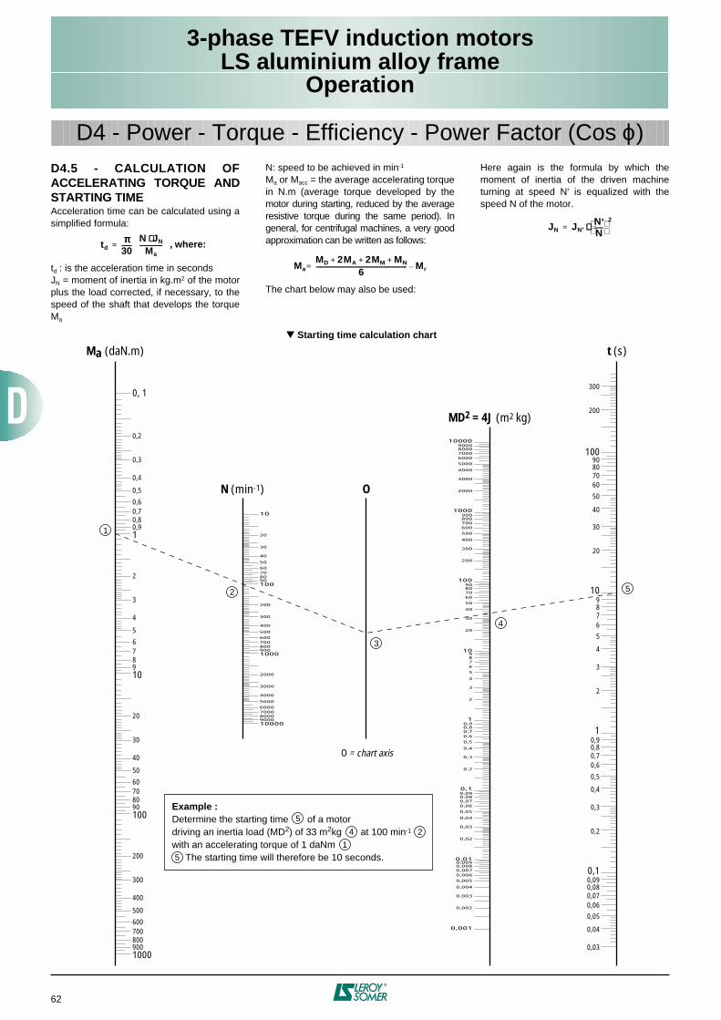
3-phase TEFV induction motorsLS aluminium alloy frame
Operation
62
D4 - Power - Torque - Efficiency - Power Factor (Cos ϕ)
1000900800700600
500
400
300
200
10090807060
50
40
30
20
109876
5
4
3
2
10,90,80,70,6
0,5
0,4
0,3
0,2
0, 1
100009000800070006000
5000
4000
3000
2000
1000900800700600
500
400
300
200
10090807060
50
40
30
20
10
100009000800070006000
5000
4000
3000
2000
1000900800700600
500
400
300
200
10090807060
50
40
30
20
109876
5
4
3
2
10,90,80,70,6
0,5
0,4
0,3
0,2
0,10,090,080,070,06
0,05
0,04
0,03
0,02
0,010,0090,0080,0070,006
0,005
0,004
0,003
0,002
0,001
807060
50
40
30
20
1098765
4
3
2
10,90,80,70,6
0,5
0,4
0,3
0,2
0,10,090,080,070,060,05
0,04
0,03
300
200
10090
Ma (daN.m) t (s)
N (min-1)
MD2 = 4J (m2 kg)
O
O = chart axis
Example :Determine the starting time of a motordriving an inertia load (MD2) of 33 m2kg at 100 min-1
with an accelerating torque of 1 daNm The starting time will therefore be 10 seconds.
5
5
4
4
2
3
2
1
1
5
D4.5 - CALCULATION OFACCELERATING TORQUE ANDSTARTING TIMEAcceleration time can be calculated using asimplified formula:
td : is the acceleration time in secondsJN = moment of inertia in kg.m2 of the motorplus the load corrected, if necessary, to thespeed of the shaft that develops the torqueMa
N: speed to be achieved in min-1
Ma or Macc = the average accelerating torquein N.m (average torque developed by themotor during starting, reduced by the averageresistive torque during the same period). Ingeneral, for centrifugal machines, a very goodapproximation can be written as follows:
The chart below may also be used:
Here again is the formula by which themoment of inertia of the driven machineturning at speed N' is equalized with thespeed N of the motor.
tdππππ
30-------=
N JN⋅⋅⋅⋅Ma
---------------- , where:
MaMD 2MA 2MM MN+ + +
6---------------------------------------------------------------- Mr–=
JN JN ′′′′N ′′′′N------
2⋅⋅⋅⋅=
Starting time calculation chart
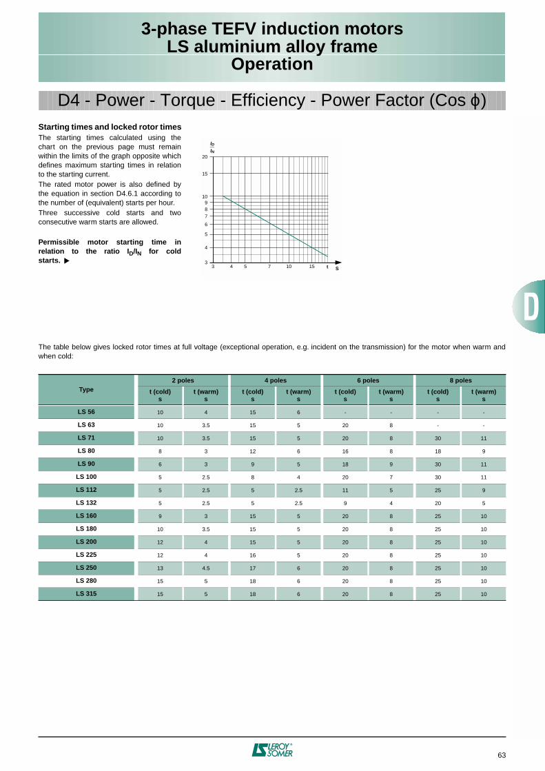
3-phase TEFV induction motorsLS aluminium alloy frame
Operation
63
Starting times and locked rotor timesThe starting times calculated using thechart on the previous page must remainwithin the limits of the graph opposite whichdefines maximum starting times in relationto the starting current.The rated motor power is also defined bythe equation in section D4.6.1 according tothe number of (equivalent) starts per hour.Three successive cold starts and twoconsecutive warm starts are allowed.
Permissible motor starting time inrelation to the ratio ID/IN for coldstarts.
3 4 5 7 10 153
4
5
6
789
10
15
20
ID_IN
St
D4 - Power - Torque - Efficiency - Power Factor (Cos ϕ)
The table below gives locked rotor times at full voltage (exceptional operation, e.g. incident on the transmission) for the motor when warm andwhen cold:
Type2 poles 4 poles 6 poles 8 poles
t (cold)s
t (warm)s
t (cold)s
t (warm)s
t (cold)s
t (warm)s
t (cold)s
t (warm)s
LS 56 10 4 15 6 - - - -
LS 63 10 3.5 15 5 20 8 - -
LS 71 10 3.5 15 5 20 8 30 11
LS 80 8 3 12 6 16 8 18 9
LS 90 6 3 9 5 18 9 30 11
LS 100 5 2.5 8 4 20 7 30 11
LS 112 5 2.5 5 2.5 11 5 25 9
LS 132 5 2.5 5 2.5 9 4 20 5
LS 160 9 3 15 5 20 8 25 10
LS 180 10 3.5 15 5 20 8 25 10
LS 200 12 4 15 5 20 8 25 10
LS 225 12 4 16 5 20 8 25 10
LS 250 13 4.5 17 6 20 8 25 10
LS 280 15 5 18 6 20 8 25 10
LS 315 15 5 18 6 20 8 25 10
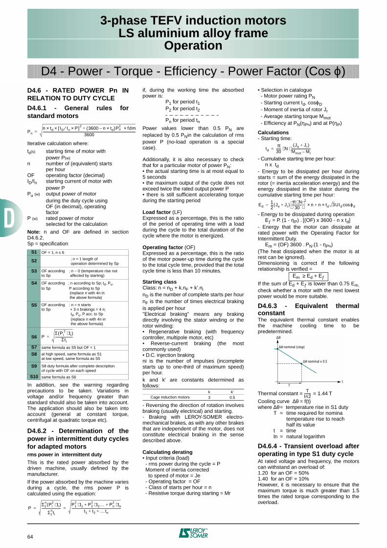
3-phase TEFV induction motorsLS aluminium alloy frame
Operation
64
D4.6 - RATED POWER Pn INRELATION TO DUTY CYCLE
D4.6.1 - General rules forstandard motors
Iterative calculation where:
td(s) starting time of motor withpower P(w)
n number of (equivalent) startsper hour
OF operating factor (decimal)ID/In starting current of motor with
power PPu (w) output power of motor
during the duty cycle usingOF (in decimal), operatingfactor
P (w) rated power of motorselected for the calculation
Note: n and OF are defined in sectionD4.6.2.Sp = specification
In addition, see the warning regardingprecautions to be taken. Variations involtage and/or frequency greater thanstandard should also be taken into account.The application should also be taken intoaccount (general at constant torque,centrifugal at quadratic torque etc).
D4.6.2 - Determination of thepower in intermittent duty cyclesfor adapted motorsrms power in intermittent duty
This is the rated power absorbed by thedriven machine, usually defined by themanufacturer.
If the power absorbed by the machine variesduring a cycle, the rms power P iscalculated using the equation:
if, during the working time the absorbedpower is:
P1 for period t1P2 for period t2
Pn for period tnPower values lower than 0.5 PN arereplaced by 0.5 PNin the calculation of rmspower P (no-load operation is a specialcase).
Additionally, it is also necessary to checkthat for a particular motor of power PN:• the actual starting time is at most equal to5 seconds• the maximum output of the cycle does notexceed twice the rated output power P• there is still sufficient accelerating torqueduring the starting period
Load factor (LF)Expressed as a percentage, this is the ratioof the period of operating time with a loadduring the cycle to the total duration of thecycle where the motor is energized.
Operating factor (OF)Expressed as a percentage, this is the ratioof the motor power-up time during the cycleto the total cycle time, provided that the totalcycle time is less than 10 minutes.
Starting classClass: n = nD + k.nF + k’.ninD is the number of complete starts per hournF is the number of times electrical brakingis applied per hour"Electrical braking" means any brakingdirectly involving the stator winding or therotor winding:• Regenerative braking (with frequencycontroller, multipole motor, etc)• Reverse-current braking (the mostcommonly used)• D.C. injection brakingni is the number of impulses (incompletestarts up to one-third of maximum speed)per hour.k and k’ are constants determined asfollows:
- Reversing the direction of rotation involvesbraking (usually electrical) and starting.- Braking with LEROY-SOMER electro-mechanical brakes, as with any other brakesthat are independent of the motor, does notconstitute electrical braking in the sensedescribed above.
Calculating derating• Input criteria (load) - rms power during the cycle = P Moment of inertia corrected to speed of motor = Je - Operating factor = OF - Class of starts per hour = n - Resistive torque during starting = Mr
• Selection in catalogue - Motor power rating PN - Starting current Id, cosϕD - Moment of inertia of rotor Jr - Average starting torque Mmot - Efficiency at PN(ηPN) and at P(ηP)
Calculations- Starting time:
- Cumulative starting time per hour: n x td- Energy to be dissipated per hour duringstarts = sum of the energy dissipated in therotor (= inertia acceleration energy) and theenergy dissipated in the stator during thecumulative starting time per hour:
- Energy to be dissipated during operation Eƒ = P. (1 - ηP) . [(OF) x 3600 - n x td]- Energy that the motor can dissipate atrated power with the Operating Factor forIntermittent Duty. Em = (OF) 3600 . PN.(1 - ηPN)(The heat dissipated when the motor is atrest can be ignored).Dimensioning is correct if the followingrelationship is verified =
If the sum of Ed + Eƒ is lower than 0.75 Em,check whether a motor with the next lowestpower would be more suitable.
D4.6.3 - Equivalent thermalconstantThe equivalent thermal constant enablesthe machine cooling time to bepredetermined.
Thermal constant = = 1.44 T
Cooling curve ∆θ = f(t)where ∆θ= temperature rise in S1 duty
T = time required for nominatemperature rise to reachhalf its value
t = timeln = natural logarithm
D4.6.4 - Transient overload afteroperating in type S1 duty cycleAt rated voltage and frequency, the motorscan withstand an overload of:1.20 for an OF = 50%1.40 for an OF = 10%However, it is necessary to ensure that themaximum torque is much greater than 1.5times the rated torque corresponding to theoverload.
S1 OF = 1; n ≤ 6
S2 ; n = 1 length of operation determined by Sp
S3 OF according ; n ~ 0 (temperature rise not to Sp affected by starting)
S4 OF according ; n according to Sp; td, Pu,to Sp P according to Sp (replace n with 4n in the above formula)
S5 OF according ; n = n startsto Sp + 3 n brakings = 4 n; td, Pu, P acc. to Sp (replace n with 4n in the above formula)
S6
S7 same formula as S5 but OF = 1
S8 at high speed, same formula as S1at low speed, same formula as S5
S9 S8 duty formula after complete descriptionof cycle with OF on each speed
S10 same formula as S6
Pnn td ID In P×⁄[ ] 2 3600 n td×–( )P2
u fdm×+××3600
--------------------------------------------------------------------------------------------------------------------------=
PΣ Pi
2 ti⋅( )Σti
-----------------------=
PΣ1
n Pi2 ti⋅( )
Σ1nti
-------------------------P1
2 t1 P22 t2… Pn
2 tn⋅+⋅+⋅t1 t2 …tn+ +
-----------------------------------------------------------------= =
k k’Cage induction motors 3 0.5
tdπ30------ N
Je Jr+( )Mmot Mr–-------------------------⋅ ⋅=
Ed12--- Je Jr+( ) π N⋅
30------------
2
n n td×+× 3UId ϕdcos=
Em ≥ Ed + Eƒ
∆θ
∆θ nominal (stop)
∆θ nominal x 0.5
Tt
TIn2---------
D4 - Power - Torque - Efficiency - Power Factor (Cos ϕ)
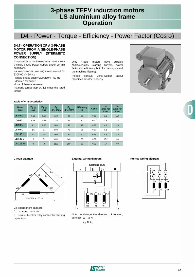
3-phase TEFV induction motorsLS aluminium alloy frame
Operation
65
D4.7 - OPERATION OF A 3-PHASEMOTOR FROM A SINGLE-PHASEPOWER SUPPLY (STEINMETZCONNECTION)It is possible to run three-phase motors froma single-phase power supply under certainconditions:- a low-power (ie. low kW) motor, wound for230/400 V - 50 Hz- single-phase supply 220/230 V - 50 Hz- derated for power- loss of thermal reserve- starting torque approx. 1.5 times the ratedtorque
Only 4-pole motors have suitablecharacteristics (starting current, powerfactor and efficiency, both for the supply andthe machine lifetime).
Please consult Leroy-Somer aboutmachines for other speeds.
D4 - Power - Torque - Efficiency - Power Factor (Cos ϕ)
Table of characteristics
Motortype
P3-phkW
P1-phkW
CDµF - 150V
CpµF - 220V
Efficiency% Cos ϕ
Inamp for
230V
IDamp for
230V
LS 80 L 0.55 0.37 120 30 80 0.91 2.2 11.5
LS 80 L 0.75 0.55 225 32 80 0.91 3.3 18
LS 90 L 1.1 0.75 300 47 79 0.99 4.2 25
LS 90 L 1.5 1.1 500 75 81 0.97 6.1 38
LS 100 L 2.2 1.5 560 90 80 0.98 8.3 45
LS 100 L 3 2.2 650 140 80 0.98 12.2 60
LS 112 M 4 3 1100 250 83 0.92 17 90
Circuit diagram
Cp : permanent capacitorCD : starting capacitorK : circuit breaker relay contact for startingcapacitors
External wiring diagram
Note: to change the direction of rotation,connect W2 to N
V2 to L1
Internal wiring diagram
L1 L2
V2 V1
U2
U1
220 / 230 V - 50 Hz
W1
W2
CD
KCP
W2 U2 V2
U1 V1 W1
L1 J2 J3 N
ELECTRONIC RELAY
CD
Cp
L1 L2
U1 V1
U2 V2 W2
W1
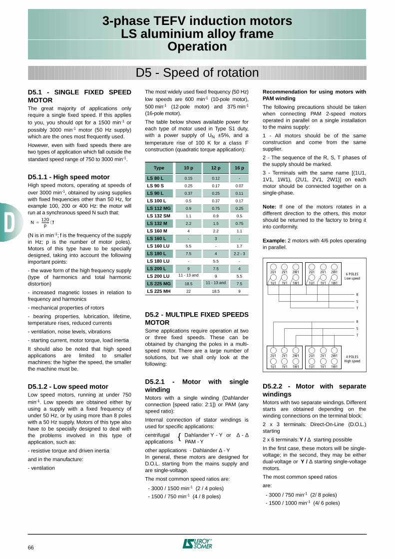
3-phase TEFV induction motorsLS aluminium alloy frame
Operation
66
D5.1 - SINGLE FIXED SPEEDMOTORThe great majority of applications onlyrequire a single fixed speed. If this appliesto you, you should opt for a 1500 min-1 orpossibly 3000 min-1 motor (50 Hz supply)which are the ones most frequently used.
However, even with fixed speeds there aretwo types of application which fall outside thestandard speed range of 750 to 3000 min-1.
D5.1.1 - High speed motorHigh speed motors, operating at speeds ofover 3000 min-1, obtained by using supplieswith fixed frequencies other than 50 Hz, forexample 100, 200 or 400 Hz: the motor willrun at a synchronous speed N such that:
(N is in min-1; f is the frequency of the supplyin Hz; p is the number of motor poles).Motors of this type have to be speciallydesigned, taking into account the followingimportant points:
- the wave form of the high frequency supply(type of harmonics and total harmonicdistortion)
- increased magnetic losses in relation tofrequency and harmonics
- mechanical properties of rotors
- bearing properties, lubrication, lifetime,temperature rises, reduced currents
- ventilation, noise levels, vibrations
- starting current, motor torque, load inertia
It should also be noted that high speedapplications are limited to smallermachines: the higher the speed, the smallerthe machine must be.
D5.1.2 - Low speed motorLow speed motors, running at under 750min-1. Low speeds are obtained either byusing a supply with a fixed frequency ofunder 50 Hz, or by using more than 8 poleswith a 50 Hz supply. Motors of this type alsohave to be specially designed to deal withthe problems involved in this type ofapplication, such as:
- resistive torque and driven inertia
and in the manufacture:
- ventilation
N120p
---------- f⋅=
D5 - Speed of rotation
The most widely used fixed frequency (50 Hz)low speeds are 600 min-1 (10-pole motor),500 min-1 (12-pole motor) and 375 min-1
(16-pole motor).
The table below shows available power foreach type of motor used in Type S1 duty,with a power supply of UN ±5%, and atemperature rise of 100 K for a class Fconstruction (quadratic torque application):
D5.2 - MULTIPLE FIXED SPEEDSMOTORSome applications require operation at twoor three fixed speeds. These can beobtained by changing the poles in a multi-speed motor. There are a large number ofsolutions, but we shall only look at thefollowing:
D5.2.1 - Motor with singlewindingMotors with a single winding (Dahlanderconnection [speed ratio: 2:1]) or PAM (anyspeed ratio):
Internal connection of stator windings isused for specific applications:
centrifugal Dahlander Y - Y or ∆ - ∆applications PAM - Y
other applications - Dahlander ∆ - Y In general, these motors are designed forD.O.L. starting from the mains supply andare single-voltage.
The most common speed ratios are:
- 3000 / 1500 min-1 (2 / 4 poles)
- 1500 / 750 min-1 (4 / 8 poles)
Recommendation for using motors withPAM winding
The following precautions should be takenwhen connecting PAM 2-speed motorsoperated in parallel on a single installationto the mains supply:
1 - All motors should be of the sameconstruction and come from the samesupplier.
2 - The sequence of the R, S, T phases ofthe supply should be marked.
3 - Terminals with the same name [(1U1,1V1, 1W1), (2U1, 2V1, 2W1)] on eachmotor should be connected together on asingle-phase.
Note: If one of the motors rotates in adifferent direction to the others, this motorshould be returned to the factory to bring itinto conformity.
Example: 2 motors with 4/6 poles operatingin parallel.
D5.2.2 - Motor with separatewindingsMotors with two separate windings. Differentstarts are obtained depending on thewinding connections on the terminal block:
2 x 3 terminals: Direct-On-Line (D.O.L.)starting
2 x 6 terminals: Y / ∆ starting possible
In the first case, these motors will be single-voltage; in the second, they may be eitherdual-voltage or Y / ∆ starting single-voltagemotors.
The most common speed ratios
are:
- 3000 / 750 min-1 (2/ 8 poles)
- 1500 / 1000 min-1 (4/ 6 poles)
Type 10 p 12 p 16 p
LS 80 L 0.15 0.12 -
LS 90 S 0.25 0.17 0.07
LS 90 L 0.37 0.25 0.11
LS 100 L 0.5 0.37 0.17
LS 112 MG 0.9 0.75 0.25
LS 132 SM 1.1 0.9 0.5
LS 132 M 2.2 1.5 0.75
LS 160 M 4 2.2 1.1
LS 160 L - 3 -
LS 160 LU 5.5 - 1.7
LS 180 L 7.5 4 2.2 - 3
LS 180 LU - 5.5 -
LS 200 L 9 7.5 4
LS 200 LU 11 - 13 and 9 5.5
LS 225 MG 18.5 11 - 13 and 7.5
LS 225 MH 22 18.5 9
2U1 2V1 2W1
1U1 1V1 1W1
2U1 2V1 2W1
1U1 1V1 1W1
2U1 2V1 2W1
1U1 1V1 1W1
2U1 2V1 2W1
1U1 1V1 1W1
R
6 POLESLow speed
4 POLESHigh speed
T
S
R
T
S
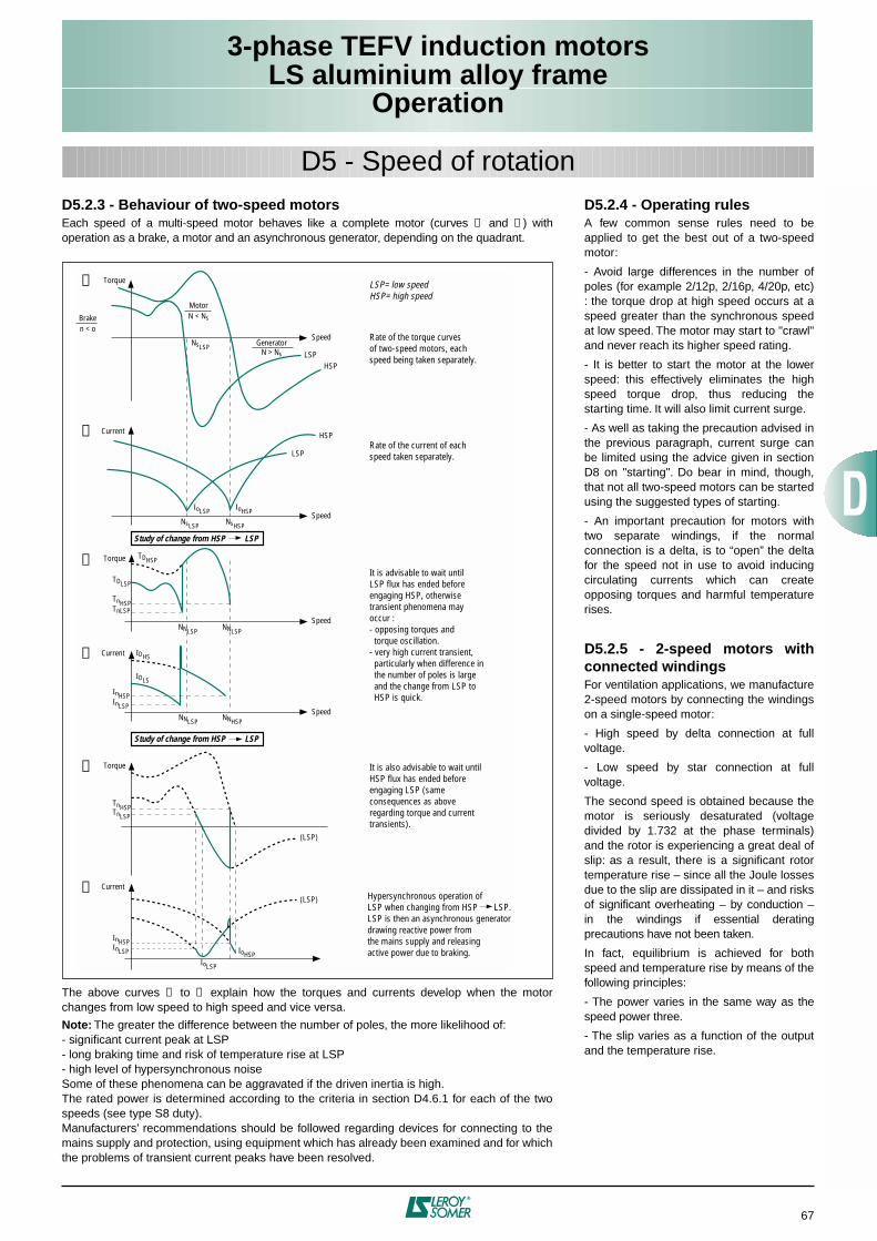
3-phase TEFV induction motorsLS aluminium alloy frame
Operation
67
D5.2.3 - Behaviour of two-speed motorsEach speed of a multi-speed motor behaves like a complete motor (curves ➀ and ➁ ) withoperation as a brake, a motor and an asynchronous generator, depending on the quadrant.
The above curves ➂ to ➅ explain how the torques and currents develop when the motorchanges from low speed to high speed and vice versa.
Note: The greater the difference between the number of poles, the more likelihood of:- significant current peak at LSP- long braking time and risk of temperature rise at LSP- high level of hypersynchronous noiseSome of these phenomena can be aggravated if the driven inertia is high.The rated power is determined according to the criteria in section D4.6.1 for each of the twospeeds (see type S8 duty).Manufacturers’ recommendations should be followed regarding devices for connecting to themains supply and protection, using equipment which has already been examined and for whichthe problems of transient current peaks have been resolved.
➀
➁
➂
➃
➄
➅
InHSP
IoLSP
IoHSPInLSP
Torque
Torque
Torque
Current
Current
Current
Speed
Speed
Speed
Speed
Study of change from HSP LSP
HSP
(LSP)
(LSP)
HSPLSP
LSP= low speedHSP= high speed
Rate of the torque curvesof two-speed motors, each speed being taken separately.
Rate of the current of eachspeed taken separately.
It is advisable to wait untilLSP flux has ended beforeengaging HSP, otherwise transient phenomena may occur :- opposing torques and torque oscillation.- very high current transient, particularly when difference in the number of poles is large and the change from LSP to HSP is quick.
It is also advisable to wait untilHSP flux has ended before engaging LSP (same consequences as aboveregarding torque and currenttransients).
Hypersynchronous operation ofLSP when changing from HSP LSP.LSP is then an asynchronous generatordrawing reactive power fromthe mains supply and releasingactive power due to braking.
NsLSP
NsLSP
TDHSP
NNLSP NNLSP
NNLSP
TDLSP
TnHSPTnLSP
TnHSPTnLSP
InHSP
IDLS
IDHS
InLSP
NNHSP
IoLSP IoHSP
NsHSP
LSP
Braken < o
MotorN < Ns
GeneratorN > Ns
Study of change from HSP LSP
D5 - Speed of rotationD5.2.4 - Operating rulesA few common sense rules need to beapplied to get the best out of a two-speedmotor:
- Avoid large differences in the number ofpoles (for example 2/12p, 2/16p, 4/20p, etc): the torque drop at high speed occurs at aspeed greater than the synchronous speedat low speed. The motor may start to "crawl"and never reach its higher speed rating.
- It is better to start the motor at the lowerspeed: this effectively eliminates the highspeed torque drop, thus reducing thestarting time. It will also limit current surge.
- As well as taking the precaution advised inthe previous paragraph, current surge canbe limited using the advice given in sectionD8 on "starting". Do bear in mind, though,that not all two-speed motors can be startedusing the suggested types of starting.
- An important precaution for motors withtwo separate windings, if the normalconnection is a delta, is to “open” the deltafor the speed not in use to avoid inducingcirculating currents which can createopposing torques and harmful temperaturerises.
D5.2.5 - 2-speed motors withconnected windingsFor ventilation applications, we manufacture2-speed motors by connecting the windingson a single-speed motor:
- High speed by delta connection at fullvoltage.
- Low speed by star connection at fullvoltage.
The second speed is obtained because themotor is seriously desaturated (voltagedivided by 1.732 at the phase terminals)and the rotor is experiencing a great deal ofslip: as a result, there is a significant rotortemperature rise – since all the Joule lossesdue to the slip are dissipated in it – and risksof significant overheating – by conduction –in the windings if essential deratingprecautions have not been taken.
In fact, equilibrium is achieved for bothspeed and temperature rise by means of thefollowing principles:
- The power varies in the same way as thespeed power three.
- The slip varies as a function of the outputand the temperature rise.
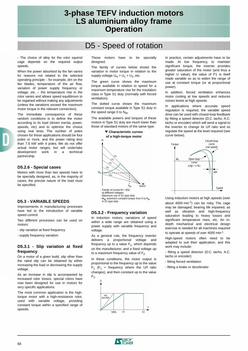
3-phase TEFV induction motorsLS aluminium alloy frame
Operation
68
- The choice of alloy for the rotor squirrelcage depends on the required outputspeeds.
When the power absorbed by the fan variesfor reasons not related to the selectedoperating principle – for example, dirt on thefan blades, temperature of the air flow,variation of power supply frequency orvoltage, etc. – the temperature rise in therotor varies and allows speed equilibrium tobe regained without making any adjustments(unless the variations exceed the maximummotor torque in the relevant connection).
The immediate consequence of theserandom conditions is to define the motoraccording to its load (driven inertia, power,speeds, etc) and to optimize the choiceusing real tests. The number of poleschosen for these applications should be fourpoles or more, and the power rating lessthan 7.5 kW with 4 poles. We do not offeractual motor ranges, but will undertakedevelopment work in a technicalpartnership.
D5.2.6 - Special casesMotors with more than two speeds have tobe specially designed, as, in the majority ofcases, the precise nature of the load mustbe specified.
D5.3 - VARIABLE SPEEDSImprovements in manufacturing processeshave led to the introduction of variablespeed control.
Two different processes can be used onmotors:
- slip variation at fixed frequency
- supply frequency variation
D5.3.1 - Slip variation at fixedfrequencyOn a motor of a given build, slip other thanthe rated slip can be obtained by eitherincreasing the load or decreasing the supplyvoltage.
As an increase in slip is accompanied byincreased rotor losses, special rotors havenow been designed for use in motors forvery specific applications.
The most common application is the high-torque motor with a high-resistance rotor,used with variable voltage, providingconstant torque within a specified range ofspeeds.
These motors have to be speciallydesigned.
The family of curves below shows thevariation in motor torque in relation to thesupply voltage UN > U1 > U2, etc.
The green curve shows the maximumtorque available in relation to speed for amaximum temperature rise for the insulationclass in Type S1 duty (normally with forcedventilation).
The dotted curve shows the maximumconstant torque available in Type S1 duty inthe speed range 0 to NM.
The available powers and torques of thesemotors in Type S1 duty are much lower thanthose of standard motors of the same type.
Characteristic curvesof a high-torque motor
D5.3.2 - Frequency variationIn induction motors, variations of speedwithin a wide range are obtained using apower supply with variable frequency andvoltage.
As a general rule, the frequency inverterdelivers a proportional voltage andfrequency up to a value F1, which dependson the manufacturer, and a fixed voltage upto a maximum frequency value of F2.
In these conditions, the motor output isproportional to the frequency up to the valueF1 (F1 = frequency where the U/f ratiochanges), and then constant up to the valueF2.
In practice, certain adjustments have to bemade. At low frequency, to maintainsignificant torque, the inverter providesgreater saturation of the motor (and thus ahigher U value); the value of F1 is itselfmade variable so as to widen the range ofuse at constant torque (or at proportionalpower).
In addition, forced ventilation enhancesmotor cooling at low speeds and reducesnoises levels at high speeds.
In applications where accurate speedregulation is required, the variable speeddrive can be used with closed-loop feedbackby fitting a speed detector (D.C. tacho, A.C.tacho or encoder) which will send a signal tothe inverter to change its U/f ratio and soregulate the speed at the level required (seecurve below).
Using induction motors at high speeds (over
about 4000 min-1) can be risky. The cagemay be damaged, bearing life impaired, aswell as vibration and high-frequencysaturation leading to heavy losses andsignificant temperature rises, etc. An in-depth mechanical and electrical designexercise is needed for all machines requiredto operate at speeds of over 4000 min-1.
High-speed motors often need to beadapted to suit their application, and thiswork may include:
- fitting a speed detector (D.C. tacho, A.C.tacho or encoder)
- fitting forced ventilation
- fitting a brake or decelerator
MM
Un
U1
U2
U3
UH
NM Speed
M
- Family of curves M = f(N) at different voltages- Maximum use in S1 type duty- MM maximum constant torque from 0 to NM in S1 type duty
U
f
notpossible
50Hz F1 F2
Mn
∆N
Torque
Speed
Open-loopcurve
(slip = x %)
Closed-loopcurve
(set speed)
D5 - Speed of rotation
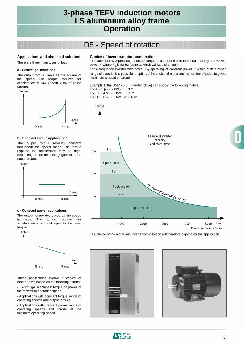
3-phase TEFV induction motorsLS aluminium alloy frame
Operation
69
Applications and choice of solutionsThere are three main types of load:
a - Centrifugal machines
The output torque varies as the square ofthe speed. The torque required foracceleration is low (about 20% of ratedtorque).
b - Constant torque applications
The output torque remains constantthroughout the speed range. The torquerequired for acceleration may be high,depending on the machine (higher than therated torque).
c - Constant power applications
The output torque decreases as the speedincreases. The torque required foracceleration is at most equal to the ratedtorque.
These applications involve a choice ofmotor-drives based on the following criteria:
- Centrifugal machines: torque or power atthe maximum operating speed.
- Applications with constant torque: range ofoperating speeds and output torques.
- Applications with constant power: range ofoperating speeds and torque at theminimum operating speed.
Torque
Speed
N min. N max.
Torque
Speed
N min. N max.
Torque
Speed
N min. N max.
D5 - Speed of rotationChoice of inverter/motor combinationThe curve below expresses the output torque of a 2, 4 or 6 pole motor supplied by a drive withpower P where F1 is 50 Hz (point at which U/f ratio changes).For a frequency inverter with power PN operating at constant power P within a determinedrange of speeds, it is possible to optimize the choice of motor and its number of poles to give amaximum amount of torque.
Example 1: the UMV - 3.5 T inverter (drive) can supply the following motors:LS 90 - 2 p - 2.2 kW - 7.5 N.mLS 100 - 4 p - 2.2 kW - 15 N.mLS 112 - 6 p - 2.2 kW - 22.5 N.m
The choice of the motor and inverter combination will therefore depend on the application.
3M6 p
4 p
2 p
1000 2000 3000 4000 5000
2M
M
Torque
2 pole motor
N min-1
Change of invertercapacity
and motor type
Values for base of 50 Hz
Operation at constant power (P)
4 pole motor
6 pole motor
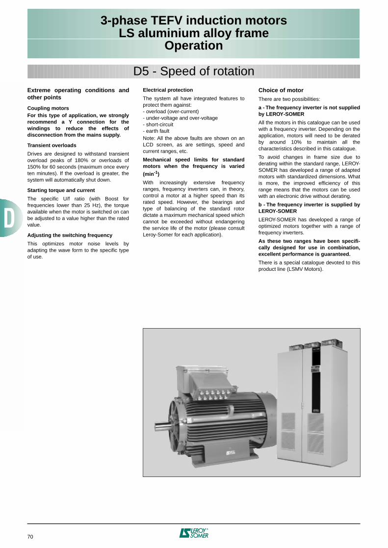
3-phase TEFV induction motorsLS aluminium alloy frame
Operation
70
Extreme operating conditions andother points
Coupling motorsFor this type of application, we stronglyrecommend a Y connection for thewindings to reduce the effects ofdisconnection from the mains supply.
Transient overloads
Drives are designed to withstand transientoverload peaks of 180% or overloads of150% for 60 seconds (maximum once everyten minutes). If the overload is greater, thesystem will automatically shut down.
Starting torque and current
The specific U/f ratio (with Boost forfrequencies lower than 25 Hz), the torqueavailable when the motor is switched on canbe adjusted to a value higher than the ratedvalue.
Adjusting the switching frequency
This optimizes motor noise levels byadapting the wave form to the specific typeof use.
Electrical protection
The system all have integrated features toprotect them against:- overload (over-current)- under-voltage and over-voltage- short-circuit- earth faultNote: All the above faults are shown on anLCD screen, as are settings, speed andcurrent ranges, etc.
Mechanical speed limits for standardmotors when the frequency is varied
(min-1)
With increasingly extensive frequencyranges, frequency inverters can, in theory,control a motor at a higher speed than itsrated speed. However, the bearings andtype of balancing of the standard rotordictate a maximum mechanical speed whichcannot be exceeded without endangeringthe service life of the motor (please consultLeroy-Somer for each application).
Choice of motorThere are two possibilities:
a - The frequency inverter is not suppliedby LEROY-SOMER
All the motors in this catalogue can be usedwith a frequency inverter. Depending on theapplication, motors will need to be deratedby around 10% to maintain all thecharacteristics described in this catalogue.
To avoid changes in frame size due toderating within the standard range, LEROY-SOMER has developed a range of adaptedmotors with standardized dimensions. Whatis more, the improved efficiency of thisrange means that the motors can be usedwith an electronic drive without derating.
b - The frequency inverter is supplied byLEROY-SOMER
LEROY-SOMER has developed a range ofoptimized motors together with a range offrequency inverters.
As these two ranges have been specifi-cally designed for use in combination,excellent performance is guaranteed.
There is a special catalogue devoted to thisproduct line (LSMV Motors).
D5 - Speed of rotation
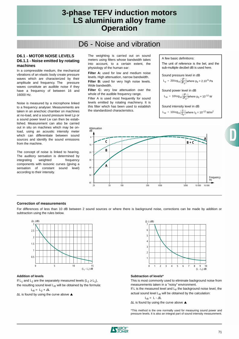
3-phase TEFV induction motorsLS aluminium alloy frame
Operation
71
D6.1 - MOTOR NOISE LEVELSD6.1.1 - Noise emitted by rotatingmachinesIn a compressible medium, the mechanicalvibrations of an elastic body create pressurewaves which are characterized by theiramplitude and frequency. The pressurewaves constitute an audible noise if theyhave a frequency of between 16 and16000 Hz.
Noise is measured by a microphone linkedto a frequency analyser. Measurements aretaken in an anechoic chamber on machinesat no-load, and a sound pressure level Lp ora sound power level Lw can then be estab-lished. Measurement can also be carriedout in situ on machines which may be on-load, using an acoustic intensity meterwhich can differentiate between soundsources and identify the sound emissionsfrom the machine.
The concept of noise is linked to hearing.The auditory sensation is determined byintegrating weighted frequencycomponents with isosonic curves (giving asensation of constant sound level)according to their intensity.
D6 - Noise and vibrationThe weighting is carried out on soundmeters using filters whose bandwidth takesinto account, to a certain extent, thephysiology of the human ear:
Filter A: used for low and medium noiselevels. High attenuation, narrow bandwidth.Filter B: used for very high noise levels.Wide bandwidth.Filter C: very low attenuation over thewhole of the audible frequency range.Filter A is used most frequently for soundlevels emitted by rotating machinery. It isthis filter which has been used to establishthe standardized characteristics.
A few basic definitions:
The unit of reference is the bel, and thesub-multiple decibel dB is used here.
Sound pressure level in dB
Sound power level in dB
Sound intensity level in dB
Lp 20log10PP0------
= where p0 = 2.10-5 Pa
LW 10log10PP0------
= where p0 = 10-12 W
LW 10log10II0----
= where I0 = 10-12 W/m2
FrequencyHz
0
50
C
20
10
20
30
40
50
60100 500 1000 5000 10 000 16 000
B
A
B + CA
AttenuationdB
Correction of measurementsFor differences of less than 10 dB between 2 sound sources or where there is background noise, corrections can be made by addition orsubtraction using the rules below.
Addition of levelsIf L1 and L2 are the separately measured levels (L2 ≥ L1),the resulting sound level LR will be obtained by the formula:
LR = L2 + ∆L∆L is found by using the curve above
Subtraction of levels*This is most commonly used to eliminate background noise frommeasurements taken in a "noisy” environment.If L is the measured level and LF the background noise level, theactual sound level LR will be obtained by the calculation:
LR = L - ∆L∆L is found by using the curve above
*This method is the one normally used for measuring sound power andpressure levels. It is also an integral part of sound intensity measurement.
0.5
0
1
1.5
2
2.5
3 L (dB)
(L2 - L1) dB155 10 0
7 L (dB)
(L - LF) dB1 2 3 4 5 6 7 8 9 10
1
2
3
4
5
6
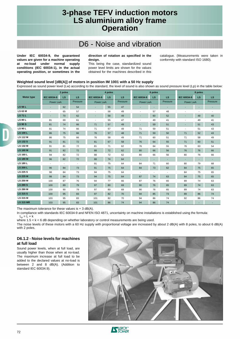
3-phase TEFV induction motorsLS aluminium alloy frame
Operation
72
D6 - Noise and vibrationUnder IEC 60034-9, the guaranteedvalues are given for a machine operatingat no-load under normal supplyconditions (IEC 60034-1), in the actualoperating position, or sometimes in the
direction of rotation as specified in thedesign.This being the case, standardized soundpower level limits are shown for the valuesobtained for the machines described in this
catalogue. (Measurements were taken inconformity with standard ISO 1680).
Weighted sound level [dB(A)] of motors in position IM 1001 with a 50 Hz supplyExpressed as sound power level (Lw) according to the standard, the level of sound is also shown as sound pressure level (Lp) in the table below:
The maximum tolerance for these values is + 3 dB(A).In compliance with standards IEC 60034-9 and NFEN ISO 4871, uncertainty on machine installations is established using the formula: Lp = L + kwhere 1.5 < k < 6 dB depending on whether laboratory or control measurements are being used.The noise levels of these motors with a 60 Hz supply with proportional voltage are increased by about 2 dB(A) with 8 poles, to about 6 dB(A)with 2 poles.
Motor type
2 poles 4 poles 6 poles 8 poles
IEC 60034-9 LS LS IEC 60034-9 LS LS IEC 60034-9 LS LS IEC 60034-9 LS LS
Power LwA Pressure Power LwA Pressure Power LwA Pressure Power LwA Pressure
LS 56 L - 62 54 - 55 47 - - - - - -
LS 63 M - 65 57 - 58 49 - 57 48 - - -
LS 71 L - 70 62 - 58 49 - 60 52 - 48 40
LS 80 L 81 69 61 - 55 47 - 49 41 - 49 41
LS 90 S 81 74 66 71 57 49 - 59 51 - 51 43
LS 90 L 81 74 66 71 57 49 71 59 51 - 51 43
LS 100 L 86 75 66 76 57 48 71 59 50 71 52 43
LS 112 M 86 75 66 76 58 49 71 60 51 71 58 49
LS 132 S 91 81 72 81 67 58 76 64 55 71 60 51
LS 132 M 91 81 72 81 71 62 76 64 55 76 63 54
LS 160 M 91 82 72 88 72 62 80 66 56 76 76 66
LS 160 L 94 82 72 88 72 62 80 66 56 80 76 66
LS 180 M 96 82 72 88 74 64 - - - - - -
LS 180 L - - - 91 75 64 84 71 60 80 79 68
LS 200 L 96 84 73 91 75 64 84 73 62 84 75 65
LS 225 S 98 84 73 94 75 64 - - - 84 75 65
LS 225 M 98 84 73 94 75 64 87 74 63 84 75 65
LS 250 M 100 87 76 94 77 66 87 76 65 89 74 63
LS 280 S 100 89 79 97 80 69 90 76 65 89 74 63
LS 280 M 100 90 79 97 80 69 90 76 65 89 74 63
LS 315 S 100 95 83 97 82 70 94 85 73 89 86 74
LS 315 M 103 95 83 101 82 70 94 86 74 92 86 74
LS 315 MR 103 95 83 101 86 74 94 86 74 - - -
D6.1.2 - Noise levels for machinesat full loadSound power levels, when at full load, areusually higher than those when at no-load.The maximum increase at full load to beadded to the declared values at no-load isbetween 2 and 8 dB(A). (Addition tostandard IEC 60034.9).
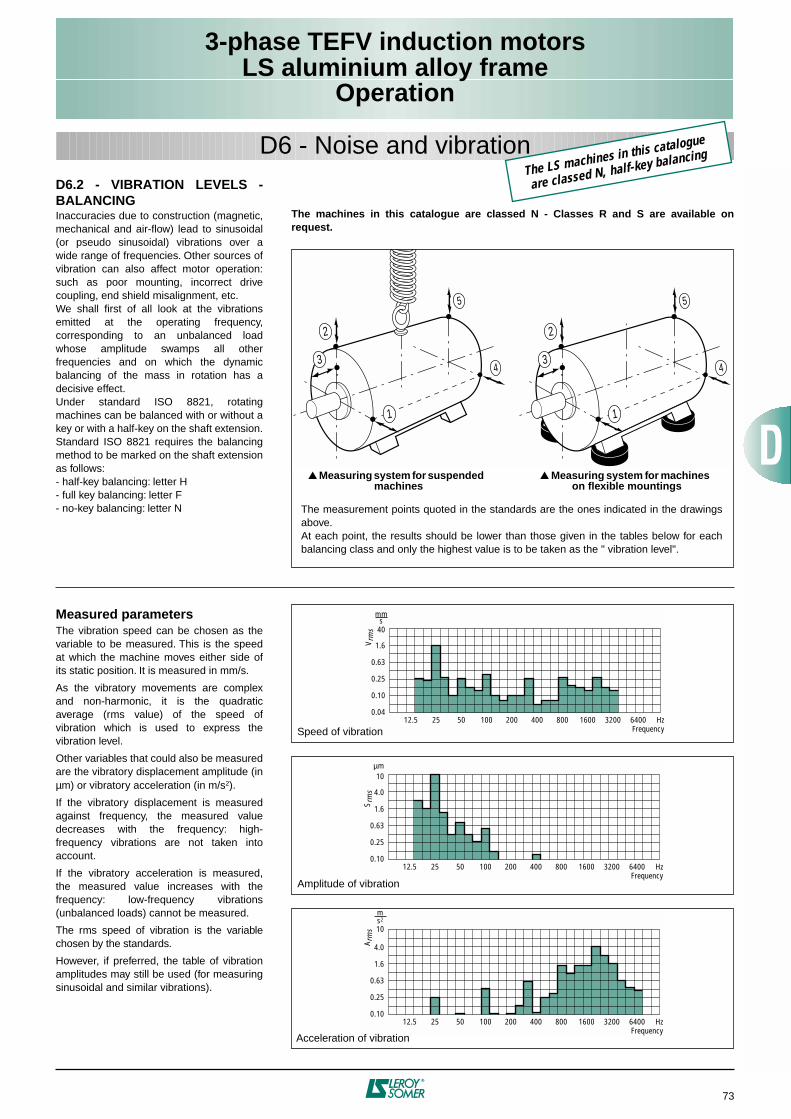
3-phase TEFV induction motorsLS aluminium alloy frame
Operation
73
D6 - Noise and vibrationD6.2 - VIBRATION LEVELS -BALANCINGInaccuracies due to construction (magnetic,mechanical and air-flow) lead to sinusoidal(or pseudo sinusoidal) vibrations over awide range of frequencies. Other sources ofvibration can also affect motor operation:such as poor mounting, incorrect drivecoupling, end shield misalignment, etc.We shall first of all look at the vibrationsemitted at the operating frequency,corresponding to an unbalanced loadwhose amplitude swamps all otherfrequencies and on which the dynamicbalancing of the mass in rotation has adecisive effect.Under standard ISO 8821, rotatingmachines can be balanced with or without akey or with a half-key on the shaft extension.Standard ISO 8821 requires the balancingmethod to be marked on the shaft extensionas follows:- half-key balancing: letter H- full key balancing: letter F- no-key balancing: letter N
Measured parametersThe vibration speed can be chosen as thevariable to be measured. This is the speedat which the machine moves either side ofits static position. It is measured in mm/s.
As the vibratory movements are complexand non-harmonic, it is the quadraticaverage (rms value) of the speed ofvibration which is used to express thevibration level.
Other variables that could also be measuredare the vibratory displacement amplitude (inµm) or vibratory acceleration (in m/s2).
If the vibratory displacement is measuredagainst frequency, the measured valuedecreases with the frequency: high-frequency vibrations are not taken intoaccount.
If the vibratory acceleration is measured,the measured value increases with thefrequency: low-frequency vibrations(unbalanced loads) cannot be measured.
The rms speed of vibration is the variablechosen by the standards.
However, if preferred, the table of vibrationamplitudes may still be used (for measuringsinusoidal and similar vibrations).
The machines in this catalogue are classed N - Classes R and S are available onrequest.
1
4
5
2
3
1
4
5
2
3
Measuring system for suspended machines
Measuring system for machines on flexible mountings
The measurement points quoted in the standards are the ones indicated in the drawingsabove.At each point, the results should be lower than those given in the tables below for eachbalancing class and only the highest value is to be taken as the " vibration level".
0.04
0.10
0.25
0.63
1.6
40
mms
12.5 25 50 100 200 400 800 1600 3200 6400 HzFrequency
V rm
s
Speed of vibration
0.10
0.25
0.63
1.6
4.0
10µm
12.5 25 50 100 200 400 800 1600 3200 6400 HzFrequency
S rm
s
Amplitude of vibration
0.10
0.25
0.63
1.6
4.0
10
12.5 25 50 100 200 400 800 1600 3200 6400 HzFrequency
ms2
A rm
s
Acceleration of vibration
The LS machines in this catalogue
are classed N, half-key balancing
3-phase TEFV induction motorsLS aluminium alloy frame
Operation
74
D6 - Noise and vibrationMaximum value of rms speed of vibration expressed in mm/s (IEC 60034-14)
(machine tested when freely suspended)
Maximum value of the simple displacement amplitude expressed in µm (for sinusoidal vibrations only)
ClassSpeed
N (min-1)
Frame size H (mm)
H ≤ 132 132 < H ≤ 225 225 < H ≤ 315
N (normal) 600 < N ≤ 3600 1.8 2.8 3.5
R (reduced) 600 < N ≤ 18001800 < N ≤ 3600
0.711.12
1.121.8
1.82.8
S (special) 600 < N ≤ 18001800 < N ≤ 3600
0.450.71
0.711.12
1.121.8
ClassSpeed
N (min-1)
Frame size H (mm)
H ≤ 132 132 < H ≤ 225 225 < H ≤ 315
N (normal)100015003000
24168
3825
12.5
483216
R (reduced)100015003000
96.35
16108
2416
12.5
S (special)100015003000
6.34
3.15
96.35
16108
3-phase TEFV induction motorsLS aluminium alloy frame
Operation
75
D7 - PerformanceD7.1 - THERMAL PROTECTIONMotors are protected by a manual orautomatic overcurrent relay, placed betweenthe isolating switch and the motor. This relaymay in turn be protected by fuses.These protection devices provide totalprotection of the motor against non-transient
overloads. If a shorter reaction time isrequired, or if you want to detect transientoverloads, or to monitor temperature rises at"hot spots" in the motor or at strategic pointsin the installation for maintenance purposes,it would be advisable to install heat sensors.The various types are shown in the table
below, with a description of each. It must beemphasized that sensors cannot be used tocarry out direct adjustments to the motoroperating cycles.
Built-in indirect thermal protection
- NRT: nominal running temperature- The NRTs are chosen according to the position of the sensor in the motor and the temperature rise class.* The number of devices relates to the winding protection.
Fitting thermal protection- PTO or PTF, in the control circuits- PTC, with relay, in the control circuits- PT 100 or Thermocouples, with readingequipment or recorder, in the control board ofthe installation for continuous surveillance.
Alarm and early warningAll protective equipment may be backed upby another type of protection (with differentNRTs). The first device will then act as an"early warning" (light or sound signals givenwithout shutting down the power circuits),and the second device will be the actualalarm (shutting down the power circuits).
Built-in direct thermal protectionFor low rated currents, bimetallic strip-typeprotection may be used. The line currentpasses through the strip, which shuts down orrestores the supply circuit as necessary. Thedesign of this type of protection allows formanual or automatic reset.
Type Symbol Operatingprinciple
Operatingcurve
Cut-off(A) Protection provided Mounting
Number of devices*
Normally closedthermostat
PTO
bimetallic strip, indirectly heated, with normally closed (NC) contact 2.5 A at 250 V
with cos ϕ 0.4general surveillance
for non-transient overloads2 or 3 in series
Normally openthermostat
PTF
bimetallic strip, indirectly heated, with normally
open (NO) contact 2.5 A at 250 Vwith cos ϕ 0.4
general surveillancefor non-transient overloads
2 or 3 in parallel
Positive temperature coefficient thermistor
PTC
Variable non-linear resistor with indirect
heating0
general surveillancefor transient overloads
3 in series
Thermocouples
T (T < 150 °C)Copper Constantan
K (T < 1000 °C)Copper
Copper-Nickel
Peltier effect 0continuous surveillance
at hot spots1 per hot spot
Platinum resistance thermometer
PT 100Variable linear resistor with indirect heating
0high accuracy continuous
surveillance at key hot spots1 per hot spot
I
O TNF
T
I
F TNF
T
R
TNF
T
V
T
R
T
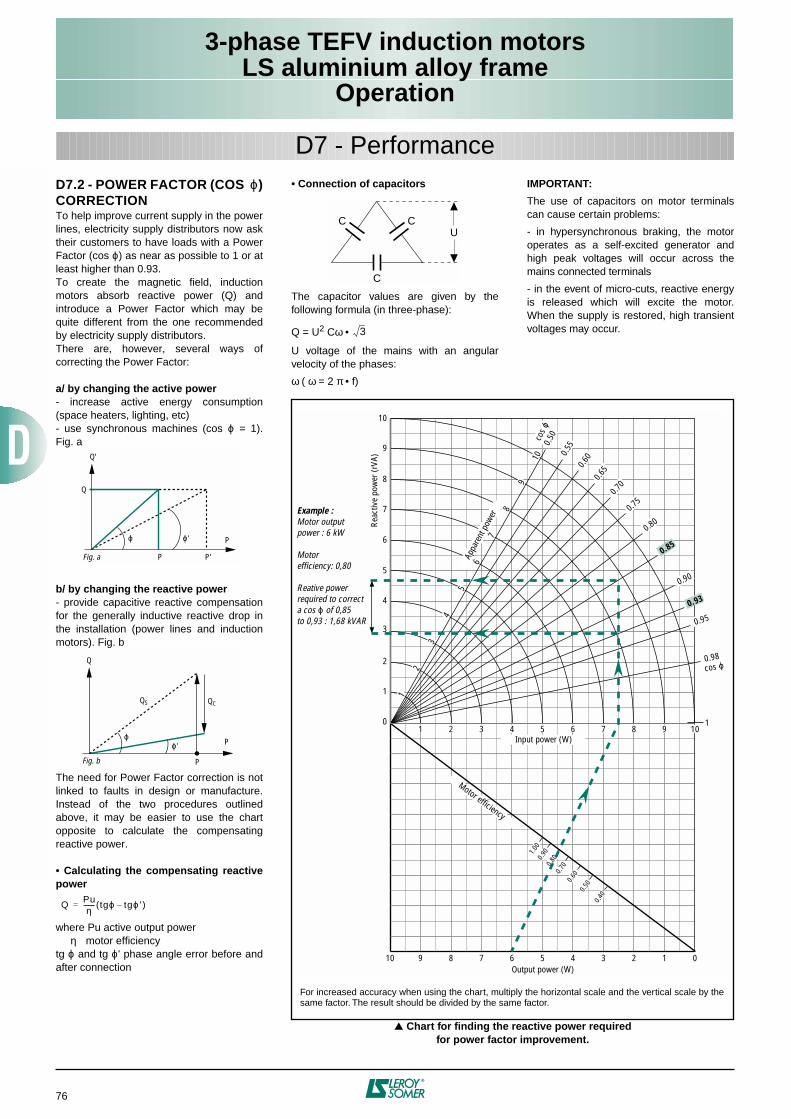
3-phase TEFV induction motorsLS aluminium alloy frame
Operation
76
D7.2 - POWER FACTOR (COS ϕ)CORRECTIONTo help improve current supply in the powerlines, electricity supply distributors now asktheir customers to have loads with a PowerFactor (cos ϕ) as near as possible to 1 or atleast higher than 0.93.To create the magnetic field, inductionmotors absorb reactive power (Q) andintroduce a Power Factor which may bequite different from the one recommendedby electricity supply distributors.There are, however, several ways ofcorrecting the Power Factor:
a/ by changing the active power- increase active energy consumption(space heaters, lighting, etc)- use synchronous machines (cos ϕ = 1).Fig. a
b/ by changing the reactive power- provide capacitive reactive compensationfor the generally inductive reactive drop inthe installation (power lines and inductionmotors). Fig. b
The need for Power Factor correction is notlinked to faults in design or manufacture.Instead of the two procedures outlinedabove, it may be easier to use the chartopposite to calculate the compensatingreactive power.
• Calculating the compensating reactivepower
where Pu active output power η motor efficiencytg ϕ and tg ϕ' phase angle error before andafter connection
Q
ϕ ϕ '
Q'
P
PFig. a P'
P
ϕϕ'
Q
P
QS QC
Fig. b
QPuη
------- tgϕ tgϕ′–( )=
D7 - Performance• Connection of capacitors
The capacitor values are given by thefollowing formula (in three-phase):
Q = U2 Cω •
U voltage of the mains with an angularvelocity of the phases:
ω ( ω = 2 π • f)
IMPORTANT:
The use of capacitors on motor terminalscan cause certain problems:
- in hypersynchronous braking, the motoroperates as a self-excited generator andhigh peak voltages will occur across themains connected terminals
- in the event of micro-cuts, reactive energyis released which will excite the motor.When the supply is restored, high transientvoltages may occur.
C C
C
U
3
Chart for finding the reactive power requiredfor power factor improvement.
0
1
2
3
4
5
6
7
8
9
10
1
0.98
0.95
0.93
0.90
0.85
0.800.7
5
0.70
0.650.6
00.550.
50
10 9 8 7 6 5 4 3 2 1 0
1 2 3 4 5 6 7 8 9 10
1
2
3
4
5
6
7
8
9
101.0
00.9
00.8
00.7
00.6
00.5
00.4
0
cos ϕ
cos ϕ
Example :Motor outputpower : 6 kW
Motorefficiency: 0,80
Reative powerrequired to correcta cos ϕ of 0,85to 0,93 : 1,68 kVAR
Output power (W)
Motor efficiency
Input power (W)
Reac
tive
pow
er (r
VA)
Appa
rent
pow
er
For increased accuracy when using the chart, multiply the horizontal scale and the vertical scale by thesame factor. The result should be divided by the same factor.
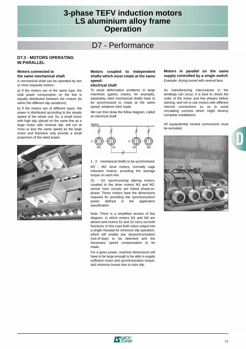
3-phase TEFV induction motorsLS aluminium alloy frame
Operation
77
D7.3 - MOTORS OPERATINGIN PARALLEL
Motors connected tothe same mechanical shaftA mechanical shaft can be operated by twoor more separate motors:
a) If the motors are of the same type, thetotal power consumption on the line isequally distributed between the motors (towithin the different slip variations).
b) If the motors are of different types, thepower is distributed according to the steadyspeed of the whole unit. So, a small motorwith high slip, placed on the same line as alarge motor with minimal slip, will run atmore or less the same speed as the largemotor and therefore only provide a smallproportion of the rated power.
Motors coupled to independentshafts which must rotate at the samespeed:electrical shaftTo avoid deformation problems in largemachines (gantry cranes, for example),separately sited mechanical shafts have tobe synchronized to rotate at the samespeed, whatever their loads.
We can then draw the follow diagram, calledan electrical shaft:
1 - 2 : mechanical shafts to be synchronized
M1 - M2: drive motors, normally cageinduction motors, providing the averagetorque on each line.
S1 - S2: synchronizing slipring motors,coupled to the drive motors M1 and M2,whose rotor circuits are linked phase-to-phase. These motors have the dimensionsrequired for providing the synchronizationpower defined in the applicationspecification.
Note: There is a simplified version of thisdiagram, in which motors M1 and M2 areabsent and motors S1 and S2 carry out bothfunctions. In this case both rotors output intoa single rheostat for minimum slip operation,which will enable any desynchronization(out-of-step) to be detected and thenecessary speed compensation to bemade.
For a given power, machine dimensions willhave to be large enough to be able to supplysufficient motor and synchronization torque,and minimize losses due to rotor slip.
Motors in parallel on the samesupply controlled by a single switchExample: drying tunnel with several fans.
As manufacturing inaccuracies in thewindings can occur, it is best to check theorder of the motor and line phases beforestarting, and not to use motors with differentinternal connections so as to avoidcirculating currents which might destroycomplete installations.
All equipotential neutral connections mustbe excluded.
1
M1 S1
2
S2 M2
Mains
D7 - Performance
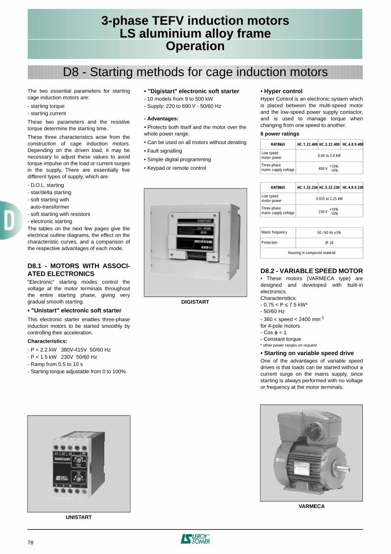
3-phase TEFV induction motorsLS aluminium alloy frame
Operation
78
The two essential parameters for startingcage induction motors are:
- starting torque- starting current
These two parameters and the resistivetorque determine the starting time.
These three characteristics arise from theconstruction of cage induction motors.Depending on the driven load, it may benecessary to adjust these values to avoidtorque impulse on the load or current surgesin the supply. There are essentially fivedifferent types of supply, which are:
- D.O.L. starting- star/delta starting- soft starting with auto-transformer- soft starting with resistors- electronic startingThe tables on the next few pages give theelectrical outline diagrams, the effect on thecharacteristic curves, and a comparison ofthe respective advantages of each mode.
D8.1 - MOTORS WITH ASSOCI-ATED ELECTRONICS"Electronic" starting modes control thevoltage at the motor terminals throughoutthe entire starting phase, giving verygradual smooth starting.
• "Unistart" electronic soft starterThis electronic starter enables three-phaseinduction motors to be started smoothly bycontrolling their acceleration.
Characteristics:
- P < 2.2 kW 380V-415V 50/60 Hz- P < 1.5 kW 230V 50/60 Hz- Ramp from 0.5 to 10 s- Starting torque adjustable from 0 to 100%.
UNISTART
• "Digistart" electronic soft starter- 10 models from 9 to 500 kW- Supply: 220 to 690 V - 50/60 Hz
- Advantages:
• Protects both itself and the motor over thewhole power range.
• Can be used on all motors without derating
• Fault signalling
• Simple digital programming
• Keypad or remote control
DIGISTART
• Hyper controlHyper Control is an electronic system whichis placed between the multi-speed motorand the low-speed power supply contactor,and is used to manage torque whenchanging from one speed to another.
6 power ratings
D8.2 - VARIABLE SPEED MOTOR• These motors (VARMECA type) aredesigned and developed with built-inelectronics.Characteristics:- 0.75 < P ≤ 7.5 kW*- 50/60 Hz
- 360 < speed < 2400 min-1
for 4-pole motors- Cos ϕ = 1- Constant torque* other power ranges on request
• Starting on variable speed driveOne of the advantages of variable speeddrives is that loads can be started without acurrent surge on the mains supply, sincestarting is always performed with no voltageor frequency at the motor terminals.
VARMECA
RATINGS HC.1.22.400 HC.3.22.400 HC.4.8.9.400
Low speed motor power 0.06 to 3.9 kW
Three-phase mains supply voltage 400 V
RATINGS HC.1.22.230 HC.3.22.230 HC.4.8.9.230
Low speed motor power 0.035 to 2.25 kW
Three-phase mains supply voltage 230 V
Mains frequency 50 / 60 Hz ±5%
Protection IP 20
Housing in composite material
+10%-10%
+10%-10%
D8 - Starting methods for cage induction motors
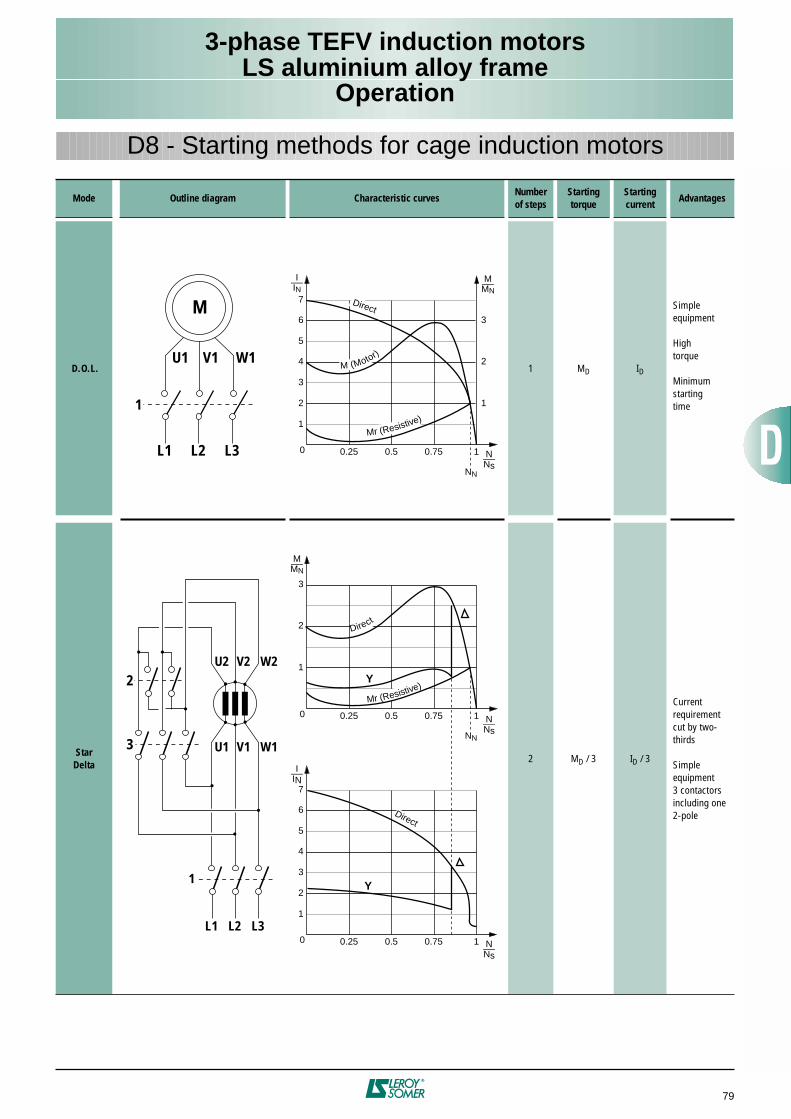
3-phase TEFV induction motorsLS aluminium alloy frame
Operation
79
Mode Outline diagram Characteristic curvesNumberof steps
Starting torque
Starting current
Advantages
D.O.L. 1 MD ID
Simpleequipment
Hightorque
Minimumstartingtime
StarDelta
2 MD / 3 ID / 3
Currentrequirementcut by two-thirds
Simpleequipment3 contactorsincluding one2-pole
D8 - Starting methods for cage induction motors
L3L2L1
W1V1U1
M
1
L3L2L1
W1V1U1
1
3
W2V2U2
M_MN
N_Ns
0.25 0.5 0.75 1
1
2
3
I_IN
2
4
6
1
3
5
7
0
M (Motor)
Direct
Mr (Resistive)
M_MN
N_Ns
0.25 0.5 0.75 1
1
2
3
0
Direct
Mr (Resistive)Y
N_Ns
0.25 0.5 0.75 1
I_IN
2
4
6
1
3
5
7
0
Y
Direct
NN
2
NN
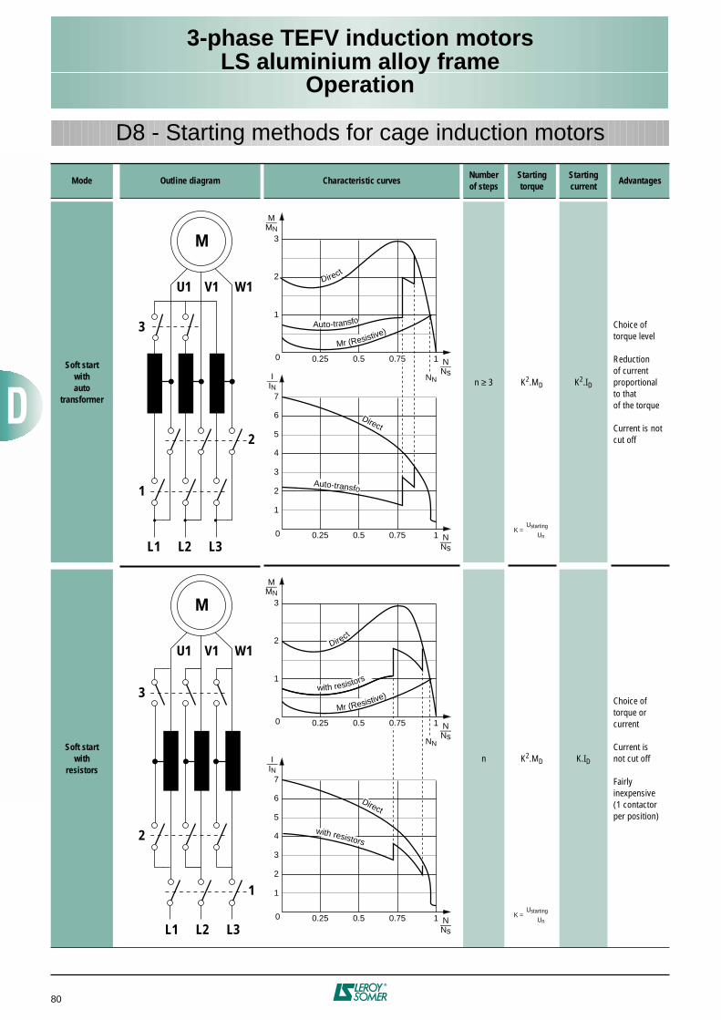
3-phase TEFV induction motorsLS aluminium alloy frame
Operation
80
D8 - Starting methods for cage induction motors
Mode Outline diagram Characteristic curvesNumberof steps
Starting torque
Starting current
Advantages
Soft startwithauto
transformer
n ≥ 3 K2.MD K2.ID
Choice oftorque level
Reductionof currentproportionalto thatof the torque
Current is notcut off
Soft startwith
resistorsn K2.MD K.ID
Choice oftorque orcurrent
Current isnot cut off
Fairly inexpensive(1 contactorper position)
W1V1U1
M
2
L3L2L1
1
3
W1V1U1
1
L3L2L1
2
3
M
M_MN
N_Ns
0.25 0.5 1
1
2
3
0
Direct
Mr (Resistive)
N_Ns
0.25 0.5 0.75 1
I_IN
2
4
6
1
3
5
7
0
Auto-transfo
Auto-transfo
Direct
M_MN
N_Ns
0.25 0.5 1
1
2
3
0
Mr (Resistive)
N_Ns
0.25 0.5 0.75 1
I_IN
2
4
6
1
3
5
7
0
Direct
with resistors
Direct
with resistors
0.75
0.75
NN
NN
K =Ustarting
Un
K =Ustarting
Un
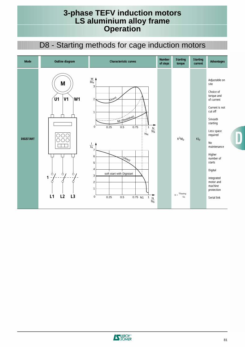
3-phase TEFV induction motorsLS aluminium alloy frame
Operation
81
D8 - Starting methods for cage induction motors
Mode Outline diagram Characteristic curvesNumberof steps
Starting torque
Starting current
Advantages
DIGISTART K2MD KID
Adjustable onsite
Choice oftorque andof current
Current is notcut off
Smooth starting
Less spacerequired
No maintenance
Highernumber ofstarts
Digital
integratedmotor and machineprotection
Serial link
W1V1U1
MM_
MN
N_Ns
0.25 0.5 1
1
2
3
0
Direct
N_Ns
0.25 0.5 0.75 1
I_IN
2
4
6
1
3
5
7
0 N1
Direct
Mr (Resistive)
soft start with Digistart
0.75
L3L2L1
1
NN
K =Ustarting
Un
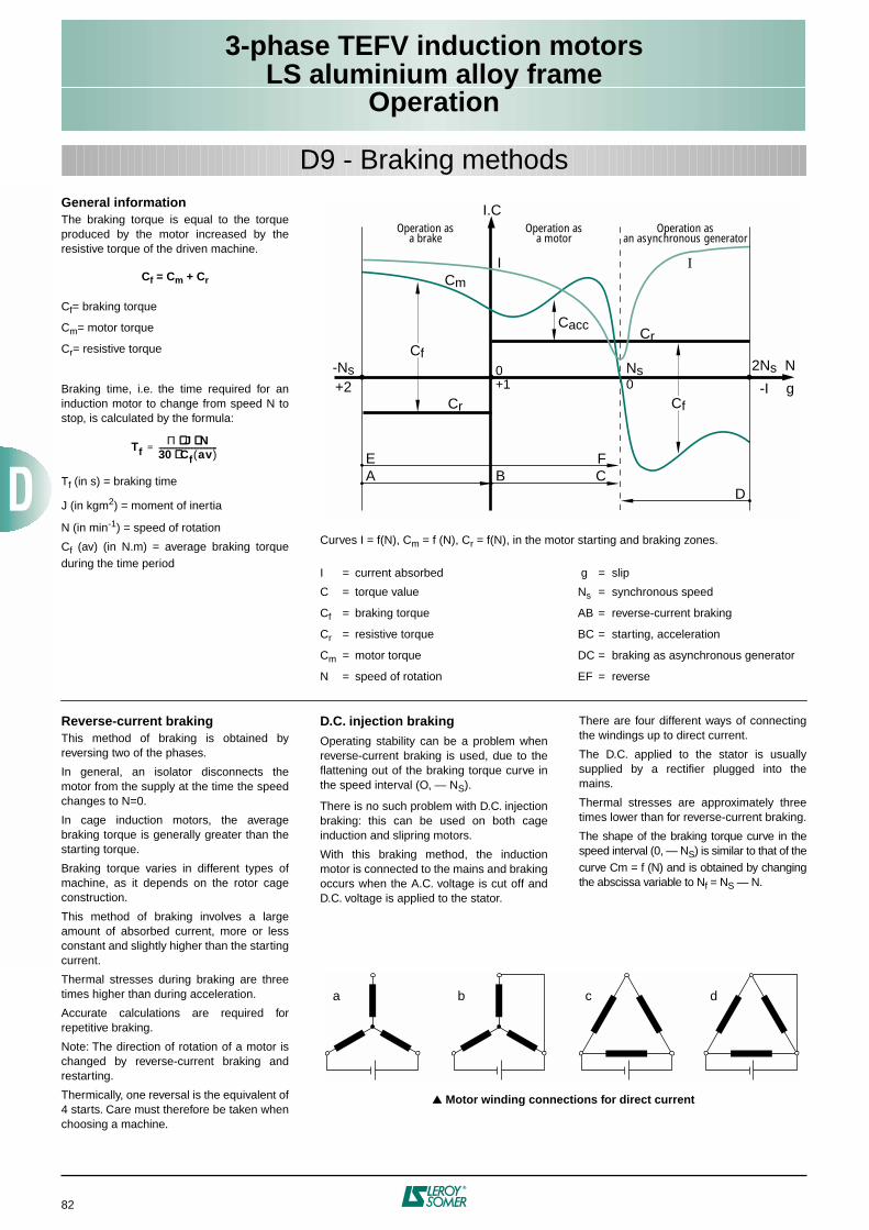
3-phase TEFV induction motorsLS aluminium alloy frame
Operation
82
General informationThe braking torque is equal to the torqueproduced by the motor increased by theresistive torque of the driven machine.
Cf = Cm + Cr
Cf= braking torque
Cm= motor torque
Cr= resistive torque
Braking time, i.e. the time required for aninduction motor to change from speed N tostop, is calculated by the formula:
Tf (in s) = braking time
J (in kgm2) = moment of inertia
N (in min-1) = speed of rotation
Cf (av) (in N.m) = average braking torqueduring the time period
TfΠ J N⋅⋅⋅⋅ ⋅⋅⋅⋅
30 Cf av( )⋅⋅⋅⋅----------------------------------=
D9 - Braking methods
Curves I = f(N), Cm = f (N), Cr = f(N), in the motor starting and braking zones.
I = current absorbed g = slip
C = torque value Ns = synchronous speed
Cf = braking torque AB = reverse-current braking
Cr = resistive torque BC = starting, acceleration
Cm = motor torque DC = braking as asynchronous generator
N = speed of rotation EF = reverse
-Ns+2
2Ns
-I
N
g
I.C
Cm
Cr
Cf
EA B C
F
D
Cr
0+1
Ns0
Cf
I
Operation asa brake
Operation asa motor
Operation asan asynchronous generator
Cacc
I
Reverse-current brakingThis method of braking is obtained byreversing two of the phases.
In general, an isolator disconnects themotor from the supply at the time the speedchanges to N=0.
In cage induction motors, the averagebraking torque is generally greater than thestarting torque.
Braking torque varies in different types ofmachine, as it depends on the rotor cageconstruction.
This method of braking involves a largeamount of absorbed current, more or lessconstant and slightly higher than the startingcurrent.
Thermal stresses during braking are threetimes higher than during acceleration.
Accurate calculations are required forrepetitive braking.
Note: The direction of rotation of a motor ischanged by reverse-current braking andrestarting.
Thermically, one reversal is the equivalent of4 starts. Care must therefore be taken whenchoosing a machine.
D.C. injection brakingOperating stability can be a problem whenreverse-current braking is used, due to theflattening out of the braking torque curve inthe speed interval (O, — NS).
There is no such problem with D.C. injectionbraking: this can be used on both cageinduction and slipring motors.
With this braking method, the inductionmotor is connected to the mains and brakingoccurs when the A.C. voltage is cut off andD.C. voltage is applied to the stator.
There are four different ways of connectingthe windings up to direct current.
The D.C. applied to the stator is usuallysupplied by a rectifier plugged into themains.
Thermal stresses are approximately threetimes lower than for reverse-current braking.
The shape of the braking torque curve in thespeed interval (0, — NS) is similar to that of thecurve Cm = f (N) and is obtained by changingthe abscissa variable to Nf = NS — N.
Motor winding connections for direct current
a b c d
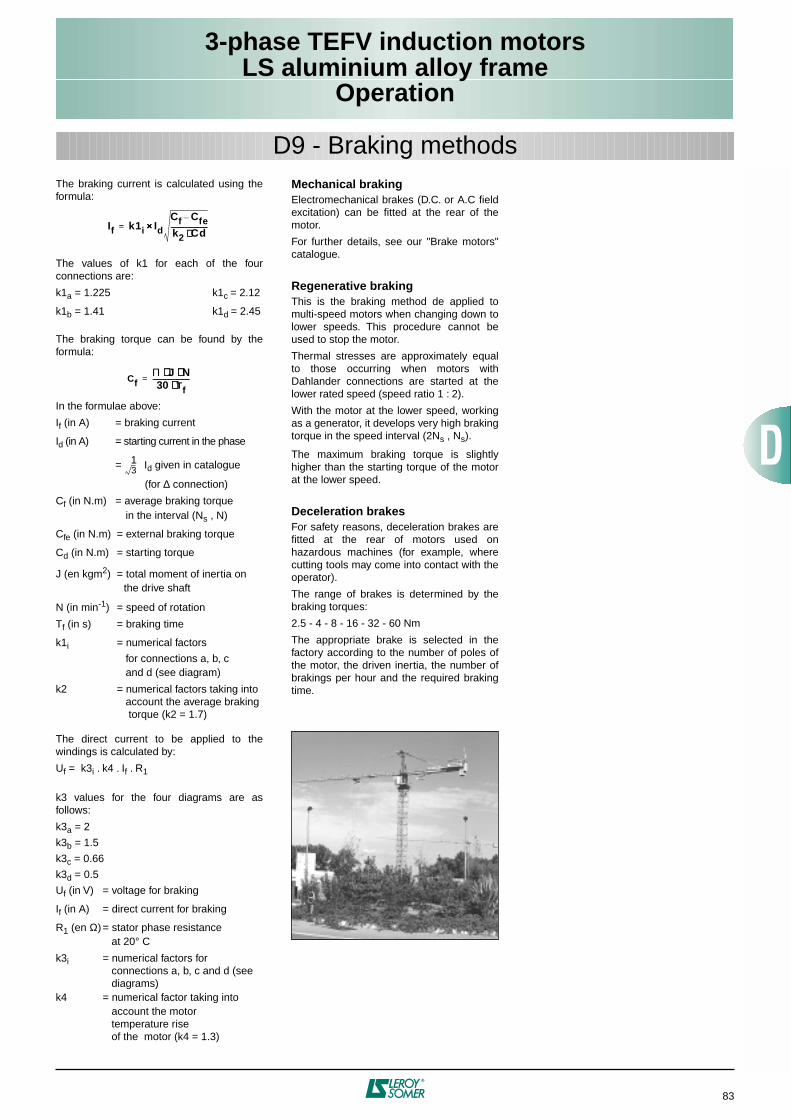
3-phase TEFV induction motorsLS aluminium alloy frame
Operation
83
The braking current is calculated using theformula:
The values of k1 for each of the fourconnections are:
k1a = 1.225 k1c = 2.12
k1b = 1.41 k1d = 2.45
The braking torque can be found by theformula:
In the formulae above:
If (in A) = braking current
Id (in A) = starting current in the phase
= Id given in catalogue
(for ∆ connection)
Cf (in N.m) = average braking torque in the interval (Ns , N)
Cfe (in N.m) = external braking torque
Cd (in N.m) = starting torque
J (en kgm2) = total moment of inertia on the drive shaft
N (in min-1) = speed of rotation
Tf (in s) = braking time
k1i = numerical factors
for connections a, b, c and d (see diagram)
k2 = numerical factors taking into account the average braking torque (k2 = 1.7)
The direct current to be applied to thewindings is calculated by:
Uf = k3i . k4 . If . R1
k3 values for the four diagrams are asfollows:
k3a = 2
k3b = 1.5
k3c = 0.66
k3d = 0.5
Uf (in V) = voltage for braking
If (in A) = direct current for braking
R1 (en Ω) = stator phase resistance at 20° C
k3i = numerical factors for connections a, b, c and d (see diagrams)
k4 = numerical factor taking into account the motor temperature rise of the motor (k4 = 1.3)
Mechanical brakingElectromechanical brakes (D.C. or A.C fieldexcitation) can be fitted at the rear of themotor.
For further details, see our "Brake motors"catalogue.
Regenerative brakingThis is the braking method de applied tomulti-speed motors when changing down tolower speeds. This procedure cannot beused to stop the motor.
Thermal stresses are approximately equalto those occurring when motors withDahlander connections are started at thelower rated speed (speed ratio 1 : 2).
With the motor at the lower speed, workingas a generator, it develops very high brakingtorque in the speed interval (2Ns , Ns).
The maximum braking torque is slightlyhigher than the starting torque of the motorat the lower speed.
Deceleration brakesFor safety reasons, deceleration brakes arefitted at the rear of motors used onhazardous machines (for example, wherecutting tools may come into contact with theoperator).
The range of brakes is determined by thebraking torques:
2.5 - 4 - 8 - 16 - 32 - 60 Nm
The appropriate brake is selected in thefactory according to the number of poles ofthe motor, the driven inertia, the number ofbrakings per hour and the required brakingtime.
If k1i Id××××Cf Cfe–
k2 Cd⋅⋅⋅⋅------------------------=
CfΠ J N⋅⋅⋅⋅ ⋅⋅⋅⋅30 Tf⋅⋅⋅⋅
------------------------=
31
D9 - Braking methods
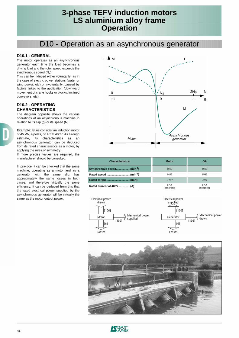
3-phase TEFV induction motorsLS aluminium alloy frame
Operation
84
D10.1 - GENERALThe motor operates as an asynchronousgenerator each time the load becomes adriving load and the rotor speed exceeds thesynchronous speed (Ns).This can be induced either voluntarily, as inthe case of electric power stations (water orwind power, etc) or involuntarily, caused byfactors linked to the application (downwardmovement of crane hooks or blocks, inclinedconveyors, etc).
D10.2 - OPERATING CHARACTERISTICSThe diagram opposite shows the variousoperations of an asynchronous machine inrelation to its slip (g) or its speed (N).
Example: let us consider an induction motorof 45 kW, 4 poles, 50 Hz at 400V. As a roughestimate, its characteristics as anasynchronous generator can be deducedfrom its rated characteristics as a motor, byapplying the rules of symmetry.If more precise values are required, themanufacturer should be consulted.
In practice, it can be checked that the samemachine, operating as a motor and as agenerator with the same slip, hasapproximately the same losses in bothcases, and therefore virtually the sameefficiency. It can be deduced from this thatthe rated electrical power supplied by theasynchronous generator will be virtually thesame as the motor output power.
D10 - Operation as an asynchronous generator
Characteristics Motor GA
Synchronous speed..................(min-1) 1500 1500
Rated speed ..............................(min-1) 1465 1535
Rated torque..............................(m.N) + 287 - 287
Rated current at 400V...............(A) 87 A(absorbed)
87 A(supplied)
M
0
+1
NS
0
2NS
-1
N
g
MotorAsynchronous
generator
I I
M
Mechanical powersupplied
Electrical powerdrawn
Losses
Motor[100]
[106]
[6]
Mechanical powerdrawn
Electrical powersupplied
Losses
Generator[106]
[100]
[6]
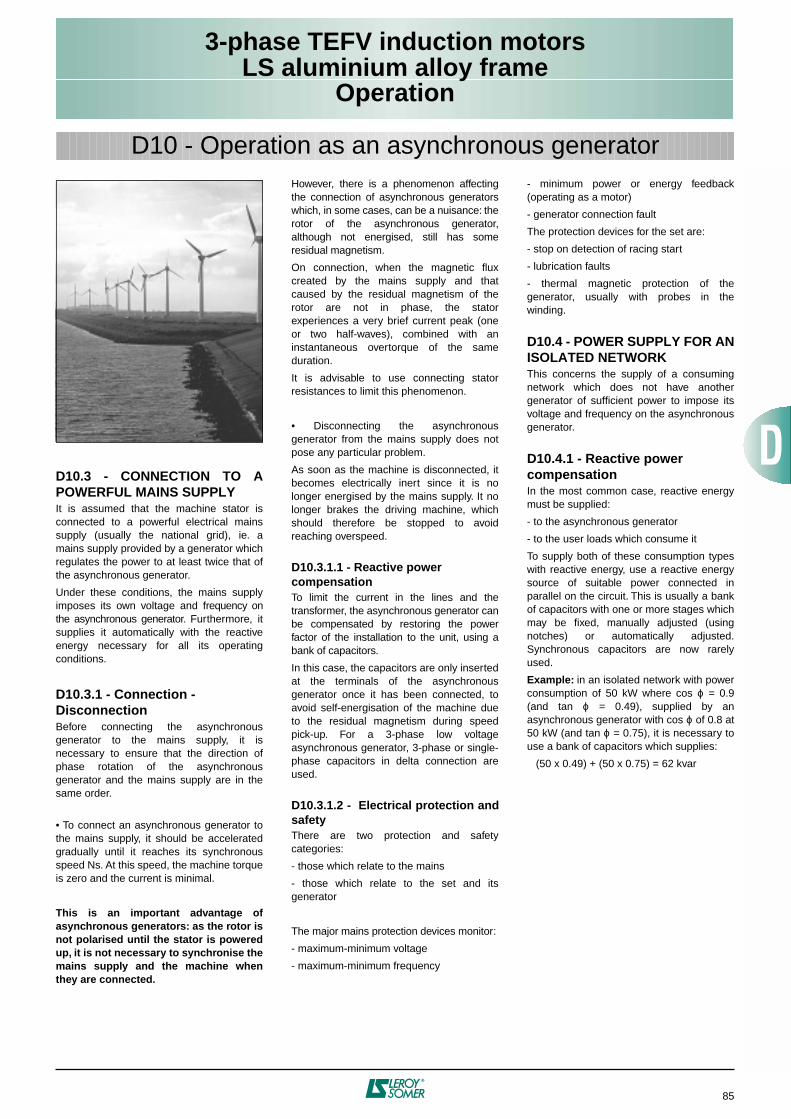
3-phase TEFV induction motorsLS aluminium alloy frame
Operation
85
D10.3 - CONNECTION TO APOWERFUL MAINS SUPPLYIt is assumed that the machine stator isconnected to a powerful electrical mainssupply (usually the national grid), ie. amains supply provided by a generator whichregulates the power to at least twice that ofthe asynchronous generator.
Under these conditions, the mains supplyimposes its own voltage and frequency onthe asynchronous generator. Furthermore, itsupplies it automatically with the reactiveenergy necessary for all its operatingconditions.
D10.3.1 - Connection - DisconnectionBefore connecting the asynchronousgenerator to the mains supply, it isnecessary to ensure that the direction ofphase rotation of the asynchronousgenerator and the mains supply are in thesame order.
• To connect an asynchronous generator tothe mains supply, it should be acceleratedgradually until it reaches its synchronousspeed Ns. At this speed, the machine torqueis zero and the current is minimal.
This is an important advantage ofasynchronous generators: as the rotor isnot polarised until the stator is poweredup, it is not necessary to synchronise themains supply and the machine whenthey are connected.
However, there is a phenomenon affectingthe connection of asynchronous generatorswhich, in some cases, can be a nuisance: therotor of the asynchronous generator,although not energised, still has someresidual magnetism.
On connection, when the magnetic fluxcreated by the mains supply and thatcaused by the residual magnetism of therotor are not in phase, the statorexperiences a very brief current peak (oneor two half-waves), combined with aninstantaneous overtorque of the sameduration.
It is advisable to use connecting statorresistances to limit this phenomenon.
• Disconnecting the asynchronousgenerator from the mains supply does notpose any particular problem.
As soon as the machine is disconnected, itbecomes electrically inert since it is nolonger energised by the mains supply. It nolonger brakes the driving machine, whichshould therefore be stopped to avoidreaching overspeed.
D10.3.1.1 - Reactive power compensationTo limit the current in the lines and thetransformer, the asynchronous generator canbe compensated by restoring the powerfactor of the installation to the unit, using abank of capacitors.
In this case, the capacitors are only insertedat the terminals of the asynchronousgenerator once it has been connected, toavoid self-energisation of the machine dueto the residual magnetism during speedpick-up. For a 3-phase low voltageasynchronous generator, 3-phase or single-phase capacitors in delta connection areused.
D10.3.1.2 - Electrical protection andsafetyThere are two protection and safetycategories:
- those which relate to the mains
- those which relate to the set and itsgenerator
The major mains protection devices monitor:
- maximum-minimum voltage
- maximum-minimum frequency
- minimum power or energy feedback(operating as a motor)
- generator connection fault
The protection devices for the set are:
- stop on detection of racing start
- lubrication faults
- thermal magnetic protection of thegenerator, usually with probes in thewinding.
D10.4 - POWER SUPPLY FOR ANISOLATED NETWORKThis concerns the supply of a consumingnetwork which does not have anothergenerator of sufficient power to impose itsvoltage and frequency on the asynchronousgenerator.
D10.4.1 - Reactive power compensationIn the most common case, reactive energymust be supplied:
- to the asynchronous generator
- to the user loads which consume it
To supply both of these consumption typeswith reactive energy, use a reactive energysource of suitable power connected inparallel on the circuit. This is usually a bankof capacitors with one or more stages whichmay be fixed, manually adjusted (usingnotches) or automatically adjusted.Synchronous capacitors are now rarelyused.
Example: in an isolated network with powerconsumption of 50 kW where cos ϕ = 0.9(and tan ϕ = 0.49), supplied by anasynchronous generator with cos ϕ of 0.8 at50 kW (and tan ϕ = 0.75), it is necessary touse a bank of capacitors which supplies:
(50 x 0.49) + (50 x 0.75) = 62 kvar
D10 - Operation as an asynchronous generator
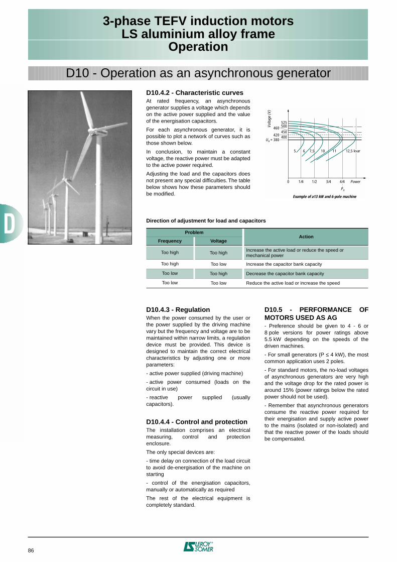
3-phase TEFV induction motorsLS aluminium alloy frame
Operation
86
D10.4.2 - Characteristic curvesAt rated frequency, an asynchronousgenerator supplies a voltage which dependson the active power supplied and the valueof the energisation capacitors.
For each asynchronous generator, it ispossible to plot a network of curves such asthose shown below.
In conclusion, to maintain a constantvoltage, the reactive power must be adaptedto the active power required.
Adjusting the load and the capacitors doesnot present any special difficulties. The tablebelow shows how these parameters shouldbe modified.
525
5
1/40 1/2 3/4 Power
Example of a13 kW and 6-pole machine
Volta
ge (V
)
Pn
6 7,5 10 11
500450
460
420Un = 380
400
12,5 kvar
4/4
D10 - Operation as an asynchronous generator
Direction of adjustment for load and capacitors
ProblemAction
Frequency Voltage
Too high Too high Increase the active load or reduce the speed ormechanical power
Too high Too low Increase the capacitor bank capacity
Too low Too high Decrease the capacitor bank capacity
Too low Too low Reduce the active load or increase the speed
D10.4.3 - RegulationWhen the power consumed by the user orthe power supplied by the driving machinevary but the frequency and voltage are to bemaintained within narrow limits, a regulationdevice must be provided. This device isdesigned to maintain the correct electricalcharacteristics by adjusting one or moreparameters:
- active power supplied (driving machine)
- active power consumed (loads on thecircuit in use)
- reactive power supplied (usuallycapacitors).
D10.4.4 - Control and protectionThe installation comprises an electricalmeasuring, control and protectionenclosure.
The only special devices are:
- time delay on connection of the load circuitto avoid de-energisation of the machine onstarting
- control of the energisation capacitors,manually or automatically as required
The rest of the electrical equipment iscompletely standard.
D10.5 - PERFORMANCE OFMOTORS USED AS AG- Preference should be given to 4 - 6 or8 pole versions for power ratings above5.5 kW depending on the speeds of thedriven machines.
- For small generators (P ≤ 4 kW), the mostcommon application uses 2 poles.
- For standard motors, the no-load voltagesof asynchronous generators are very highand the voltage drop for the rated power isaround 15% (power ratings below the ratedpower should not be used).
- Remember that asynchronous generatorsconsume the reactive power required fortheir energisation and supply active powerto the mains (isolated or non-isolated) andthat the reactive power of the loads shouldbe compensated.
3-phase TEFV induction motorsLS aluminium alloy frameElectrical characteristics
87
PAGES
2 poles - 3000 min
–1
............................................................................
88 - 89
4 poles - 1500 min
–1
.............................................................................
90 -91
6 poles - 1000 min
–1
.............................................................................
92 -93
8 poles - 750 min
–1
...............................................................................
94 -95
Centrifugal applications
2 / 4 poles - 3000 / 1500 min
-1
..................................................................
96
4 / 6 poles - 1500 / 1000 min
-1 (2 separate windings)
.....................................
97
4 / 6 poles - 1500 / 1000 min
-1 (1 PAM winding)
............................................
98
4 / 8 poles - 1500 / 750 min
-1
....................................................................
99
6 / 12 poles - 1000 / 500 min
-1
................................................................
100
General table of two-speed motors
Centrifugal applications
..........................................................................
101
General applications................................................................................
102
For dimensions, see section
page 103
E1 - Selection data: single speed
E2 - Selection data: two-speed
F
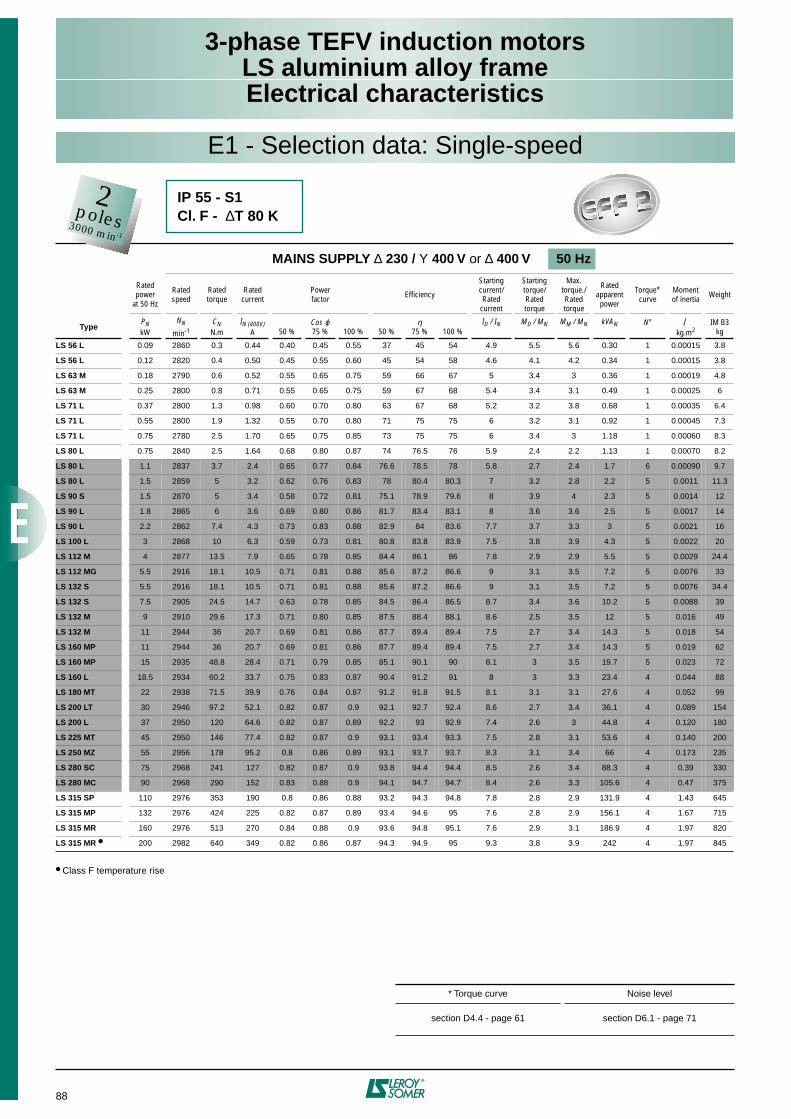
88
3-phase TEFV induction motorsLS aluminium alloy frameElectrical characteristics
E1 - Selection data: Single-speed
Class F temperature rise
MAINS SUPPLY
∆
230 /
Υ
400 V
or
∆
400 V 50 Hz
Ratedpower
at 50 Hz
Rated speed
Rated torque
Rated current
Powerfactor Efficiency
Startingcurrent/Rated
current
Startingtorque/Ratedtorque
Max.torque./Ratedtorque
Rated apparentpower
Torque*curve
Moment of inertia Weight
Type
P
N
kW
N
N
min
-1
C
N
N.m
I
N (400V)
A 50 %
Cos
ϕ
75 % 100 % 50 %
η
75 % 100 %
I
D
/ I
N
M
D
/ M
N
M
M
/ M
N
kVA
N
N° J
kg.m
2
IM B3kg
LS 56 L
0.09 2860 0.3 0.44 0.40 0.45 0.55 37 45 54 4.9 5.5 5.6 0.30 1 0.00015 3.8
LS 56 L
0.12 2820 0.4 0.50 0.45 0.55 0.60 45 54 58 4.6 4.1 4.2 0.34 1 0.00015 3.8
LS 63 M
0.18 2790 0.6 0.52 0.55 0.65 0.75 59 66 67 5 3.4 3 0.36 1 0.00019 4.8
LS 63 M
0.25 2800 0.8 0.71 0.55 0.65 0.75 59 67 68 5.4 3.4 3.1 0.49 1 0.00025 6
LS 71 L
0.37 2800 1.3 0.98 0.60 0.70 0.80 63 67 68 5.2 3.2 3.8 0.68 1 0.00035 6.4
LS 71 L
0.55 2800 1.9 1.32 0.55 0.70 0.80 71 75 75 6 3.2 3.1 0.92 1 0.00045 7.3
LS 71 L
0.75 2780 2.5 1.70 0.65 0.75 0.85 73 75 75 6 3.4 3 1.18 1 0.00060 8.3
LS 80 L
0.75 2840 2.5 1.64 0.68 0.80 0.87 74 76.5 76 5.9 2.4 2.2 1.13 1 0.00070 8.2
LS 80 L
1.1 2837 3.7 2.4 0.65 0.77 0.84 76.6 78.5 78 5.8 2.7 2.4 1.7 6 0.00090 9.7
LS 80 L
1.5 2859 5 3.2 0.62 0.76 0.83 78 80.4 80.3 7 3.2 2.8 2.2 5 0.0011 11.3
LS 90 S
1.5 2870 5 3.4 0.58 0.72 0.81 75.1 78.9 79.6 8 3.9 4 2.3 5 0.0014 12
LS 90 L
1.8 2865 6 3.6 0.69 0.80 0.86 81.7 83.4 83.1 8 3.6 3.6 2.5 5 0.0017 14
LS 90 L
2.2 2862 7.4 4.3 0.73 0.83 0.88 82.9 84 83.6 7.7 3.7 3.3 3 5 0.0021 16
LS 100 L
3 2868 10 6.3 0.59 0.73 0.81 80.8 83.8 83.9 7.5 3.8 3.9 4.3 5 0.0022 20
LS 112 M
4 2877 13.5 7.9 0.65 0.78 0.85 84.4 86.1 86 7.8 2.9 2.9 5.5 5 0.0029 24.4
LS 112 MG
5.5 2916 18.1 10.5 0.71 0.81 0.88 85.6 87.2 86.6 9 3.1 3.5 7.2 5 0.0076 33
LS 132 S
5.5 2916 18.1 10.5 0.71 0.81 0.88 85.6 87.2 86.6 9 3.1 3.5 7.2 5 0.0076 34.4
LS 132 S
7.5 2905 24.5 14.7 0.63 0.78 0.85 84.5 86.4 86.5 8.7 3.4 3.6 10.2 5 0.0088 39
LS 132 M
9 2910 29.6 17.3 0.71 0.80 0.85 87.5 88.4 88.1 8.6 2.5 3.5 12 5 0.016 49
LS 132 M
11 2944 36 20.7 0.69 0.81 0.86 87.7 89.4 89.4 7.5 2.7 3.4 14.3 5 0.018 54
LS 160 MP
11 2944 36 20.7 0.69 0.81 0.86 87.7 89.4 89.4 7.5 2.7 3.4 14.3 5 0.019 62
LS 160 MP
15 2935 48.8 28.4 0.71 0.79 0.85 85.1 90.1 90 8.1 3 3.5 19.7 5 0.023 72
LS 160 L
18.5 2934 60.2 33.7 0.75 0.83 0.87 90.4 91.2 91 8 3 3.3 23.4 4 0.044 88
LS 180 MT
22 2938 71.5 39.9 0.76 0.84 0.87 91.2 91.8 91.5 8.1 3.1 3.1 27.6 4 0.052 99
LS 200 LT
30 2946 97.2 52.1 0.82 0.87 0.9 92.1 92.7 92.4 8.6 2.7 3.4 36.1 4 0.089 154
LS 200 L
37 2950 120 64.6 0.82 0.87 0.89 92.2 93 92.9 7.4 2.6 3 44.8 4 0.120 180
LS 225 MT
45 2950 146 77.4 0.82 0.87 0.9 93.1 93.4 93.3 7.5 2.8 3.1 53.6 4 0.140 200
LS 250 MZ
55 2956 178 95.2 0.8 0.86 0.89 93.1 93.7 93.7 8.3 3.1 3.4 66 4 0.173 235
LS 280 SC
75 2968 241 127 0.82 0.87 0.9 93.8 94.4 94.4 8.5 2.6 3.4 88.3 4 0.39 330
LS 280 MC
90 2968 290 152 0.83 0.88 0.9 94.1 94.7 94.7 8.4 2.6 3.3 105.6 4 0.47 375
LS 315 SP
110 2976 353 190 0.8 0.86 0.88 93.2 94.3 94.8 7.8 2.8 2.9 131.9 4 1.43 645
LS 315 MP
132 2976 424 225 0.82 0.87 0.89 93.4 94.6 95 7.6 2.8 2.9 156.1 4 1.67 715
LS 315 MR
160 2976 513 270 0.84 0.88 0.9 93.6 94.8 95.1 7.6 2.9 3.1 186.9 4 1.97 820
LS 315 MR
200 2982 640 349 0.82 0.86 0.87 94.3 94.9 95 9.3 3.8 3.9 242 4 1.97 845
* Torque curve Noise level
section D4.4 - page 61 section D6.1 - page 71
2poles3000 min-1
IP 55 - S1Cl. F -
∆
T 80 K
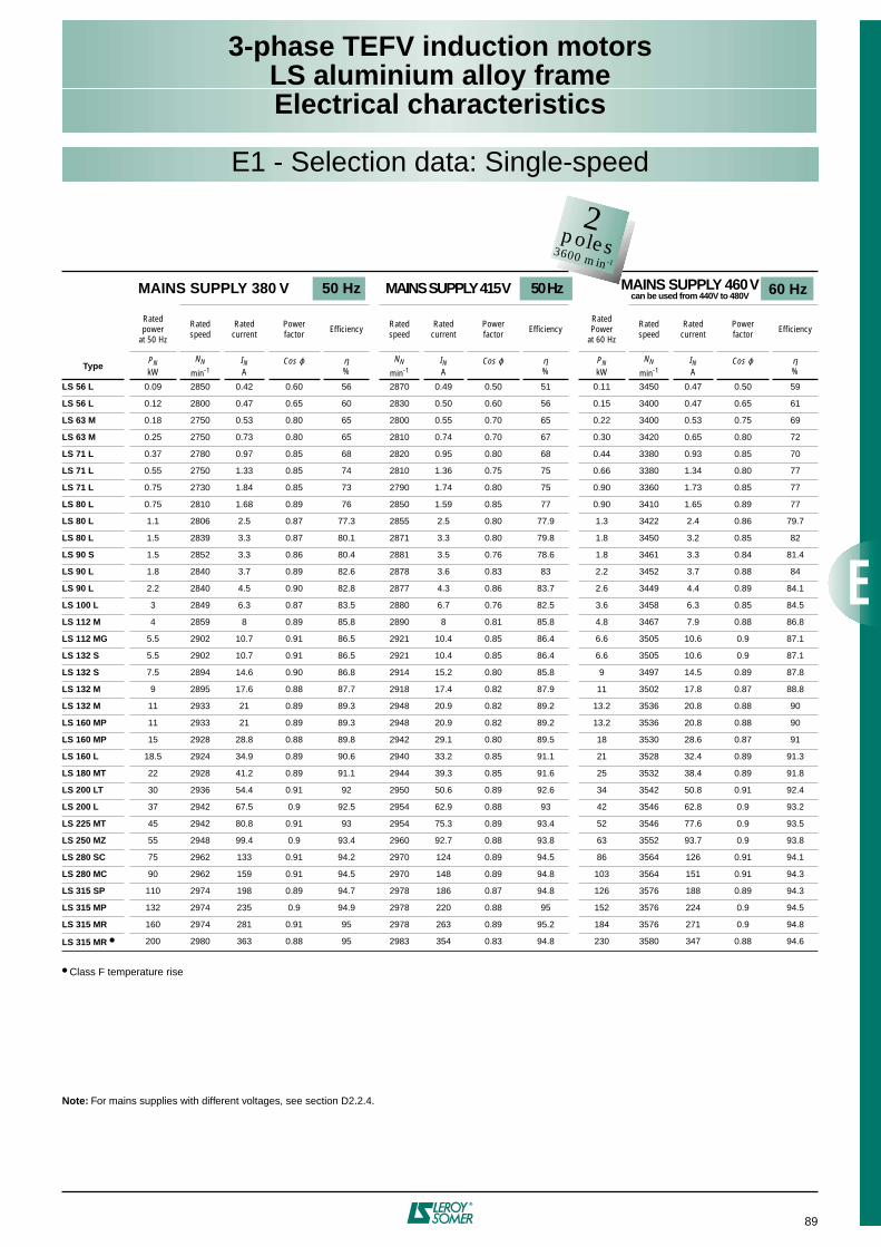
89
3-phase TEFV induction motorsLS aluminium alloy frameElectrical characteristics
Class F temperature rise
Note:
For mains supplies with different voltages, see section D2.2.4.
MAINS SUPPLY 380 V 50 Hz MAINS SUPPLY 415 V 50 Hz MAINS SUPPLY 460 V
can be used from 440V to 480V
Ratedpower
at 50 Hz
Rated speed
Rated current
Powerfactor Efficiency Rated
speedRated
currentPowerfactor Efficiency
RatedPower
at 60 Hz
Rated speed
Rated current
Powerfactor Efficiency
Type
P
N
kW
N
N
min
-1
I
N
A
Cos
ϕ η
%
N
N
min
-1
I
N
A
Cos
ϕ η
%
P
N
kW
N
N
min
-1
I
N
A
Cos
ϕ η
%
LS 56 L
0.09 2850 0.42 0.60 56 2870 0.49 0.50 51 0.11 3450 0.47 0.50 59
LS 56 L
0.12 2800 0.47 0.65 60 2830 0.50 0.60 56 0.15 3400 0.47 0.65 61
LS 63 M
0.18 2750 0.53 0.80 65 2800 0.55 0.70 65 0.22 3400 0.53 0.75 69
LS 63 M
0.25 2750 0.73 0.80 65 2810 0.74 0.70 67 0.30 3420 0.65 0.80 72
LS 71 L
0.37 2780 0.97 0.85 68 2820 0.95 0.80 68 0.44 3380 0.93 0.85 70
LS 71 L
0.55 2750 1.33 0.85 74 2810 1.36 0.75 75 0.66 3380 1.34 0.80 77
LS 71 L
0.75 2730 1.84 0.85 73 2790 1.74 0.80 75 0.90 3360 1.73 0.85 77
LS 80 L
0.75 2810 1.68 0.89 76 2850 1.59 0.85 77 0.90 3410 1.65 0.89 77
LS 80 L
1.1 2806 2.5 0.87 77.3 2855 2.5 0.80 77.9 1.3 3422 2.4 0.86 79.7
LS 80 L
1.5 2839 3.3 0.87 80.1 2871 3.3 0.80 79.8 1.8 3450 3.2 0.85 82
LS 90 S
1.5 2852 3.3 0.86 80.4 2881 3.5 0.76 78.6 1.8 3461 3.3 0.84 81.4
LS 90 L
1.8 2840 3.7 0.89 82.6 2878 3.6 0.83 83 2.2 3452 3.7 0.88 84
LS 90 L
2.2 2840 4.5 0.90 82.8 2877 4.3 0.86 83.7 2.6 3449 4.4 0.89 84.1
LS 100 L
3 2849 6.3 0.87 83.5 2880 6.7 0.76 82.5 3.6 3458 6.3 0.85 84.5
LS 112 M
4 2859 8 0.89 85.8 2890 8 0.81 85.8 4.8 3467 7.9 0.88 86.8
LS 112 MG
5.5 2902 10.7 0.91 86.5 2921 10.4 0.85 86.4 6.6 3505 10.6 0.9 87.1
LS 132 S
5.5 2902 10.7 0.91 86.5 2921 10.4 0.85 86.4 6.6 3505 10.6 0.9 87.1
LS 132 S
7.5 2894 14.6 0.90 86.8 2914 15.2 0.80 85.8 9 3497 14.5 0.89 87.8
LS 132 M
9 2895 17.6 0.88 87.7 2918 17.4 0.82 87.9 11 3502 17.8 0.87 88.8
LS 132 M
11 2933 21 0.89 89.3 2948 20.9 0.82 89.2 13.2 3536 20.8 0.88 90
LS 160 MP
11 2933 21 0.89 89.3 2948 20.9 0.82 89.2 13.2 3536 20.8 0.88 90
LS 160 MP
15 2928 28.8 0.88 89.8 2942 29.1 0.80 89.5 18 3530 28.6 0.87 91
LS 160 L
18.5 2924 34.9 0.89 90.6 2940 33.2 0.85 91.1 21 3528 32.4 0.89 91.3
LS 180 MT 22 2928 41.2 0.89 91.1 2944 39.3 0.85 91.6 25 3532 38.4 0.89 91.8
LS 200 LT 30 2936 54.4 0.91 92 2950 50.6 0.89 92.6 34 3542 50.8 0.91 92.4
LS 200 L 37 2942 67.5 0.9 92.5 2954 62.9 0.88 93 42 3546 62.8 0.9 93.2
LS 225 MT 45 2942 80.8 0.91 93 2954 75.3 0.89 93.4 52 3546 77.6 0.9 93.5
LS 250 MZ 55 2948 99.4 0.9 93.4 2960 92.7 0.88 93.8 63 3552 93.7 0.9 93.8
LS 280 SC 75 2962 133 0.91 94.2 2970 124 0.89 94.5 86 3564 126 0.91 94.1
LS 280 MC 90 2962 159 0.91 94.5 2970 148 0.89 94.8 103 3564 151 0.91 94.3
LS 315 SP 110 2974 198 0.89 94.7 2978 186 0.87 94.8 126 3576 188 0.89 94.3
LS 315 MP 132 2974 235 0.9 94.9 2978 220 0.88 95 152 3576 224 0.9 94.5
LS 315 MR 160 2974 281 0.91 95 2978 263 0.89 95.2 184 3576 271 0.9 94.8
LS 315 MR 200 2980 363 0.88 95 2983 354 0.83 94.8 230 3580 347 0.88 94.6
60 Hz
E1 - Selection data: Single-speed
2poles3600 min-1
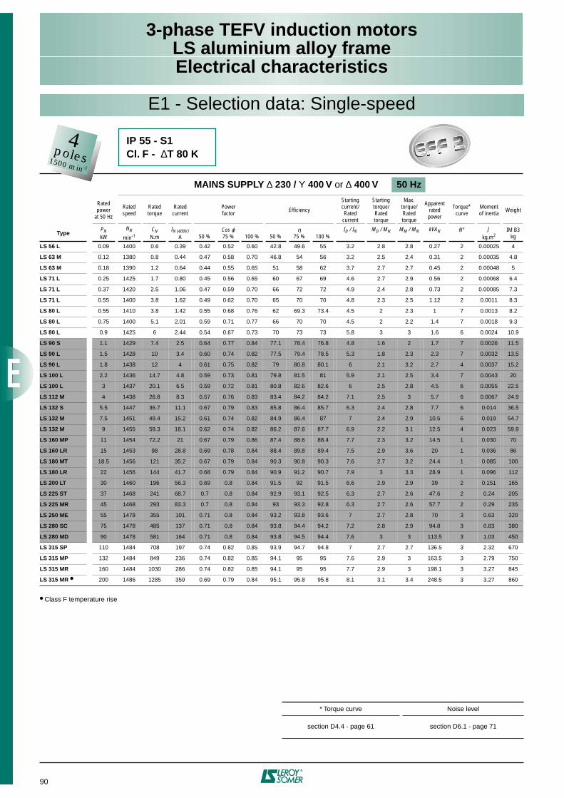
90
3-phase TEFV induction motorsLS aluminium alloy frameElectrical characteristics
Class F temperature rise
MAINS SUPPLY ∆ 230 / Υ 400 V or ∆ 400 V 50 Hz
Ratedpower
at 50 Hz
Rated speed
Rated torque
Rated current
Powerfactor Efficiency
Startingcurrent/Rated
current
Startingtorque/Ratedtorque
Max.torque/Ratedtorque
Apparent ratedpower
Torque*curve
Moment of inertia Weight
TypePNkW
NN
min-1CN
N.mIN (400V)
A 50 %Cos ϕ75 % 100 % 50 %
η75 % 100 %
ID / IN MD / MN MM / MN kVAN N° Jkg.m2
IM B3kg
LS 56 L 0.09 1400 0.6 0.39 0.42 0.52 0.60 42.8 49.6 55 3.2 2.8 2.8 0.27 2 0.00025 4
LS 63 M 0.12 1380 0.8 0.44 0.47 0.58 0.70 46.8 54 56 3.2 2.5 2.4 0.31 2 0.00035 4.8
LS 63 M 0.18 1390 1.2 0.64 0.44 0.55 0.65 51 58 62 3.7 2.7 2.7 0.45 2 0.00048 5
LS 71 L 0.25 1425 1.7 0.80 0.45 0.56 0.65 60 67 69 4.6 2.7 2.9 0.56 2 0.00068 6.4
LS 71 L 0.37 1420 2.5 1.06 0.47 0.59 0.70 66 72 72 4.9 2.4 2.8 0.73 2 0.00085 7.3
LS 71 L 0.55 1400 3.8 1.62 0.49 0.62 0.70 65 70 70 4.8 2.3 2.5 1.12 2 0.0011 8.3
LS 80 L 0.55 1410 3.8 1.42 0.55 0.68 0.76 62 69.3 73.4 4.5 2 2.3 1 7 0.0013 8.2
LS 80 L 0.75 1400 5.1 2.01 0.59 0.71 0.77 66 70 70 4.5 2 2.2 1.4 7 0.0018 9.3
LS 80 L 0.9 1425 6 2.44 0.54 0.67 0.73 70 73 73 5.8 3 3 1.6 6 0.0024 10.9
LS 90 S 1.1 1429 7.4 2.5 0.64 0.77 0.84 77.1 78.4 76.8 4.8 1.6 2 1.7 7 0.0026 11.5
LS 90 L 1.5 1428 10 3.4 0.60 0.74 0.82 77.5 79.4 78.5 5.3 1.8 2.3 2.3 7 0.0032 13.5
LS 90 L 1.8 1438 12 4 0.61 0.75 0.82 79 80.8 80.1 6 2.1 3.2 2.7 4 0.0037 15.2
LS 100 L 2.2 1436 14.7 4.8 0.59 0.73 0.81 79.8 81.5 81 5.9 2.1 2.5 3.4 7 0.0043 20
LS 100 L 3 1437 20.1 6.5 0.59 0.72 0.81 80.8 82.6 82.6 6 2.5 2.8 4.5 6 0.0055 22.5
LS 112 M 4 1438 26.8 8.3 0.57 0.76 0.83 83.4 84.2 84.2 7.1 2.5 3 5.7 6 0.0067 24.9
LS 132 S 5.5 1447 36.7 11.1 0.67 0.79 0.83 85.8 86.4 85.7 6.3 2.4 2.8 7.7 6 0.014 36.5
LS 132 M 7.5 1451 49.4 15.2 0.61 0.74 0.82 84.9 86.4 87 7 2.4 2.9 10.5 6 0.019 54.7
LS 132 M 9 1455 59.3 18.1 0.62 0.74 0.82 86.2 87.6 87.7 6.9 2.2 3.1 12.5 4 0.023 59.9
LS 160 MP 11 1454 72.2 21 0.67 0.79 0.86 87.4 88.6 88.4 7.7 2.3 3.2 14.5 1 0.030 70
LS 160 LR 15 1453 98 28.8 0.69 0.78 0.84 88.4 89.8 89.4 7.5 2.9 3.6 20 1 0.036 86
LS 180 MT 18.5 1456 121 35.2 0.67 0.79 0.84 90.3 90.8 90.3 7.6 2.7 3.2 24.4 1 0.085 100
LS 180 LR 22 1456 144 41.7 0.68 0.79 0.84 90.9 91.2 90.7 7.9 3 3.3 28.9 1 0.096 112
LS 200 LT 30 1460 196 56.3 0.69 0.8 0.84 91.5 92 91.5 6.6 2.9 2.9 39 2 0.151 165
LS 225 ST 37 1468 241 68.7 0.7 0.8 0.84 92.9 93.1 92.5 6.3 2.7 2.6 47.6 2 0.24 205
LS 225 MR 45 1468 293 83.3 0.7 0.8 0.84 93 93.3 92.8 6.3 2.7 2.6 57.7 2 0.29 235
LS 250 ME 55 1478 355 101 0.71 0.8 0.84 93.2 93.8 93.6 7 2.7 2.8 70 3 0.63 320
LS 280 SC 75 1478 485 137 0.71 0.8 0.84 93.8 94.4 94.2 7.2 2.8 2.9 94.8 3 0.83 380
LS 280 MD 90 1478 581 164 0.71 0.8 0.84 93.8 94.5 94.4 7.6 3 3 113.5 3 1.03 450
LS 315 SP 110 1484 708 197 0.74 0.82 0.85 93.9 94.7 94.8 7 2.7 2.7 136.5 3 2.32 670
LS 315 MP 132 1484 849 236 0.74 0.82 0.85 94.1 95 95 7.6 2.9 3 163.5 3 2.79 750
LS 315 MR 160 1484 1030 286 0.74 0.82 0.85 94.1 95 95 7.7 2.9 3 198.1 3 3.27 845
LS 315 MR 200 1486 1285 359 0.69 0.79 0.84 95.1 95.8 95.8 8.1 3.1 3.4 248.5 3 3.27 860
* Torque curve Noise level
section D4.4 - page 61 section D6.1 - page 71
E1 - Selection data: Single-speed
4poles1500 min-1
IP 55 - S1Cl. F - ∆T 80 K
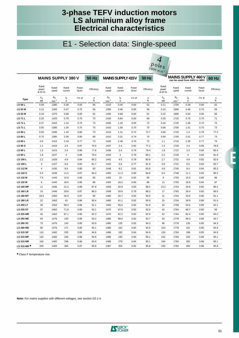
91
3-phase TEFV induction motorsLS aluminium alloy frameElectrical characteristics
E1 - Selection data: Single-speed
Class F temperature rise
Note: For mains supplies with different voltages, see section D2.2.4.
MAINS SUPPLY 380 V 50 Hz MAINS SUPPLY 415 V 50 Hz MAINS SUPPLY 460 V can be used from 440V to 480V
Ratedpower
at 50 Hz
Rated speed
Rated current
Powerfactor Efficiency Rated
speedRated
currentPowerfactor Efficiency
Ratedpower
at 60 Hz
Rated speed
Rated current
Powerfactor Efficiency
TypePNkW
NN
min-1IN A
Cos ϕ η%
NN
min-1IN A
Cos ϕ η%
PNkW
NN
min-1IN A
Cos ϕ η%
LS 56 L 0.09 1380 0.38 0.65 56 1410 0.40 0.60 52 0.11 1700 0.36 0.60 62
LS 63 M 0.12 1365 0.47 0.70 56 1390 0.46 0.65 56 0.15 1680 0.46 0.70 59
LS 63 M 0.18 1375 0.68 0.65 62 1400 0.68 0.60 61 0.22 1690 0.64 0.65 65
LS 71 L 0.25 1425 0.78 0.70 70 1430 0.84 0.60 69 0.30 1720 0.76 0.70 71
LS 71 L 0.37 1410 1.10 0.70 73 1430 1.10 0.65 72 0.44 1720 1.06 0.70 75
LS 71 L 0.55 1385 1.59 0.75 70 1410 1.56 0.70 70 0.66 1700 1.51 0.75 73
LS 80 L 0.55 1396 1.43 0.80 73 1415 1.41 0.74 72.7 0.66 1725 1.4 0.78 77.3
LS 80 L 0.75 1380 2.06 0.80 69 1410 2.01 0.74 70 0.90 1700 2.01 0.77 73
LS 80 L 0.9 1415 2.43 0.77 73 1435 2.48 0.70 72 1.1 1710 2.39 0.77 75
LS 90 S 1.1 1416 2.5 0.87 75.5 1437 2.4 0.82 77.2 1.3 1726 2.4 0.85 78.9
LS 90 L 1.5 1415 3.4 0.86 77.6 1436 3.4 0.79 78.4 1.8 1722 3.3 0.84 80.4
LS 90 L 1.8 1427 4 0.85 79.4 1443 4 0.79 80.1 2.2 1733 4 0.84 81.9
LS 100 L 2.2 1426 4.9 0.84 80.2 1442 4.9 0.78 80.6 2.7 1731 4.8 0.82 82.6
LS 100 L 3 1427 6.6 0.84 81.7 1443 6.6 0.77 81.9 3.6 1731 6.5 0.83 83.7
LS 112 M 4 1430 8.6 0.85 83 1448 8.2 0.81 83.6 4.8 1740 8.4 0.84 85.3
LS 132 S 5.5 1438 11.5 0.87 84.3 1450 11.3 0.80 84.6 6.6 1748 11.1 0.83 86.2
LS 132 M 7.5 1445 15.8 0.85 85 1455 15 0.82 85 9 1750 15.5 0.85 86
LS 132 M 9 1440 18.5 0.86 86 1455 18.2 0.80 86 11 1750 18.9 0.84 87
LS 160 MP 11 1446 21.5 0.89 87.8 1458 20.9 0.83 88.2 13.2 1754 20.8 0.85 89.2
LS 160 LR 15 1446 29.8 0.87 88.3 1458 29.9 0.79 88.3 17 1762 29.4 0.82 89.5
LS 180 MT 18.5 1450 35.9 0.87 90 1460 34.7 0.82 90.5 21 1754 33.6 0.86 91.1
LS 180 LR 22 1450 43 0.86 90.4 1460 41.1 0.82 90.9 25 1754 39.9 0.86 91.5
LS 200 LT 30 1454 58.2 0.86 91.1 1464 55.6 0.82 91.6 34 1758 54.5 0.85 92.1
LS 225 ST 37 1462 71.8 0.85 92.1 1470 67.8 0.82 92.6 42 1764 66.7 0.85 93
LS 225 MR 45 1462 87.1 0.85 92.3 1470 82.2 0.82 92.9 52 1764 82.4 0.85 93.2
LS 250 ME 55 1476 105 0.85 93.2 1480 99.6 0.82 93.7 63 1778 99.3 0.85 93.7
LS 280 SC 75 1476 143 0.85 93.9 1480 135 0.82 94.3 86 1778 135 0.85 94.3
LS 280 MD 90 1476 171 0.85 94.1 1480 162 0.82 94.5 103 1778 161 0.85 94.5
LS 315 SP 110 1482 205 0.86 94.6 1486 192 0.84 94.9 126 1784 196 0.85 94.9
LS 315 MP 132 1482 246 0.86 94.9 1486 230 0.84 95.1 152 1784 233 0.86 95.1
LS 315 MR 160 1482 298 0.86 94.9 1486 279 0.84 95.1 184 1784 282 0.86 95.1
LS 315 MR 200 1484 365 0.87 95.8 1487 354 0.82 95.8 230 1784 350 0.86 95.9
4poles1800 min-1
60 Hz
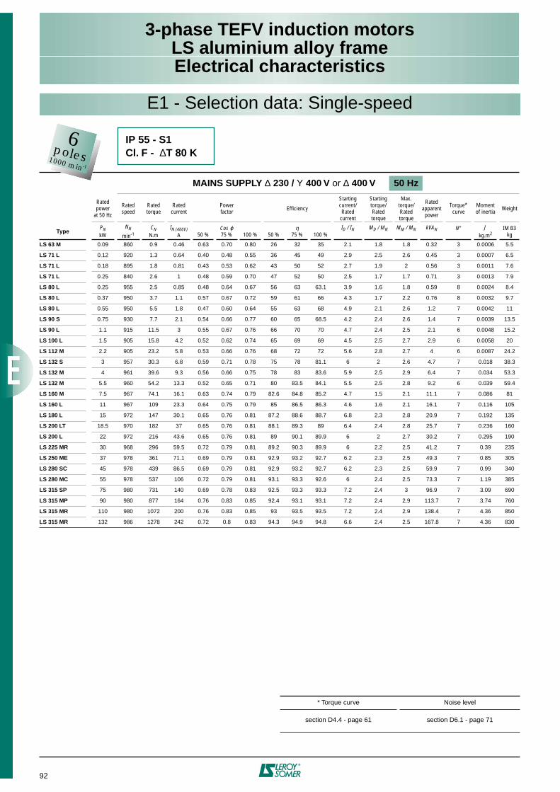
92
3-phase TEFV induction motorsLS aluminium alloy frameElectrical characteristics
MAINS SUPPLY ∆ 230 / Υ 400 V or ∆ 400 V 50 Hz
Ratedpower
at 50 Hz
Rated speed
Rated torque
Rated current
Powerfactor Efficiency
Starting current/Rated
current
Starting torque/Rated torque
Max. torque/Ratedtorque
Rated apparentpower
Torque*curve
Moment of inertia Weight
TypePNkW
NN
min-1CN
N.mIN (400V)
A 50 %Cos ϕ75 % 100 % 50 %
η75 % 100 %
ID / IN MD / MN MM / MN kVAN N° Jkg.m2
IM B3kg
LS 63 M 0.09 860 0.9 0.46 0.63 0.70 0.80 26 32 35 2.1 1.8 1.8 0.32 3 0.0006 5.5
LS 71 L 0.12 920 1.3 0.64 0.40 0.48 0.55 36 45 49 2.9 2.5 2.6 0.45 3 0.0007 6.5
LS 71 L 0.18 895 1.8 0.81 0.43 0.53 0.62 43 50 52 2.7 1.9 2 0.56 3 0.0011 7.6
LS 71 L 0.25 840 2.6 1 0.48 0.59 0.70 47 52 50 2.5 1.7 1.7 0.71 3 0.0013 7.9
LS 80 L 0.25 955 2.5 0.85 0.48 0.64 0.67 56 63 63.1 3.9 1.6 1.8 0.59 8 0.0024 8.4
LS 80 L 0.37 950 3.7 1.1 0.57 0.67 0.72 59 61 66 4.3 1.7 2.2 0.76 8 0.0032 9.7
LS 80 L 0.55 950 5.5 1.8 0.47 0.60 0.64 55 63 68 4.9 2.1 2.6 1.2 7 0.0042 11
LS 90 S 0.75 930 7.7 2.1 0.54 0.66 0.77 60 65 68.5 4.2 2.4 2.6 1.4 7 0.0039 13.5
LS 90 L 1.1 915 11.5 3 0.55 0.67 0.76 66 70 70 4.7 2.4 2.5 2.1 6 0.0048 15.2
LS 100 L 1.5 905 15.8 4.2 0.52 0.62 0.74 65 69 69 4.5 2.5 2.7 2.9 6 0.0058 20
LS 112 M 2.2 905 23.2 5.8 0.53 0.66 0.76 68 72 72 5.6 2.8 2.7 4 6 0.0087 24.2
LS 132 S 3 957 30.3 6.8 0.59 0.71 0.78 75 78 81.1 6 2 2.6 4.7 7 0.018 38.3
LS 132 M 4 961 39.6 9.3 0.56 0.66 0.75 78 83 83.6 5.9 2.5 2.9 6.4 7 0.034 53.3
LS 132 M 5.5 960 54.2 13.3 0.52 0.65 0.71 80 83.5 84.1 5.5 2.5 2.8 9.2 6 0.039 59.4
LS 160 M 7.5 967 74.1 16.1 0.63 0.74 0.79 82.6 84.8 85.2 4.7 1.5 2.1 11.1 7 0.086 81
LS 160 L 11 967 109 23.3 0.64 0.75 0.79 85 86.5 86.3 4.6 1.6 2.1 16.1 7 0.116 105
LS 180 L 15 972 147 30.1 0.65 0.76 0.81 87.2 88.6 88.7 6.8 2.3 2.8 20.9 7 0.192 135
LS 200 LT 18.5 970 182 37 0.65 0.76 0.81 88.1 89.3 89 6.4 2.4 2.8 25.7 7 0.236 160
LS 200 L 22 972 216 43.6 0.65 0.76 0.81 89 90.1 89.9 6 2 2.7 30.2 7 0.295 190
LS 225 MR 30 968 296 59.5 0.72 0.79 0.81 89.2 90.3 89.9 6 2.2 2.5 41.2 7 0.39 235
LS 250 ME 37 978 361 71.1 0.69 0.79 0.81 92.9 93.2 92.7 6.2 2.3 2.5 49.3 7 0.85 305
LS 280 SC 45 978 439 86.5 0.69 0.79 0.81 92.9 93.2 92.7 6.2 2.3 2.5 59.9 7 0.99 340
LS 280 MC 55 978 537 106 0.72 0.79 0.81 93.1 93.3 92.6 6 2.4 2.5 73.3 7 1.19 385
LS 315 SP 75 980 731 140 0.69 0.78 0.83 92.5 93.3 93.3 7.2 2.4 3 96.9 7 3.09 690
LS 315 MP 90 980 877 164 0.76 0.83 0.85 92.4 93.1 93.1 7.2 2.4 2.9 113.7 7 3.74 760
LS 315 MR 110 980 1072 200 0.76 0.83 0.85 93 93.5 93.5 7.2 2.4 2.9 138.4 7 4.36 850
LS 315 MR 132 986 1278 242 0.72 0.8 0.83 94.3 94.9 94.8 6.6 2.4 2.5 167.8 7 4.36 830
* Torque curve Noise level
section D4.4 - page 61 section D6.1 - page 71
E1 - Selection data: Single-speed
IP 55 - S1Cl. F - ∆T 80 K
6poles1000 min-1
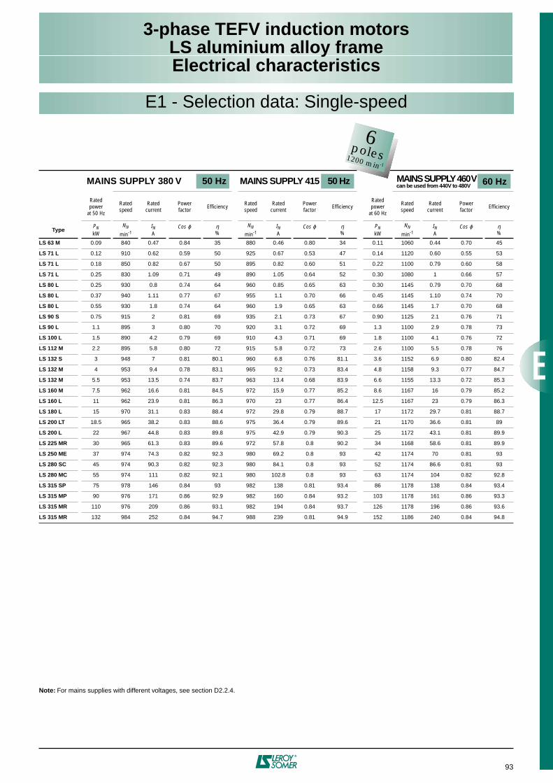
93
3-phase TEFV induction motorsLS aluminium alloy frameElectrical characteristics
60 Hz
E1 - Selection data: Single-speed
Note: For mains supplies with different voltages, see section D2.2.4.
MAINS SUPPLY 380 V 50 Hz MAINS SUPPLY 415 50 Hz MAINS SUPPLY 460 V can be used from 440V to 480V
Ratedpower
at 50 Hz
Rated speed
Rated current
Powerfactor Efficiency Rated
speedRated
currentPowerfactor Efficiency
Ratedpower
at 60 Hz
Rated speed
Rated current
Powerfactor Efficiency
TypePNkW
NN
min-1IN A
Cos ϕ η%
NN
min-1IN A
Cos ϕ η%
PNkW
NN
min-1IN A
Cos ϕ η%
LS 63 M 0.09 840 0.47 0.84 35 880 0.46 0.80 34 0.11 1060 0.44 0.70 45
LS 71 L 0.12 910 0.62 0.59 50 925 0.67 0.53 47 0.14 1120 0.60 0.55 53
LS 71 L 0.18 850 0.82 0.67 50 895 0.82 0.60 51 0.22 1100 0.79 0.60 58
LS 71 L 0.25 830 1.09 0.71 49 890 1.05 0.64 52 0.30 1080 1 0.66 57
LS 80 L 0.25 930 0.8 0.74 64 960 0.85 0.65 63 0.30 1145 0.79 0.70 68
LS 80 L 0.37 940 1.11 0.77 67 955 1.1 0.70 66 0.45 1145 1.10 0.74 70
LS 80 L 0.55 930 1.8 0.74 64 960 1.9 0.65 63 0.66 1145 1.7 0.70 68
LS 90 S 0.75 915 2 0.81 69 935 2.1 0.73 67 0.90 1125 2.1 0.76 71
LS 90 L 1.1 895 3 0.80 70 920 3.1 0.72 69 1.3 1100 2.9 0.78 73
LS 100 L 1.5 890 4.2 0.79 69 910 4.3 0.71 69 1.8 1100 4.1 0.76 72
LS 112 M 2.2 895 5.8 0.80 72 915 5.8 0.72 73 2.6 1100 5.5 0.78 76
LS 132 S 3 948 7 0.81 80.1 960 6.8 0.76 81.1 3.6 1152 6.9 0.80 82.4
LS 132 M 4 953 9.4 0.78 83.1 965 9.2 0.73 83.4 4.8 1158 9.3 0.77 84.7
LS 132 M 5.5 953 13.5 0.74 83.7 963 13.4 0.68 83.9 6.6 1155 13.3 0.72 85.3
LS 160 M 7.5 962 16.6 0.81 84.5 972 15.9 0.77 85.2 8.6 1167 16 0.79 85.2
LS 160 L 11 962 23.9 0.81 86.3 970 23 0.77 86.4 12.5 1167 23 0.79 86.3
LS 180 L 15 970 31.1 0.83 88.4 972 29.8 0.79 88.7 17 1172 29.7 0.81 88.7
LS 200 LT 18.5 965 38.2 0.83 88.6 975 36.4 0.79 89.6 21 1170 36.6 0.81 89
LS 200 L 22 967 44.8 0.83 89.8 975 42.9 0.79 90.3 25 1172 43.1 0.81 89.9
LS 225 MR 30 965 61.3 0.83 89.6 972 57.8 0.8 90.2 34 1168 58.6 0.81 89.9
LS 250 ME 37 974 74.3 0.82 92.3 980 69.2 0.8 93 42 1174 70 0.81 93
LS 280 SC 45 974 90.3 0.82 92.3 980 84.1 0.8 93 52 1174 86.6 0.81 93
LS 280 MC 55 974 111 0.82 92.1 980 102.8 0.8 93 63 1174 104 0.82 92.8
LS 315 SP 75 978 146 0.84 93 982 138 0.81 93.4 86 1178 138 0.84 93.4
LS 315 MP 90 976 171 0.86 92.9 982 160 0.84 93.2 103 1178 161 0.86 93.3
LS 315 MR 110 976 209 0.86 93.1 982 194 0.84 93.7 126 1178 196 0.86 93.6
LS 315 MR 132 984 252 0.84 94.7 988 239 0.81 94.9 152 1186 240 0.84 94.8
6poles1200 min-1
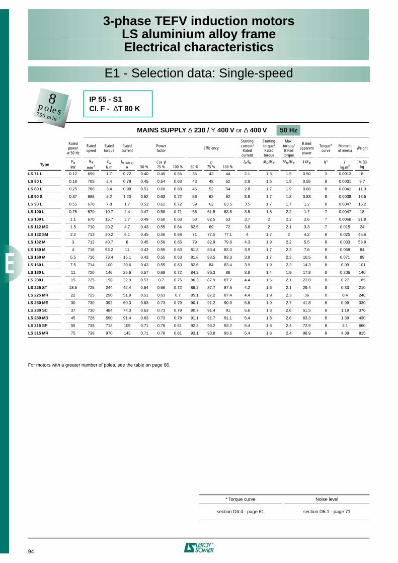
94
3-phase TEFV induction motorsLS aluminium alloy frameElectrical characteristics
For motors with a greater number of poles, see the table on page 66.
MAINS SUPPLY ∆ 230 / Υ 400 V or ∆ 400 V 50 Hz
Ratedpower
at 50 Hz
Rated speed
Rated torque
Rated current
Powerfactor Efficiency
Startingcurrent/Rated
current
Startingtorque/Ratedtorque
Max.torque/Ratedtorque
Rated apparentpower
Torque*curve
Moment of inertia Weight
TypePNkW
NN
min-1CN
N.mIN (400V)
A 50 %Cos ϕ75 % 100 % 50 %
η75 % 100 %
ID/IN MD/MN MM/MN kVAN N° Jkg.m2
IM B3kg
LS 71 L 0.12 650 1.7 0.72 0.40 0.45 0.55 36 42 44 2.1 1.3 1.5 0.50 3 0.0013 8
LS 80 L 0.18 705 2.4 0.79 0.45 0.54 0.63 43 48 52 2.9 1.5 1.9 0.55 8 0.0031 9.7
LS 80 L 0.25 700 3.4 0.98 0.51 0.60 0.68 45 52 54 2.8 1.7 1.9 0.68 8 0.0041 11.3
LS 90 S 0.37 685 5.2 1.20 0.52 0.63 0.72 56 62 62 3.8 1.7 1.8 0.83 8 0.0038 13.5
LS 90 L 0.55 670 7.8 1.7 0.52 0.61 0.72 59 62 63.5 3.5 1.7 1.7 1.2 8 0.0047 15.2
LS 100 L 0.75 670 10.7 2.4 0.47 0.58 0.71 55 61.5 63.5 3.5 1.8 2.2 1.7 7 0.0047 18
LS 100 L 1.1 670 15.7 3.7 0.49 0.60 0.68 58 62.5 63 3.7 2 2.2 2.6 7 0.0068 21.8
LS 112 MG 1.5 710 20.2 4.7 0.43 0.55 0.64 62.5 69 72 3.8 2 2.1 3.3 7 0.015 24
LS 132 SM 2.2 713 30.2 6.1 0.45 0.56 0.68 71 77.5 77.1 4 1.7 2 4.2 8 0.025 45.6
LS 132 M 3 712 40.7 8 0.45 0.56 0.65 79 82.9 79.8 4.3 1.9 2.2 5.5 8 0.033 53.9
LS 160 M 4 718 53.2 11 0.43 0.55 0.63 81.3 83.4 83.3 3.9 1.7 2.3 7.6 8 0.068 84
LS 160 M 5.5 716 73.4 15.1 0.43 0.55 0.63 81.8 83.5 83.3 3.9 1.7 2.3 10.5 8 0.071 89
LS 160 L 7.5 714 100 20.6 0.43 0.55 0.63 82.6 84 83.4 3.9 1.9 2.3 14.3 8 0.09 101
LS 180 L 11 720 146 25.6 0.57 0.68 0.72 84.2 86.3 86 3.8 1.4 1.9 17.8 8 0.205 140
LS 200 L 15 725 198 32.9 0.57 0.7 0.75 86.3 87.9 87.7 4.4 1.6 2.1 22.8 8 0.27 185
LS 225 ST 18.5 725 244 42.4 0.54 0.66 0.72 86.2 87.7 87.5 4.2 1.6 2.1 29.4 8 0.33 210
LS 225 MR 22 725 290 51.9 0.51 0.63 0.7 85.1 87.2 87.4 4.4 1.9 2.3 36 8 0.4 240
LS 250 ME 30 730 392 60.3 0.63 0.73 0.79 90.1 91.2 90.9 5.8 1.9 2.7 41.8 8 0.99 330
LS 280 SC 37 730 484 74.3 0.63 0.73 0.79 90.7 91.4 91 5.6 1.8 2.6 51.5 8 1.19 370
LS 280 MD 45 728 590 91.4 0.63 0.73 0.78 91.1 91.7 91.1 5.4 1.8 2.6 63.3 8 1.39 430
LS 315 SP 55 738 712 105 0.71 0.78 0.81 92.2 93.2 93.2 5.4 1.8 2.4 72.9 8 3.1 660
LS 315 MR 75 738 970 143 0.71 0.78 0.81 93.1 93.8 93.6 5.4 1.8 2.4 98.9 8 4.38 815
* Torque curve Noise level
section D4.4 - page 61 section D6.1 - page 71
E1 - Selection data: Single-speed
IP 55 - S1Cl. F - ∆T 80 K
8poles750 min-1
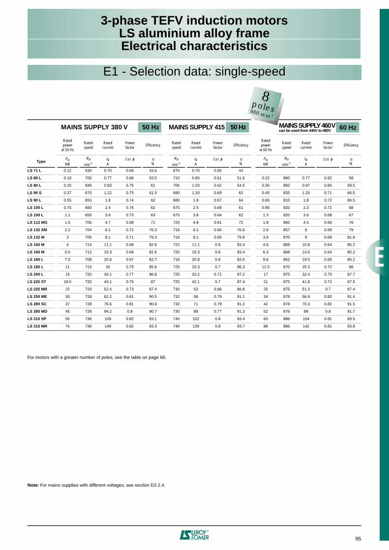
95
3-phase TEFV induction motorsLS aluminium alloy frameElectrical characteristics
E1 - Selection data: single-speed
For motors with a greater number of poles, see the table on page 66.
Note: For mains supplies with different voltages, see section D2.2.4.
MAINS SUPPLY 380 V 50 Hz MAINS SUPPLY 415 50 Hz MAINS SUPPLY 460 V can be used from 440V to 480V
Ratedpower
at 50 Hz
Rated speed
Rated current
Powerfactor Efficiency Rated
speedRated
currentPowerfactor Efficiency
Ratedpower
at 60 Hz
Rated speed
Rated current
Powerfactor Efficiency
TypePNkW
NN
min-1IN A
Cos ϕ η%
NN
min-1IN A
Cos ϕ η%
PNkW
NN
min-1IN A
Cos ϕ η%
LS 71 L 0.12 630 0.70 0.60 43.6 670 0.70 0.50 44
LS 80 L 0.18 700 0.77 0.66 53.5 710 0.80 0.61 51.6 0.22 860 0.77 0.62 58
LS 80 L 0.25 695 0.83 0.75 61 705 1.03 0.62 54.5 0.30 850 0.97 0.65 59.5
LS 90 S 0.37 670 1.22 0.75 61.5 690 1.20 0.69 62 0.45 835 1.20 0.71 66.5
LS 90 L 0.55 655 1.8 0.74 62 680 1.8 0.67 64 0.66 810 1.8 0.72 66.5
LS 100 L 0.75 660 2.4 0.76 62 675 2.5 0.69 61 0.90 820 2.3 0.72 68
LS 100 L 1.1 655 3.6 0.73 63 675 3.8 0.64 62 1.3 820 3.6 0.68 67
LS 112 MG 1.5 705 4.7 0.68 71 720 4.8 0.61 72 1.8 860 4.5 0.66 76
LS 132 SM 2.2 704 6.1 0.72 76.3 716 6.1 0.65 76.6 2.6 857 6 0.69 79
LS 132 M 3 705 8.1 0.71 79.3 715 8.1 0.65 79.8 3.6 870 8 0.69 81.8
LS 160 M 4 714 11.1 0.66 82.6 722 11.1 0.6 83.4 4.6 868 10.6 0.64 85.2
LS 160 M 5.5 712 15.3 0.66 82.6 720 15.3 0.6 83.4 6.3 866 14.5 0.64 85.2
LS 160 L 7.5 708 20.6 0.67 82.7 716 20.8 0.6 83.5 8.6 862 19.5 0.65 85.2
LS 180 L 11 715 26 0.75 85.6 725 25.3 0.7 86.3 12.5 870 25.3 0.72 86
LS 200 L 15 720 34.1 0.77 86.8 725 33.2 0.72 87.2 17 875 32.4 0.75 87.7
LS 225 ST 18.5 720 43.1 0.75 87 725 42.1 0.7 87.4 21 875 41.8 0.72 87.5
LS 225 MR 22 720 52.4 0.73 87.4 730 53 0.66 86.8 25 875 51.3 0.7 87.4
LS 250 ME 30 728 62.2 0.81 90.5 732 58 0.79 91.1 34 878 56.9 0.82 91.4
LS 280 SC 37 728 76.6 0.81 90.6 732 71 0.79 91.2 42 878 70.3 0.82 91.5
LS 280 MD 45 726 94.2 0.8 90.7 730 89 0.77 91.3 52 876 89 0.8 91.7
LS 315 SP 55 736 109 0.82 93.1 740 102 0.8 93.4 63 886 104 0.81 93.5
LS 315 MR 75 736 149 0.82 93.3 740 139 0.8 93.7 86 886 142 0.81 93.8
8poles900 min-1
60 Hz
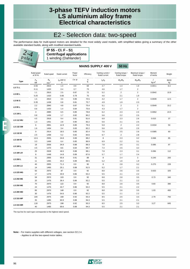
96
3-phase TEFV induction motorsLS aluminium alloy frameElectrical characteristics
The top line for each type corresponds to the highest rated speed.
Note: - For mains supplies with different voltages, see section D2.2.4. - Applies to all the two-speed motor tables.
MAINS SUPPLY 400 V 50 Hz
Rated powerat 50 Hz Rated speed Rated current Power
factor Efficiency Starting current / Rated current
Starting torque / Rated torque
Maximum torque / Rated torque
Momentof inertia Weight
TypePNkW
NN
min-1IN (400 V)
A
Cos ϕ η%
ID/IN MD/MN MM/MN Jkg.m2
IM B3kg
LS 71 L0.55 2810 1.4 0.9 69 4.7 1.4 1.9 0.0011 8.3
0.11 1420 0.4 0.7 73 4.6 1.7 2
LS 80 L1.1 2810 2.5 0.87 72 5.2 2 2 0.0042 10.9
0.25 1420 0.66 0.78 70 4.6 2.1 1.9
LS 90 S1.5 2810 3.6 0.86 70.5 4.2 1.7 2 0.0039 12.5
0.35 1438 0.8 0.81 75.7 4.9 1.9 2.3
LS 90 L2.2 2840 4.8 0.87 75.4 5.1 2 2 0.0049 15.2
0.6 1420 1.4 0.84 75.6 4.3 1.7 2
LS 100 L3 2885 6.5 0.85 78.8 6.2 2.3 2.4 0.0062 24.5
0.8 1436 1.7 0.82 80.2 5.6 2.2 2.5
LS 112 MU4.5 2916 9.4 0.81 81.6 6.8 2.3 2.6 0.015 37
1.3 1451 2.8 0.80 82.2 5.6 2.1 2.5
LS 132 SM6 2891 12.9 0.85 79.3 5.9 2 2.2 0.0334 50
1.6 1454 3.4 0.83 82.2 5.6 1.9 2.5
LS 132 M9 2914 18.5 0.85 82.4 7.6 2.5 2.6 0.0385 60
2.5 1458 5.2 0.82 84.6 6.7 2 2.8
LS 160 M13.5 2935 24.8 0.89 88.2 8 2.3 3.2 0.068 85
3.3 1469 6.4 0.85 86.9 6.9 2.2 3.1
LS 160 L19 2936 34.9 0.88 89.3 7.8 2.5 3.1 0.085 97
4.5 1470 8.6 0.84 89.7 7.4 2.5 3.2
LS 180 LR25 2928 46.5 0.88 88.1 7.8 2.3 3.1 0.096 112
8 1448 14.8 0.89 87.6 5.7 1.7 2.4
LS 200 L31 2955 55.9 0.91 88 8 2.4 3 0.240 200
11 1465 20.2 0.89 88.5 5.2 1.6 1.9
LS 200 LU40 2955 71.3 0.9 90 8 2.8 3.2 0.270 228
14 1465 25.1 0.88 91.5 5.2 1.7 2.1
LS 225 MG50 2970 87 0.9 92 8.8 2.6 3.5 0.633 320
17 1476 30.9 0.86 92.2 5.5 2.1 2.2
LS 250 ME59 2970 103 0.9 92 8.8 2.6 3.5 0.73 340
20 1476 36.4 0.86 92.2 5.5 2.1 2.2
LS 250 ME70 2970 122 0.9 92 8.8 2.6 3.5 0.83 380
24 1476 43.7 0.86 92.2 5.5 2.1 2.2
LS 280 MD85 2970 148 0.9 92 8.8 2.6 3.5 1.03 450
30 1476 54.6 0.86 92.2 5.5 2.1 2.2
LS 315 MP100 2975 168 0.92 93.3 8.5 2.5 3.3 2.79 750
35 1485 60.9 0.88 94.3 5.5 2.1 2.1
LS 315 MR118 2975 198 0.92 93.3 8.5 2.5 3.3 3.27 845
40 1485 69.6 0.88 94.3 5.5 2.1 2.1
E2 - Selection data: two-speed
IP 55 - Cl. F - S1Centrifugal applications1 winding (Dahlander)
2-4poles3000-1500 min -1
The performance data for multi-speed motors are detailed for the most widely used models, with simplified tables giving a summary of the otheravailable standard builds, along with modified standard builds.
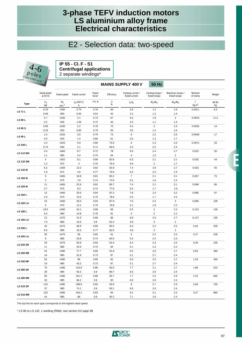
97
3-phase TEFV induction motorsLS aluminium alloy frameElectrical characteristics
The top line for each type corresponds to the highest rated speed.
* LS 80 to LS 132, 1 winding (PAM), see section E2 page 98.
MAINS SUPPLY 400 V 50 Hz
Rated powerat 50 Hz Rated speed Rated current Power
factor Efficiency Starting current / Rated current
Starting torque / Rated torque
Maximum torque / Rated torque
Momentof inertia Weight
TypePNkW
NN
min-1IN (400 V)
A
Cos ϕ η%
ID/IN MD/MN MM/MN Jkg.m2
IM B3kg
LS 71 L0.25 1430 0.75 0.78 66 3.9 1.4 1.9 0.0011 8.3
0.09 960 0.55 0.64 40 2.3 1.2 1.9
LS 80 L0.7 1435 2.1 0.73 67 4.5 1.8 2 0.0024 11.5
0.2 945 1.05 0.72 40 2.5 1.1 1.4
LS 90 S0.85 1430 2.2 0.78 70 5.5 2 2.4 0.0032 14
0.25 930 0.85 0.79 55 3.5 1.2 1.6
LS 90 L1.4 1425 3.5 0.79 73 6 2.2 2.6 0.0049 17
0.5 925 1.4 0.80 61 3.6 1.3 1.7
LS 100 L2.4 1425 5.9 0.80 73.9 6 2.4 2.6 0.0071 25
0.75 940 2.1 0.71 66.8 4.3 2.2 2.3
LS 112 MG3.4 1460 8.7 0.72 78 6.9 2.4 2.7 0.015 30
1.1 965 3.4 0.75 64 4 1.3 2
LS 132 SM4 1452 8.1 0.86 82.8 6.3 2.1 2.1 0.025 44
1.2 972 3 0.76 76.9 4.6 2 1.7
LS 132 M6.3 1459 13.2 0.82 83.9 7.4 2.8 2.7 0.033 55
1.9 974 4.6 0.77 76.9 5.5 2.3 1.9
LS 160 M9 1465 18.8 0.81 85.2 7 2.1 3.1 0.057 75
3 975 7.8 0.74 74.9 5.2 1.6 2.4
LS 160 M11 1465 22.6 0.82 85.7 7.4 2.1 3.1 0.068 85
3.7 975 9.3 0.74 77.8 5.5 1.7 2.6
LS 160 L13 1465 25.6 0.84 87.3 7.8 2.3 3.2 0.085 97
4.3 970 10.5 0.75 78.6 5.5 1.7 2.5
LS 160 LU15 1465 29.3 0.84 87.9 7.5 2.4 3 0.096 109
5 970 12.1 0.76 78.8 5.1 1.8 2.2
LS 180 L18.5 1460 34.1 0.88 89 5.5 2 2.3 0.123 136
6.5 980 14.8 0.78 81 5 2 2.2
LS 180 LU22 1470 41.5 0.86 89 6.8 2.6 2.7 0.147 155
7.5 980 16.6 0.8 81.5 4.8 2 2
LS 200 L25 1475 46.9 0.85 90.5 6.4 2.2 2.5 0.24 200
8.5 985 19.3 0.77 82.5 4.8 2 2
LS 200 LU30 1475 56 0.85 91 6 2.2 2.5 0.27 228
9 985 20.8 0.74 84.5 5.3 2.4 2.3
LS 225 SR34 1475 63.8 0.84 91.6 6.3 2.3 2.6 0.29 235
11 985 25.9 0.73 84 5.1 2.3 2.2
LS 250 ME42 1480 77.7 0.85 91.8 6.5 2.5 2.7 0.83 380
14 985 31.8 0.73 87 5.1 2.7 2.4
LS 250 MF52 1480 96 0.85 92 6.5 2.5 2.7 1.03 450
19 985 43.2 0.73 87 5.1 2.7 2.4
LS 280 SK75 1485 134.6 0.86 93.5 7.7 2.1 2.7 1.89 610
28 985 56.3 0.8 89.7 6.6 2.9 2.4
LS 280 MK90 1485 161.2 0.86 93.7 7.7 2.3 2.9 2.23 665
33 985 66.2 0.8 90 6.9 2.9 2.4
LS 315 SP110 1485 198.9 0.85 93.9 8 2.7 2.9 2.64 750
37 985 74.1 0.8 90.1 6.9 2.9 2.4
LS 315 MR132 1485 244.2 0.83 94 9.2 3.1 3.3 3.27 860
44 985 88 0.8 90.2 7.1 2.9 2.4
IP 55 - Cl. F - S1Centrifugal applications2 separate windings*
4-6poles1500-1000 min -1
E2 - Selection data: two-speed
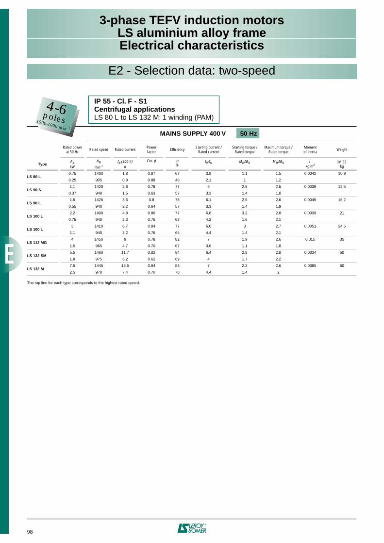
98
3-phase TEFV induction motorsLS aluminium alloy frameElectrical characteristics
The top line for each type corresponds to the highest rated speed.
MAINS SUPPLY 400 V 50 Hz
Rated powerat 50 Hz Rated speed Rated current Power
factor Efficiency Starting current / Rated current
Starting torque / Rated torque
Maximum torque / Rated torque
Momentof inertia Weight
TypePNkW
NN
min-1IN (400 V)
A
Cos ϕ η%
ID/IN MD/MN MM/MN Jkg.m2
IM B3kg
LS 80 L0.75 1400 1.8 0.87 67 3.8 1.1 1.5 0.0042 10.9
0.25 905 0.9 0.88 46 2.1 1 1.2
LS 90 S1.1 1420 2.6 0.79 77 6 2.5 2.5 0.0039 12.5
0.37 940 1.5 0.63 57 3.3 1.4 1.8
LS 90 L1.5 1425 3.6 0.8 78 6.1 2.5 2.6 0.0049 15.2
0.55 940 2.2 0.64 57 3.3 1.4 1.9
LS 100 L2.2 1400 4.8 0.86 77 6.8 3.2 2.8 0.0039 21
0.75 940 2.3 0.75 63 4.2 1.6 2.1
LS 100 L3 1410 6.7 0.84 77 6.6 3 2.7 0.0051 24.5
1.1 940 3.2 0.76 65 4.4 1.4 2.1
LS 112 MG4 1450 9 0.78 82 7 1.9 2.6 0.015 35
1.5 965 4.7 0.70 67 3.6 1.1 1.8
LS 132 SM5.5 1460 11.7 0.82 84 6.4 2.8 2.8 0.0334 50
1.8 975 6.2 0.62 69 4 1.7 2.2
LS 132 M7.5 1445 15.5 0.84 83 7 2.2 2.6 0.0385 60
2.5 970 7.4 0.70 70 4.4 1.4 2
IP 55 - Cl. F - S1Centrifugal applicationsLS 80 L to LS 132 M: 1 winding (PAM)
4-6poles1500-1000 min -1
E2 - Selection data: two-speed

99
3-phase TEFV induction motorsLS aluminium alloy frameElectrical characteristics
The top line for each type corresponds to the highest rated speed.
MAINS SUPPLY 400 V 50 Hz
Rated powerat 50 Hz Rated speed Rated current Power
factor Efficiency Starting current / Rated current
Starting torque / Rated torque
Maximum torque / Rated torque
Momentof inertia Weight
TypePNkW
NN
min-1IN (400 V)
A
Cos ϕ η%
ID/IN MD/MN MM/MN Jkg.m2
IM B3kg
LS 71 L0.25 1430 0.8 0.7 65 3.5 1.3 2 0.00085 7.30.06 640 0.4 0.6 98 1.5 1.1 1.3
LS 71 L0.37 1430 1.15 0.8 60 4 1.4 2.1 0.0011 8.30.07 670 0.5 0.7 30 2.1 1.2 1.4
LS 80 L0.55 1435 1.6 0.71 69 4.8 2.6 2.4 0.0018 9.30.09 715 0.6 0.48 46 2.3 2.8 2.4
LS 80 L0.75 1425 2.3 0.72 65 4.8 2.3 2.3 0.0024 10.9
0.12 710 0.9 0.52 41 2.3 2.7 2.3
LS 90 S1.1 1441 3 0.78 67.5 4.1 1.1 1.5 0.0032 11.5
0.18 724 1.1 0.53 43.5 2.9 1.5 2.3
LS 90 L1.5 1459 4.2 0.70 73.4 5.5 1.9 2.5 0.0049 15.2
0.25 732 1.6 0.44 50.5 3.1 2.8 3.6
LS 100 L2.2 1446 5.5 0.78 73.6 5.2 1.7 2.1 0.0051 21
0.37 726 2 0.50 53.7 3.2 2.4 3
LS 100 L3 1435 7.4 0.79 75 5.5 1.6 2.3 0.0071 24.4
0.55 715 2.6 0.52 58 2.7 2.1 2.1
LS 112 MU4 1455 8.7 0.80 82.9 6.7 2.1 2.6 0.015 37
0.75 730 3.5 0.47 66 3.6 2.9 3.3
LS 132 SM5.5 1452 11 0.87 83.3 6.4 2 2.3 0.0334 55
1.1 726 3.2 0.63 78 3.7 2 1.9
LS 132 M7.5 1449 14.7 0.88 83.7 6.3 2 2.3 0.0385 60
1.5 727 4.3 0.63 79 4.1 2 2.2
LS 160 M9 1462 17.9 0.84 86.4 6.4 1.9 2.8 0.057 75
2.2 724 6.3 0.64 79.2 3.7 1.4 2.2
LS 160 M11 1464 21.6 0.84 87.5 7.2 2.1 3 0.068 85
2.8 724 7.8 0.64 80.9 3.7 1.5 2.2
LS 160 L13 1464 25.8 0.83 87.5 6.9 2.1 2.9 0.074 89
3.3 722 9.4 0.63 80.5 3.7 1.5 2.1
LS 160 L15 1462 29.5 0.84 87.5 6.8 2.3 2.8 0.085 97
3.8 722 10.6 0.64 80.5 3.4 1.4 2
LS 180 LR18.5 1462 36.6 0.83 87.9 7.2 2.4 3 0.096 112
4.8 722 13.3 0.64 81.5 3.6 1.4 2
LS 180 LU22 1464 40.9 0.87 89.2 6 2.1 2.4 0.135 150
5.3 730 13.2 0.68 85.5 3.6 1.8 1.7
LS 200 LT24 1468 45.2 0.85 90.1 7.1 2.8 2.8 0.151 165
6 730 15.4 0.65 86.6 3.7 2.1 1.8
LS 200 L30 1475 55.8 0.86 90.3 6.1 2.1 2.4 0.240 200
7 735 18.6 0.63 86 3.8 1.9 1.8
LS 225 SR37 1475 69.2 0.85 90.8 6.8 2.3 2.7 0.290 235
8.5 735 21.8 0.64 88 4 2.1 1.8
LS 225 MG45 1482 83.1 0.85 92 7 2.3 3 0.633 320
11 738 26.3 0.66 91.3 4 1.8 1.8
LS 250 ME55 1484 100.8 0.85 92.7 7.7 2.6 3.4 0.83 380
14 738 33.1 0.66 92.4 4 1.8 1.9
LS 250 MF65 1484 118.7 0.85 93 7.7 2.6 3.4 0.9 430
16 738 37.7 0.66 92.8 4 1.8 1.9
LS 280 SD75 1484 136.9 0.85 93 7.7 2.6 3.4 1.03 450
19 738 45.5 0.65 92.8 3.9 1.7 1.8
LS 280 MK90 1490 163.3 0.85 93.6 8.3 2.8 3.1 2.32 655
23 742 56.8 0.64 91.3 4.8 2.3 1.9
LS 315 SP110 1490 199.1 0.85 93.8 8.3 2.8 2.9 2.79 750
29 742 71.6 0.64 91.3 4.8 2.3 1.9
LS 315 MR132 1490 238.5 0.85 94 8.3 2.8 2.9 3.27 845
35 742 86.3 0.64 91.5 4.9 2.2 2
LS 315 MR160 1485 288.4 0.85 94.2 8.3 2.8 2.9 3.27 860
42 740 101.7 0.65 91.7 5 2.2 2
IP 55 - Cl. F - S1Centrifugal applications1 winding (Dahlander)
4-8poles1500-750 min -1
E2 - Selection data: two-speed
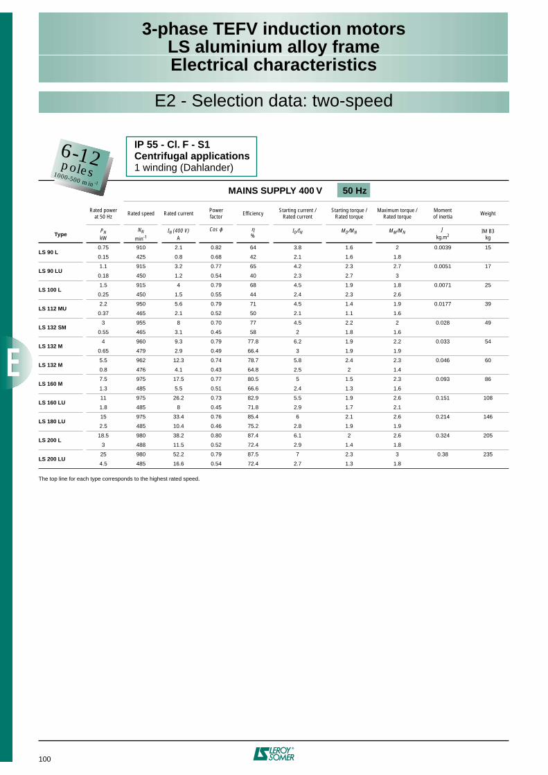
100
3-phase TEFV induction motorsLS aluminium alloy frameElectrical characteristics
The top line for each type corresponds to the highest rated speed.
MAINS SUPPLY 400 V 50 Hz
Rated powerat 50 Hz Rated speed Rated current Power
factor Efficiency Starting current / Rated current
Starting torque / Rated torque
Maximum torque / Rated torque
Momentof inertia Weight
TypePNkW
NN
min-1IN (400 V)
A
Cos ϕ η%
ID/IN MD/MN MM/MN Jkg.m2
IM B3kg
LS 90 L0.75 910 2.1 0.82 64 3.8 1.6 2 0.0039 15
0.15 425 0.8 0.68 42 2.1 1.6 1.8
LS 90 LU1.1 915 3.2 0.77 65 4.2 2.3 2.7 0.0051 17
0.18 450 1.2 0.54 40 2.3 2.7 3
LS 100 L1.5 915 4 0.79 68 4.5 1.9 1.8 0.0071 25
0.25 450 1.5 0.55 44 2.4 2.3 2.6
LS 112 MU2.2 950 5.6 0.79 71 4.5 1.4 1.9 0.0177 39
0.37 465 2.1 0.52 50 2.1 1.1 1.6
LS 132 SM3 955 8 0.70 77 4.5 2.2 2 0.028 49
0.55 465 3.1 0.45 58 2 1.8 1.6
LS 132 M4 960 9.3 0.79 77.8 6.2 1.9 2.2 0.033 54
0.65 479 2.9 0.49 66.4 3 1.9 1.9
LS 132 M5.5 962 12.3 0.74 78.7 5.8 2.4 2.3 0.046 60
0.8 476 4.1 0.43 64.8 2.5 2 1.4
LS 160 M7.5 975 17.5 0.77 80.5 5 1.5 2.3 0.093 86
1.3 485 5.5 0.51 66.6 2.4 1.3 1.6
LS 160 LU11 975 26.2 0.73 82.9 5.5 1.9 2.6 0.151 108
1.8 485 8 0.45 71.8 2.9 1.7 2.1
LS 180 LU15 975 33.4 0.76 85.4 6 2.1 2.6 0.214 146
2.5 485 10.4 0.46 75.2 2.8 1.9 1.9
LS 200 L18.5 980 38.2 0.80 87.4 6.1 2 2.6 0.324 205
3 488 11.5 0.52 72.4 2.9 1.4 1.8
LS 200 LU25 980 52.2 0.79 87.5 7 2.3 3 0.38 235
4.5 485 16.6 0.54 72.4 2.7 1.3 1.8
E2 - Selection data: two-speed
6-12poles1000-500 min -1
IP 55 - Cl. F - S1Centrifugal applications1 winding (Dahlander)
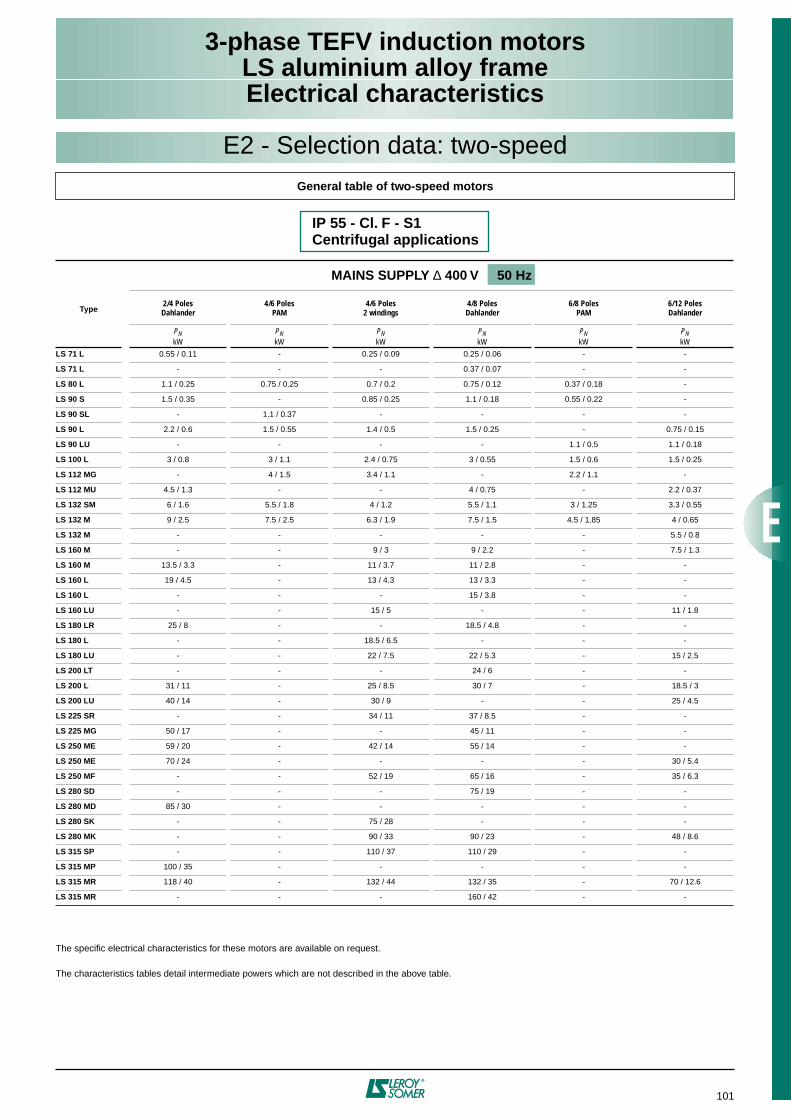
101
3-phase TEFV induction motorsLS aluminium alloy frameElectrical characteristics
E2 - Selection data: two-speed
IP 55 - Cl. F - S1Centrifugal applications
General table of two-speed motors
The specific electrical characteristics for these motors are available on request.
The characteristics tables detail intermediate powers which are not described in the above table.
Type
MAINS SUPPLY ∆ 400 V 50 Hz
2/4 PolesDahlander
4/6 PolesPAM
4/6 Poles2 windings
4/8 PolesDahlander
6/8 PolesPAM
6/12 PolesDahlander
PNkW
PNkW
PNkW
PNkW
PNkW
PNkW
LS 71 L 0.55 / 0.11 - 0.25 / 0.09 0.25 / 0.06 - -
LS 71 L - - - 0.37 / 0.07 - -
LS 80 L 1.1 / 0.25 0.75 / 0.25 0.7 / 0.2 0.75 / 0.12 0.37 / 0.18 -
LS 90 S 1.5 / 0.35 - 0.85 / 0.25 1.1 / 0.18 0.55 / 0.22 -
LS 90 SL - 1.1 / 0.37 - - - -
LS 90 L 2.2 / 0.6 1.5 / 0.55 1.4 / 0.5 1.5 / 0.25 - 0.75 / 0.15
LS 90 LU - - - - 1.1 / 0.5 1.1 / 0.18
LS 100 L 3 / 0.8 3 / 1.1 2.4 / 0.75 3 / 0.55 1.5 / 0.6 1.5 / 0.25
LS 112 MG - 4 / 1.5 3.4 / 1.1 - 2.2 / 1.1 -
LS 112 MU 4.5 / 1.3 - - 4 / 0.75 - 2.2 / 0.37
LS 132 SM 6 / 1.6 5.5 / 1.8 4 / 1.2 5.5 / 1.1 3 / 1.25 3.3 / 0.55
LS 132 M 9 / 2.5 7.5 / 2.5 6.3 / 1.9 7.5 / 1.5 4.5 / 1.85 4 / 0.65
LS 132 M - - - - - 5.5 / 0.8
LS 160 M - - 9 / 3 9 / 2.2 - 7.5 / 1.3
LS 160 M 13.5 / 3.3 - 11 / 3.7 11 / 2.8 - -
LS 160 L 19 / 4.5 - 13 / 4.3 13 / 3.3 - -
LS 160 L - - - 15 / 3.8 - -
LS 160 LU - - 15 / 5 - - 11 / 1.8
LS 180 LR 25 / 8 - - 18.5 / 4.8 - -
LS 180 L - - 18.5 / 6.5 - - -
LS 180 LU - - 22 / 7.5 22 / 5.3 - 15 / 2.5
LS 200 LT - - - 24 / 6 - -
LS 200 L 31 / 11 - 25 / 8.5 30 / 7 - 18.5 / 3
LS 200 LU 40 / 14 - 30 / 9 - - 25 / 4.5
LS 225 SR - - 34 / 11 37 / 8.5 - -
LS 225 MG 50 / 17 - - 45 / 11 - -
LS 250 ME 59 / 20 - 42 / 14 55 / 14 - -
LS 250 ME 70 / 24 - - - - 30 / 5.4
LS 250 MF - - 52 / 19 65 / 16 - 35 / 6.3
LS 280 SD - - - 75 / 19 - -
LS 280 MD 85 / 30 - - - - -
LS 280 SK - - 75 / 28 - - -
LS 280 MK - - 90 / 33 90 / 23 - 48 / 8.6
LS 315 SP - - 110 / 37 110 / 29 - -
LS 315 MP 100 / 35 - - - - -
LS 315 MR 118 / 40 - 132 / 44 132 / 35 - 70 / 12.6
LS 315 MR - - - 160 / 42 - -
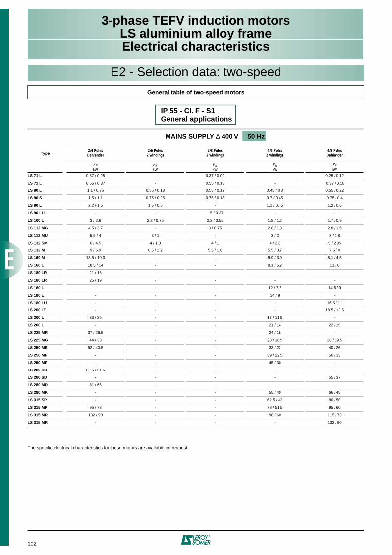
102
3-phase TEFV induction motorsLS aluminium alloy frameElectrical characteristics
IP 55 - Cl. F - S1General applications
General table of two-speed motors
The specific electrical characteristics for these motors are available on request.
Type
MAINS SUPPLY ∆ 400 V 50 Hz
2/4 PolesDahlander
2/6 Poles2 windings
2/8 Poles2 windings
4/6 Poles2 windings
4/8 PolesDahlander
PNkW
PNkW
PNkW
PNkW
PNkW
LS 71 L 0.37 / 0.25 - 0.37 / 0.09 - 0.25 / 0.12
LS 71 L 0.55 / 0.37 - 0.55 / 0.18 - 0.37 / 0.18
LS 80 L 1.1 / 0.75 0.55 / 0.18 0.55 / 0.12 0.45 / 0.3 0.55 / 0.22
LS 90 S 1.5 / 1.1 0.75 / 0.25 0.75 / 0.18 0.7 / 0.45 0.75 / 0.4
LS 90 L 2.2 / 1.5 1.5 / 0.5 - 1.1 / 0.75 1.2 / 0.6
LS 90 LU - - 1.5 / 0.37 - -
LS 100 L 3 / 2.6 2.2 / 0.75 2.2 / 0.55 1.8 / 1.2 1.7 / 0.9
LS 112 MG 4.5 / 3.7 - 3 / 0.75 2.8 / 1.8 2.8 / 1.5
LS 112 MU 5.5 / 4 3 / 1 - 3 / 2 3 / 1.8
LS 132 SM 6 / 4.5 4 / 1.3 4 / 1 4 / 2.8 5 / 2.85
LS 132 M 9 / 6.9 6.5 / 2.2 5.5 / 1.6 5.5 / 3.7 7.6 / 4
LS 160 M 13.5 / 10.3 - - 5.9 / 3.9 8.1 / 4.5
LS 160 L 18.5 / 14 - - 8.1 / 5.2 11 / 6
LS 180 LR 21 / 16 - - - -
LS 180 LR 25 / 19 - - - -
LS 180 L - - - 12 / 7.7 14.5 / 9
LS 180 L - - - 14 / 9 -
LS 180 LU - - - - 16.5 / 11
LS 200 LT - - - - 18.5 / 12.5
LS 200 L 33 / 25 - - 17 / 11.5 -
LS 200 L - - - 21 / 14 22 / 15
LS 225 MR 37 / 26.5 - - 24 / 16 -
LS 225 MG 44 / 33 - - 28 / 18.5 28 / 19.5
LS 250 ME 52 / 40.5 - - 33 / 22 40 / 26
LS 250 MF - - - 39 / 22.5 50 / 33
LS 250 MF - - - 45 / 30 -
LS 280 SC 62.5 / 51.5 - - - -
LS 280 SD - - - - 55 / 37
LS 280 MD 81 / 66 - - - -
LS 280 MK - - - 55 / 40 66 / 45
LS 315 SP - - - 62.5 / 42 80 / 50
LS 315 MP 95 / 78 - - 78 / 51.5 95 / 60
LS 315 MR 132 / 90 - - 90 / 60 115 / 73
LS 315 MR - - - - 132 / 90
E2 - Selection data: two-speed
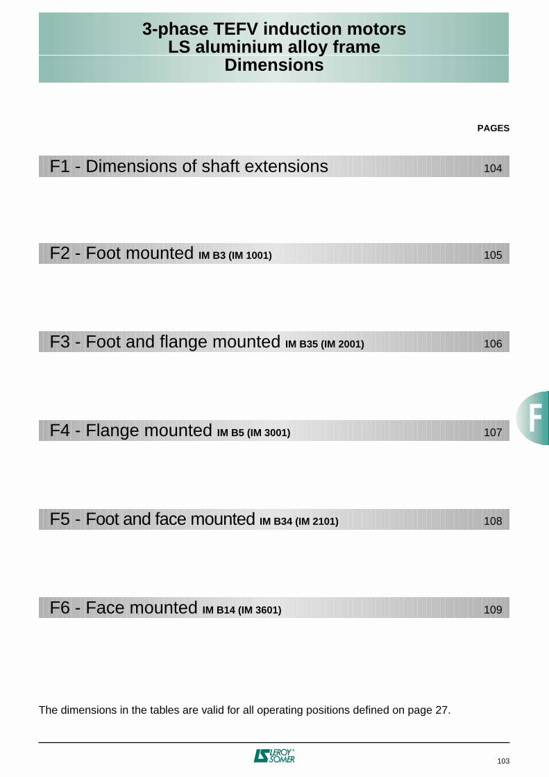
3-phase TEFV induction motorsLS aluminium alloy frame
Dimensions
103
PAGES
The dimensions in the tables are valid for all operating positions defined on page 27.
F1 - Dimensions of shaft extensions 104
F2 - Foot mounted IM B3 (IM 1001) 105
F3 - Foot and flange mounted IM B35 (IM 2001) 106
F4 - Flange mounted IM B5 (IM 3001) 107
F5 - Foot and face mounted IM B34 (IM 2101) 108
F6 - Face mounted IM B14 (IM 3601) 109
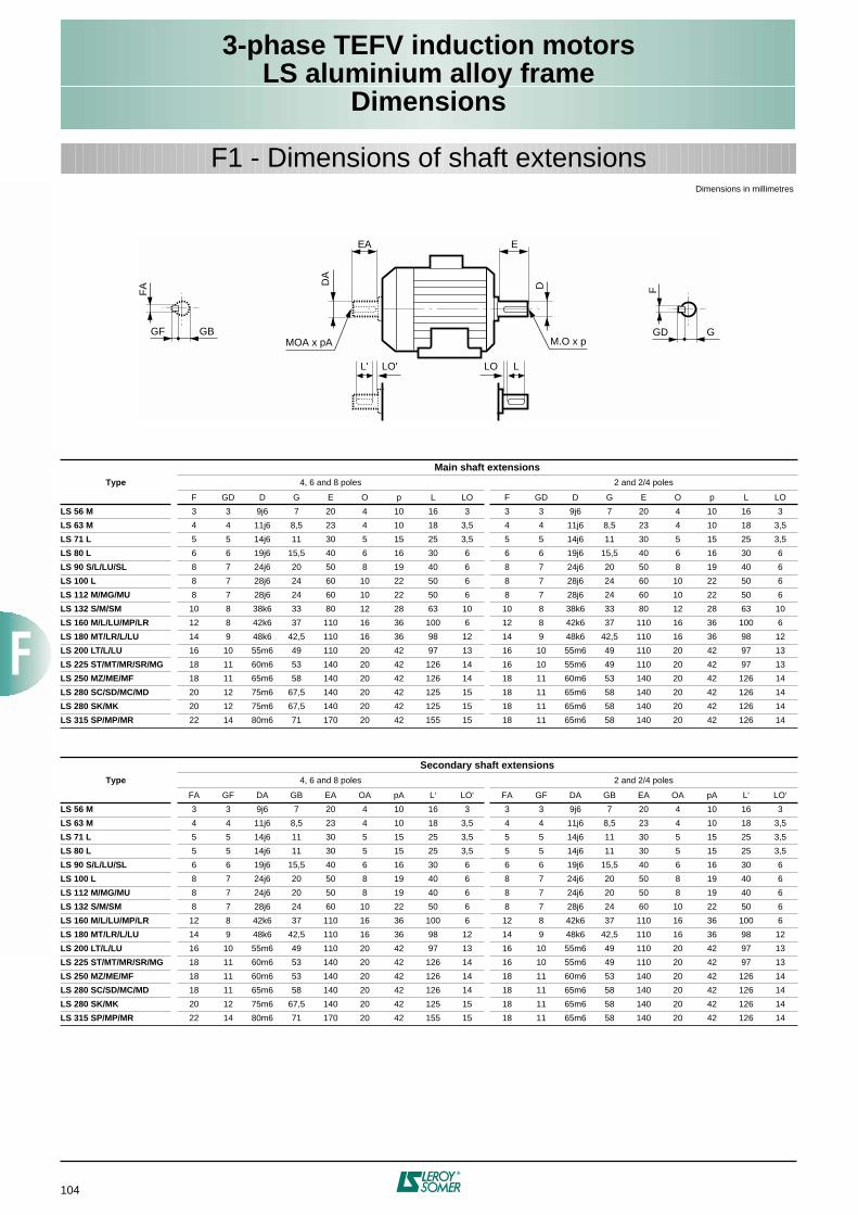
104
3-phase TEFV induction motorsLS aluminium alloy frame
Dimensions
F1 - Dimensions of shaft extensions
Type
Main shaft extensions
4, 6 and 8 poles 2 and 2/4 poles
F GD D G E O p L LO F GD D G E O p L LO
LS 56 M
3 3 9j6 7 20 4 10 16 3 3 3 9j6 7 20 4 10 16 3
LS 63 M
4 4 11j6 8,5 23 4 10 18 3,5 4 4 11j6 8,5 23 4 10 18 3,5
LS 71 L
5 5 14j6 11 30 5 15 25 3,5 5 5 14j6 11 30 5 15 25 3,5
LS 80 L
6 6 19j6 15,5 40 6 16 30 6 6 6 19j6 15,5 40 6 16 30 6
LS 90 S/L/LU/SL
8 7 24j6 20 50 8 19 40 6 8 7 24j6 20 50 8 19 40 6
LS 100 L
8 7 28j6 24 60 10 22 50 6 8 7 28j6 24 60 10 22 50 6
LS 112 M/MG/MU
8 7 28j6 24 60 10 22 50 6 8 7 28j6 24 60 10 22 50 6
LS 132 S/M/SM
10 8 38k6 33 80 12 28 63 10 10 8 38k6 33 80 12 28 63 10
LS 160 M/L/LU/MP/LR
12 8 42k6 37 110 16 36 100 6 12 8 42k6 37 110 16 36 100 6
LS 180 MT/LR/L/LU
14 9 48k6 42,5 110 16 36 98 12 14 9 48k6 42,5 110 16 36 98 12
LS 200 LT/L/LU
16 10 55m6 49 110 20 42 97 13 16 10 55m6 49 110 20 42 97 13
LS 225 ST/MT/MR/SR/MG
18 11 60m6 53 140 20 42 126 14 16 10 55m6 49 110 20 42 97 13
LS 250 MZ/ME/MF
18 11 65m6 58 140 20 42 126 14 18 11 60m6 53 140 20 42 126 14
LS 280 SC/SD/MC/MD
20 12 75m6 67,5 140 20 42 125 15 18 11 65m6 58 140 20 42 126 14
LS 280 SK/MK
20 12 75m6 67,5 140 20 42 125 15 18 11 65m6 58 140 20 42 126 14
LS 315 SP/MP/MR
22 14 80m6 71 170 20 42 155 15 18 11 65m6 58 140 20 42 126 14
Type
Secondary shaft extensions
4, 6 and 8 poles 2 and 2/4 poles
FA GF DA GB EA OA pA L‘ LO‘ FA GF DA GB EA OA pA L‘ LO‘
LS 56 M
3 3 9j6 7 20 4 10 16 3 3 3 9j6 7 20 4 10 16 3
LS 63 M
4 4 11j6 8,5 23 4 10 18 3,5 4 4 11j6 8,5 23 4 10 18 3,5
LS 71 L
5 5 14j6 11 30 5 15 25 3,5 5 5 14j6 11 30 5 15 25 3,5
LS 80 L
5 5 14j6 11 30 5 15 25 3,5 5 5 14j6 11 30 5 15 25 3,5
LS 90 S/L/LU/SL
6 6 19j6 15,5 40 6 16 30 6 6 6 19j6 15,5 40 6 16 30 6
LS 100 L
8 7 24j6 20 50 8 19 40 6 8 7 24j6 20 50 8 19 40 6
LS 112 M/MG/MU
8 7 24j6 20 50 8 19 40 6 8 7 24j6 20 50 8 19 40 6
LS 132 S/M/SM
8 7 28j6 24 60 10 22 50 6 8 7 28j6 24 60 10 22 50 6
LS 160 M/L/LU/MP/LR
12 8 42k6 37 110 16 36 100 6 12 8 42k6 37 110 16 36 100 6
LS 180 MT/LR/L/LU
14 9 48k6 42,5 110 16 36 98 12 14 9 48k6 42,5 110 16 36 98 12
LS 200 LT/L/LU
16 10 55m6 49 110 20 42 97 13 16 10 55m6 49 110 20 42 97 13
LS 225 ST/MT/MR/SR/MG
18 11 60m6 53 140 20 42 126 14 16 10 55m6 49 110 20 42 97 13
LS 250 MZ/ME/MF
18 11 60m6 53 140 20 42 126 14 18 11 60m6 53 140 20 42 126 14
LS 280 SC/SD/MC/MD
18 11 65m6 58 140 20 42 126 14 18 11 65m6 58 140 20 42 126 14
LS 280 SK/MK
20 12 75m6 67,5 140 20 42 125 15 18 11 65m6 58 140 20 42 126 14
LS 315 SP/MP/MR
22 14 80m6 71 170 20 42 155 15 18 11 65m6 58 140 20 42 126 14
E
D
M.O x p
EA
DA
L' LO'
MOA x pA
F
GD G
FA
GF GB
LLO
Dimensions in millimetres
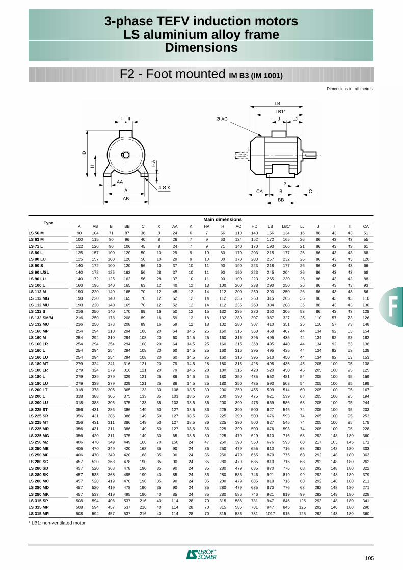
105
3-phase TEFV induction motorsLS aluminium alloy frame
Dimensions
F2 - Foot mounted
IM B3 (IM 1001)
* LB1: non-ventilated motor
Type
Main dimensions
A AB B BB C X AA K HA H AC HD LB LB1* LJ J I II CA
LS 56 M
90 104 71 87 36 8 24 6 7 56 110 140 156 134 16 86 43 43 51
LS 63 M
100 115 80 96 40 8 26 7 9 63 124 152 172 165 26 86 43 43 55
LS 71 L
112 126 90 106 45 8 24 7 9 71 140 170 193 166 21 86 43 43 61
LS 80 L
125 157 100 120 50 10 29 9 10 80 170 203 215 177 26 86 43 43 68
LS 80 LU
125 157 100 120 50 10 29 9 10 80 170 203 267 232 26 86 43 43 120
LS 90 S
140 172 100 120 56 10 37 10 11 90 190 223 218 177 26 86 43 43 66
LS 90 L/SL
140 172 125 162 56 28 37 10 11 90 190 223 245 204 26 86 43 43 68
LS 90 LU
140 172 125 162 56 28 37 10 11 90 190 223 265 230 26 86 43 43 88
LS 100 L
160 196 140 165 63 12 40 12 13 100 200 238 290 250 26 86 43 43 93
LS 112 M
190 220 140 165 70 12 45 12 14 112 200 250 290 250 26 86 43 43 86
LS 112 MG
190 220 140 165 70 12 52 12 14 112 235 260 315 265 36 86 43 43 110
LS 112 MU
190 220 140 165 70 12 52 12 14 112 235 260 334 288 36 86 43 43 130
LS 132 S
216 250 140 170 89 16 50 12 15 132 235 280 350 306 53 86 43 43 128
LS 132 SM/M
216 250 178 208 89 16 59 12 18 132 280 307 387 327 25 110 57 73 126
LS 132 MU
216 250 178 208 89 16 59 12 18 132 280 307 410 351 25 110 57 73 148
LS 160 MP
254 294 210 294 108 20 64 14,5 25 160 315 368 468 407 44 134 92 63 154
LS 160 M
254 294 210 294 108 20 60 14,5 25 160 316 395 495 435 44 134 92 63 182
LS 160 LR
254 294 254 294 108 20 64 14,5 25 160 315 368 495 440 44 134 92 63 138
LS 160 L
254 294 254 294 108 20 60 14,5 25 160 316 395 495 435 44 134 92 63 138
LS 160 LU
254 294 254 294 108 20 60 14,5 25 160 316 395 510 450 44 134 92 63 153
LS 180 MT
279 324 241 316 121 20 79 14,5 28 180 316 428 495 435 45 205 100 95 138
LS 180 LR
279 324 279 316 121 20 79 14,5 28 180 316 428 520 450 45 205 100 95 125
LS 180 L
279 339 279 329 121 25 86 14,5 25 180 350 435 552 481 54 205 100 95 159
LS 180 LU
279 339 279 329 121 25 86 14,5 25 180 350 435 593 508 54 205 100 95 199
LS 200 LT
318 378 305 365 133 30 108 18,5 30 200 350 455 599 514 60 205 100 95 167
LS 200 L
318 388 305 375 133 35 103 18,5 36 200 390 475 621 539 68 205 100 95 194
LS 200 LU
318 388 305 375 133 35 103 18,5 36 200 390 475 669 586 68 205 100 95 244
LS 225 ST
356 431 286 386 149 50 127 18,5 36 225 390 500 627 545 74 205 100 95 203
LS 225 SR
356 431 286 386 149 50 127 18,5 36 225 390 500 676 593 74 205 100 95 253
LS 225 MT
356 431 311 386 149 50 127 18,5 36 225 390 500 627 545 74 205 100 95 178
LS 225 MR
356 431 311 386 149 50 127 18,5 36 225 390 500 676 593 74 205 100 95 228
LS 225 MG
356 420 311 375 149 30 65 18,5 30 225 479 629 810 716 68 292 148 180 360
LS 250 MZ
406 470 349 449 168 70 150 24 47 250 390 550 676 593 68 217 103 145 171
LS 250 ME
406 470 349 420 168 35 90 24 36 250 479 655 810 716 68 292 148 180 303
LS 250 MF
406 470 349 420 168 35 90 24 36 250 479 655 870 776 68 292 148 180 363
LS 280 SC
457 520 368 478 190 35 90 24 35 280 479 685 810 716 68 292 148 180 262
LS 280 SD
457 520 368 478 190 35 90 24 35 280 479 685 870 776 68 292 148 180 322
LS 280 SK
457 533 368 495 190 40 85 24 35 280 586 746 921 819 99 292 148 180 379
LS 280 MC
457 520 419 478 190 35 90 24 35 280 479 685 810 716 68 292 148 180 211
LS 280 MD
457 520 419 478 190 35 90 24 35 280 479 685 870 776 68 292 148 180 271
LS 280 MK
457 533 419 495 190 40 85 24 35 280 586 746 921 819 99 292 148 180 328
LS 315 SP
508 594 406 537 216 40 114 28 70 315 586 781 947 845 125 292 148 180 341
LS 315 MP
508 594 457 537 216 40 114 28 70 315 586 781 947 845 125 292 148 180 290
LS 315 MR
508 594 457 537 216 40 114 28 70 315 586 781 1017 915 125 292 148 180 360
J LJ
LB
LB1*
Ø AC
x
B C
BB
CAA
HD
H HA
AB
AA4 Ø K
I II
Dimensions in millimetres
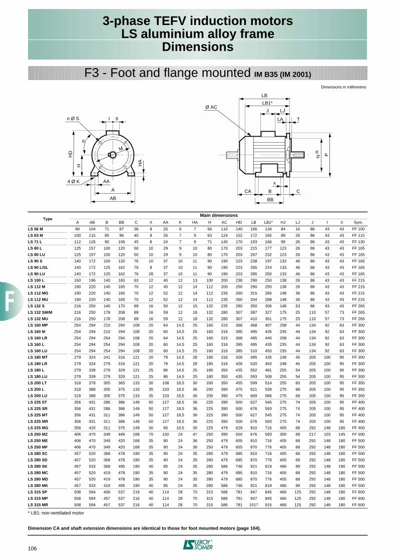
106
3-phase TEFV induction motorsLS aluminium alloy frame
Dimensions
F3 - Foot and flange mounted
IM B35 (IM 2001)
* LB1: non-ventilated motor
Dimension CA and shaft extension dimensions are identical to those for foot mounted motors (page 104).
Type
Main dimensions
A AB B BB C X AA K HA H AC HD LB LB1* HJ LJ J I II Sym.
LS 56 M
90 104 71 87 36 8 25 6 7 56 110 140 156 134 84 16 86 43 43 FF 100
LS 63 M
100 115 80 96 40 8 26 7 9 63 124 152 172 165 89 26 86 43 43 FF 115
LS 71 L
112 126 90 106 45 8 24 7 9 71 140 170 193 166 99 26 86 43 43 FF 130
LS 80 L
125 157 100 120 50 10 29 9 10 80 170 203 215 177 123 26 86 43 43 FF 165
LS 80 LU
125 157 100 120 50 10 29 9 10 80 170 203 267 232 123 26 86 43 43 FF 165
LS 90 S
140 172 100 120 76 10 37 10 11 90 190 223 238 197 133 46 86 43 43 FF 165
LS 90 L/SL
140 172 125 162 76 8 37 10 11 90 190 223 265 224 133 46 86 43 43 FF 165
LS 90 LU
140 172 125 162 76 28 37 10 11 90 190 223 285 250 133 46 86 43 43 FF 165
LS 100 L
160 196 140 165 63 12 40 12 13 100 200 238 290 250 138 26 86 43 43 FF 215
LS 112 M
190 220 140 165 70 12 45 12 14 112 200 250 290 250 138 26 86 43 43 FF 215
LS 112 MG
190 220 140 165 70 12 52 12 14 112 235 260 315 265 148 36 86 43 43 FF 215
LS 112 MU
190 220 140 165 70 12 52 12 14 112 235 260 334 288 148 36 86 43 43 FF 215
LS 132 S
216 250 140 170 89 16 50 12 15 132 235 280 350 306 148 53 86 43 43 FF 265
LS 132 SM/M
216 250 178 208 89 16 59 12 18 132 280 307 387 327 175 25 110 57 73 FF 265
LS 132 MU
216 250 178 208 89 16 59 12 18 132 280 307 410 351 175 25 110 57 73 FF 265
LS 160 MP
254 294 210 294 108 20 64 14,5 25 160 315 368 468 407 208 44 134 92 63 FF 300
LS 160 M
254 294 210 294 108 20 60 14,5 25 160 316 395 495 435 235 44 134 92 63 FF 300
LS 160 LR
254 294 254 294 108 20 64 14,5 25 160 315 368 495 440 208 44 134 92 63 FF 300
LS 160 L
254 294 254 294 108 20 60 14,5 25 160 316 395 495 435 235 44 134 92 63 FF 300
LS 160 LU
254 294 254 294 108 20 60 14,5 25 160 316 395 510 450 235 44 134 92 63 FF 300
LS 180 MT
279 324 241 316 121 20 79 14,5 28 180 316 428 495 435 248 45 205 100 95 FF 300
LS 180 LR
279 324 279 316 121 20 79 14,5 28 180 316 428 520 450 248 45 205 100 95 FF 300
LS 180 L
279 339 279 329 121 25 86 14,5 25 180 350 435 552 481 255 54 205 100 95 FF 300
LS 180 LU
279 339 279 329 121 25 86 14,5 25 180 350 435 593 508 255 54 205 100 95 FF 300
LS 200 LT
318 378 305 365 133 30 108 18,5 30 200 350 455 599 514 255 60 205 100 95 FF 350
LS 200 L
318 388 305 375 133 35 103 18,5 36 200 390 475 621 539 275 68 205 100 95 FF 350
LS 200 LU
318 388 305 375 133 35 103 18,5 36 200 390 475 669 586 275 68 205 100 95 FF 350
LS 225 ST
356 431 286 386 149 50 127 18,5 36 225 390 500 627 545 275 74 205 100 95 FF 400
LS 225 SR
356 431 286 386 149 50 127 18,5 36 225 390 500 676 593 275 74 205 100 95 FF 400
LS 225 MT
356 431 311 386 149 50 127 18,5 36 225 390 500 627 545 275 74 205 100 95 FF 400
LS 225 MR
356 431 311 386 149 50 127 18,5 36 225 390 500 676 593 275 74 205 100 95 FF 400
LS 225 MG
356 420 311 375 149 30 65 18,5 30 225 479 629 810 716 405 68 292 148 180 FF 400
LS 250 MZ
406 470 349 449 168 70 150 24 47 250 390 550 676 593 300 68 217 103 145 FF 500
LS 250 ME
406 470 349 420 168 35 90 24 36 250 479 655 810 716 405 68 292 148 180 FF 500
LS 250 MF
406 470 349 420 168 35 90 24 36 250 479 655 870 776 405 68 292 148 180 FF 500
LS 280 SC
457 520 368 478 190 35 90 24 35 280 479 685 810 716 405 68 292 148 180 FF 500
LS 280 SD
457 520 368 478 190 35 90 24 35 280 479 685 870 776 405 68 292 148 180 FF 500
LS 280 SK
457 533 368 495 190 40 85 24 35 280 586 746 921 819 466 99 292 148 180 FF 500
LS 280 MC
457 520 419 478 190 35 90 24 35 280 479 685 810 716 405 68 292 148 180 FF 500
LS 280 MD
457 520 419 478 190 35 90 24 35 280 479 685 870 776 405 68 292 148 180 FF 500
LS 280 MK
457 533 419 495 190 40 85 24 35 280 586 746 921 819 466 99 292 148 180 FF 500
LS 315 SP
508 594 406 537 216 40 114 28 70 315 586 781 947 845 466 125 292 148 180 FF 600
LS 315 MP
508 594 457 537 216 40 114 28 70 315 586 781 947 845 466 125 292 148 180 FF 600
LS 315 MR
508 594 457 537 216 40 114 28 70 315 586 781 1017 915 466 125 292 148 180 FF 600
A
HD
H
I II
HA
AB
AA
M
n Ø S
4 Ø K
LA
J LJ
LB
T
x
CA B C
N PJ6
Ø AC
BB
α
LB1*
Dimensions in millimetres
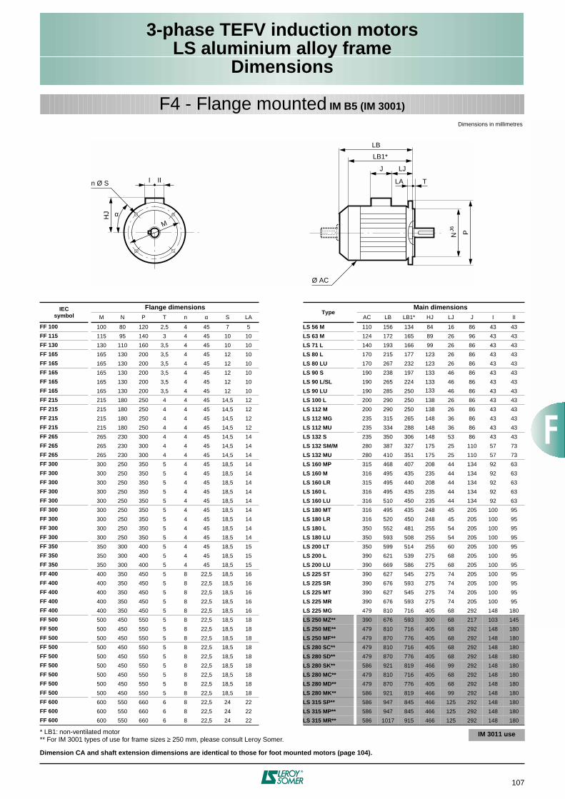
107
3-phase TEFV induction motorsLS aluminium alloy frame
Dimensions
F4 - Flange mounted IM B5 (IM 3001)
* LB1: non-ventilated motor** For IM 3001 types of use for frame sizes ≥ 250 mm, please consult Leroy Somer.
Dimension CA and shaft extension dimensions are identical to those for foot mounted motors (page 104).
IECsymbol
Flange dimensionsType
Main dimensionsM N P T n α S LA AC LB LB1* HJ LJ J I II
FF 100 100 80 120 2,5 4 45 7 5 LS 56 M 110 156 134 84 16 86 43 43
FF 115 115 95 140 3 4 45 10 10 LS 63 M 124 172 165 89 26 96 43 43
FF 130 130 110 160 3,5 4 45 10 10 LS 71 L 140 193 166 99 26 86 43 43
FF 165 165 130 200 3,5 4 45 12 10 LS 80 L 170 215 177 123 26 86 43 43
FF 165 165 130 200 3,5 4 45 12 10 LS 80 LU 170 267 232 123 26 86 43 43
FF 165 165 130 200 3,5 4 45 12 10 LS 90 S 190 238 197 133 46 86 43 43
FF 165 165 130 200 3,5 4 45 12 10 LS 90 L/SL 190 265 224 133 46 86 43 43
FF 165 165 130 200 3,5 4 45 12 10 LS 90 LU 190 285 250 133 46 86 43 43
FF 215 215 180 250 4 4 45 14,5 12 LS 100 L 200 290 250 138 26 86 43 43
FF 215 215 180 250 4 4 45 14,5 12 LS 112 M 200 290 250 138 26 86 43 43
FF 215 215 180 250 4 4 45 14,5 12 LS 112 MG 235 315 265 148 36 86 43 43
FF 215 215 180 250 4 4 45 14,5 12 LS 112 MU 235 334 288 148 36 86 43 43
FF 265 265 230 300 4 4 45 14,5 14 LS 132 S 235 350 306 148 53 86 43 43
FF 265 265 230 300 4 4 45 14,5 14 LS 132 SM/M 280 387 327 175 25 110 57 73
FF 265 265 230 300 4 4 45 14,5 14 LS 132 MU 280 410 351 175 25 110 57 73
FF 300 300 250 350 5 4 45 18,5 14 LS 160 MP 315 468 407 208 44 134 92 63
FF 300 300 250 350 5 4 45 18,5 14 LS 160 M 316 495 435 235 44 134 92 63
FF 300 300 250 350 5 4 45 18,5 14 LS 160 LR 315 495 440 208 44 134 92 63
FF 300 300 250 350 5 4 45 18,5 14 LS 160 L 316 495 435 235 44 134 92 63
FF 300 300 250 350 5 4 45 18,5 14 LS 160 LU 316 510 450 235 44 134 92 63
FF 300 300 250 350 5 4 45 18,5 14 LS 180 MT 316 495 435 248 45 205 100 95
FF 300 300 250 350 5 4 45 18,5 14 LS 180 LR 316 520 450 248 45 205 100 95
FF 300 300 250 350 5 4 45 18,5 14 LS 180 L 350 552 481 255 54 205 100 95
FF 300 300 250 350 5 4 45 18,5 14 LS 180 LU 350 593 508 255 54 205 100 95
FF 350 350 300 400 5 4 45 18,5 15 LS 200 LT 350 599 514 255 60 205 100 95
FF 350 350 300 400 5 4 45 18,5 15 LS 200 L 390 621 539 275 68 205 100 95
FF 350 350 300 400 5 4 45 18,5 15 LS 200 LU 390 669 586 275 68 205 100 95
FF 400 400 350 450 5 8 22,5 18,5 16 LS 225 ST 390 627 545 275 74 205 100 95
FF 400 400 350 450 5 8 22,5 18,5 16 LS 225 SR 390 676 593 275 74 205 100 95
FF 400 400 350 450 5 8 22,5 18,5 16 LS 225 MT 390 627 545 275 74 205 100 95
FF 400 400 350 450 5 8 22,5 18,5 16 LS 225 MR 390 676 593 275 74 205 100 95
FF 400 400 350 450 5 8 22,5 18,5 16 LS 225 MG 479 810 716 405 68 292 148 180
FF 500 500 450 550 5 8 22,5 18,5 18 LS 250 MZ** 390 676 593 300 68 217 103 145
FF 500 500 450 550 5 8 22,5 18,5 18 LS 250 ME** 479 810 716 405 68 292 148 180
FF 500 500 450 550 5 8 22,5 18,5 18 LS 250 MF** 479 870 776 405 68 292 148 180
FF 500 500 450 550 5 8 22,5 18,5 18 LS 280 SC** 479 810 716 405 68 292 148 180
FF 500 500 450 550 5 8 22,5 18,5 18 LS 280 SD** 479 870 776 405 68 292 148 180
FF 500 500 450 550 5 8 22,5 18,5 18 LS 280 SK** 586 921 819 466 99 292 148 180
FF 500 500 450 550 5 8 22,5 18,5 18 LS 280 MC** 479 810 716 405 68 292 148 180
FF 500 500 450 550 5 8 22,5 18,5 18 LS 280 MD** 479 870 776 405 68 292 148 180
FF 500 500 450 550 5 8 22,5 18,5 18 LS 280 MK** 586 921 819 466 99 292 148 180
FF 600 600 550 660 6 8 22,5 24 22 LS 315 SP** 586 947 845 466 125 292 148 180
FF 600 600 550 660 6 8 22,5 24 22 LS 315 MP** 586 947 845 466 125 292 148 180
FF 600 600 550 660 6 8 22,5 24 22 LS 315 MR** 586 1017 915 466 125 292 148 180
HJ
I II
M
n Ø S LA
J LJ
LB
T
N PJ6
Ø AC
α
LB1*
Dimensions in millimetres
IM 3011 use
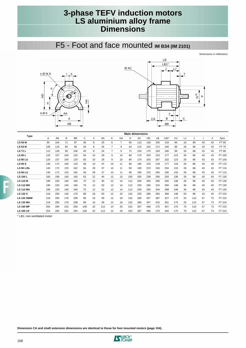
108
3-phase TEFV induction motorsLS aluminium alloy frame
Dimensions
F5 - Foot and face mounted IM B34 (IM 2101)
Dimensions in millimetres
* LB1: non-ventilated motor
Dimension CA and shaft extension dimensions are identical to those for foot mounted motors (page 104).
TypeMain dimensions
A AB B BB C X AA K HA H AC HD LB LB1* HJ LJ J I II Sym.
LS 56 M 90 104 71 87 36 8 25 6 7 56 110 140 156 134 84 16 86 43 43 FT 65
LS 63 M 100 115 80 96 40 8 26 7 9 63 124 152 172 165 89 26 86 43 43 FT 75
LS 71 L 112 126 90 106 45 8 24 7 9 71 140 170 193 166 99 26 86 43 43 FT 85
LS 80 L 125 157 100 120 50 10 29 9 10 80 170 203 215 177 123 26 86 43 43 FT 100
LS 80 LU 125 157 100 120 50 10 29 9 10 80 170 203 267 232 123 26 86 43 43 FT 100
LS 90 S 140 172 100 120 56 10 37 10 11 90 190 223 218 177 133 26 86 43 43 FT 115
LS 90 L/SL 140 172 125 162 56 28 37 10 11 90 190 223 245 204 133 26 86 43 43 FT 115
LS 90 LU 140 172 125 162 56 28 37 10 11 90 190 223 265 230 133 26 86 43 43 FT 115
LS 100 L 160 196 140 165 63 12 40 12 13 100 200 238 290 250 138 26 86 43 43 FT 130
LS 112 M 190 220 140 165 70 12 45 12 14 112 200 250 290 250 138 26 86 43 43 FT 130
LS 112 MG 190 220 140 165 70 12 52 12 14 112 235 260 315 265 148 36 86 43 43 FT 130
LS 112 MU 190 220 140 165 70 12 52 12 14 112 235 260 334 288 148 36 86 43 43 FT 130
LS 132 S 216 250 140 170 89 16 50 12 15 132 235 280 350 306 148 53 86 43 43 FT 215
LS 132 SM/M 216 250 178 208 89 16 59 12 18 132 280 307 387 327 175 25 110 57 73 FT 215
LS 132 MU 216 250 178 208 89 16 59 12 18 132 280 307 410 351 175 25 110 57 73 FT 215
LS 160 MP 254 294 210 250 108 20 112 14 25 315 307 468 175 407 175 70 110 57 73 FT 215
LS 160 LR 254 294 254 294 108 20 112 14 25 315 307 495 175 440 175 70 110 57 73 FT 215
A
HD
H HA
AB
AA4 Ø K
I
M
n Ø M.S II
J LJ
LB
T
N PJ6
Ø AC
x
B C
BB
CA
α
LB1*
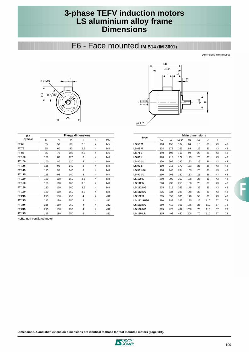
109
3-phase TEFV induction motorsLS aluminium alloy frame
Dimensions
F6 - Face mounted IM B14 (IM 3601)
Dimensions in millimetres
* LB1: non-ventilated motor
Dimension CA and shaft extension dimensions are identical to those for foot mounted motors (page 104).
IECsymbol
Flange dimensionsType
Main dimensionsM N P T n MS AC LB LB1* HJ LJ J I II
FT 65 65 50 80 2,5 4 M5 LS 56 M 110 156 134 84 16 86 43 43
FT 75 75 60 90 2,5 4 M5 LS 63 M 124 172 165 89 26 86 43 43
FT 85 85 70 105 2,5 4 M6 LS 71 L 140 193 166 99 26 86 43 43
FT 100 100 80 120 3 4 M6 LS 80 L 170 215 177 123 26 86 43 43
FT 100 100 80 120 3 4 M6 LS 80 LU 170 267 232 123 26 86 43 43
FT 115 115 95 140 3 4 M8 LS 90 S 190 218 177 133 26 86 43 43
FT 115 115 95 140 3 4 M8 LS 90 L/SL 190 245 204 133 26 86 43 43
FT 115 115 95 140 3 4 M8 LS 90 LU 190 265 230 133 26 86 43 43
FT 130 130 110 160 3,5 4 M8 LS 100 L 200 290 250 138 26 86 43 43
FT 130 130 110 160 3,5 4 M8 LS 112 M 200 290 250 138 26 86 43 43
FT 130 130 110 160 3,5 4 M8 LS 112 MG 235 315 265 148 36 86 43 43
FT 130 130 110 160 3,5 4 M8 LS 112 MU 235 334 288 148 36 86 43 43
FT 215 215 180 250 4 4 M12 LS 132 S 235 350 306 148 53 86 43 43
FT 215 215 180 250 4 4 M12 LS 132 SM/M 280 387 327 175 25 110 57 73
FT 215 215 180 250 4 4 M12 LS 132 MU 280 410 351 175 25 110 57 73
FT 215 215 180 250 4 4 M12 LS 160 MP 315 425 407 208 70 110 57 73
FT 215 215 180 250 4 4 M12 LS 160 LR 315 495 440 208 70 110 57 73
J LJ
LB
T
N PJ6
Ø AC
HJ
I
AC
M
n x MSII
α = 45°
LB1*
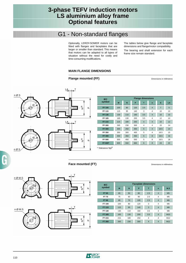
110
3-phase TEFV induction motorsLS aluminium alloy frame
Optional features
Optionally, LEROY-SOMER motors can befitted with flanges and faceplates that arelarger or smaller than standard. This meansthat motors can be adapted to all types ofsituation without the need for costly andtime-consuming modifications.
The tables below give flange and faceplatedimensions and flange/motor compatibility.
The bearing and shaft extension for eachframe size remain standard.
G1 - Non-standard flanges
MAIN FLANGE DIMENSIONS
Flange mounted (FF)
Dimensions in millimetres
* Tolerance Njs
6
Face mounted (FT)
Dimensions in millimetres
IECsymbol
Flange dimensions
M N P T n S LA
FF 100
100 80 120 2.5 4 7 5
FF 115
115 95 140 3 4 10 10
FF 130
130 110 160 3.5 4 10 10
FF 165
165 130 200 3.5 4 12 10
FF 215
215 180 250 4 4 15 12
FF 265
265 230 300 4 4 15 14
FF 300
300 250 350 5 4 18.5 14
FF 350
350 300 400 5 4 18.5 15
FF 400
400 350 450 5 8 18.5 16
FF 500
500 450 550 5 8 18.5 18
FF 600*
600 550 660 6 8 24 22
IECsymbol
Faceplate dimensions
M N P T n M.S
FT 65
65 50 80 2.5 4 M5
FT 75
75 60 90 2.5 4 M5
FT 85
85 70 105 2.5 4 M6
FT 100
100 80 120 3 4 M6
FT 115
115 95 140 3 4 M8
FT 130
130 110 160 3.5 4 M8
FT 165
165 130 200 3.5 4 M10
FT 215
215 180 250 4 4 M12
FT 265
265 230 300 4 4 M12
LA T
N PJ6
M
n Ø S
LA T
N PJ6
M
n Ø S
M
n Ø M.ST
N PJ6
T
N PJ6
M
n Ø M.S
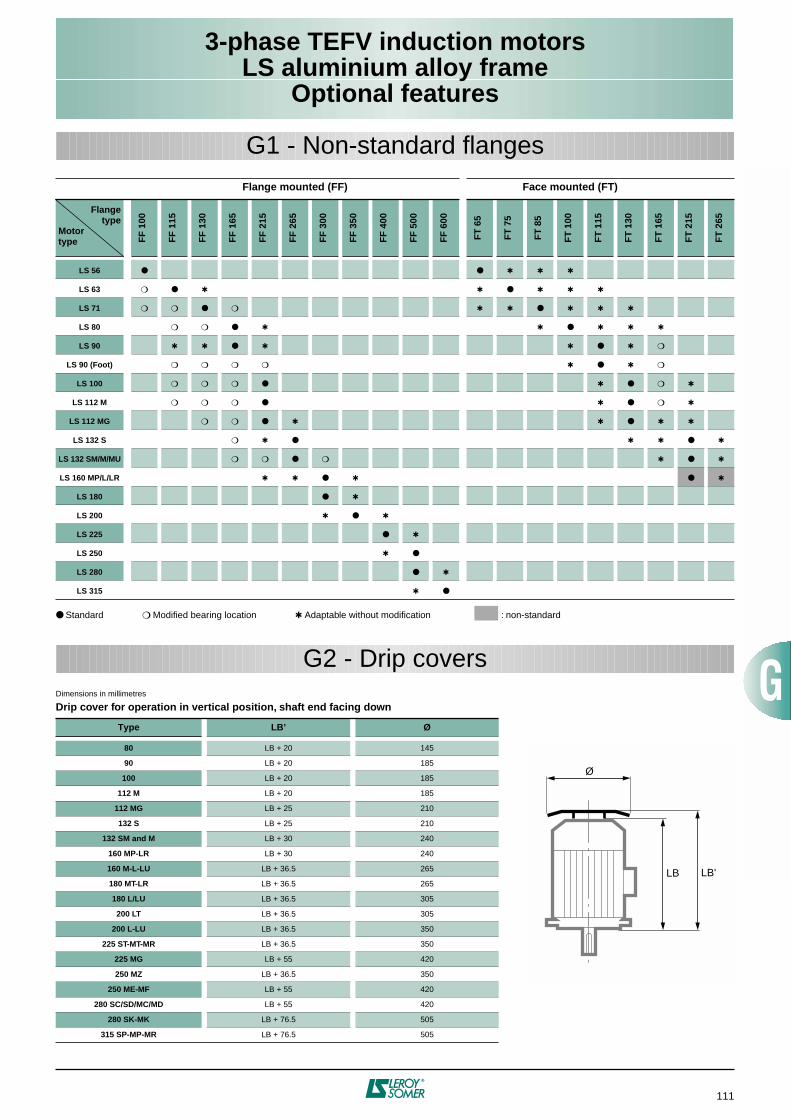
111
3-phase TEFV induction motorsLS aluminium alloy frame
Optional features
G1 - Non-standard flanges
Standard
Modified bearing location
Adaptable without modification
: non-standard
Flange mounted (FF) Face mounted (FT)
Flangetype
Motortype F
F 1
00
FF
115
FF
130
FF
165
FF
215
FF
265
FF
300
FF
350
FF
400
FF
500
FF
600
FT
65
FT
75
FT
85
FT
100
FT
115
FT
130
FT
165
FT
215
FT
265
LS 56
LS 63
LS 71
LS 80
LS 90
LS 90 (Foot)
LS 100
LS 112 M
LS 112 MG
LS 132 S
LS 132 SM/M/MU
LS 160 MP/L/LR
LS 180
LS 200
LS 225
LS 250
LS 280
LS 315
G2 - Drip covers
Dimensions in millimetres
Drip cover for operation in vertical position, shaft end facing down
Type LB’ Ø
80
LB + 20 145
90
LB + 20 185
100
LB + 20 185
112 M
LB + 20 185
112 MG
LB + 25 210
132 S
LB + 25 210
132 SM and M
LB + 30 240
160 MP-LR
LB + 30 240
160 M-L-LU
LB + 36.5 265
180 MT-LR
LB + 36.5 265
180 L/LU
LB + 36.5 305
200 LT
LB + 36.5 305
200 L-LU
LB + 36.5 350
225 ST-MT-MR
LB + 36.5 350
225 MG
LB + 55 420
250 MZ
LB + 36.5 350
250 ME-MF
LB + 55 420
280 SC/SD/MC/MD
LB + 55 420
280 SK-MK
LB + 76.5 505
315 SP-MP-MR
LB + 76.5 505
LB LB'
Ø
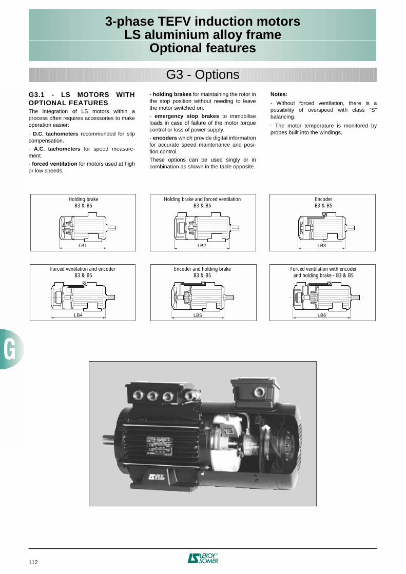
112
3-phase TEFV induction motorsLS aluminium alloy frame
Optional features
G3.1 - LS MOTORS WITHOPTIONAL FEATURES
The integration of LS motors within aprocess often requires accessories to makeoperation easier:
-
D.C. tachometers
recommended for slipcompensation.
-
A.C. tachometers
for speed measure-ment.
-
forced ventilation
for motors used at highor low speeds.
-
holding brakes
for maintaining the rotor inthe stop position without needing to leavethe motor switched on.
-
emergency stop brakes
to immobiliseloads in case of failure of the motor torquecontrol or loss of power supply.
-
encoders
which provide digital informationfor accurate speed maintenance and posi-tion control.
These options can be used singly or incombination as shown in the table opposite.
Notes:
- Without forced ventilation, there is apossibility of overspeed with class "S"balancing.
- The motor temperature is monitored byprobes built into the windings.
G3 - Options
LB1
Holding brakeB3 & B5
Holding brake and forced ventilationB3 & B5
EncoderB3 & B5
Forced ventilation and encoder B3 & B5
Encoder and holding brakeB3 & B5
Forced ventilation with encoderand holding brake - B3 & B5
LB2 LB3
LB4 LB6LB5
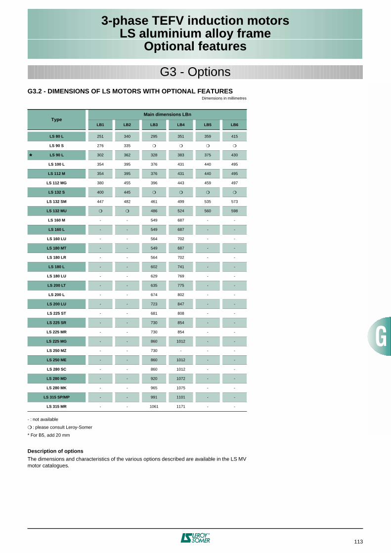
113
3-phase TEFV induction motorsLS aluminium alloy frame
Optional features
G3.2 - DIMENSIONS OF LS MOTORS WITH OPTIONAL FEATURES
Dimensions in millimetres
- : not available
: please consult Leroy-Somer
* For B5, add 20 mm
Description of options
The dimensions and characteristics of the various options described are available in the LS MVmotor catalogues.
TypeMain dimensions LBn
LB1 LB2 LB3 LB4 LB5 LB6
LS 80 L
251 340 295 351 359 415
LS 90 S
276 335
*
LS 90 L
302 362 328 383 375 430
LS 100 L
354 395 376 431 440 495
LS 112 M
354 395 376 431 440 495
LS 112 MG
380 455 396 443 459 497
LS 132 S
400 445
LS 132 SM
447 482 461 499 535 573
LS 132 MU
486 524 560 598
LS 160 M
- - 549 687 - -
LS 160 L
- - 549 687 - -
LS 160 LU
- - 564 702 - -
LS 180 MT
- - 549 687 - -
LS 180 LR
- - 564 702 - -
LS 180 L
- - 602 741 - -
LS 180 LU
- - 629 769 - -
LS 200 LT
- - 635 775 - -
LS 200 L
- - 674 802 - -
LS 200 LU
- - 723 847 - -
LS 225 ST
- - 681 808 - -
LS 225 SR
- - 730 854 - -
LS 225 MR
- - 730 854 - -
LS 225 MG
- - 860 1012 - -
LS 250 MZ
- - 730 - - -
LS 250 ME
- - 860 1012 - -
LS 280 SC
- - 860 1012 - -
LS 280 MD
- - 920 1072 - -
LS 280 MK
- - 965 1075 - -
LS 315 SP/MP
- - 991 1101 - -
LS 315 MR
- - 1061 1171 - -
G3 - Options
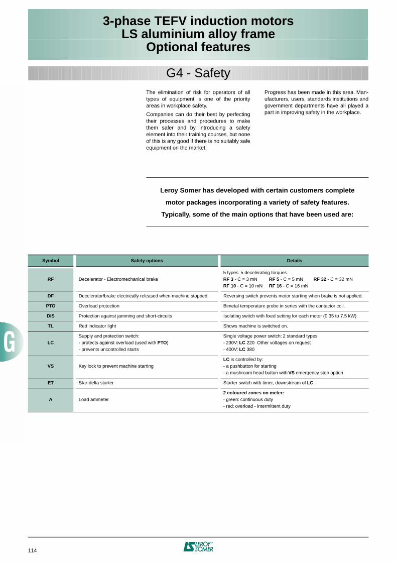
114
3-phase TEFV induction motorsLS aluminium alloy frame
Optional features
G4 - Safety
The elimination of risk for operators of alltypes of equipment is one of the priorityareas in workplace safety.
Companies can do their best by perfectingtheir processes and procedures to makethem safer and by introducing a safetyelement into their training courses, but noneof this is any good if there is no suitably safeequipment on the market.
Progress has been made in this area. Man-ufacturers, users, standards institutions andgovernment departments have all played apart in improving safety in the workplace.
Leroy Somer has developed with certain customers complete
motor packages incorporating a variety of safety features.
Typically, some of the main options that have been used are:
Symbol Safety options Details
RF
Decelerator - Electromechanical brake5 types: 5 decelerating torques
RF 3
- C = 3 mN
RF 5
- C = 5 mN
RF 32
- C = 32 mN
RF 10
- C = 10 mN
RF 16
- C = 16 mN
DF
Decelerator/brake electrically released when machine stopped Reversing switch prevents motor starting when brake is not applied.
PTO
Overload protection Bimetal temperature probe in series with the contactor coil.
DIS
Protection against jamming and short-circuits Isolating switch with fixed setting for each motor (0.35 to 7.5 kW).
TL
Red indicator light Shows machine is switched on.
LC
Supply and protection switch:- protects against overload (used with
PTO
)- prevents uncontrolled starts
Single voltage power switch: 2 standard types- 230V:
LC
220 Other voltages on request- 400V:
LC
380
VS
Key lock to prevent machine starting
LC
is controlled by:- a pushbutton for starting- a mushroom head button with
VS
emergency stop option
ET
Star-delta starter Starter switch with timer, downstream of
LC
.
A
Load ammeter
2 coloured zones on meter:
- green: continuous duty- red: overload - intermittent duty
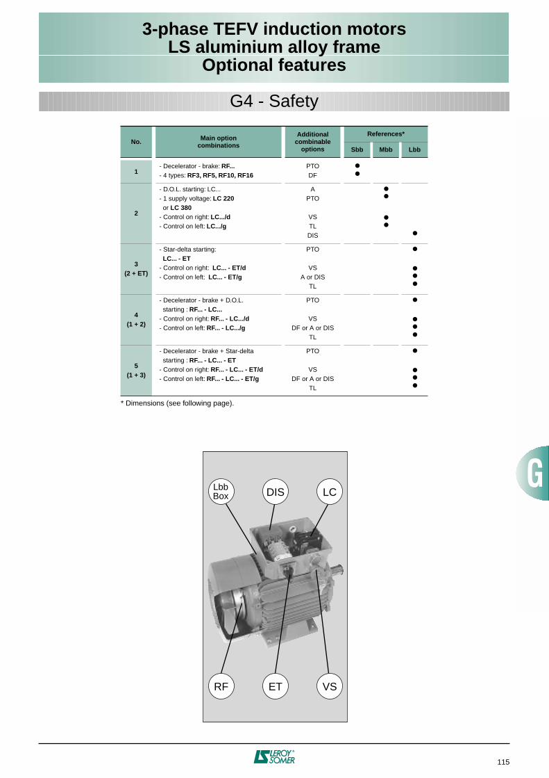
115
3-phase TEFV induction motorsLS aluminium alloy frame
Optional features
* Dimensions (see following page).
No. Main optioncombinations
Additionalcombinable
options
References*
Sbb Mbb Lbb
1- Decelerator - brake: RF...- 4 types: RF3, RF5, RF10, RF16
PTODF
2
- D.O.L. starting: LC...- 1 supply voltage: LC 220 or LC 380- Control on right: LC.../d- Control on left: LC.../g
APTO
VSTLDIS
3(2 + ET)
- Star-delta starting: LC... - ET- Control on right: LC... - ET/d- Control on left: LC... - ET/g
PTO
VSA or DIS
TL
4(1 + 2)
- Decelerator - brake + D.O.L. starting : RF... - LC...- Control on right: RF... - LC.../d- Control on left: RF... - LC.../g
PTO
VSDF or A or DIS
TL
5(1 + 3)
- Decelerator - brake + Star-delta starting : RF... - LC... - ET- Control on right: RF... - LC... - ET/d- Control on left: RF... - LC... - ET/g
PTO
VSDF or A or DIS
TL
LbbBox DIS LC
VSETRF
G4 - Safety
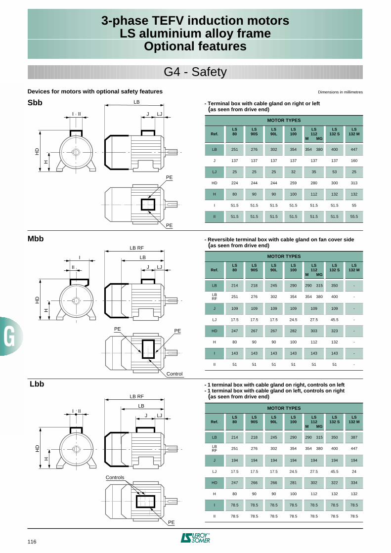
116
3-phase TEFV induction motorsLS aluminium alloy frame
Optional features
Devices for motors with optional safety features Dimensions in millimetres
Sbb - Terminal box with cable gland on right or left (as seen from drive end)
Mbb - Reversible terminal box with cable gland on fan cover side (as seen from drive end)
Lbb - 1 terminal box with cable gland on right, controls on left- 1 terminal box with cable gland on left, controls on right (as seen from drive end)
MOTOR TYPES
Ref.LS80
LS90S
LS90L
LS100
LS112
M MG
LS132 S
LS132 M
LB 251 276 302 354 354 380 400 447
J 137 137 137 137 137 137 160
LJ 25 25 25 32 35 53 25
HD 224 244 244 259 280 300 313
H 80 90 90 100 112 132 132
I 51.5 51.5 51.5 51.5 51.5 51.5 55
II 51.5 51.5 51.5 51.5 51.5 51.5 55.5
MOTOR TYPES
Ref.LS80
LS90S
LS90L
LS100
LS112
M MG
LS132 S
LS132 M
LB 214 218 245 290 290 315 350 -
LBRF 251 276 302 354 354 380 400 -
J 109 109 109 109 109 109 -
LJ 17.5 17.5 17.5 24.5 27.5 45.5 -
HD 247 267 267 282 303 323 -
H 80 90 90 100 112 132 -
I 143 143 143 143 143 143 -
II 51 51 51 51 51 51 -
MOTOR TYPES
Ref.LS80
LS90S
LS90L
LS100
LS112
M MG
LS132 S
LS132 M
LB 214 218 245 290 290 315 350 387
LBRF 251 276 302 354 354 380 400 447
J 194 194 194 194 194 194 194
LJ 17.5 17.5 17.5 24.5 27.5 45.5 24
HD 247 266 266 281 302 322 334
H 80 90 90 100 112 132 132
I 78.5 78.5 78.5 78.5 78.5 78.5 78.5
II 78.5 78.5 78.5 78.5 78.5 78.5 78.5
HD
H
I
J LJ
LB
PE
PE
HD
H
II J LJ
LB RF
PE
Control
HD
H
II
I LB
PE
J LJ
LB RF
PE
LB
Controls
I II
G4 - Safety
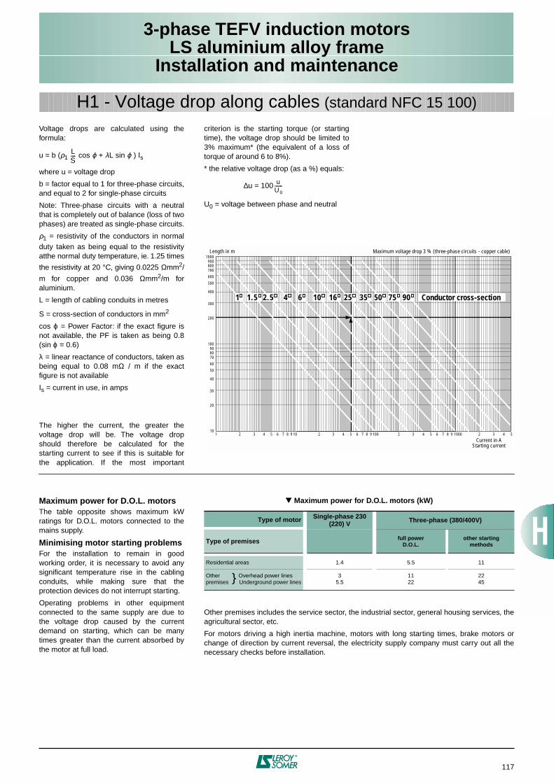
117
3-phase TEFV induction motorsLS aluminium alloy frame
Installation and maintenance
Voltage drops are calculated using theformula:
u = b (
ρ
1
cos
ϕ
+
λ
L sin
ϕ
) I
s
where
u
= voltage drop
b
= factor equal to 1 for three-phase circuits,and equal to 2 for single-phase circuits
Note: Three-phase circuits with a neutralthat is completely out of balance (loss of twophases) are treated as single-phase circuits.
ρ
1
= resistivity of the conductors in normalduty taken as being equal to the resistivityatthe normal duty temperature, ie. 1.25 times
the resistivity at 20 °C, giving 0.0225
Ω
mm
2
/
m for copper and 0.036
Ω
mm
2
/m foraluminium.
L
= length of cabling conduits in metres
S = cross-section of conductors in mm
2
cos
ϕ
= Power Factor: if the exact figure isnot available, the PF is taken as being 0.8(sin
ϕ
= 0.6)
λ
= linear reactance of conductors, taken asbeing equal to 0.08 m
Ω
/ m if the exactfigure is not available
I
s
= current in use, in amps
The higher the current, the greater thevoltage drop will be. The voltage dropshould therefore be calculated for thestarting current to see if this is suitable forthe application. If the most important
LS----
H1 - Voltage drop along cables
(standard NFC 15 100)
criterion is the starting torque (or startingtime), the voltage drop should be limited to3% maximum* (the equivalent of a loss oftorque of around 6 to 8%).
* the relative voltage drop (as a %) equals:
∆
u = 100
U
0
= voltage between phase and neutral
uU0------
1 2 3 4 5 6 7 8 9 10 2 3 4 5 6 7 8 9 100 2 3 4 5 2 3 4 56 7 8 9 100010
20
30
40
50
60
708090
100
200
300
400
500
600
700800900
1000Length in m Maximum voltage drop 3 % (three-phase circuits - copper cable)
Current in AStarting current
1 1.5 2.5 4 6 10 16 35 50 75 9025 Conductor cross-section
Maximum power for D.O.L. motors
The table opposite shows maximum kWratings for D.O.L. motors connected to themains supply.
Minimising motor starting problems
For the installation to remain in goodworking order, it is necessary to avoid anysignificant temperature rise in the cablingconduits, while making sure that theprotection devices do not interrupt starting.
Operating problems in other equipmentconnected to the same supply are due tothe voltage drop caused by the currentdemand on starting, which can be manytimes greater than the current absorbed bythe motor at full load.
Maximum power for D.O.L. motors (kW)
Other premises includes the service sector, the industrial sector, general housing services, theagricultural sector, etc.
For motors driving a high inertia machine, motors with long starting times, brake motors orchange of direction by current reversal, the electricity supply company must carry out all thenecessary checks before installation.
Type of motor Single-phase 230 (220) V Three-phase (380/400V)
Type of premises
full powerD.O.L.
other startingmethods
Residential areas
1.4 5.5 11
Other Overhead power linespremises Underground power lines
35.5
1122
2245
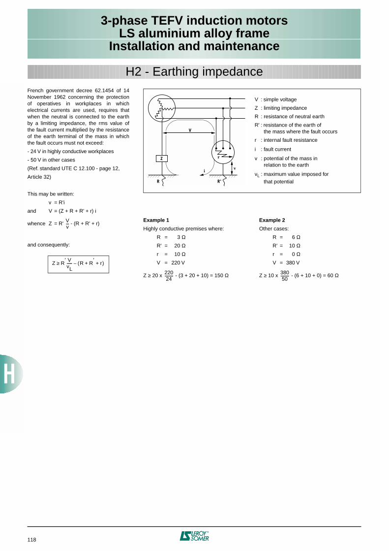
118
3-phase TEFV induction motorsLS aluminium alloy frame
Installation and maintenance
French government decree 62.1454 of 14November 1962 concerning the protectionof operatives in workplaces in whichelectrical currents are used, requires thatwhen the neutral is connected to the earthby a limiting impedance, the rms value ofthe fault current multiplied by the resistanceof the earth terminal of the mass in whichthe fault occurs must not exceed:
- 24 V in highly conductive workplaces
- 50 V in other cases
(Ref. standard UTE C 12.100 - page 12,
Article 32)
This may be written:
v = R'i
and V = (Z + R + R' + r) i
whence Z = R' - (R + R' + r)
and consequently:
Vv----
Z R′ VvL------ R R
′r+ +( )–≥
H2 - Earthing impedance
Example 1
Highly conductive premises where:
R = 3
Ω
R' = 20
Ω
r = 10
Ω
V = 220 V
Z
≥
20 x - (3 + 20 + 10) = 150
Ω
Example 2
Other cases:
R = 6
Ω
R' = 10
Ω
r = 0
Ω
V = 380 V
Z
≥
10 x - (6 + 10 + 0) = 60
Ω
Z
R R'
V
iv
r
V : simple voltage
Z : limiting impedance
R : resistance of neutral earth
R' : resistance of the earth of the mass where the fault occurs
r : internal fault resistance
i : fault current
v : potential of the mass in relation to the earth
vL : maximum value imposed for that potential
22024
----------38050
----------
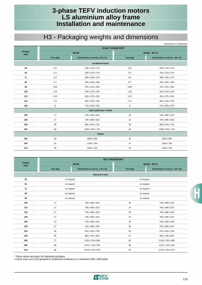
119
3-phase TEFV induction motorsLS aluminium alloy frame
Installation and maintenance
Dimensions in millimetres
- These values are given for individual packages- Frame sizes up to 132 grouped in cardboard containers on a standard 1200 x 800 pallet
Framesize
ROAD TRANSPORT
IM B3 IM B5 - IM V1
Tare (kg) Dimensions in mm (L x W x H) Tare (kg) Dimensions in mm (L x W x H)
Cardboard boxes
56
0.3 230 x 120 x 170 0.3 230 x 120 x 170
63
0.3 230 x 120 x 170 0.3 230 x 120 x 170
71
0.4 305 x 155 x 170 0.4 305 x 155 x 170
80
0.7 330 x 205 x 255 0.7 330 x 205 x 255
90
0.85 375 x 215 x 285 0.85 375 x 215 x 285
100
1.25 420 x 270 x 320 1.25 420 x 270 x 320
112
1.25 420 x 270 x 320 1.25 420 x 270 x 320
132
2.9 560 x 320 x 375 2.9 560 x 320 x 375
160
8 710 x 500 x 570 8 710 x 500 x 570
Open pallet box or laths
160
17 740 x 480 x 610 18 740 x 480 x 610
180
17 740 x 480 x 610 18 740 x 480 x 610
200
38 890 x 570 x 710 35 890 x 570 x 710
225
56 1000 x 870 x 720 48 1000 x 870 x 720
Pallets
250
18 1000 x 600 22 1000 x 600
280
20 1200 x 700 24 1200 x 700
315
20 1200 x 700 24 1200 x 700
Framesize
SEA TRANSPORT
IM B3 IM B5 - IM V1
Tare (kg) Dimensions in mm (L x W x H) Tare (kg) Dimensions in mm (L x W x H)
Plywood crates
56
on request on request
63
on request on request
71
on request on request
80
on request on request
90
on request on request
100
17 740 x 480 x 610 18 740 x 480 x 610
112
17 740 x 480 x 610 18 740 x 480 x 610
132
17 740 x 480 x 610 18 740 x 480 x 610
160
17 740 x 480 x 610 18 740 x 480 x 610
160
17 740 x 480 x 610 18 740 x 480 x 610
180
17 740 x 480 x 610 18 740 x 480 x 610
200
48 910 x 620 x 750 50 910 x 620 x 750
225
55 960 x 750 x 830 57 960 x 750 x 830
250
77 1120 x 750 x 890 82 1120 x 750 x 890
280
86 1270 x 720 x 970 90 1270 x 720 x 970
315
86 1270 x 720 x 970 90 1270 x 720 x 970
H3 - Packaging weights and dimensions
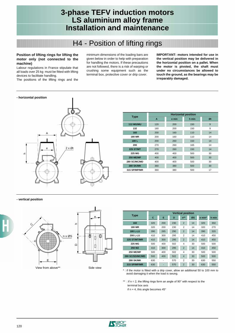
120
3-phase TEFV induction motorsLS aluminium alloy frame
Installation and maintenance
Position of lifting rings for lifting themotor only (not connected to themachine)
Labour regulations in France stipulate thatall loads over 25 kg must be fitted with liftingdevices to facilitate handling.The positions of the lifting rings and the
minimum dimensions of the loading bars aregiven below in order to help with preparationfor handling the motors. If these precautionsare not followed, there is a risk of warping orcrushing some equipment such as theterminal box, protective cover or drip cover.
IMPORTANT: motors intended for use inthe vertical position may be delivered inthe horizontal position on a pallet. Whenthe motor is pivoted, the shaft mustunder no circumstances be allowed totouch the ground, as the bearings may beirreparably damaged.
H4 - Position of lifting rings
- horizontal position
- vertical position
* : if the motor is fitted with a drip cover, allow an additional 50 to 100 mm toavoid damaging it when the load is swung.
** : if n = 2, the lifting rings form an angle of 90° with respect to theterminal box axisif n = 4, this angle becomes 45°
TypeHorizontal position
A e min h min Øt
112 MG/MU
120 200 150 9
132
160 200 150 9
160
200 160 110 14
180 MR
200 160 110 14
180 L
200 260 150 14
200
270 260 165 14
225 ST/MT
270 260 150 14
225 MG
400 400 500 30
250 ME/MF
400 400 500 30
280 SC/MC/MD
400 400 500 30
280 SK/MK
360 380 500 30
315 SP/MP/MR
360 380 500 17
TypeVertical position
C E D n** ØS e min* h min
160
320 200 230 2 14 320 350
180 MR
320 200 230 2 14 320 270
180 L-LU
390 265 290 2 14 390 320
200 L-LU
410 300 295 2 14 410 450
225 ST/MT/MR
410 300 295 2 14 410 450
225 MG
500 400 502 4 30 500 500
250 MZ
410 300 295 2 14 410 450
250 ME/MF
500 400 502 4 30 500 500
280 SC/SD/MC/MD
500 400 502 4 30 500 500
280 SK/MK
630 - 570 2 30 630 550
315 SP/MP/MR
630 - 570 2 30 630 550
e
A
h
2 x Øt
e
h
n x ØS
D
E
C
View from above** Side view
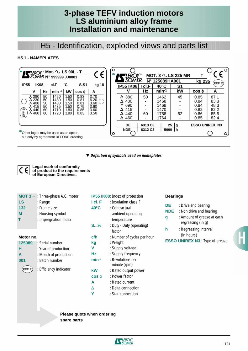
121
3-phase TEFV induction motorsLS aluminium alloy frame
Installation and maintenance
H5 - Identification, exploded views and parts list
H5.1 - NAMEPLATES
Definition of symbols used on nameplates
Legal mark of conformityof product to the requirementsof European Directives.
* *
*Other logos may be used as an option, but only by agreement BEFORE ordering
N° 999999 JJ0001Mot. LS 90L - T
IP55 IK08 cl.F °C S.S1 kg 18
V Hz min -1 kW cos ϕ A380230400415440460
142014301430143517101720
1.501.501.501.501.801.80
0.830.810.810.790.850.83
3.706.203.603.603.603.50
505050506060
MOT. 3
IP55 IK08 I cl.F S1V Hz min-1 kW cos ϕ A
N° 125089HA001 kg
6313 C36312 C3
LS 225 MR T235
40°C
380400690415440460
50---
60-
146214681468147017581764
45---
52-
0.850.840.840.820.860.85
87.183.348.382.285.582.4
255000
ESSODENDE
gh
UNIREX N3
MOT 3 ~
: Three-phase A.C. motor
LS
: Range
132
: Frame size
M
: Housing symbol
T
: Impregnation index
Motor no.
125089 : Serial number H : Year of production A : Month of production 001 : Batch number
: Efficiency indicator
IP55 IK08: Index of protectionI cl. F : Insulation class F40°C : Contractual
ambient operating temperature
S...% : Duty - Duty (operating) factor
c/h : Number of cycles per hourkg : WeightV : Supply voltageHz : Supply frequencymin-1 : Revolutions per
minute (rpm)kW : Rated output powercos ϕ : Power factorA : Rated current∆ : Delta connectionY : Star connection
Bearings
DE : Drive end bearingNDE : Non drive end bearingg : Amount of grease at each
regreasing (in g)
h : Regreasing interval (in hours)
ESSO UNIREX N3 : Type of grease
Please quote when orderingspare parts
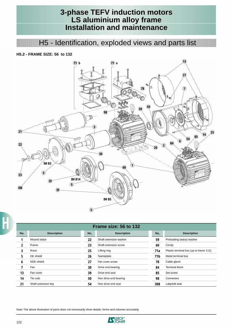
122
3-phase TEFV induction motorsLS aluminium alloy frame
Installation and maintenance
H5 - Identification, exploded views and parts listH5.2 - FRAME SIZE: 56 to 132
Note: The above illustration of parts does not necessarily show details, forms and volumes accurately.
Frame size: 56 to 132No, Description No, Description No, Description
1 Wound stator 22 Shaft extension washer 59 Preloading (wavy) washer
2 Frame 23 Shaft extension screw 60 Circlip
3 Rotor 25 Lifting ring 71a Plastic terminal box (up to frame 112)
5 DE shield 26 Nameplate 71b Metal terminal box
6 NDE shield 27 Fan cover screw 78 Cable gland
7 Fan 30 Drive end bearing 84 Terminal block
13 Fan cover 39 Drive end seal 85 Set screw
14 Tie rods 50 Non drive end bearing 98 Connectors
21 Shaft extension key 54 Non drive end seal 308 Labyrinth seal
71 b
78
98
213
5
22
5
5
308
23
IM B3
IM B14
IM B5
13
7
2514
8554
684
262
160
5950
27
30
71 a
39
39
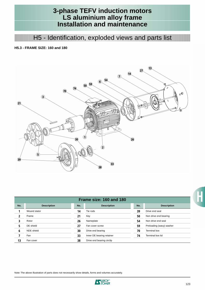
123
3-phase TEFV induction motorsLS aluminium alloy frame
Installation and maintenance
H5 - Identification, exploded views and parts listH5.3 - FRAME SIZE: 160 and 180
Note: The above illustration of parts does not necessarily show details, forms and volumes accurately.
Frame size: 160 and 180No. Description No. Description No. Description
1 Wound stator 14 Tie rods 39 Drive end seal
2 Frame 21 Key 50 Non drive end bearing
3 Rotor 26 Nameplate 54 Non drive end seal
5 DE shield 27 Fan cover screw 59 Preloading (wavy) washer
6 NDE shield 30 Drive end bearing 70 Terminal box
7 Fan 33 Inner DE bearing retainer 74 Terminal box lid
13 Fan cover 38 Drive end bearing circlip
1327
754
14
65950
7470
3
21
39
5
301
3833
26
2
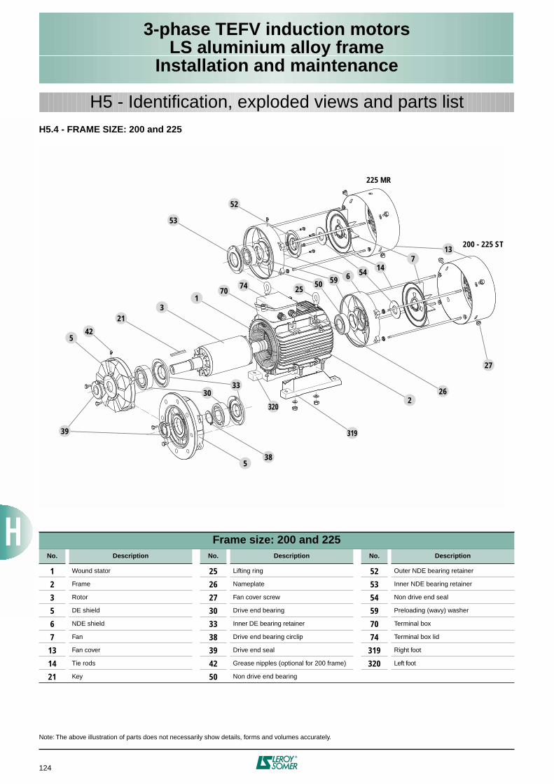
124
3-phase TEFV induction motorsLS aluminium alloy frame
Installation and maintenance
H5 - Identification, exploded views and parts listH5.4 - FRAME SIZE: 200 and 225
Note: The above illustration of parts does not necessarily show details, forms and volumes accurately.
Frame size: 200 and 225No. Description No. Description No. Description
1 Wound stator 25 Lifting ring 52 Outer NDE bearing retainer
2 Frame 26 Nameplate 53 Inner NDE bearing retainer
3 Rotor 27 Fan cover screw 54 Non drive end seal
5 DE shield 30 Drive end bearing 59 Preloading (wavy) washer
6 NDE shield 33 Inner DE bearing retainer 70 Terminal box
7 Fan 38 Drive end bearing circlip 74 Terminal box lid
13 Fan cover 39 Drive end seal 319 Right foot
14 Tie rods 42 Grease nipples (optional for 200 frame) 320 Left foot
21 Key 50 Non drive end bearing
542
39
538
3033
320
319
26
27
2
213
170
74
53
52
25
13
225 MR
200 - 225 ST
50 59 6 54 147
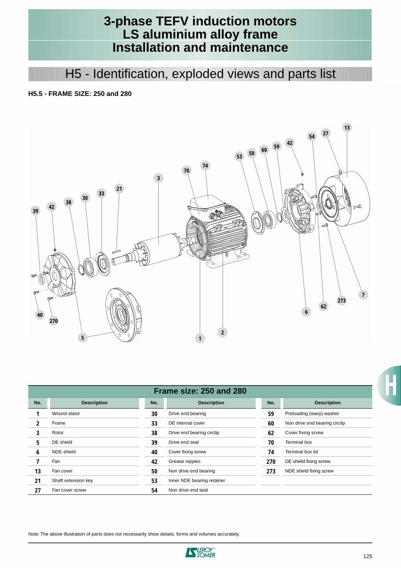
125
3-phase TEFV induction motorsLS aluminium alloy frame
Installation and maintenance
H5 - Identification, exploded views and parts listH5.5 - FRAME SIZE: 250 and 280
Note: The above illustration of parts does not necessarily show details, forms and volumes accurately.
Frame size: 250 and 280No. Description No. Description No. Description
1 Wound stator 30 Drive end bearing 59 Preloading (wavy) washer
2 Frame 33 DE internal cover 60 Non drive end bearing circlip
3 Rotor 38 Drive end bearing circlip 62 Cover fixing screw
5 DE shield 39 Drive end seal 70 Terminal box
6 NDE shield 40 Cover fixing screw 74 Terminal box lid
7 Fan 42 Grease nipples 270 DE shield fixing screw
13 Fan cover 50 Non drive end bearing 273 NDE shield fixing screw
21 Shaft extension key 53 Inner NDE bearing retainer
27 Fan cover screw 54 Non drive end seal
15
270
3
1327
21
5059
4260
54
53
7074
3033
3842
2
662
2737
40
39
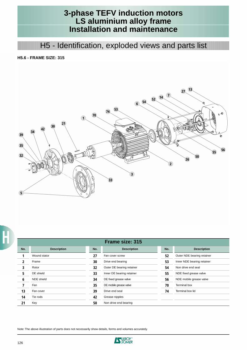
126
3-phase TEFV induction motorsLS aluminium alloy frame
Installation and maintenance
H5 - Identification, exploded views and parts listH5.6 - FRAME SIZE: 315
Note: The above illustration of parts does not necessarily show details, forms and volumes accurately.
Frame size: 315No. Description No. Description No. Description
1 Wound stator 27 Fan cover screw 52 Outer NDE bearing retainer
2 Frame 30 Drive end bearing 53 Inner NDE bearing retainer
3 Rotor 32 Outer DE bearing retainer 54 Non drive end seal
5 DE shield 33 Inner DE bearing retainer 55 NDE fixed grease valve
6 NDE shield 34 DE fixed grease valve 56 NDE mobile grease valve
7 Fan 35 DE mobile grease valve 70 Terminal box
13 Fan cover 39 Drive end seal 74 Terminal box lid
14 Tie rods 42 Grease nipples
21 Key 50 Non drive end bearing
5
39
32
35
34
3021
33
3
2
5055
56
1
53
6 5452 14 7
1327
42
26
7074
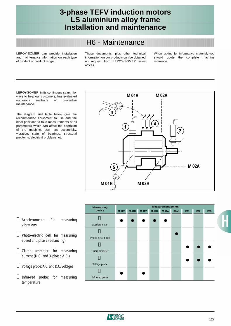
127
3-phase TEFV induction motorsLS aluminium alloy frame
Installation and maintenance
H6 - MaintenanceLEROY-SOMER can provide installationand maintenance information on each typeof product or product range.
These documents, plus other technicalinformation on our products can be obtainedon request from LEROY-SOMER salesoffices.
When asking for informative material, youshould quote the complete machinereference.
LEROY-SOMER, in its continuous search forways to help our customers, has evaluatednumerous methods of preventivemaintenance.
The diagram and table below give therecommended equipment to use and theideal positions to take measurements of allparameters which can affect the operationof the machine, such as eccentricity,vibration, state of bearings, structuralproblems, electrical problems, etc
M 01V M 02V
M 02A
M 02HM 01H
1
3
42
5
➀ Accelerometer: for measuringvibrations
➁ Photo-electric cell: for measuringspeed and phase (balancing)
➂ Clamp ammeter: for measuringcurrent (D.C. and 3-phase A.C.)
➃ Voltage probe: A.C. and D.C. voltages
➄ Infra-red probe: for measuringtemperature
Measauringdevice
Measurement points
M 01V M 01H M 02V M 02H M 02A Shaft E01 E02 E03
➀Accelerometer
➁Photo-electric cell
➂Clamp ammeter
➃Voltage probe
➄Infra-red probe
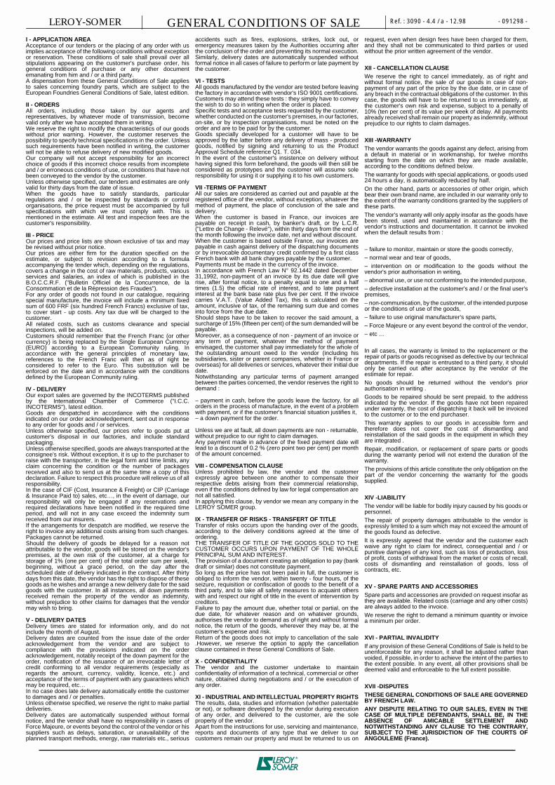
Ref. : 3090 - 4.4 / a - 12.98 - 091298 -GENERAL CONDITIONS OF SALELEROY-SOMERI - APPLICATION AREAAcceptance of our tenders or the placing of any order with usimplies acceptance of the following conditions without exceptionor reservation. These conditions of sale shall prevail over allstipulations appearing on the customer's purchase order, hisgeneral conditions of purchase or any other documentemanating from him and / or a third party.A dispensation from these General Conditions of Sale appliesto sales concerning foundry parts, which are subject to theEuropean Foundries General Conditions of Sale, latest edition.
II - ORDERSAll orders, including those taken by our agents andrepresentatives, by whatever mode of transmission, becomevalid only after we have accepted them in writing.We reserve the right to modify the characteristics of our goodswithout prior warning. However, the customer reserves thepossibility to specify technical specifications in the order. Unlesssuch requirements have been notified in writing, the customerwill not be able to refuse delivery of new modified goods.Our company will not accept responsibility for an incorrectchoice of goods if this incorrect choice results from incompleteand / or erroneous conditions of use, or conditions that have notbeen conveyed to the vendor by the customer.Unless otherwise specified, our tenders and estimates are onlyvalid for thirty days from the date of issue.When the goods have to satisfy standards, particularregulations and / or be inspected by standards or controlorganisations, the price request must be accompanied by fullspecifications with which we must comply with. This ismentioned in the estimate. All test and inspection fees are thecustomer's responsibility.
III - PRICEOur prices and price lists are shown exclusive of tax and maybe revised without prior notice.Our prices are either firm for the duration specified on theestimate, or subject to revision according to a formulaaccompanying the tender which, depending on the regulations,covers a change in the cost of raw materials, products, variousservices and salaries, an index of which is published in theB.O.C.C.R.F. ("Bulletin Officiel de la Concurrence, de laConsommation et de la Répression des Fraudes").For any order of goods not found in our catalogue, requiringspecial manufacture, the invoice will include a minimum fixedsum of 600 FRF (six hundred French Francs) exclusive of tax,to cover start - up costs. Any tax due will be charged to thecustomer.All related costs, such as customs clearance and specialinspections, will be added on.Customers should remember that the French Franc (or othercurrency) is being replaced by the Single European Currency(EURO) according to a European Community ruling. Inaccordance with the general principles of monetary law,references to the French Franc will then as of right beconsidered to refer to the Euro. This substitution will beenforced on the date and in accordance with the conditionsdefined by the European Community ruling.
IV - DELIVERYOur export sales are governed by the INCOTERMS publishedby the International Chamber of Commerce ("I.C.C.INCOTERMS"), latest edition.Goods are despatched in accordance with the conditionsindicated on our order acknowledgement, sent out in responseto any order for goods and / or services.Unless otherwise specified, our prices refer to goods put atcustomer's disposal in our factories, and include standardpackaging.Unless otherwise specified, goods are always transported at theconsignee's risk. Without exception, it is up to the purchaser toraise with the transporter, in the legal form and time limits, anyclaim concerning the condition or the number of packagesreceived and also to send us at the same time a copy of thisdeclaration. Failure to respect this procedure will relieve us of allresponsibility.In the case of CIF (Cost, Insurance & Freight) or CIP (Carriage& Insurance Paid to) sales, etc…, in the event of damage, ourresponsibility will only be engaged if any reservations andrequired declarations have been notified in the required timeperiod, and will not in any case exceed the indemnity sumreceived from our insurers.If the arrangements for despatch are modified, we reserve theright to invoice any additional costs arising from such changes.Packages cannot be returned.Should the delivery of goods be delayed for a reason notattributable to the vendor, goods will be stored on the vendor'spremises, at the own risk of the customer, at a charge forstorage of 1% (one per cent) of the total order sum per week,beginning, without a grace period, on the day after thescheduled date of delivery indicated in the contract. After thirtydays from this date, the vendor has the right to dispose of thesegoods as he wishes and arrange a new delivery date for the saidgoods with the customer. In all instances, all down paymentsreceived remain the property of the vendor as indemnity,without prejudice to other claims for damages that the vendormay wish to bring.
V - DELIVERY DATESDelivery times are stated for information only, and do notinclude the month of August.Delivery dates are counted from the issue date of the orderacknowledgement from the vendor and are subject tocompliance with the provisions indicated on the orderacknowledgement, notably receipt of the down payment for theorder, notification of the issuance of an irrevocable letter ofcredit conforming to all vendor requirements (especially asregards the amount, currency, validity, licence, etc.) andacceptance of the terms of payment with any guarantees whichmay be required, etc…In no case does late delivery automatically entitle the customerto damages and / or penalties.Unless otherwise specified, we reserve the right to make partialdeliveries.Delivery dates are automatically suspended without formalnotice, and the vendor shall have no responsibility in cases ofForce Majeure, or events beyond the control of the vendor or hissuppliers such as delays, saturation, or unavailability of theplanned transport methods, energy, raw materials etc., serious
accidents such as fires, explosions, strikes, lock out, oremergency measures taken by the Authorities occurring afterthe conclusion of the order and preventing its normal execution.Similarly, delivery dates are automatically suspended withoutformal notice in all cases of failure to perform or late payment bythe customer.
VI - TESTSAll goods manufactured by the vendor are tested before leavingthe factory in accordance with vendor's ISO 9001 certifications.Customers may attend these tests : they simply have to conveythe wish to do so in writing when the order is placed.Specific tests and acceptance tests requested by the customer,whether conducted on the customer's premises, in our factories,on-site, or by inspection organisations, must be noted on theorder and are to be paid for by the customer.Goods specially developed for a customer will have to beapproved by the latter before any delivery of mass - producedgoods, notified by signing and returning to us the ProductApproval Schedule reference Q1. T. 034.In the event of the customer's insistence on delivery withouthaving signed this form beforehand, the goods will then still beconsidered as prototypes and the customer will assume soleresponsibility for using it or supplying it to his own customers.
VII -TERMS OF PAYMENTAll our sales are considered as carried out and payable at theregistered office of the vendor, without exception, whatever themethod of payment, the place of conclusion of the sale anddelivery.When the customer is based in France, our invoices arepayable on receipt in cash, by banker's draft, or by L.C.R.("Lettre de Change - Relevé"), within thirty days from the end ofthe month following the invoice date, net and without discount.When the customer is based outside France, our invoices arepayable in cash against delivery of the dispatching documentsor by irrevocable documentary credit confirmed by a first classFrench bank with all bank charges payable by the customer.Payments must be made in the currency of the invoice.In accordance with French Law N° 92.1442 dated December31,1992, non-payment of an invoice by its due date will giverise, after formal notice, to a penalty equal to one and a halftimes (1.5) the official rate of interest, and to late paymentinterest at the bank base rate plus five per cent. If the invoicecarries V.A.T. (Value Added Tax), this is calculated on theamount, inclusive of tax, of the remaining sum due and comesinto force from the due date.Should steps have to be taken to recover the said amount, asurcharge of 15% (fifteen per cent) of the sum demanded will bepayable.Moreover, as a consequence of non - payment of an invoice orany term of payment, whatever the method of paymentenvisaged, the customer shall pay immediately for the whole ofthe outstanding amount owed to the vendor (including hissubsidiaries, sister or parent companies, whether in France oroverseas) for all deliveries or services, whatever their initial duedate.Notwithstanding any particular terms of payment arrangedbetween the parties concerned, the vendor reserves the right todemand :
– payment in cash, before the goods leave the factory, for allorders in the process of manufacture, in the event of a problemwith payment, or if the customer's financial situation justifies it,– a down payment for the order.
Unless we are at fault, all down payments are non - returnable,without prejudice to our right to claim damages.Any payment made in advance of the fixed payment date willlead to a discount of 0.2 % (zero point two per cent) per monthof the amount concerned.
VIII - COMPENSATION CLAUSEUnless prohibited by law, the vendor and the customerexpressly agree between one another to compensate theirrespective debts arising from their commercial relationship,even if the conditions defined by law for legal compensation arenot all satisfied.In applying this clause, by vendor we mean any company in theLEROY SOMER group.
IX - TRANSFER OF RISKS - TRANSFERT OF TITLETransfer of risks occurs upon the handing over of the goods,according to the delivery conditions agreed at the time ofordering.THE TRANSFER OF TITLE OF THE GOODS SOLD TO THECUSTOMER OCCURS UPON PAYMENT OF THE WHOLEPRINCIPAL SUM AND INTEREST.The provision of a document creating an obligation to pay (bankdraft or similar) does not constitute payment.So long as the price has not been paid in full, the customer isobliged to inform the vendor, within twenty - four hours, of theseizure, requisition or confiscation of goods to the benefit of athird party, and to take all safety measures to acquaint otherswith and respect our right of title in the event of intervention bycreditors.Failure to pay the amount due, whether total or partial, on thedue date, for whatever reason and on whatever grounds,authorises the vendor to demand as of right and without formalnotice, the return of the goods, wherever they may be, at thecustomer's expense and risk.Return of the goods does not imply to cancellation of the sale.However, we reserve the option to apply the cancellationclause contained in these General Conditions of Sale.
X - CONFIDENTIALITYThe vendor and the customer undertake to maintainconfidentiality of information of a technical, commercial or othernature, obtained during negotiations and / or the execution ofany order.
XI - INDUSTRIAL AND INTELLECTUAL PROPERTY RIGHTSThe results, data, studies and information (whether patentableor not), or software developed by the vendor during executionof any order, and delivered to the customer, are the soleproperty of the vendor.Apart from the instructions for use, servicing and maintenance,reports and documents of any type that we deliver to ourcustomers remain our property and must be returned to us on
request, even when design fees have been charged for them,and they shall not be communicated to third parties or usedwithout the prior written agreement of the vendor.
XII - CANCELLATION CLAUSEWe reserve the right to cancel immediately, as of right andwithout formal notice, the sale of our goods in case of non-payment of any part of the price by the due date, or in case ofany breach in the contractual obligations of the customer. In thiscase, the goods will have to be returned to us immediately, atthe customer's own risk and expense, subject to a penalty of10% (ten per cent) of its value per week of delay. All paymentsalready received shall remain our property as indemnity, withoutprejudice to our rights to claim damages.
XIII -WARRANTYThe vendor warrants the goods against any defect, arising froma default in material or in workmanship, for twelve monthsstarting from the date on which they are made available,according to the conditions defined below.The warranty for goods with special applications, or goods used24 hours a day, is automatically reduced by half.On the other hand, parts or accessories of other origin, whichbear their own brand name, are included in our warranty only tothe extent of the warranty conditions granted by the suppliers ofthese parts.The vendor's warranty will only apply insofar as the goods havebeen stored, used and maintained in accordance with thevendor's instructions and documentation. It cannot be invokedwhen the default results from :
– failure to monitor, maintain or store the goods correctly,– normal wear and tear of goods,– intervention on or modification to the goods without thevendor's prior authorisation in writing,– abnormal use, or use not conforming to the intended purpose, – defective installation at the customer's and / or the final user'spremises,– non-communication, by the customer, of the intended purposeor the conditions of use of the goods,– failure to use original manufacturer's spare parts,– Force Majeure or any event beyond the control of the vendor,– etc …
In all cases, the warranty is limited to the replacement or therepair of parts or goods recognised as defective by our technicaldepartments. If the repair is entrusted to a third party, it shouldonly be carried out after acceptance by the vendor of theestimate for repair.No goods should be returned without the vendor's priorauthorisation in writing .Goods to be repaired should be sent prepaid, to the addressindicated by the vendor. If the goods have not been repairedunder warranty, the cost of dispatching it back will be invoicedto the customer or to the end purchaser.This warranty applies to our goods in accessible form andtherefore does not cover the cost of dismantling andreinstallation of the said goods in the equipment in which theyare integrated .Repair, modification, or replacement of spare parts or goodsduring the warranty period will not extend the duration of thewarranty.The provisions of this article constitute the only obligation on thepart of the vendor concerning the warranty for the goodssupplied.
XIV -LIABILITYThe vendor will be liable for bodily injury caused by his goods orpersonnel.The repair of property damages attributable to the vendor isexpressly limited to a sum which may not exceed the amount ofthe goods found as defective.It is expressly agreed that the vendor and the customer eachwaive any right to claim for indirect, consequential and / orpunitive damages of any kind, such as loss of production, lossof profit, costs of withdrawal from the market or costs of recall,costs of dismantling and reinstallation of goods, loss ofcontracts, etc.
XV - SPARE PARTS AND ACCESSORIESSpare parts and accessories are provided on request insofar asthey are available. Related costs (carriage and any other costs)are always added to the invoice.We reserve the right to demand a minimum quantity or invoicea minimum per order.
XVI - PARTIAL INVALIDITYIf any provision of these General Conditions of Sale is held to beunenforceable for any reason, it shall be adjusted rather thanvoided, if possible, in order to achieve the intent of the parties tothe extent possible. In any event, all other provisions shall bedeemed valid and enforceable to the full extent possible.
XVII -DISPUTESTHESE GENERAL CONDITIONS OF SALE ARE GOVERNEDBY FRENCH LAW.ANY DISPUTE RELATING TO OUR SALES, EVEN IN THECASE OF MULTIPLE DEFENDANTS, SHALL BE, IN THEABSENCE OF AMICABLE SETTLEMENT ANDNOTWITHSTANDING ANY CLAUSE TO THE CONTRARY,SUBJECT TO THE JURISDICTION OF THE COURTS OFANGOULEME (France).

LEROY-SOMER 16015 ANGOULÊME CEDEX - FRANCE
RCS ANGOULÊME N° B 671 820 223Limited company with capital of 62,779,000 €
www.leroy-somer.com


![¾L¹w ,IÀ - iranpotk.com 8 (mm) Taper punch with knurled shank nHk]A ¾²ILºj IM ½k¹¹¨ ZnIi ¾L¹w Code No. L(mm) (gr) LS 1030 LS 1230 LS 1430 LS 1630 LS 1830 LS 2030 LS 2230](https://static.fdocuments.us/doc/165x107/5b190a547f8b9a46258c4235/lw-ia-8-mm-taper-punch-with-knurled-shank-nhka-iloj-im-k.jpg)