
LP6 Plus, LP10, and LP20 Volume...
94
LP6 Plus, LP10, and LP20 Volume Ventilators Service Manual L-005115-001 Rev. B
Transcript of LP6 Plus, LP10, and LP20 Volume...

LP6 Plus, LP10, and LP20 Volume VentilatorsService Manual
L-005115-001 Rev. B

November 2000
page ii
©Copyright 2000, Nellcor Puritan Bennett Inc., Minneapolis, Minnesota U.S.A. All rightsreserved. No portion of this manual may be copied, reproduced, or stored in any formwithout the express written permission of Nellcor Puritan Bennett, Inc.
For more information:For more information:For more information:For more information: For information on our full line of medical equipment and related services, contact NellcorPuritan Bennett directly. General: (800) 497-4979. Customer Service: (800) 497-4968.Technical Service: (800) 497-3787.
LP6 Plus, LP10, and LP20 Service Manual
November 2000Page iPage iPage iPage i
Contents
1 Introduction1 Introduction1 Introduction1 IntroductionChapters Chapters Chapters Chapters - - - - - - - - - - - - - - - - - - - - - - - - - - - - - - - - - - - - - - - - - - - - - - - - - - - - - - - - - - - - - - - - - - - - - - - - - - - - - - - - - - - - - - - - - - - - - - - - - - - - - - - - - - - - - - - - - - - - - - - - - - - - - - - - - - - - - - - - - - - - - - - - - - - - - - - - 1-11-11-11-1Conventions Conventions Conventions Conventions - - - - - - - - - - - - - - - - - - - - - - - - - - - - - - - - - - - - - - - - - - - - - - - - - - - - - - - - - - - - - - - - - - - - - - - - - - - - - - - - - - - - - - - - - - - - - - - - - - - - - - - - - - - - - - - - - - - - - - - - - - - - - - - - - - - - - - - - - - - - 1-21-21-21-2What’s New in this Revision What’s New in this Revision What’s New in this Revision What’s New in this Revision - - - - - - - - - - - - - - - - - - - - - - - - - - - - - - - - - - - - - - - - - - - - - - - - - - - - - - - - - - - - - - - - - - - - - - - - - - - - - - - - - - - - - - - - - - - - - - - - 1-31-31-31-3
Chapter 3 Testing - - - - - - - - - - - - - - - - - - - - - - - - - - - - - - - - - - 1-3Chapter 4 Repair - - - - - - - - - - - - - - - - - - - - - - - - - - - - - - - - - - 1-3
Equipment, Tools, and Supplies Equipment, Tools, and Supplies Equipment, Tools, and Supplies Equipment, Tools, and Supplies - - - - - - - - - - - - - - - - - - - - - - - - - - - - - - - - - - - - - - - - - - - - - - - - - - - - - - - - - - - - - - - - - - - - - - - - - - - - - - - - - - - - 1-41-41-41-4
2 Preventive Maintenance and Recertification2 Preventive Maintenance and Recertification2 Preventive Maintenance and Recertification2 Preventive Maintenance and RecertificationPreventive Maintenance Preventive Maintenance Preventive Maintenance Preventive Maintenance - - - - - - - - - - - - - - - - - - - - - - - - - - - - - - - - - - - - - - - - - - - - - - - - - - - - - - - - - - - - - - - - - - - - - - - - - - - - - - - - - - - - - - - - - - - - - - - - - - - - - - - - 2-12-12-12-1Recertification Recertification Recertification Recertification - - - - - - - - - - - - - - - - - - - - - - - - - - - - - - - - - - - - - - - - - - - - - - - - - - - - - - - - - - - - - - - - - - - - - - - - - - - - - - - - - - - - - - - - - - - - - - - - - - - - - - - - - - - - - - - - - - - - - - - - - - - - - - - - - - - - - - - - 2-22-22-22-2
3 Testing3 Testing3 Testing3 TestingCheck-In Check-In Check-In Check-In - - - - - - - - - - - - - - - - - - - - - - - - - - - - - - - - - - - - - - - - - - - - - - - - - - - - - - - - - - - - - - - - - - - - - - - - - - - - - - - - - - - - - - - - - - - - - - - - - - - - - - - - - - - - - - - - - - - - - - - - - - - - - - - - - - - - - - - - - - - - - - - - - - - - - - - - 3-13-13-13-1Calibration Calibration Calibration Calibration - - - - - - - - - - - - - - - - - - - - - - - - - - - - - - - - - - - - - - - - - - - - - - - - - - - - - - - - - - - - - - - - - - - - - - - - - - - - - - - - - - - - - - - - - - - - - - - - - - - - - - - - - - - - - - - - - - - - - - - - - - - - - - - - - - - - - - - - - - - - - - - - - - - - 3-83-83-83-8Reassembly Reassembly Reassembly Reassembly - - - - - - - - - - - - - - - - - - - - - - - - - - - - - - - - - - - - - - - - - - - - - - - - - - - - - - - - - - - - - - - - - - - - - - - - - - - - - - - - - - - - - - - - - - - - - - - - - - - - - - - - - - - - - - - - - - - - - - - - - - - - - - - - - - - - - - - - - - - - - - - - 3-173-173-173-17Run-in Run-in Run-in Run-in - - - - - - - - - - - - - - - - - - - - - - - - - - - - - - - - - - - - - - - - - - - - - - - - - - - - - - - - - - - - - - - - - - - - - - - - - - - - - - - - - - - - - - - - - - - - - - - - - - - - - - - - - - - - - - - - - - - - - - - - - - - - - - - - - - - - - - - - - - - - - - - - - - - - - - - - - - - - - - - - - - - - 3-213-213-213-21Final Inspection Final Inspection Final Inspection Final Inspection - - - - - - - - - - - - - - - - - - - - - - - - - - - - - - - - - - - - - - - - - - - - - - - - - - - - - - - - - - - - - - - - - - - - - - - - - - - - - - - - - - - - - - - - - - - - - - - - - - - - - - - - - - - - - - - - - - - - - - - - - - - - - - - - - - - - 3-263-263-263-26
4 Repairs4 Repairs4 Repairs4 RepairsBattery Replacement Battery Replacement Battery Replacement Battery Replacement - - - - - - - - - - - - - - - - - - - - - - - - - - - - - - - - - - - - - - - - - - - - - - - - - - - - - - - - - - - - - - - - - - - - - - - - - - - - - - - - - - - - - - - - - - - - - - - - - - - - - - - - - - - - - - - - 4-14-14-14-1Right End Right End Right End Right End - - - - - - - - - - - - - - - - - - - - - - - - - - - - - - - - - - - - - - - - - - - - - - - - - - - - - - - - - - - - - - - - - - - - - - - - - - - - - - - - - - - - - - - - - - - - - - - - - - - - - - - - - - - - - - - - - - - - - - - - - - - - - - - - - - - - - - - - - - - - - - - - - - - - - - - - 4-24-24-24-2
Motor and Piston Removal - - - - - - - - - - - - - - - - - - - - - - - - - - 4-2Kapseal, Quadring, and Piston Guide Replacement - - - - - - 4-3Piston Installation - - - - - - - - - - - - - - - - - - - - - - - - - - - - - - - - - - 4-6Set Piston Tension - - - - - - - - - - - - - - - - - - - - - - - - - - - - - - - - - 4-7System Leak Test - - - - - - - - - - - - - - - - - - - - - - - - - - - - - - - - - - 4-8Motor/Gearbox Installation - - - - - - - - - - - - - - - - - - - - - - - - - - 4-9Manifold, Leaf and/or Cylinder Replacement - - - - - - - - - - - 4-12
Front Panel Front Panel Front Panel Front Panel - - - - - - - - - - - - - - - - - - - - - - - - - - - - - - - - - - - - - - - - - - - - - - - - - - - - - - - - - - - - - - - - - - - - - - - - - - - - - - - - - - - - - - - - - - - - - - - - - - - - - - - - - - - - - - - - - - - - - - - - - - - - - - - - - - - - - - - - - - - - - - - - - - - - 4-154-154-154-15Meter Replacement - - - - - - - - - - - - - - - - - - - - - - - - - - - - - - - 4-15Power/Motor Board Removal - - - - - - - - - - - - - - - - - - - - - - - - 4-16Logic Board Removal - - - - - - - - - - - - - - - - - - - - - - - - - - - - - - 4-17
LP6 Plus, LP10, and LP20 Service Manual
November 2000Page iiPage iiPage iiPage ii
Display Board Removal - - - - - - - - - - - - - - - - - - - - - - - - - - - - - 4-18Display Board Installation - - - - - - - - - - - - - - - - - - - - - - - - - - - 4-18Logic Board Installation - - - - - - - - - - - - - - - - - - - - - - - - - - - - - 4-19Power/Motor Board Installation - - - - - - - - - - - - - - - - - - - - - - 4-21Knob Installation - - - - - - - - - - - - - - - - - - - - - - - - - - - - - - - - - - 4-22Overlay Replacement - - - - - - - - - - - - - - - - - - - - - - - - - - - - - 4-23PLC Replacement (LP10/LP20 only) - - - - - - - - - - - - - - - - - - - 4-24
Left End Plate Left End Plate Left End Plate Left End Plate - - - - - - - - - - - - - - - - - - - - - - - - - - - - - - - - - - - - - - - - - - - - - - - - - - - - - - - - - - - - - - - - - - - - - - - - - - - - - - - - - - - - - - - - - - - - - - - - - - - - - - - - - - - - - - - - - - - - - - - - - - - - - - - - - - - - - - - - - - - - 4-264-264-264-26Fan Assembly Replacement - - - - - - - - - - - - - - - - - - - - - - - - - 4-26
Control Door Control Door Control Door Control Door - - - - - - - - - - - - - - - - - - - - - - - - - - - - - - - - - - - - - - - - - - - - - - - - - - - - - - - - - - - - - - - - - - - - - - - - - - - - - - - - - - - - - - - - - - - - - - - - - - - - - - - - - - - - - - - - - - - - - - - - - - - - - - - - - - - - - - - - - - - - 4-274-274-274-27Front Panel Door Magnetic Strip Replacement - - - - - - - - - - 4-27Front Panel Door Overlay Replacement - - - - - - - - - - - - - - - - 4-27
Back Panel Back Panel Back Panel Back Panel - - - - - - - - - - - - - - - - - - - - - - - - - - - - - - - - - - - - - - - - - - - - - - - - - - - - - - - - - - - - - - - - - - - - - - - - - - - - - - - - - - - - - - - - - - - - - - - - - - - - - - - - - - - - - - - - - - - - - - - - - - - - - - - - - - - - - - - - - - - - - - - - - - - - 4-294-294-294-29AC Cord Replacement - - - - - - - - - - - - - - - - - - - - - - - - - - - - - 4-29Replacement of AC ON/OFF Switch - - - - - - - - - - - - - - - - - - - 4-31Bearing Replacement - - - - - - - - - - - - - - - - - - - - - - - - - - - - - - 4-32
5 Forms5 Forms5 Forms5 FormsVentilator Service Record Ventilator Service Record Ventilator Service Record Ventilator Service Record - - - - - - - - - - - - - - - - - - - - - - - - - - - - - - - - - - - - - - - - - - - - - - - - - - - - - - - - - - - - - - - - - - - - - - - - - - - - - - - - - - - - - - - - - - - - - - - - - - - - 5-35-35-35-3Ventilator Service Run-In Log Ventilator Service Run-In Log Ventilator Service Run-In Log Ventilator Service Run-In Log - - - - - - - - - - - - - - - - - - - - - - - - - - - - - - - - - - - - - - - - - - - - - - - - - - - - - - - - - - - - - - - - - - - - - - - - - - - - - - - - - - - - - - - - - - - - 5-55-55-55-5
6 Equipment Calibration6 Equipment Calibration6 Equipment Calibration6 Equipment CalibrationCalibration of Model 6960 Calibrator Calibration of Model 6960 Calibrator Calibration of Model 6960 Calibrator Calibration of Model 6960 Calibrator - - - - - - - - - - - - - - - - - - - - - - - - - - - - - - - - - - - - - - - - - - - - - - - - - - - - - - - - - - - - - - - - 6-16-16-16-1Calibration of Model 6951Right-end Tester Calibration of Model 6951Right-end Tester Calibration of Model 6951Right-end Tester Calibration of Model 6951Right-end Tester - - - - - - - - - - - - - - - - - - - - - - - - - - - - - - - - - - - - - - - - - - - - - - - - 6-26-26-26-2
7 Technical Bulletins7 Technical Bulletins7 Technical Bulletins7 Technical Bulletins
8 Miscellaneous Information8 Miscellaneous Information8 Miscellaneous Information8 Miscellaneous Information

November 2000
Page 1-1Page 1-1Page 1-1Page 1-1
1111 IntroductionIntroductionIntroductionIntroduction
This manual is intended for use only by biomedical technicians whohave successfully completed Nellcor Puritan Bennett®, Inc., training onthis product.
Nellcor Puritan Bennett believes the information herein is accurate butaccepts no responsibility for errors, omissions, or misrepresentations.
NELLCOR PURITAN BENNETT INC., FURTHER DECLINES ANY WARRAN-NELLCOR PURITAN BENNETT INC., FURTHER DECLINES ANY WARRAN-NELLCOR PURITAN BENNETT INC., FURTHER DECLINES ANY WARRAN-NELLCOR PURITAN BENNETT INC., FURTHER DECLINES ANY WARRAN-TIES, EXPRESSED OR IMPLIED, FOR THE REPAIRED PRODUCT, INCLUD-TIES, EXPRESSED OR IMPLIED, FOR THE REPAIRED PRODUCT, INCLUD-TIES, EXPRESSED OR IMPLIED, FOR THE REPAIRED PRODUCT, INCLUD-TIES, EXPRESSED OR IMPLIED, FOR THE REPAIRED PRODUCT, INCLUD-ING ANY WARRANTIES OF MERCHANTABILITY OR FITNESS FOR AING ANY WARRANTIES OF MERCHANTABILITY OR FITNESS FOR AING ANY WARRANTIES OF MERCHANTABILITY OR FITNESS FOR AING ANY WARRANTIES OF MERCHANTABILITY OR FITNESS FOR APARTICULAR PURPOSE.PARTICULAR PURPOSE.PARTICULAR PURPOSE.PARTICULAR PURPOSE.
It is the user’s responsibility to assure that the product has been prop-erly repaired and that it is in safe and proper operating condition beforeit is put into use.
ChaptersChaptersChaptersChaptersThis manual consists of the following chapters:
IntroductionIntroductionIntroductionIntroduction Provides an overview of the manual.
MaintenanceMaintenanceMaintenanceMaintenance Lists the procedures that comprise a Recertification and a PreventiveMaintenance.
TestingTestingTestingTesting Provides procedures for verifying operation and calibrating the ventila-tor.
RepairRepairRepairRepair Instructions to disassemble and replace parts as needed in the ventila-tor.
FormsFormsFormsForms Includes reproducible forms for run-in log, final inspection and servicerecord.
Equipment CalibrationEquipment CalibrationEquipment CalibrationEquipment Calibration Provides calibration procedures for the Calibrator and the Right-EndTester.
Technical BulletinsTechnical BulletinsTechnical BulletinsTechnical Bulletins Space for saving technical bulletins.
Miscellaneous InformationMiscellaneous InformationMiscellaneous InformationMiscellaneous Information Space for saving miscellaneous information.

ConventionsConventionsConventionsConventionsLP6 Plus, LP10, and LP20 Service Manual
November 2000
Page 1-2Page 1-2Page 1-2Page 1-2
ConventionsConventionsConventionsConventions
The following differentiation is made in this manual between Notes,Cautions, and Warnings:
Note: Directions that make it easier to use or service the product.
CautionCautionCautionCaution Directions that help avoid damaging the ventilator.
WarningWarningWarningWarning Directions that warn of conditions or actions that put theDirections that warn of conditions or actions that put theDirections that warn of conditions or actions that put theDirections that warn of conditions or actions that put thepatient, the technician, or other people at risk of injury.patient, the technician, or other people at risk of injury.patient, the technician, or other people at risk of injury.patient, the technician, or other people at risk of injury.

What’s New in this RevisionWhat’s New in this RevisionWhat’s New in this RevisionWhat’s New in this RevisionLP6 Plus, LP10, and LP20 Service Manual
November 2000
Page 1-3Page 1-3Page 1-3Page 1-3
What’s New in this RevisionWhat’s New in this RevisionWhat’s New in this RevisionWhat’s New in this Revision
Chapter 3 TestingChapter 3 TestingChapter 3 TestingChapter 3 Testing • Surface-mount logic and power/motor boards are being used inaddition to through-hole boards. Procedures have been rewrittento include all board types.
• The internal battery charge circuit has been updated to a chargevoltage of 14.4V. The calibration procedure has been changed toaccommodate different charge voltages.
• Updated the LP20 Alarm Output Test for both normally open andnormally closed modes.
Chapter 4 RepairChapter 4 RepairChapter 4 RepairChapter 4 Repair • The order of procedures has been rearranged to reflect the orderof Preventive Maintenance.
• A new gearbox is being used which has a different output shaftand a new crank arm with only one set screw. The crank arm isnow bonded to the output shaft with an adhesive. A torque speci-fication of 35 in-lbs. is now required for the crank arm set screw.
• The AC power cord has been updated to a new grounding schemefor the LP6+ and the LP10.
• New surface-mount logic and power/motor boards are installeddifferently.
Equipment, Tools, and SuppliesEquipment, Tools, and SuppliesEquipment, Tools, and SuppliesEquipment, Tools, and SuppliesLP6 Plus, LP10, and LP20 Service Manual
November 2000
Page 1-4Page 1-4Page 1-4Page 1-4
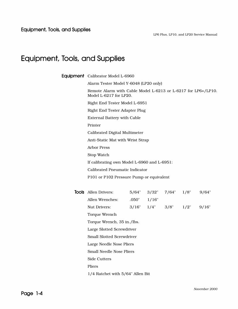
Equipment, Tools, and SuppliesEquipment, Tools, and SuppliesEquipment, Tools, and SuppliesEquipment, Tools, and Supplies
EquipmentEquipmentEquipmentEquipment Calibrator Model L-6960
Alarm Tester Model Y-6048 (LP20 only)
Remote Alarm with Cable Model L-6213 or L-6217 for LP6+/LP10.Model L-6217 for LP20.
Right End Tester Model L-6951
Right End Tester Adapter Plug
External Battery with Cable
Printer
Calibrated Digital Multimeter
Anti-Static Mat with Wrist Strap
Arbor Press
Stop Watch
If calibrating own Model L-6960 and L-6951:
Calibrated Pneumatic Indicator
P101 or P102 Pressure Pump or equivalent
ToolsToolsToolsTools Allen Drivers: 5/64" 3/32" 7/64" 1/8" 9/64"
Allen Wrenches: .050" 1/16"
Nut Drivers: 3/16" 1/4" 3/8" 1/2" 9/16"
Torque Wrench
Torque Wrench, 35 in./lbs.
Large Slotted Screwdriver
Small Slotted Screwdriver
Large Needle Nose Pliers
Small Needle Nose Pliers
Side Cutters
Pliers
1/4 Ratchet with 5/64" Allen Bit
Equipment, Tools, and SuppliesEquipment, Tools, and SuppliesEquipment, Tools, and SuppliesEquipment, Tools, and SuppliesLP6 Plus, LP10, and LP20 Service Manual
November 2000
Page 1-5Page 1-5Page 1-5Page 1-5
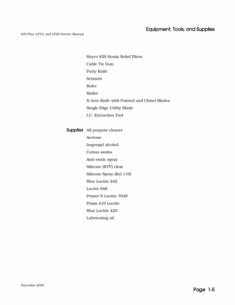
Heyco #29 Strain Relief Pliers
Cable Tie Gun
Putty Knife
Scissors
Ruler
Mallet
X-Acto Knife with Pointed and Chisel Blades
Single Edge Utility Blade
I.C. Extraction Tool
SuppliesSuppliesSuppliesSupplies All purpose cleaner
Acetone
Isopropyl alcohol
Cotton swabs
Anti-static spray
Silicone (RTV) clear
Silicone Spray (Kel 110)
Blue Loctite 242
Loctite 648
Primer N Loctite 7649
Prism 410 Loctite
Blue Loctite 425
Lubricating oil

Equipment, Tools, and SuppliesEquipment, Tools, and SuppliesEquipment, Tools, and SuppliesEquipment, Tools, and SuppliesLP6 Plus, LP10, and LP20 Service Manual
November 2000
Page 1-6Page 1-6Page 1-6Page 1-6
November 2000
Page 2-1Page 2-1Page 2-1Page 2-1
2222 Preventive Preventive Preventive Preventive Maintenance and Maintenance and Maintenance and Maintenance and RecertificationRecertificationRecertificationRecertification
Preventive MaintenancePreventive MaintenancePreventive MaintenancePreventive Maintenance
This process describes the minimum steps necessary to perform a pre-ventive maintenance to the LP6 Plus, LP10, and LP20 Volume Ventila-tors. Reference to other repair processes may be necessary beforeperforming calibration.
FormsFormsFormsForms You must use a copy of the Service Record and Run-In Log found at theend of this manual to document all repairs and testing, and forwardcopies to Nellcor Puritan Bennett.
ProcedureProcedureProcedureProcedure 1.1.1.1. Perform the Check-In Process in Section 3.
2.2.2.2. Replace the internal battery (see Battery Replacement on page 4-1)and the Kapseal, Quadring, and Piston Guides (see Kapseal,Quadring, and Piston Guide Replacement on page 4-3).
3.3.3.3. Perform the Calibration Process on page 3-8.
4.4.4.4. Perform the Reassembly Process on page 3-17.
5.5.5.5. Perform the Run-In Process on page 3-21.
6.6.6.6. Perform the Final Inspection Process on page 3-26.
RecertificationRecertificationRecertificationRecertificationLP6 Plus, LP10, and LP20 Service Manual
November 2000
Page 2-2Page 2-2Page 2-2Page 2-2
RecertificationRecertificationRecertificationRecertification
This process describes the minimum steps necessary to perform arecertification to the LP6 Plus, LP10, and LP20 Volume Ventilators. Ref-erence other repair processes that may be necessary before performingcalibration.
FormsFormsFormsForms You must use a copy of the Service Record and Run-In Log found at theend of this manual to document all repairs and testing, and forwardcopies to Nellcor Puritan Bennett.
ProcedureProcedureProcedureProcedure 1.1.1.1. Perform the Check-In Process on page 3-1.
2.2.2.2. Perform the Calibration Process on page 3-8.
3.3.3.3. Perform the Reassembly Process on page 3-17.
4.4.4.4. Perform the Run-In Process on page 3-21.
5.5.5.5. Perform the Final Inspection Process on page 3-26.
November 2000
Page 3-1Page 3-1Page 3-1Page 3-1
3333 TestingTestingTestingTesting
Check-InCheck-InCheck-InCheck-In
1.1.1.1. Exterior Visual Inspection:
a.a.a.a. Verify that the ventilator’s serial number agrees with theattached paperwork. Verify any notes, etc., that may beattached to the unit.
b.b.b.b. Verify that there is a “J” sticker on the serial number plate ifthe serial number is less than 101132.
Note: If the unit is within the range listed above and it does not have theappropriate sticker, return the unit to Nellcor Puritan Bennett for ser-vice. (Call to verify before returning.)
c.c.c.c. Examine the ventilator for physical abnormalities.
d.d.d.d. Examine the AC power cord for damage. There should not beany cuts through the outer insulation. Pull on the cord, mak-ing sure strain relief holds the cord. Only Nellcor Puritan Ben-nett-authorized power cords and plugs should be on the units.Clean the AC cord. Wrap the AC cord with a large cable tie.
e.e.e.e. Check the unit for loose or missing hardware (e.g. cord wrapfeet).
f.f.f.f. Examine the breaker (ON/OFF) switch for damage. Verify thatis clicks into position.
g.g.g.g. Verify that the serial number plate and all silk screens andlabels are legible. All Warning and Caution labels must be legi-ble and visible. If not readily visible, relocate the labels.
h.h.h.h. Examine the patient airtube screen for damage. Use a flash-light if necessary.
i.i.i.i. Examine the overlays for damage.

Check-InCheck-InCheck-InCheck-InLP6 Plus, LP10, and LP20 Service Manual
November 2000
Page 3-2Page 3-2Page 3-2Page 3-2
j.j.j.j. Verify that the PATIENT PRESSURE meter needle is within onedivision (see Fig. 3-1) of -10 cmH2O/hPa. If it is not, thenremove the meter adjustment hole plug, if provided, andusing a screwdriver, verify that the meter needle can beadjusted above and below -10. Set the meter needle at -10.
Figure 3-1.Figure 3-1.Figure 3-1.Figure 3-1.
2.2.2.2. Cover Removal:
Note: Put on anti-static wrist strap at this point.
a.a.a.a. Verify proper fit of the bottom cover. Remove the four feetfrom the bottom of the ventilator and remove the bottomcover. Write the unit’s serial number on the inside of thebottom cover if working on more than one vent at a time.
b.b.b.b. Verify proper fit of the top and side covers, then remove thetop cover, both side rails and side covers.
c.c.c.c. Remove the filter cap, filter screen, filter, filter screen andO-ring. Alternatively, the unit may have the flatpak filterand retaining ring. If so, remove these and the O-ring. Ifpresent, remove the communication port cover.
d.d.d.d. Remove the High Pressure Relief (HPR) Valve cover.
-10
0
10
20
O ne d iv is ion
O ne d iv is ion
W ith in one d iv is ion o f -10
Check-InCheck-InCheck-InCheck-InLP6 Plus, LP10, and LP20 Service Manual
November 2000
Page 3-3Page 3-3Page 3-3Page 3-3
3.3.3.3. Internal Visual Inspection:
a.a.a.a. Examine the circuit boards for damage by viewing them aswell as possible.
b.b.b.b. Check for liquid in the internal tubing.
c.c.c.c. Check for any other visible damage.
4.4.4.4. Ventilator Operations:
a.a.a.a. Connect a calibrator ribbon cable to the communicationport. Verify that a printer is connected to the calibrator.Verify the 110/220 V switch is set to 110.
b.b.b.b. Connect the ventilator’s power cord to AC, turn the ON/OFFswitch to ON and set the MODEMODEMODEMODE switch to Assist Control;
• Verify proper LED and ALARM operation.
• Set the MODEMODEMODEMODE switch to Standby.
• Verify the front panel AC Power/Batt Charge LED is “on”.
Do not adjust any other settings. Turn the printer on andpress the Battery Test button on the ventilator to generate astatus printout.
Note: Any time the settings change or there is an alarm condition, a print-out is automatically generated every 4 hours.
c.c.c.c. Turn the printer off and remove the printout from theprinter. Compare settings on the printout to the knob set-tings on the front panel.
d.d.d.d. Record hours on the Service Record, top right corner.
Note: Units are required to undergo a Preventive Maintenance at 6,000hours and a recertification annually.
Check-InCheck-InCheck-InCheck-InLP6 Plus, LP10, and LP20 Service Manual
November 2000
Page 3-4Page 3-4Page 3-4Page 3-4
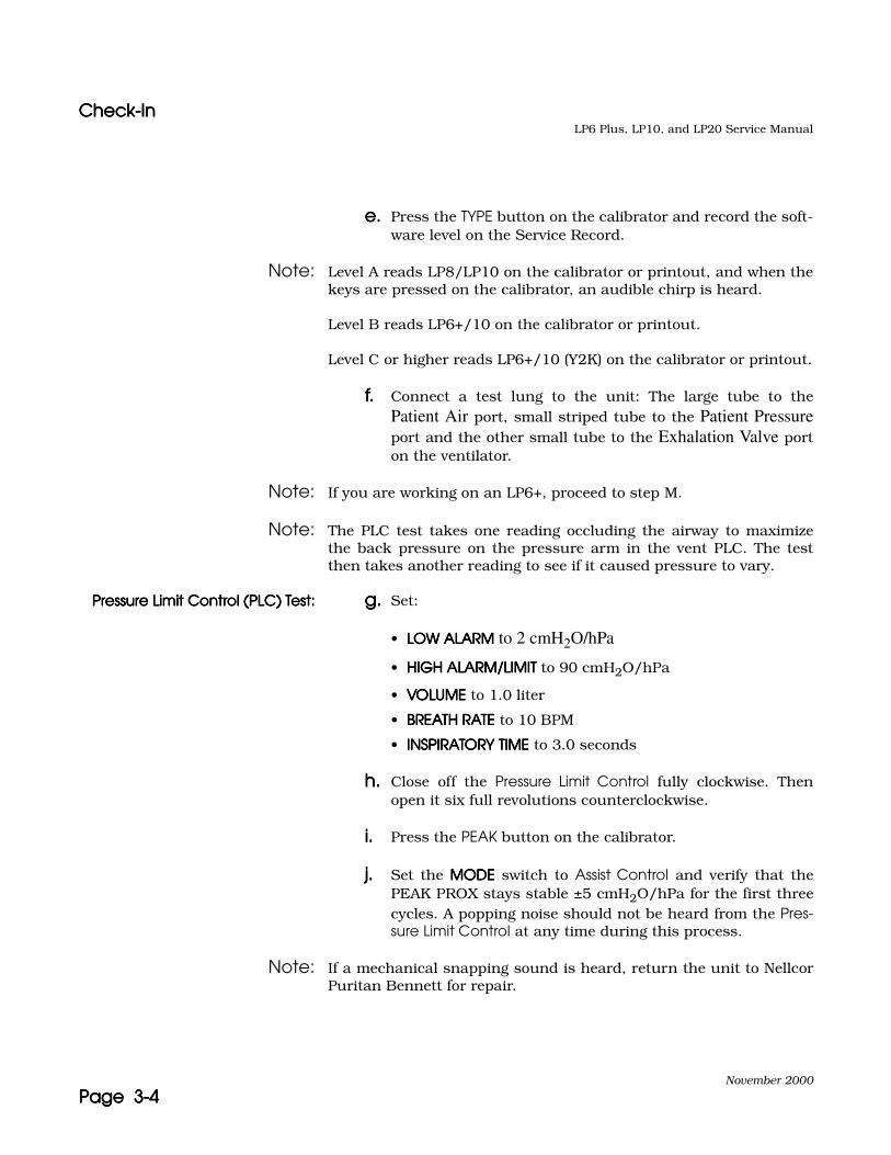
e.e.e.e. Press the TYPE button on the calibrator and record the soft-ware level on the Service Record.
Note: Level A reads LP8/LP10 on the calibrator or printout, and when thekeys are pressed on the calibrator, an audible chirp is heard.
Level B reads LP6+/10 on the calibrator or printout.
Level C or higher reads LP6+/10 (Y2K) on the calibrator or printout.
f.f.f.f. Connect a test lung to the unit: The large tube to thePatient Air port, small striped tube to the Patient Pressureport and the other small tube to the Exhalation Valve porton the ventilator.
Note: If you are working on an LP6+, proceed to step M.
Note: The PLC test takes one reading occluding the airway to maximizethe back pressure on the pressure arm in the vent PLC. The testthen takes another reading to see if it caused pressure to vary.
Pressure Limit Control (PLC) Test:Pressure Limit Control (PLC) Test:Pressure Limit Control (PLC) Test:Pressure Limit Control (PLC) Test: g.g.g.g. Set:
• LOW ALARMLOW ALARMLOW ALARMLOW ALARM to 2 cmH2O/hPa
• HIGH ALARM/LIMITHIGH ALARM/LIMITHIGH ALARM/LIMITHIGH ALARM/LIMIT to 90 cmH2O/hPa
• VOLUMEVOLUMEVOLUMEVOLUME to 1.0 liter
• BREATH RATEBREATH RATEBREATH RATEBREATH RATE to 10 BPM
• INSPIRATORY TIMEINSPIRATORY TIMEINSPIRATORY TIMEINSPIRATORY TIME to 3.0 seconds
h.h.h.h. Close off the Pressure Limit Control fully clockwise. Thenopen it six full revolutions counterclockwise.
i.i.i.i. Press the PEAK button on the calibrator.
j.j.j.j. Set the MODEMODEMODEMODE switch to Assist Control and verify that thePEAK PROX stays stable ±5 cmH2O/hPa for the first threecycles. A popping noise should not be heard from the Pres-sure Limit Control at any time during this process.
Note: If a mechanical snapping sound is heard, return the unit to NellcorPuritan Bennett for repair.
Check-InCheck-InCheck-InCheck-InLP6 Plus, LP10, and LP20 Service Manual
November 2000
Page 3-5Page 3-5Page 3-5Page 3-5
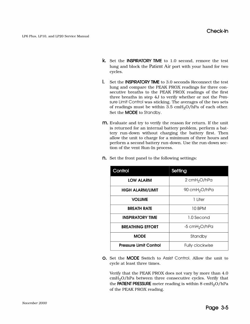
k.k.k.k. Set the INSPIRATORY TIMEINSPIRATORY TIMEINSPIRATORY TIMEINSPIRATORY TIME to 1.0 second, remove the testlung and block the Patient Air port with your hand for twocycles.
l.l.l.l. Set the INSPIRATORY TIMEINSPIRATORY TIMEINSPIRATORY TIMEINSPIRATORY TIME to 3.0 seconds Reconnect the testlung and compare the PEAK PROX readings for three con-secutive breaths to the PEAK PROX readings of the firstthree breaths in step 4J to verify whether or not the Pres-sure Limit Control was sticking. The averages of the two setsof readings must be within 3.5 cmH2O/hPa of each other.Set the MODEMODEMODEMODE to Standby.
m.m.m.m. Evaluate and try to verify the reason for return. If the unitis returned for an internal battery problem, perform a bat-tery run-down without charging the battery first. Thenallow the unit to charge for a minimum of three hours andperform a second battery run-down. Use the run-down sec-tion of the vent Run-In process.
n.n.n.n. Set the front panel to the following settings:
o.o.o.o. Set the MODEMODEMODEMODE Switch to Assist Control. Allow the unit tocycle at least three times.
Verify that the PEAK PROX does not vary by more than 4.0cmH2O/hPa between three consecutive cycles. Verify thatthe PATIENT PRESSUREPATIENT PRESSUREPATIENT PRESSUREPATIENT PRESSURE meter reading is within 8 cmH2O/hPaof the PEAK PROX reading.
ControlControlControlControl SettingSettingSettingSetting
LOW ALARM 2 cmH2O/hPa
HIGH ALARM/LIMIT 90 cmH2O/hPa
VOLUME 1 Liter
BREATH RATE 10 BPM
INSPIRATORY TIME 1.0 Second
BREATHING EFFORT -5 cmH2O/hPa
MODE Standby
Pressure Limit Control Fully clockwise

Check-InCheck-InCheck-InCheck-InLP6 Plus, LP10, and LP20 Service Manual
November 2000
Page 3-6Page 3-6Page 3-6Page 3-6
p.p.p.p. Allow the unit to cycle and check for any other unusualsounds or abnormal operation.
q.q.q.q. Attempt to isolate any problems to the proper assembly. Ifthe problem is verified, note it on the Service Record.
r.r.r.r. Set the MODEMODEMODEMODE switch to Standby and the ON/OFF switch toOFF. Disconnect the unit from AC power. Set the MODEMODEMODEMODEswitch to Assist Control and verify proper start up operationon internal battery. Set the MODEMODEMODEMODE switch to Standby, anddisconnect the calibrator and test lung.
Note: If unit is being recertified only, proceed to Calibration.
Note: There are two types of logic and power/motor boards that have beenused with the LP6+ and LP10: an older through-hole board and anewer surface-mount board. The older through-hole power/motorboard can be easily distinguished by its heat sink. The newer sur-face-mount power/motor board doesn’t need a heat sink. (The LP20has been using only through-hole boards.)
5.5.5.5. Disassembly:
a.a.a.a. Disconnect internal battery from wire harness.
b.b.b.b. Remove the six screws attaching the left end plate.
For LP6+/LP10:
• Disconnect the fan and alarm wires.
• Remove left end plate.
• Verify the ventilator’s serial number is on the left endplate.
For LP20:
• Cut the cable tie securing the remote alarm and thealarm output cables to the external battery circuitbreaker wires.
• Disconnect the remote alarm cable from the Logic Board.
• Disconnect the fan and alarm wires.
Caution Use of anti-static work station and wrist strap is necessary toavoid causing possible damage to the circuit boards.
Check-InCheck-InCheck-InCheck-InLP6 Plus, LP10, and LP20 Service Manual
November 2000
Page 3-7Page 3-7Page 3-7Page 3-7
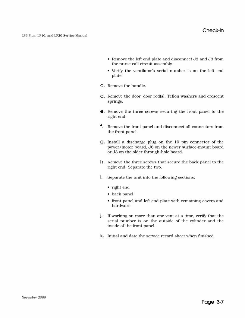
• Remove the left end plate and disconnect J2 and J3 fromthe nurse call circuit assembly.
• Verify the ventilator’s serial number is on the left endplate.
c.c.c.c. Remove the handle.
d.d.d.d. Remove the door, door rod(s), Teflon washers and crescentsprings.
e.e.e.e. Remove the three screws securing the front panel to theright end.
f.f.f.f. Remove the front panel and disconnect all connectors fromthe front panel.
g.g.g.g. Install a discharge plug on the 10 pin connector of thepower/motor board, J6 on the newer surface-mount boardor J3 on the older through-hole board.
h.h.h.h. Remove the three screws that secure the back panel to theright end. Separate the two.
i.i.i.i. Separate the unit into the following sections:
• right end
• back panel
• front panel and left end plate with remaining covers andhardware
j.j.j.j. If working on more than one vent at a time, verify that theserial number is on the outside of the cylinder and theinside of the front panel.
k.k.k.k. Initial and date the service record sheet when finished.

CalibrationCalibrationCalibrationCalibrationLP6 Plus, LP10, and LP20 Service Manual
November 2000
Page 3-8Page 3-8Page 3-8Page 3-8
CalibrationCalibrationCalibrationCalibration
Using the CalibratorUsing the CalibratorUsing the CalibratorUsing the Calibrator • By pressing the CAL button on the calibrator, the first calibra-tion step will appear on the calibrator’s display.
• A description of the calibration step being performed appearson the left and information concerning that step appears onthe right of the calibrator’s display.
• If OK is displayed, and the CAL ERROR LED is not on, that cali-bration step has been successful. You must then press SET torecord the data and advance to the next step. If a number isdisplayed, there has been a problem in that step of calibration,reject the unit.
• If a unit fails any test, repeat the calibration. If the unit stillfails, reject the unit and contact Nellcor Puritan Bennett Tech-nical Service for assistance.
• The SIL button may be used to silence the alarms.
Preliminary Checks and Set-upPreliminary Checks and Set-upPreliminary Checks and Set-upPreliminary Checks and Set-up
1.1.1.1. Back Panel Inspection
a.a.a.a. Verify that the harness wires and ribbon cable are not dam-aged.
b.b.b.b. Verify the internal battery is disconnected from the harnessand the red harness and red or white battery wires areboth on the pointed side of the connectors.
c.c.c.c. Verify the High Pressure Relief screw is tightened.
2.2.2.2. Right End Inspection
a.a.a.a. Verify Motor/Gearbox is secured to the cylinder with fourscrews.
b.b.b.b. Verify that the six cylinder and ten manifold screws areproperly seated.
CautionCautionCautionCaution Use of an anti-static workstation is necessary to perform the fol-lowing process.

CalibrationCalibrationCalibrationCalibrationLP6 Plus, LP10, and LP20 Service Manual
November 2000
Page 3-9Page 3-9Page 3-9Page 3-9
c.c.c.c. Verify the motor wiring assembly is not damaged orpinched between the gearbox and cylinder.
d.d.d.d. Verify three nylon washers and three retaining rings arepresent on the Connecting Rod Assembly.
e.e.e.e. Verify that Loctite is present on all piston feet set screws.
f.f.f.f. Verify Loctite is present on all Crank Arm set screws andthey are properly seated.
3.3.3.3. Front Panel Inspection
a.a.a.a. Verify the correct installation of the overlays.
b.b.b.b. Verify all knobs are correctly aligned and are not loose.
c.c.c.c. Verify the VOLUMEVOLUMEVOLUMEVOLUME and BREATHING EFFORTBREATHING EFFORTBREATHING EFFORTBREATHING EFFORT knobs do notturn without pushing the knobs in first.
d.d.d.d. Verify the meter needle is within one division of -10. If nec-essary, readjust the needle to -10 (MODEMODEMODEMODE switch must beon Standby and the power switch Off).
e.e.e.e. Verify the Patient Air tube screen is not damaged.
f.f.f.f. Verify all pins connecting the Power/Motor and LogicBoards are seated correctly.
g.g.g.g. Verify Display Board ribbon cable is correctly connected.
h.h.h.h. Verify installation and routing of the meter wires.
4.4.4.4. Set-Up
Note: For units which already have the chassis assembled, proceed toStep 7.
a.a.a.a. Fasten the Back Panel to the Right End with the threescrews, if not already done.
b.b.b.b. Remove and inspect the air tube o-ring, apply siliconespray (Kel 110) to air tube with a cotton swab and reinstallthe o-ring. Apply silicone to the o-ring with a cotton swab.

CalibrationCalibrationCalibrationCalibrationLP6 Plus, LP10, and LP20 Service Manual
November 2000
Page 3-10Page 3-10Page 3-10Page 3-10
c.c.c.c. Remove the discharge plug from the Power/Motor Board(J6 on the newer surface-mount board or J3 on the olderthrough-hole board) and connect the 10 pin connector fromthe wire harness.
d.d.d.d. For LP6+/LP10 units, connect the five pin connector fromthe remote alarm jack to the Logic Board (J1 on the newersurface-mount board or J11 on the older through-holeboard).
e.e.e.e. Connect the tubing from the Patient Pressure port to P2 ofthe transducer.
f.f.f.f. Connect the three pin connector from the solenoid to thePower/Motor Board (J1 on the newer surface-mount boardor J7 on the older through-hole board).
g.g.g.g. Connect the 12 pin connector from the stator to the Power/Motor Board (J3 on the newer surface-mount board or J6on the older through-hole board).
Note: New motor/gearbox assemblies feature a ferrite on the 12-pin con-nector housing. If this is used with the older through-hole power/motor board, the ferrite needs to be rotated to miss the heat sink. Ifnot already done, cut the cable tie around the ferrite (not the cabletie around the ferrite and connector housing) and swing the ferritein the opposite direction.
5.5.5.5. Fasten the Front Panel to the Right End with three screws.
6.6.6.6. Set LOW ALARM to 2 cmH2O/hPa and HIGH ALARM/LIMIT to90 cmH2O/hPa.
7.7.7.7. Connect the ribbon cable from the Back Panel to the LogicBoard (J3 on the newer surface-mount board or J10 on theolder through-hole board).
8.8.8.8. Connect a Model L-6960 calibrator to the COMMUNICATIONCOMMUNICATIONCOMMUNICATIONCOMMUNICATIONPORTPORTPORTPORT.
9.9.9.9. Connect the unit to AC power and turn the ventilator’s On/Offswitch to ON. All LED’s should light momentarily except for theAC Pwr/Batt Charge LED, it should remain on.
Note: Allow all changes to stabilize for three seconds before pressing SET.

CalibrationCalibrationCalibrationCalibrationLP6 Plus, LP10, and LP20 Service Manual
November 2000
Page 3-11Page 3-11Page 3-11Page 3-11
10.10.10.10. Press the CAL button on the calibrator to start the first calibra-tion step.
11.11.11.11. Set Date-Time
Use the number pad to enter the date and time-of-day as shown in the example below. (Each bold number is entered, proceeding from left to right.)
SET DATE TIME: 04-22-97 10:22:00
Press the SET key when date and time are correct.
12.12.12.12. EFFORT KNOB = 0 cm
Note: When calibrating BREATHING EFFORTBREATHING EFFORTBREATHING EFFORTBREATHING EFFORT and VOLUMEVOLUMEVOLUMEVOLUME, view knobs fromstraight on.
Carefully, turn the front panel’s BREATHING EFFORTBREATHING EFFORTBREATHING EFFORTBREATHING EFFORT knob to 0.
If OK appears on the display, press the SET button to advance to the next step.
13.13.13.13. EFFORT KNOB = -5 cm
Turn the front panel’s BREATHING EFFORTBREATHING EFFORTBREATHING EFFORTBREATHING EFFORT knob to -5.
If OK appears on the display, press the SET button to advance to the next step.
14.14.14.14. VOLUME KNOB = .2
Turn the VOLUMEVOLUMEVOLUMEVOLUME knob fully counter-clockwise, then set to .2.
If OK appears on the display, press the SET button to advance to the next step.
15.15.15.15. VOLUME KNOB = 1.0
Turn the VOLUMEVOLUMEVOLUMEVOLUME knob clockwise to 1.0.
If OK appears on the display, press the SET button to advance to the next step.
CalibrationCalibrationCalibrationCalibrationLP6 Plus, LP10, and LP20 Service Manual
November 2000
Page 3-12Page 3-12Page 3-12Page 3-12
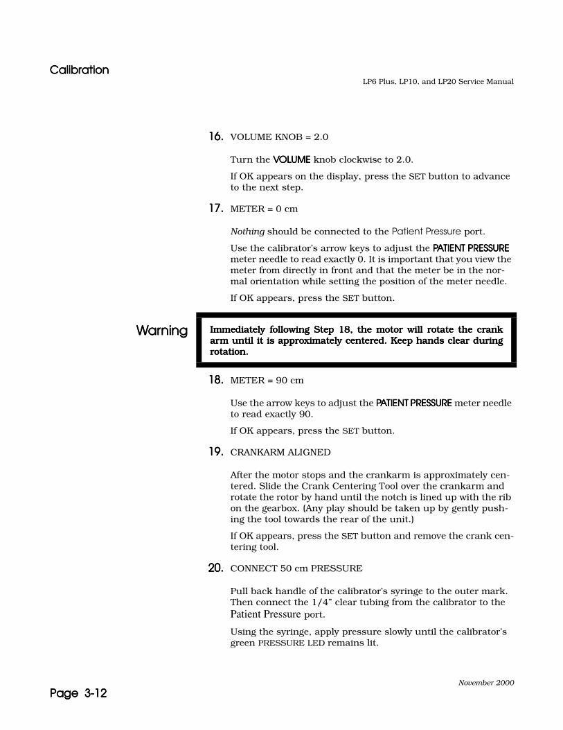
16.16.16.16. VOLUME KNOB = 2.0
Turn the VOLUMEVOLUMEVOLUMEVOLUME knob clockwise to 2.0.
If OK appears on the display, press the SET button to advance to the next step.
17.17.17.17. METER = 0 cm
Nothing should be connected to the Patient Pressure port.
Use the calibrator’s arrow keys to adjust the PATIENT PRESSUREPATIENT PRESSUREPATIENT PRESSUREPATIENT PRESSURE meter needle to read exactly 0. It is important that you view the meter from directly in front and that the meter be in the nor-mal orientation while setting the position of the meter needle.
If OK appears, press the SET button.
18.18.18.18. METER = 90 cm
Use the arrow keys to adjust the PATIENT PRESSUREPATIENT PRESSUREPATIENT PRESSUREPATIENT PRESSURE meter needle to read exactly 90.
If OK appears, press the SET button.
19.19.19.19. CRANKARM ALIGNED
After the motor stops and the crankarm is approximately cen-tered. Slide the Crank Centering Tool over the crankarm and rotate the rotor by hand until the notch is lined up with the rib on the gearbox. (Any play should be taken up by gently push-ing the tool towards the rear of the unit.)
If OK appears, press the SET button and remove the crank cen-tering tool.
20.20.20.20. CONNECT 50 cm PRESSURE
Pull back handle of the calibrator’s syringe to the outer mark. Then connect the 1/4” clear tubing from the calibrator to the Patient Pressure port.
Using the syringe, apply pressure slowly until the calibrator’s green PRESSURE LED remains lit.
WarningWarningWarningWarning Immediately following Step 18, the motor will rotate the crankImmediately following Step 18, the motor will rotate the crankImmediately following Step 18, the motor will rotate the crankImmediately following Step 18, the motor will rotate the crankarm until it is approximately centered. Keep hands clear duringarm until it is approximately centered. Keep hands clear duringarm until it is approximately centered. Keep hands clear duringarm until it is approximately centered. Keep hands clear duringrotation.rotation.rotation.rotation.
CalibrationCalibrationCalibrationCalibrationLP6 Plus, LP10, and LP20 Service Manual
November 2000
Page 3-13Page 3-13Page 3-13Page 3-13
If OK appears, press the SET button. Make sure that the green PRESSURE LED remains lit until the calibrator display changes to the next step.
Remove the tubing from the Patient Pressure port.
Note: Units with the newest surface-mount Power/Motor boards (P/N Y-100116-00B, as combared to the original P/N Y-100116-00A sur-face-mount Power/Motor board) have a different external and inter-nal charge voltage of 14.4 VDC. A newer version of software (Level D)is included with these units which does not light the current LED orthe voltage LED when within the acceptable range during calibra-tion. Instead, only an OK on the display will be used to set thecharge current, and a multimeter will be used to set the charge volt-age during calibration.
21.21.21.21. EXT CURRENT
Verify that the internal battery is disconnected from the har-ness. Connect the calibrator’s external battery connector to the EXTERNAL 12VDCEXTERNAL 12VDCEXTERNAL 12VDCEXTERNAL 12VDC receptacle on the back panel of the ventilator. Press and hold the CHARGE button on the calibrator.
If the OK appears on the display, press the SET button on the calibrator and hold the CHARGE button down until the display has changed to the next step.
22.22.22.22. EXT VOLTS
a.a.a.a. With the calibrator’s external battery connector stillattached to the back panel, connect a digital multimeter tothe calibrator’s internal battery connector.
b.b.b.b. If necessary, adjust the Trim Pot on the Power/Motor boardwith a plastic screwdriver:
• For any through-hole Power/Motor board, adjust theR60 until the voltage reads 13.80 ±.05 VDC on the multi-meter.
• For a surface-mount Power/Motor board with softwareVersion C (can be identified by pressing the TYPE buttonon the calibrator) or P/N Y-100116-00A (can be identifiedby the label on the board), adjust the R108 until the volt-age reads 13.80 ±.05 VDC on the multimeter.
Caution Do not hold the CHARGE button for more than ten seconds.
CalibrationCalibrationCalibrationCalibrationLP6 Plus, LP10, and LP20 Service Manual
November 2000
Page 3-14Page 3-14Page 3-14Page 3-14
• For a surface-mount Power/Motor board with P/N Y-100116-00B or higher (can be identified by the label onthe board), adjust the R108 until the voltage reads 14.40±.05 VDC on the multimeter.
Note: The software version should not be used to determine if the chargevoltage should be 14.4V because a 13.8V Power/Motor board canpossibly have a logic board with the version D software.
c.c.c.c. If OK appears on the display, press the SET button on thecalibrator.
d.d.d.d. If an error code appears, reject the unit.
e.e.e.e. Disconnect the external battery connector from the back ofthe ventilator.
f.f.f.f. Disconnect the multimeter from the calibrator’s internalbattery connector.
23.23.23.23. INT CURRENT
Connect the calibrator’s two-pin internal battery connector to the plug for the battery in the harness. Press and hold the CHARGE button.
If OK appears on the display, press the SET button on the cali-brator and hold the CHARGE button down until the display has changed to the next step.
24.24.24.24. INT VOLTS
a.a.a.a. With the calibrator’s internal battery connector stillattached to the harness, connect the multimeter to the cal-ibrator’s external battery connector.
b.b.b.b. If necessary, adjust the Trim Pot on the Power/Motor boardwith a plastic screwdriver:
• For any through-hole Power/Motor board, adjust theR60 until the voltage reads 13.80 ±.05 VDC on the multi-meter.
• For a surface-mount Power/Motor board with software
Caution Do not hold the CHARGE button for more than ten seconds.

CalibrationCalibrationCalibrationCalibrationLP6 Plus, LP10, and LP20 Service Manual
November 2000
Page 3-15Page 3-15Page 3-15Page 3-15
Version C (can be identified by pressing the TYPE buttonon the calibrator) or P/N Y-100116-00A (can be identifiedby the label on the board), adjust the R108 until the volt-age reads 13.80 ±.05 VDC on the multimeter.
• For a surface-mount Power/Motor board with P/N Y-100116-00B or higher (can be identified by the label onthe board), adjust the R108 until the voltage reads 14.40±.05 VDC on the multimeter.
Note: The software version should not be used to determine if the chargevoltage should be 14.4V because a 13.8V Power/Motor board canpossibly have a logic board with the version D software.
c.c.c.c. If OK appears on the display, press the SET button on thecalibrator.
d.d.d.d. If an error code appears, reject the unit.
e.e.e.e. Disconnect the calibrator from the internal battery har-ness. Reconnect the ventilator’s internal battery into theharness.
f.f.f.f. Disconnect the multimeter from the calibrator’s externalbattery connector.
25.25.25.25. SET SERIAL NUMBER = XXXXXX
Verify serial number on the calibrator’s display matches serial number of the unit. If correct press SET. If not correct, verify that it is the correct front panel for the ventilator and enter the unit’s serial number and press SET.
26.26.26.26. RESET MACHINE HOURS HOURS NOW = XXXXX
Note: If hours have already been reset or a Preventive Maintenance hasnot been performed, proceed to Step 27.
If a Preventive Maintenance has been performed and hours have notbeen reset, press SET.
27.27.27.27. Turn the ventilator OFF.

CalibrationCalibrationCalibrationCalibrationLP6 Plus, LP10, and LP20 Service Manual
November 2000
Page 3-16Page 3-16Page 3-16Page 3-16
28.28.28.28. Set the front panel as follows:
29.29.29.29. Leak Check
a.a.a.a. Turn the ventilators ON/OFF switch to ON.
b.b.b.b. Ensure the High Pressure Relief screw is tightened.
c.c.c.c. With the calibrator still hooked up, set MODEMODEMODEMODE to Assist Con-trol. Allow the ventilator to retract and pause. Attach agreen test plug with adapter to the ventilator and block thesmall vent hole on the green test plug. The motor must stallor move very slowly.
30.30.30.30. High Pressure Relief (HPR) Calibration
a.a.a.a. Press the PEAK button on the calibrator. Allow reading tostabilize. Reading must be greater than 120 cmH2O/hPa.
b.b.b.b. Adjust the High Pressure Relief screw until the PEAK PROXPRESS is between 100 and 110 cmH2O/hPa. The PATIENTPATIENTPATIENTPATIENTPRESSUREPRESSUREPRESSUREPRESSURE meter must peak greater than 100.
31.31.31.31. Set MODEMODEMODEMODE to Standby.
32.32.32.32. Turn the unit OFF and disconnect the calibrator and green testplug with adaptor.
33.33.33.33. Disconnect the unit from AC power.
34.34.34.34. Passed units are ready for reassembly.
ControlControlControlControl SettingSettingSettingSetting
MODE Standby
LOW ALARM 2 cmH2O/hPa
HIGH ALARM/LIMIT 90 cmH2O/hPa
VOLUME 1.0 Liter
BREATH RATE 10 BPM
INSPIRATORY TIME 1.0 Second
BREATHING EFFORT approximately -5 cmH2O/hPa
Pressure Limit Control(LP10/LP20 only)
Fully Clockwise

ReassemblyReassemblyReassemblyReassemblyLP6 Plus, LP10, and LP20 Service Manual
November 2000
Page 3-17Page 3-17Page 3-17Page 3-17
ReassemblyReassemblyReassemblyReassembly
1.1.1.1. Verify the following:
a.a.a.a. Harness wires and ribbon cable are not pinched.
b.b.b.b. Unit serial number matches the paperwork.
c.c.c.c. Motor/Gearbox wiring is routed correctly and is notpinched.
d.d.d.d. Meter wires are routed correctly.
e.e.e.e. Solenoid wires are routed correctly.
f.f.f.f. All connectors and internal tubing are properly connected.
2.2.2.2. Locate the correct assembly parts for the unit being assembled.
Note: For units which already have the chassis assembled, proceed to step12.
3.3.3.3. Set the ventilator on its right side.
4.4.4.4. Install, on the right end of the door rod, a Teflon washer and acrescent spring, pointed ends of the crescent spring towardsthe Teflon washer.
5.5.5.5. Insert the right end of door rod into the front panel bezel andclose door onto the front panel striker plate.
6.6.6.6. Install, on the left end of the door rod, a Teflon washer and acrescent spring, pointed ends of the crescent spring towardsthe Teflon washer.
7.7.7.7. Orient handle with flat side away from front panel and moldmark down. Insert handle into right end plate assembly.
8.8.8.8. Position left end plate to front and back panels. If necessary,reposition harness wires to keep wires from being pinched ordamaged.
9.9.9.9. For LP20 connect J2 to P2 and J3 to P3 on the nurse call cir-cuit assembly and using a cable tie, bundle the two cables con-

ReassemblyReassemblyReassemblyReassemblyLP6 Plus, LP10, and LP20 Service Manual
November 2000
Page 3-18Page 3-18Page 3-18Page 3-18
nected to P2 and P3 on the nurse call circuit assembly to theblue wire from the DC breaker and the brown wire from thewire harness.
10.10.10.10. Connect the following:
Note: • For LP6+/LP10 with the older through-hole power/motorboard, route the wires as shown in Figure 3.2
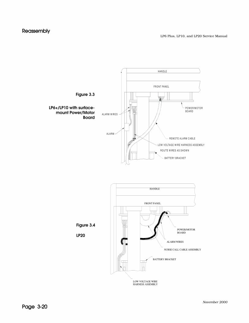
• For LP6+/LP10 with the newer surface-mount power/motorboard, route the wires as shown in Figure 3.3
• For LP20, route the wire as shown in Figure 3.4.
a.a.a.a. If the older through-hole power/motor board is used,attach the fan assembly connector to J8. If the newer sur-face-mount power/motor board is used, a fan is not neces-sary.
b.b.b.b. If the newer surface-mount power/motor board is used,attach the alarm connector to J7 on the board. If the olderthrough-hole power/motor board is used, connect thealarm wires (red wire to the (+) terminal).
c.c.c.c. For LP20 units, connect the five pin connector from thenurse call circuit assembly, P11, to the Logic Board.
11.11.11.11. Fasten the left end plate to the front and back panels with sixscrews.
12.12.12.12. Install:
• High Pressure Relief valve cover
If standard inlet filter is used:
• O-ring
• Filter support screen
• Filter
• Filter support screen
• Filter cap, hand tightened
If Flatpak inlet filter is used:
• O-ring
• Flatpak filter
• Retainer ring, hand-tightened

ReassemblyReassemblyReassemblyReassemblyLP6 Plus, LP10, and LP20 Service Manual
November 2000
Page 3-19Page 3-19Page 3-19Page 3-19
13.13.13.13. Secure the 1/4” tubing on the transducer with a cable tie. Ver-ify that the tubing is not kinked.
14.14.14.14. Position one side rail on the left side cover and fasten to the leftside of unit with two screws.
15.15.15.15. Position one side rail on the right side cover and fasten to theright side of unit with two screws.
16.16.16.16. Install a top cover, and retainer, if needed. Secure with twoscrews, hand tightened.
17.17.17.17. Install the bottom cover and four bottom feet.
18.18.18.18. Passed units are ready for Run-In.
LOW VOLTAGE WIRE HARNESS ASSEMBLY
REMOTE ALARM CABLE ASSEMBLY
ALARM WIRES
FRONT PANEL
HANDLE
POWER/MOTORBOARD
Figure 3.2
LP6+/LP10 with through-hole Power/Motor Board
ReassemblyReassemblyReassemblyReassemblyLP6 Plus, LP10, and LP20 Service Manual
November 2000
Page 3-20Page 3-20Page 3-20Page 3-20
Figure 3.3
H A N D L E
F R O N T PA N E L
P O W E R /M O TO R B O A R D
A LA R M W IR E S
L O W V O LTA G E W IR E H A R N E S S A S S E M B LY
R O U T E W IR E S A S S H O W N
R E M O T E A L A R M C A B L E
B AT T E R Y B R A C K E T
A LA R M
LP6+/LP10 with surface-mount Power/Motor
Board
HARNESS ASSEMBLYLOW VOLTAGE WIRE
NURSE CALL CABLE ASSEMBLY
POWER/MOTOR
BATTERY BRACKET
FRONT PANEL
ALARM WIRES
BOARD
HANDLE
Figure 3.4
LP20

Run-inRun-inRun-inRun-inLP6 Plus, LP10, and LP20 Service Manual
November 2000
Page 3-21Page 3-21Page 3-21Page 3-21
Run-inRun-inRun-inRun-in
Before beginning the Run-In process, make a copy of Run-In LogSheet located in the back of this manual.
Note: Reject the unit if one or more of the following conditions occur:
• Fails to cycle or cycles erratically
• Exhibits any abnormal mechanical noise
• Produces unexpected alarms
• Generates incorrect printouts
• Does not pass battery run down
• The unit does not respond correctly to any condition explainedin the Run-In process.
1.1.1.1. Plug ventilator into AC power. Turn power switch on. Verify thepressure limit control is turned fully clockwise, do not over-tighten.
2.2.2.2. Set front panel to Adult Run parameters as follows:
•LOW ALARMLOW ALARMLOW ALARMLOW ALARM= Minimum•HIGH ALARM LIMITHIGH ALARM LIMITHIGH ALARM LIMITHIGH ALARM LIMIT= Maximum•VOLUMEVOLUMEVOLUMEVOLUME= 1.0 liters•BREATH RATEBREATH RATEBREATH RATEBREATH RATE= 16 BPM•INSPIRATORY TIMEINSPIRATORY TIMEINSPIRATORY TIMEINSPIRATORY TIME= 1.5 second•BREATHING EFFORTBREATHING EFFORTBREATHING EFFORTBREATHING EFFORT= -5 cmH2O
•MODEMODEMODEMODE= STANDBY
3.3.3.3. Connect RED run-in plug, with silicone connector to the venti-lator. Turn MODEMODEMODEMODE switch to ASSIST/CONTROL. Reset anyalarms.
4.4.4.4. Record serial number, Adult Run start date and time on Run-In Log sheet. Allow unit to run for a minimum of 2 hours. Ver-ify no alarms.

Run-inRun-inRun-inRun-inLP6 Plus, LP10, and LP20 Service Manual
November 2000
Page 3-22Page 3-22Page 3-22Page 3-22
5.5.5.5. Attach printer to the ventilator, turn printer on and initiate aprintout.
For the SET parameters on all printouts:
The Mode, Breath Rate, Inspiratory Time, Low Alarm and High Alarm/Limit must all be exact setting values.
• The volume must be .980 – 1.020 liters.
• The breathing effort must be –4.5 to –5.5 cmH2O/hPa.
If the date or time on the printout is not correct, connect a cal-ibrator to the COMMUNICATION PORT and enter in the correct date and time using the following steps:
a.a.a.a. Press the CAL button on the calibrator.
b.b.b.b. Enter the correct date and time using the number pad.
c.c.c.c. Press the SET button.
6.6.6.6. Unplug the AC power cord of the ventilator.
7.7.7.7. Verify:
• Printout automatically generated. Printout must say“Alarms: Power Switchover”.
• POWER SWITCHOVER alarm sounds and corresponding alarmLED illuminates.
• Ventilator continues to run on internal battery.
• Internal battery LED flashes.
• No interrupted operation of flow occurs to patient ports.
8.8.8.8. Press ALARM SILENCE/RESETALARM SILENCE/RESETALARM SILENCE/RESETALARM SILENCE/RESET button to reset the Power Switcho-ver alarm condition.
9.9.9.9. Allow unit to run on internal battery. Verify when next alarmsounds and that following conditions occur:
• Verify LOW POWER LED lights and the alarm sounds.
• Printout automatically generated.
• Verify that the ventilator ran at least 45 minutes on internalbattery before switching to a low power condition. (Write theactual time on the Run-In Log sheet.) If printout states 99min., verify actual time.
• Verify unit functioning properly.
Run-inRun-inRun-inRun-inLP6 Plus, LP10, and LP20 Service Manual
November 2000
Page 3-23Page 3-23Page 3-23Page 3-23
10.10.10.10. You may silence the alarm with the calibrator if one is present.
11.11.11.11. Verify third printout generated automatically 15 minutes later.Verify proper operation.
12.12.12.12. Connect ventilator to AC power or set back panel on/offbreaker to the “On” position and disconnect printer from venti-lator. Reset any alarms.
Note: If at least one of the printed circuit boards has been replaced duringservicing, go to step 18.
13.13.13.13. Allow the ventilator to run until the total hours of the Run-In isa minimum of 20 hours.
14.14.14.14. Verify the unit has run for a total of 20 hours minimum.
15.15.15.15. Set the MODEMODEMODEMODE to Standby and the On/OffOn/OffOn/OffOn/Off switch to Off. Discon-nect the RED run-in plug. Unplug the unit from AC power.
16.16.16.16. Record Adult Rate Run end date and time on Run-In Log sheet.
17.17.17.17. Passed units are ready for Initial Inspection.
Note: The following steps are only for ventilators where at least one of theprinted circuit boards has been replaced during servicing.
18.18.18.18. Run ventilator for approximately 5 minutes and disconnectunit from AC power momentarily. Verify unit switched to inter-nal battery and is operating normally. Reset alarm and restoreAC power to ventilator.
19.19.19.19. Turn MODEMODEMODEMODE switch to STANDBY and disconnect RED run-inplug, with silicone connector.
20.20.20.20. Record Adult Rate Run end date and time on Run-In Log sheet.

Run-inRun-inRun-inRun-inLP6 Plus, LP10, and LP20 Service Manual
November 2000
Page 3-24Page 3-24Page 3-24Page 3-24
21.21.21.21. Set front panel to High Rate RunHigh Rate RunHigh Rate RunHigh Rate Run as follows:
• LOW ALARMLOW ALARMLOW ALARMLOW ALARM = Minimum
• HIGH ALARM LIMITHIGH ALARM LIMITHIGH ALARM LIMITHIGH ALARM LIMIT = Maximum
• VOLUMEVOLUMEVOLUMEVOLUME = Minimum
• BREATH RATEBREATH RATEBREATH RATEBREATH RATE = 38 BPM
• INSPIRATORY TIMEINSPIRATORY TIMEINSPIRATORY TIMEINSPIRATORY TIME = 0.5 seconds
• BREATHING EFFORTBREATHING EFFORTBREATHING EFFORTBREATHING EFFORT = -5 cmH2O
• MODEMODEMODEMODE = STANDBY
22.22.22.22. Connect GREEN run-in plug, with silicone connector to theventilator. Turn MODEMODEMODEMODE switch to ASSIST/CONTROL. Reset anyalarms.
23.23.23.23. Record High Rate Run start date and time on Run-In Logsheet.
24.24.24.24. Allow unit to run on above settings for minimum 2 hours. Ver-ify no alarms occur.
25.25.25.25. Turn MODEMODEMODEMODE switch fully to STANDBY and remove GREEN run-in plug.
26.26.26.26. Record High Rate Run end date and time on Run-In Log sheet.
27.27.27.27. Set front panel to Max Volume Run parameters as follows:
• LOW ALARMLOW ALARMLOW ALARMLOW ALARM = Minimum
• HIGH ALARM LIMITHIGH ALARM LIMITHIGH ALARM LIMITHIGH ALARM LIMIT = Maximum
• VOLUMEVOLUMEVOLUMEVOLUME = Maximum (2.2 liter)
• BREATH RATEBREATH RATEBREATH RATEBREATH RATE = 7 BPM
• INSPIRATORY TIMEINSPIRATORY TIMEINSPIRATORY TIMEINSPIRATORY TIME = 2.5 seconds
• BREATHING EFFORTBREATHING EFFORTBREATHING EFFORTBREATHING EFFORT = +5 cmH2O
• MODEMODEMODEMODE = STANDBY
28.28.28.28. Connect RED run-in plug, with silicone connector, to the venti-lator. Turn MODEMODEMODEMODE to ASSIST/CONTROL. Reset any alarms.
29.29.29.29. Record Max Volume Run start date and time on Run-In Logsheet.

Run-inRun-inRun-inRun-inLP6 Plus, LP10, and LP20 Service Manual
November 2000
Page 3-25Page 3-25Page 3-25Page 3-25
30.30.30.30. Allow unit to run on above settings for minimum 9 hours.
31.31.31.31. Run unit for a few breaths. Disconnect unit from AC powermomentarily. Verify unit switched to internal battery and isoperating normally. Reset alarm and restore AC power to unit.
32.32.32.32. Run unit for a minimum of one minute. Disconnect unit fromAC power momentarily. Verify unit switched to internal batteryand is operating normally. Reset alarm and restore AC powerto unit.
33.33.33.33. Verify unit has run for minimum 20 hours.
34.34.34.34. Set MODEMODEMODEMODE to STANDBY and the On/OffOn/OffOn/OffOn/Off switch to Off. Disconnectthe RED run-in plug. Unplug the unit from AC power.
35.35.35.35. Record Max Volume Run end date and time on run-in logsheet.
36.36.36.36. Passed units are ready for Final Inspection.

Final InspectionFinal InspectionFinal InspectionFinal InspectionLP6 Plus, LP10, and LP20 Service Manual
November 2000
Page 3-26Page 3-26Page 3-26Page 3-26
Final InspectionFinal InspectionFinal InspectionFinal Inspection
The purpose of this process is to specify the test and parameters toinspect the ventilator. Use the Service Record when completing thisprocess.
Note: If any calibration needs to be performed, repeat Calibration, Run-In,and Final Inspection.
Mark Pass/Fail on the Service Record while performing the finalinspection.
Visual ChecksVisual ChecksVisual ChecksVisual Checks 1.1.1.1. Visually examine the ventilator for abnormalities.
2.2.2.2. Verify all knobs are:
• turned fully counter-clockwise (Pressure Limit Control fullyclockwise)
• tight
• within a line’s width of all panel markings
Note: The white pointer on the knob must be fully within the dashed linesas shown in Figures 3.5, 3.6, and 3.7 (i.e., the white pointer shouldcover some portion of the panel marking.
3.3.3.3. Verify the PATIENT PRESSUREPATIENT PRESSUREPATIENT PRESSUREPATIENT PRESSURE meter is within one division of -10.

Final InspectionFinal InspectionFinal InspectionFinal InspectionLP6 Plus, LP10, and LP20 Service Manual
November 2000
Page 3-27Page 3-27Page 3-27Page 3-27
ControlsControlsControlsControls
Note: Use Model L-6213 or L-6217 remote alarm for LP6+/LP10. UseModel L-6217 remote alarm for LP20.
1.1.1.1. Connect the following:
• LP6 Plus/LP10 Calibrator ribbon cable to the communica-tions port
• remote alarm to remote alarm jack
• ventilator power cord to AC
2.2.2.2. Set the On/Off switch to ON.
Note: Make sure that the printer is not connected at this point.
3.3.3.3. Press the calibrator’s BPM key. Verify all positions of BREATHBREATHBREATHBREATHRATE RATE RATE RATE switch on the calibrator display (left number).
4.4.4.4. Press the calibrator’s INS key. Verify all positions of INSPIRA-INSPIRA-INSPIRA-INSPIRA-TORY TIMETORY TIMETORY TIMETORY TIME switch.
5.5.5.5. Press the calibrator’s ALARM key, then NEXT key twice. Verifyall positions of MODEMODEMODEMODE switch. Alarms should occur. ReturnMODEMODEMODEMODE to Standby.
6.6.6.6. Press NEXT key. Verify all positions of HIGH ALARM/LIMITHIGH ALARM/LIMITHIGH ALARM/LIMITHIGH ALARM/LIMITswitch.
2
6
4
810
161412
32
28
30
2624
18
2220
LOW ALARM
Linewidth
Line width
Within a line's width
Figure 3.5 Figure 3.6 Figure 3.7
Final InspectionFinal InspectionFinal InspectionFinal InspectionLP6 Plus, LP10, and LP20 Service Manual
November 2000
Page 3-28Page 3-28Page 3-28Page 3-28
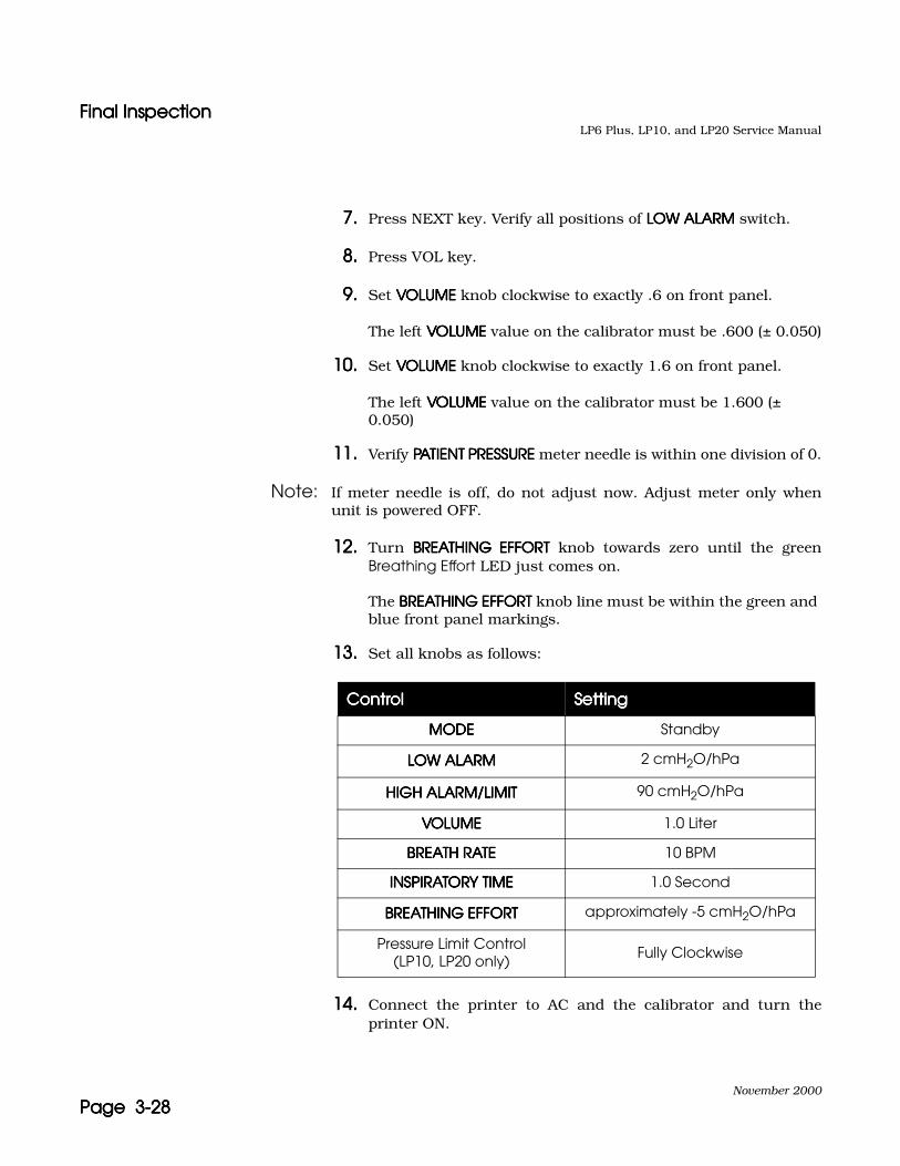
7.7.7.7. Press NEXT key. Verify all positions of LOW ALARMLOW ALARMLOW ALARMLOW ALARM switch.
8.8.8.8. Press VOL key.
9.9.9.9. Set VOLUMEVOLUMEVOLUMEVOLUME knob clockwise to exactly .6 on front panel.
The left VOLUMEVOLUMEVOLUMEVOLUME value on the calibrator must be .600 (± 0.050)
10.10.10.10. Set VOLUMEVOLUMEVOLUMEVOLUME knob clockwise to exactly 1.6 on front panel.
The left VOLUMEVOLUMEVOLUMEVOLUME value on the calibrator must be 1.600 (± 0.050)
11.11.11.11. Verify PATIENT PRESSUREPATIENT PRESSUREPATIENT PRESSUREPATIENT PRESSURE meter needle is within one division of 0.
Note: If meter needle is off, do not adjust now. Adjust meter only whenunit is powered OFF.
12.12.12.12. Turn BREATHING EFFORTBREATHING EFFORTBREATHING EFFORTBREATHING EFFORT knob towards zero until the greenBreathing Effort LED just comes on.
The BREATHING EFFORTBREATHING EFFORTBREATHING EFFORTBREATHING EFFORT knob line must be within the green and blue front panel markings.
13.13.13.13. Set all knobs as follows:
14.14.14.14. Connect the printer to AC and the calibrator and turn theprinter ON.
ControlControlControlControl SettingSettingSettingSetting
MODEMODEMODEMODE Standby
LOW ALARMLOW ALARMLOW ALARMLOW ALARM 2 cmH2O/hPa
HIGH ALARM/LIMITHIGH ALARM/LIMITHIGH ALARM/LIMITHIGH ALARM/LIMIT 90 cmH2O/hPa
VOLUMEVOLUMEVOLUMEVOLUME 1.0 Liter
BREATH RATEBREATH RATEBREATH RATEBREATH RATE 10 BPM
INSPIRATORY TIMEINSPIRATORY TIMEINSPIRATORY TIMEINSPIRATORY TIME 1.0 Second
BREATHING EFFORTBREATHING EFFORTBREATHING EFFORTBREATHING EFFORT approximately -5 cmH2O/hPa
Pressure Limit Control(LP10, LP20 only)
Fully Clockwise
Final InspectionFinal InspectionFinal InspectionFinal InspectionLP6 Plus, LP10, and LP20 Service Manual
November 2000
Page 3-29Page 3-29Page 3-29Page 3-29
15.15.15.15. Attach the red test plug to the ventilator and set MODEMODEMODEMODE to AssistControl.
The printer will print a status printout.
16.16.16.16. After the printer stops printing, turn printer off and removeprintout.
17.17.17.17. On the printout verify serial number of the unit, HOURS,DATE, and TIME are correct.
18.18.18.18. Using a stop watch, verify that the cycle time is 6 ± 1 seconds.
Start the stop watch at the beginning of the the cycle, then stop at the beginning of the next cycle.
Alarm CheckAlarm CheckAlarm CheckAlarm Check 1.1.1.1. For LP6+/LP10 ventilators performing the following:
Press the Alarm Silence/Reset button. Verify that all LEDs light and an alarm sounds, then all LEDs turn off except the AC Pwr/Batt Charge LED.
2.2.2.2. For LP20 ventilators perform the following:
Note: Two types of alarm sound patterns exist for the LP20; a steady on/off pulsing alarm, and a dual pulse alarm. When verification of anaudible alarm is necessary, assume the steady on/off type isrequired unless otherwise noted.
Press and hold down the Alarm Silence/Reset button for three seconds or longer. Verify that:
• Setting Error/Presilence LED lights continuously
• All other LEDs light momentarily.
• The alarm sounds momentarily.
• Only the AC Pwr/Batt Charge LED stays lit.
3.3.3.3. Turn remote alarm on and set High Alarm/Limit Switch of ven-tilator to 15 cmH2O/hPa. High Pressure LED on ventilator andAlarm LED on remote alarm must flash and alarm must soundon ventilator and remote alarm within two cycles.
4.4.4.4. Set High Alarm/Limit Switch to 90 cmH2O/hPa. Press AlarmSilence/Reset button on ventilator to reset the alarm.
Final InspectionFinal InspectionFinal InspectionFinal InspectionLP6 Plus, LP10, and LP20 Service Manual
November 2000
Page 3-30Page 3-30Page 3-30Page 3-30
5.5.5.5. Disconnect the Patient Pressure tubing from the ventilator. LowPressure/Apnea LED on ventilator and ALARM LED on remotealarm must flash and alarm must sound on ventilator andremote alarm within several cycles. (For LP20 verify audiblealarm on ventilator and remote alarm is a dual pulse alarm.)
6.6.6.6. Re-connect the Patient Pressure tubing to the ventilator andpress RESET button on remote alarm.
7.7.7.7. Set MODEMODEMODEMODE to Standby. The remote alarm must sound an audi-ble alarm and ALARM LED must flash.
8.8.8.8. Turn remote alarm OFF and disconnect from ventilator.
Alarm Output Test (LP20 only)Alarm Output Test (LP20 only)Alarm Output Test (LP20 only)Alarm Output Test (LP20 only) 1.1.1.1. Set On/Off switch OFF then back to ON.
2.2.2.2. Connect the 1/4” phono plug on the Alarm Tester Model Y-6048 to the ALARM OUTPUTALARM OUTPUTALARM OUTPUTALARM OUTPUT jack of the ventilator. Connect adigital multimeter to the tester (red wire to positive (+), blackwire to negative (-). Set the multimeter to VDC.
3.3.3.3. Set the selection knob to BATTERY CHECK. Verify that the dis-played voltage is >8 VDC.
4.4.4.4. Set the selection knob to NURSE CALL. Set the voltmeter toohms.
• If the digital multimeter reads greater than 1.0 megohms, goto step 5.
• If the digital multimeter reads less than 1.0 ohm, go to step12.
5.5.5.5. Disconnect the multimeter leads from the alarm tester. Set theselection knob to ALARM TEST.
6.6.6.6. Set the MODEMODEMODEMODE to Assist Control.
7.7.7.7. Set the HIGH ALARM/LIMITHIGH ALARM/LIMITHIGH ALARM/LIMITHIGH ALARM/LIMIT to 15. Within several breaths, verifythe LED on the alarm tester is lit continuously as the High Pres-sure LED lights and an audible alarm sounds.
8.8.8.8. Set the HIGH ALARM/LIMITHIGH ALARM/LIMITHIGH ALARM/LIMITHIGH ALARM/LIMIT to 90. Press Alarm Silence/Reset.
9.9.9.9. Disconnect the Patient Pressure Tubing from the ventilator.
Final InspectionFinal InspectionFinal InspectionFinal InspectionLP6 Plus, LP10, and LP20 Service Manual
November 2000
Page 3-31Page 3-31Page 3-31Page 3-31
10.10.10.10. Within several breaths, verify the Low Pressure/Apnea LED islit and a dual pulsing alarm is generated along with a corre-sponding flashing of the alarm tester LED.
11.11.11.11. Reconnect the Patient Pressure Tubing. Press Alarm Silence/Reset. Proceed to step 19.
12.12.12.12. Disconnect the multimeter leads from the alarm tester. Set theselection knob to ALARM TEST.
13.13.13.13. Set the MODEMODEMODEMODE to Assist Control. Verify LED on alarm tester is lit.
14.14.14.14. Set the HIGH ALARM/LIMITHIGH ALARM/LIMITHIGH ALARM/LIMITHIGH ALARM/LIMIT to 15. Within several breaths, verifythat the LED on the alarm tester turns off as the High PressureLED lights and an audible alarm sounds.
15.15.15.15. Set the HIGH ALARM/LIMITHIGH ALARM/LIMITHIGH ALARM/LIMITHIGH ALARM/LIMIT to 90. Press Alarm Silence/Reset.Verify that the LED on the alarm tester lights.
16.16.16.16. Disconnect the Patient Pressure Tubing from the ventilator.
17.17.17.17. Within several breaths, verify that the Low Pressure/ApneaLED is lit and a dual pulsing alarm is generated along with acorresponding flashing of the alarm tester LED.
18.18.18.18. Reconnect the Patient Pressure Tubing. Press Alarm Silence/Reset.
19.19.19.19. Set the alarm tester to SUPPLY and disconnect it from the ven-tilator.
20.20.20.20. Start the stopwatch while momentarily pressing Alarm Silence/Reset. Verify the Setting Error/Presilence LED lights continu-ously.
21.21.21.21. Set the INSPIRATORY TIMEINSPIRATORY TIMEINSPIRATORY TIMEINSPIRATORY TIME to 4.0. The Setting Error/PresilenceLED should start flashing, with no audible alarm.
22.22.22.22. Disconnect the Patient Pressure Tubing from the ventilator.Within several breaths, verify the Low Pressure/Apnea LEDstarts flashing along with the Setting Error/Presilence LED, withno audible alarm.
23.23.23.23. Stop the stopwatch upon hearing a dual pulse alarm. Verify thestopwatch reads 60.0 ± 2.0 seconds.

Final InspectionFinal InspectionFinal InspectionFinal InspectionLP6 Plus, LP10, and LP20 Service Manual
November 2000
Page 3-32Page 3-32Page 3-32Page 3-32
24.24.24.24. Reconnect the Patient Pressure Tubing to the ventilator. Verifythe audible dual pulse alarm changes to a steady on/off puls-ing alarm within several seconds.
25.25.25.25. Set the INSPIRATORY TIMEINSPIRATORY TIMEINSPIRATORY TIMEINSPIRATORY TIME to 2.0. Verify the audible alarmsilences within several seconds.
26.26.26.26. Momentarily press Alarm Silence/Reset to reset the alarmLEDs.
27.27.27.27. Set MODEMODEMODEMODE to Standby and disconnect red test plug from venti-lator.
Volume StabilityVolume StabilityVolume StabilityVolume Stability 1.1.1.1. Set VOLUMEVOLUMEVOLUMEVOLUME to .1 on front panel. Disconnect the red test plug,if not already done.
2.2.2.2. Set the MODEMODEMODEMODE to Assist Control.
3.3.3.3. Allow the ventilator to retract and pause, then attach a greentest plug with adapter to the ventilator. Reset any alarms youmight get.
4.4.4.4. Press the PEAK button on the calibrator. Allow reading to sta-bilize.
The PEAK PROX PRESS must not vary more than 4 cmH2O/hPa between three consecutive cycles. Record the variance.
5.5.5.5. Set MODEMODEMODEMODE to Standby.
Relief ValveRelief ValveRelief ValveRelief ValveNote: The High Pressure LED must flash and alarm must sound during
this section of the process.
1.1.1.1. Set VOLUMEVOLUMEVOLUMEVOLUME to 1.0 liter.
2.2.2.2. Set MODEMODEMODEMODE to Assist Control. Reset any alarms.
3.3.3.3. Allow the ventilator to cycle. Press the Alarm Silence/Reset.Verify the PEAK PROX PRESS is between 100 AND 110cmH2O/hPa for three consecutive cycles. Record highest value.
4.4.4.4. Remove the green test plug and attach a red test plug. Resetany alarms.

Final InspectionFinal InspectionFinal InspectionFinal InspectionLP6 Plus, LP10, and LP20 Service Manual
November 2000
Page 3-33Page 3-33Page 3-33Page 3-33
Power SwitchoverPower SwitchoverPower SwitchoverPower Switchover 1.1.1.1. Attach the test battery to the EXTERNAL 12V DCEXTERNAL 12V DCEXTERNAL 12V DCEXTERNAL 12V DC receptacle.
2.2.2.2. Unplug the ventilator AC power cord.
The Power Switchover LED must flash and an alarm must sound (The Internal Battery LED may flash momentarily.)
Verify the External Battery LED is on.
3.3.3.3. Press the Alarm Silence/Reset button to reset the PowerSwitchover LED and alarm.
4.4.4.4. Press and hold the Battery Test button.
The External Battery LED must flash and the PATIENT PRESSUREPATIENT PRESSUREPATIENT PRESSUREPATIENT PRESSURE meter must indicate above 0.
Release the Battery Test button.
5.5.5.5. Disconnect the test battery.
The Power Switchover and Internal Battery LED must flash and an alarm must sound. Press the Alarm Silence/Reset button to reset the Power Switchover LED and alarm.
Final InspectionFinal InspectionFinal InspectionFinal Inspection 1.1.1.1. Press and hold the Battery Test button.
The Internal Battery LED must flash and the PATIENT PRESSUREPATIENT PRESSUREPATIENT PRESSUREPATIENT PRESSURE meter must indicate high.
Release the Battery Test button.
2.2.2.2. Reconnect unit to AC power.
High Alarm/LimitHigh Alarm/LimitHigh Alarm/LimitHigh Alarm/Limit 1.1.1.1. Remove the red test plug and connect a patient circuit with asoft test lung. Allow it to stabilize for a couple of cycles. If nec-essary, adjust VOLUMEVOLUMEVOLUMEVOLUME until the PEAK PROX is 50 ± 10cmH2O/hPa.
2.2.2.2. Set the HIGH ALARM/LIMITHIGH ALARM/LIMITHIGH ALARM/LIMITHIGH ALARM/LIMIT to 25 cmH2O/hPa.
The High Pressure LED must flash and an alarm must sound within two cycles. Press Alarm Silence/Reset.
3.3.3.3. Wait 2 or 3 breaths until the PEAK PROX PRESS value on thecalibrator stabilizes. Verify PEAK PROX PRESS value is lessthan 35 cmH2O/hPa. Record highest value.

Final InspectionFinal InspectionFinal InspectionFinal InspectionLP6 Plus, LP10, and LP20 Service Manual
November 2000
Page 3-34Page 3-34Page 3-34Page 3-34
AssemblyAssemblyAssemblyAssembly 1.1.1.1. Set MODEMODEMODEMODE to Standby.
2.2.2.2. Turn the unit OFF and disconnect from AC.
3.3.3.3. Disconnect the calibrator.
4.4.4.4. Place a port cover fully over the COMMUNICATION PORTCOMMUNICATION PORTCOMMUNICATION PORTCOMMUNICATION PORT.
5.5.5.5. Remove the patient circuit from the unit.
6.6.6.6. Install a new intake filter.
7.7.7.7. Wrap AC cord.
8.8.8.8. Place completed certified sticker to the bottom of the frontpanel.

November 2000
Page 4-1Page 4-1Page 4-1Page 4-1
4444 RepairsRepairsRepairsRepairs
Battery ReplacementBattery ReplacementBattery ReplacementBattery Replacement
Figure 4.1Figure 4.1Figure 4.1Figure 4.1
1.1.1.1. Verify the two pin connector on the battery assembly is discon-nected.
2.2.2.2. Loosen the four 3" hex screws in the bracket holding the batteryassembly in place. Remove the battery.
3.3.3.3. Check the new battery subassembly for the following:
• The black wire is negative and connected to the non-pointed sideof the connector.
• There are no cracks on the battery case.
4.4.4.4. Install new battery and tighten the four 3" hex screws in a criss-cross pattern in the bracket holding the battery. Tighten justenough that the battery doesn’t move. Be careful not to overtightenand crack the bracket.
Battery/TransformerBlocks (2)
Battery bracket
Right EndRight EndRight EndRight EndLP6 Plus, LP10, and LP20 Service Manual
November 2000
Page 4-2Page 4-2Page 4-2Page 4-2
Right EndRight EndRight EndRight End
Motor and Piston Removal Motor and Piston Removal Motor and Piston Removal Motor and Piston Removal
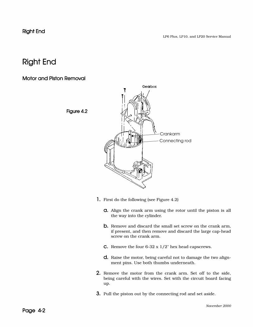
1.1.1.1. First do the following (see Figure 4.2)
a.a.a.a. Align the crank arm using the rotor until the piston is allthe way into the cylinder.
b.b.b.b. Remove and discard the small set screw on the crank arm,if present, and then remove and discard the large cap-headscrew on the crank arm.
c.c.c.c. Remove the four 6-32 x 1/2" hex head capscrews.
d.d.d.d. Raise the motor, being careful not to damage the two align-ment pins. Use both thumbs underneath.
2.2.2.2. Remove the motor from the crank arm. Set off to the side,being careful with the wires. Set with the circuit board facingup.
3.3.3.3. Pull the piston out by the connecting rod and set aside.
Crankarm
Connecting rod
Figure 4.2Figure 4.2Figure 4.2Figure 4.2

Right EndRight EndRight EndRight EndLP6 Plus, LP10, and LP20 Service Manual
November 2000
Page 4-3Page 4-3Page 4-3Page 4-3
Kapseal, Quadring, and Piston Guide Replacement Kapseal, Quadring, and Piston Guide Replacement Kapseal, Quadring, and Piston Guide Replacement Kapseal, Quadring, and Piston Guide Replacement
See Figure 4.3.
1.1.1.1. Use a single-edge razor blade to carefully scrape out the resi-due build-up from inside the cylinder. Wipe the cylinder clean.The inside of the cylinder should be clean and free ofscratches. Wipe out with a paper towel and alcohol if neces-sary.
2.2.2.2. Remove and discard old Kapseal and Quadring from the pistonusing your nail or a delrin screwdriver
3.3.3.3. Remove and discard the eight 8-32 x 3/8" hex set screws fromthe piston angle brackets. Remove Loctite residue from pistonangle brackets using an x-acto knofe.
Piston plate
Quadring
Kapseal
Figure 4.3Figure 4.3Figure 4.3Figure 4.3
Right EndRight EndRight EndRight EndLP6 Plus, LP10, and LP20 Service Manual
November 2000
Page 4-4Page 4-4Page 4-4Page 4-4
4.4.4.4. See Figure 4.4. Remove the old piston guides from the pistonangle brackets. Separate the plastic from the steel guides. Dis-card the plastic guides and clean the steel guides, removingany silicone residue.
5.5.5.5. Install two new 8-32 x 3/8" hex set screws into each of the pis-ton angle brackets. The ends of the screws should be flushwith the inside of the bracket.
Figure 4.4Figure 4.4Figure 4.4Figure 4.4
6.6.6.6. Insert a steel guide into each piston angle bracket, flat sidefirst. Apply two beads of silicone RTV adhesive into plastic pis-ton guides. (Figure 4.5)
7.7.7.7. Insert plastic guides into angle brackets, silicone side inward.Check that no silicone is exposed, wipe clean if necessary. Arubber band may be looped around all 4 piston guide anglebrackets to hold the guides in place.
8.8.8.8. Inspect the Quadring and install into piston groove, verify it isnot twisted.
Plastic piston guide (4)
Steel piston guide (4)
Piston angle bracket (4)Siliconeadhesivehere
Plastic piston guide
Steel piston guide (flat side toward angle bracket)
CautionCautionCautionCaution Use only small amounts of silicone so silicone does not seep outinto the assembly later.
Figure 4.5Figure 4.5Figure 4.5Figure 4.5
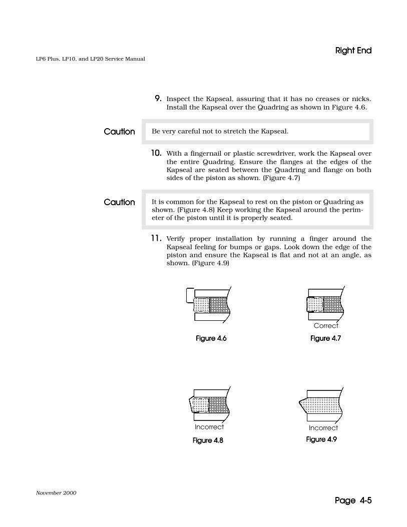
Right EndRight EndRight EndRight EndLP6 Plus, LP10, and LP20 Service Manual
November 2000
Page 4-5Page 4-5Page 4-5Page 4-5
9.9.9.9. Inspect the Kapseal, assuring that it has no creases or nicks.Install the Kapseal over the Quadring as shown in Figure 4.6.
10.10.10.10. With a fingernail or plastic screwdriver, work the Kapseal overthe entire Quadring. Ensure the flanges at the edges of theKapseal are seated between the Quadring and flange on bothsides of the piston as shown. (Figure 4.7)
11.11.11.11. Verify proper installation by running a finger around theKapseal feeling for bumps or gaps. Look down the edge of thepiston and ensure the Kapseal is flat and not at an angle, asshown. (Figure 4.9)
CautionCautionCautionCaution Be very careful not to stretch the Kapseal.
CautionCautionCautionCaution It is common for the Kapseal to rest on the piston or Quadring asshown. (Figure 4.8) Keep working the Kapseal around the perim-eter of the piston until it is properly seated.
Figure 4.6Figure 4.6Figure 4.6Figure 4.6 Figure 4.7Figure 4.7Figure 4.7Figure 4.7
Figure 4.8Figure 4.8Figure 4.8Figure 4.8 Figure 4.9Figure 4.9Figure 4.9Figure 4.9
Correct
Incorrect Incorrect
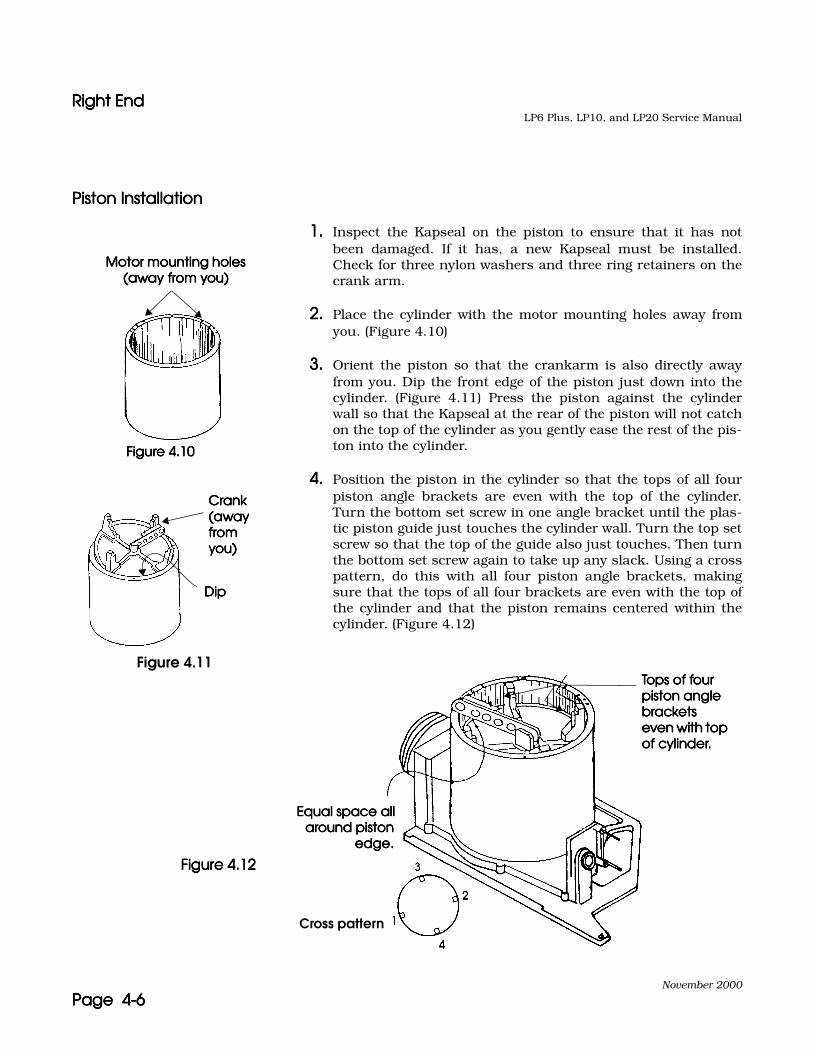
Right EndRight EndRight EndRight EndLP6 Plus, LP10, and LP20 Service Manual
November 2000
Page 4-6Page 4-6Page 4-6Page 4-6
Piston InstallationPiston InstallationPiston InstallationPiston Installation
1.1.1.1. Inspect the Kapseal on the piston to ensure that it has notbeen damaged. If it has, a new Kapseal must be installed.Check for three nylon washers and three ring retainers on thecrank arm.
2.2.2.2. Place the cylinder with the motor mounting holes away fromyou. (Figure 4.10)
3.3.3.3. Orient the piston so that the crankarm is also directly awayfrom you. Dip the front edge of the piston just down into thecylinder. (Figure 4.11) Press the piston against the cylinderwall so that the Kapseal at the rear of the piston will not catchon the top of the cylinder as you gently ease the rest of the pis-ton into the cylinder.
4.4.4.4. Position the piston in the cylinder so that the tops of all fourpiston angle brackets are even with the top of the cylinder.Turn the bottom set screw in one angle bracket until the plas-tic piston guide just touches the cylinder wall. Turn the top setscrew so that the top of the guide also just touches. Then turnthe bottom set screw again to take up any slack. Using a crosspattern, do this with all four piston angle brackets, makingsure that the tops of all four brackets are even with the top ofthe cylinder and that the piston remains centered within thecylinder. (Figure 4.12)
Motor mounting holes Motor mounting holes Motor mounting holes Motor mounting holes (away from you)(away from you)(away from you)(away from you)
Crank Crank Crank Crank (away (away (away (away from from from from you)you)you)you)
Dip Dip Dip Dip
Figure 4.10Figure 4.10Figure 4.10Figure 4.10
Figure 4.11
Equal space allEqual space allEqual space allEqual space allaround pistonaround pistonaround pistonaround piston
edge.edge.edge.edge.
Cross pattern
Tops of four Tops of four Tops of four Tops of four piston angle piston angle piston angle piston angle brackets brackets brackets brackets even with top even with top even with top even with top of cylinder.of cylinder.of cylinder.of cylinder.
Figure 4.12Figure 4.12Figure 4.12Figure 4.12

Right EndRight EndRight EndRight EndLP6 Plus, LP10, and LP20 Service Manual
November 2000
Page 4-7Page 4-7Page 4-7Page 4-7
Set Piston TensionSet Piston TensionSet Piston TensionSet Piston Tension
1.1.1.1. Work the piston back and forth in the cylinder a few times.Push the piston down into the cylinder about 3/4 of the way.
2.2.2.2. Place the right end plate assembly into the Right End Tester,Model L-6951. Add the adapter plug to the manifold air tube.Clamp in place with the two clamps. Switch the tester on.
3.3.3.3. Press and hold the SET PISTON button. Look at the gauge onthe left and see if the needle falls in the good range of 12–18 cmH2O. Hold the button until the tops of the piston anglebrackets are again even with the top of the cylinder.
Note: If a new cylinder is installed in a unit during a PM, the "Good" rangeis 20–25 cmH2O.
4.4.4.4. If the tops of the piston angle brackets are equally distant fromthe top of the cylinder (within 1/16"), and the gauge needle wasin the proper range while the piston was rising, then the brack-ets are adjusted correctly. Go to step 7.
5.5.5.5. If not correct. Adjust the set screws as follows:
Note: If the top set screw is a little tighter than the bottom screw thatangle bracket will be forced a little higher. The reverse is true tocause an angle bracket to ride a little lower.
a.a.a.a. For brackets that are too high, loosen the top set screwslightly. Verify bottom set screw is still snug but not overlytight.
b.b.b.b. For brackets that are too low, tighten the top set screwslightly. Verify bottom set screw is still snug but not overlytight.
c.c.c.c. After adjustments are made, return to the beginning of thistest to re-test the piston tension.
d.d.d.d. If the tension of the piston against the cylinder wall (asmeasured by the gauge) was outside the proper range,adjust all set screws an equal amount in all of the brackets.If above proper range adjust screws counter-clockwise tolower pressure. If below proper range adjust screws clock-wise to raise pressure.
Right EndRight EndRight EndRight EndLP6 Plus, LP10, and LP20 Service Manual
November 2000
Page 4-8Page 4-8Page 4-8Page 4-8
e.e.e.e. After adjustments are made, return to the beginning of thistest to re-test the piston tension.
6.6.6.6. Repeat steps as necessary to obtain proper leveling and ten-sion.
7.7.7.7. Check that the piston is centered in the cylinder.
System Leak TestSystem Leak TestSystem Leak TestSystem Leak Test
1.1.1.1. Press and hold the LEAK TEST button. The needle of the gaugeon the right side must stay in the GOOD range when the leaktest button is depressed. Pressure may drop very slowly whenLEAK TEST button is released.
2.2.2.2. Press and hold the VENT button to release the pressure frominside the manifold.
3.3.3.3. Remove the assembly from the Right End Tester.
4.4.4.4. Remove the air tube adapter plug.
5.5.5.5. Apply a drop of Loctite 242 on each set screw and tilt the sub-assembly such that the Loctite flows around the threads, wipeoff excess. Push the piston about 1/2 way down into the cylin-der.
6.6.6.6. Inspect the Manifold Assembly and verify that:
a.a.a.a. The solenoid is securely mounted.
b.b.b.b. All three pieces of 1/4" internal tubing are present, seatedproperly, and no kinks are present.
c.c.c.c. Patient Pressure and Exhalation Valve tubes appearstraight, secure, and clean.
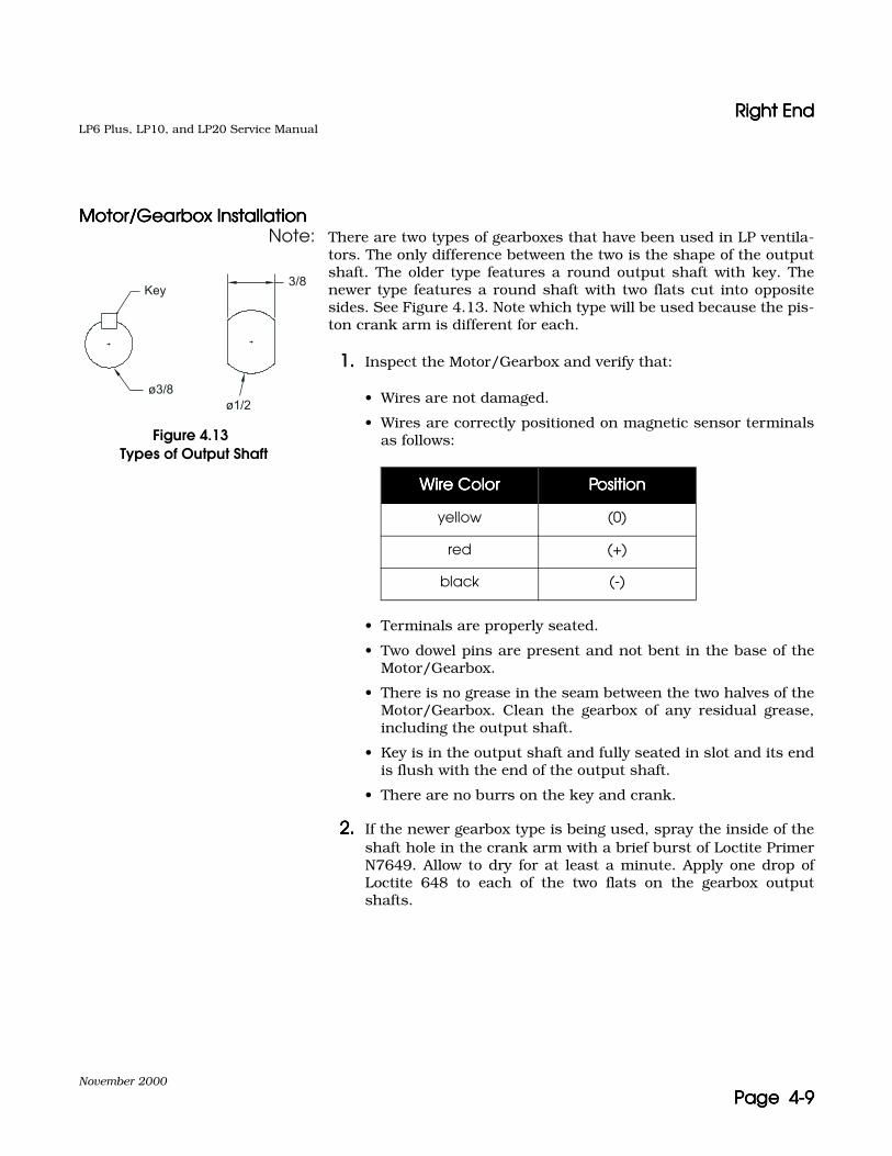
Right EndRight EndRight EndRight EndLP6 Plus, LP10, and LP20 Service Manual
November 2000
Page 4-9Page 4-9Page 4-9Page 4-9
Motor/Gearbox InstallationMotor/Gearbox InstallationMotor/Gearbox InstallationMotor/Gearbox InstallationNote: There are two types of gearboxes that have been used in LP ventila-
tors. The only difference between the two is the shape of the outputshaft. The older type features a round output shaft with key. Thenewer type features a round shaft with two flats cut into oppositesides. See Figure 4.13. Note which type will be used because the pis-ton crank arm is different for each.
1.1.1.1. Inspect the Motor/Gearbox and verify that:
• Wires are not damaged.
• Wires are correctly positioned on magnetic sensor terminalsas follows:
• Terminals are properly seated.
• Two dowel pins are present and not bent in the base of theMotor/Gearbox.
• There is no grease in the seam between the two halves of theMotor/Gearbox. Clean the gearbox of any residual grease,including the output shaft.
• Key is in the output shaft and fully seated in slot and its endis flush with the end of the output shaft.
• There are no burrs on the key and crank.
2.2.2.2. If the newer gearbox type is being used, spray the inside of theshaft hole in the crank arm with a brief burst of Loctite PrimerN7649. Allow to dry for at least a minute. Apply one drop ofLoctite 648 to each of the two flats on the gearbox outputshafts.
Wire ColorWire ColorWire ColorWire Color PositionPositionPositionPosition
yellow (0)
red (+)
black (-)
Figure 4.13Types of Output Shaft
ø3/8
Key
ø1/2
3/8
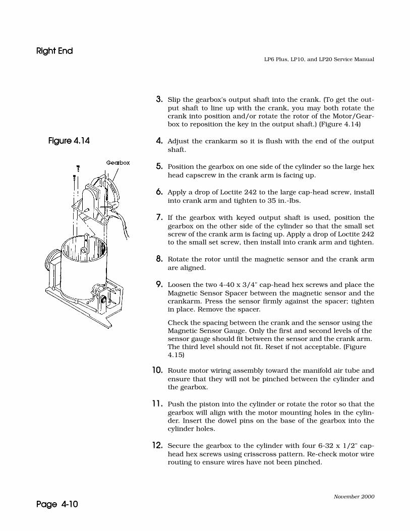
Right EndRight EndRight EndRight EndLP6 Plus, LP10, and LP20 Service Manual
November 2000
Page 4-10Page 4-10Page 4-10Page 4-10
3.3.3.3. Slip the gearbox's output shaft into the crank. (To get the out-put shaft to line up with the crank, you may both rotate thecrank into position and/or rotate the rotor of the Motor/Gear-box to reposition the key in the output shaft.) (Figure 4.14)
4.4.4.4. Adjust the crankarm so it is flush with the end of the outputshaft.
5.5.5.5. Position the gearbox on one side of the cylinder so the large hexhead capscrew in the crank arm is facing up.
6.6.6.6. Apply a drop of Loctite 242 to the large cap-head screw, installinto crank arm and tighten to 35 in.-lbs.
7.7.7.7. If the gearbox with keyed output shaft is used, position thegearbox on the other side of the cylinder so that the small setscrew of the crank arm is facing up. Apply a drop of Loctite 242to the small set screw, then install into crank arm and tighten.
8.8.8.8. Rotate the rotor until the magnetic sensor and the crank armare aligned.
9.9.9.9. Loosen the two 4-40 x 3/4" cap-head hex screws and place theMagnetic Sensor Spacer between the magnetic sensor and thecrankarm. Press the sensor firmly against the spacer; tightenin place. Remove the spacer.
Check the spacing between the crank and the sensor using the Magnetic Sensor Gauge. Only the first and second levels of the sensor gauge should fit between the sensor and the crank arm. The third level should not fit. Reset if not acceptable. (Figure 4.15)
10.10.10.10. Route motor wiring assembly toward the manifold air tube andensure that they will not be pinched between the cylinder andthe gearbox.
11.11.11.11. Push the piston into the cylinder or rotate the rotor so that thegearbox will align with the motor mounting holes in the cylin-der. Insert the dowel pins on the base of the gearbox into thecylinder holes.
12.12.12.12. Secure the gearbox to the cylinder with four 6-32 x 1/2" cap-head hex screws using crisscross pattern. Re-check motor wirerouting to ensure wires have not been pinched.
Figure 4.14Figure 4.14Figure 4.14Figure 4.14

Right EndRight EndRight EndRight EndLP6 Plus, LP10, and LP20 Service Manual
November 2000
Page 4-11Page 4-11Page 4-11Page 4-11
RedRedRedRed
BlackBlackBlackBlack
YellowYellowYellowYellow
Magnetic Magnetic Magnetic Magnetic proximity sensorproximity sensorproximity sensorproximity sensor
Figure 4.15Figure 4.15Figure 4.15Figure 4.15
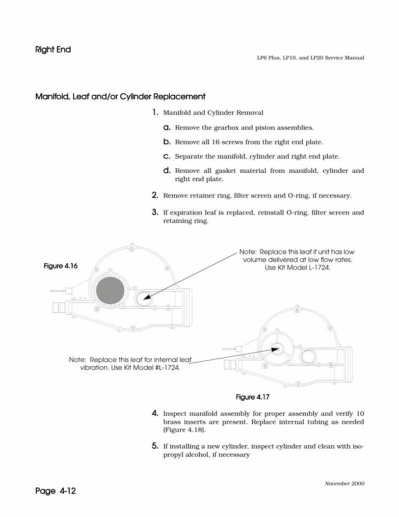
Right EndRight EndRight EndRight EndLP6 Plus, LP10, and LP20 Service Manual
November 2000
Page 4-12Page 4-12Page 4-12Page 4-12
Manifold, Leaf and/or Cylinder ReplacementManifold, Leaf and/or Cylinder ReplacementManifold, Leaf and/or Cylinder ReplacementManifold, Leaf and/or Cylinder Replacement
1.1.1.1. Manifold and Cylinder Removal
a.a.a.a. Remove the gearbox and piston assemblies.
b.b.b.b. Remove all 16 screws from the right end plate.
c.c.c.c. Separate the manifold, cylinder and right end plate.
d.d.d.d. Remove all gasket material from manifold, cylinder andright end plate.
2.2.2.2. Remove retainer ring, filter screen and O-ring, if necessary.
3.3.3.3. If expiration leaf is replaced, reinstall O-ring, filter screen andretaining ring.
4.4.4.4. Inspect manifold assembly for proper assembly and verify 10brass inserts are present. Replace internal tubing as needed(Figure 4.18).
5.5.5.5. If installing a new cylinder, inspect cylinder and clean with iso-propyl alcohol, if necessary
Note: Replace this leaf if unit has low volume delivered at low flow rates.
Use Kit Model L-1724.
Note: Replace this leaf for internal leaf vibration. Use Kit Model #L-1724.
Figure 4.16Figure 4.16Figure 4.16Figure 4.16
Figure 4.17Figure 4.17Figure 4.17Figure 4.17
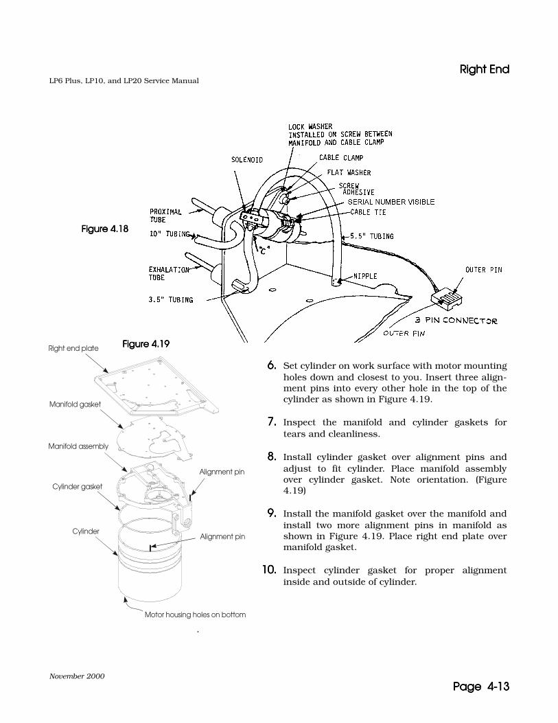
Right EndRight EndRight EndRight EndLP6 Plus, LP10, and LP20 Service Manual
November 2000
Page 4-13Page 4-13Page 4-13Page 4-13
.
Right end plate
Manifold gasket
Manifold assembly
Cylinder gasket
Cylinder
Alignment pin
Motor housing holes on bottom
Alignment pin
6.6.6.6. Set cylinder on work surface with motor mountingholes down and closest to you. Insert three align-ment pins into every other hole in the top of thecylinder as shown in Figure 4.19.
7.7.7.7. Inspect the manifold and cylinder gaskets fortears and cleanliness.
8.8.8.8. Install cylinder gasket over alignment pins andadjust to fit cylinder. Place manifold assemblyover cylinder gasket. Note orientation. (Figure4.19)
9.9.9.9. Install the manifold gasket over the manifold andinstall two more alignment pins in manifold asshown in Figure 4.19. Place right end plate overmanifold gasket.
10.10.10.10. Inspect cylinder gasket for proper alignmentinside and outside of cylinder.
Figure 4.18Figure 4.18Figure 4.18Figure 4.18
Figure 4.19Figure 4.19Figure 4.19Figure 4.19
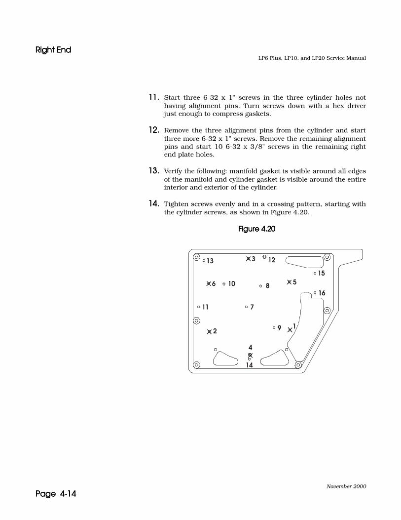
Right EndRight EndRight EndRight EndLP6 Plus, LP10, and LP20 Service Manual
November 2000
Page 4-14Page 4-14Page 4-14Page 4-14
11.11.11.11. Start three 6-32 x 1" screws in the three cylinder holes nothaving alignment pins. Turn screws down with a hex driverjust enough to compress gaskets.
12.12.12.12. Remove the three alignment pins from the cylinder and startthree more 6-32 x 1" screws. Remove the remaining alignmentpins and start 10 6-32 x 3/8" screws in the remaining rightend plate holes.
13.13.13.13. Verify the following: manifold gasket is visible around all edgesof the manifold and cylinder gasket is visible around the entireinterior and exterior of the cylinder.
14.14.14.14. Tighten screws evenly and in a crossing pattern, starting withthe cylinder screws, as shown in Figure 4.20.
Figure 4.20Figure 4.20Figure 4.20Figure 4.20
13 3
6 10
12
155
168
711
2
4
14
9 1
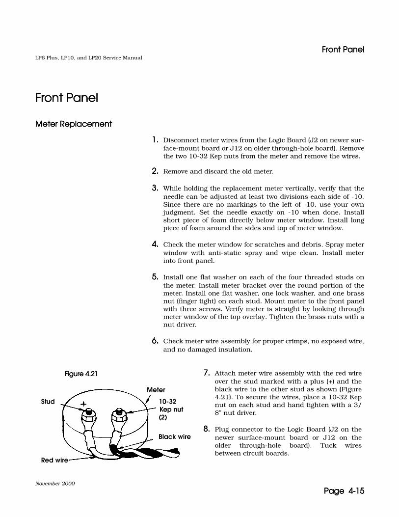
Front PanelFront PanelFront PanelFront PanelLP6 Plus, LP10, and LP20 Service Manual
November 2000
Page 4-15Page 4-15Page 4-15Page 4-15
Front PanelFront PanelFront PanelFront Panel
Meter ReplacementMeter ReplacementMeter ReplacementMeter Replacement
1.1.1.1. Disconnect meter wires from the Logic Board (J2 on newer sur-face-mount board or J12 on older through-hole board). Removethe two 10-32 Kep nuts from the meter and remove the wires.
2.2.2.2. Remove and discard the old meter.
3.3.3.3. While holding the replacement meter vertically, verify that theneedle can be adjusted at least two divisions each side of -10.Since there are no markings to the left of -10, use your ownjudgment. Set the needle exactly on -10 when done. Installshort piece of foam directly below meter window. Install longpiece of foam around the sides and top of meter window.
4.4.4.4. Check the meter window for scratches and debris. Spray meterwindow with anti-static spray and wipe clean. Install meterinto front panel.
5.5.5.5. Install one flat washer on each of the four threaded studs onthe meter. Install meter bracket over the round portion of themeter. Install one flat washer, one lock washer, and one brassnut (finger tight) on each stud. Mount meter to the front panelwith three screws. Verify meter is straight by looking throughmeter window of the top overlay. Tighten the brass nuts with anut driver.
6.6.6.6. Check meter wire assembly for proper crimps, no exposed wire,and no damaged insulation.
Stud
Meter
Red wire
Black wire
10-32 Kep nut (2)
7.7.7.7. Attach meter wire assembly with the red wireover the stud marked with a plus (+) and theblack wire to the other stud as shown (Figure4.21). To secure the wires, place a 10-32 Kepnut on each stud and hand tighten with a 3/8" nut driver.
8.8.8.8. Plug connector to the Logic Board (J2 on thenewer surface-mount board or J12 on theolder through-hole board). Tuck wiresbetween circuit boards.
Figure 4.21Figure 4.21Figure 4.21Figure 4.21

Front PanelFront PanelFront PanelFront PanelLP6 Plus, LP10, and LP20 Service Manual
November 2000
Page 4-16Page 4-16Page 4-16Page 4-16
Figure 4.22Figure 4.22Figure 4.22Figure 4.22
Power/Motor Board RemovalPower/Motor Board RemovalPower/Motor Board RemovalPower/Motor Board Removal
1.1.1.1. Check for the presence of the resistor plug on the Power/Motorboard. Install resistor plug for a minimum of one minute (at J6on the newer surface-mount board or J3 on the older through-hole board).
2.2.2.2. Remove the five 6-32 x 3/16" button-head hex screws and one4-40 x 3/16" button-head hex screw, if present, securing thePower/Motor board to the stand-offs. (Figure 4.22)
3.3.3.3. Remove the 6-32 x 3/4" button-head hex screw from the heatsink dampener, if present.
4.4.4.4. Raise the Power/Motor board carefully from the front panel.There are two sets of pin connectors.
Power/motor boardPower/motor boardPower/motor boardPower/motor board
Front panelFront panelFront panelFront panel
Logic boardLogic boardLogic boardLogic board
CautionCautionCautionCaution Use of an anti-static workstation is necessary to handle the frontpanel and circuit boards safely.

Front PanelFront PanelFront PanelFront PanelLP6 Plus, LP10, and LP20 Service Manual
November 2000
Page 4-17Page 4-17Page 4-17Page 4-17
Logic Board RemovalLogic Board RemovalLogic Board RemovalLogic Board Removal
Note: Do not remove the pressure limit knob (LP10 and LP20 only).
Note: Previously, when through-hole logic boards were replaced, the time& date EEPROM U24 had to be transferred from the old board to thenew board to retain device history (i.e., hours since last preventivemaintenance). Now, with the surface-mount board, the time & dateEEPROM (now U26) has a different design. The EEPROM from U24on the through-hole board will not fit in U26 on the surface-mountboard. Therefore, when a through-hole logic board is replaced with asurface-mount board, a preventive maintenance must be performed.Otherwise, there would be no record of device hours since the lastpreventive maintenance.
Note: When a surface-mount logic board is replaced with another surface-mount logic board, the U26 time & date EEPROM is to be trans-ferred to the new board. A preventive maintenance is not automati-cally required.
1.1.1.1. Turn all seven knobs completely counter-clockwise. Loosen theset screws securing the knobs to the shafts. Remove the knobsand the O-rings (behind BREATHING EFFORT and VOLUME).
2.2.2.2. Remove the five 6-32 x 11/16" stand-offs, the one 6-32 x 3/16"button-head hex screw, and the one 4-40 x 3/16" button-headhex screw (or 4-40 x 11/16" stand-off) securing the Logic boardto the front panel.
3.3.3.3. Disconnect the meter wire assembly from the Logic board (J2on the newer surface-mount board or J12 on the olderthrough-hole board).
4.4.4.4. Disconnect the Display board ribbon cable from the Logicboard (J4 on the newer surface-mount board or J9 on the olderthrough-hole board).
5.5.5.5. Raise the Logic board from the front panel.
Front PanelFront PanelFront PanelFront PanelLP6 Plus, LP10, and LP20 Service Manual
November 2000
Page 4-18Page 4-18Page 4-18Page 4-18
Display Board RemovalDisplay Board RemovalDisplay Board RemovalDisplay Board Removal
1.1.1.1. Remove the 6-32 x 3/16" button-head hex screws from the topof the Display board (three screws if removing a newer surface-mount board or two screws if removing an older through-holeboard).
2.2.2.2. Remove the three flat head screws from the bottom of the Dis-play board. Remove the Display board.
Display Board InstallationDisplay Board InstallationDisplay Board InstallationDisplay Board Installation
1.1.1.1. Check the Display board for damaged components and traces.
2.2.2.2. Check the ribbon cable on the replacement Display boardensuring that the:
• Connectors are fully pressed together.
• Wires are not broken.
• Colored line on the cable is connected to the #1 pin in thegray connector. (This is the pin indicated by a polarizingmark on the connector.)
3.3.3.3. Mount the Display board by installing the 6-32 x 3/16" button-head hex screws on the top of the Display board. Use threescrews if a newer surface-mount Power/Motor board will bereinstalled, or two screws (leave middle open) if the olderthrough-hole Power/Motor board will be reinstalled.
4.4.4.4. Install the three flat head screws on the bottom of the Displayboard using Loctite 242.
Note: The Logic board and the Power/Motor board are sensitive to staticelectricity. Take precautions to eliminate static before handling thecircuit boards.
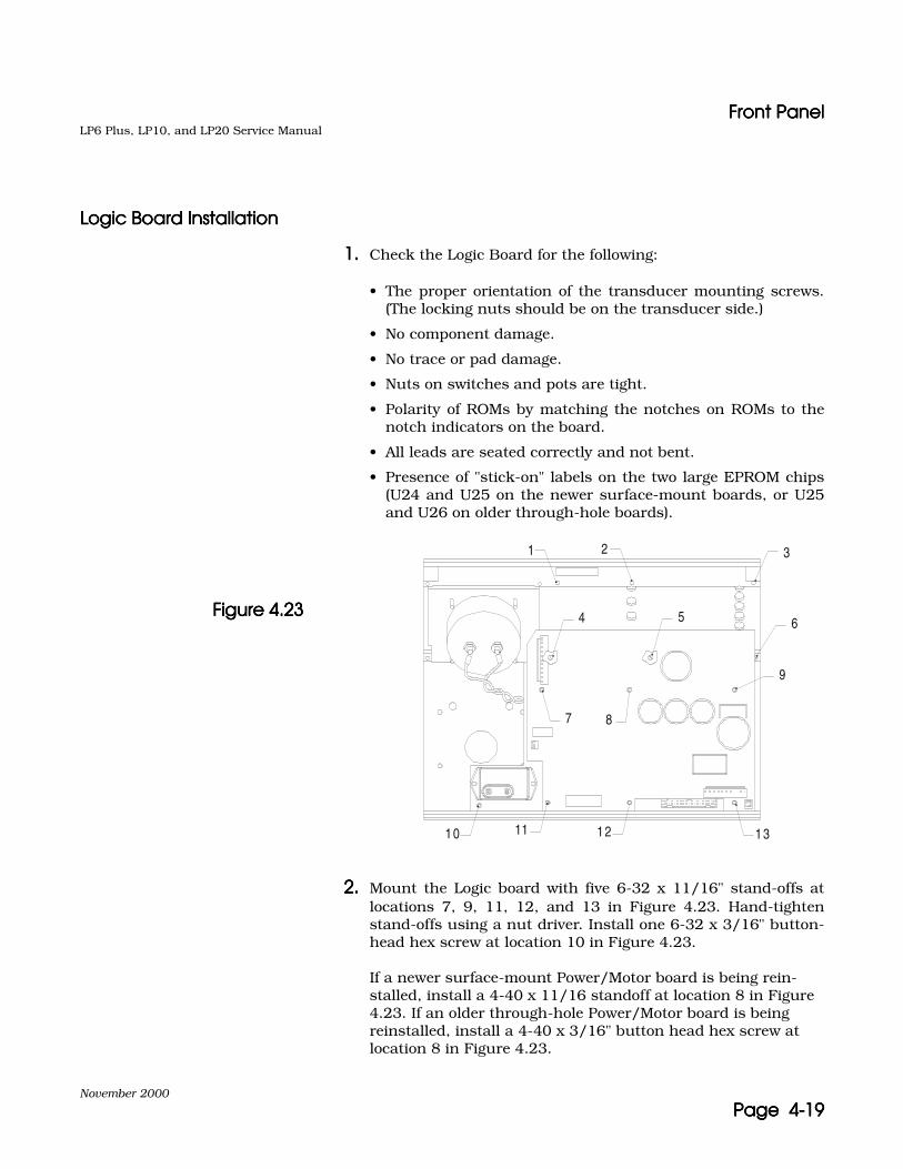
Front PanelFront PanelFront PanelFront PanelLP6 Plus, LP10, and LP20 Service Manual
November 2000
Page 4-19Page 4-19Page 4-19Page 4-19
Logic Board InstallationLogic Board InstallationLogic Board InstallationLogic Board Installation
1.1.1.1. Check the Logic Board for the following:
• The proper orientation of the transducer mounting screws.(The locking nuts should be on the transducer side.)
• No component damage.
• No trace or pad damage.
• Nuts on switches and pots are tight.
• Polarity of ROMs by matching the notches on ROMs to thenotch indicators on the board.
• All leads are seated correctly and not bent.
• Presence of "stick-on" labels on the two large EPROM chips(U24 and U25 on the newer surface-mount boards, or U25and U26 on older through-hole boards).
2.2.2.2. Mount the Logic board with five 6-32 x 11/16" stand-offs atlocations 7, 9, 11, 12, and 13 in Figure 4.23. Hand-tightenstand-offs using a nut driver. Install one 6-32 x 3/16" button-head hex screw at location 10 in Figure 4.23.
If a newer surface-mount Power/Motor board is being rein-stalled, install a 4-40 x 11/16 standoff at location 8 in Figure 4.23. If an older through-hole Power/Motor board is being reinstalled, install a 4-40 x 3/16" button head hex screw at location 8 in Figure 4.23.
13
1 2 3
4 6
7 8
9
10 11 12
5Figure 4.23Figure 4.23Figure 4.23Figure 4.23

Front PanelFront PanelFront PanelFront PanelLP6 Plus, LP10, and LP20 Service Manual
November 2000
Page 4-20Page 4-20Page 4-20Page 4-20
3.3.3.3. Connect the Display board ribbon cable to the Logic board (J4on the newer surface-mount board or J9 on the older through-hole board).
4.4.4.4. Connect the meter wiring assembly to the Logic board (J2 onthe newer surface-mount board or J12 on the older through-hole board).
5.5.5.5. If a new Logic board has been installed, transfer the time anddate EEPROM from the old board, if possible, to retain devicehistory.
a.a.a.a. Through-hole board replacing a through-hole board:
Transfer EEPROM U24 using an I.C extraction tool. Notepolarity.
b.b.b.b. Surface-mount board replacing a surface-mount board:
Transfer EEPROM U26 using an I.C extraction tool. Notepolarity.
c.c.c.c. Surface-mount board replacing a through-hole board:
EEPROMs have incompatible sockets and cannot be trans-ferred. Keep the existing U26 in the new board. A PM mustbe performed on this unit.
d.d.d.d. Through-hole board replacing a surface-mount board:
EEPROMs have incompatible sockets and cannot be trans-ferred. Keep the existing U24 in the new board. A PM mustbe performed on this unit.

Front PanelFront PanelFront PanelFront PanelLP6 Plus, LP10, and LP20 Service Manual
November 2000
Page 4-21Page 4-21Page 4-21Page 4-21
Power/Motor Board Installation Power/Motor Board Installation Power/Motor Board Installation Power/Motor Board Installation
Figure 4.24Figure 4.24Figure 4.24Figure 4.24
1.1.1.1. Check the Power/Motor Board to ensure that:
• No component damage exists.
• The resistor plug is inserted into the 10-pin connector (J6 onthe newer surface-mount board, or J3 on the older through-hole board).
• Polarity of EPROM (U17 on the newer surface-mount board,or U10 on the older through-hole board) is correct by match-ing the notches on the ROM to the notch indicator on theboard.
• EPROM leads are seated correctly and not bent.
• EPROM has a label.
2.2.2.2. Carefully mount the Power/Motor Board by positioning it overthe pins in the Logic Board. Press the Power/Motor Boardevenly down onto the pins. (Figure 4.24)
3.3.3.3. Check all the pins connecting the boards to make sure that nopins are bent and all pins are fully seated into the connectors.
4.4.4.4. Secure the Power/Motor Board using five 6-32 x 3/16" button-head hex screws at locations 7, 9, 11, 12, and 13 in Figure4.23. If a newer surface-mount Power/Motor board is used,secure with a 4-40 x 3/16" button head hex screw at location 8in Figure 4.23.
Power/motor boardPower/motor boardPower/motor boardPower/motor board
Front panelFront panelFront panelFront panel
Logic boardLogic boardLogic boardLogic board

Front PanelFront PanelFront PanelFront PanelLP6 Plus, LP10, and LP20 Service Manual
November 2000
Page 4-22Page 4-22Page 4-22Page 4-22
5.5.5.5. If an older through-hole Power/Motor board is used, install a6-32 x 3/4" button-head hex screw to secure the heat sinkdampener to the front panel.
6.6.6.6. If a through-hole Power/Motor board has replaced a surface-mount board, a fan assembly from the L-1618 Fan Kit mustalso be installed.
Knob InstallationKnob InstallationKnob InstallationKnob Installation
1.1.1.1. Verify all shafts on the front panel are fully counter-clockwise.
2.2.2.2. Place nylon washers and then O-rings into locking knobs andinstall onto the two shafts with brass nuts (VOLUMEVOLUMEVOLUMEVOLUME andBREATHING EFFORTBREATHING EFFORTBREATHING EFFORTBREATHING EFFORT). Position the knobs with respect to theminimum overlay markings. Obtain correct spacing with a .025feeler gauge between the knob and the front panel. Tighten theset screws in each knob.
3.3.3.3. Take five 5/8" regular knobs. Obtain correct spacing with a.025 feeler gauge and orient indicator lines at the minimum(furthest counter-clockwise) setting marks on the overlay.Tighten knobs.
Note: The indicators on the knobs must center precisely on the minimumsetting marks on the overlay.
4.4.4.4. Check that all knobs are in fact turned fully counter-clock-wise. Check that there is some tension on the locking knobsduring rotation.

Front PanelFront PanelFront PanelFront PanelLP6 Plus, LP10, and LP20 Service Manual
November 2000
Page 4-23Page 4-23Page 4-23Page 4-23
Overlay ReplacementOverlay ReplacementOverlay ReplacementOverlay Replacement
1.1.1.1. Remove the overlay to be replaced. Scrape the adhesive residuecompletely from the front panel. Residue left on the front panelwhere the overlay is adhered will cause a bubble or bump.
2.2.2.2. Check overlays for flaws (scratches, discoloration, bubbles,illegible silk-screening or holes) before installing.
3.3.3.3. Remove adhesive backing from top overlay window, if present.Spray both front and back of meter window area of the topoverlay with anti-static spray and wipe to prevent spotting.
4.4.4.4. Check for continuous adhesive on the back of the overlay.
The following are suggestions for installing the overlays:
a.a.a.a. Peel back a small portion of the overlay backing on oneend. Position the overlay accurately and then press downthe exposed adhesive portion of the overlay. Now peel theremainder of the backing while pressing down the overlayas the backing is removed to avoid air bubbles from beingtrapped.
b.b.b.b. Peel back the entire overlay, carefully holding the edges.Lay overlay on panel lightly and press up the center of theoverlay. Smooth overlay from center to outside edges.
5.5.5.5. Check all overlays to ensure edges are even with panel edges.Smooth the overlays as needed.
Top overlay
Striker plateStriker plateStriker plateStriker plateFigure 4.25Figure 4.25Figure 4.25Figure 4.25
Front PanelFront PanelFront PanelFront PanelLP6 Plus, LP10, and LP20 Service Manual
November 2000
Page 4-24Page 4-24Page 4-24Page 4-24
PLC Replacement (LP10/LP20 only)PLC Replacement (LP10/LP20 only)PLC Replacement (LP10/LP20 only)PLC Replacement (LP10/LP20 only)
PLC Removal PLC Removal PLC Removal PLC Removal 1.1.1.1. Remove the PLC knob and knob spring, using a 1/16" hexdriver.
2.2.2.2. Remove the bezel overlay with "Patient Pressure" and "Exhala-tion Valve" printed on it.
3.3.3.3. Remove the two Phillips head screws from the bezel.
4.4.4.4. Remove the two hex head screws from the bezel, using a 7/64"hex driver.
5.5.5.5. Remove the bezel.
6.6.6.6. Remove the gasket from around the patient pressure port.
7.7.7.7. Remove the four hex head screws from the PLC manifold, usinga 5/64" hex driver.
8.8.8.8. Remove the PLC Manifold.
PLC InstallationPLC InstallationPLC InstallationPLC Installation 1.1.1.1. Fasten the PLC manifold to the ventilator's front panel with thefour hex head screws, and tighten using a crisscross pattern.
2.2.2.2. Rotate the PLC knob shaft clockwise until the two set screwsare pointing to the right of the assembly.
3.3.3.3. Install the patient pressure port gasket.
4.4.4.4. Set the bezel onto the PLC manifold.
5.5.5.5. Install two Phillips head screws in the top of the bezel. Handtighten, using only light pressure. Do not over tighten.
6.6.6.6. Install two hex head screws in the bottom of the bezel. Handtighten, using only light pressure. Do not over tighten.
7.7.7.7. Install a new bezel overlay over the two Phillips head screws.
PLC Knob Installation:PLC Knob Installation:PLC Knob Installation:PLC Knob Installation: 1.1.1.1. Install the coil spring over the adjustment shaft to rest aroundthe shaft busing.

Front PanelFront PanelFront PanelFront PanelLP6 Plus, LP10, and LP20 Service Manual
November 2000
Page 4-25Page 4-25Page 4-25Page 4-25
2.2.2.2. Install knob base, grooved side connecting with the spring.
3.3.3.3. Align notches in knob base to the corners of the shaft busing.
4.4.4.4. Apply adhesive, Loctite 425, to the top knob set screw threads.
5.5.5.5. Compress the spring with the knob base and hold down.
6.6.6.6. Install the top knob on the adjustment shaft, with the setscrew on the flat side of the shaft. Tighten the set screw.
7.7.7.7. Check the function of the locking knob.

Left End PlateLeft End PlateLeft End PlateLeft End PlateLP6 Plus, LP10, and LP20 Service Manual
November 2000
Page 4-26Page 4-26Page 4-26Page 4-26
Left End PlateLeft End PlateLeft End PlateLeft End Plate
Figure 4.26Figure 4.26Figure 4.26Figure 4.26
Fan Assembly ReplacementFan Assembly ReplacementFan Assembly ReplacementFan Assembly Replacement
See Figure 4.26.
1.1.1.1. Remove the two 6-32 x 3/8" cap-head screws.
2.2.2.2. Remove and discard the old fan.
3.3.3.3. Attach the fan, at opposite corners, to left end plate using two#6 flat washers (per corner between fan and plate) and two 6-32 x 3/8" cap-head screws. Hand tighten. Ensure that thelabel is away from the plate and the wires come out of the fantowards the bottom front of the ventilator.
6-32x3/8" Nylok (2)
Fan
#6 Flat washer (4)
Left end plate
Nurse call board
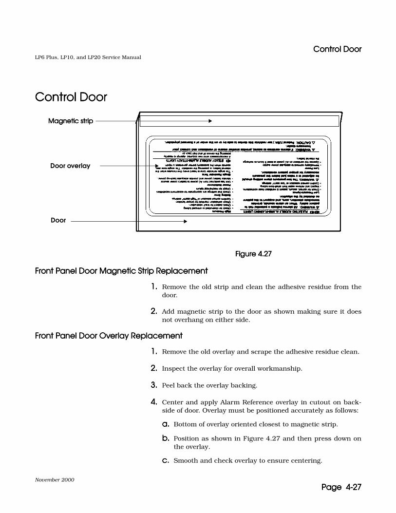
Control DoorControl DoorControl DoorControl DoorLP6 Plus, LP10, and LP20 Service Manual
November 2000
Page 4-27Page 4-27Page 4-27Page 4-27
Control DoorControl DoorControl DoorControl Door
Figure 4.27Figure 4.27Figure 4.27Figure 4.27
Front Panel Door Magnetic Strip ReplacementFront Panel Door Magnetic Strip ReplacementFront Panel Door Magnetic Strip ReplacementFront Panel Door Magnetic Strip Replacement
1.1.1.1. Remove the old strip and clean the adhesive residue from thedoor.
2.2.2.2. Add magnetic strip to the door as shown making sure it doesnot overhang on either side.
Front Panel Door Overlay ReplacementFront Panel Door Overlay ReplacementFront Panel Door Overlay ReplacementFront Panel Door Overlay Replacement
1.1.1.1. Remove the old overlay and scrape the adhesive residue clean.
2.2.2.2. Inspect the overlay for overall workmanship.
3.3.3.3. Peel back the overlay backing.
4.4.4.4. Center and apply Alarm Reference overlay in cutout on back-side of door. Overlay must be positioned accurately as follows:
a.a.a.a. Bottom of overlay oriented closest to magnetic strip.
b.b.b.b. Position as shown in Figure 4.27 and then press down onthe overlay.
c.c.c.c. Smooth and check overlay to ensure centering.
Magnetic stripMagnetic stripMagnetic stripMagnetic strip
Door overlay
Door

Back PanelBack PanelBack PanelBack PanelLP6 Plus, LP10, and LP20 Service Manual
November 2000
Page 4-28Page 4-28Page 4-28Page 4-28
Back PanelBack PanelBack PanelBack Panel
AC Cord ReplacementAC Cord ReplacementAC Cord ReplacementAC Cord Replacement
See Figure 4.28 and 4.29.
1.1.1.1. Note the position of the power cord connections. On olderLP6+/LP10 and all LP20 models, all three power cord wiresattach to the terminal strip. An additional green and yellowwire connects the terminal strip to the chassis ground stud.On newer LP6+/LP10 models, the white and black wires fromthe power cord attach to the terminal strip, while the longergreen wire from the power cord attaches directly to the chassisground stud.
2.2.2.2. Disconnect the power cord from all three points of attachment.
3.3.3.3. Remove the green and yellow wire from between the terminalstrip and chassis ground stud, if present.
4.4.4.4. Squeeze the strain relief with pliers to pull the power cord fromthe rear panel.
Figure 4.28. Figure 4.28. Figure 4.28. Figure 4.28.
Newer LP6+/LP10Newer LP6+/LP10Newer LP6+/LP10Newer LP6+/LP10
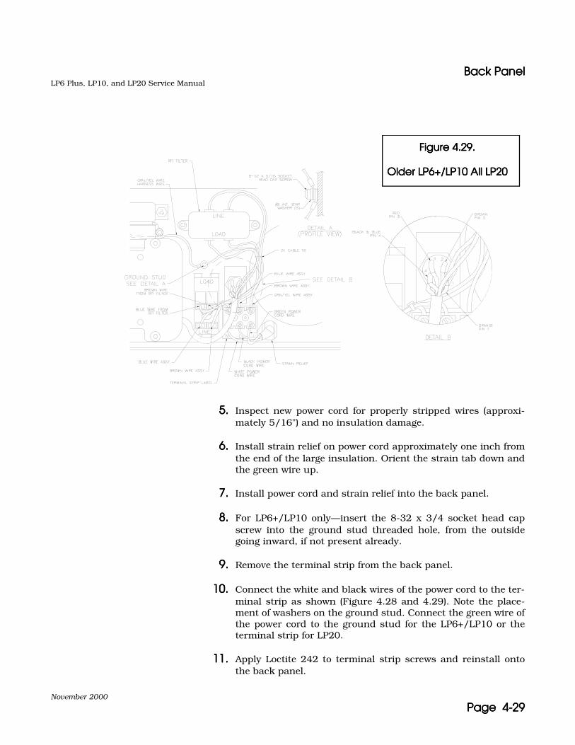
Back PanelBack PanelBack PanelBack PanelLP6 Plus, LP10, and LP20 Service Manual
November 2000
Page 4-29Page 4-29Page 4-29Page 4-29
5.5.5.5. Inspect new power cord for properly stripped wires (approxi-mately 5/16") and no insulation damage.
6.6.6.6. Install strain relief on power cord approximately one inch fromthe end of the large insulation. Orient the strain tab down andthe green wire up.
7.7.7.7. Install power cord and strain relief into the back panel.
8.8.8.8. For LP6+/LP10 only—insert the 8-32 x 3/4 socket head capscrew into the ground stud threaded hole, from the outsidegoing inward, if not present already.
9.9.9.9. Remove the terminal strip from the back panel.
10.10.10.10. Connect the white and black wires of the power cord to the ter-minal strip as shown (Figure 4.28 and 4.29). Note the place-ment of washers on the ground stud. Connect the green wire ofthe power cord to the ground stud for the LP6+/LP10 or theterminal strip for LP20.
11.11.11.11. Apply Loctite 242 to terminal strip screws and reinstall ontothe back panel.
Figure 4.29. Figure 4.29. Figure 4.29. Figure 4.29.
Older LP6+/LP10 All LP20Older LP6+/LP10 All LP20Older LP6+/LP10 All LP20Older LP6+/LP10 All LP20
Back PanelBack PanelBack PanelBack PanelLP6 Plus, LP10, and LP20 Service Manual
November 2000
Page 4-30Page 4-30Page 4-30Page 4-30
12.12.12.12. For LP20 only—connect the additional green and yellow wire tothe terminal block and the ground stud.
13.13.13.13. Connect the green and yellow wire harness wire and any addi-tional washers or nuts to the ground stud as shown in Figure4.29. Secure the ground stud.
Replacement of AC ON/OFF SwitchReplacement of AC ON/OFF SwitchReplacement of AC ON/OFF SwitchReplacement of AC ON/OFF Switch
See Figure 4.28 and 4.29.
1.1.1.1. Disconnect the four wires on the old ON/OFF switch, takingnote of their location.
2.2.2.2. Depress the two locking tabs on each end of the ON/OFFswitch and remove the switch from the back panel.
3.3.3.3. Bend two lugs on the new ON/OFF switch to match the bentlugs on the old ON/OFF switch.
4.4.4.4. Install the new ON/OFF switch in the back panel with the zerotoward the bottom edge of the back panel.
5.5.5.5. Reconnect the four wires to their previous locations on the newON/OFF switch. The wires from the terminal strip go to thelugs closest to the bottom edge of the back panel (Figure 4.28and 4.29).
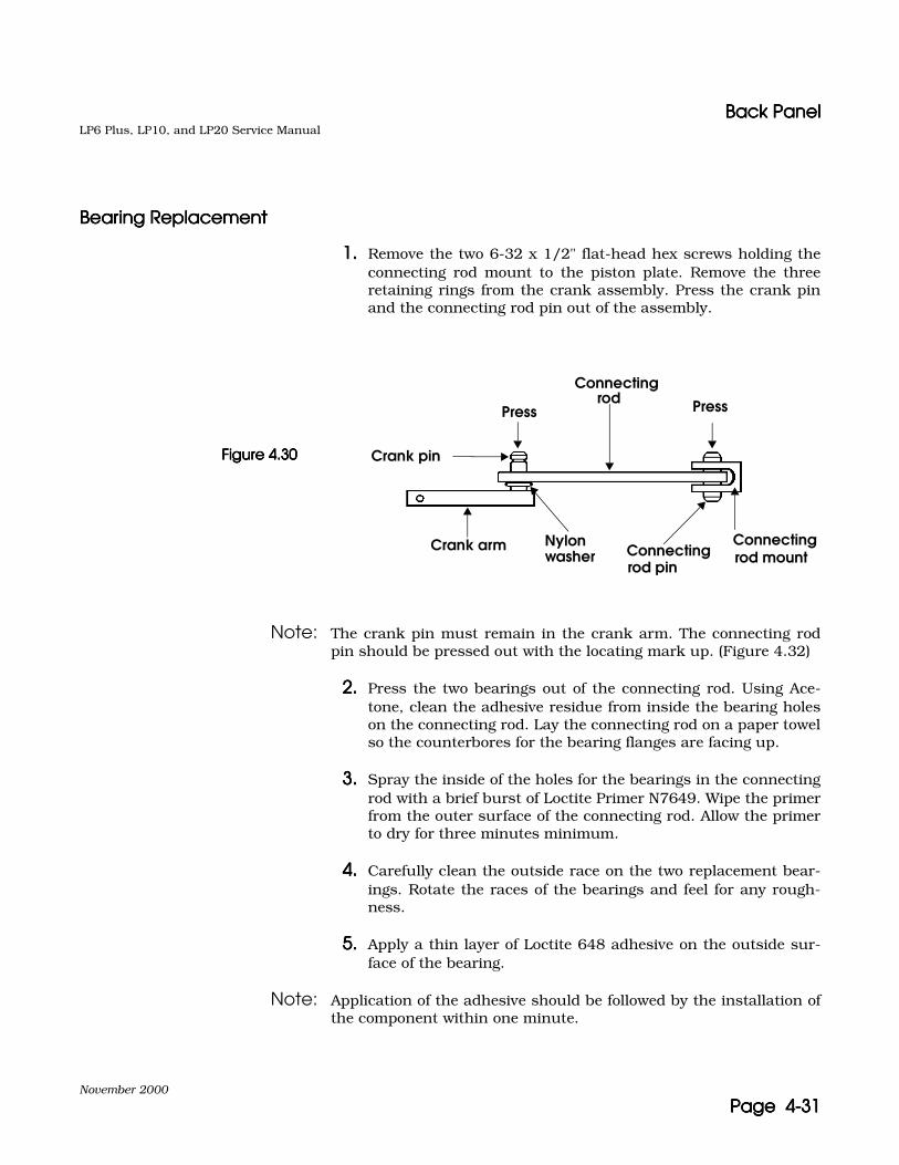
Back PanelBack PanelBack PanelBack PanelLP6 Plus, LP10, and LP20 Service Manual
November 2000
Page 4-31Page 4-31Page 4-31Page 4-31
Bearing ReplacementBearing ReplacementBearing ReplacementBearing Replacement
1.1.1.1. Remove the two 6-32 x 1/2" flat-head hex screws holding theconnecting rod mount to the piston plate. Remove the threeretaining rings from the crank assembly. Press the crank pinand the connecting rod pin out of the assembly.
Note: The crank pin must remain in the crank arm. The connecting rodpin should be pressed out with the locating mark up. (Figure 4.32)
2.2.2.2. Press the two bearings out of the connecting rod. Using Ace-tone, clean the adhesive residue from inside the bearing holeson the connecting rod. Lay the connecting rod on a paper towelso the counterbores for the bearing flanges are facing up.
3.3.3.3. Spray the inside of the holes for the bearings in the connectingrod with a brief burst of Loctite Primer N7649. Wipe the primerfrom the outer surface of the connecting rod. Allow the primerto dry for three minutes minimum.
4.4.4.4. Carefully clean the outside race on the two replacement bear-ings. Rotate the races of the bearings and feel for any rough-ness.
5.5.5.5. Apply a thin layer of Loctite 648 adhesive on the outside sur-face of the bearing.
Note: Application of the adhesive should be followed by the installation ofthe component within one minute.
Press
Connecting rod Press
Crank pin
Crank arm Nylon washer Connecting
rod pin
Connecting rod mount
Figure 4.30Figure 4.30Figure 4.30Figure 4.30

Back PanelBack PanelBack PanelBack PanelLP6 Plus, LP10, and LP20 Service Manual
November 2000
Page 4-32Page 4-32Page 4-32Page 4-32
Figure 4.31Figure 4.31Figure 4.31Figure 4.31
6.6.6.6. Press the bearing into the connecting rod, using a bearingpress, bearing press tool, and bearing press plate (Figure 4.31).
7.7.7.7. Remove any excess adhesive.
Bearing (2)
Recesses for bearingflanges face up
CautionCautionCautionCaution Press only on the outer race of the bearings.

Back PanelBack PanelBack PanelBack PanelLP6 Plus, LP10, and LP20 Service Manual
November 2000
Page 4-33Page 4-33Page 4-33Page 4-33
Figure 4.32Figure 4.32Figure 4.32Figure 4.32
8.8.8.8. Hold the connecting rod mount with the locating mark side up.Start the connecting rod mount pin through the hole frombelow. Place a nylon washer, the connecting rod (bearingflanges up), and another nylon washer onto the pin. (Figure4.32) Slip the pin up through these parts. Install the assemblyin a mounting bracket press plate. Press the pin through themount until the two grooves are equally spaced on either sideof the mount. (Figure 4.33)
Figure 4.33Figure 4.33Figure 4.33Figure 4.33
Note: Turn over assembly and press as shown.
Nylon washer (2)
Locating markConnecting rod
Connecting rod pin
Press
Connecting rod pin
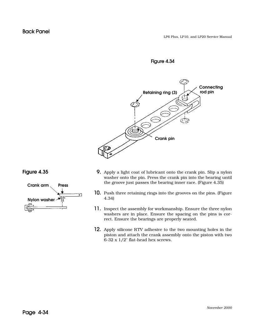
Back PanelBack PanelBack PanelBack PanelLP6 Plus, LP10, and LP20 Service Manual
November 2000
Page 4-34Page 4-34Page 4-34Page 4-34
Figure 4.34Figure 4.34Figure 4.34Figure 4.34
Figure 4.35 9.9.9.9. Apply a light coat of lubricant onto the crank pin. Slip a nylonwasher onto the pin. Press the crank pin into the bearing untilthe groove just passes the bearing inner race. (Figure 4.35)
10.10.10.10. Push three retaining rings into the grooves on the pins. (Figure4.34)
11.11.11.11. Inspect the assembly for workmanship. Ensure the three nylonwashers are in place. Ensure the spacing on the pins is cor-rect. Ensure the bearings are properly seated.
12.12.12.12. Apply silicone RTV adhesive to the two mounting holes in thepiston and attach the crank assembly onto the piston with two6-32 x 1/2" flat-head hex screws.
Connecting rod pinRetaining ring (3)
Crank pin
Crank arm Press
Nylon washer
November 2000
Page 5-1Page 5-1Page 5-1Page 5-1
5555 FormsFormsFormsFormsOn the following pages are blank copies of the forms used when servic-ing the LP6 Plus, LP10, and LP20 Volume Ventilators. These forms arethe:
• Ventilator Run-In Log• Ventilator Service Record
Photocopy these forms and use them to document maintenance andrepair of your ventilator. Use these forms for your internal documenta-tion and to ensure accurate records are kept about necessary mainte-nance and repairs.
You must complete a Service Record and Run-In Log and return a copyto Nellcor Puritan Bennett each time you repair an LP6 Plus, LP10, orLP20 Volume Ventilator.

LP6 Plus, LP10, and LP20 Service Manual
November 2000
Page 5-2Page 5-2Page 5-2Page 5-2
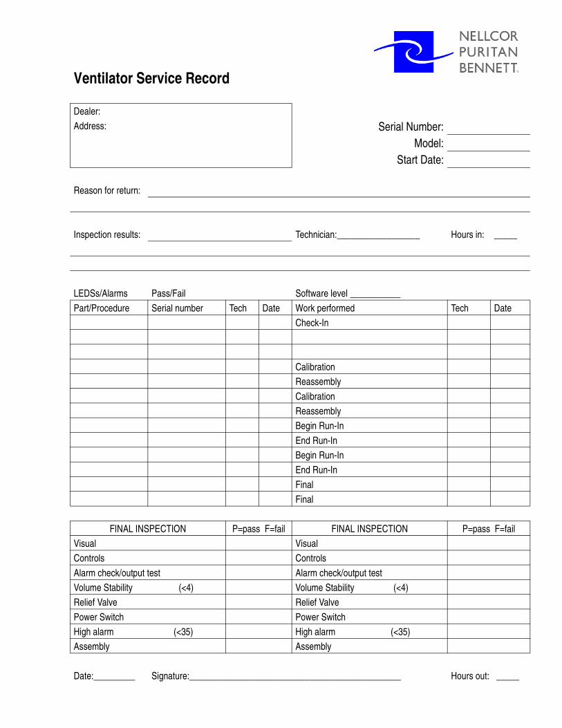
Ventilator Service Record
Dealer:
Address: Serial Number:Model:
Start Date:
Reason for return:
Inspection results: Technician:__________________ Hours in: _____
LEDSs/Alarms Pass/Fail Software level ___________
Part/Procedure Serial number Tech Date Work performed Tech Date
Check-In
Calibration
Reassembly
Calibration
Reassembly
Begin Run-In
End Run-In
Begin Run-In
End Run-In
Final
Final
FINAL INSPECTION P=pass F=fail FINAL INSPECTION P=pass F=fail
Visual Visual
Controls Controls
Alarm check/output test Alarm check/output test
Volume Stability (<4) Volume Stability (<4)
Relief Valve Relief Valve
Power Switch Power Switch
High alarm (<35) High alarm (<35)
Assembly Assembly
Date:_________ Signature:______________________________________________ Hours out: _____

Ventilator Service RecordVentilator Service RecordVentilator Service RecordVentilator Service RecordLP6 Plus, LP10, and LP20 Service Manual
November 2000
Page 5-4Page 5-4Page 5-4Page 5-4
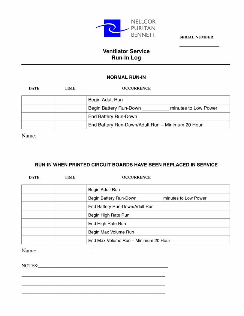
Ventilator ServiceRun-In Log
NORMAL RUN-IN
DATE TIME OCCURRENCE
Name: ______________________________
RUN-IN WHEN PRINTED CIRCUIT BOARDS HAVE BEEN REPLACED IN SERVICE
DATE TIME OCCURRENCE
Name: ______________________________
NOTES:_________________________________________________________________
________________________________________________________________________
________________________________________________________________________
________________________________________________________________________
Begin Adult Run
Begin Battery Run-Down __________ minutes to Low Power
End Battery Run-Down
End Battery Run-Down/Adult Run – Minimum 20 Hour
Begin Adult Run
Begin Battery Run-Down __________ minutes to Low Power
End Battery Run-Down/Adult Run
Begin High Rate Run
End High Rate Run
Begin Max Volume Run
End Max Volume Run – Minimum 20 Hour
SERIAL NUMBER:


November 2000
Page 6-1Page 6-1Page 6-1Page 6-1
6666 Equipment CalibrationEquipment CalibrationEquipment CalibrationEquipment Calibration
Calibration of Model 6960 CalibratorCalibration of Model 6960 CalibratorCalibration of Model 6960 CalibratorCalibration of Model 6960 Calibrator
Note: Perform this procedure at least every three months.
1.1.1.1. Remove the left side cover from a functional LP6 Plus, LP10, orLP20 ventilator that is ready for calibration. Disconnect the inter-nal battery from the harness.
2.2.2.2. Connect the Calibrator to the Internal Battery harness and theCOMMUNICATION PORTCOMMUNICATION PORTCOMMUNICATION PORTCOMMUNICATION PORT of the ventilator.
3.3.3.3. Plug the ventilator into AC power and set the MODEMODEMODEMODE switch toStandby. Set the back panel ON/OFF switch to ON.
4.4.4.4. Monitor the DC voltage across the red and black wires of the two-pin connector on the Calibrator.
5.5.5.5. Remove the bottom cover of the ventilator. Using a non-conductivescrewdriver, adjust R60 on the Power/Motor board such that themonitored voltage is 13.80±0.01 VDC.
6.6.6.6. Adjust the CHARGE VOLTAGE pot on the bottom of the Calibratoruntil the VOLTAGE LED lights solidly.
Note: Do not press the CHARGE button for longer than 10 seconds at a time.If readjustment is necessary, wait three minutes and then repeat thestep.
7.7.7.7. Press and hold the CHARGE button; adjust the CHARGE CUR-RENT pot on the Calibrator until the voltmeter shows 10.50±0.01VDC.
8.8.8.8. Pull the syringe on the Calibrator to the end of its stroke andattach a calibrated pressure meter to the open brass port.
9.9.9.9. Apply pressure with the syringe until the pressure meter indicates50±0.1cmH2O.
10.10.10.10. Adjust the PRESSURE pot on the Calibrator until the PRESSURE50 CM LED lights solidly.
11.11.11.11. The contrast of the display can be set as desired by adjusting thedisplay contrast pot on the Calibrator.

Calibration of Model 6951Right-end TesterCalibration of Model 6951Right-end TesterCalibration of Model 6951Right-end TesterCalibration of Model 6951Right-end TesterLP6 Plus, LP10, and LP20 Service Manual
November 2000
Page 6-2Page 6-2Page 6-2Page 6-2
Calibration of Model 6951Right-end TesterCalibration of Model 6951Right-end TesterCalibration of Model 6951Right-end TesterCalibration of Model 6951Right-end Tester
Note: Perform this procedure at least every six months.
1.1.1.1. Disconnect the tubing from the two pressure gauges. Carefullyremove the face plates.
2.2.2.2. Connect a large syringe and a calibrated pressure meter to thegauge on the left.
3.3.3.3. Apply 12±0.2 cmH2O of pressure as indicated by the calibratedpressure meter.
4.4.4.4. Using the zero screw, adjust the needle of the left pressuregauge so it reads 12.
5.5.5.5. Apply 18±0.2 cmH2O pressure, as indicated by the calibratedpressure meter. The left pressure gauge should indicate 18±2.0cmH2O. Repeat this step for pressure readings of 20 cmH2Oand 25 cmH2O.
6.6.6.6. Connect the syringe and the calibrated pressure meter to thepressure gauge on the right.
7.7.7.7. Apply 100±0.2 cmH2O pressure, as indicated by the calibratedpressure meter.
8.8.8.8. Using the zero screw, adjust the needle of the gauge so it reads100.
9.9.9.9. Remove the syringe and pressure meter.
10.10.10.10. Install the face plates and securely reattach the tubing to thegauges.
11.11.11.11. Check the system for leaks and signs of wear.

November 2000
Page 7-1Page 7-1Page 7-1Page 7-1
7777 Technical BulletinsTechnical BulletinsTechnical BulletinsTechnical BulletinsKeep technical bulletins in this section.

LP6 Plus, LP10, and LP20 Service Manual
November 2000
Page 7-2Page 7-2Page 7-2Page 7-2

November 2000
Page 8-1Page 8-1Page 8-1Page 8-1
8888 Miscellaneous Miscellaneous Miscellaneous Miscellaneous InformationInformationInformationInformation
Keep miscellaneous information in this section.

LP6 Plus, LP10, and LP20 Service Manual
November 2000
Page 8-2Page 8-2Page 8-2Page 8-2


Nellcor Puritan Bennett, Inc., Minneapolis, MN U.S.A.(General) 800.497.4979 (Customer Service) 800.497.4968 (Technical Service) 800.497.3787


![Prospekt LP6 pbV[1]](https://static.fdocuments.us/doc/165x107/54346428219acd5e1a8b53d0/prospekt-lp6-pbv1.jpg)