CEAG emergency lighting systems increase efficiency and reliability

CGLine self-contained luminaires???
CEAG LP-STARCompact emergency lighting power supply with STAR technology
LP-STARSafe and cost efficient operation with installation per area

2 CEAG LP-STAR EmERGEnCy LiGhTinG PowER SuPPLy www.ceag.de
LP-STAR emergency lighting power supply in a compact designInstallation example
Ethernet
EthernetTCP/IP
CGVision PC
CG-S bus
CG-S bus
Automatic Test System AT-S+
Automatic Test System AT-S+
Central battery system ZB-S
Central battery system ZB-S
IP router
IP router
Building 2
Building 1
Example connection to the central visualisation system CG Vision
Building 3
Ethernet
Ethernet
Ethernet
Ethernet
LP-STAR
LP-STAR
LP-STAR
LP-STAR
LP-STAR
LP-STAR
LP-STAR

www.ceag.de CEAG LP-STAR EmERGEnCy LiGhTinG PowER SuPPLy 3
LP-STAR emergency lighting power supply in a compact designFeatures
LP-STAR is especially recommended in case of the separate supply of emergency lighting systems of individual fi re areas to save on installation costs incurred by installing E30 cabling to cover different fi re areas.
The LP-STAR System supplies reliable power to the escape luminaires and exit sign luminaires (230V AC/220 V DC) according to EN 50171 and BGV A3. It is suitable for emergency lighting systems according to DIN VDE 0100-718, DIN EN 50172 and E DIN VDE 0108-100.
The system performs an automatic self-check and monitors all CG-S luminaires connected (up to 20 luminaires per circuit) simply through a feed line. The circuit type of each connected CG-S luminaire can be programmed freely in the 50 Hz or 60 Hz supply network with the control module based on the STAR technology. This means that the same power circuit is used for mixed operation including maintained light, switched maintained light and non-maintained light, all this without an additional data cable!
The control module including a non-volatile program memory as well as a big graphical display that monitors and controls the LP-STAR device and checks all functions of the connected emergency luminaires according to EN 62034 and it reports the operating states of the entire system. The integrated search function detects all luminaires addressed during installation automatically. A central monitoring system can be connected using the optional bus interface.
The main scope for the protection of electrical rooms is the protection of the environment against the hazards involved with technical devices, transformer stations and switching stations of over 1 kV. At the same time, for example in case of fi re, the operation of safety-relevant systems, central battery systems and fi xed power generators must be maintained for a specifi c period of time.
The LP-STAR System was designed to meet the requirements concerning batteries and these have been verifi ed according to EN 60950 and EN 50272-2.
Features• No special requirements
concerning the housing on functionality in case of installation in separate fi re areas
• Cost savings as E30 wiring is not required because devices are installed in separate fi re areas
• Natural ventilation is generally suffi cient due to the closed form and low capacity of batteries
• Additional safety even in case of fi re due to the decentralised arrangement of systems
• Simple operation and commissioning based on a smart programming and operating plan
• 230V AC / 220V DC supply voltage selectable to power the escape luminaires and exit sign luminaires to comply with architectural issues
• Standard integrated phase monitor for monitoring general power supply conditions
• Additional phase monitor input including line monitoring for an external phase monitor
• Standard eight digital 230 V input channels for switching each luminaire separately, for example, freely programmable
Simple installation and reliable power supply
• Optional webmodule for the automatic monitoring of LP-STAR according to EN 62034
• Optional CG-S interface for connecting to the CG-S bus for CGVision or master/slave operation for connecting several LP-STAR devices
• Shorter inspection time using the CEWA GUARD technology, automatic function monitoring of up to 20 luminaires per circuit
• Reduced installation costs due to the STAR technology, freely programmable mixed operation of switching modes per luminaire in a single circuit without an additional data cable
• Automatic luminaire search function
• Plain text display at the control module for all luminaires
• Flexible data memory for the test log and device confi guration using the Secure Digital card
• Absence of retroactive effect of different circuits in case of a short-circuit due to the automatic, selective shut-off function
• EoL shut-off, programmable as standard
4 CEAG LP-STAR EmERGEnCy LiGhTinG PowER SuPPLy www.ceag.de
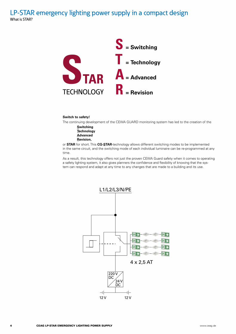
LP-STAR emergency lighting power supply in a compact designWhat is STAR?
Switch to safety!The continuing development of the CEWA GUARD monitoring system has led to the creation of the Switching Technology Advanced Revision,or STAR for short. This CG-STAR-technology allows different switching modes to be implemented in the same circuit, and the switching mode of each individual luminaire can be re-programmed at any time.
As a result, this technology offers not just the proven CEWA Guard safety when it comes to operating a safety lighting system, it also gives planners the confidence and flexibility of knowing that the sys-tem can respond and adapt at any time to any changes that are made to a building and its use.
S = Switching
T = Technology
A = Advanced
R = Revision
220 VDC
24 VDC
12 V12 V
4 x 2,5 AT
L1/L2/L3/N/PE

www.ceag.de CEAG LP-STAR EmERGEnCy LiGhTinG PowER SuPPLy 5
LP-STAR emergency lighting power supply in a compact designSTAR technology – easy planning
DS
DSBS
BS
DLS
DLS
DS
DSBS
BS
DLS
DLS
Your Advantages:The number of outgoing circuits needed can be sharply reduced, since continuously operating, stand-by and switchable permanent lighting can be realised in one common circuit.
This allows the use of shorter cable distances, reduces installation costs and minimises the effects of burning materials. Any mode of operation can be assigned at a later date – without encroachment in the lighting installation. This enables simple project planning without having to take all possible types of operation into account.
As with CEWA GUARD technology, the patented STAR technology requires no additional data cable to the luminaires.
Conventional Installation:Maintained light 1 (DS)Non-maintained light 1 (BS)Non-maintained light 2 (BS)Maintained light 2 (DS)Switched maintai-ned light 1 (DLS)Switched maintained light (DLS)
• Each type of switching mode requires two circuits
• Only one type of switching mode is possible per circuit
• Any later modifi cations involve a large amount of work and expense
ZB-S Installation withSTAR-Technology:All types of switching modesAll types of switching modes
• Only two outgoing circuits for all types of switching modes
• Maintained light, non-main-tained light and switched maintained light are possible in one common circuit
• Later circuit modifi cations do not pose any problems
6 CEAG LP-STAR EmERGEnCy LiGhTinG PowER SuPPLy www.ceag.de
LP-STAR emergency lighting power supply in a compact designConstruction
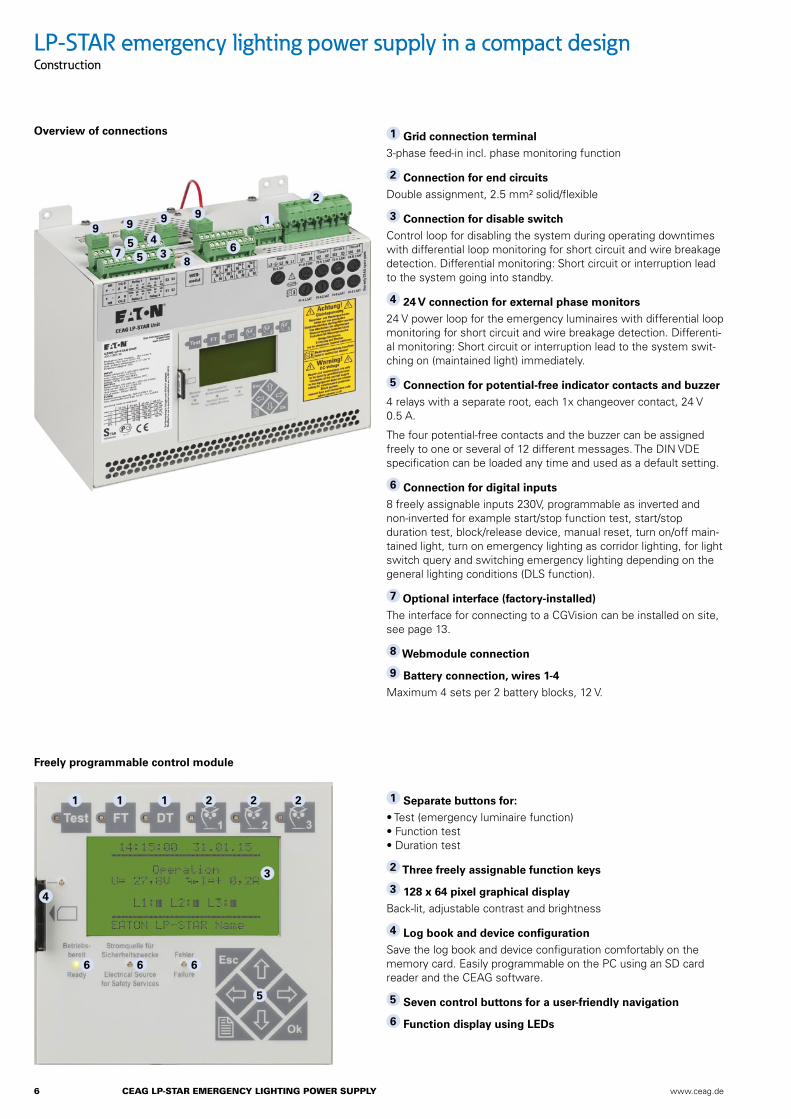
1 Grid connection terminal3-phase feed-in incl. phase monitoring function
2 Connection for end circuitsDouble assignment, 2.5 mm² solid/flexible
3 Connection for disable switchControl loop for disabling the system during operating downtimes with differential loop monitoring for short circuit and wire breakage detection. Differential monitoring: Short circuit or interruption lead to the system going into standby.
4 24 V connection for external phase monitors24 V power loop for the emergency luminaires with differential loop monitoring for short circuit and wire breakage detection. Differenti-al monitoring: Short circuit or interruption lead to the system swit-ching on (maintained light) immediately.
5 Connection for potential-free indicator contacts and buzzer4 relays with a separate root, each 1x changeover contact, 24 V 0.5 A.
The four potential-free contacts and the buzzer can be assigned freely to one or several of 12 different messages. The DIN VDE specification can be loaded any time and used as a default setting.
6 Connection for digital inputs8 freely assignable inputs 230V, programmable as inverted and non-inverted for example start/stop function test, start/stop duration test, block/release device, manual reset, turn on/off main-tained light, turn on emergency lighting as corridor lighting, for light switch query and switching emergency lighting depending on the general lighting conditions (DLS function).
7 Optional interface (factory-installed)The interface for connecting to a CGVision can be installed on site, see page 13.
8 Webmodule connection
9 Battery connection, wires 1-4Maximum 4 sets per 2 battery blocks, 12 V.
Freely programmable control module
Overview of connections
1 Separate buttons for:• Test (emergency luminaire function) • Function test • Duration test
2 Three freely assignable function keys
3 128 x 64 pixel graphical displayBack-lit, adjustable contrast and brightness
4 Log book and device configurationSave the log book and device configuration comfortably on the memory card. Easily programmable on the PC using an SD card reader and the CEAG software.
5 Seven control buttons for a user-friendly navigation
6 Function display using LEDs
1 1 1
4
2 2 2
5
3
6 6 6
1
4
2
55
3 68
7
9 9 9 9
www.ceag.de CEAG LP-STAR EmERGEnCy LiGhTinG PowER SuPPLy 7
LP-STAR emergency lighting power supply in a compact designConstruction
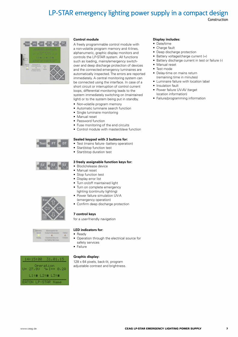
Control moduleA freely programmable control module with a non-volatile program memory and 4-lines, alphanumeric, graphic display monitors and controls the LP-STAR system. All functions such as loading, mains/emergency switch-over and deep discharge protection of devices and the connected emergency luminaires are automatically inspected. The errors are reported immediately. A central monitoring system can be connected using the interface. In case of a short circuit or interruption of control current loops, differential monitoring leads to the system immediately switching on (maintained light) or to the system being put in standby.• Non-volatile program memory• Automatic luminaire search function• Single luminaire monitoring• Manual reset• Password function• Fuse monitoring of the end circuits • Control module with master/slave function
Sealed keypad with 3 buttons for:• Test (mains failure - battery operation) • Start/stop function test• Start/stop duration test
3 freely assignable function keys for:• Block/release device• Manual reset• Stop function test• Display error list• Turn on/off maintained light • Turn on complete emergency
lighting (continuity lighting)• Power failure simulation UV-A
(emergency operation)• Confirm deep discharge protection
7 control keys for a user-friendly navigation
LED indicators for:• Ready • Operation through the electrical source for
safety services• Failure
Graphic display: 128 x 64 pixels, back-lit, program adjustable contrast and brightness.
Display includes:• Date/time • Charge fault• Deep discharge protection • Battery voltage/charge current (+)• Battery discharge current in test or failure (-)• Manual reset• Test mode• Delay-time on mains return
(remaining time in minutes)• Luminaire failure with location label• Insulation fault• Power failure UV-AV (target
location information)• Failure/programming information
14:15:00 31.01.15 ČČČČČČČČČČČČČČČČČČČČ Operation U= 27,8V ĀāI=+ 0,2A L1:Ć L2:Ć L3:Ć čččččččččččččččččččč EATON LP-STAR Name
8 CEAG LP-STAR EmERGEnCy LiGhTinG PowER SuPPLy www.ceag.de
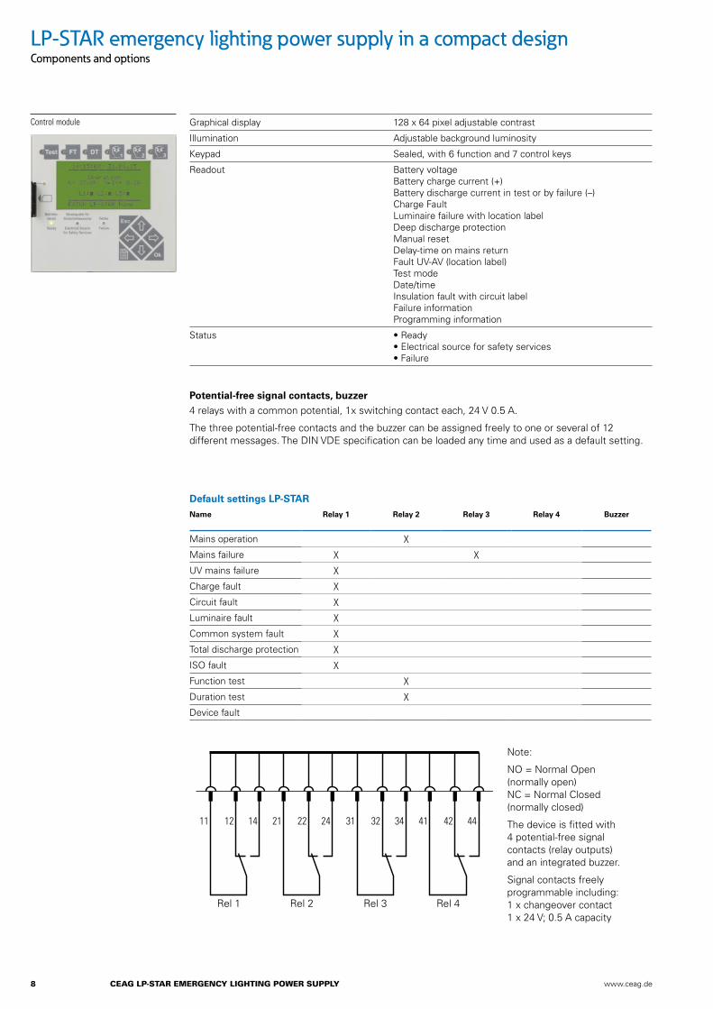
Graphical display 128 x 64 pixel adjustable contrast
Illumination Adjustable background luminosity
Keypad Sealed, with 6 function and 7 control keys
Readout Battery voltage Battery charge current (+) Battery discharge current in test or by failure (–) Charge Fault Luminaire failure with location label Deep discharge protection Manual reset Delay-time on mains return Fault UV-AV (location label) Test mode Date/time Insulation fault with circuit label Failure information Programming information
Status • Ready • Electrical source for safety services • Failure
Potential-free signal contacts, buzzer4 relays with a common potential, 1x switching contact each, 24 V 0.5 A.
The three potential-free contacts and the buzzer can be assigned freely to one or several of 12 different messages. The DIN VDE specification can be loaded any time and used as a default setting.
Default settings LP-STAR Name Relay 1 Relay 2 Relay 3 Relay 4 Buzzer
Mains operation X
Mains failure X X
UV mains failure X
Charge fault X
Circuit fault X
Luminaire fault X
Common system fault X
Total discharge protection X
ISO fault X
Function test X
Duration test X
Device fault
Note:
NO = Normal Open (normally open) NC = Normal Closed (normally closed)
The device is fitted with 4 potential-free signal contacts (relay outputs) and an integrated buzzer.
Signal contacts freely programmable including: 1 x changeover contact 1 x 24 V; 0.5 A capacity
LP-STAR emergency lighting power supply in a compact designComponents and options
Control module
11 12 14 21 22 24 31 32 34 41 42 44
Rel 1 Rel 2 Rel 3 Rel 4
www.ceag.de CEAG LP-STAR EmERGEnCy LiGhTinG PowER SuPPLy 9
LP-STAR emergency lighting power supply in a compact designComponents and options
Ordering details Type Model Order No.
SD card SD card formatted for LP-STAR 40071347911
SD card reader SD card reader for USB port 40064070561
Software Software for the external programming of the LP-STAR device using a PC
40071347152
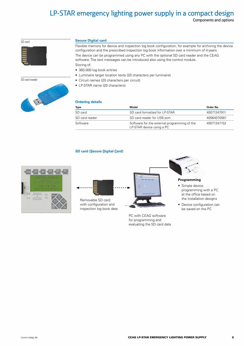
Secure Digital card
Flexible memory for device and inspection log book confi guration, for example for archiving the device confi guration and the prescribed inspection log book information over a minimum of 4 years.The device can be programmed using any PC with the optional SD card reader and the CEAG software. The text messages can be introduced also using the control module.Storing of:• 360.000 log book entries• Luminaire target location texts (20 characters per luminaire)• Circuit names (20 characters per circuit)• LP-STAR name (20 characters)
SD card
SD card reader
SD card (Secure Digital Card)
Removable SD card with confi guration and inspection log book data
PC with CEAG software for programming and evaluating the SD card data
Programming
• Simple device programming with a PC at the offi ce based on the installation designs
• Device confi guration can be saved on the PC
10 CEAG LP-STAR EmERGEnCy LiGhTinG PowER SuPPLy www.ceag.de
LP-STAR emergency lighting power supply in a compact designComponents and options
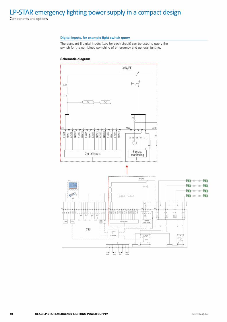
Digital inputs, for example light switch query
The standard 8 digital inputs (two for each circuit) can be used to query the switch for the combined switching of emergency and general lighting.
+ -
+ - + - + - + -
+24V CG-S Digital inputs
Controller
CSU
3-phasemonitoring
3/N/PE
CM4-24U
N L
B+ B- B+ B-
24V DC
220V DC
X501
CGVision
UH+
UH+
UH-
UH-
CG-S
-B
CG-S
-B
CG-S
-A
CG-S
-A
Rel. 1 Rel. 2 Rel. 3
String 1 String 2 String 3 String 4
Rel. 4
11 12 14 21 22 24 31 32 34 41 42 44 S1 S2 S3 S4 L-DL
S1
N-D
LS1
L-DL
S2
N-D
LS2
L-DL
S3
N-D
LS3
L-DL
S4
N-D
LS4
L-DL
S5
N-D
LS5
L-DL
S6
N-D
LS6
L-DL
S7
N-D
LS7
L-DL
S8
N-D
LS8
X101 X100
PE
X102
CNV
t
L3 PE L2 N L1
U1 01 U2 02 U3 03 U4 04
Schematic diagram
www.ceag.de CEAG LP-STAR EmERGEnCy LiGhTinG PowER SuPPLy 11
+
12
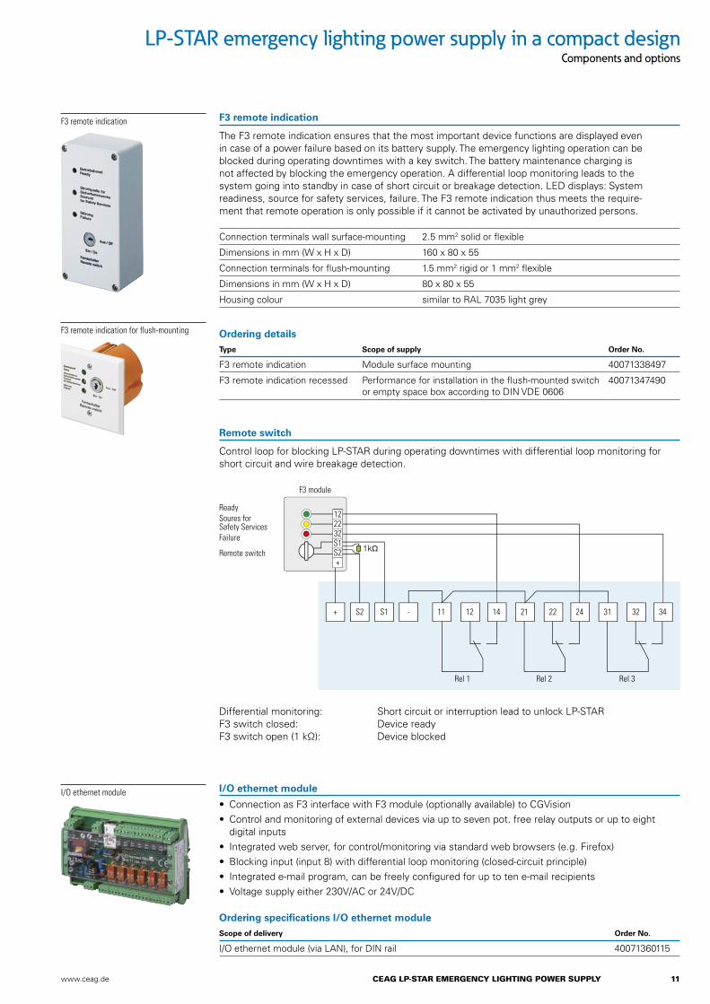
F3 module
Rel 1 Rel 2 Rel 3
ReadySoures forSafety ServicesFailure
Remote switch
2232S1S2+
S2 S1 - 11 12 14 21 22 24 31 32 34
LP-STAR emergency lighting power supply in a compact designComponents and options
Ordering details Type Scope of supply Order No.
F3 remote indication Module surface mounting 40071338497
F3 remote indication recessed Performance for installation in the flush-mounted switch or empty space box according to DIN VDE 0606
40071347490
Differential monitoring: Short circuit or interruption lead to unlock LP-STARF3 switch closed: Device readyF3 switch open (1 kΩ): Device blocked
F3 remote indication
The F3 remote indication ensures that the most important device functions are displayed even in case of a power failure based on its battery supply. The emergency lighting operation can be blocked during operating downtimes with a key switch. The battery maintenance charging is not affected by blocking the emergency operation. A differential loop monitoring leads to the system going into standby in case of short circuit or breakage detection. LED displays: System readiness, source for safety services, failure. The F3 remote indication thus meets the require-ment that remote operation is only possible if it cannot be activated by unauthorized persons.
Remote switch
Control loop for blocking LP-STAR during operating downtimes with differential loop monitoring for short circuit and wire breakage detection.
F3 remote indication
Connection terminals wall surface-mounting 2.5 mm2 solid or flexible
Dimensions in mm (W x H x D) 160 x 80 x 55
Connection terminals for flush-mounting 1.5 mm2 rigid or 1 mm2 flexible
Dimensions in mm (W x H x D) 80 x 80 x 55
Housing colour similar to RAL 7035 light grey
F3 remote indication for flush-mounting
Ordering specifications I/O ethernet module Scope of delivery Order No.
I/O ethernet module (via LAN), for DIN rail 40071360115
I/O ethernet module I/O ethernet module
• Connection as F3 interface with F3 module (optionally available) to CGVision• Control and monitoring of external devices via up to seven pot. free relay outputs or up to eight
digital inputs • Integrated web server, for control/monitoring via standard web browsers (e.g. Firefox) • Blocking input (input 8) with differential loop monitoring (closed-circuit principle)• Integrated e-mail program, can be freely configured for up to ten e-mail recipients• Voltage supply either 230V/AC or 24V/DC

12 CEAG LP-STAR EmERGEnCy LiGhTinG PowER SuPPLy www.ceag.de
Three-phase monitoring
Three-phase monitoring is used for monitoring the distributors of general lighting systems. In case of a phase failure, the component switches a relay contact and interrupts the standard electronic 24 V power loop in the LP-STAR device.
The emergency luminaires in non-maintained mode are switched to mains operation as long as the LP-STAR system is supplied by mains voltage.
Current loop
24V current loop for emergency lighting request with differential loop monitoring for short circuit and wire breakage detection.
Dimensions in mm (W x H x D) 85 x 52.5 x 65
Housing Plastic, red
Connection terminals 2.5 mm2 rigid or flexible
Type of mounting DIN mounitng rail
Contact 0.5 A/24 V AC/DC, 1 x open contact, 1 x change-over contact
Trigger threshold U< 85 % UN
Grid size 3 units
Ordering details Type Scope of supply Order No.
Three-phase monitoring Module ready for mounting 40071343430
Three-phase monitoring
Differential monitoring: Short circuit or interruption lead to the system immediately switching on (maintained light)
Phase monitor switch closed (1 kΩ): Normal system mode
LP-STAR emergency lighting power supply in a compact designComponents and options
UV-AV2L1L2L3N
1 2 3 S/S
3PH
UV-AV1
LP-STARL1L2L3N
Resistor1 k
S3/S4
1 2 3 S/S
3PH

www.ceag.de CEAG LP-STAR EmERGEnCy LiGhTinG PowER SuPPLy 13
Ordering detailsType Scope of supply Order No.
CG-S Bus Interface Plug-in card* 40071071178
* Attention: The CG-S Bus Interface must be installed by the manufacturer. The module can be installed later on site only with the replace-ment of the entire CSU module.
LP-STAR emergency lighting power supply in a compact designComponents and options
CGVision Package III
CGVision Package III application example
CGVision PC
USB
Ethernet
CG-S bus
CG-S devices through the CG-S/USB interface, connectable even mixed
CGVision Package III (Basic or Pro) includes the CG-S/USB inter-face (USB box), for connecting the CG-S bus-based emergency luminaire systems like the LP-STAR, ZB-S and AT-S+ to the CGVision visualisation software using a standard bus cable and an optional CG-S Bus Interface.
Up to 480 devices of the LP-STAR, ZB-S or AT-S+ systems can be connected, even in mixed mode. However, systems must be assigned to their own device groups in CGVision.
The bus cable can be extended with an optionally available repeater or router.
The CGVision Package III also includes all dongle licences for EGA devices (ZB96, EuroZB.1, GVL24.1, CG48 or ZVL220), CGLine or Ethernet I/O module on CGVision.CG-S bus• Max. bus length: 900 m
• The bus length can be extended using a router/repeater
• Double terminated Bus
• No stub lines allowed
• Recommended cable: JY (ST) Y 4 x 2 x 0.8 mm² Ø twisted pair (double twisted pair), shielded
• Termination resistor: 105 Ω on both sides
CG-S/USB Interface
24 V
ZB-S
EthernetTCP/IP
AT-S+
AT-S+ AT-S+
ZB-S
ZB-S
F3 remote indication
Repeater or router for increasing the distance > 900 m cable
I/O-Ethernet module
LP-STAR
LP-STAR

14 CEAG LP-STAR EmERGEnCy LiGhTinG PowER SuPPLy www.ceag.de
Ordering details Type Scope of supply Order No.
Software PC software for LP-STAR for alternative programming of the system configuration on PC
40071347152
PC programming software LP-STAR
Programming software for pre-configured LP-Star memory cards for quick pre-programming on the PC and for easy reading and processing of the inspection log book memory. All data can be saved on the memory card and hard disk for documentation.
Prints for documentation: Detailed prints of programmed system configuration with the following information:
• Individual device name (20 characters) + 100 characters of additional information
• Date and time of automatic duration test incl. Distance in months
• Date and time of automatic function test incl. Distance in days
• Manual reset: Yes/No
• Delay in mains return: 0-99 min
• LON switch: Yes/No
• Capacity in Ah
• Rated operating time in h
• Operating limit time in %
• Assignments of the 4 relays
• Assignments of the 3 function keys
• Assignments of the 8 optional inputs
Detailed print of the programmed circuits (wiring diagrams) with the following information for each circuit:
• Circuit/ SKU number and type
• Individual circuit name
• Monitoring type for circuit
• Switch type for circuit
• Number of luminaires
• Address and individual name of each luminaire
• Circuit type for each luminaire
Print of inspection log book with following options:
• Fault events (35 various fault events selectable separately or fully)
• Inspection log book period (from – to for date and time)
• Individual comment per print
• For luminaire failure: Information on individual luminaire and circuit names
LP-STAR emergency lighting power supply in a compact designComponents and options

www.ceag.de CEAG LP-STAR EmERGEnCy LiGhTinG PowER SuPPLy 15
LP-STAR emergency lighting power supply in a compact designComponents and options
Ordering details Type Scope of supply Order No.
Webmodule LP-STAR Module for DIN rail mounting, incl. connection without RJ45 patch cable, mounted ex works
40071361188
Webmodule LP-STAR Module for DIN rail mounting, incl. connection without RJ45 patch cable, for retrofi tting
40071361187
Webmodule LP-STAR
Webmodule LP-STAR for visualisation and monitoring an LP-STAR device on the local Ethernet (LAN) or Internet (WWW) with a conventional WEB browser. Access to the webmodule via internet (WWW) must be appropriately administered and set up on site by a competent IT department. Integrated mail program for convenient, event-related error notifi cation via email, for up to 5 email recipients. 1 web-module is required for each LP-STAR device.
• Simple menu navigation
• Any type of display devices can be used with a WEB browser, for example notebook, tablet PC, IPad or smartphone
• Complete visualisation and monitoring of an LP-STAR device through the local Ethernet (LAN) with a regular WEB browser, no additional software required for all functions
• Retrieving and indicating all current operating states
• Localised fault indicators for every emergency luminaire circuit and luminaires with target location information in plain text connected to a function test
• Continuous up-to-date information on charging unit and battery
• Parallel access from various PC workstations to a webmodule possible (max. 8)
• Integrated email program for each webmodule for convenient error notifi cation via email
• Adjustable email dispatch acc. to type of error or function test
• Up to 5 email recipients programmable
• Adjustable update cycle for web browser via the webmodule
• Authenticated access via administrator account with password protection
• Confi gurable guest account for restricted access with password protection
• Static or dynamic (DHCP) IP addressing possible
• Any number of webmodules operable in parallel
• Overview of all active webmodules on the local Ethernet with status display and hyperlink function
• Independent parallel operation of a CGVision visualisation possible
Webmodule LP-STAR
Device supply voltage 24 V DC
Rated power < 1.5 W
Connection RJ45
Degree of protection IP20
Weight 0.1 kg
Dimensions 90 x 35 x 58
Housing Polycarbonate
Connection example:
Example: Device status
Example: Circuit status
Direct access using the IP address, for ex.: 192.168.100.5
LAN with HTTP through TCP
IP: 192.168.100.5
IP: 192.168.100.6
16 CEAG LP-STAR EmERGEnCy LiGhTinG PowER SuPPLy www.ceag.de
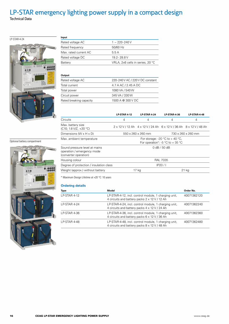
Ordering details Type Model Order No.
LP-STAR 4-12 LP-STAR-4-12, incl. control module, 1 charging unit, 4 circuits and battery packs 2 x 12 V / 12 Ah
40071362120
LP-STAR 4-24 LP-STAR-4-24, incl. control module, 1 charging unit, 4 circuits and battery packs 4 x 12 V / 24 Ah
40071362240
LP-STAR 4-36 LP-STAR-4-36, incl. control module, 1 charging unit, 4 circuits and battery packs 6 x 12 V / 36 Ah
40071362360
LP-STAR 4-48 LP-STAR-4-48, incl. control module, 1 charging unit, 4 circuits and battery packs 8 x 12 V / 48 Ah
40071362480
LP-STAR 4-12 LP-STAR 4-24 LP-STAR-4-36 LP-STAR-4-48
Circuits 4 4 4 4
Max. battery size (C10; 1.8 V/Z, +20 °C) 2 x 12 V / 12 Ah 4 x 12 V / 24 Ah 6 x 12 V / 36 Ah 8 x 12 V / 48 Ah
Dimensions (W x H x D) 550 x 260 x 260 mm 730 x 260 x 260 mm
Max. ambient temperature For storage: -20 °C to + 40 °C, For operation*: -5 °C to + 35 °C
Sound pressure level at mains operation / emergency mode (converter operation)
0 dB / 50 dB
Housing colour RAL 7035
Degree of protection / insulation class IP20 / I
Weight (approx.) without battery 17 kg 21 kg
* Maximum Design Lifetime at +20 °C: 10 years
LP-STAR-4-24
Optional battery compartment
LP-STAR emergency lighting power supply in a compact designTechnical Data
Input
Rated voltage AC 1 ~ 220-240 V
Rated frequency 50/60 Hz
Max. rated current AC 5.5 A
Rated voltage DC 19.2 - 28.8 V
Battery VRLA, 2x6 cells in series, 20 °C
Output
Rated voltage AC 220-240 V AC / 220 V DC constant
Total current 4.7 A AC / 2.45 A DC
Total power 1080 VA / 540 W
Circuit power 345 VA / 330 W
Rated breaking capacity 1500 A @ 300 V DC

www.ceag.de CEAG LP-STAR EmERGEnCy LiGhTinG PowER SuPPLy 17
Battery Rated capacity
AhK10, 1,8 V/Z, +20 °CDimensions
of one battery L x W x H (mm)
Number of batteries UB = 12 V pieces
Total weight of all batteries
(kg)
10 Y: 12 Ah 152 x 98 x 102 max. 8 4 pieces: 15.258 pieces: 30.50
Battery ordering details Type Model Order No.
12 V/12 Ah Battery block, period of use: 10 years 40066071147
Period of use specified for a max. battery temperature of +20 °C
Fuse ordering details Type Model Order No.
Final circuit fuses 2.5 AT / 250 V (packaging unit 10 pieces) 400713611235
Mains feed-in circuits 6.3 AT / 250 V (packaging unit 10 pieces) 400713611234
Accessories ordering details Type Model Order No.
Clamping gland set, 28 pieces 4 x M25, 18 x M20, 6 x M16 40071361159
LP-STAR-4-24
LP-STAR emergency lighting power supply in a compact designTechnical Data
1 = 4 x M25
2 = 18 x M20
3 = 6 x M16
Pre-cut cable entries LP-STAR
1
2
3
18 CEAG LP-STAR EmERGEnCy LiGhTinG PowER SuPPLy www.ceag.de
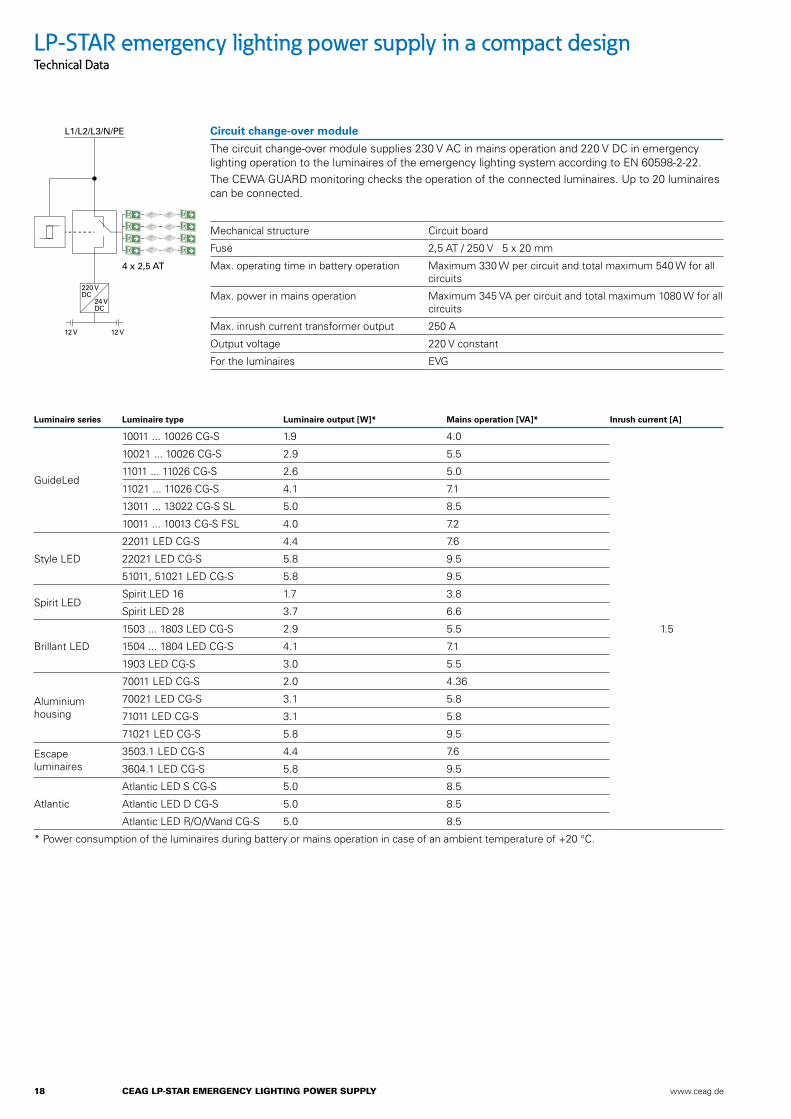
Luminaire series Luminaire type Luminaire output [W]* Mains operation [VA]* Inrush current [A]
GuideLed
10011 ... 10026 CG-S 1.9 4.0
1.5
10021 ... 10026 CG-S 2.9 5.5
11011 ... 11026 CG-S 2.6 5.0
11021 ... 11026 CG-S 4.1 7.1
13011 ... 13022 CG-S SL 5.0 8.5
10011 ... 10013 CG-S FSL 4.0 7.2
Style LED
22011 LED CG-S 4.4 7.6
22021 LED CG-S 5.8 9.5
51011, 51021 LED CG-S 5.8 9.5
Spirit LED Spirit LED 16 1.7 3.8
Spirit LED 28 3.7 6.6
Brillant LED
1503 ... 1803 LED CG-S 2.9 5.5
1504 ... 1804 LED CG-S 4.1 7.1
1903 LED CG-S 3.0 5.5
Aluminium housing
70011 LED CG-S 2.0 4.36
70021 LED CG-S 3.1 5.8
71011 LED CG-S 3.1 5.8
71021 LED CG-S 5.8 9.5
Escape luminaires
3503.1 LED CG-S 4.4 7.6
3604.1 LED CG-S 5.8 9.5
Atlantic
Atlantic LED S CG-S 5.0 8.5
Atlantic LED D CG-S 5.0 8.5
Atlantic LED R/O/Wand CG-S 5.0 8.5
* Power consumption of the luminaires during battery or mains operation in case of an ambient temperature of +20 °C.
Circuit change-over module
The circuit change-over module supplies 230 V AC in mains operation and 220 V DC in emergency lighting operation to the luminaires of the emergency lighting system according to EN 60598-2-22. The CEWA GUARD monitoring checks the operation of the connected luminaires. Up to 20 luminaires can be connected.
Mechanical structure Circuit board
Fuse 2,5 AT / 250 V 5 x 20 mm
Max. operating time in battery operation Maximum 330 W per circuit and total maximum 540 W for all circuits
Max. power in mains operation Maximum 345 VA per circuit and total maximum 1080 W for all circuits
Max. inrush current transformer output 250 A
Output voltage 220 V constant
For the luminaires EVG
LP-STAR emergency lighting power supply in a compact designTechnical Data
220 VDC
24 VDC
12 V12 V
4 x 2,5 AT
L1/L2/L3/N/PE

www.ceag.de CEAG LP-STAR EmERGEnCy LiGhTinG PowER SuPPLy 19
Connection cable/W for the luminaires with:
International term
Lamp cap
EVG Type EVG ...
Lamp load in [W] Battery operation P [W] at a luminous flux �E/�Rated = 75 %
Mains operation S [VA]
Inrush current [A]
T 16 G5 13.3 ... 4 4.5 8 3
13.3 ... 6 5.5 12 3
13.3 ... 8 7.25 16 3
13.3 ... 13 12.5 23 3
TC-SEL 2G7 13.3 ... 5 5.0 10 3
13.3 ... 7 6.4 13 3
13.3 ... 9 8.0 16 3
13.3 ... 11 10.0 18 3
TC-DEL G24q-1 13.3 ... 10 8.5 16 3
13.3 ... 13 12.5 23 3
TC-TEL GX24q-1 13.3 ... 13 12.5 23 3
T 26 G13 18 ... 18 16.0 30 8
TC-F 2G10 18 ... 18 16.0 30 8
TC-L 2G11 18 ... 18 16.0 30 8
TC-DEL G24q-2 18C ... 18 16.0 30 8
TC-TEL GX24q-2 18C ... 18 16.0 30 8
Continuous output = start output
N-EVG 54 W V-CG-S Rated value N-EVG ... V-CG-S in case of mains and battery operation
Term T5 T5 T5 T5 T5 T5
Lamp cap G5 G5 G5 G5 G5 G5
Type N-EVG ... V-CG-S 14 / 21 / 28 / 35 W
14 / 21 / 28 / 35 W
14 / 21 / 28 / 35 W
14 / 21 / 28 / 35 W
24/39 W 24/39 W
Lamp load [W] 14 21 28 35 24 39
Battery operation, incl. converter efficiency [W] in switch position (luminous flux �E/�Rated in %)
100 % 21 28 39 47 34 49
90 % 18 26 34 41 31 44
80 % 17 23 31 36 26 39
70 % 15 21 28 34 23 34
60 % 13 18 26 28 21 31
50 % 12 16 23 26 18 28
40 % 10 14 21 23 17 26
30 % 9 13 18 21 15 23
Power consumption [VA] 22 30 38 46 32 49
Inrush current [A] 10
System power lamp + EVG acc. EN 50294 [W]
16 23 30 37 25 41
LP-STAR emergency lighting power supply in a compact designTechnical Data
20 CEAG LP-STAR EmERGEnCy LiGhTinG PowER SuPPLy www.ceag.de
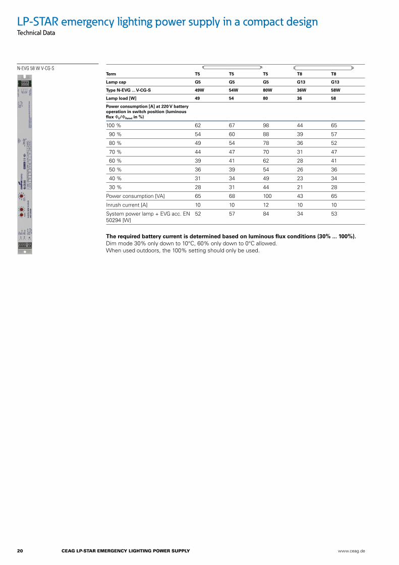
N-EVG 58 W V-CG-STerm T5 T5 T5 T8 T8
Lamp cap G5 G5 G5 G13 G13
Type N-EVG ... V-CG-S 49W 54W 80W 36W 58W
Lamp load [W] 49 54 80 36 58
Power consumption [A] at 220 V battery operation in switch position (luminous flux �E/�Rated in %)
100 % 62 67 98 44 65
90 % 54 60 88 39 57
80 % 49 54 78 36 52
70 % 44 47 70 31 47
60 % 39 41 62 28 41
50 % 36 39 54 26 36
40 % 31 34 49 23 34
30 % 28 31 44 21 28
Power consumption [VA] 65 68 100 43 65
Inrush current [A] 10 10 12 10 10
System power lamp + EVG acc. EN 50294 [W]
52 57 84 34 53
The required battery current is determined based on luminous flux conditions (30% ... 100%). Dim mode 30% only down to 10°C, 60% only down to 0°C allowed. When used outdoors, the 100% setting should only be used.
LP-STAR emergency lighting power supply in a compact designTechnical Data
www.ceag.de CEAG LP-STAR EmERGEnCy LiGhTinG PowER SuPPLy 21
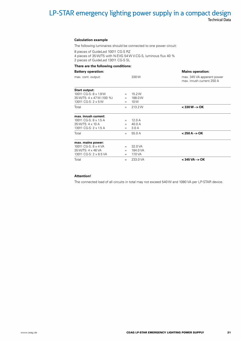
There are the following conditions:
Battery operation: Mains operation:
max. cont. output: 330 W max. 345 VA apparent powermax. inrush current 250 A
Start output: 10011 CG-S: 8 x 1.9 W 35 W/T5: 4 x 47 W (100 %) 13011 CG-S: 2 x 5 W
= = =
15.2 W 188.0 W 10 W
Total = 213.2 W < 330 W --> OK
max. inrush current: 10011 CG-S: 8 x 1.5 A 35 W/T5: 4 x 10 A 13011 CG-S: 2 x 1.5 A
= = =
12.0 A 40.0 A 3.0 A
Total = 55.0 A < 250 A --> OK
max. mains power: 10011 CG-S: 8 x 4 VA 35 W/T5: 4 x 46 VA 13011 CG-S: 2 x 8.5 VA
= = =
32.0 VA 184.0 VA 17.0 VA
Total = 233.0 VA < 345 VA --> OK
Calculation example
The following luminaires should be connected to one power circuit:
8 pieces of GuideLed 10011 CG-S RZ 4 pieces of 35 W/T5 with N-EVG 54 W V-CG-S, luminous flux 40 % 2 pieces of GuideLed 13011 CG-S SL
LP-STAR emergency lighting power supply in a compact designTechnical Data
Attention!
The connected load of all circuits in total may not exceed 540 W and 1080 VA per LP-STAR device.
22 CEAG LP-STAR EmERGEnCy LiGhTinG PowER SuPPLy www.ceag.de
+–
H2 O2
Pb PbO 2
+– H2O
O2
Pb PbO 2
UI
I
U
t1 min. 1 min.
1,6 V/cell
2,4 V/cell
2,3 V/cell
Deep discharge protection
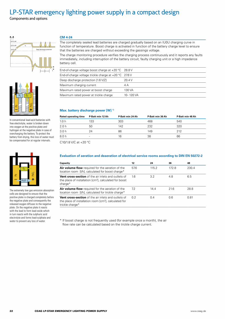
CM 4-24
The completely sealed lead batteries are charged gradually based on an IU0U charging curve in function of temperature. Boost charge is activated in function of the battery charge level to ensure that the batteries are charged without exceeding the gassings voltage.The charge monitoring procedure verifies the charging process continuously and it reports any faults immediately, including interruption of the battery circuit, faulty charging unit or a high impedance battery cell.
In conventional lead-acid batteries with free electrolyte, water is broken down into oxygen at the positive plate and hydrogen at the negative plate in case of overcharging the battery. To protect the battery from drying, this loss of water must be compensated for at regular intervals.
The extremely low gas emission absorption cells are designed to ensure that the positive plate is charged completely before the negative plate and consequently the released oxygen diffuses to the negative plate. On the negative plate it reacts with the lead to form lead-oxide which in turn reacts with the sulphuric acid electrolyte and forms lead-sulphate and water to prevent any loss of water.
End-of-charge voltage boost charge at +20 °C 28.8 V
End-of-charge voltage trickle charge at +20 °C 27.6 V
Deep discharge protection [1.6 V/Z] 20.4 V
Maximum charging current 4 A
Maximum rated power at boost charge 130 VA
Maximum rated power at trickle charge 10 - 120 VA
Max. battery discharge power [W] 1)
Rated operating time P-Batt min 12 Ah P-Batt min 24 Ah P-Batt min 36 Ah P-Batt min 48 Ah
1.0 h 133 303 468 540
2.0 h 50 142 232 320
3.0 h 24 86 149 212
8.0 h - 16 38 66
C10/1.8 V/C at +20 °C
* If boost charge is not frequently used (for example once a month), the air flow rate can be calculated based on the trickle charge current.
Evaluation of aeration and deaeration of electrical service rooms according to DIN EN 50272-2
Capacity 12 24 36 48
Air volume flow required for the aeration of the location room [l/h], calculated for boost charge*
57.6 115.2 172.8 230.4
Vent cross-section of the air inlets and outlets of the place of installation [cm2], calculated for boost charge*
1.6 3.2 4.8 6.5
Air volume flow required for the aeration of the location room [l/h], calculated for trickle charge*
7.2 14.4 21.6 28.8
Vent cross-section of the air inlets and outlets of the place of installation room [cm2], calculated for trickle charge*
0.2 0.4 0.6 0.81
LP-STAR emergency lighting power supply in a compact designComponents and options

www.ceag.de CEAG LP-STAR EmERGEnCy LiGhTinG PowER SuPPLy 23
LP-STAR emergency lighting power supply in a compact designInstallation example
Visualisation and monitoring via Webmodulewith standard web browser
Control andprogramming unit
7F3 remote indication
Browser
CG-S BUS
LP-STAR
LAN
CG-S BUS
Mains distribution board general lighting
General lighting
3/N/PE
3
3
3
3
Final circuits

24 CEAG LP-STAR EmERGEnCy LiGhTinG PowER SuPPLy www.ceag.de
LP-STAR emergency lighting power supply in a compact designDescription
LP-STAR
LP-STAR emergency lighting power supply in a compact designLow Power System according to EN 50171 and BGV A3 for the power supply of escape luminaires and exit sign luminaires 230V / 216V AC/DC. It is suitable for emergency lighting systems according to DIN VDE 0100-718, DIN EN 50172 and V DIN V VDE 0108-100. With an automatic test device and monitoring and displaying the state and name of individual luminaires connected to system-specific EVG/LED supply module including a monitoring component without an additional data cable.
The switching operation of each escape luminaire and exit sign luminaire with system-specific EVG/LED supply module or monitoring component is programmed freely in the control module without an additional control cable to the luminaires.
The CEAG STAR technology results in a severe reduction of end circuits, because the mixed operation including maintained light, switched maintained light and non-maintained light is implemented in a single circuit.
The control module assigns the different operating modes without any modification of the luminaire installation. The operating modes: non-
maintained light or maintained light cannot be selected at the monitoring module or EVG/LED supply module using slide switches, coding switches or jumpers respectively. The additional costs incurred due to the use of parts made by other manufacturers or additional components on the installation lines cannot be claimed.
Simple connection technology using plug-in, back of hand proof clamp connections. Bus technologiesCG-S bus technology based on LONWorks® technology
For data communication a 2-pole, bidirectional CG-S data bus, is integrated optimally in the control module of LP-STAR.
Using the optionally available CG-S Bus Interface, any building control systems based on the LONWorks® technology can communicate with the system on the CG-S bus.
Alternatively, any OPC compatible building control system can be connected to the optionally available OPC server and the Interface-Box using the CG-S bus.
Thus extensive status messages and commands can be queried through the CG-S bus.
The following data can thus be directly communicated:
• Status messages such as device disabled, deep discharge protection, battery interruption, battery voltage, current and temperature, insulation error, charging unit fault, bus communication error, mains failure, circuit faults etc.
• Input commands such as Start function test, Start and cancel duration test, Manual reset, Disable and release system.
16 virtual switching inputs can be used to directly and independently switch circuits or even individual luminaires via external LON sensors.
Interconnection of all LP-STAR distribution boards also possible via various media such as fibre
optic cables, Ethernet and LAN using optional components.
Status and error messages can be retrieved for each individual luminaire.
Communication with system-oriented luminaires takes place only through the connected power line.
Using the search function, the luminaires connected to the system addressed during installation are automatically detected. Control moduleA freely programmable control module with a non-volatile program memory and alphanumeric graphic display monitors and controls the LP-STAR system. All functions such as loading, mains/emergency switch-over and deep discharge protection of devices and the connected emergency luminaires are automatically inspected. Errors arising will be reported immediately.
An interface provides a connection to a central monitoring device.
In case of a short circuit or interruption of control current loops, differential monitoring leads to the system immediately switching on (maintained light) or to the system being put in standby.
Graphical display: 128 x 64 pixels, back-lit, program-adjustable contrast and brightness.
Display values: battery voltage, battery charge current (+), battery charge current in test mode or in case of fault (–), charge fault, luminaire fault with location information in plain text, deep discharge protection, manual reset, delayed emergency light (remaining time in minutes), test mode, date/time, insulation fault, UV-AV fault, fault information, programming information, test log book.
LED displays: System readiness, supply from the source for safety services, failure.
Sealed keypad:• individual buttons for device
test, function test and duration test.
• 3 freely programmable function keys for example: Lock/unlock device, manual reset, turn on/off maintained light, display fault list, turn on/off continuity lighting, simulation mains failure UV.
• 7 control buttons for user-friendly navigation in query and programming mode.
Programming options: Individual luminaire monitoring, circuit monitoring, individual name (20 characters) per device, circuit, luminaire, device address, selective manual reset, delayed emergency light (1-15 min.), LON switch, timer function, automatic function and duration test, selection of menu language, automatic daylight savings time setting, password protection.
Connection for disable switch: Control loop for disabling the system during operating downtimes with differential loop monitoring for short circuit and wire breakage detection.
Differential monitoring: Short circuit or interruption lead to the system going into standby.
Connection for phase monitor: 24V current loop for emergency light requirement with differential loop monitoring for short circuit and wire breakage detection.
Differential monitoring: Short circuit or interruption lead to the system switching on (maintained light) immediately.
Connection for potential-free indicator contacts, buzzer: 4 potential-free indicator contacts with a separate root. Every potential-free contact can have one or more of the 11 different alerts assigned to it. Freely programmable, DIN VDE specification retrievable at any time as default setting.
Connection for 230 V digital inputs without phase monitor function: 8 freely assignable inputs 230V, programmable as inverted and non-inverted for example for start/stop function test, start/stop duration test,

www.ceag.de CEAG LP-STAR EmERGEnCy LiGhTinG PowER SuPPLy 25
LP-STAR emergency lighting power supply in a compact designDescription
manual reset, turn on/off maintained light, turn on emergency lighting as continuity lighting.
Memory card: Memory card for archiving the device configuration and the mandatory inspection log book information over a minimum of 4 years.
Storing:
• 360.000 inspection log book entries
• Luminaire target location texts (20 characters per luminaire)
• Circuit names (20 characters per circuit)
• Device name (20 characters)
Using The device can be programmed offline on a PC using the optional CEAG software.
Charging technologyThe sealed maintenance-free lead batteries are charged gradually based on an microprocessor-controlled IU charging curve in function of temperature. Force charge is activated in function of the battery charge level to ensure that the batteries are charged without exceeding the gas development voltage. The charge monitoring procedure verifies the charging process continuously and it reports any faults immediately, including interruption of the battery circuit, faulty charging unit or a high impedance battery cell.
• with ISO test device according to DIN VDE0100 Part 410
• LED displays for charging unit on, boost charge on, insulation fault, charge fault, mains available
• potential-free contacts charge fault, boost charge, insulation fault
• Temperature sensor built into the battery compartment
Circuit componentsThe circuit switch-over supplies and monitors emergency luminaires with electronic ballasts for DC operation. The
CEWA GUARD monitoring checks the operation of the connected luminaires.
• Monitoring of up to 20 luminaires per circuit with individual status display
• Mixed operation of continuous lighting, switched maintained light and non-maintained light within a single circuit. (an additional data line to the luminaires is not required)
• Output voltage in battery operation: 220 V DC
• Typical switch-over time mains/battery: 450 ms
• freely programmable for maintained light, switched maintained light or maintained mode
• fuses easily accessible on the front part of the component
• permanent monitoring of fuses
• automatic luminaire search function
WebmoduleWebmodule for visualising and monitoring a LP-STAR device on the local Ethernet (LAN) or Internet (WWW) with a regular WEB browser. Access to the webmodule via internet (WWW) must be appropriately administered and set up on site by a competent IT department.
Integrated email program for convenient, event-related error notification via email, for up to 5 email recipients.
• Simple menu navigation
• Complete visualisation and monitoring of an LP-STAR through the local Ethernet (LAN) with a regular WEB browser
• Retrieving and indicating all current operating states
• Localised fault indicators for every emergency luminaire circuit and luminaires with target location information in plain text connected to a function test
• Continuous up-to-date information on charging device and battery
• Parallel access from various PC workstations to a web-module possible (max. 8)
• Integrated email program for a convenient error notification via email
• Adjustable email dispatch acc. to type of error or function test
• Up to 5 email recipients programmable
• Adjustable update cycle for web browser via the webmodule
• Authenticated access via administrator account with password protection
• Configurable guest account for restricted access with password protection
• Static or dynamic (DHCP) IP addressing possible
• Any number of webmodules operable in parallel
• Overview of all active web-modules on the Intranet with status display and hyperlink function
Supply voltage: 24V DC power consumption: < 1.5W Connection: RJ45
Housing made of polycarbonate for installation on DIN rail, 2TE
Dimensions (L x W x H): 90 mm x 35 mm x 58 mm Weight: ca. 100 g Protection rating: IP20
24V OGiV block batteryOnly closed and non-spillable OGiV batteries are used. Rated operating time 1, 3 and 8 hours respectively
• extremely low gas emissions
• Period of use: 10 years at 20°C
• low self-discharge
• Design according to IEC60896-21/-22
• electrolyte and air oxygen sealed terminals
CEAG is a member of the “Stiftung Gemeinsames Rücknahmesystem Batterien [joint battery recycling programme] (GRS)“.
In this manner batteries undergo a controlled and
complete recycling cycle. This means that possible polluting materials are recovered and reused for new products.
Specifications have been quoted based on CEAG products. Specifications can be compared based on this product. The tenderer can submit a tender based on a variant solution including an equivalent product (proof by the tenderer). Detailed product descriptions must be attached to the offer for the evaluation of equivalence:
ReferencesCEAG Notlichtsysteme GmbH Senator-Schwartz-Ring 26 D-59494 Soest/Germany Telephone +49 (0) 2921/69-870 Fax +49 (0) 2921/69-617 Internet www.ceag.de Email [email protected]
A DIN EN ISO 9001:4500 certification must be further provided as proof.
Manufacturers without the DIN EN ISO 9001:4500 certification are not permitted.
LONWorks®: Registered trademark of the Echelon Corporation

Eaton and Cooper united.
Energizing a worldthat demands more.
Powering business worldwideAs a global diversifi ed power management company, we help customers worldwide manage the power needed for buildings, aircraft, trucks, cars, machinery and businesses.
Eaton’s innovative technologies help customers manage electrical, hydraulic and mechanical power more reliably, effi ciently, safely and sustainably.
We deliver:• Electrical solutions that use less energy, improve power reliability
and make the places we live and work safer and more comfortable
• Hydraulic and electrical solutions that enable machines to deliver more productivity without wasting power
• Aerospace solutions that make aircraft lighter, safer and less costly to operate, and help airports operate more efficiently
• Vehicle drivetrain and powertrain solutions that deliver more power to cars, trucks and buses, while reducing fuel consumption and emissions
We provide integrated
solutions that help make
energy, in all its forms,
more practical and
accessible.
With 2012 sales of
$16.3 billion, Eaton
has approximately
103,000 employees
around the world and
sells products in more
than 175 countries.
Discover today’s Eaton.
Eaton’s electrical businessEaton is a global leader with expertise in:• Power distribution and circuit protection• Backup power protection• Solutions for harsh and hazardous environments• Lighting and security• Structural solutions and wiring devices• Control and automation• Engineering services
Eaton is positioned through its global solutions to answer today’s most critical electrical power management challenges. With 100 years of electrical experience behind us, we’re energized by the challenge of powering up a world that demands twice as much energy as today. We’re anticipating needs, engineering products, and creating solutions to energize our markets today and in the future.
We are dedicated to ensuring that reliable, efficient and safe power is available when it’s needed most.
Eaton.com

Eaton is dedicated to ensuring that reliable, efficient and safe power is available when it’s needed most. With unparalleled knowledge of electrical power management across industries, experts at Eaton deliver customized, integrated solutions to solve our customers’ most critical challenges.
Our focus is on delivering the right solution for the application. But, decision makers demand more than just innovative products. They turn to Eaton for an unwavering commitment to personal support that makes customer success a top priority. For more information, visit www.eaton.com/electrical.
To find your contact person, visit www.ceag.de.
Eaton Industries Manufacturing GmbHElectrical Sector EMEARoute de la Longeraie 71110 Morges, Switzerlandwww.eaton.eu
CEAG Notlichtsysteme GmbHSenator-Schwartz-Ring 2659494 Soest, GermanyPhone: +49 (0) 2921 69-870Fax: +49 (0) 2921 69-617E-Mail: [email protected] Web: www.ceag.de
© 2015 EatonAll Rights ReservedPrinted in GermanyPublication No. CA451001ENOrder No. 400718602491.75/04.15/WD
Eaton is a registered trademark.
All other trademarks are property of their respective owners.
Changes to the products, to the information contained in this document, and to prices are reserved; so are errors and omissions. Only order confirmations and technical documentation by Eaton is binding. Photos and pictures also do not warrant a specific layout or functionality. Their use in whatever form is subject to prior approval by Eaton. The same applies to Trademarks (especially Eaton, Moeller, and Cutler-Hammer).