Low-Speed Research on High-Speed Wings (1950)
12
. .. LOW-SPEED RESEARCH ON HIGH-SPEED WINGS by 40- by 80-foot 'funnel INTRODUC'IDRY SPEECH The discussion you have just heard at your last stop has shown the advantages of using wing sweep in achieving high flight speeds The use of wing sweep does however introduce problems which become particularly troublesome at low flight speeds. For example consider the problems associated with landing. (1) This chart shows the starting points and the paths required to make a perfect power-off landing at these points, by an airplane having a straight wing and by the same airplane having a swept wing. Use of the swept wing increases by 50 percent the vertical dis- tance, and doubles the horizontal distance . The length of the ' arrows shows that, at the point of contact the airplane with the . swept wing has a landing speed almost twice that of the airplane ' . with the straight wing. All these facts make it clear that the pilot landing the airplane with the swept wing m ust fly a greater distance at higher speeds and accordin gly his landing problems are greatly increased. It is our purpose here to show first how research has pro- > • vided an understandi.ng of the physical reasons underlying these low speed flight problems, &nd then for three example wings to show how application of this understanding has brought improvement. However, in the limited time available it is possible to present only a brief and simplified discussion.
Transcript of Low-Speed Research on High-Speed Wings (1950)
. .. LOW-SPEED RESEARCH ON HIGH-SPEED WINGS
by
40- by 80-foot 'funnel
INTRODUC'IDRY SPEECH
The discussion you have just heard at your last stop has
shown the advantages of using wing sweep in achieving high flight
speeds The use of wing sweep does however introduce problems
which become particularly troublesome at low flight speeds. For
example consider the problems associated with landing. (1) This
chart shows the starting points and the paths required to make a
perfect power-off landing at these points, by an airplane having
a straight wing and by the same airplane having a swept wing.
Use of the swept wing increases by 50 percent the vertical dis
tance, and doubles the horizontal distance . The length of the
' arrows shows that, at the point of contact the airplane with the. swept wing has a landing speed almost twice that of the airplane
' . with the straight wing. All these facts make it clear that the
pilot landing the airplane with the swept wing must fly a greater
distance at higher speeds and accordingly his landing problems
are greatly increased.
It is our purpose here to show first how research has pro> •
vided an understandi.ng of the physical reasons underlying these
low speed flight problems, &nd then for three example wings to
show how application of this understanding has brought improvement.
However, in the limited time available it is possible to present
only a brief and simplified discussion.
•
"' y
..
<
(2) Sweeping a wing enables higher flight speeds to be
reached by reducing the effective wing speed. This action can
be shown on this chart whj_ch shows for the straight wing and
for the swept wing, the speeds that are significant or effective
in producing forces on the wing. In each case it is the speed
which is at right angles to the wing. For the airplane with the
stra].ght wing, this is the same as the speed of the airplane.
For the airplane with the swept wing, this speed is less than
that of the airplane. Thus, because the maximum amount of lift
which can be carried depends on the effective wing speed, it can
be said that the very factor which makes sweep useful at high
speeds inherently reduces the maximum lift of the airplane with
the swept wing when it has the same forward speed as the airplane
with the straight wing. For instance, if the swept wing shown
had lf5° of sweep, the same forward speed, and the same wing area
as the straight wing, the maximum lift of the swept wing would
be only 50 percent of that of the straight wing.
The difficulty of reaching higher lifts on swept wings has
been increased by the use of thin wing sections which have low
drag at high speeds but also lower maximum lifts. (3) This
chart illustrates why the maximum lift of thin wing sections is
lower than that of the thicker wing sections used until recently.
This lower maximum lift is the result of a different type of air
flow appearing on the upper surface of the wing as maximum lift
is reached. The air flow is smooth over the upper surface of
the thick sec t ion until the point of separation is reached near
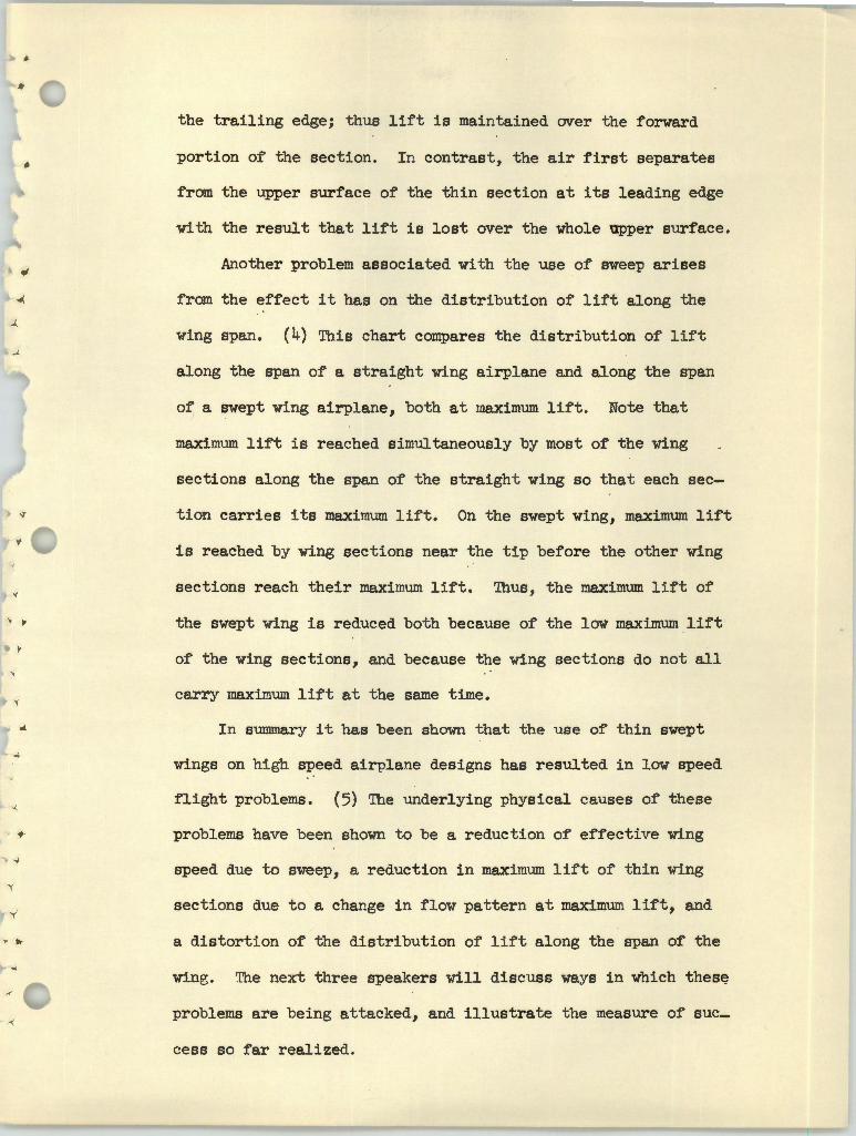
• the trailing edge; thus lift is maintained over the forward
portion of the section. In contrast, the air first separates
from the upper surface of the thin section at its leading edge
with the result that lift is lost over the whole upper surface.
Another problem associated with the use of sweep arises
from the effect it has on the distribution of lift along the
wing span. (4) This chart compares the distribution of lift
along the span of a straight wing airplane and along the span
of a swept wing airplane, bot h at maximum lift. Note that
maximum lift is reached simultaneously by most of the wing
sections along the span of the straight wing so that each sec
tion carries its maximum lift. On the swept wing, maximum lift
is reached by wing sections near the tip before the other wing
sections reach their maximum lift. Thus, the maximum l i ft of
the swept wing is reduced both because of the low maximum lift
of the wing sections, and because the wing sections do not all
carry maximum lift at the same time.
In summary it has been shown that the use of thin swept
wings on high speed airplane designs has resulted in low speed
flight problems. (5) The underlying physical causes of these
problems have been shown to be a reduction of effective wing
speed due to sweep, a reduction in maximum lift of thin wing
sections due to a change in flow pat tern at maximum lift, and
a distortion of the distribution of lift along the span of the
wing. 'l'he next three speakers will discuss ways in which thes~
problems are being attacked, and illustrate the measure of sue_
cess so far realized.
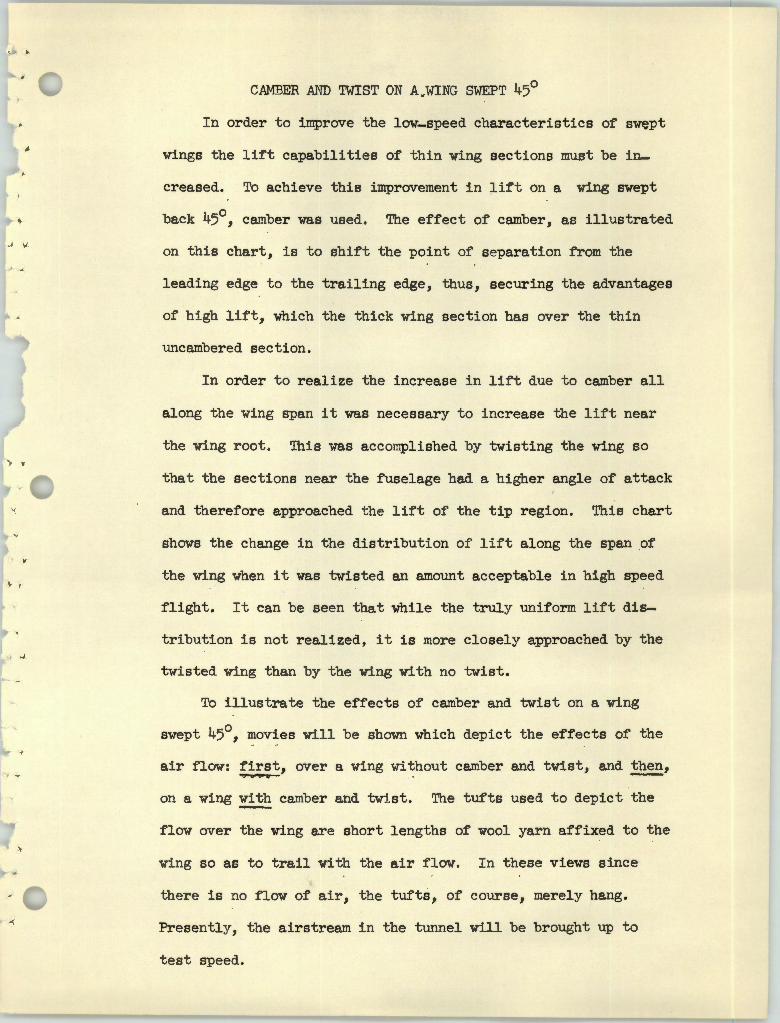
CAMBER AI'ID TWIST ON A.WING SWEPT 45°
In order to improve the low-speed characteristics of swept
wings the lift capabilities of thin wing sections must be in
creased. To achieve this improvement in lift on a wing swept
back 45°, camber was used. The effect of camber, as illustrated
' "' on this chart, is to shift the point of separation from the
leading edge to the trailing edge, thus, securing the advantages
of high lift, which the thick wing section has over the thin
uncambered section.
In order to realize the increase in lift due to camber all
along the wing span it was necessary to increase the lift near
the wing root. This was accomplished by twisting the wing so
that the sections near the fuselage had a higher angle of attack
and therefore approached the lift of the tip region. This chart
shows the change in the distribution of lift along the span of . .
the wing when it was twisted an amount acceptable in high speed
flight. It can be seen that while the truly uniform lift dis
tribution is not realized, it is more closely approached by the
twisted wing than by the wing with no twist.
To illustrate the effects of camber and twist on a wing
swept 45°, movies will be shown which depict the effects of the
air flow: first, over a wing without camber and twist, and ~' ..,..._.._
on a wing ~ camber and twtst. The tufts used to depict the
flow over the wing are short lengths of wool yarn affixed to the
wing so as to trail with the air flow. In these views since
there is no flow of air, the tufts, of course, merely hang.
Presently, the airstream in the tunnel will be brought up to
test speed.
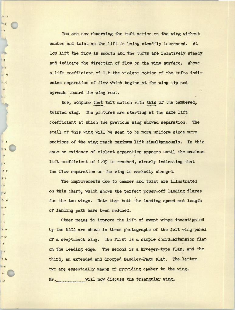
You are now observing the tuft action on the wing without
camber and twist as the lift is being steadily increased. At
low lift the flow is smooth and the tufts are relatively steady
and indicate the direction of flow on the wing surface. Above .
a lift coefficient of 0. 6 the violent motion of the tufts indi
cates separation of flow which begins at the wing tip and
spreads toward the wing root.
Now, compare ~ tuft action with this of the cambered,
twisted wing. The pictures are starting at the same lift
coefficient at which the previous wing showed separation. The
stall of this wing will be seen to be mar~ uniform since more
sections of the wing reach maximum lift simultaneously. In this
case no evidence of violent separation appears until the maxim.um
lift coefficient of 1.09 is reached, clearly indicating that
the flow separation on the wing is markedly changed • .. .
The improvements due to camber and twist are illustrated
on this chart, which shows the perfect power-0ff landing flares
for the two wings. Note that both the landing speed and length
of landing path have been reduced.
Other means to improve the lift of swept wings investigated
by the NACA are shown in these photographs of the left wing panel .. ,
of a swept-back wing. The first is a simple chord-extension flap
on the leading edge. The second is a Krueger-type flap, and the
.. .. third, an extended and drooped Handley-Page slat. The latter
two are essentially means of providing camber to the wing.
Mr.------will now discuss the triangular wing.
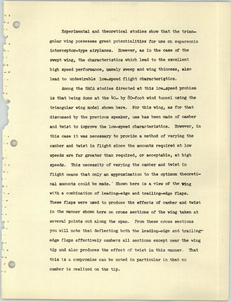
Experimental and theoretical studies show that the trian
gular wing possesses great potentialities for use on supersonic
interceptor-type airplanes. However, as in the case of the
swept wing, the characteristics which lead to the excellent
h:i.gh speed performance, namely sweep and wing thinness, also- " lead to undesirable low-speed flight characteri~tics.
Among the NACA studies directed at this low-speed problem
is that being done at the 40- by 80-foot wind tunnel using the
triangular wing model shown here. For this wing, as for that
discussed by the previous speaker, use has been made of camber
and twist to improve the low-speed characteristics. However, in
this case it was necessary to provide a method of varying the
camber and twist in flight since the amounts required at low
speeds are far greater than required, or acceptable, at high
. ' speeds. This necessity of varying the camber and twist in
flight means that only an approximation to the optimum theoreti
cal amounts could be made. · Shown here is a view of the Wing
with a combination of leading-edge and trailing-edge flaps.
These flaps were used to ~roduce the effects of camber and twist
in the manner shown here on cross sections of the wing taken at
several points out along the span. From these cross sections
you wUl note that deflecting both the leading-edge and trail i ng-
edge flaps effectively c2Jnbers all sections except near the ·wing
tip and also produces the effect of t wist in this manner . That
this i s a compromise can be noted in particular in that no
camber is r ealized on the tip.
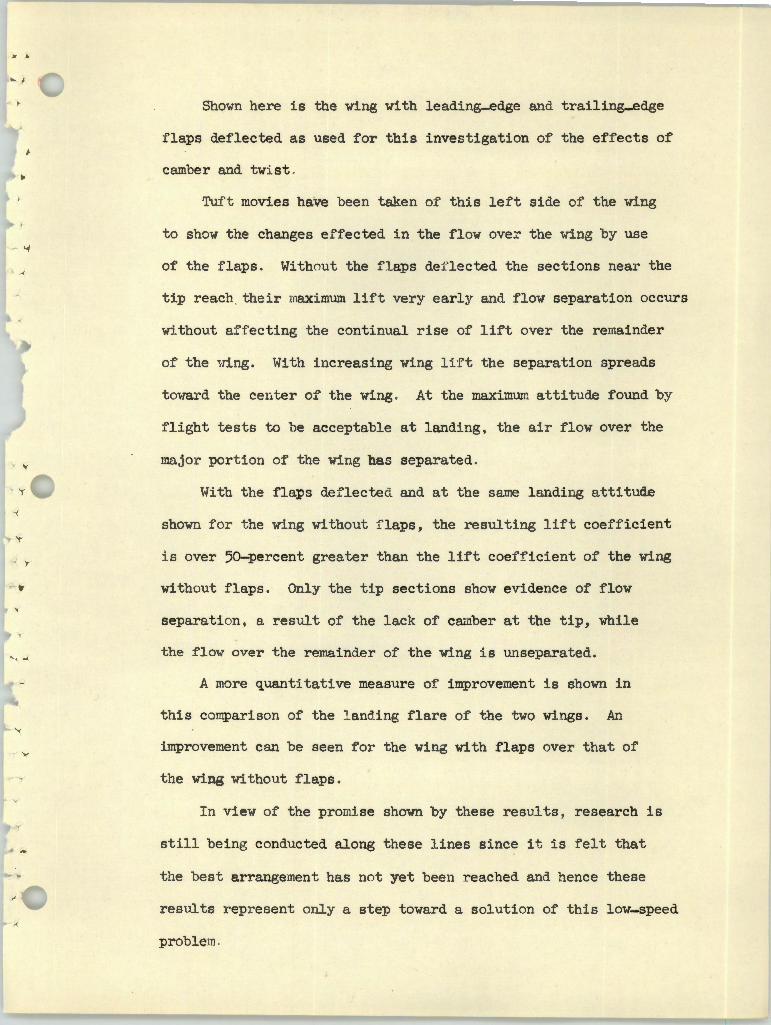
Shown here is the wing with leading-edge and trailing_edge
flaps deflected as used for this investigation of the effects of
camber and twist ... Tuf t movies have been taken of this le:ft side of the wing
to show the changes effected in the flow over the wing by use - _,
of the flaps. Without the flaps def lected the sections near the
tip reach . their maximum lift very early and flow separation occurs
w:i_thout affecting the continual rise of lift over the remainder
of the ~-ring. With increasing wing lift the separation spreads
t oward the center of the wing . At the maximure attitude found by
flight tests to l)e acceptable at lanMng, the air flow over the
ma,jor portion of the wing has separated .
With the flaps deflected and at the same landing attitude
shown for the wing without f laps, the resulting lift coefficient
i s over 50-percent greater than the lift coefficient of the wing
without flaps. Only the tip sections show evidence of flow
separation, a result of the lack of ca;nber at the tip, while
' _, the flow mrer the remainder of the wing is unsepa.rated.
A more quantitative measure of improvement is shown in
this comparison of the l anding flare of the two wings. An
improvement can be seen for the wing with flaps over that of
the wing without flaps.
I n view of the promise shown by these results, research is
still being conducted along these lines since it is felt that
the best arrangement has not yet been reached and hence these
results r epr esent only a step toward a solution of this low-speed
problem.
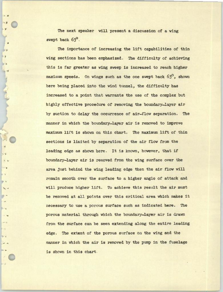
• The next speaker will present a discussion of a wing
swept back 63° .
The importance of increasing the lift capabilities of thin
wing sections has been emphasized . The di fficulty of achieving
this is far greater as wing sweep is increased to reach higher
maximum speeds. On wings such as the one swept back 63°, shown
here being placed into the wind tunnel, the difficulty has
in.creased to a point t hat warrants the use of the complex but
M.ghly effective procedure of removing the bounda:ry..J.ayer air
by suction to delay the occurrence of air-f low separation. The
manner in which the boundary-layer air is removed to improve
maximum lif t is shown on this chart . The maximum lift of thin
secti ons is limited by separat ion of the air flow from the
leading edge as shmm here . It is known, however, that if
boundar y-layer air is removed from the wing surface over the
- . area just behind the wing leading edge then the air flow will
r emain smooth over the surface to a higher angle of attack and
will produce higher l i f t . To achieve this result the air must
be removed at all points over this critical area which makes it
necessar y t o use a por ous surface such as indicat ed here. The
por ous material through which the boundary-layer a i r is drawn
f rom the surface can be seen extending along the entire leading
edge. The extent of the porous sur f ace on the wing and the
manner i n which the air is removed by the pump in the fuselage
i s shown in this chart
.. "
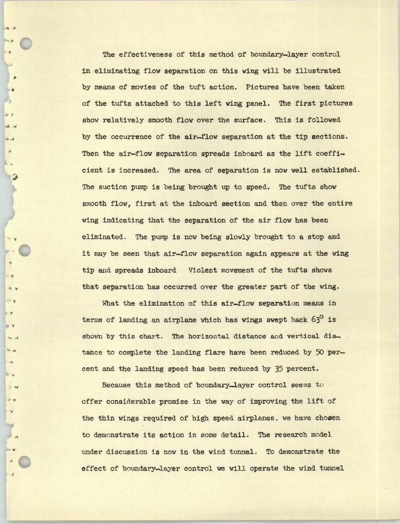
The effectiveness of this method of boundary-layer control
in eliminating flow separation on this wing will be illustrated
by means of movies of the tuft action. Pictures have been taken
of the tufts attached to this left wing panel. The first pictures
show relatively smooth flow over the surface. This is followed
by the occurrence of the air-flow separat ion at the tip sections.-" Then the air-flow separation spreads inboard as the lift coeffi
cient is increased. The area of separation is now well established.
The suction pump is being brought up to speed.. The tufts show
smooth flow, first at the inboard section and then over the entire
wing indicating that the separation of the air flow has been
eliminated. The pump is now being slowly brought to a stop and
it may be seen that air-flow separation again appears at the wing
tip and spreads inboard Vj_olent movement of the tufts shows
that separation has occurred over the greater part of the wing.
What the elimination of this air-flow separation means in
ter~ns of landing an airplane which has wings swept back 63° is
shovm by this chart . The horizontal distance a nd vertical dis
-..\ tance t o complete the l anding flare have been reduced by 50 per
cent and the landing speed has been reduced by 35 percent.
Because this method of boundary-layer control seems t o
of fer considerable promise i n t he way of improving the lift of
the thin wings required of high speed airplanes. we have chosen
to demonstrate tts action in some detail. The research model
under discussion i s now in the wind ttmnel. To demonstrate the
effect of boundar y-layer control we will operate the wind tunnel
I ,
t '
, •r
' )
' .
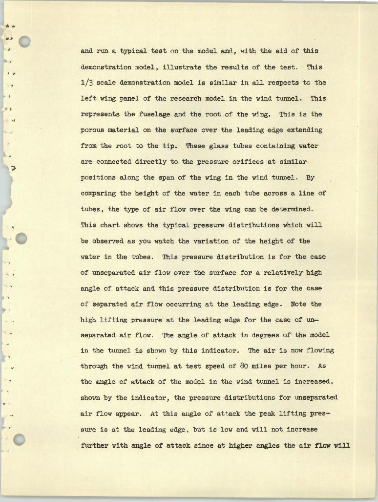
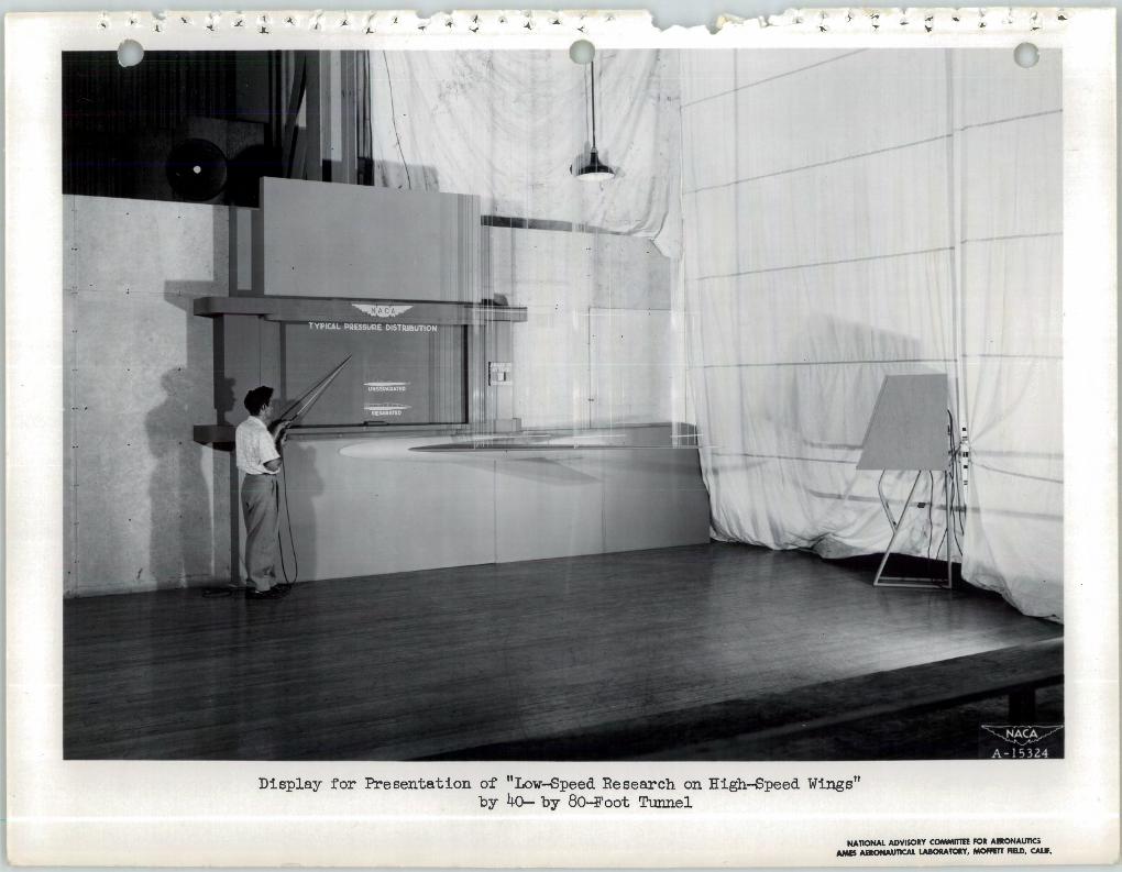
and nm a typical test on the model and, with the aid of this
demonstration model. illustrate the results of the test. This
1/3 scale demonstration model is similar in all respects to the
left wing :panel of the research model in the wind tunnel. This
represents the fuselage and the root of the w1.ng. This is the
porous material on the surface over the leading edge extending
from the root to the tip. These glass tubes contatning water
are connected directly to the pressure orifices at similar
positions along the span of the wing in the wj_nd. tunnel. By
comparing the height of the water in each tube across a line of
tubes, the type of air flow over the wing can be determined.
This chart shows the typical pressure distributions which will
be observed a.s you watch the variation of the height of the
water in the tubes. This pressure distribution is for the case
of u_~separated air flow over the surface for a relatively high
angle of attack and this pressure distribution is for the case
of separated air flow occurring at the leading edge. Note the
high lift ing pressure at the leading edge for the case of un
separated air flow. The angle of attack in degrees of the model
in the tunnel is shown by this indicator. The air is now flowing
through the wind tunnel at test speed of 80 miles per hour. As
the angle of attack of the model in the wind tunnel is increased,
shmm by the indicator, the pressure distributions for unseparated
air flow appear. At this angle o-? att ack the peak lifting pres
sure is at the leading edge , but is low and will not increase
further with angle of attack since at higher angles the air flow will
•
< ..
- '
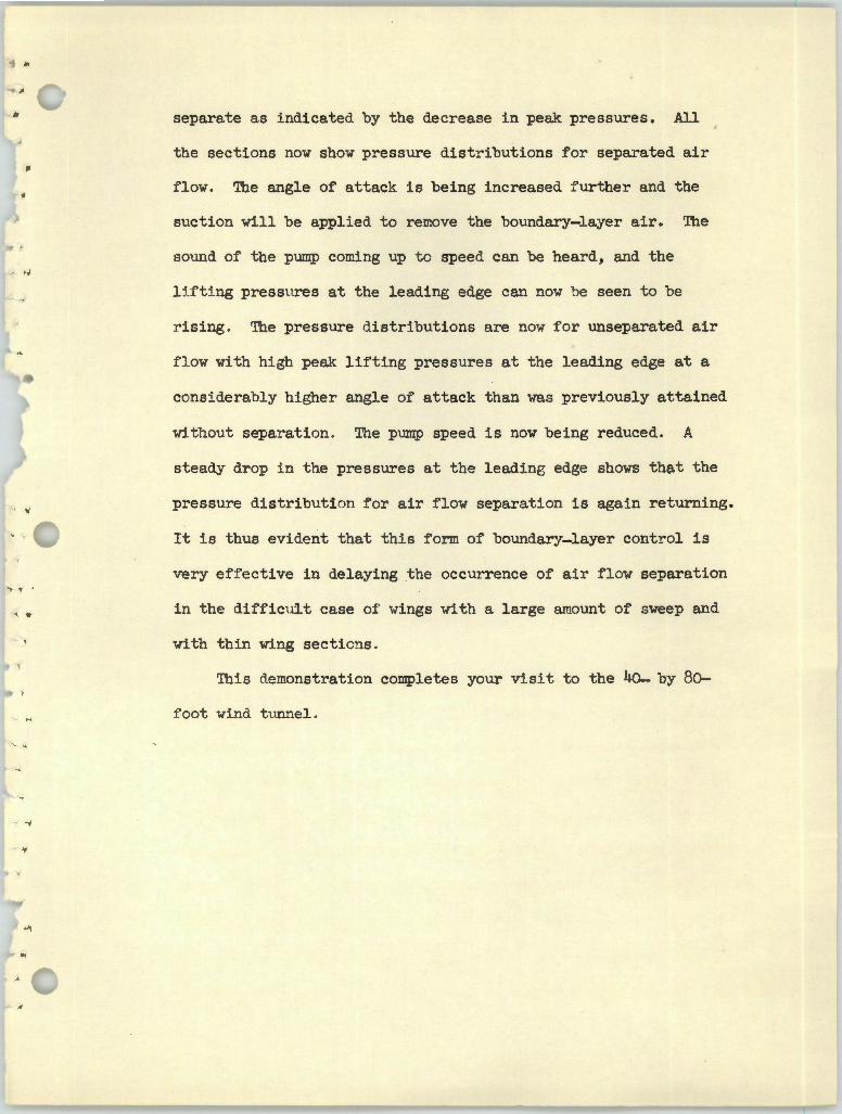
separate as indicated by the decrease in peak pressures. All
the sections now show pressure distributions for separated air
flow. The angle of attack is being increased further and the
suction will be applied to remove the boundary-layer air. The
sound of the pump coming up to speed can be heard., and the
l H t i ng pressures at the leading edge can now be seen to be
r ising . The pressure distributions are now for unseparated air
f low with hi gh peak lifting pressures at the leading edge at a
considerably higher angle of attack than was previously attained
without separation . The pu.mp speed is now being reduced. A
steady drop in the pressures at the leading edge shows that the
pressure distribution for air flow separation is again returning.
It is thus evident that this form of boundary-layer control is
very effective in delaying the occurrence of air flow separation
in the difficult case of wings with a large amount of sweep and
with thin wing sections .
This demonstration completes your visit to the 40- by 80
f oot wind tlmnel.
.J ..'.L ._, ~ A .L ._"' _._ L
,. < .._
;., .., ~ ~ "'
Display for Presentation of "Low-Speed Research on High-Speed Wings" by 40- by 80-Foot Tunnel
NATIONAL ADVISORY COMMITTEE FOR AERONAUTIG AMIS AERONAUTICAL LABORATORY, MOffETT FIRD, CALIF.