
low Passband Sensitivity Digital Filters: A Generalized...
20
low Passband Sensitivity Digital Filters: A Generalized Viewpoint and Synthesis Procedures P. P. VAIDYANATHAN, MEMBER, IEEE, AND SANJIT K. MITRA, FELLOW, IEEE The concepts of losslessness and maximum available power are basic to the lowsensitivityproperties of doubly terminated lossless networksofthecontinuous-timedomain. Based on similar con- cepts, we develop a new theory for lowsensitivity discrete-time filter structures. The mathematical setup for the development is the bounded-real property of transfer functions and matrices. Starting from this property, we derive procedures for the synthesis of any stable digital filter transfer function by means of a lowsensitivity structure. Most of the structures generated by this approach are interconnections of a basic building block called digital “two-pair,” and each two-pair is characterized by a lossless bounded-real (1BR) transfer matrix. The theory and synthesis procedures also cover special cases such as wave digital filters, which are derived from continuous-time networks, and digital lattice structures, which are closely related to unit elements of distributed network theory. 1. INTRODUCTION In practice, a digital filter implemented either on a gen- eral-purpose computer or by using special-purpose hard- ware behaves differently from its idealizeddesigndue to the finite word-length available to represent the signal variables and the multiplier coefficients. One of the practi- cal issues, among others, is thus the sensitivity of filter performance to minor variations ofthemultipliercoeffi- cients. The importance of low-sensitivity structures arises out of thefactthat the characteristics of such a structure implementated with quantized multiplier coefficients is very close to that of an ideal infinite-precision implementation. In addition, if the multiplier coefficients can be represented by fewer bits, the implementation could operate at a faster speed and/or be less expensive. Moreover, there exist cer- tain structures in which, if themultipliercoefficients are restricted to a certainrangethestructures are necessarily stable. Thus for such structures, parameter quantization can be done in such a way that stability is not impaired. A. Background Classical, doubly terminated lossless networksdesigned in the continuous-time domain to meet maximum-avail- Manuscript received July 15, 1983; revised January 24, 1984. This work was supported by the National Science Foundation under Grant ECS 82-18310. P. P. Vaidyanathan is with the Department of Electrical Engineer- ing, California Institute of Technology, Pasadena, CA 91125, USA. 5. K. Mitra is with the Department of Electrical and Computer Engineering, University of California, Santa Barbara, CA 93106, USA. able-power bounds, are known to have low passband sensi- tivity, as explained by Orchard [I]. Wave digital filters, originally proposed by Fettweis [2], are a family of filter structures derived by imitating classical doubly terminated lossless electrical networks. It was originally conjectured that these structures will inherit the low-sensitivity proper- ties of the continuous-time structures. Crochiere [3] demon- strated this conjecture for a number of design examples in 1972. A typical wave digital filter design starts with a proto- type LC network, and each circuit element is transformed into an equivalent element.in the signal flow network. This transformation is done by viewing each element as a one- port. During this imitation process, a transformation of the voltageandcurrentvariables is made, so that the signals appearing in the digital signal flowgraph are not discretized versions of voltage and current, but linear combinations thereof, called the incident and reflected waves. The reason for making the transformation is that, if voltage and current are retained as variables of the flowgraph, certain delay-free loops appear, making the structure “unrealizable.” How- ever, if “waves” are used as variables in the flowgraph, this can usually be avoided by following certain elegant inter- connection rules [2]. According to the work in [2], it appears that the low-sensitivity properties are the result of an imita- tion of low-sensitivity continuous-time filters, and the use of wave variables themselves has only to do withrealizabil- ity considerations. To interconnect wave-ports of different characteristic impedances, ”wave adaptors” are used, which are basically multiport interconnection networks, having no internal delay elements. Fettweis and others, in more recent work, show that, wave filters have other desirable properties, such as internal stability and immunity from granular oscillations [4], [5]. Swamy and Thyagarajan [6] in 1975 and Constantinides [7] in 1976 showed that special types of digital filter cascade structurescanbe obtained from classical continuous-time networks by considering each element in the continuous- time domain as a two-port rather than a one-port (as originally done by Fettweis). In the resulting structures, adaptors do not make an explicit appearance. These struc- tures were demonstrated to have low-sensitivity properties similar to wave filters. In 1978 Lawson [8] showed how the voltage-current to wave transformation can be generalized, and in 1980 Ali 191 extended this idea to obtain more structures having low-sensitivity properties. Cascaded digital ladder and lattice structures (the “Gray CQ18-9219/&1/o4oo-0404$01 .oO q9W IEEE PROCEEDINGS OF THE IEEE. VOL. 72, NO 4, APRIL 1984
Transcript of low Passband Sensitivity Digital Filters: A Generalized...
low Passband Sensitivity Digital Filters: A Generalized Viewpoint and Synthesis Procedures
P. P. VAIDYANATHAN, MEMBER, IEEE, AND SANJIT K . MITRA, FELLOW, IEEE
The concepts of losslessness and maximum available power are basic to the lowsensitivity properties of doubly terminated lossless networks of the continuous-time domain. Based on similar con- cepts, we develop a new theory for lowsensitivity discrete-time filter structures. The mathematical setup for the development is the bounded-real property of transfer functions and matrices. Starting from this property, we derive procedures for the synthesis of any stable digital filter transfer function by means of a lowsensitivity structure. Most of the structures generated by this approach are interconnections of a basic building block called digital “two-pair,” and each two-pair is characterized by a lossless bounded-real (1BR) transfer matrix.
The theory and synthesis procedures also cover special cases such as wave digital filters, which are derived from continuous-time networks, and digital lattice structures, which are closely related to unit elements of distributed network theory.
1 . INTRODUCTION
In practice, a digital filter implemented either on a gen- eral-purpose computer or by using special-purpose hard- ware behaves differently from its idealized design due to the finite word-length available to represent the signal variables and the multiplier coefficients. One of the practi- cal issues, among others, is thus the sensitivity of filter performance to minor variations of the multiplier coeffi- cients. The importance of low-sensitivity structures arises out of the fact that the characteristics of such a structure implementated with quantized multiplier coefficients is very close to that of an ideal infinite-precision implementation. In addition, i f the multiplier coefficients can be represented by fewer bits, the implementation could operate at a faster speed and/or be less expensive. Moreover, there exist cer- tain structures in which, if the multiplier coefficients are restricted to a certain range the structures are necessarily stable. Thus for such structures, parameter quantization can be done in such a way that stability is not impaired.
A. Background
Classical, doubly terminated lossless networks designed in the continuous-time domain to meet maximum-avail-
Manuscript received July 15, 1983; revised January 24, 1984. This work was supported by the National Science Foundation under Grant ECS 82-18310.
P. P. Vaidyanathan is with the Department of Electrical Engineer- ing, California Institute of Technology, Pasadena, CA 91125, USA.
5. K . Mitra i s with the Department of Electrical and Computer Engineering, University of California, Santa Barbara, CA 93106, USA.
able-power bounds, are known to have low passband sensi- tivity, as explained by Orchard [I]. Wave digital filters, originally proposed by Fettweis [2], are a family of filter structures derived by imitating classical doubly terminated lossless electrical networks. It was originally conjectured that these structures will inherit the low-sensitivity proper- ties of the continuous-time structures. Crochiere [3] demon- strated this conjecture for a number of design examples in 1972. A typical wave digital filter design starts with a proto- type LC network, and each circuit element is transformed into an equivalent element.in the signal flow network. This transformation is done by viewing each element as a one- port. During this imitation process, a transformation of the voltage and current variables is made, so that the signals appearing in the digital signal flowgraph are not discretized versions of voltage and current, but linear combinations thereof, called the incident and reflected waves. The reason for making the transformation is that, if voltage and current are retained as variables of the flowgraph, certain delay-free loops appear, making the structure “unrealizable.” How- ever, if “waves” are used as variables in the flowgraph, this can usually be avoided by following certain elegant inter- connection rules [2]. According to the work in [2], it appears that the low-sensitivity properties are the result of an imita- tion of low-sensitivity continuous-time filters, and the use of wave variables themselves has only to do with realizabil- ity considerations. To interconnect wave-ports of different characteristic impedances, ”wave adaptors” are used, which are basically multiport interconnection networks, having no internal delay elements.
Fettweis and others, in more recent work, show that, wave filters have other desirable properties, such as internal stability and immunity from granular oscillations [4], [5].
Swamy and Thyagarajan [6] in 1975 and Constantinides [7] in 1976 showed that special types of digital filter cascade structures can be obtained from classical continuous-time networks by considering each element in the continuous- time domain as a two-port rather than a one-port (as originally done by Fettweis). In the resulting structures, adaptors do not make an explicit appearance. These struc- tures were demonstrated to have low-sensitivity properties similar to wave filters. In 1978 Lawson [8] showed how the voltage-current to wave transformation can be generalized, and in 1980 Ali 191 extended this idea to obtain more structures having low-sensitivity properties.
Cascaded digital ladder and lattice structures (the “Gray
CQ18-9219/&1/o4oo-0404$01 .oO q9W I E E E
PROCEEDINGS OF THE IEEE. VOL. 72, NO 4, APRIL 1984
and Markel” structures [Ion, are not derived from continu- and cascaded-lattice structure building blocks fall under the ous-time lumped filters, but share some properties in com- class of structures advanced here. mon with wave filters, such as passivity and freedom from granular oscillations [Ill, [12]. II. PRELIMINARIES
8. Objective and Outline
Our aim in this paper is to develop a general framework for the design of digital filter structures exhibiting low sensitivity of the magnitude response in the passband with respect to the multiplier coefficients. We restrict ourselves to linear time-invariant, causal, one-dimensional digital filters. The proposed theoretical framework not only leads to well-known low-sensitivity structures such as wave dig- ital filters [2] and cascaded-lattice structures [IO], but also forms the basis of a number of new such structures. We thus expand the family of filter structures that have favor- able coefficient quantization properties. The new theory developed entirely in the z-domain, is based on the con- cept of ”losslessness” of certain building blocks. All the developments and results reported here are independently developed for discrete-time systems, without any reference to continuous-time-domain counterparts. (Occasional refer- ence to continuous-time domain is made whenever it be- comes instructive to point out certain similarities and analo- gies with existing classical filter theory results.) An obvious advantage of such generality and independence from refer- ence to continuous-time filters is the following: There are several important design methods advanced by Dolan and Kaiser [13], Deczky [14], Saramaki [15], Rabiner [16], and others that develop directly in the z-domain, digital transfer functions with optimal magnitude characteristics. Using our new theory, low-sensitivity structures that share many of the attractive properties of wave digital filters can also be derived for these transfer functions, even though they do not have their origin in the continuous-time domain, and as a result, cannot be implemented with wave digital filter Structures.
We first review some basic concepts, definitions and notations in Section It. In Section Ill, we start from a z-domain description of a digital filter and arrive at the conditions for low sensitivity of structures. We show that, in a natural way this gives rise to the concept of bounded- real (BR) and lossless bounded-real (LBR) functions and structures. In Section IV we look into some general proper- ties of LBR-based structures. For the digital LBR two-pair we provide an extensive list of properties in terms of the chain parameters [17]. We derive general conditions that a digital two-pair must satisfy in order to be a basic first-order LBR two-pair. We then consider interconnection properties of LBR two-pairs. At the beginning of Section V we look into other “LBR-like” structures, which are sufficient for low- sensitivity designs. This section is on the synthesis of a scalar lossless bounded-real function using “LBR extraction approach” and lays the basic mathematical foundation for the succeeding sections. In Section VI, we outline the synthesis of general BR functions. First- and second-order LBR building blocks that lead to realizable cascaded struc- tures are developed here. The resulting structures have very-low passband sensitivity, and we include a number of synthesis examples in Section VI1 to demonstrate this point. Finally, in Section Vlll we show how the wave digital filters,
In this paper, lower case letters denote constants. Lower case letters with an argument (such as h(n), g(rn), f ( k ) , etc.) denote scalar functions of discrete-time index. Upper case letters indicate scalar functions, with the independent variable being a transform variable, for example H(eiU), G(z), etc. Wherever functional dependence is obvious, we may not explicitly indicate it.
Upper case script letters denote a vector or a matrix, for example F(z), Y(z), etc. Superscript asterisk stands for transposed conjugate and superscript tilde is used to indi- cate a transposition followed by replacement of the inde- pendent variable by its reciprocal. Thus, H*(z) = H(z*), .T*(z) = F ( Z * ) , i ( z ) = ~ ( z - ’ ) , 4 ( z ) = ~ ‘ ( z - ’ ) for scalar and matrix transfer functions, respectively. On the unit circle of the z-plane, “ - ’ I and “*” clearly are equivalent.
Next, given a scalar transfer function C(z), we denote its first and second derivatives with respect to z-’ as G‘(z) and C”(z), respectively. Upper-case f stands for the identity matrix whose order can be understood from the context, and 8 stands for null matrix of appropriate dimensions. The notation 9 < 1 where 9 and 2 are square matrices, is an abbreviation for ”2 - 9” being positive semidefinite. Thus 9* (z )9(z ) < Y implies, [ 9 (z )Y ] *9 (z )Y< Y * 9 for all (complex) vectors Y.
X ( Z l -+--Y(c)
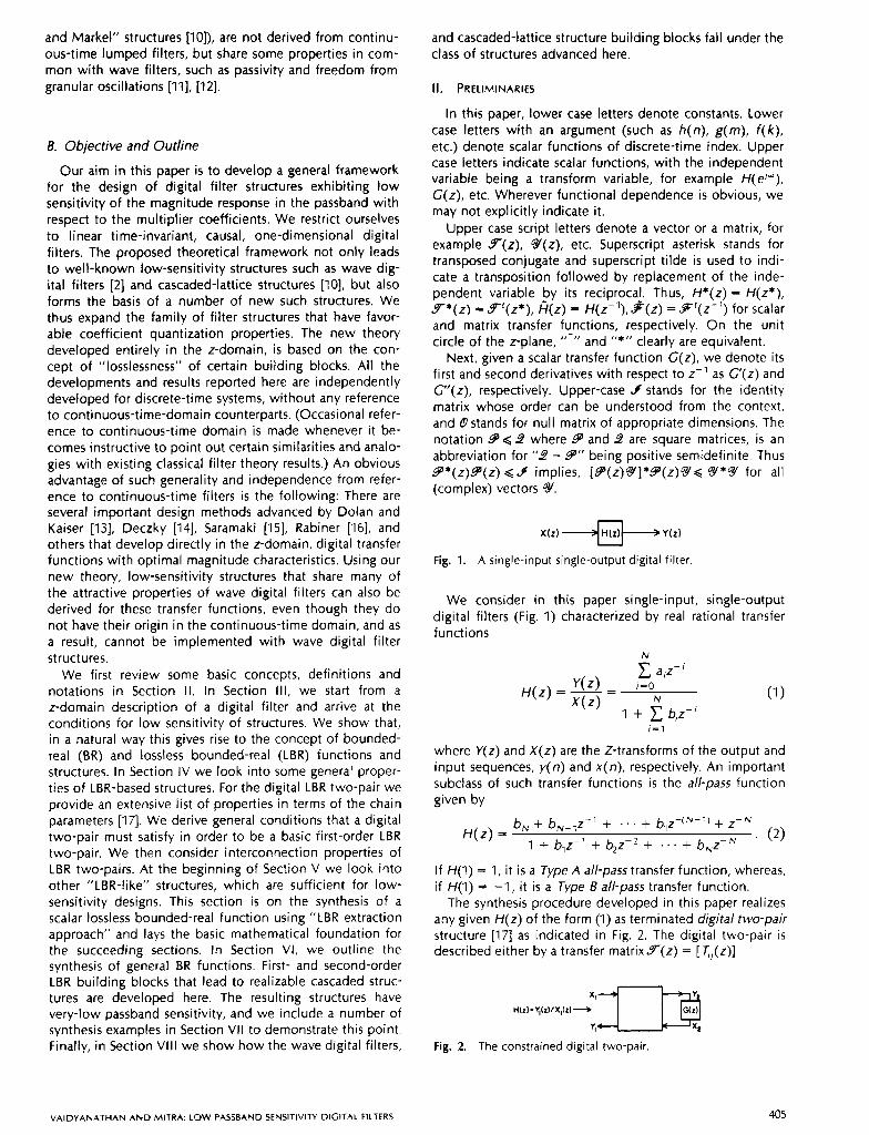
Fig. 1. A single-input single-output digital filter
We consider in this paper single-input, single-output digital filters (Fig. 1) characterized by real rational transfer functions
N
ajz-’ Y(z) i-0 H(z) = - = N (1 1 x(z) 1 + biz-(
i-I
where Y(z) and X(z) are the Z-transforms of the output and input sequences, y(n) and x(n) , respectively. An important subclass of such transfer functions is the all-pass function given by
H ( z ) = b, + b,-,z-l + . . . + b,z-(N-” + Z-N
1 + b,z-l + 42-2 + . . . + b,z-N (2)
If H(1) = 1, it is a Type A all-pass transfer function, whereas, if H(1) = -1, it is a Type 8 all-pass transfer function.
The synthesis procedure developed in this paper realizes any given H(z) of the form (1) as terminated digital two-pair structure [I71 as indicated in Fig. 2. The digital two-pair is described either by a transfer matrixY(z) = [ T,,(z)]
Fig. 2. The constrained digital two-pair.
VAIDYANATHAN A N D MITRA: LOW PASSBAND SENSITIVITY DIGITAL FILTERS
now the multiplier coefficient m, is perturbed Y ( z ) = mi -+ m, + Am, (9)
= Y ( Z ) % ( Z ) (3)
or equivalently by a chain matrix I I ( z )
The elements of above two-pair matrices are related through
The input transfer function H(z) of the constrained two- pair of Fig. 2 can be expressed in terms of the two-pair parameters and the constraining transfer function C ( z ) as
or equivalently, the constraining transfer function C ( z ) can be expressed in terms of the input transfer function H(z) by
A two-pair is said to be reciprocal if T,, = T2, or AD - BC = 1 [18]. Likewise, a two-pair is anti-reciprocal if T,, = - T,, or AD - BC= -1.
111. REQUIREMENTS FOR LOW SENSITIVITY OF DIGITAL FILTER STRUCTURES
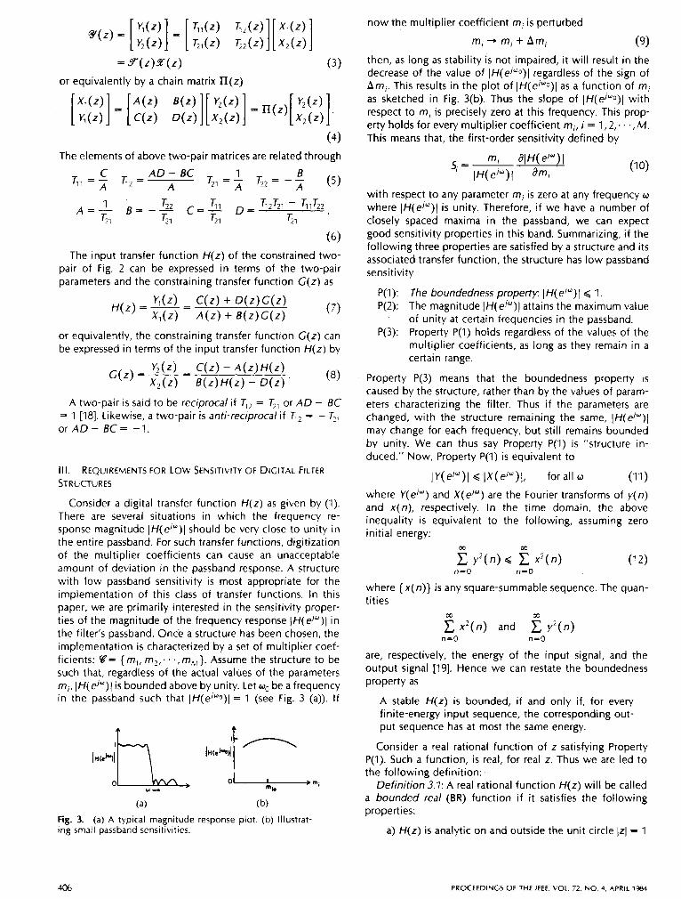
Consider a digital transfer function H(z ) as given by (1). There are several situations in which the frequency re- sponse magnitude IH(e/")l should be very close to unity in the entire passband. For such transfer functions, digitization of the multiplier coefficients can cause an unacceptable amount of deviation in the passband response. A structure with low passband sensitivity is most appropriate for the implementation of this class of transfer functions. In this paper, we are primarily interested in the sensitivity proper- ties of the magnitude of the frequency response IH(e'")l in the filter's passband. Once a structure has been chosen, the implementation is characterized by a set of multiplier coef- ficients: Q= { m,, m2; * . ,mh,}. Assume the structure to be such that, regardless of the actual values of the parameters m,, IH(e'")l is bounded above by unity. Let w,, be a frequency in the passband such that IH(e/"o)>l = 1 (see Fig. 3 (a)). If
4 f
Fig. 3. (a) A typical magnitude response plot. (b) Illustrat- ing small passband sensitivities.
then, as long as stability is not impaired, it will result in the decrease of the value of IH(ej"o)[ regardless of the sign of Am;. This results in the plot of IH(ej"o)>l as a function of m, as sketched in Fig. 3(b). Thus the slope of 1H(ej"o)>l with respect to m, is precisely zero at this frequency. This prop- erty holds for every multiplier coefficient m,, i = 1,2;. . ,M. This means that, the first-order sensitivity defined by
with respect to any parameter m, is zero at any frequency w where IH(e'")l is unity. Therefore, if we have a number of closely spaced maxima in the passband, we can expect good sensitivity properties in this band. Summarizing, if the following three properties are satisfied by a structure and its associated transfer function, the structure has low passband sensitivity
P(1): The boundedness property: IH( e'")l < 1. P(2): The magnitude IH(e'")l attains the maximum value
of unity at certain frequencies in the passband. P(3): Property P(1) holds regardless of the values of the
multiplier coefficients, as long as they remain in a certain range.
Property P(3) means that the boundedness property is caused by the structure, rather than by the values of param- eters characterizing the filter. Thus if the parameters are changed, with the structure remaining the same, IH(e/")l may change for each frequency, but still remains bounded by unity. We can thus say Property P(1) is "structure in- duced." Now, Property P(1) is equivalent to
IY(el")l Q Ix (e/ " ) l , for all w (11)
where Y( e'"') and X ( e'") are the Fourier transforms of y( n) and ~ ( n ) , respectively. In the time domain, the above inequality is equivalent to the following, assuming zero initial energy:
n=O n-0
where { x ( n) } i s any square-summable sequence. The quan- tities
c x 2 ( n ) and c v ' (n ) 00 ffi
n=O n-0
are, respectively, the energy of the input signal, and the output signal [19]. Hence we can restate the boundedness property as
A stable H(z) i s bounded, if and only if, for every finite-energy input sequence, the corresponding out- put sequence has at most the same energy.
Consider a real rational function of z satisfying Property P(1). Such a function, is real, for real z. Thus we are led to the following definition:
Definition 3.1: A real rational function H(z) will be called a bounded real (BR) function if i t satisfies the following properties:
a) H(z) is analytic on and outside the unit circle IzI = 1
406 PROCEEDINGS OF THE IEEE. VOL 72, NO 4. APRIL 1984
b) IH(e/")l G 1, for all w .
It can be shown, with the help of the maximum modulus theorem, that if H(z) is BR then IH(z)l < 1 for (zI > 1 unless H(z) is a constant. Note that Condition a) is equivalent to stability, whereas, Condition b) can always be satisfied by scaling. Clearly, these do not, by themselves imply low sensitivity, which is a property related to the structure. It is Property P(3) that i s crucial for low sensitivity. Accordingly, we turn our attention to this issue.
9 (z)Y(z) = 4, for all z (1 7)
and
Y * ( z ) Y ( r ) ~ 4 , fo r l z l2 I . (1 8)
In summary, given a scalar BR transfer function H(z), we can realize it by a low-sensitivity structure if we can find a means of "embedding" it into a 2 x 2 transfer matrix satis- fying (1 7 ) .
The inequality (18) implies
S * Y * ( z ) S ( z ) S < S*Y, for all 9. (19)
Note that (16) implies that for an LBR two-pair A. Choice of the Basic Structure
We are looking for structures that impose certain boundedness conditions on the transfer function, regardless of the values of the parameter vector (as long as stability i s not violated). Let us first look at the easier problem where the inequality in (11) is a strict equality. This corresponds to an all-pass transfer function as given by (2). Because of equality in (11) and (12), the transfer function of (2) will be called a lossless bounded-real (LBR) function. Since the numerator polynomial is the mirror image of the denomina- tor polynomial, there are only N distinct coefficients in- volved. It is possible, therefore, to obtain structures with, N multipliers of values'b, [20]. Thus if a particular multiplier coefficient b, changes to b, + Abip the mirror image relation between numerator and denominator is still retained, and therefore (11) continues to hold with equality. As long as the perturbations do not cause any pole to move outside the unit circle, the all-pass filter will remain stable. Thus for LBR functions, the constraint on the coefficients makes it possible to induce Property P(1) structurally.
If the transfer function is not LBR, the above situation does not hold, and we should find other means of inducing Property P(1) through structure. For this, note that the key property of an all-pass filter is the equality, H(z-~)H(z) = 1. It can be shown (as we shall see later) that if F ( z ) is the transfer matrix of a digital two-pair then the following property:
P ( z - l ) F ( z ) = 4, for all z (13) can be "structure-induced" in a way similar to the case of an all-pass filter. The condition of (13), which we call para-unitariness, implies
IT,k(e'")(' + IT2k(ei")12 = 1 , k = 1,2 (14)
on the unit circle. Thus each one of the scalar transfer functions T,,(z) is bounded as
I Ti( e'")l G 1, for all o. (1 5)
Thus we can induce the boundedness property by means of a two-pair exhibiting the "matrix all-pass property" (see (13)). With this motivation, we define now the lossless bounded-realness of a digital two-pair as follows:
Definition 3.2: A digital two-pair, described by the transfer matrixF(z) (with real coefficients) is called lossless bounded-real if
a) Each element of Y ( z ) is stable, b) F*(e'")F(e'") = 4, for all o in 0 w < 2rr.
(1 6) Condition a) implies analyticity in (zI 3 1. It can thus be shown that i f Y(z) is LBR it also satisfies the para-unitary condition
i=l i-1
which, upon integration and followed by the use of Parseval's relation, yields
m m m X
n=O n-0 n-0 n-0
and this is losslessness stated in the time domain.
B. Realizability of Interconnected LBR Two- Pairs
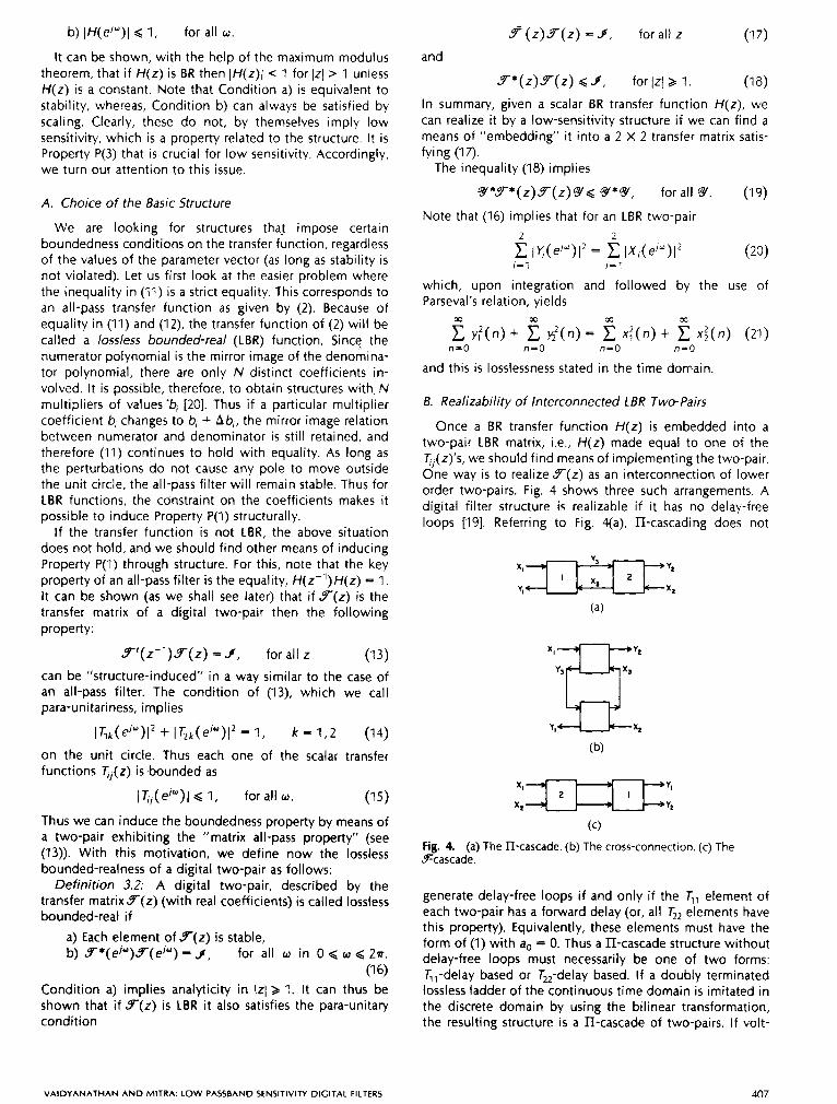
Once a BR transfer function H(z) is embedded into a two-pair LBR matrix, i.e., H(z) made equal to one of the T,,(z)'s, we should find means of implementing the two-pair. One way is to realize F ( z ) as an interconnection of lower order two-pairs. Fig. 4 shows three such arrangements. A digital filter structure is realizable if it has no delay-free loops [19]. Referring to Fig. qa), II-cascading does not
(c)
Fig. 4. (a) The ll-cascade. (b) The cross-connection. (c) The Scascade.
generate delay-free loops i f and only if the T,, element of each two-pair has a forward delay (or, all T,, elements have this property). Equivalently, these elements must have the form of (1) with do = 0. Thus a HI-cascade structure without delay-free loops must necessarily be one of two forms: T,,-delay based or T,,-delay based. If a doubly terminated lossless ladder of the continuous time domain is imitated in the discrete domain by using the bilinear transformation, the resulting structure is a II-cascade of two-pairs. If volt-
VAIDYANATHAN AND MITRA: LOW PASSBAND SENSITIVITY DIGITAL FILTERS 407
age and current are retained as flow variables in this struc- ture, it necessarily leads to delay-free loops [21].
IV. DIGITAL LBR TWO-PAIRS
We shall outline later the low-sensitivity realization of BR transfer functions using a cascaded LBR two-pair structure constrained at one end by a multiplier. In this section we outline the properties of the first-order reciprocal LBR two- pair which is one of the building blocks in our synthesis procedure. We also indicate certain LBR two-pair intercon- nections that preserve the LBR property.
A. Properties of LBR Two-Pairs
Recall that the LBR property involves stability and para- unitariness. Writing out the para-unitariness (see (17)) com- ponent by component we arrive at
For stability, zeros of A(z) must be in IzI < 1. We wish to rewrite the para-unitariness of Y(z ) in terms of the chain parameters. Substituting (5) in (22) we find
Cc+ I = A i (23a)
BE + ( A D - 6 C ) ( i b - st) = AS (23b)
[ ( A D - BC) = B . (23c)
It is shown in [21] that (22) implies
Tl&l = T22722 (24a)
7 3 2 = T21721. (24b)
Equation (24) along with (5) and (6) implies
Bb = Cc (25a)
( A D - BC)( Ab - st) = 1. (25b)
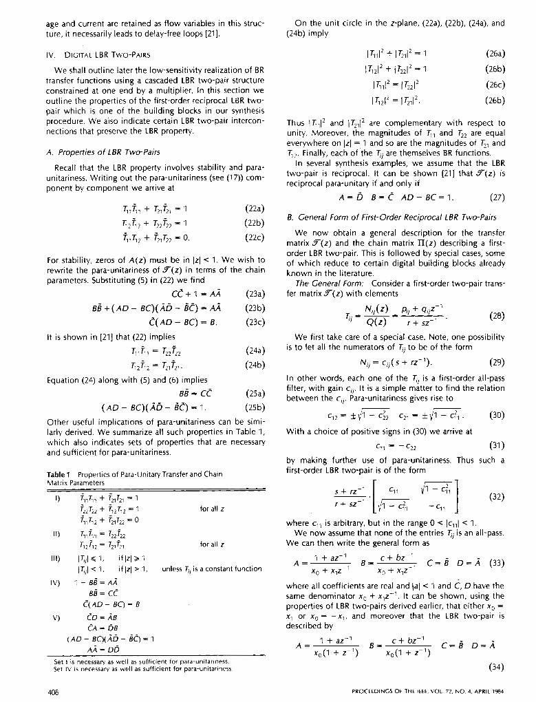
Other useful implications of para-unitariness can be simi- larly derived. We summarize all such properties in Table 1, which also indicates sets of properties that are necessary and sufficient for para-unitariness.
Table 1 Properties of Para-Unitary Transfer and Chain Matrix Parameters
V) &I = >B CA = D S
( A D - BC)(Ab - 6 0 1 AA = DE
Set IV is necessary as well as sufficient for para-unitariness. Set 1 i s necessary as well as sufficient for para-unitariness.
On the unit circle in the z-plane, (22a), (22b), (24a), and (24b) imply
I %I2 + I T21I2 = 1 (26a)
l T 2 I 2 + lT2*I2 = 1 (26b)
l G 1 I 2 = l 7 i 2 I 2 (26c)
I ? A 2 = I 7il12. (26b)
Thus \ ? , I 2 and lTZll2 are complementary with respect to unity. Moreover, the magnitudes of T,, and T,, are equal everywhere on IzI = 1 and so are the magnitudes of T,, and q,. Finally, each of the Ti are themselves BR functions.
In several synthesis examples, we assume that the LBR two-pair is reciprocal. It can be shown [21] that Y ( z ) is reciprocal para-unitary if and only if
A = b B = c A D - B C = I . (27)
B. General Form of First-Order Reciprocal LBR Two-Pairs
We now obtain a general description for the transfer matrix Y(z ) and the chain matrix n ( z ) describing a first- order LBR two-pair. This is followed by special cases, some of which reduce to certain digital building blocks already known in the literature.
The General Form: Consider a first-order two-pair trans- fer matrix Y ( z ) with elements
Njj(z) pjj + 9jjz-1 T.. = - =
‘ I Q(z) r + sz-1 ’
We first take care of a special case. Note, one possibility is to let all the numerators of Ti to be of the form
N,, = c j j ( s + rz-’). (29)
In other words, each one of the Ti is a first-order ail-pass filter, with gain cj j . It is a simple matter to find the relation between the c j j . Para-unitariness gives rise to
c12 = k {x c2, = k {x. (30)
With a choice of positive signs in (30) we arrive at
c11 = - c22 (31 1 by making further use of para-unitariness. Thus such a first-order LBR two-pair is of the form
where cll is arbitrary, but in the range 0 < ( C , ~ I < 1.
We can then write the general form as We now assume that none of the entries T j is an all-pass.
1 + az-’ c + bz-’ A = B = C = D = A (33)
x0 + xlz-l x0 + x,z-1
where all coefficients are real and Jal < 1 and C, D have the same denominator x. + xlz-’. It can be shown, using the properties of LBR two-pairs derived earlier, that either x. = x1 or x. = - x , , and moreover that the LBR two-pair is described by
A = 1 + az-1
B = c S b z - ’ c=d o=A xo(l + z- ’ ) xo( l + z-1)
(34)
408 PROCEEDINGS OF THE IEEE, VOL. 72, NO. 4, APRIL 1984
for the case x. = x1 and by IX,(e/") l ' + IX,(e/")l' = Iyl(eju)12 + IY2(ejw)12
showing that the resulting two-pair is para-unitary. It can be easily verified, using the BR property of each T j of an LBR two-pair, that the IT-cascade is a stable structure. II-cascad- ing, therefore, preserves LBR property.
b) Cross-connected LBR two-pairs (Fig. 4(b)): The LBR property of each two-pair implies
(X,(e/")12 + l ~ ~ ( e ' " ) / ~ = IQ(e'")12 + ~ ~ , ( e / " ) l '
and
IY3(e/")I2 + IX2(e/")12 = Iy(e'")l' + ~ ~ ~ ( e ' " ) l ~ .
The preceding equations leads to
IXl(ej")12 + ~ ~ , ( e ' " ) l ' = I q ( e j " ) l ' + Iyz(e'Y)12
showing that the resulting two-pair is para-unitary. More- over, the resulting two-pair can be proved to be stable and therefore LBR.
c) The Scascade interconnection: This is shown in Fig. 4(c), and is a conventional cascade of a multi-input, multi-output system. The overall transfer matrix is qq which leads to
99-= gqqq = g q = 4
and therefore para-unitariness holds. Moreover, it i s easy to check that any pole in 9-also appears in 5 and/or 6. Hence stability condition is automatically met, preserving the LBR property.
Finally, it can be shown from the definition of LBR functions and matrices, that if the variable z-' is replaced by a scalar LBR function, the resulting matrix or function is still LBR. (Such a substitution can be made on the structure itself, provided that it does not generate delay-free loops.)
An arbitrary combination of these interconnections also preserves LBR property. It is thus clear that we have poten- tially several possible structures that can exhibit low pass- band sensitivity. A particular interconnection, namely the II-cascade, gives rise to lattice structures [Ill, and many of the wave digital filter structures [ 2 ] , [6].
1 + az-' c + bz-l A = B = C = j D = A
xo(l - 2-1) x,(l - z-7)
(35) for the case where x. = -x1. Here, the constant "a" must satisfy la1 < 1 (to ensure stability). For the case where x. = x l , the parameter c has to satisfy
c = 5 - I - a I - k
and x. is obtained from
x 0 = * - (1 + a)' - ' d (I + k)'(I - a)' 2 (1 - k)' (37)
For the case x. = -x1, similar relations can be derived. Two points worth noting from the general form of the
first-order reciprocal two-pair are as follows: a) T,, and 5, must have a zero at z = 1 or -1, unless the entries T,, are all all-pass functions. These are the transmission zeros. b) The choice of suitable sign parameters may sometimes be useful in the choice of one of several equivalent structures. This is somewhat analogous to the situation which arises in the Gray and Markel lattices, where suitable choice of sign parameters leads to improved internal scaling [IO]. We now turn to certain special cases of the general form.
T,,-delaybased structures: It can be shown using the above formulation that if the first-order LBR two-pair has a pure delay in the numerator of T,, then the two-pair has the form
A = * 1 + az-1 *(I - a)z-'
6 ( 1 + 2-1) &(I + 2 - 7 ) B =
+(I - a ) a + 2-1 c= - *&(I + z-1) &(I + z-1)
D = (38)
or equivalently, in terms of the transfer parameters,
T,, = k I - a
1 + az-1
&(I + 2-1) T,, = T,, = * 1 + az-7
T,, = T (I - a)z-' 1 + az-' '
(39)
Note again the choice of various signs that is available to us. One explanation is that the properties of a reciprocal LBR two-pair are not affected if both A and D or both Cand B change sign.
Similarly, expressions can be derived for the parameters of a two-pair with a forward delay in Tl.
Interconnection of LBR Two-Pairs: Given a higher order two-pair, a convenient way of implementing it, is by inter- connecting lower order two-pairs. We next describe inter- connection schemes that preserve the LBR property.
a) The II-cascade (Fig. 4(a)): By para-unitary property of each LBR two-pair we have:
and
for all o. Combining these equations we arrive at
V. SYNTHESIS OF LBR FUNCTIONS
In this section we introduce the procedure for synthesis of a scalar LBR function as a 11-cascade of LBR two-pair structures, terminated in a constant LBR function (i.e., a multiplier of value 1 or -1). The principles introduced here are extensively used in the succeeding section for the synthesis of general BR transfer functions.
A. The LBR-Generated Class
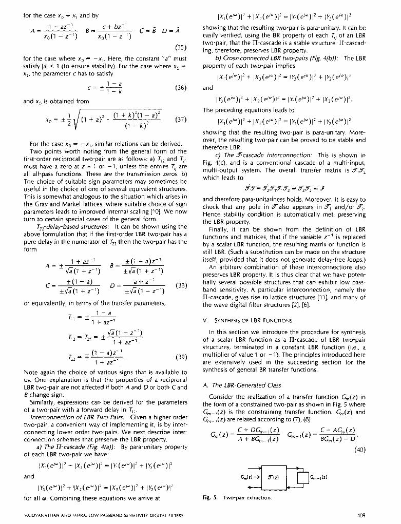
Consider the realization of a transfer function C,(z) in the form of a constrained two-pair as shown in Fig. 5 where G,,-,(z) is the constraining transfer function. G,(z) and G,-,(z) are related according to (7, (8)
Fig. 5. Two-pair extraction
V A I D Y A N A T H A N A N D M I T R A . LOW PASSBAND SENSITIVITY DIGITAL FILTERS
I I C*w GJZ)
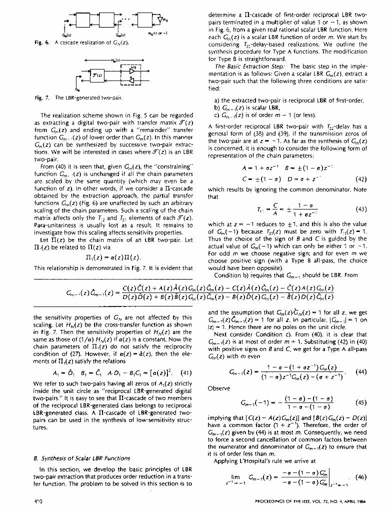
Fig. 6. A cascade realization of GN(z).
Fig. 7. The LBR-generated two-pair.
The realization scheme shown in Fig. 5 can be regarded as extracting a digital two-pair with transfer matrix F ( z ) from G,,,(z) and ending up with a “remainder” transfer function G,,-,(z) of lower order than G,,,(z). In this manner G,,,(z) can be synthesized by successive two-pair extrac- tions. We will be interested in cases where F ( z ) is an LBR two-pair.
From (40) it is seen that, given G,(z), the “constraining” function G,,,-,(z) is unchanged if all the chain parameters are scaled by the same quantity (which may even be a function of z). In other words, if we consider a II-cascade obtained by the extraction approach, the partial transfer functions G,,,(z) (Fig. 6) are unaffected by such an arbitrary scaling of the chain parameters. Such a scaling of the chain matrix affects only the 6, and T,, elements of each F(z ) . Para-unitariness is usually lost as a result. It remains to investigate how this scaling affects sensitivity properties.
Let II(z) be the chain matrix of an LBR two-pair. Let ll,(z) be related to I I ( z ) via
l l , ( Z ) = . ( z ) l l ( z ) .
This relationship is demonstrated in Fig. 7. It is evident that
determine a II-cascade of first-order reciprocal LBR two- pairs terminated in a multiplier of value 1 or -1, as shown in Fig. 6, from a given real rational scalar LBR function. Here each G,,,(z) is a scalar LBR function of order m. We start by considering T,,-delay-based realizations. We outline the synthesis procedure for Type A functions. The modification for Type B is straightforward.
The Basic Extraction Step: The basic step in the imple- mentation is as follows: Given a scalar LBR Gm(z), extract a two-pair such that the following three conditions are satis- fied:
a) the extracted two-pair is reciprocal LBR of first-order, b) Gm-l(z) is scalar LBR, c) G,,-,(z) is of order m - 1 (or less).
A first-order reciprocal LBR two-pair with T,,-delay has a general form of (38) and (39), if the transmission zeros of the two-pair are at z = -1. As far as the synthesis of G,,,(z) is concerned, it is enough to consider the following form of representation of the chain parameters:
A x 1 +uz-’ 6 = *(I - 6 ) z - l
C = *(I - u ) D = u + z - ’ (42) which results by ignoring the common denominator. Note that
C I - a A 1 + uz-l
T,, = - = * (43)
which at z = -1 reduces to +I, and this is also the value of G,,,(-I) because T,,(z) must be zero with T,,(z) = 1. Thus the choice of the sign of 6 and C is guided by the actual value of G,,,(-l) which can only be either 1 or -1. For odd m we choose negative sign; and for even m we choose positive sign (with a Type B all-pass, the choice would have been opposite).
Condition b) requires that G,,,-, should be LBR. From
c ( z ) C ( Z ) + A(z)~(z)G, , , (z)C, , , (Z) - c ( z ) ~ ( z ) C , , , ( Z ) - C ( Z ) A ( Z ) G , ( Z ) G-n-l(Z)Gn-l(z) D ( z ) ~ ( z ) + ~ ( z ) ~ ( z ) G , ( z ) C , , , ( Z ) - B(z)B(z)G, (z ) - B(z)D(z)C, (Z)
the sensitivity properties of GN are not affected by this scaling. Let HN(z) be the cross-transfer function as shown in Fig. 7. Then the sensitivity properties of HN(z) are the same as those of ( l / a ) HN(z) if a(z ) is a constant. Now the chain parameters of l l l ( z ) do not satisfy the reciprocity condition of (27). However, i f a(z ) = &(z), then the ele- ments of &(z) satisfy the relations
A, = dl B, = cl AIDl - B,C, = [ ~ ( z ) ] ’ . (41) We refer to such two-pairs having all zeros of Al(z) strictly inside the unit circle as “reciprocal LBR-generated digital two-pairs.” It is easy to see that ll-cascade of two members of the reciprocal LBR-generated class belongs to reciprocal LBR-generated class. A ll-cascade of LBR-generated two- pairs can be used in the synthesis of low-sensitivity struc- tures.
6. Synthesis of Scalar LBR Functions
In this section, we develop the basic principles of LBR two-pair extraction that produces order reduction in a trans- fer function. The problem to be solved in this section is to
and the assumption that G,(z )~ , , , (z ) = 1 for all z, we get G,,,.-,(Z)G,,,-~(Z) = 1 for all z. In particular, IGm-ll = 1 on JzI = 1. Hence there are no poles on the unit circle.
Next consider Condition c). From (a), i t is clear that G,,,-,(z) is at most of order m + 1. Substituting (42) in (40) with positive signs on 6 and C, we get for a Type A all-pass G,,,(z) with rn even
Gm-,(z) = I - u -(I + UZ-’)G,, ,(Z)
’ (44) (1 - u)z- lGm(z) -(u + z-1)
Observe
G,,,-,(-I) = - ( 1 - u) -(I - u) 1 -u-(I -u) (45 1
implying that [ C(z) - A(z)G,,,(z)] and [ B(z)G,,,(z) - D(z)] have a common factor (1 + z-’). Therefore, the order of G,-,(z) given by (44) is at most m. Consequently, we need to force a second cancellation of common factors between the numerator and denominator of Gm-l(z) to ensure that it is of order less than m.
Applying L’Hospital’s rule we arrive at
41 0 PROCEEDINGS OF THE IEEE, VOL. 72, N O . 4, APRIL 1984
To force the second cancellation, we set
(47)
It can be shown [21] that this choice of u leaves a remainder G,,-,(z) which is stable and hence LBR. With u as given above, a second application of L'Hospital's rule results in
-(I - 0)GE - 2uGh lim C,,,-,(z) =
z-1- -1 2(1 - u)G;, -(I - U)GG z - l = - l
= -1 (48)
by Lemma A.l of Appendix I. Thus we have established general conditions for successful extraction.
Another important fact that follows from the properties of scalar BR functions is that the parameter u defined by (47) satisfies
O , < U < l (49)
which is a consequence of Lemma A.2 of Appendix I. Now u = 0 implies T,, = T,, = 0, which is a degenerate case in the sense that the extracted two-pair completely isolates the circuit on its right from that at its left. On the other hand, if u = 1 then TI, = T2, = 0 and q2 = T,, = il which implies that there is no progress in the extraction scheme. Therefore, we hereafter ignore the possibility of any equal- ity in the inequality (49), and assume 0 < u < 1.
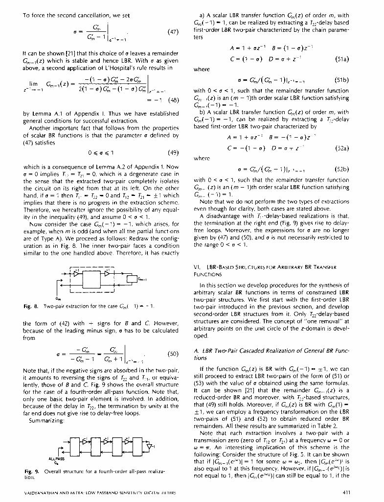
Now consider the case Gm(-l) = -1, which arises, for example, when m is odd (and when all the partial functions are of Type A). We proceed as follows: Redraw the config- uration as in Fig. 8. The inner two-pair faces a condition similar to the one handled above. Therefore, it has exactly
Fig. 8.
G, r- Two-pair extraction for the case C,,,-l) = -1
the form of (42) with + signs for B and C. However, because of the leading minus sign, u has to be calculated from
Note that, i f the negative signs are absorbed in the two-pair, it amounts to reversing the signs of T,, and q,, or equiva- lently, those of B and C. Fig. 9 shows the overall structure for the case of a fourth-order all-pass function. Note that, only one basic two-pair element is involved. in addition, because of the delay in T,,, the termination by unity at the far end does not give rise to delay-free loops.
Summarizing:
ALLPASS 64
Fig. 9. Overall structure for a fourth-order all-pass realiza- tion.
a) A scalar LBR transfer function G,,,(z) of order m, with Gm(-l) = 1, can be realized by extracting a T,,-delay based first-order LBR two-pair characterized by the chain parame- ters
A = 1 + UZ-' B = (1 - u)z-'
C = ( l - u ) D = u + z - ' (51 a)
where
u = G;,/( G;, - l ) l z - l = - , (51 b)
with 0 u 1, such that the remainder transfer function G,,-,(z) is an ( m - 1)th order scalar LBR function satisfying
b) A scalar LBR transfer function G,,,(z) of order m, with G,,,(-I) = -1, can be realized by extracting a TJJ-delay based first-order LBR two-pair characterized by
Gm-,(-l) = -1.
A 1 + UZ- ' B = -(I - u)z-'
C = -(I - U) D = u + Z-' (52a)
where
u = G,!,,/( G,!,, + I)lz-l=-l (52b)
with 0 < u < 1, such that the remainder transfer function G,,,- l(z) is an ( m - 1)th order scalar LBR function satisfying
Note that we do not perform the two types of extractions even though for clarity, both cases are stated above.
A disadvantage with T,,-delay-based realizations is that, the termination at the right end (Fig. 9) gives rise to delay- free loops. Moreover, the expressions for u are no longer given by (47) and (50), and u is not necessarily restricted to the range 0 < u < 1.
Gm-,(- l) = 1.
VI. LBR-BASED STRUCTURES FOR ARBITRARY BR TRANSFER FUNCTIONS
In this section we develop procedures for the synthesis of arbitrary scalar BR functions in terms of constrained LBR two-pair structures. We first start with the first-order LBR two-pair introduced in the previous section, and develop second-order LBR structures from it. Only T,,-delay-based structures are considered. The concept of "one removal" at arbitrary points on the unit circle of the z-domain is devel- oped.
A. LBR Two-Pair Cascaded Realization of General BR Func- tions
If the function G,(z) is BR with Gm(-l) = $1, we can still proceed to extract LBR two-pairs of the form of (51) or (53) with the value of u obtained using the same formulas. It can be shown [21] that the remainder G,,,-,(z) is a reduced-order BR and moreover, with T,,-based structures, that (49) still holds. Moreover, if G,,,(z) is BR with G,(l) = 51, we can employ a frequency transformation on the LBR two-pairs of (51) and (52) to obtain reduced order BR remainders. All these results are summarized in Table 2.
Note that each extraction involves a two-pair with a transmission zero (zero of 6 , or T,,) at a frequency w = 0 or w = n. An interesting implication of this scheme is the following: Consider the structure of Fig. 5. It can be shown that if IG,,,-,(e'")l = 1 for some w = wo, then IG,,,(e/")I is also equal to 1 at this frequency. However, if IG,,,-,(e'"o)l is not equal to 1, then IG,(ej"O))l can still be equal to 1, if the
V A I D Y A N A T H A N A N D M I T R A LOW PASSBAND SENSlTlLlTY DIGITAL FILTERS 41 1
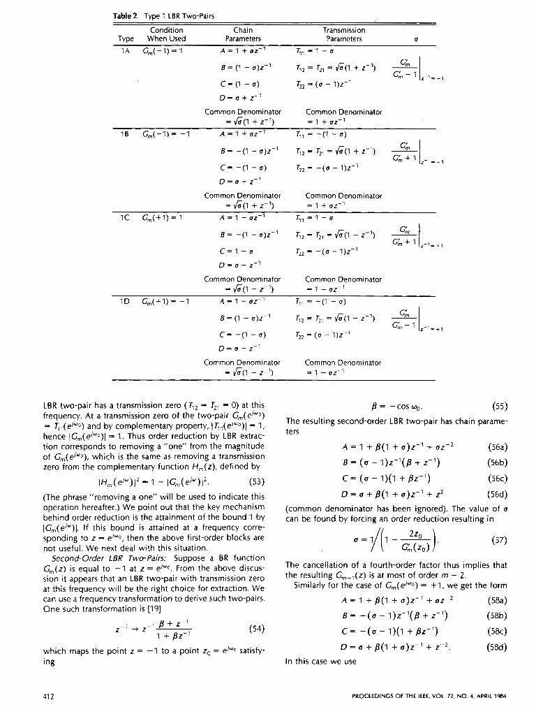
Table 2 Type I LBR Two-Pairs
Condition Chain Transmission Type When Used Parameters Parameters 0
1A G,,,(-l) = 1 A = 1 + az-' r , , = l - u
8 = (1 - 0)z-l r,, = r,, = 6(1 + z-') c = (1 - a) r,, = (U - 1)z-l
D = u + z-'
Common Denominator Common Denominator = 6(l + z-1) = 1 + uz-1
16 G,,,(-l)= -1 A = 1 + uz-' r,, = -(I - a) P, I
8 = -(I - a)z-l q 2 = T,, = 6 ( 1 + z-1)
c= -(I - (I) rZ2 = - (a - 1)z-l
D = u + z-l
Common Denominator Common Denominator = 6 ( 1 + z-1) = 1 + uz-1
I C G,,,(+l) = 1 A = 1 - UZ-' r , , = 1 - u P I I
B = -(1 - u)z-' T, = T,, = 6 ( 1 - z - ~ ) +1
C = l - u Tz2 = - ( a - 1)z-l D = a - z-l
Common Denominator Common Denominator = vG(1 - z-1) = 1 - (Jz-l
1D G,,,(+l)= - 1 A = l -uz-' T,, = -(I - u )
B = (1 - o)z-l T,, = T,, = vG(1 - z-1)
c= -11 - u ) r2, = (a - 1)z-l D = ( J - z-l
Common Denominator Common Denominator = J;;(l - z-1) = 1 - uz-1
LBR two-pair has a transmission zero (T,, = T,, = 0) at this frequency. At a transmission zero of the two-pair G,,,(eiwo) = T,,(ej"O) and by complementary property, IT,l(e/wO)l = 1 , hence IG,,,(ej"o)I = 1 . Thus order reduction by LBR extrac- tion corresponds to removing a "one" from the magnitude of G,,,(eJ"o), which is the same as removing a transmission zero from the complementary function H,,,(z), defined by
~ ~ , , , ( e j ~ ) ] ' = I - IG,,,(e'")12. (53)
(The phrase "removing a one" will be used to indicate this operation hereafter.) We point out that the key mechanism behind order reduction is the attainment of the bound 1 by IG,,,(ejU)l. If this bound is attained at a frequency corre- sponding to z = ejwo, then the above first-order blocks are not useful. We next deal with this situation.
Second-Order LBR Two-Pairs: Suppose a BR function G,(z) i s equal to -1 at z = ej"0. From the above discus- sion it appears that an LBR two-pair with transmission zero at this frequency will be the right choice for extraction. We can use a frequency transformation to derive such two-pairs. One such transformation is [I91
which maps the point z = -1 to a point zo = ej'o satisfy- ing
= -cosw,. (55)
The resulting second-order LBR two-pair has chain parame- ters
A = 1 + B(1 + u ) z - l + U Z - ~ (564
B = (U - I ) Z - ' ( ~ + 2-l) (56b)
c = (u - 1)(1 + Bz-1) (564
D = u + B(1 + u)z-' + Z' (564
(common denominator has been ignored). The value of a can be found by forcing an order reduction resulting in
(57)
The cancellation of a fourth-order factor thus implies that the resulting G,,,-,(z) is at most of order m - 2.
Similarly for the case of G,,,(eiwo) = + I , we get the form
A = 1 + p(1 + u)z-' + UZ-' (584
B = - (u - 1 ) Z - y p + z-1) (58b)
c - -(u - 1)(1 + pz-1) ( 5 k )
D = u + B(1 + u ) z P 1 + z-,. ( 5 8 4 In this case we use
41 2 PROCEEDINGS OF THE IEEE, VOL. 72, NO. 4, APRIL 1984
u = I/(? +A). Gl!ll(ZC>
It can be shown [21] that even though zo and G;(z,) are in general complex numbers, the quantity u in (57) and (59) is real. Moreover, u is in the range
O < U < l . (60)
Furthermore it can be shown that, with the above choice of (I, Gm-l is a BR function.
At this point, we have rules for order reduction of a BR function whose value is 1 or -1 somewhere on the unit circle. Table 3 summarizes the results of this subsection, and indicates the common denominator of the chain parameters which forces the condition AD - 5C= 1. Be- fore proceeding further, we consider a synthesis example.
Example 6.1: Consider the transfer function
22 - 52-1 + 5z-2 + 8z-3 = 24 - S2-1 + 5 z - 2 + loz-, '
It can be verified that this is a BR function with G3( - 1) = 1 and G3( e*'"/3) = 1. Let us first extract a second-order two- pair with transmission zeros at zo = Calculation shows that zo/C(zo) = 3/2 and therefore
1 1 u = = -
I + 2 ( $ j 4
In addition
Upon extraction of the following two-pair (Table 3, entry 1)
C = b , D = / i we get the first-order BR function
Since G,(-I) = 1, and G(-l) = -1, we can extract the two-pair in the first entry of Table 2 with
The two-pair is described by
A E 1 + 12-1 5 = 1 z - l C = j D = j 2 2
and the remainder function is = 4. Now consider the following situation: Given a BR func-
tion G(z), let the order be reduced by successive extrac- tions of LBR two-pairs until we get a BR function G,(z) with G,(z) # 1 or -1 at any point on the unit circle. The rules we have formulated so far do not cover this particular situation, and we need a new procedure for order reduc- tion. Two cases can be further identified as far as this situation is concerned
CASE I: There exists a point on the unit circle, zo = elWo such that (G(e'"'0)l = 1. CASE /I: IC(z)[ is nowhere unity on the unit circle.
The next subsection takes care of CASE I. More General "One Removals": Given a BR function
G,(z) such that (C,(el'"O)l = 1, our aim is to extract a first-order two-pair and force G,-l(ejwO) = 1 or -1. We can then extract a second-order two-pair for further order reduction. To consider this possibility first consider forcing Cm-l(e'wO) = -1. To this end we use the first-order two- pair of (51) but with u determined from
Note that this i s a real number. Table 4 summarizes various
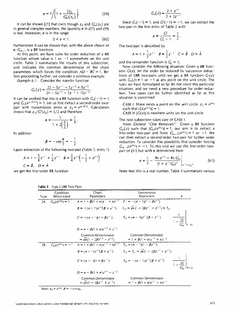
Table 3 Type 2 LBR Two-Pairs
Condition Chain Transmission Type When Used Parameters Parameters U
2A cm(e'yO) = 1 A = 1 + B(1 + 0)z-l + uz-, T,, = -(u - 1)(1 + B Z - l )
B = -(a - l)z-l(B + z-') T12 = fi(1 + 2Bz-l + Z-') = T,,
c = -(u - 1)(1 + Bz-1) T*? = ( 0 - l)z-'(/3 + z-1) -1
-I 1 --
1 + - (& z=zo
D = u + B(1 + 0)z-l + Z - *
Common Denominator Common Denominator = f i(1 + 2Bz-l + z-2) = 1 + j3(1 + 0)z-1 + uz-2
B = (U - I)z-'(B + z-') T,> = r,, = ficl + 2 ~ z - l + z - ~ )
c = (a - 1)(1 + Bz-') r,, = -(u - I)z- ' (B + z - ~ )
2B Gm(e'wo) = - 1 A = 1 + B(1 + 0)z-l + uz-' J,, = (u - 1)(1 + Bz-')
22 GA z=zo
D = (I + /?(I + 0)z-l + z - ~
Common Denominator Common Denominator = fi(1 + 2pz-1 + z-2) = 1 + B(1 + 0)z-l + uz-2
~~
Note: zo = e/-o, B = -cos wo
V A I D Y A N A T H A N A N D M I T R A LOW PASSBAND SENSITIVITY DIGITAL FILTERS 41 3
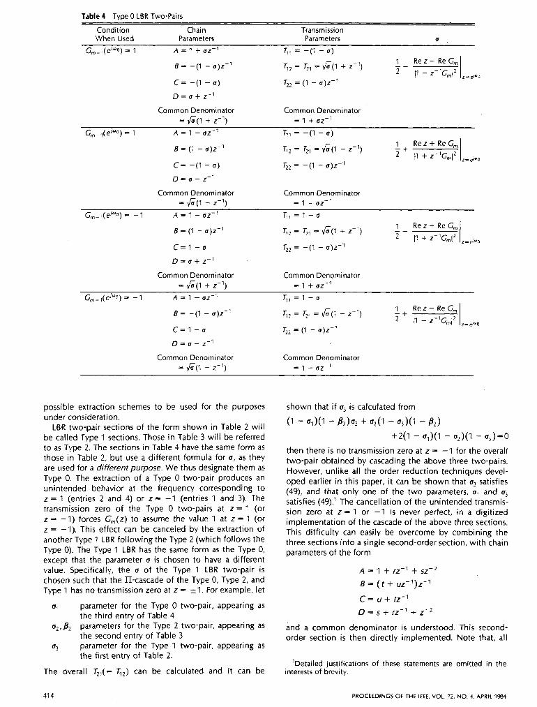
Table 4 Type 0 LBR Two-Pairs
Condition Chain Transmission When Used Parameters Parameters U
Gm-,(e”Q) = 1 A = 1 + uz-’ r,, = -(1 - a)
6 = - ( I - u)z-’
c = -(I - 6 )
D = u + z-l
Common Denominator Common Denominator = F(l + 2-1) = 1 + uz-1
G,,-,(ejOO) = 1 A = 1 - UZ-’ T’, = -(I - 6) 6 = (1 - u)z-’
c = - ( I - u )
D = a - z-’
Common Denominator Common Denominator = F ( 1 - 2 - 1 ) = 1 - uz-1
G,,-l(e/wo) = -1 A = 1 + u z - l r , , = l - u
6 = (1 - 0)z-l
c = 1 - u
D = u + 2-l
Common Denominator Common Denominator = F(l + 2-1) = 1 + uz-1
Gm-l(e/OO) = - 1 A = 1 - UZ-’ T , , = l - u
6 - ( I - u)z-’
c=1 - u r,, = (I - 0)z-l (I - z-’
Common Denominator Common Denominator = F(1 - 2-1) = 1 - uz-l
possible extraction schemes to be used for the purposes under consideration.
LBR two-pair sections of the form shown in Table 2 will be called Type 1 sections. Those in Table 3 will be referred to as Type 2. The sections in Table 4 have the same form as those in Table 2, but use a different formula for u, as they are used for a different purpose. We thus designate them as Type 0. The extraction of a Type 0 two-pair produces an unintended behavior at the frequency corresponding to z = 1 (entries 2 and 4) or z E= -1 (entries 1 and 3). The transmission zero of the Type 0 two-pairs at z = 1 (or z = -1) forces G,,,(z) to assume the value 1 at z = 1 (or z = -1). This effect can be canceled by the extraction of another Type 1 LBR following the Type 2 (which follows the Type 0). The Type 1 LBR has the same form as the Type 0, except that the parameter u is chosen to have a different value. Specifically, the u of the Type 1 LBR two-pair is chosen such that the II-cascade of the Type 0, Type 2, and Type 1 has no transmission zero at z = fl. For example, let
u1 parameter for the Type 0 two-pair, appearing as
u2,B2 parameters for the Type 2 two-pair, appearing as
a, parameter for the Type 1 two-pair, appearing as
the third entry of Table 4
the second entry of Table 3
the first entry of Table 2.
The Overall T21(= q,) can be calculated and it can be
41 4
shown that if a, is calculated from
- ul)(l - B 2 ) % + u2(1 - u3)(1 - 82) +2(1 - UJ(1 - u2)(1 - u,)=o
then there is no transmission zero at z = -1 for the overall two-pair obtained by cascading the above three two-pairs. However, unlike all the order reduction techniques devel- oped earlier in this paper, it can be shown that a, satisfies (49), and that only one of the two parameters, u1 and u3 satisfies (49).l The cancellation of the unintended transmis- sion zero at z = 1 or -1 is never perfect, in a digitized implementation of the cascade of the above three sections. This difficulty can easily be overcome by combining the three sections into a single second-order section, with chain parameters of the form
A = 1 + rz-l + szP2 6 = ( ? + uz-l)z-’
c = u + tz-1 D = s + rz-’ + z-,
and a common denominator is understood. This second- order section is then directly implemented. Note that, all
’Detailed justifications of these statements are omitted in the interests of brevity.
PROCEEDINGS OF THE IEEE, VOL. 72, NO. 4, APRIL 1584
our order reduction schemes are "one-removal" operations on the quantity IG,(ej")l.
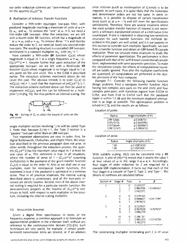
B. Realization of Arbitrary Transfer Functions
Consider a fifth-order equiripple low-pass filter, with passband magnitude reaching a maximum of unity at a,( = 0), w 2 , and w3. To remove the "one" at w, = 0, we need a first-order LBR two-pair. After this extraction, we are left with a fourth-order BR function, which has a magnitude of 1 at w = w2 and o = w 3 . To remove these "1"s and thereby reduce the order to 0, we need (at least) two second-order two-pairs. The resulting structure is a cascaded LBR two-pair, terminated in a constant multiplier m,, with ]mol < 1.
Next consider a fifth-order BR function G,(z) whose magnitude is equal to 1 at a single frequency w = wo, i.e., IGs(ei"O)l = 1. Assume further that upon extraction of the appropriate two-pair, we are left with a third-order BR function G,(z) whose magnitude is no longer equal to 1 at any point on the unit circle. This is the CASE I I described earlier. The extraction schemes mentioned above do not cover this case. The obvious remedy is to scale G,(z) to mG3(z), Iml > 1, such that the maximum of ImG3(ei")l is 1. The extraction scheme outlined above can then be used to implement mC3(z), and this can be followed by a multi- plier l / m (Fig. IO). We thus perform an internal scaling. The
c, $ 6 Fig. 10. Scaling of C, to attain the bound of unity on the unit circle.
single multiplier section involving l / m will be called Type 3. Note that, because p/mI < 1, the Type 3 section is a "passive" two-pair rather than an LBR two-pair.
Two important observations are now in order. First, for digital Butterworth, Chebyshev, and elliptic filters, the situa- tion described in the previous paragraph does not arise. In other words, throughout the extraction process, the quan- tity IGm(elw)I has the maximum value equal to 1 at least for one value of w . This statement is true in all situations, where the number of zeros of 1 - IG,(ej")l* (counting multiplicity) in the passband of the given transfer function GN(z) is equal to the order N. Also as we shall see in our examples, even for nonclassical transfer functions, this statement is true if the passband is optimized in a minimax sense. Thus in all practical situations, the internal scaling described above is unnecessary, and all the two-pairs in- volved are strictly lossless. Second, even if the above inter- nal scaling is required for a particular transfer function, the zero-sensitivity property at the maxima of IG,(e'")l con- tinues to hold, with respect to each multiplier in the struc- ture, including the internal scaling multiplier.
VII. SIMULATION EXAMPLES
Given a digital filter specification in terms of the frequency response, a common approach is to formulate an approximation problem in the z-domain itself, without any reference to the continuous-time domain [13]-[16]. Such techniques are very useful, for example, i f certain prede- termined transmission zeros are desired, or if an arbitrary
error criterion (such as minimization of $-error) is to be imposed. In such cases, it is quite likely that the numerator and denominator orders are not the same. In some in- stances, it is possible to dispose of certain transmission zeros (such as at z = -1) and still meet the specifications satisfactorily. Therefore, there are several situations where the most suitable transfer function of interest is not neces- sarily a bilinearly transformed version of a continuous-time counterpart. If one is interested in obtaining low-sensitivity structures for such transfer functions, the methods de- scribed in this paper are well suited, and it is our purpose in this section to consider such examples. Specifically, we start from a transfer function and obtain an LBR-based II-cascade realization. Then we simulate these structures to study the effects of parameter quantization. The performance is then compared with that of the well-known conventional cascade form, implemented with same parameter precision. To make the simulations simple, the effects of computational round- off are totally ignored. Thus after the multiplier coefficients are quantized, all computations are performed at the dou- ble precision of the host computer.
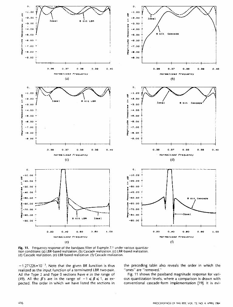
Example 7.7: Consider the following transfer function design problem. Find a bandpass transfer function H(z) having two complex zero pairs on the unit circle and four complex pole-pairs, with transition regions from 0.325~ to 0.35n, and from 0 . 4 ~ to 0.425~ such that the passband ripple is within 1.5 dB and the minimum stopband attenua- tion is as large as possible. This optimization problem is solved in [15], and the results are as follows:
Location of poles:
Radius Angle (multiples of n )
0.991 52666 kO.3506754 0.97675725 k 0.36450952 0.97706649 k0.38580674 0.991 727475 i 0.39934153
Location of zeros:
Radius Angle (multiples of a) 1 .oo kO.430034232 1 . o o k0.32053856
With suitable scaling, H(z) can be converted into a BR function. A plot of IH(e/")l reveals that it attains the value 1 at four values of w in the range 0 d w d n. Accordingly, four stages of order reduction by 2 are required for a cascade LBR implementation. It turns out that each of the four stages is a cascade of Type 0, Type 2, and Type 1. The details of synthesis are tabulated below:
Section # Stage # Type u B 1 1 0
2 2 3 1
2 4 0 5 2 6 1
3 7 0 8 2 9 1
4 10 0 11 2 12 1
0.3297277
3.0420370
0.3391165 0.5488027 - 0.41 11 997 2.9676622
0.3229327
3.0%2739
0.2861351 0.9852333 - 0.31 40784 3.4852315
0.9801 098 - 0.4491 427
0.9549500 -0.3529237
The constraining multiplier terminating port 2 is of value
V A I D Y A N A T H A N A N D M l T R A LOW PASSBAND SENSITI\ITY DIGITAL FILTERS 41 5
0.
t -1.00
-2.00 - 'I I d e a l . -3.00 I : - 4 . 0 0
P a 5 - 4 . 0 0
c! - 5 . 0 0 1
a
a" - 6 . 0 0
3 E -7.00 t
6 nit Cascade
i
i Y ," - 7 . 0 0
i -9.00 t
j - 8 . 0 0 + I
- 8 . 0 0
1 I
I I 1
0.38 0.37 0.38 0.39 0 . 4 0
Normal ized Frequency
(b)
0.38 0.37 0.38 0.39 0 . 4 0
Normal ized Freuuency
(a)
-1.00
D -2.00
'I I d e a l B nit L8R
-1.00
t -2.00
'I . -3.00 Ideal B bit Cascade ~ -3.00 t
2 - 5 . 0 0 + I
2 -4.00 t a
P
: n i - 4 . 0 0
g - 5 . 0 0 + P
t -8.00 f
I
3 - 7 . 0 0 t
C ." -8.00 t
I
I I
: ~ -7.00 i I !i - 8 . 0 0 f
-8 .oo
I
- 9 . 0 0 t
9.36 0.37 0.38 0.39 0 . 4 0
Normal ized Frequency
( 4
0.38 0.37 0.38 0.39 0 . 4 0
Normal lzcd FrcQuency
( 4
0 I 1 I I
t -io.oo
- 2 0 . 0 0
T
t -10.00
-20.00 - . -30.00 I :-40.00 a
pl-50.00
. -30.00 $ - 4 0 . 0 0 9
a-sO.OO ; -80. 00 3
- 7 0 . 0 0 C
p 3 0 . 0 0
-90.00
f - 8 0 . 00 3 2 - 7 0 . 0 0 i 2 - 8 0 . 0 0 i ~
I -eo.oo t
0.20 0 . 4 0 0.80 0 . 8 0 1.00
Normel lzed Frequency
(e)
Fig. 11. Frequency response of the bandpass filter of Example 7.1 under various quantiza- tion conditions: (a) LBR-based realization. (b) Cascade realization. (c) LBR-based realization. (d) Cascade realization. (e) LBR-based realization. (9 Cascade realization.
0 . 2 0 0 . 4 0 0 . 8 0 0 . 8 0 1.00
Normel ized Frequency
(9
-1.271226*10-3. Note that the given BR function is thus the preceding table also reveals the order in which the realized as the input function of a terminated LBR two-pair. "ones" are "removed." All the Type 2 and Type 0 sections have (I in the range of Fig. 11 shows the passband magnitude response for vari- (49). All the /3's are in the range of -1 6 /3 6 1, as ex- ous quantization levels, where a comparison is drawn with pected. The order in which we have listed the sections in conventional cascade-form implementation [19]. It is evi-
41 6 P R O C E E D I N G S OF THE IEEE, VOL. 72, N O 4, APRIL 1984
dent that the LBR-based structures have much better pass- band behavior. The stopband behavior is usually better for the conventional cascade form, as seen from the plots. The reason for this is that, in the conventional cascade structure, the parameter quantization does not move the transmission zeros away from the unit circle.
Two points are worth noting here. First, the order in which the "ones" are "removed" can be permuted, giving rise to 24 different structures. These structures may behave differently as far as other nonideal effects (such as roundoff noise) are concerned. Second, instead of quantizing all multipliers to the same number of bits, we can distribute a given number of total bits among the various multipliers according to an optimal bit assignment scheme. Further study is required along these lines. Such flexibilities are, of course, also available in the conventional cascade form structure.
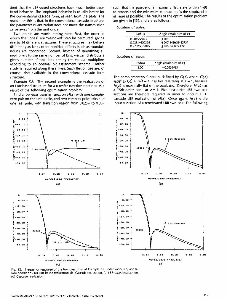
Example 7.2: The second example is the realization of an LBR-based structure for a transfer function obtained as a result of the following optimization problem:
Find a low-pass transfer function H(z) with one complex zero pair on the unit circle, and two complex pole-pairs and one real pole, with transition region from 0.025~ to 0 . 0 5 ~
O. 1--- I !
- 8 . 0 0 1
-12 .00 i 1
l- lO.oo - !! k-24 .00 - .Q
U - 3 0 . 0 0 f
t -30 .
2-40.
3 -42.
t
-54 .
00
00
00
00
\ B b i t LBR
I I I
such that the passband is maximally flat, stays within I-dB tolerance, and the minimum attenuation in the stopband is as large as possible. The results of the optimization problem are given in [15], and are as follows:
Location of poles:
Radius Angle (multiples of r)
0.904588023 0.9281 4900392
k 0.0 k0.01945638482737
0.97588677045 0.027468650688
Location of zeros:
Radius Angle (multiples of r)
1 .oo 0.053641 5
The complementary function, defined by C(z) where C(z ) satisfies GC + H i = 1, has five real zeros at z = 1, because H(z) is maximally flat in the passband. Therefore, H(z) has a "5th-order one" at z = 1. Five first-order LBR two-pair sections are therefore required in order to obtain a ll- caxade LBR realization of H(z). Once again, H(z) is the input function of a terminated LBR two-pair. The following
0.
-6 .00 P
-12.00
q
, -16.00
$ -24 .00
a
a
ao-30.00
$-38.00 3 E -42.00 C
%-40.00
-54 .00
0.04 0 . 0 0 0 . 1 2 0 . 1 6 0 . 2 0
Normal izea Frequency
(b)
0 .04 0 . O B 0 . l 2 0 . 1 0 0 . 2 0
NorrnaJizea Frequency
(a)
$ -36.00 3 E -42 .00 C
2-40.00
-54 .00
! - 6 .
-92.
" , - l e .
a
I 5 -24.
ao -30. d -38. 3 E -42. C
%-46.
-54.
O0 t 1: 1 00
00 10 bit Cascade
0 . 0 4 0 .00 0 . 1 2 0 . 1 6 0 . 2 0
Ncwmmlizea Frequency
(c) Fig. 12. Frequency response of the low-pass filter of Example 7.2 under various quantiza- tion conditions: (a) LBR-based realization. (b) Cascade realization. (c) LBR-based realization. (d) Cascade realization.
0 . 0 4 0 .00 0 . 1 2 0 . 1 8 0 . 2 0
Normal ized Frequency
( 4
V A I D Y A N A T H A N A N D M I T R A LOW PASSBAND SENSlTlVlrY DIGITAL FILTERS 41 7
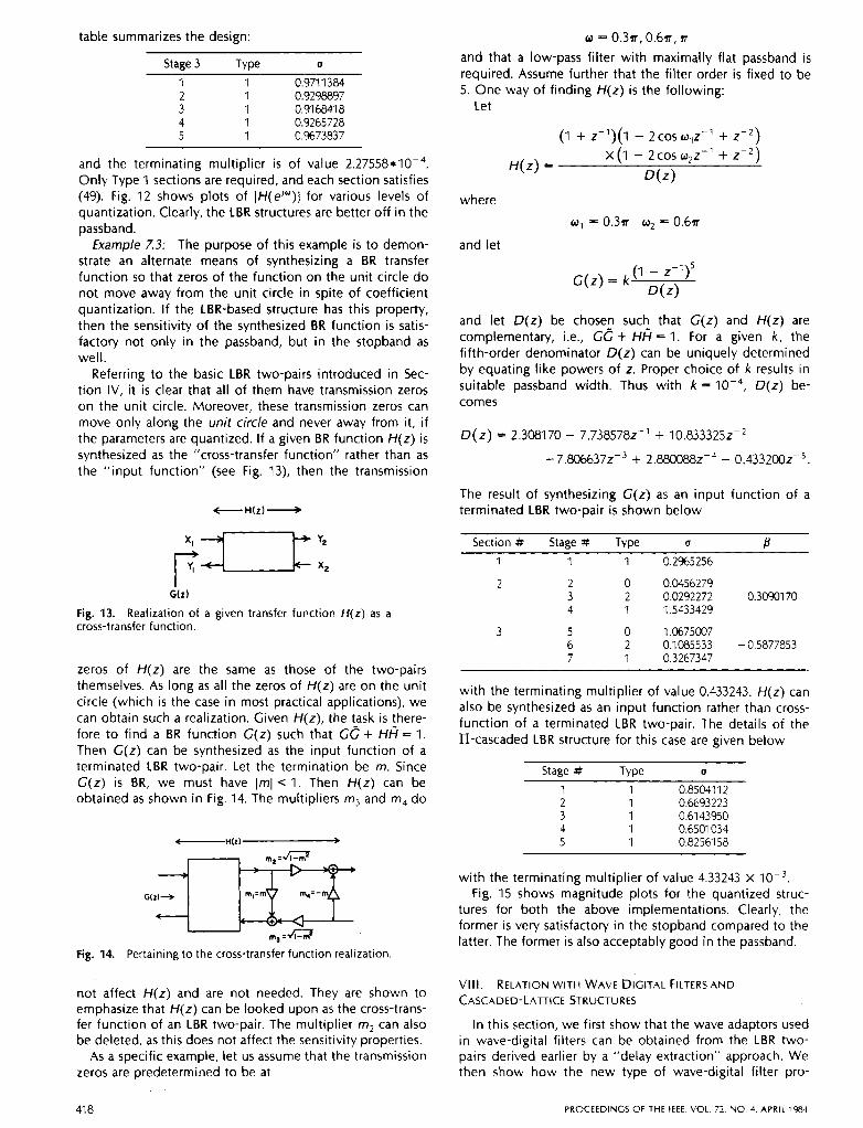
table summarizes the design:
Stage 3 Type U
1 1 0.9711 384 2 1 0.9298897 3 1 0.91 6841 8 4 1 0.9265728 5 1 0,9673837
and the terminating multiplier is of value 2.27558*10-4. Only Type 1 sections are required, and each section satisfies (49). Fig. 12 shows plots of IH(eJ“)l for various levels of quantization. Clearly, the LBR structures are better off in the passband.
Example 7.3: The purpose of this example is to demon- strate an alternate means of synthesizing a BR transfer function so that zeros of the function on the unit circle do not move away from the unit circle in spite of coefficient quantization. If the LBR-based structure has this property, then the sensitivity of the synthesized BR function is satis- factory not only in the passband, but in the stopband as well.
Referring to the basic LBR two-pairs introduced in Sec- tion IV, it is clear that all of them have transmission zeros on the unit circle. Moreover, these transmission zeros can move only along the unit circle and never away from it, if the parameters are quantized. If a given BR function H(z) is synthesized as the “cross-transfer function” rather than as the “input function” (see Fig. 13), then the transmission
G W
Fig. 13. Realization of a given transfer function H ( z ) as a cross-transfer function.
zeros of H(z) are the same as those of the two-pairs themselves. As long as all the zeros of H(z) are on the unit circle (which is the case in most practical applications), we can obtain such a realization. Given H(z), the task is there- fore to find a BR function G(z) such that G c + Hf i = 1. Then G(z) can be synthesized as the input function of a terminated LBR two-pair. Let the termination be m. Since G(z) is BR, we must have I r n l < 1. Then H(z) can be obtained as shown in Fig. 14. The multipliers m3 and m4 do
t - - - - H ( Z ) +
Fig. 14. Pertaining to the cross-transfer function realization.
not affect H(z) and are not needed. They are shown to emphasize that H(z) can be looked upon as the cross-trans- fer function of an LBR two-pair. The multiplier rn, can also be deleted, as this does not affect the sensitivity properties.
As a specific example, let us assume that the transmission zeros are predetermined to be at
w = 0.3n, 0.6n, B
and that a low-pass filter with maximally flat passband is required. Assume further that the filter order is fixed to be 5. One way of finding H(z) is the following:
Let
(1 + z-1)(1 - zcos 0,z-’ + z-2)
H(z) = x ( l - zcos 0,z-1 + 2-2)
D(z)
where
w1 = 0 . 3 ~ w2 = 0 . 6 ~
and let
G(z) = k (1 - z-7)’
D ( z )
and let D(z) be chosen such that G(z) and H(z) are complementary, i.e., G c + Hf i = 1. For a given k , the fifth-order denominator D(z) can be uniquely determined by equating like powers of z. Proper choice of k results in suitable passband width. Thus with k = D(z) be- comes
D ( z ) = 2.308170 - 7.7385782-’ + 10.833325~-~
- 7.806637~-~ + 2.880088~-~ - 0.433200~-~.
The result of synthesizing G(z) as an input function of a terminated LBR two-pair is shown below
Section # Stage # Type a B 1 1 1 0.2%5256
2 2 0 0.0456279 3 2 0.0292272 0.3090170 4 1 1.5433429
3 5 0 1.0675007 6 2 0.1085533 - 0.5877a53 7 1 0.3267347
with the terminating multiplier of value 0.433243. H(z) can also be synthesized as an input function rather than cross- function of a terminated LBR two-pair. The details of the II-cascaded LBR structure for this case are given below
Stage # Type a
1 1 0.85O4112 2 3
1 0.6693223 1 0.6143950
4 1 0.6501 034 5 1 0.8256158
with the terminating multiplier of value 4.33243 X Fig. 1 5 shows magnitude plots for the quantized struc-
tures for both the above implementations. Clearly, the former is very satisfactory in the stopband compared to the latter. The former is also acceptably good in the passband.
VIII. RELATION WITH WAVE DIGITAL FILTERSAND CASCADED-LATTICE STRUCTURES
In this section, we first show that the wave adaptors used in wave-digital filters can be obtained from the LBR two- pairs derived earlier by a “delay extraction” approach. We then show how the new type of wave-digital filter pro-
41 8 PROCEEDINGS OF THE IEEE. VOL 72, NO 4, APRIL 1984
a-30.00 - a $-40.00 - Ideal
I -80.00 .?
I 8 I
0 . 2 0 0 .40 0 . 6 0 0 . 6 0 1.00
Normalfrmd Frequmncy
(a)
0
3 -10
-20
a -30 e $ -40
2 8 -50
:-eo 3 E -70 C
E 2 -BO
17 .oo
.oo
. 00
.oo
.oo
.oo
. 00
. oo
-80.00 t
I 1 0 . 2 0 0.40 0.60 0 . 6 0 1.00
Normalfzed Frequency
(b) Fig. 15. Frequency response of the low-pass filter of Exam- ple 7.3 under various quantization conditions: (a) Transfer function realized as the cross-transfer function. (b) Transfer function realized as the input function.
posed in [6] can be obtained from the LBR two-pairs by means of "multiplier extraction" [22]. Consider the first- order LBR two-pair
P(z) = [; ;] with
T,al = 1 - u (1 + z-1)
= Tfl = 6 1 + uz-1 1 + uz-1
Tf2 = -(I - u)z-l 1 + uz-1 .
By scaling the corresponding chain parameters with a scale factor of 6, we generate another two-pair Y(z)
with
1 - u T,, = 72 =
51 = T22 =
u(1 + z-1) 1 + uz-1 1 + uz-l 1 + z-1 1 + uz-1 1 + uz-l
-(I - u)z-l . (62b)
r------l I I
L----L
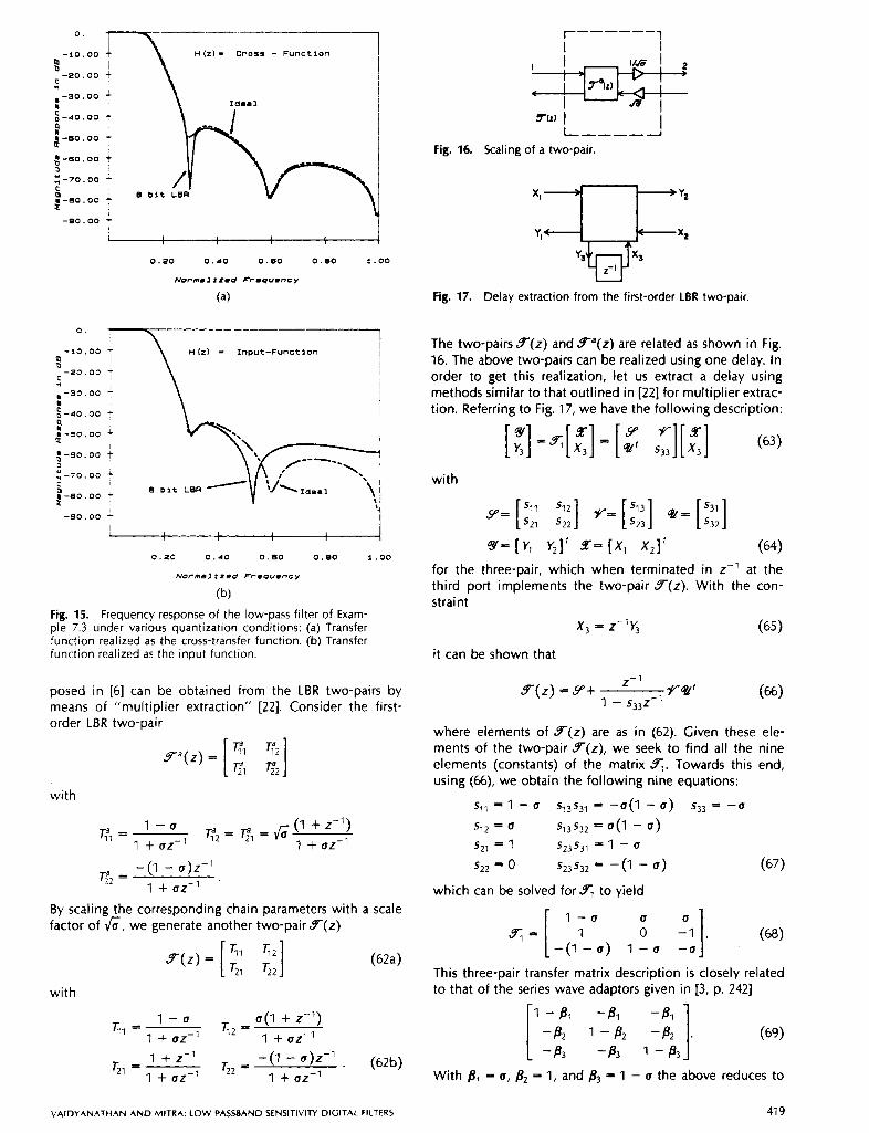
fig. 16. Scaling of a two-pair.
'J---$ 2-1
fig. 17. Delay extraction from the first-order LBR two-pair.
The two-pairs Y ( z ) and Yd(z) are related as shown in Fig. 16. The above two-pairs can be realized using one delay. In order to get this realization, let us extract a delay using methods similar to that outlined in [22] for multiplier extrac- tion. Referring to Fig. 17, we have the following description:
[ :] -.[:I = [*' 533][x3] (63) Y V Z
with
y= [ ::: :::I V- [:::I *- [:::I Y- [ v , v,]' Z= [x, x,]' (64)
for the three-pair, which when terminated in z-l at the third port implements the two-pair Y(z). With the con- straint
x, = z-16 (65 1 it can be shown that
Y(z) = Y+ Z-l VW
1 - 533z-1
where elements of Y(z) are as in (62). Given these ele- ments of the two-pair Y(z), we seek to find all the nine elements (constants) of the matrix q. Towards this end, using (66), we obtain the following nine equations:
I - a U 0 (68)
-(I - u ) 1 - u - u
This three-pair transfer matrix description is closely related to that of the series wave adaptors given in 13, p. 2421
1 - 8, -81 -81 [ -82 1-82 -82 1. (69) -83 -83 1 - 83
With F1 = u, B2 = 1, and & = 1 - u the above reduces to
V A I D Y A N A T H A N A N D M I T R A : LOW PASSBAND SENSITIVITY DIGITAL FILTERS 41 9
1 - 0 -U 0 "1. (70)
-(I - u ) -(I - u ) u
Now, we get from the definition of Yl and (68)
[ -;2]= [ l1lU -U
-U
0 -I][ -g (71) -(I - u ) -(I - u ) u
Thus the matrix appearing in (71) is the same as$ of (70) and so the adaptors are obtained in a systematic way from the LBR approach. Moreover, we are naturally led to a one-multiplier description, advanced by Fettweis [23]. The changes in sign are easily explained: The changes in X , and Y, do not affect the function to the right of port 2. If we had extracted -2-l instead of z-', the change in sign of X , would have been unnecessary.
Instead of starting from the LBR-generated two-pair of (62), if we start from the LBR two-pair Y'(z) itself, we get the three-pair
qa = 1 - u 0 -61. (72) -(I - u ) - - u 6
Moreover, from (66), it is clear that Y(z) is not affected by inserting an arbitrary scale factor a in c to get a new matrix qb as follows:
6 u/a 1 q b =
0 1 - 0 - a -u 6
It can be shown that if a is chosen as
a = 1 - u (74)
then qb satisfies LBR property, i.e., (qb)'qb = Y. Essen- tially, this means that c is an LBR-generated three-pair. Thus the series adaptor can be looked upon as an LBR-gen- erated three-pair of zero order. In view of the equivalence between parallel and series adaptors,pointed out in [23], it follows that the parallel adaptor can also be derived directly via the LBR approach.
We can similarly extract delays from two-pairs of higher order described in the previous section and obtain corre- sponding adaptors. For example, consider the Brune section of continuous-time domain. If the delays representing the inductors and capacitors in an equivalent wave-digital sig- nal flow diagram are extracted, the remaining circuit is the adaptor described in [24]. The same adaptor can be ob- tained using the LBR approach, by extracting delays from a ll-cascade of Type 0, Type 2, and Type 1 sections described in the previous section.
In a manner similar to the delay extraction, we can extract a multiplier and obtain from (62) the three-pair (which gives the structure shown in Fig. 18)
s;= 1 0 1
(1 + z-I) -2-1 z-1 -(I + 2 - 1 ) 1 + z-1 -z-l
1 1. (75)
1
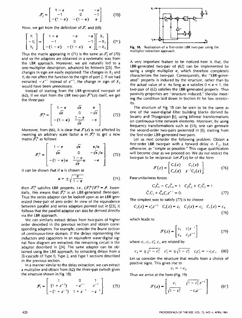
Fig. 18. Realization of a first-order LBR two-pair using the multiplier extraction approach.
A very important feature to be noticed here is that, the LBR-generated two-pair of (62) can be implemented by using a single multiplier u, which therefore completely characterizes the two-pair. Consequently, the "LBR-gener- ated" property is induced by the structure, rather than by the actual value of u. As long as u satisfies 0 c u c 1, the two-pair of (62) satisfies the LBR-generated property. Thus passivity properties are "structure induced," thereby meet- ing the condition laid down in Section Ill for low sensitiv- ity.
The structure of Fig. 18 can be seen to be the same as one of the wave-digital filter building blocks derived by Swamy and Thyagarajan [6], using bilinear transformations on continuous-time network elements. Moreover, by using frequency transformations such as (54), one can generate the second-order two-pairs presented in [6], starting from the first-order LBR-generated two-pairs.
Let us next consider the following problem: Obtain a first-order LBR two-pair with a forward delay in TZ2, but otherwise, as "simple as possible." This vague qualification will become clear as we proceed on. We do not restrict the two-pair to be reciprocal. Let Y ( z ) be of the form
Para-unitariness forces
clcl + c,c, = 1 c2c2 + c3c3 = 1
The simplest way to satisfy (77) is to choose
C,(Z) = ci2-l C,(Z) = c, C2(Z) = c, C,(Z) = cq
which leads to
(79)
where c,, c2, &, c, are related by
Let us consider the structure that results from a choice of positive signs. This gives rise to
c, = -c2.
Thus we arrive at the form (Fig. 19)
420 PROCEEDINGS Of THE IEEE, VOL. 72, NO 4, APRIL 1984
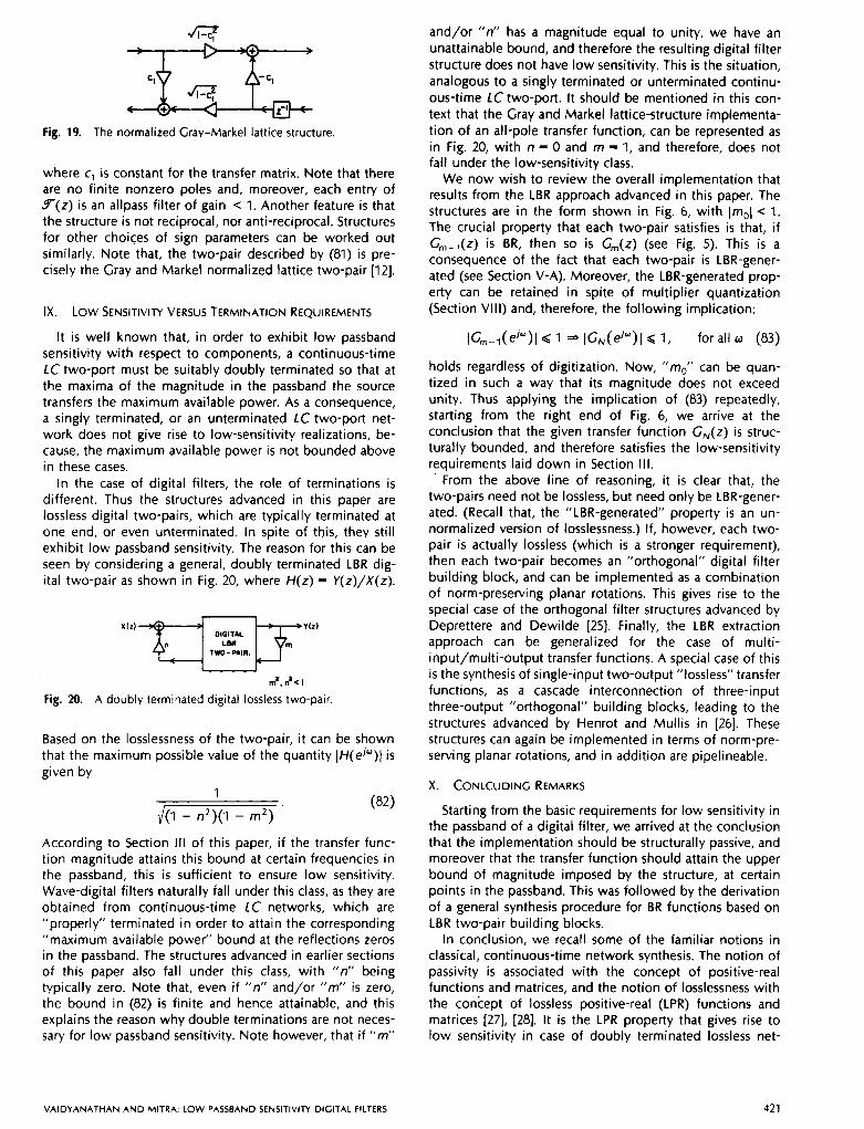
Fig. 19. The normalized Gray-Markel lattice structure
where c1 is constant for the transfer matrix. Note that there are no finite nonzero poles and, moreover, each entry of Y ( z ) i s an allpass filter of gain 1. Another feature is that the structure is not reciprocal, nor anti-reciprocal. Structures for other choices of sign parameters can be worked out similarly. Note that, the two-pair described by (81) is pre- cisely the Gray and Markel normalized lattice two-pair [12].
IX . Low SENSITIVITY VERSUS TERMINATION REQUIREMENTS
It is well known that, in order to exhibit low passband sensitivity with respect to components, a continuous-time LC two-port must be suitably doubly terminated so that at the maxima of the magnitude in the passband the source transfers the maximum available power. As a consequence, a singly terminated, or an unterminated LC two-port net- work does not give rise to low-sensitivity realizations, be- cause, the maximum available power is not bounded above in these cases.
In the case of digital filters, the role of terminations is different. Thus the structures advanced in this paper are lossless digital two-pairs, which are typically terminated at one end, or even unterminated. In spite of this, they still exhibit low passband sensitivity. The reason for this can be seen by considering a general, doubly terminated LBR dig- ital two-pair as shown in Fig. 20, where H(z) = V(z) /X(z ) .
In*, A I Fig. 20. A doubly terminated digital lossless two-pair.
Based on the losslessness of the two-pair, it can be shown that the maximum possible value of the quantity IH(e’“)l is given by
1 (82)
/(I - n2)(1 - m’)
According to Section Ill of this paper, if the transfer func- tion magnitude attains this bound at certain frequencies in the passband, this i s sufficient to ensure low sensitivity. Wave-digital filters naturally fall under this class, as they are obtained from continuous-time LC networks, which are “properly” terminated in order to attain the corresponding “maximum available power” bound at the reflections zeros in the passband. The structures advanced in earlier sections of this paper also fall under this class, with “n” being typically zero. Note that, even if “n” and/or “m” is zero, the bound in (82) is finite and hence attainable, and this explains the reason why double terminations are not neces- sary for low passband sensitivity. Note however, that if “m“
and/or “n” has a magnitude equal to unity, we have an unattainable bound, and therefore the resulting digital filter structure does not have low sensitivity. This is the situation, analogous to a singly terminated or unterminated continu- ous-time LC two-port. It should be mentioned in this con- text that the Gray and Markel lattice-structure implementa- tion of an all-pole transfer function, can be represented as in Fig. 20, with n = 0 and m = 1, and therefore, does not fall under the low-sensitivity class.
We now wish to review the overall implementation that results from the LBR approach advanced in this paper. The structures are in the form shown in Fig. 6, with lmOl < 1. The crucial property that each two-pair satisfies is that, if G,,,-l(z) is BR, then so is G,,,(z) (see Fig. 5). This is a consequence of the fact that each two-pair is LBR-gener- ated (see Section V-A). Moreover, the LBR-generated prop- erty can be retained in spite of multiplier quantization (Section VIII) and, therefore, the following implication:
IG,,,-,(ejw)l G I * IG,(ej“)l G I , for all o (83)
holds regardless of digitization. Now, “m,” can be quan- tized in such a way that its magnitude does not exceed unity. Thus applying the implication of (83) repeatedly, starting from the right end of Fig. 6, we arrive at the conclusion that the given transfer function GN(z) is struc- turally bounded, and therefore satisfies the low-sensitivity requirements laid down in Section I l l .
’ From the above line of reasoning, it is clear that, the two-pairs need not be lossless, but need only be LBR-gener- ated. (Recall that, the “LBR-generated” property is an un- normalized version of losslessness.) If, however, each two- pair is actually lossless (which is a stronger requirement), then each two-pair becomes an “orthogonal” digital filter building block, and can be implemented as a combination of norm-preserving planar rotations. This gives rise to the special case of the orthogonal filter structures advanced by Deprettere and Dewilde [25]. Finally, the LBR extraction approach can be generalized for the case of multi- input/multi-output transfer functions. A special case of this is the synthesis of single-input two-output ”lossless” transfer functions, as a cascade interconnection of three-input three-output “orthogonal” building blocks, leading to the structures advanced by Henrot and Mullis in [26]. These structures can again be implemented in terms of norm-pre- serving planar rotations, and in addition are pipelineable.
X . CONLCUDINC REMARKS
Starting from the basic requirements for low sensitivity in the passband of a digital filter, we arrived at the conclusion that the implementation should be structurally passive, and moreover that the transfer function should attain the upper bound of magnitude imposed by the structure, at certain points in the passband. This was followed by the derivation of a general synthesis procedure for BR functions based on LBR two-pair building blocks.
In conclusion, we recall some of the familiar notions in classical, continuous-time network synthesis. The notion of passivity is associated with the concept of positive-real functions and matrices, and the notion of losslessness with the coniept of lossless positive-real (LPR) functions and matrices [27], [28]. It is the LPR property that gives rise to low sensitivity in case of doubly terminated lossless net-
VAIDYANATHAN AND MITRA: LOW PASSBAND SENSITIVITY DIGITAL FILTERS 421
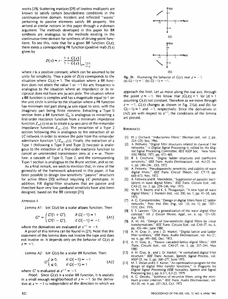
works [29]. Scattering matrices [29] of lossless multiports are known to satisfy certain boundedness conditions in the continuous-time domain. Incident and reflected “waves” pertaining to passive elements satisfy BR property. We arrived at similar notions in this paper through a z-domain argument. The methods developed in this paper for BR synthesis are analogous to the methods existing in the continuous-time domain for synthesis of driving-point func- tions. To see this, note that for a given BR function G(z), there exists a corresponding PR function (positive real) Z(s) given by
Z ( S ) = r -
1 - 5
where r is a positive constant, which can be assumed to be unity for simplicity. Thus a pole of Z(s) corresponds to the situation where G(z) = 1. The situation where a BR func- tion does not attain the value 1 or -1 for any frequency is analogous to the situation where an impedance or its re- ciprocal does not have anyjw axis pole. The situation where a BR function is complex and has a magnitude equal to 1 on the unit circle is similar to the situation where a PR function has minimum real part along io axis equal to zero, with the imaginary part being finite nonzero. Extracting a Type 0 section from a BR function C,,, is analogous to extracting a first-order reactance function from a minimum impedance function Z,( s) so as to create a jo-axis zero of the remainder impedance function Zm-l(s). The extraction of a Type 2 section following this is analogous to the extraction of an LC network in order to remove the pole from the remainder admittance function l/Z,,,-l(s). Finally, the extraction of a Type 1 (following a Type 0 and Type 2) two-pair is analo- gous to the extraction of a first-order reactance function to cancel an unintended transmission zero at s = 00. There- fore, a cascade of Type 0, Type 2, and the corresponding Type-I section is analogous to the Brune section, and so on.
As a final remark, we wish to mention that, in view of the generality of the framework advanced in this paper, it has been possible to design low-sensitivity “passive” structures for active filters [30] without requiring LC prototypes. In addition, FIR digital-filter structures that are passive and therefore have very low passband sensitivity have also been designed, based on the BR concept [31].
APPENDIX I
Lemma AI: Let G(z) be a scalar allpass function. Then
G”= C(l + C), if G(-I) = 1
C(I - C), if G(-I) = -I (AI)
where the derivatives are evaluated at z-’ = -1. A proof of this lemma can be found in [21]. Note that the
statement of this lemma does not involve the type and does not involve rn. It depends only on the behavior of C(z) at z = -1.
Lemma AZ: Let G(z) be a scalar BR function. Then
4 3 0, if C ( - I ) = -1 < 0, if C ( - I ) =I (A21
where C is evaluated at z-’ = - 1. proof: Since G(z) is a scalar BR function, it is analytic
in a small enough neighborhood of z = -1. SO the deriva- tive at z = -1 is independent of the direction in which we
T G I z l
t ’
(b) Fig. 21. Illustrating the behavior of C(z) near z = -1. (a) C(-I) = 1. (b) C(-1) = -1.
approach the limit. Let us move along the real axis, through the point z = -1. We know that IC(z)l c 1 for IzI > 1 assuming C(z) not constant. Therefore as we move through z = -1, G(z) changes as shown in Fig. 21(a) and (b) for C( -1) = 1 and -1, respectively. Since the derivatives in (A2) are with respect to z-’, the conditions of the lemma are proved.
REFERENCES
H. J. Orchard, “lnductorless filters,” Flectron Lett., vol. 2, pp.
A. Fettweis, “Digital filter structures related to classical filter networks,” in Digital Signal Processing / I , edited by the Dig- ital Signal Processing Committee, IEEE ASSP SOC. New York:
R. E. Crochiere, “Digital ladder structures and coefficient
4, pp. 240-246., Oct. 1972. sensitivity,” / €€E Trans. Audio Flectroacoust., vol. AU-20, no.
A. Fettweis, ”Pseudopassivity, sensitivity, and stability of wave digital filters,” /€E€ Trans. Circuit Theory, vol. CT-19, pp.
A. Fettweis and K. MeerkBtter, “Suppression of parasitic oscil- lations in wave digital filters,” / € € E Trans. Circuits Syst., vol. CAS-22, no. 3, pp. 239-246, Mar. 1975. M. N. S. Swamy and K. S. Thyagarajan, “A new type of wave digital filters,” /. Franklin Inst., vol. 300, no. 1, pp. 41-58, July 1975. A. G. Constantinides, ”Design of digital filters from LC ladder
1312, Dec. 1976. networks,” Proc. Inst. Flec. fng., vol. 123, no. 12. pp. 1307-
S. S. Lawson, “On a generalization of the wave digital filter concept,” Int. /. Circuit Theory, Appl., vol. 6, pp. 107-120, Apr. 1978. A. M. Ali, “Design of low-sensitivity digital filters by linear transformations,” /E€€ Trans. Circuits Syst., vol. CAS-27, no. 6, pp. 435-444, June 1980. A. H. Gray, Jr., and J. D. Markel, “Digital lattice and ladder filter synthesis,” /€E€ Trans. Audio Flectroacoust., vol. AU-21, no. 6, pp. 491-500, Dec. 1973. A. H. Gray, Jr., “Passive cascaded lattice digital filters,’‘ /E€€ Trans. Circuits Syst., vol. CAS-27, no. 5, pp. 337-344, May 1980. A. H. Gray, Jr., and J. D. Markel, “A normalized digital filter structure,” K E F Trans. ACOUS~., Speech, Signal Process., vol. ASSP-23, no. 3, pp. 268-277, June 1975. M. T. Dolan and I . F. Kaiser, “An optimization program for the design of digital filter transfer functions,” in Programs for Digital Signal Processing (IEEE Acoustics, Speech and Signal Processing Soc.), pp. 6.3-1, 6.3-23, 1979. A. G. Deczky, “Synthesis of recursive filters using the mini- mum p-error criterion,” /€€€ Trans. Audio Flectroacoust., vol. AU-20, no. 4, pp. 257-263, Oct. 1972.
224-225, Sep. 1966
IEEE PRESS, 1975, pp. 475-485.
668-673, NOV. 1972.
422 PROCEEDINGS OF THE IEEE. VOL. 72, NO 4. APRIL 1%
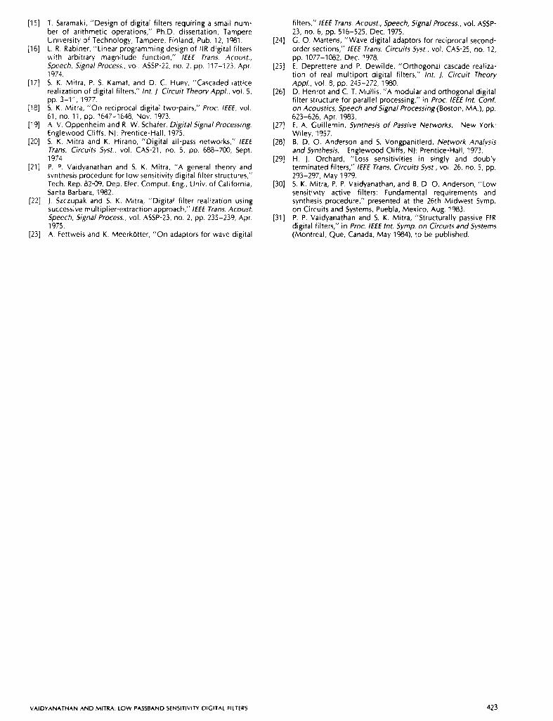
T. Saramaki, "Design of digital filters requiring a small num- ber of arithmetic operations," Ph.D. dissertation, Tampere University of Technology, Tampere, Finland, Pub. 12, 1981. L. R. Rabiner. "Linear programming design of IIR digital filters with arbitrary magnitude function," I€€€ Trans. Acoust., Speech, Signal Process., vol. ASSP-22. no. 2, pp. 117-123, Apr. 1974. S. K . Mitra, P. S. Kamat, and D. C. Huey, "Cascaded lattice realization of digital filters,'' Int. J , Circuit Theory Appl.. vol. 5.
S. K . Mitra, "On reciprocal digital two-pairs,'' Proc. /€€E. vol. 61, no. 11, pp. 1647-1648, Nov. 1973. A. V. Oppenheim and R. W. Schafer, Digital Signal Processing. Englewood Cliffs, NJ: Prentice-Hall, 1975. S. K . Mitra and K. Hirano, "Digital all-pass networks," / € € E Trans. Circuits Syst., vol. CAS-21, no. 5, pp. 688-700, Sept. 1974. P. P. Vaidyanathan and S. K. Mitra, "A general theory and synthesis procedure for low sensitivity digital filter structures," Tech. Rep. 82-09, Dep. Elec. Comput. Eng., Univ. of California, Santa Barbara, 1982. I . Szczupak and S. K . Mitra, "Digital filter realization using successive multiplier-extraction approach," / € E € Trans. Acoust.
1975. Speech, Signal Process., vol. ASSP-23, no. 2, pp. 235-239, Apr.
pp. 3-1 1, 1977.
[23] A. Fettweis and K. Meerkbtter, "On adaptors for wave digital
filters," / € € E Trans. Acoust., Speech, Signal Process., vol. ASSP- 23, no. 6, pp. 516-525, Dec. 1975. G. 0. Martens, "Wave digital adaptors for reciprocal second- order sections," /€€€ Trans. Circuits Syst., vol. CAS-25, no. 12, pp. 1077-1082, Dec. 1978. E. Deprettere and P. Dewilde, "Orthogonal cascade realiza- tion of real multiport digital filters,'' Int. 1. Circuit Theory
D. Henrot and C. T. Mullis, "A modular and orthogonal digital filter structure for parallel processing," in Proc. / € E € Int. Conf. on Acoustics, Speech and Signal Processing (Boston, MA.), pp. 623-626, Apr. 1983, E. A. Guillemin, Synthesis of Passive Networks. New York: Wiley, 1957. B. D. 0. Anderson and 5. Vongpanitlerd, Network Andpis and Synthesis. Englewood Cliffs, N): Prentice-Hall, 1973. H. I . Orchard, "Loss sensitivities in singly and doubly terminated filters," / E € € Trans. Circuits Syst., vol. 26, no. 5 , pp.
S. K. Mitra, P. P. Vaidyanathan, and B. D. 0. Anderson, "Low sensitivity active filters: fundamental requirements and synthesis procedure," presented at the 26th Midwest Symp. on Circuits and Systems, Puebla, Mexico, Aug. 1983. P. P. Vaidyanathan and S. K. Mitra, "Structurally passive FIR digital filters," in Proc. /E€€ Int. Symp. on Circuits andsystems (Montreal, Que, Canada, May I%), to be published.
Appl., VOI. 8, pp. 245-272, 1980.
293-297, May 1979.
VAIDYANATHAN AND MITRA: LOW PASSBAND SENSITIVITY DIGITAL FILTERS 423