Low P rof ile A ir G ri ppe r Series MHF2 - SMC ETech · Low P rof ile A ir G rippe r Series MHF2...
32
Low profile air gripper with space-saving design is newly released. Series MHF2 Low Profile Air Gripper 5-77
Transcript of Low P rof ile A ir G ri ppe r Series MHF2 - SMC ETech · Low P rof ile A ir G rippe r Series MHF2...

Low profile air gripper with space-saving design is newly released.
Series MHF2 Low Profile Air Gripper
5-77

The low profile design saves space and reduces bending moments.
Improved accuracy with smoothoperation
� Reduced bending moment and vibration
Height is approximately 1/3 the size of an equivalent Series MHZ2.
Stroke selection is available.3 standard stroke lengths are available for each bore size.Stroke can be selected to suit the work piece.
Low Profile Air Gripper
Series MHF2
Bore size
8
12
16
20
Height
19
25
33
41
(mm)MHZ2-20D3
MHF2-12D
Short
ø8
8
ø12
12
ø16
16
ø20
20
Medium 16 24 32 40
Long 32 48 64 80
mm mm mm mm
mm mm mm mm
mm mm mm mm
52
50
42
25
72.8
Low profile
design
��������
5-78

Improved mounting repeatabilityWith positioning pin holes
With positioning pin holes
Auto switches can be mounted on both sides.
Mounting is possible
from 4 directions.
Linear guide provides:High precision and high rigidity with martensitic stainless steel
Piping is available from 2 directionsPiping port position can be specified using a part number.
Axial piping
Centralized wiring and piping are possible.
Side piping
Easy positioning for mounting attachments
High degree of mounting flexibilityAs no brackets are required, mounting height can be minimized.
Strong holding forceDouble piston construction achieves compact design with strong holding force.
q
q
w
w
w
e
e
r
r
Model Bore size Holding force (N)
MHF2-8D�MHZ2-10D�
8
10
19
11
MHF2-12D�MHZ2-20D�
12
20
48
42
MHF2-16D�MHZ2-25D�
16
25
90
65
MHF2-20D�MHZ2-32D�
20
32
141
158
5-79

38
30
70
50
30
10
8060
60
40
20
40200
0.2MPa
0.6MPa
0.5MPa
0.4MPa
0.3MPa
Pressure 0.7MPa
Holding point L mm
Hol
ding
forc
e N
Model Selection
MHF2-12D�Model selection criteria with respect to work piece weight
Example
When it is desired to set the gripping force at 20 times or more the work piece weight.
Required griping force = 0.15 kg x 20 x 9.8 m/s2 = Approx. 29.4N or more
Work piece weight: 0.15kg
Length of gripping point : 30mm
Operating pressure : 0.4MPa
Confirmation of conditions Calculation of required gripping force Model selection from gripping force graph
Example
Gripping method: External gripping
Selection procedure
Confirmation of gripping force
Confirm gripping force Confirm external force on fingersConfirm gripping pointStep 1 Step 2 Step 3
Step 1
When gripping a work piece as in the
figure to the left and with the following
definitions,
F : Gripping force (N)
� : Coefficient of friction between
attachments and work piece
m : Work piece mass (kg)
g : Gravitational acceleration (= 9.8m/s2)
mg : Work piece weight (N)
the conditions under which the work
piece will not drop are
2�F � mg
and therefore,
mgF � 2 x �With "a" as the safety margin, F is
determined as follows:
mgF = x a 2 x �
Number of fingers
When � = 0.2 When � = 0.1
mgF = x 4 2 x 0.2
= 10 x mg
mgF = x 4 2 x 0.1
= 20 x mg
10 x work piece weight 20 x work piece weight
(Note) � Even in cases where the coefficient of friction is greater than � = 0.2, for safety reasons, SMC recommends selecting a gripping force
which is at least 10 to 20 times the work piece weight.
� If is necessary to allow a greater safety margin for high accelerations and strong impacts, etc.
mgμF μF
F F
� Although differences will exist depending on factors such as
shape and the coefficient of friction between attachments and
work pieces, select a model which will provide a gripping force
10 to 20 times the weight of the work piece.
(Note1) Refer to the model selection illustration for more
information.� Furthermore, in cases with high acceleration or impact, etc., it
is necessary to allow an even greater margin of safety.
Selecting the MHF2-12D�The gripping force is obtained from
the intersection point of the gripping point distance L=30mm and a pressure of 0.4MPa.Gripping force N=38N
�A gripping force of 38N satisfies the required gripping force of 29.4N. Therefore, the selection of MHF2-12D is appropriate.
Gripping force at least 10 to 20 times the work piece weightThe "10 to 20 times or more of the work piece weight" recommended by
SMC is calculated with the safety margin of a = 4, which allows for
impacts that occur during normal transportation, etc.
Model selection illustration
Series MHF2Model Selection
5-80

Effective gripping force: Series MHF2Step 1
External gripping Internal gripping
F F
L L
�Expressing the effective grip-
ping force
The effective gripping force
shown in the graphs to the right
is expressed as F, which is the
thrust of one finger when both
fingers and attachments are in
full contact with the work piece
as shown in the figure below.
806040
210
150
90
30
100
Gripping point L mm
180
120
60
20
Grippin
g forc
e N
0
80
70
50
30
10
60
Gripping point L mm
60
40
20
4020
Grippin
g forc
e N
0
140
100
60
20
100
Gripping point L mm
120
80
40
80604020
Grippin
g forc
e N
0
Gripping point L mm
30
20
10
40302010
Grippin
g forc
e N
0
MHF2-8D�
MHF2-16D�
MHF2-12D�
MHF2-20D�
Pressure 0.7MPa
0.6MPa
0.5MPa
0.4MPa
0.3MPa
0.2MPa
Pressure 0.7MPa
0.6MPa
0.5MPa
0.4MPa
0.3MPa
0.2MPa
Pressure 0.7MPa
0.6MPa
0.5MPa
0.4MPa
0.3MPa
0.2MPa
Pressure 0.7MPa
0.6MPa
0.5MPa
0.4MPa
0.3MPa
0.2MPa
Series MHF2
5-81

5-82
Effective gripping force: Series MHF2Step 2
External gripping Internal gripping
Model Selection
L
HHolding point
H
L
Holding point
�The air gripper should be operated so that
the amount of overhang "H" will stay within
the range given in the graphs below.�If the work piece gripping point goes beyond
the range limits, this will have an adverse
effect on the life of the air gripper.
MHF2-8D�
MHF2-16D�
MHF2-12D�
MHF2-20D�
Pressure 0.2M
Pa
100
80
60
100
0.5MPa
0.6MPa
0.7MPa
0.4MPa
0.3MPa
40
20
806040200
Ove
rha
ng
H
mm
Gripping point L mm
Pressure 0.2M
Pa
100
80
60
100
0.5MPa
0.6MPa
0.7MPa
0.4MPa
0.3MPa
40
20
80604020
Ove
rha
ng
H
mm
Gripping point L mm
0
80
80
60 0.5MPa
0.6MPa
0.7MPa
0.4MPa
0.3MPa
Pressure 0.2M
Pa40
20
604020
Ove
rha
ng
H
mm
Gripping point L mm
0
30
10
50
503010
0.5MPa
0.6MPa
0.7MPa
0.4MPa
0.3MPa
Pressure 0.2M
Pa
40
20
4020
Ove
rha
ng
H
mm
Gripping point L mm
0
Series MHF2
5-82

5-83
Confirmation of external force on fingers: Series MHF2
Model
MHF2-8D�
MHF2-12D�
MHF2-16D�
MHF2-20D�
58
98
176
294
0.26
0.68
1.4
2
0.26
0.68
1.4
2
0.53
1.4
2.8
4
Allowable vertical load
Fv (N)
Maximum allowable moment
Pitch moment
Mp (N�m)
Yaw moment
My(N�m)
Roll moment
Mr (N�m)
L: Distance to the point at which the load is applied (mm)
Calculation of allowable external force
(when moment load is applied)Calculation example
M(Maximum allowable moment)(N�m)Allowable load F(N) = L x 10-3
�
(�Unit converted invariable number)
0 . 6 8Allowable load F = 30 x 10-3
= 22.7 (N)
Load f = 10 (N) � 22.7 (N)
Note) The load and moment values in the table indicate static values.
Fv My
L
Mp
L
Mr
L
When a load off = 10N is operating, which applies
pitch moment to point L = 30 mm from the end of
the MHF2-12D finger.
Therefore, it can be used.
Step 3
Series MHF2
5-83
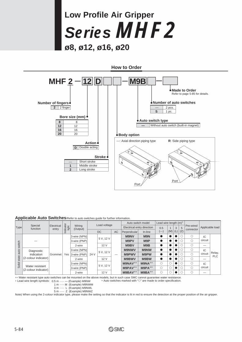
Low Profile Air Gripper
Se ries MHF2ø8, ø12, ø16, ø20
Number of fingers2 2 finger
Bore size (mm) 8121620
8121620
—
—: Axial direction piping type R: Side piping type
Without auto switch (built-in magnet)Auto switch type
ActionD
Body option
Stroke
MHF 2 12 M9BDHow to Order
Double acting
—S
2 pcs.1 pc.
Number of auto switches
—12
Short strokeMiddle strokeLong stroke
PortPort
�
�
�
�
�
�
�
�
�
�
�
�
�
�
�
�
�
�
�
�
�
�
�
�
�
�
�
�
�
�
�
�
�
�
�
�
�
�
�
�
�
�
�
�
�
Made to OrderRefer to page 5-85 for details.
Applicable Auto Switches/Refer to auto switches guide for further information.
Type
Solid
sta
te a
uto
switc
h
Special function
Electrical entry
Wiring (Output)
Lead wire length (m)∗Auto switch modelElectrical entry direction
Load voltage
DC AC Perpendicular In-lineApplicable loadPre-wired
connector5(Z)
Diagnostic indication
(2-colour indicator)
Water resistant(2-colour indicator)
Grommet Yes
3-wire (NPN)3-wire (PNP)
2-wire3-wire (NPN)3-wire (PNP)
2-wire3-wire (NPN)3-wire (PNP)
2-wire
—24 V
5 V, 12 V
12 V
5 V, 12 V
12 V
5 V, 12 V
12 V—
Relay, PLC
—
—
ICcircuit
ICcircuit
—
ICcircuit
3(L)
1(M)
0.5(—)
M9N
M9P
M9B
M9NW
M9PW
M9BW
M9NA∗∗
M9PA∗∗
M9BA∗∗
M9NV
M9PV
M9BV
M9NWV
M9PWV
M9BWV
M9NAV∗∗
M9PAV∗∗
M9BAV∗∗
∗∗ Water resistant type auto switches can be mounted on the above models, but in such case SMC cannot guarantee water resistance.∗ Lead wire length symbols: ∗ Auto switches marked with “�” are made to order specification.
Note) When using the 2-colour indicator type, please make the setting so that the indicator is lit in red to ensure the detection at the proper position of the air gripper.
0.5 m ······ — (Example) M9NW 1 m ······ M (Example) M9NWM 3 m ······ L (Example) M9NWL 5 m ······ Z (Example) M9NWZ
Indi
cato
r lig
ht
5-84

5-85
Made to Order
Symbol Specifications/DescriptionHeat resistance (100°C)Fluororubber sealWithout magnetEPDM seal/Fluorine greaseFluorine greaseGrease for food processing machines, Fluorine greaseGrease for food processing machinesAnti-corrosive treatment of fingerAnti-corrosive treatment of finger, guide and jointWith an adjustable opening/closing finger positioning
-X4
-X5
-X50
-X53
-X63
-X79
-X79A
-X81A
-X81B
-X83
Symbol
Double acting:Internal grip
Double acting:External grip
MoistureControl TubeSeries IDK
Made to Order: Individual Specifications
Symbol Specifications/DescriptionWith an adjustable opening/closing finger positioning-X83
When operating an actuator with a small diameter
and a short stroke at a high frequency, the dew
condensation (water droplet) may occur inside the
piping depending on the conditions.
Simply connecting the moisture control tube to the
actuator will prevent dew condensation from oc-
curring. For details, refer to the IDK series in the
Best Pneumatics No. 6.
Ambient and fluid temperatureRepeatabilityMaximumoperatingfrequencyLubricationActionAuto switch (Optional) Note2)
SpecificationsAir
ø8: 0.15 to 0.7 MPaø12 to 20: 0.1 to 0.7 MPa
�10 to 60�C (with no condensation)�0.05 mm
120 c.p.m.120 c.p.m.60 c.p.m.
Not requiredDouble acting
Solid state switch (3-wire, 2-wire)
Operating pressure
Short strokeMiddle strokeLong stroke
Fluid
Model
Action Model
Gripping forceCylinder
bore(mm)
Unobstructed capacity
(cm3)
Fingeropen side
Fingerclose side
MHF2-8DMHF2-8D1MHF2-8D2MHF2-12DMHF2-12D1MHF2-12D2MHF2-16DMHF2-16D1MHF2-16D2MHF2-20DMHF2-20D1MHF2-20D2
8
12
16
20
Opening/closing stroke
(Both sides)mm
81632122448163264204080
Note2)
Weightg
6585
120155190275350445650645850
1,225
0.71.12.01.93.36.14.98.2
14.98.7
15.128.0
0.61.01.91.63.05.84.17.4
14.07.3
13.726.6
19
48
90
141
Double acting
Note 1) At the pressure of 0.5 MPa, when holding point L is 20 mm.Note 2) Excluding the auto switch weight
Effective holding force per finger N
Note 1) This is the value when no offset load is applied to the finger.When an offset load is applied to the finger, the maximum value is �0.15 mm due to the influence of backlash of the rack and pinion.
Note 2) Refer to page 6-15 for further information on auto switch specifications.
Note1)
Note1)
Low Profile Air Gripper Series MHF2
5-85

Series MHF2
5-86
Replacement part/Grease pack part no.:
Guide unit: GR-S-010 (10 g) Cylinder unit: GR-L-005 (5 g)
Construction
MHF2-8D, MHF2-8D1
MHF2-8D2
Parts listNo. Description
BodyPistonJointGuide railFinger Roller stopperPinionCap ACap BCap C
MaterialAluminium alloyStainless steelStainless steelStainless steelStainless steelStainless steelCarbon steel
Aluminium alloyAluminium alloyAluminium alloy
NoteHard anodized
Heat treatmentHeat treatmentHeat treatment
Nit ridingClear anodizedClear anodizedClear anodized
12345678910
Parts listNo. Description
Head damperClipRackMagnetSteel ballsWear ringRollerNeedle rollerParallel pinPiston sealGasket
MaterialUrethane rubber
Stainless steel wireStainless steel
Rare earth magnetHigh carbon chromium bearing steel
Synthetic resinHigh carbon chromium bearing steelHigh carbon chromium bearing steel
Stainless steelNBRNBR
Note
Nit ridingNickel plated
1112131415161718192021
o
!1 !2
i
q
rt !5 y!9
w
e
u !0!3
!6
!7
!8 !4 @0 @1
Replaceable parts list
MHF2-8DMHF8-PSMHF-A0802
MHF2-8D1MHF8-PSMHF-A0802-1
MHF2-8D2MHF8-PS-2MHF-A0802-2
Seal kitFinger assembly
12, 20, 213, 4, 5, 6, 15, 17, 19 Mounting screw
Bolts for body through hole mountingPart No.
MHF2-8DMHF2-8D1MHF2-8D2
2 pieces/unit2 pieces/unit4 pieces/unit
ContentsKit No.
MHF-B08
Number of piecesDescription
The bolts for body through hole mounting are attached to the product. They are also provided at an order of 1 piece or more with the above part

Parts list
No. Description
Body
Piston
Joint
Guide rail
Finger
Roller stopper
Pinion
Cap A
Cap B
Cap C
Head damper
Rack
Material
Aluminium alloy
Aluminium alloy
Stainless steel
Stainless steel
Stainless steel
Stainless steel
Carbon steel
Aluminium alloy
Aluminium alloy
Aluminium alloy
Urethane rubber
Stainless steel
Note
Hard anodized
Clear anodized
Heat treatment
Heat treatment
Heat treatment
Nit riding
Clear anodized
Clear anodized
Clear anodized
Nit riding
1
2
3
4
5
6
7
8
9
10
11
12
Parts list
No. Description
Magnet
Steel balls
Wear ring
ø12: Roller
ø16 to 20: Parallel pin
Needle roller
ø12: R shape snap ring
ø16 to 20: C type snap ring
Parallel pin
Piston seal
Gasket
Gasket
Material
Tare earth magnet
High carbon chromium bearing steel
Synthetic resin
High carbon chromium bearing steel
Stainless steel
High carbon chromium bearing steel
Carbon steel
Stainless steel
NBR
NBR
NBR
Note
Nickel plated
Nickel plated
13
14
15
16
17
18
19
20
21
22
u
!2
w
o
!4 rt
!5
y!9
i q!3
e
!0@2
!6
!1
!7
!8
@0
@1
MHF2-12D� to 20D�
Replaceable parts list
MHF2-12D
MHF12-PS
MHF-A1202
MHF2-12D1
MHF12-PS
MHF-A1202-1
MHF2-12D2
MHF12-PS
MHF-A1202-2
Seal kit
Finger assembly
Seal kit
Finger assembly
Seal kit
Finger assembly
20, 21, 22
3, 4, 5, 6, 14, 16,19 Mounting screw
MHF2-16D
MHF16-PS
MHF-A1602
MHF2-16D1
MHF16-PS
MHF-A1602-1
MHF2-16D2
MHF16-PS
MHF-A1602-2
20, 21, 22
3, 4, 5, 6, 14, 16,19 Mounting screw
MHF2-20D
MHF20-PS
MHF-A2002
MHF2-20D1
MHF20-PS
MHF-A2002-1
MHF2-20D2
MHF20-PS
MHF-A2002-2
20, 21, 22
3, 4, 5, 6, 14, 16,19 Mounting screw
Bolts for body through hole mounting
Part No.
MHF2-12D
MHF2-12D1
MHF2-12D2
2 pieces/unit
2 pieces/unit
4 pieces/unit
Number of pieces
MHF-B12
DescriptionKit No.
Kit No.
Kit No.
Contents
Description Contents
Description Contents
�The bolts for body through hole mounting are attached to the product. They are also provided at an order of 1 piece or more with the above part numbers.
�When mounting MHF2-16D� or MHF2-20D� with the body through holes, use hexagon socket
head screws available on the market.
Construction
Low Profile Air Gripper Series MHF2
5-87

Dimensions
MHF2-8D Scale: 80%
2-ø4.5
2-ø2.6 through (Mounting hole)�
11
E-E
26
14
12
10
6
10
6
2-ø2H9+0.025 0 depth 2
4-M2.5 thread depth 3
4-M3 thread depth 4
Mounting thread
Mounting thread
Attachment mounting thread
Accessory option:
Hexagon socket head screw (special screws)
1.3
Groove for
auto switch mounting
ø4
3
3
Groove for auto switch mounting
3 28.3 3.4
16
2.5
H9
+0.0
25
0
depth
2.5
ø2.5H9+0.025 0 depth 2.5
2-M3 thread depth 7
Mounting thread
Mounting thread
14
15.8
5.9
19
17
32
Finger closing port
M3
Finger opening port
M3 0-0.1
+0.1 0
0.8 0.8
Close: 0
Open: 8�1
22
11
36
12 12
2-M3 thread depth 4
E
E
ø4
15
M2.5 x 0.45
11
22
2-M3 thread depth 4
�Use the attached hexagon socket head
screws for mounting holes.
Series MHF2
5-88

Dimensions
MHF2-8D1 Scale: 80%
Accessory option:
Hexagon socket head screw (special screws)
2-ø4.5
2-ø2.6 through (mounting hole)�
11
E-E
26
26
12
11
7
11
72-ø2H9
+0.025 0 depth 2
4-M2.5 thread depth 3
Attachment mounting thread
4-M3 thread depth 4
Mounting thread
Mounting thread
Groove for auto switch mounting
1.3
ø4
3
3
34
11
2-M3 thread depth 4
ø4
15
M2.5 x 0.45
14
15.8
5.9
19
17
32
Finger closing port
M3
Finger opening port
M3
0-0.1
3.440.33
28
2.5
H9
+0.0
25
0
depth
2.5
ø2.5H9+0.025 0 depth 2.5
2-M3 thread depth 7
Mounting thread
0.8
Open: 16�1
34
11
48
14
0.8
14
2-M3 thread depth 4
E
E
Close: 0+0.1 0
Mounting thread
�Use the attached hexagon socket head
screws for mounting holes.
Groove for
auto switch mounting
Low Profile Air Gripper Series MHF2
5-89
Dimensions
MHF2-8D2 Scale: 80%
4-ø4.5
4-ø2.6 through
(mounting hole)�
11
E-E
Groove for auto switch mounting
ø4
3
3
1.3
ø4
15
M2.5 x 0.45
14
15.8
5.9
19
17
32
Finger closing port
M3
Finger opening port
M3
0-0.1
3.464.3
171717
2.5
H9
+0.0
25
0
depth
2.5
3
ø2.5H9+0.025 0 depth 2.5
4-M3 thread depth 7
0.8
Open: 32�1
Close: 0
18 0.8 18
58
11
72 2-M3 thread depth 4
Mounting thread
E
E
+0.1 0
12 26
8 5 85
50
2-ø2H9+0.025 0 depth 2
8-M2.5 thread depth 3
Attachment mounting thread
4-M3 thread depth 4
Mounting thread
Mounting thread
58
11
2-M3 thread depth 4
Mounting thread
�Use the attached hexagon socket head
screws for mounting holes.
Groove for
auto switch mounting
Accessory option:
Hexagon socket head screw (special screws)
Series MHF2
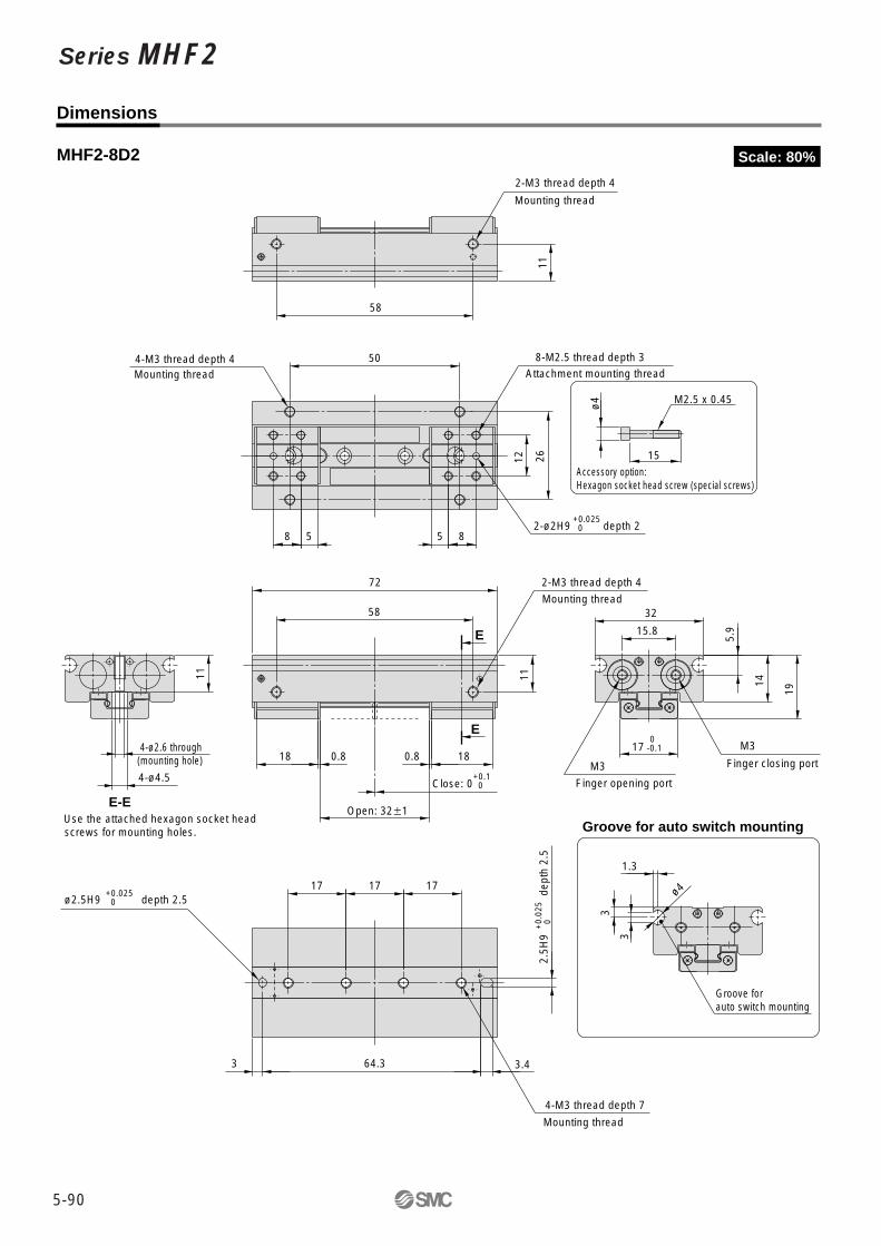
5-90

Dimensions
MHF2-12D Scale: 65%
Groove for
auto switch mounting
2-ø5.5
2-ø3.4 through
(mounting hole)�
14
.8
E-E
7.7
20
19
20
40
25
M5
Finger opening port
M5
Finger closing port
14
9
14
9
15
28
33
4-M3 thread depth 4
2-ø2.5H9+0.025 0 depth 2.5
4-M4 thread depth 5
Mounting thread
Mounting thread
Attachment mounting thread
Groove for auto switch mounting
ø4
3.3
3
1.7
0-0.1
+0.1 0
ø5
20
M3
42
3H
9+
0.0
25
0
depth
3
4
26
4
ø3H9+0.030 0 depth 3
2-M4 thread depth 10
1
Open: 12�1
Close: 0
38
15
52
18
1
18
2-M4 x 0.7 thread depth 5
Mounting thread
Mounting thread
E
E
38
15
2-M4 thread depth 5
�Use the attached hexagon socket head
screws for mounting holes.
Accessory option:
Hexagon socket head screw (special screws)
Low Profile Air Gripper Series MHF2
5-91

Dimensions
MHF2-12D1 Scale: 65%
Groove for
auto switch mounting
0-0.1
2-ø5.5
2-ø3.4 through (mounting hole)�
14
.8
E-E
7.7
20
19
20
40
25
Finger opening port
M5
M5
Finger closing port
Groove for auto switch mounting
ø4
3.3
3
1.7
ø5
20
M3
58
3H
9+
0.0
25
0
depth
3
4
42
4
ø3H9+0.030 0 depth 3
2-M4 thread depth 10
Mounting thread
1
Open: 24�1
Close: 0
54
15
68
21 1 21
2-M4 thread depth 5
Mounting thread
E
E
+0.1 0
12 4.5 124.5
15
44
33
8-M3 thread depth 4
Attachment mounting thread
2-ø2.5H9+0.025 0 depth 2.5
4-M4 thread depth 5
Mounting thread
54
15
2-M4 thread depth 5
Mounting thread
�Use the attached hexagon socket head
screws for mounting holes.
Accessory option:
Hexagon socket head screw (special screws)
Series MHF2
5-92
Dimensions
MHF2-12D2 Scale: 65%
4-ø5.5
4-ø3.4 through (mounting hole)�
14
.8
E-E
18 4.5 184.5
15
80
33
8-M3 thread depth 4
Attachment mounting thread
2-ø2.5H9+0.025 0 depth 2.5
4-M4 thread depth 5
Mounting thread
Groove for auto switch mounting
ø4
3.3
3
1.7
ø5
20
M3
7.7
20
19
20
40
25
Finger opening port
M5
M5
Finger closing port
0-0.1
262626
94
3H
9+
0.0
25
0
depth
3
44
ø3H9+0.025 0 depth 3
4-M4 thread depth 10
Mounting thread
1
Open: 48�1
Close: 0
90
15
104
27 1 27
2-M4 thread depth 5
Mounting thread
E
E
+0.1 0
90
15
2-M4 thread depth 5
Mounting thread
�Use the attached hexagon socket head
screws for mounting holes.
Groove for
auto switch mounting
Accessory option:
Hexagon socket head screw (special screws)
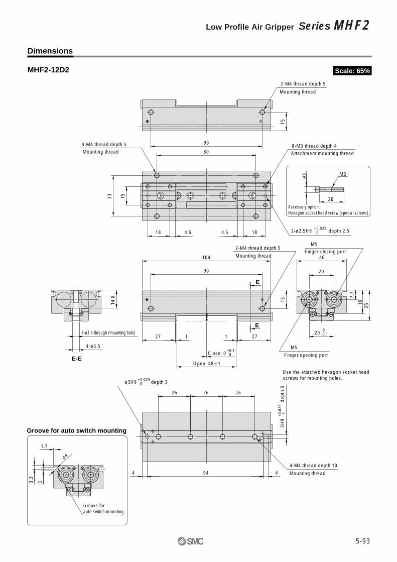
Low Profile Air Gripper Series MHF2
5-93

Dimensions
MHF2-16D Scale: 50%
38
4H
9+
0.0
30
0
depth
3
6 57.5 5
ø4H9+0.030 0 depth 3
2-M5 thread depth 12
Mounting thread
2-ø7.5
2-ø4.3 through (mounting hole)
20
E-E
1.2
Open: 16�1
Close: 0
20
52
72
25
1.2
25
2-M5 thread depth 5.5
Mounting thread
20
15 5 155
36
43
2-ø3H9+0.025 0 depth 3
8-M4 thread depth 4
Attachment mounting thread
Mounting thread
4-M5 thread depth 5.5
20
52
2-M5 thread depth 5.5
Mounting thread
Groove for auto switch mounting
ø4
2.2
4.6 3
E
E
26
10
.6
24
27
50
33
Finger closing port
Finger opening port
M5
M5 x 0.8
0 -0.1
+0.1 0
Groove for
auto switch mounting
Series MHF2
5-94
Dimensions
MHF2-16D1 Scale: 50%
26
10
.6
24
27
50
33
Finger closing port
Finger opening port
M5
M5
60
4H
9+
0.0
30
0
depth
3
6 79.5 5
ø4H9+0.030 0 depth 3
2-M5 thread depth 12
Mounting thread
2-ø7.5
2-ø4.3 through
(mounting hole)
20
E-E
20
18 5.5 185.5
58
43
2-ø3H9+0.025 0 depth 3
8-M4 thread depth 4
Attachment mounting thread
4-M5 thread depth 5.5
Mounting thread
Groove for auto switch mounting
ø4
2.2
4.6 3
20
74
2-M5 thread depth 5.5
Mounting thread
0-0.1
1.2
Open: 32�1
Close: 0
20
74
94
29
2-M5 thread depth 5.5
1.2 29
E
E
+0.1 0
Mounting thread
Groove for
auto switch mounting
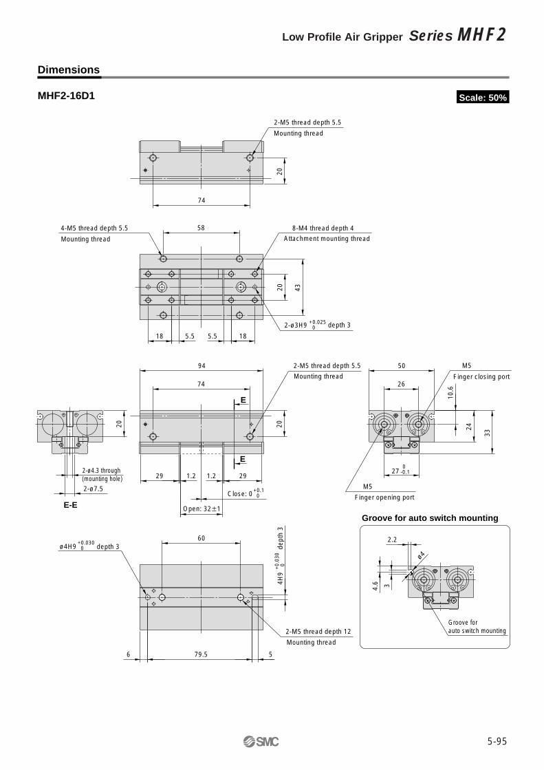
Low Profile Air Gripper Series MHF2
5-95

Dimensions
MHF2-16D2 Scale: 50%
4H
9+
0.0
30
0
depth
3
363636
6 127.5 5
ø4H9+0.030 0 depth 3
4-M5 thread depth 12
Mounting thread
4-ø7.5
4-ø4.3 through
(mounting hole)
20
E-E
20
26 5.5 265.5
106
43
2-ø3H9+0.025 0 depth 3
8-M4 thread depth 4
Attachment mounting thread
4-M5 thread depth 5.5
Mounting thread
20
122
2-M5 thread depth 5.5
Mounting thread
Groove for auto switch mounting
ø4
2.2
4.6 3
26
10
.6
24
27
50
33
Finger closing port
M5
M5
Finger opening port
0-0.1
1.2
Open: 64�1
Close: 0
20
122
142
37
2-M5 thread depth 5.5
Mounting thread
1.2 37
E
E
+0.1 0
Groove for
auto switch mounting
Series MHF2
5-96
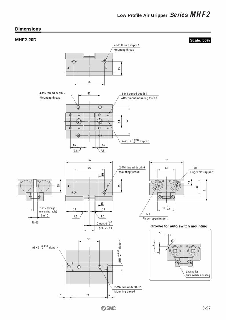
Dimensions
MHF2-20D Scale: 50%
E-E
2-ø10
2-ø5.2 through
(mounting hole)
25
24
16
7.5
16
7.5
40
52
2-ø3H9+0.025 0 depth 3
8-M4 thread depth 4
Attachment mounting thread
4-M6 thread depth 6
Mounting thread
Groove for auto switch mounting
ø4
2.3
6
3
+0.1 0
13
33
30
62
32
41
Finger opening port
M5
Finger closing port
M5
0-0.1
5H
9+
0.0
30
0
depth
4
38
6716
ø5H9+0.030 0 depth 4
2-M6 thread depth 15
Mounting thread
56
25
2-M6 thread depth 6
Mounting thread
1.2
Open: 20�1
Close: 0
56
25
86
31
1.2
31
2-M6 thread depth 6
E
EMounting thread
Groove for
auto switch mounting
Low Profile Air Gripper Series MHF2
5-97

Dimensions
MHF2-20D1 Scale: 50%
E-E
2-ø10
2-ø5.2 through
(mounting hole)
25
13
33
30
62
32
41
Finger opening port
M5
Finger closing port
M5
24
20 8 208
68
52
2-ø3H9+0.025 0
+0.1 0
0-0.1
depth 3
8-M4 thread depth 4
Attachment mounting thread
4-M6 thread depth 6
Mounting thread
Groove for auto switch mounting
ø4
2.3
6
3
5H
9+
0.0
30
0
depth
466
6996
ø5H9+0.030 0 depth 4
2-M6 thread depth 15
Mounting thread
1.2
Open: 40�1
Close: 0
84
25
114
36
2-M6 thread depth 6
Mounting thread
1.2 36
E
E
84
25
2-M6 thread depth 6
Mounting thread
Groove for
auto switch mounting
Series MHF2
5-98

Dimensions
MHF2-20D2 Scale: 50%
E-E
4-ø10
4-ø5.2 through
(mounting hole)
25
24
30 8 308
128
52
2-ø3H9+0.025 0 depth 3
8-M4 thread depth 4
Attachment mounting thread
Mounting thread
4-M6 thread depth 6
144
25
2-M6 thread depth 6
Mounting thread
Groove for auto switch mounting
ø4
2.3
6
3
13
33
30
62
324
1
Finger opening port
M5
Finger closing port
M5
0-0.1
1.2
Open: 80�1
144
25
174
46 1.2 46
2-M6 thread depth 6
Mounting thread
Close: 0
E
E
+0.1 0
4242 42
5H
9+
0.0
30
0
depth
4
615964-M6 thread depth 15
ø5H9+0.030 0 depth 4
Mounting thread
Groove for
auto switch mounting
Low Profile Air Gripper Series MHF2
5-99

5-100
∗
Series MHF2
Body Option: Side Piping Type
Body Option Dimension
A
7
10
B
61
76
66
C
11
23
D
M3MHF2-8D2R
MHF2-12DR
MHF2-12D1R
MHF2-12D2R
MHF2-16DR
MHF2-16D1R
MHF2-16D2R
MHF2-20DR
MHF2-20D1R
MHF2-20D2R
Body Option Dimension
A B
37
C
11
D
MHF2-8DR
MHF2-8D1R
MHF2-8DR
MHF2-8D1R
MHF2-8D2R
MHF2-12D�R
MHF2-16D�R
MHF2-20D�R
B A
C
D
(∗D
(∗
B
C
A
D
(∗D
(∗

Auto Switch Hysteresis
Auto Switch Mounting
MHF2-8D�
MHF2-12D�
MHF2-16D�
MHF2-20D�
0.5
0.5
0.5
0.5
0.5
0.5
0.5
0.5
1
1
1
1
D-M9�(V)D-M9�W(V)
Red ON Green ON
Strait bladed watch
makers screw driver
Auto switch
ø5 to ø6Switch installation screw
M2.5 x 4l
Hysteresis
Hysteresis
Auto switch operating position (OFF)
Auto switch operating position (ON)
Insert the auto switch into the switch mounting groove in the
air chuck in the direction shown below, and after setting the
mounting position, tighten the attached switch mounting screw
with a screwdriver.
Note) Use a screwdriver with a grip diameter of 5 to 6 mm to tighten the
auto switch mounting screw. The tightening torque should be about
0.05 to 0.1N⋅m. When you begin to feel that the screw is being
tightened, turn it further by 90.
Auto Switch Protrusion from the Body End Surface
�The amount of auto switch protrusion from the body end surface is
shown in the table below.
�Use this as a standard when mounting, etc.
MHF2-8D
MHF2-8D1
MHF2-8D2
MHF2-12D
MHF2-12D1
MHF2-12D2
MHF2-16D
MHF2-16D1
MHF2-16D2
MHF2-20D
MHF2-20D1
MHF2-20D2
Lead wire type
Illustration
Model
Open
Close
Open
Close
Open
Close
Open
Close
Open
Close
Open
Close
Open
Close
Open
Close
Open
Close
Open
Close
Open
Close
Open
Close
Auto sw
itch
In-line entry
D-M9� D-M9�W D-M9�V D-M9�WV
Perpendicular entry
6.5
6.5
6.5
6.5
0.5
0.5
3
3
1
1
�
�
�
�
�
�
�
�
�
�
�
�
�
�
6.5
6.5
6.5
6.5
0.5
0.5
3
3
1
1
�
�
�
�
�
�
�
�
�
�
�
�
�
�
4.5
4.5
4.5
4.5
�
�
1
1
�
�
�
�
�
�
�
�
�
�
�
�
�
�
�
�
4.5
4.5
4.5
4.5
�
�
1
1
�
�
�
�
�
�
�
�
�
�
�
�
�
�
�
�Note) There is no protrusion for sections of the table with no values entered.
Auto switch protrusion
L L
When using an auto
switch on the mounting
plate side, the switch will
protrude from the end
face as shown below.
Please provide a run off
apace of 2mm or deeper
on the mounting plate.
Caution
2m
m o
r m
ore
"Runoff"
Auto switches have hysteresis similar to micro switches. Use
the table below as a guide when adjusting auto switch
positions, etc.
Finger position
Low Profile Air Gripper Series MHF2
5-101

Detection
example
Detecting
position
Operation of
auto switch
Auto switch
mounting position
/setting procedure
Oneauto switch
Co
mb
ina
tio
n o
f d
ete
cti
on
Twoauto switches
q Confirmation of finger
reset position
w Confirmation of work
holding
e Confirmation of work
releasing
1) Detection of work (External holding)
Various auto switch applications are possible through different combinations of auto switch quantity and detecting positions.
Finger
fully open
position
Work
holding
position
Finger
fully closed
position
Switch ON at finger reset position
(Light: ON)
Switch ON at work holding position
(Light: ON)
At work holding position [Normal operation]
: Switch OFF (Light: OFF)
Work releasing condition [Abnormal operation]
: Switch ON (Light: ON)
�
�
�
�
�
�
�
Procedure 2)
Insert the auto switch mounting groove from
the direction shown in the figure.
Indicator lighting position
Fitting position
Fitting position
�Connect a
switch
applying no or
low voltage
and follow the
procedures for
setting.
0.3 to 0.5mm
0.3 to 0.5mm
Procedure 1)
Fully open the
fingers.
Procedure 1)
Locate the
fingers in the
work holding
position.
Procedure 1)
Locate the
fingers in the
fully closed
position.
Procedure 3) Slide auto switch in the
direction of the arrow until the indicator
light comes on.
Procedure 4) Slide the auto switch a
further distance in the direction of the
arrow until the indicator light goes out.
Procedure 3) Slide auto switch in the direction of the arrow until the indicator lights.
Move switch a further 0.3 to 0.5mm in the direction of the arrow and set.
Procedure 5) Move the auto switch in
the opposite direction, as shown by the
arrow, a distance of 0.3 to 0.5mm and
set.
Note) �It is recommended that work be held at the center of the finger stroke.
�If work is held around the end position of finger opening stroke, the above detecting combination may be limited due to the ON/OFF differential of the auto switches.
��
Series MHF2Installation and Setting of Auto Switch
5-102

Detection
example
Detecting
position
Operation of
auto switch
Auto switch
mounting position
/setting procedure
Oneauto switch
Co
mb
ina
tio
n o
f d
ete
cti
on
Twoauto switches
q Confirmation of finger
reset position
w Confirmation of work
holding
e Confirmation of work
releasing
2) Detection of work (Internal holding)
Various auto switch applications are possible through different combinations of auto switch quantity and detecting positions.
Note) �It is recommended that work be held at the center of the finger stroke.
�If work is held around the end position of finger opening stroke, the above detecting combination may be limited due to the ON/OFF differential of the auto switches.
Finger
fully closed
position
Work
holding
position
Finger
fully open
position
Switch ON at finger reset position
(Light: ON)
Switch ON at work holding position
(Light: ON)
At work holding position [Normal operation]
: Switch OFF (Light: OFF)
Work releasing condition [Abnormal operation]
: Switch ON (Light: ON)
Procedure 4) Slide the auto switch a further distance in the direction of the arrow
until the indicator light goes out.
Procedure 5) Move the auto switch in the opposite direction, as shown by the arrow,
a distance of 0.3 to 0.5mm and set.
Indicator lighting position
Indicator lighting position
Fitting position
Fitting position
�Connect a
switch
applying no or
low voltage
and follow the
procedures for
setting.
0.3 to 0.5mm
0.3 to 0.5mm
Procedure 2)
Insert the auto switch mounting groove from
the direction shown in the following drawing.
Procedure 3) Slide auto switch in the
direction of the arrow until the indicator
lights comes on.
Move switch a further 0.3 to 0.5mm in
the direction of the arrow and set.
Procedure 3) Slide auto switch in the direction of the arrow until the indicator lights.
Procedure 1)
Fully open the
fingers.
Procedure 1)
Locate the
fingers in the
work holding
position.
Procedure 1)
Locate the
fingers in the
fully closed
position.
�
�
�
�
��
�
��
Series MHF2Installation and Setting of Auto Switch
5-103

5-104
Series MHF2 Made to Order: Individual Specifications
With An Adjustable Opening/Closing Finger Positioning1
•Stroke can be adjusted to suit the workpiece•3 types of opening/closing finger stroke adjustments (Adjustable finger opening/closing position type, Adjustable finger opening position type, Adjustable finger closed position type)
Short Adjuster4 mm
Long Adjuster8 mm
Short Adjuster8 mm
Long Adjuster12 mm
Short Adjuster10 mm
Long Adjuster14 mm
Short Adjuster8 mm
Long Adjuster18 mm
8 mm
12 mm
16 mm
20 mm
Short Adjuster6 mm
Long Adjuster10 mm
Short Adjuster8 mm
Long Adjuster14 mm
Short Adjuster8 mm
Long Adjuster18 mm
Short Adjuster10 mm
Long Adjuster20 mm
16 mm
24 mm
32 mm
40 mm
Short Adjuster12 mm
Long Adjuster22 mm
Short Adjuster18 mm
Long Adjuster28 mm
Short Adjuster16 mm
Long Adjuster36 mm
Short Adjuster20 mm
Long Adjuster40 mm
32 mm
48 mm
64 mm
80 mm
�Various strokes� Standardised 3 stroke types and 2 stroke adjustment types for fine tuning.
ø8
Bore size(mm)
Short strokeFull stroke Stroke adjustable width Full stroke Stroke adjustable width Full stroke Stroke adjustable width
Medium stroke Long stroke
ø12
ø16
ø20
Symbol
-X83
How to Order
MHF2 Standard part number X83 2A
Stroke adjustable width
1
2
Short AdjusterLong Adjuster
Stroke adjustable side
A
B
C
Both sidesOpening sideClosed side
With an adjustable opening/closing finger positioning
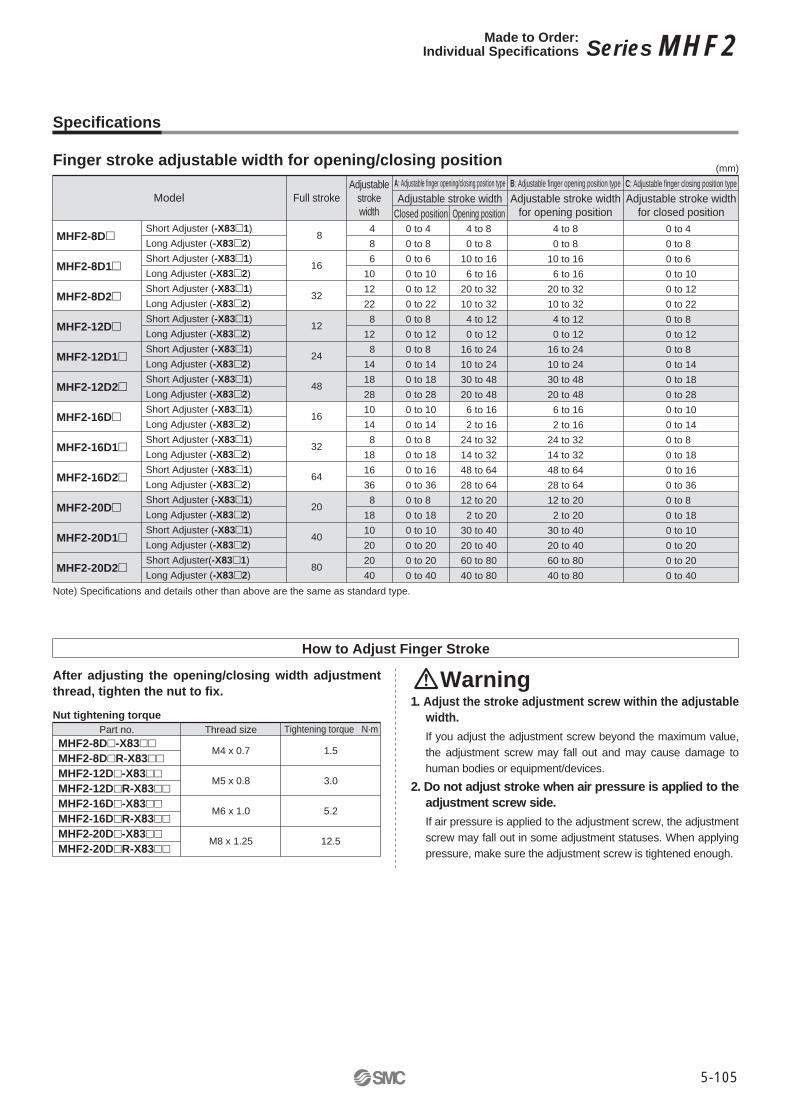
5-105
Model Full strokeAdjustable
strokewidth Closed position Opening position
Adjustable stroke widthA: Adjustable finger opening/closing position type
Adjustable stroke widthfor opening position
B: Adjustable finger opening position typeAdjustable stroke width
for closed position
C: Adjustable finger closing position type
8
16
32
12
24
48
16
32
64
20
40
80
4 8 6101222 812 81418281014 8181636 81810202040
0 to 4 0 to 8 0 to 6 0 to 100 to 120 to 220 to 8 0 to 120 to 8 0 to 140 to 180 to 280 to 100 to 140 to 8 0 to 180 to 160 to 360 to 8 0 to 180 to 100 to 200 to 200 to 40
4 to 80 to 8
10 to 16 6 to 1620 to 3210 to 32 4 to 12 0 to 1216 to 2410 to 2430 to 4820 to 48 6 to 16 2 to 1624 to 3214 to 3248 to 6428 to 6412 to 20 2 to 2030 to 4020 to 4060 to 8040 to 80
4 to 80 to 8
10 to 16 6 to 1620 to 3210 to 32 4 to 12 0 to 1216 to 2410 to 2430 to 4820 to 48 6 to 16 2 to 1624 to 3214 to 3248 to 6428 to 6412 to 20 2 to 2030 to 4020 to 4060 to 8040 to 80
0 to 4 0 to 8 0 to 6 0 to 100 to 120 to 220 to 8 0 to 120 to 8 0 to 140 to 180 to 280 to 100 to 140 to 8 0 to 180 to 160 to 360 to 8 0 to 180 to 100 to 200 to 200 to 40
(mm)
MHF2-8D�
MHF2-8D1�
MHF2-8D2�
MHF2-12D�
MHF2-12D1�
MHF2-12D2�
MHF2-16D�
MHF2-16D1�
MHF2-16D2�
MHF2-20D�
MHF2-20D1�
MHF2-20D2�
Short Adjuster (-X83�1)Long Adjuster (-X83�2)Short Adjuster (-X83�1)Long Adjuster (-X83�2)Short Adjuster (-X83�1)Long Adjuster (-X83�2)Short Adjuster (-X83�1)Long Adjuster (-X83�2)Short Adjuster (-X83�1)Long Adjuster (-X83�2)Short Adjuster (-X83�1)Long Adjuster (-X83�2)Short Adjuster (-X83�1)Long Adjuster (-X83�2)Short Adjuster (-X83�1)Long Adjuster (-X83�2)Short Adjuster (-X83�1)Long Adjuster (-X83�2)Short Adjuster (-X83�1)Long Adjuster (-X83�2)Short Adjuster (-X83�1)Long Adjuster (-X83�2)Short Adjuster(-X83�1)Long Adjuster (-X83�2)
How to Adjust Finger Stroke
After adjusting the opening/closing width adjustment
thread, tighten the nut to fix.Warning
1. Adjust the stroke adjustment screw within the adjustable
width.
If you adjust the adjustment screw beyond the maximum value, the adjustment screw may fall out and may cause damage to human bodies or equipment/devices.
2. Do not adjust stroke when air pressure is applied to the
adjustment screw side.
If air pressure is applied to the adjustment screw, the adjustment screw may fall out in some adjustment statuses. When applying pressure, make sure the adjustment screw is tightened enough.
Nut tightening torque
Part no. Thread size Tightening torque N·m
M4 x 0.7
M5 x 0.8
M6 x 1.0
M8 x 1.25
1.5
3.0
5.2
12.5
MHF2-8D�-X83��MHF2-8D�R-X83��MHF2-12D�-X83��MHF2-12D�R-X83��MHF2-16D�-X83��MHF2-16D�R-X83��MHF2-20D�-X83��MHF2-20D�R-X83��
Note) Specifications and details other than above are the same as standard type.
Specifications
Finger stroke adjustable width for opening/closing position
Series MHF2Made to Order:Individual Specifications

5-106
(E)
M1(Adjustable stroke width for closing position)M2(Adjustable stroke width for opening position)
M(Full stroke)
D(Max.)F Adjustable width
G
(For adjusting closing position)
G
(For adjusting opening position)
H
I
2 x he
xago
n widt
h acro
ss fla
ts J
2 x he
xago
n widt
h acro
ss fla
ts K
(E)
M2(Adjustable stroke width for opening position)
M(Full stroke)
D(Max.)F Adjustable width
G
(For adjusting opening position)
Hexa
gon w
idth a
cross
flats
K
(E)
M1(Adjustable stroke width for closing position)
M(Full stroke)
D(Max.)
F
Adjustable width
G
(For adjusting closing position)
Hexa
gon w
idth a
cross
flats
K
L
L
Adjustable finger opening/closing position type/MHF2-�-
Dimensions (� in the table below indicates the symbol for stroke adjustable side (A: Adjustable finger opening/closing position type, B: Adjustable finger opening position type, or C: Adjustable finger closing position type).)
Model
5
5.9
7.8
10.2
36
48
72
52
68
104
72
94
142
86
114
174
91210121318121412151823151714191828182318232333
M4 x 0.7
M5 x 0.8
M6 x 1
M8 x 1.25
15.8
20
26
33
5.9
7.7
10.6
13
2
2.5
3
4
4.6
5.4
7.4
9.9
F G H I J L M(E)D K
7
8
10
13
8
16
32
12
24
48
16
32
64
20
40
80
-X83�1-X83�2-X83�1-X83�2-X83�1-X83�2-X83�1-X83�2-X83�1-X83�2-X83�1-X83�2-X83�1-X83�2-X83�1-X83�2-X83�1-X83�2-X83�1-X83�2-X83�1-X83�2-X83�1-X83�2
X83A1X83A2
Adjustable finger opening position type/MHF2-�-X83B1X83B2
Adjustable finger closing position type/MHF2-�-X83C1X83C2
A: Adjustable finger opening/closing position type B: Adjustable finger opening position type C: Adjustable finger closing position typeM1 M2 M1 M2 M1 M2
0 to 4 0 to 8 0 to 6 0 to 100 to 120 to 220 to 8 0 to 120 to 8 0 to 140 to 180 to 280 to 100 to 140 to 8 0 to 180 to 160 to 360 to 8 0 to 180 to 100 to 200 to 200 to 40
4 to 80 to 8
10 to 16 6 to 1620 to 3210 to 32 4 to 12 0 to 1216 to 2410 to 2430 to 4820 to 48 6 to 16 2 to 1624 to 3214 to 3248 to 6428 to 6412 to 20 2 to 2030 to 4020 to 4060 to 8040 to 80
________________________
4 to 80 to 8
10 to 16 6 to 1620 to 3210 to 32 4 to 12 0 to 1216 to 2410 to 2430 to 4820 to 48 6 to 16 2 to 1624 to 3214 to 3248 to 6428 to 6412 to 20 2 to 2030 to 4020 to 4060 to 8040 to 80
0 to 4 0 to 8 0 to 6 0 to 100 to 120 to 220 to 8 0 to 120 to 8 0 to 140 to 180 to 280 to 100 to 140 to 8 0 to 180 to 160 to 360 to 8 0 to 180 to 100 to 200 to 200 to 40
________________________
(mm)
MHF2-8D�
MHF2-8D1�
MHF2-8D2�
MHF2-12D�
MHF2-12D1�
MHF2-12D2�
MHF2-16D�
MHF2-16D1�
MHF2-16D2�
MHF2-20D�
MHF2-20D1�
MHF2-20D2�
Dimensions (The dimensions below are the same as the standard type.)
Series MHF2

5-107
Mounting
Warning1. Do not scratch or dent the air gripper by dropping
or bumping it when mounting.Slight deformation can cause inaccuracy or a malfunction.
2. Tighten the screw within the specified torque range
when mounting the attachment.Tightening with a torque above the limit can cause malfunction, while insufficient tightening can cause slippage and dropping.
3. Tighten the screw within the specified torque range
when mounting the air gripper.Tightening with a torque above the limit can cause malfunction, while insufficient tightening can cause slippage and dropping.
ModelMHF2-8D�MHF2-12D�MHF2-16D�MHF2-20D�
BoltM2.5 x 0.45
M3 x 0.5M4 x 0.7M4 x 0.7
Max. tightening torque N·m0.360.631.51.5
Attachment
Make sure to mount the attachments on fingers with the tightening torque in the table below by using bolts, etc., for the female threads on fingers.
How to Mount Attachment to the Finger
How to Mount Air Grippers
Top mounting (Body tapped)
Lateral mounting (Body tapped)
Bottom mounting (Body tapped, body through-hole)
� Body tapped
� Body through-hole
Model
MHF2-8D
MHF2-12D
MHF2-16D
MHF2-20D
Bolt
M3 x 0.5M4 x 0.7M5 x 0.8M6 x 1
Max. tightening torque N·m
0.952.24.57.8
Max. screw-in depth L mm
7101215
MHF2-8D
MHF2-12D
MHF2-16D
MHF2-20D
M3 x 0.5M4 x 0.7M5 x 0.8M6 x 1
0.631.53
5.2
45
5.56
MHF2-8D
MHF2-12D
MHF2-16D
MHF2-20D
M2.5 x 0.45∗
M3 x 0.5∗
M4 x 0.7M5 x 0.8
0.360.631.53
45.2——
MHF2-8D
MHF2-12D
MHF2-16D
MHF2-20D
M3 x 0.5M4 x 0.7M5 x 0.8M6 x 1
0.631.53
5.2
45
5.56
L
L
LL
∗ � � are mounted body through-hole, use the attached special bolts.
Series MHF2 Specific Product Precautions 1Be sure to read this before handling the products.
CautionUse caution for the anti-corrosiveness of the linear guide section.Martensitic stainless steel is used for the finger guide rail, so make sure that anti-corrosiveness is inferior to the austenitic stainless steel. In particular, watch for rust in environments where waterdrops are likely to adhere due to condensation.
Operating Environment
Model Bolt Max. tightening torque N·m
Max. screw-in depth L mm
Model Bolt Max. tightening torque N·m
Max. screw-in depth L mm
Model Bolt Max. tightening torque N·m
Screw-in depth L mm

5-108
2 or
mor
eB
C
Side A
Finger reference plane
2 or m
ore
Attachment Pin insertion holeCross direction
Opening/closing direction
� Positioning in the finger’s open/close direction
Provide the following pin insertion hole dimensions: shaft-basis fitting dimension C for the open/close direction; slotted hole with relief B
� Positioning in the finger’s cross direction
Perform the positioning from the reference plane of the finger
Finite orbit type guide is used in the actuator finger
part. By using this, when there are inertial force which
cause by movements or rotation to the actuator, steel
ball will move to one side and this will cause a large
resistance and degrade the accuracy. When there are
inertial force which cause by movements or rotation to
the actuator, operate the finger to full stroke.
Especially in long stroke type, the accuracy of finger may
How to Locate Finger and Attachment
Series MHF2 Specific Product Precautions 2Be sure to read this before handling the products.
Operating Precautions
Caution