Low-Error Area-Time Efficient Fixed-Width Booth Multiplierldvan/paper_list/a low-error and... ·...
4
A Low-Error and Area-Time Efficient Fixed-Width Booth Multiplier Min-An Song, Lan-Da Van*, Ting-Chun Huang, and Sy-Yen Kuo Department of Electrical Engineering, National Taiwan University, Taipei, Taiwan, R.O.C *Chip Implementation Center (CIC), National Applied Research Laboratories, Taiwan, R.O.C. E-mail: sykuo(&cc.ee.ntu.edu.tw and ldvani cic.org.tw Abstract In this paper, we develop a new methodology for designing a lower-error and area-time efficient 2 s-complement fixed-width Booth multiplier that receives two n-bit numbers and produces an n-bit product. By properly choosing the generalized index and binary thresholding, we derive a better error-cojmpensation bias to reduce the truncation error. Since the proposed error- compensation bias is realizable, the constructing low-error fixed- width Booth multiplier is area-time efficient for VLSI implementation. Finally, we successfully apply the proposed fixed-width Booth multiplier to speech signal processing. The simulation results show that the perfoirnance isi stiperior to that using the direct-truncation fixed-width Booth multiplier. 1. Introduction In many digital signal processing (DSP) applications such as digital filters [6, 7] and wavelet transform, it is desirable to maintain fixed-width output word through tihe arithmetic operations. So, a low-error fixed-width multiplier [5-8] that receives an n-bit multiplier as well as an n-bit multiplicand and produces an n-bit output prodtict is the most important processing element for digital computing engine. In view of the algorithm level, most fixed-width multipliers are b-ased on either the Baugh- Wooley algorithm [I1 or the Booth algoirithm [2, 3 1. The Baugh- Wooley based fixed-width multipliers [5-7] have been widely studied. King and Swartzlander [5] analyzed an adaptive error- compensation bias and proposed an ri-bit fixed-width multiplier. In [6, 7], we generalized this kind of Baugh-Wooley based fixed- width multipliers by properly choosi.ng the generalized index and binary thresholding. Thus, several 'lower-error and area-efficient fixed-width multipliers can be obtained. However, the area-time efficient fixed-width multiplier cfannot be filly achieved by the Blauth-Woolcy based fixcd-wid tl nmltiplicrs. TIhercbore, thc fixed-width Bootil algoritlihi iF, currcntly onie of the rcscarclh topics. The Booth algorithm is widely used in the implementation of ASIC-oriented products because a highler-speed and smaller multiplier can be obtained. The modified Booth algorithm was proposed by the MacSorley [3] in which a triplet of bits is scanned at a time. It is known that the recoding technique of the modified Booth algorithm has two main adivantages. One is that almost half the partial products zompared to the Baugh-Wooley multiplier can be saved. Hence, the number of rows of the subproduct array can be reduced by 2. The ofther is that, based on the first advantage, the critical delay titne can, be shorter than that of the Baugh-Wooley multiplier. Area savinig of a fixed-width Booth multiplier can be achieved by directly truncating n least significant product bits and ,reserving n most significant product bits. With this method, sig,nificant truncation errors would be introduced since no error c,ompensation is considered. Thus, the Booth-based scheme in [8] has been proposed to reduce the truncation error; however, the proposed scheme [8] that lacks for systematic analysis and derivation does not be a systematic methodology. In this paper, we are motivated to propose a systematic design methodology for low-error area-time efficient Booth multipliers. The methodology includes the following steps in order: I) Propose an error-compensation bias with a new binary thresholding; 2) simulate the value of K and error performance of the proposed error-compensation bias using our generalized index, and then select the best index having lower error and satisfying the same value of K for small width n; and 3) construct a low-error Booth multiplier structure. Based on our methodology, the resulting error compensation circuit can be easily realized without any area overhead under the limited truncation error. The organization of this paper is as follows. The modified Booth algorithm is concisely reviewed in Section 2. In Section 3, we propose a better error-compensation bias and present the simulation results for small width n . The improved error-compensation bias can be mapped to a new structure. The performance of the proposed fixed-width Booth multiplier are described in Section 4. Finally, brief statements in section 5 conclude the presentation. 2. Modified Bootht Mtiltiplier Considering the multiplication of two 2 s-complemilent integers with n-bit multiplicand A and n-bit multiplier B as 2n-I P =AB= Z,P,2i i=O (1) n-2 n-2 where A= -a 2n-1 + Eai2' , B= -bn12 + Ebj2 j, and 1=O j=0 P1 denotes the 1-th output product bit. Note that a, and b, ind(licate dlata bits of multiplicand and(i miul(iplier, respectively. Assumne n is eveCI and the u-bit imultiplier Ii can be rewritten (n-2)/2 B= (b2i l+b2i-2b2i+1)2 , i=O (2) where b-1 = 0 . Note that the terms in the bracket in Eq (2) have values of {-2, -1, 0, 1, 2). Each recoded value performs a certain operation on the multiplicand A, and then the multiple additions at each stage would be required in order to generate the correct partial product. It is worth mentioning that the operation of -A can be realized by the inversion of the multiplicand and addition of 'I at the least significant bit as illustrated in Table I. Substituting Eq. (2) into Eq. (1), we can obtain Eq. (3) as (n-2)/2 (n-2)/2 P=AB= E(b2i_ ±+b2i-2b2+1,)A22i = Si, i=O i=O (3) 0-7803-8294-'s)/04/$20.00 ©2004 IEI-E 590
Transcript of Low-Error Area-Time Efficient Fixed-Width Booth Multiplierldvan/paper_list/a low-error and... ·...
A Low-Error and Area-Time Efficient Fixed-Width Booth MultiplierMin-An Song, Lan-Da Van*, Ting-Chun Huang, and Sy-Yen Kuo
Department of Electrical Engineering, National Taiwan University, Taipei, Taiwan, R.O.C*Chip Implementation Center (CIC), National Applied Research Laboratories, Taiwan, R.O.C.
E-mail: sykuo(&cc.ee.ntu.edu.tw and ldvani cic.org.tw
AbstractIn this paper, we develop a new methodology for designing a
lower-error and area-time efficient 2 s-complement fixed-widthBooth multiplier that receives two n-bit numbers and producesan n-bit product. By properly choosing the generalized index andbinary thresholding, we derive a better error-cojmpensation biasto reduce the truncation error. Since the proposed error-compensation bias is realizable, the constructing low-error fixed-width Booth multiplier is area-time efficient for VLSIimplementation. Finally, we successfully apply the proposedfixed-width Booth multiplier to speech signal processing. Thesimulation results show that the perfoirnance isi stiperior to thatusing the direct-truncation fixed-width Booth multiplier.
1. IntroductionIn many digital signal processing (DSP) applications such as
digital filters [6, 7] and wavelet transform, it is desirable tomaintain fixed-width output word through tihe arithmeticoperations. So, a low-error fixed-width multiplier [5-8] thatreceives an n-bit multiplier as well as an n-bit multiplicand andproduces an n-bit output prodtict is the most important processingelement for digital computing engine. In view of the algorithmlevel, most fixed-width multipliers are b-ased on either the Baugh-Wooley algorithm [I1 or the Booth algoirithm [2, 3 1. The Baugh-Wooley based fixed-width multipliers [5-7] have been widelystudied. King and Swartzlander [5] analyzed an adaptive error-compensation bias and proposed an ri-bit fixed-width multiplier.In [6, 7], we generalized this kind of Baugh-Wooley based fixed-width multipliers by properly choosi.ng the generalized index andbinary thresholding. Thus, several 'lower-error and area-efficientfixed-width multipliers can be obtained. However, the area-timeefficient fixed-width multiplier cfannot be filly achieved by theBlauth-Woolcy based fixcd-wid tl nmltiplicrs. TIhercbore, thcfixed-width Bootil algoritlihi iF, currcntly onie of the rcscarclhtopics.
The Booth algorithm is widely used in the implementation ofASIC-oriented products because a highler-speed and smallermultiplier can be obtained. The modified Booth algorithm wasproposed by the MacSorley [3] in which a triplet of bits isscanned at a time. It is known that the recoding technique of themodified Booth algorithm has two main adivantages. One is thatalmost half the partial products zompared to the Baugh-Wooleymultiplier can be saved. Hence, the number of rows of thesubproduct array can be reduced by 2. The ofther is that, based onthe first advantage, the critical delay titne can, be shorter than thatof the Baugh-Wooley multiplier. Area savinig of a fixed-widthBooth multiplier can be achieved by directly truncating n leastsignificant product bits and ,reserving n most significant productbits. With this method, sig,nificant truncation errors would beintroduced since no error c,ompensation is considered. Thus, theBooth-based scheme in [8] has been proposed to reduce the
truncation error; however, the proposed scheme [8] that lacks forsystematic analysis and derivation does not be a systematicmethodology. In this paper, we are motivated to propose asystematic design methodology for low-error area-time efficientBooth multipliers. The methodology includes the following stepsin order: I) Propose an error-compensation bias with a newbinary thresholding; 2) simulate the value of K and errorperformance of the proposed error-compensation bias using ourgeneralized index, and then select the best index having lowererror and satisfying the same value ofK for small width n; and 3)construct a low-error Booth multiplier structure. Based on ourmethodology, the resulting error compensation circuit can beeasily realized without any area overhead under the limitedtruncation error. The organization of this paper is as follows. Themodified Booth algorithm is concisely reviewed in Section 2. InSection 3, we propose a better error-compensation bias andpresent the simulation results for small width n . The improvederror-compensation bias can be mapped to a new structure. Theperformance of the proposed fixed-width Booth multiplier aredescribed in Section 4. Finally, brief statements in section 5conclude the presentation.
2. Modified Bootht MtiltiplierConsidering the multiplication of two 2 s-complemilent
integers with n-bit multiplicand A and n-bit multiplier B as2n-I
P =AB= Z,P,2ii=O
(1)
n-2 n-2where A= -a 2n-1 + Eai2' , B= -bn12 + Ebj2j, and
1=O j=0
P1 denotes the 1-th output product bit. Note that a, and b,ind(licate dlata bits of multiplicand and(i miul(iplier, respectively.Assumne n is eveCI and the u-bit imultiplier Ii can be rewritten
(n-2)/2B= (b2i l+b2i-2b2i+1)2 ,
i=O
(2)
where b-1 = 0 . Note that the terms in the bracket in Eq (2) havevalues of {-2, -1, 0, 1, 2). Each recoded value performs a certainoperation on the multiplicand A, and then the multiple additionsat each stage would be required in order to generate the correctpartial product. It is worth mentioning that the operation of -Acan be realized by the inversion of the multiplicand and additionof 'I at the least significant bit as illustrated in Table I.Substituting Eq. (2) into Eq. (1), we can obtain Eq. (3) as
(n-2)/2 (n-2)/2P=AB= E(b2i_ ±+b2i-2b2+1,)A22i = Si,
i=O i=O
(3)
0-7803-8294-'s)/04/$20.00 ©2004 IEI-E 590

where Si =(b2,i 1 +b2i -2b2+I)A22i , and it is known that thescanning of triplets begins from b-I to the MSB with one-bitoverlapping. Thus, only the number of n / 2 partial-product rowsneeds to be computed.
Table 1: Modified Booth Encoding Table
b21+, b2i b2i-I Operation on ADD to LSBA
o 0 0 0 00 0 1 -A 00 1 0 +A 00 1 1 +2A 01 0 0 -2A1 0 1 -A I
1 0 -A I1 1 0 0 _O
I X,7
k7 , @ 51,6
I 3~©D S. S,, s,"I XI & I4 I
I I I I l l ll
--. Tncated ptI ,r - - -- - - -
___________
'% 1 -.6 XSo., 4 S%.3 2 S .,S. I
SuI::4SA3 S,2 SM S, -I,IIQ,12],oIS, S;, S2t --
IIl>13121Cr'
) t
tVVV1 t -t tP15 P14 P13 P12 PllPIO P9 P8 's"Fig. 1. Modified Booth partial-product diagram with sign-generate sign extension scheme for an 8x8 multiplier.
So as to simplify the representation of the bit-product of eachrow for the Booth algorithm, we define the following notation
S ,n22i+n-lI 2i+n-2 S 2i2S1 "i,n-l~ + Si,n-22 +..+ S1,0 (4)
where S,jj represents the bit product of the i-th row. Based on
the conventional Booth arithmetic operations, sign extension ofthe partial products are required for each stage. However, theextended sign bits result in a larger power and area. According tothe sign-generate sign extension scheme [4], for an 8 by 8multiplier, the sign of the final result can be expressed as
1J 232
iJ 9
s-(So,72)2+(SI7Z2') 2 (S2,7Z2')24 +(S3,7Z2J)26j=8 j=8 j=8 j=8
9 8 - 1 13 12=(2 +S0,72 )+(2" +S 2721 )+(2 +S2 72 )
+(2" +S32 4)+22 (5)
where S is the final result sign. From Eq. (5), the partialproducts of the Booth algorithm only need to add two elements(1, Si7 ) for each row and add an extra 'I in the 28 -weightposition as shown in Fig. 1, where main and remain representmain part and remain part of the least significant bit (LSB),respectively. Thus, the sign-generate sign extension scheme canreduce a lot of redundant full adders compared to theconventional sign extension method. The architecture of theBooth Multiplier as shown in Fig.2 consists of Booth encoders,selectors (sel), full adders (FA) and half adders (HA). The Boothencoder generates Ctrli [O: 2] signals to control the selector to
choose -2A, -A, 0, IA or 2A.
3. Design of Fixed-Width Booth MultiplierThe 2n product for n by n 2 s-complement multiplication can
be divided into two sections as
P = AB = MP + LP. (6)
Fig. 2. An 8 X 8 modified Booth multiplier using sign-generatesign extension scheme.
The most accurate trunication1prodLlct is giveni by
P_MP++ aTempx2n,
UTemp =ILPI r -
(7)
(8)
Without loss of generality, for n=8, Eq. (8) can be denoted as
I
(S3,1 + S2.3 + S '0,7 )-+22 (S3,0 + - + SO,6L2 22Cr7eml9) 1
+ CfrI3[2D+ ...+I
So, I + I! (SO,O + Ctrlo[2 1) r
(9)Then we define the following terms
Emain = S3,1 + S2,3 + SI,s + SO,7,
Eremain =I (S3o0 + S2,2 + Sj,4 + SO,6 + Ctrl3(21)2'
+... + 7 (So,o + Ctrlo[2])27Thus;, we can rewrite Eq. (9) as
cr Temp = [I(Emain + Eremain )]-
(10)
(I 1)
(12)
591
a I i i a 2 .i % - - - -
It is convenient to perform exhaustive simulation if we define thegeneralized index. Here the generalized index for 8 by 8multipliers is defined as
i9M&x(q32q22q71qO) =< S3,1 >q3 + < S2,3 >q2 + < S1,s >q + < So,7 >q (13)
where the binary parameters q3, q2,q1 and qo E (0,1), and theoperator
< TT ,if q, =0(T, ,if q = I
(14)
in which T is the complement of binary T . Furthermore,0indeX(q3,q2,ql,qO) is referred to as as 0Q, where
Q=q3x23 +q2 x22 +q1 X21 +qo x20. (15)
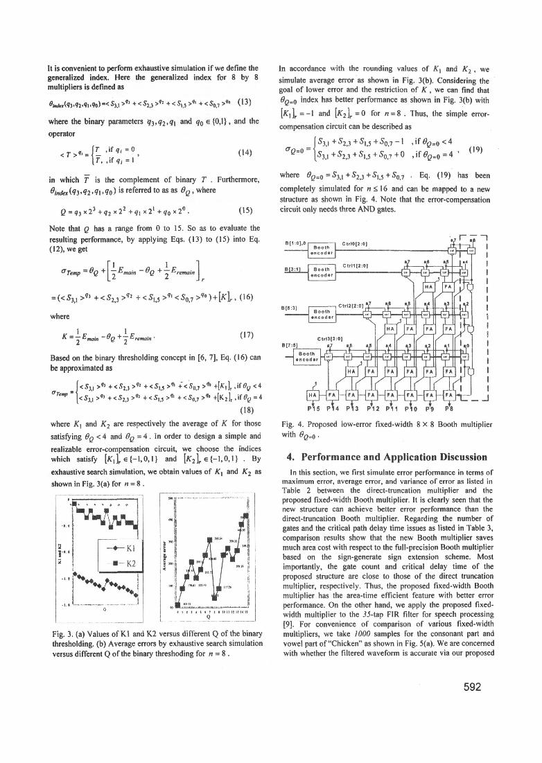
In accordance with the rounding values of K1 and K2, wesimulate average error as shown in Fig. 3(b). Considering thegoal of lower error and the restriction of K, we can find thatOQ=O index has better performance as shown in Fig. 3(b) with
[KI Jr = -I and [K2 Jr = 0 for n = 8 . Thus, the simple error-compensation circuit can be described as
S3,1+S2,3 +S,,5 +S0,7 -1 , if OQ=o < 4aQ=o = S3,1 + S2,3 +S+,s + S0.7 + ° , ifOQ=0 = 4 (19)
where Q=O= S31 + S23 + S5 +So,7 * Eq. (19) has been
completely simulated for n . 16 and can be mapped to a newstructure as shown in Fig. 4. Note that the error-compensationcircuit only needs three AND gates.
Note that Q has a range from 0 to 15. So as to evaluate theresulting performance, by applying Eqs. (13) to (15) into Eq.(12), we get
6Temp = OQ + [ Emain 0Q + I Eremain]
=w(<e3r q3 +<S23 >92 + <eS15 >q, <SO7 qo )+[K]r 9 (16)where
K = 2 Emain - fQ +I Eremain° (17)
Based on the binary thresholding concept in [6, 7], Eq. (16) canbe approximated as
[<S3.1 >9) + <S2.3 >9' +< SO >q' +<SOJ7 >q° 44K, 1r if Oy < 4emp {<S3,1 >71 +<S2,3 >92 +<S1,, >9 +<s0,7 >q +[K2] , if =4
(18)where K1 and K2 are respectively the average of K for thosesatisfying OQ < 4 and =Q4. In order to design a simple andrealizable error-compensation circuit, we choose the indiceswhich satisfy [KuIr,e (l,0,l) and [K2J]rE{-1,0,1) . Byexhaustive search simulation, we obtain values of K1 and K2 as
shown in Fig. 3(a) for n= 8 .
-EK2 20 m
Q 20
Fig. 3. (a) Values of KI and K2 versus different Q of the binarythresholding. (b) Average errors by exhaustive search simulationversus different Q of the binary threshoding for n = 8 .
B[:3:1 | Booth |Ctrli(2:01 ,4
P P 12 Pa11 P 0 P9 PS
Fig. 4. Proposed low-error fixed-width 8 x 8 Booth multiplierwith
4. Performance-and Application DiscussionIn this section, we first simulate error performance in terms of
maximum error, average error, and variance of error as listed inTrable 2 between the direct-truncation multiplier and theproposed fixed-width Booth multiplier. It is clearly seen that thenew structure can achieve better error performance than thedirect-truncation Booth multiplier. Regarding the number ofgates and the critical path delay time issues as listed in Table 3,comparison results show that the new Booth multiplier savesmuch area cost with respect to the full-precision Booth multiplierbased on the sign-generate sign extension scheme. Mostimportantly, the gate count and critical delay time of theproposed structure are close to those of the direct truncationmultiplier, respectively. Thus, the proposed fixed-width Boothmultiplier has the area-time efficient feature with better errorperformance. On the other hand, we apply the proposed fixed-width multiplier to the 35-tap FIR filter for speech processing(9]. For convenience of comparison of various fixed-widthmultipliers, we take 1000 samples for the consonant part andvowel part of "Chicken" as shown in Fig. 5(a). We are concernedwith whether the filtered waveform is accurate via our proposed
592

fixed-width multiplier, so the correct standard output is required.We use error-free output as a standard, which is used to comparethe accuracy performances of fixed-width multipliers. Fig. 5(b)shows the standard filtering output signals and Figs. 5(c) showsthe filtering output signals processed by the 35-tap low-pass FIRfilter applying a direct truncation fixed-width multiplier. Usingdirect truncation multiplier, it is seen from Fig. 5(c) that there arelarge average error and variance of errors in the consonant part.The smaller average error and variance of the errors especiallyfor consonant part is obtained by using our proposed fixed-widthBooth multiplier as shown in Fig. 5(d).
5. ConclusionsThis paper develops a new methodology for designing a low-
error and area-time efficient fixed-width Booth multiplier. Byproperly choosing binary thresholding and the generalized index,we can derive a better error-compensation bias to improve thetruncation error. Furthermore, this error-compensation bias canbe easily constructed as a lower-error fixed-width Boothmultiplier. It is very suitable for VLSI digital signal processingapplications where the accuracy, area, and speed issues arecrucial. Finally, we successfully apply the proposed fixed-widthmultiplier to a digital FIR filter for speech processingapplication.
(a)
11'..Ig;, tt, s.. 18
tw s.,. j,,
,g, 11l;1n'1',''
.* .... ., ,* .w .... .0
(b)
(c) (d)Fig. 5. (a) Original input voice signal, (b) standard output voicesignal, (c) output signals using the direct truncation structure and(d) output signals using the proposed Booth multiplier structure.
6. References[I] C. R. Baugh and B. A. Wooley, "A two's complement
parallel array multiplication algorithms", IEEE Trans.Comput., vol. C-22, pp. 1045-1047, Dec. 1973.
(2] A. D. Booth, "A signed binary multiplication technique,"Quarterly Journal of Mechanics and Applied Mathematics,vol. 4, part 5, pp. 236-240, 1951.
[3] 0. L. MacSorley, "High-speed arithmetic in binarycomputer", Proc. IRE, vol. 49, pp. 67-91, 1961.
[4] E. de Angel and E. E. Swartzlander, Jr., "Low powerparallel multipliers," IEEE VLSI Signal Processing IX, 1996,pp. 199-208.
(5] E. E. Swartzlander, Jr., "Truncated multiplication withapproximate rounding," in Proc. 33rd Asilomar Conferenceon Signals, Systems, and Computers, 1999, vol. 2, pp. 1480-1483.
[6] L. D. Van, S. S. Wang, and W. S. Feng, "Design of thelower-error fixed-width multiplier and its application",IEEE Trans. Circuits Syst. 11, vol. 47, pp. 11 12-1118, Oct.2000.
(7] L. D. Van and S. H. Lee, "A generalized methodology forlower-error area-efficient fixed-width multipliers," in Proc.IEEE Int. Symp. Circuits Syst., May 2002, vol. 1, pp. 65-68,Phoenix, Arizona.
[8] S. J. Jou and H. H. Wang, "Fixed-width multiplier for DSPapplication," IEEE Int. Conf Computer Design, Sep. 2000,pp. 318-322.
[9] M. E. Paul, and K. Bruce, C Language Algorithms forDigital Signal Processing. Englewood Cliffs, NJ: Prentice-Hall, 1991.
Table 2: Comparison Results ofThree Kinds of Errors amongDifferent Booth Multipliers
Multiplier Width Maximu Average Variance ofm Error Error Error
Direct 4 32 10.88 67.20Truncation 6 192 70.50 1465.86Multiplier 8 1024 384.25 28510.19
_ 16 524288 196608.25 3661149123'This Work 4 16 4.59 28.50
6 85 21.60 716.868 443 103.12 16376.6516 504268 62501.62 1486362529
Table 3: Comparison Results of Area and Critical Delay Timeamong Different Booth Multipliers for n = 8
Multiplier Area (# of gate counts) Critical DelayTime
FA VIA SelectorlFull lPrecisioniMultiplier 28 12 36 1 37TrA + 3TIjA
Based on Sign-Generate
Direct 1 8 16 7TFA + 3THATruncationMultiplierThis work 16 4 20 1 OTFA + TIM
593
1Se..I
la
I
I
.04
As
of
of
I 1 -1,7,rrr
0
It -, i;i i4,
1,1,11,1,1,l,11t
i
i4i ." It"
,i I