Low-Cost, Low-Energy Concentrate Water Desalination Using ...
88
Low-Cost, Low-Energy Concentrate Water Desalination Using Heat Recuperative Solar Still with Concentrating Solar Technology Desalination and Water Purification Research Program Research and Development Office Report No. NMSU004 New Mexico Water Resources Research Institute Technical Completion Report No. 387 U.S. Department of the Interior October 2020
Transcript of Low-Cost, Low-Energy Concentrate Water Desalination Using ...

Low-Cost, Low-Energy Concentrate Water Desalination Using Heat Recuperative Solar Still with Concentrating Solar Technology Desalination and Water Purification Research Program Research and Development Office Report No. NMSU004
New Mexico Water Resources Research Institute Technical Completion Report No. 387
U.S. Department of the Interior October 2020

REPORT DOCUMENTATION PAGE Form Approved OMB No. 0704-0188
The public reporting burden for this collection of information is estimated to average 1 hour per response, including the time for reviewing instructions, searching existing data sources, gathering and maintaining the data needed, and completing and reviewing the collection of information. Send comments regarding this burden estimate or any other aspect of this collection of information, including suggestions for reducing the burden, to Department of Defense, Washington Headquarters Services, Directorate for Information Operations and Reports (0704-0188), 1215 Jefferson Davis Highway, Suite 1204, Arlington, VA 22202-4302. Respondents should be aware that notwithstanding any other provision of law, no person shall be subject to any penalty for failing to comply with a collection of information if it does not display a currently valid OMB control number. PLEASE DO NOT RETURN YOUR FORM TO THE ABOVE ADDRESS.
1. REPORT DATE (DD-MM-YYYY) October 2020
2. REPORT TYPE Final
3. DATES COVERED (From - To) April 2017 to December 2019
4. TITLE AND SUBTITLE Low-Cost, Low-Energy Concentrate Water Desalination Using Heat Recuperative Solar Still with Concentrating Solar Technology
“Solar Still with Concentrating Solar Technology”
5a. CONTRACT NUMBER Agreement No. R16AC00002 5b. GRANT NUMBER 5c. PROGRAM ELEMENT NUMBER
6. AUTHOR(S) Sarada Kuravi, Pei Xu, Krishna Kota, Young-Ho Park and Huiyao Wang
5d. PROJECT NUMBER
5e. TASK NUMBER
5f. WORK UNIT NUMBER
7. PERFORMING ORGANIZATION NAME(S) AND ADDRESS(ES) Department of Mechanical and Aerospace Engineering, New Mexico State University, Las Cruces, NM, 88003, USA
8. PERFORMING ORGANIZATION REPORT NUMBER
9. SPONSORING/MONITORING AGENCY NAME(S) AND ADDRESS(ES) Bureau of Reclamation U.S. Department of the Interior Denver Federal Center PO Box 25007, Denver, CO 80225-0007
10. SPONSOR/MONITOR'S ACRONYM(S) Reclamation 11. SPONSOR/MONITOR'S REPORT NUMBER(S) DWPR Report No. NMSU004
12. DISTRIBUTION/AVAILABILITY STATEMENT Available from https://www.usbr.gov/research/dwpr/DWPR_Reports.html
13. SUPPLEMENTARY NOTES
14. ABSTRACT This work investigated new solar collection and heat transport approaches to significantly enhance the solar input and phase change processes in a solar still to realize high desalination rates. This research studied the following novel techniques and analyzed their potential to improve the productivity of a solar still: (i) use of an external point-focusing Fresnel lens to amplify solar insolation (or energy input per m2 to achieve boiling); (ii) use of a superhydrophobic surface on glass cover to reduce the water layer thickness (and hence improve condensation); (iii) use of hydrophilic surfaces to enhance the heat transfer rate by increasing wettability at the basin-water interface; and (iv) use of interfacial evaporation materials to enhance evaporation (water-vapor interface). The effect of each of these enhancements was analyzed separately using systematic experiments and analytical modeling. It was found that the Fresnel lens improved productivity by 467% under the conditions tested. The hydrophobic glass cover coatings showed lower productivity compared to no coatings. Increasing wettability on an aluminum surface showed a 15-20% increase in water productivity. The evaporation efficiency using 10CBMCE under 5-suns was 1.53 times that of evaporation without the photothermal membrane. 15. SUBJECT TERMS Solar still; Water purification; Concentrating solar power; Interfacial evaporation 16. SECURITY CLASSIFICATION OF: 17.
LIMITATION OF ABSTRACT
18. NUMBER OF PAGES
19a. NAME OF RESPONSIBLE PERSON Katherine (Katie) Guerra
a. REPORT U
b. ABSTRACT U
THIS PAGE U
19b. TELEPHONE NUMBER (Include area code) 303-445-2013
Standard Form 298 (Rev. 8/98) Prescribed by ANSI Std. Z39.18

Desalination and Water Purification Research Program Report No. NMSU004
New Mexico Water Resources Research Institute Technical Completion Report No. 387
Low-Cost, Low-Energy Concentrate Water Desalination Using Heat Recuperative Solar Still with Concentrating Solar Technology Prepared for the Bureau of Reclamation Under Agreement No. R16AC00002
by
Sarada Kuravi, Mechanical and Aerospace Engineering Pei Xu, Civil Engineering Krishna Kota, Mechanical and Aerospace Engineering Young-Ho Park, Mechanical and Aerospace Engineering Huiyao Wang, Civil Engineering
New Mexico State University Las Cruces, New Mexico
U.S. Department of the Interior October 2020
i
Mission Statements The Department of the Interior (DOI) conserves and manages the Nation’s natural
resources and cultural heritage for the benefit and enjoyment of the American people, provides scientific and other information about natural resources and natural hazards to address societal challenges and create opportunities for the American people, and honors the Nation’s trust responsibilities or special commitments to American Indians, Alaska Natives, and affiliated island communities to help them prosper.
The mission of the Bureau of Reclamation is to manage, develop, and protect water and
related resources in an environmentally and economically sound manner in the interest of the American public.
Disclaimer The views, analysis, recommendations, and conclusions in this report are those of the
authors and do not represent official or unofficial policies or opinions of the United States Government, and the United States takes no position with regard to any findings, conclusions, or recommendations made. As such, mention of trade names or commercial products does not constitute their endorsement by the United States Government.
Acknowledgments The Desalination and Water Purification Research and Development Program, Bureau of Reclamation, sponsored this research from a cooperative agreement between the U.S. Bureau of Reclamation (BOR) and New Mexico State University (#R16AC00002, Center for the Development and Use of Alternative Water Supplies). We acknowledge the scholarship provided by USDA Wheels of Change program. We acknowledge the contribution of our students: Lei Mu, Lin Chen, Claire Debroux, Victoria Clarke, Lazar Cvijovic, Rocio Castillo Gomez, and Ana Johnson.

Acronyms and Abbreviations
ii
AFRL Fresnel lens area, m2
AER Average evaporation rate BiS Binary surfaces CBNP Carbon black nanoparticles CF Carbon fiber CBMCE Carbon black deposited on mixed cellulose ester CBNP Carbon black nanoparticles Cs Present capital cost of the solar still dw Saline water depth, m ED Electrodialysis EDR Electrodialysis reversal
FRL Fresnel lens, Experiment group accounting for the effects of Fresnel lens
FAS Tridecafluoroctyltriethoxysilane HHPW High hourly productivity window INF Interfacial nanocomposite films i Interest rate on annual basis I(t) Intensity of solar radiation, W/m2
Ieff(t) Effective Solar Intensity with Fresnel lens, W/m2
IES Intensity of solar radiation on the ground, W/m2
ITP Intensity of solar radiation on the mirror platform base, W/m2
LMH Liter per square meter per hour MCE Mixed cellulose ester md Mean daily distillate output M yearly Average annual productivity in liters n Expected useful life of the solar still in years ND Number of clear days OMC Annual operation and maintenance costs RO Reverse Osmosis S Salvage value of the solar still in the future SEM Scanning electron microscope SP Selling price of distilled water per liter Ta Ambient temperature, ºC TDS Total dissolved salts TEOS Tetraethyl orthsilicate TOC Total organic content Tw Saline water temperature, ºC Tgi temperature of the inner surface of glass cover, ºC Tgo temperature of the outer surface of glass cover, ºC UV-Vis-NIR Ultraviolet-visible-near infrared VSEP Vibratory shear enhanced membrane filtration processes WD Experiment group accounting for the effects of dw
η Daily efficiency ZLD Zero liquid discharge

Measurements
iii
°C Degree Celsius m Meter m2 Square meter W/m2 Watt per square meter L/m2/day Liter per square meter per day L/m2 Liter per square meter L/m2/hour Liter per square meter per hour mg/L Milligrams per liter m/s Meter per second µS/cm Microsiemens/centimeter kJ/kg Filojoule/kilogram W/m K Watt per meter per Kelvin degree W/m2 K Watt per square meter per Kelvin degree kJ/kg K Kilojoule per kilogram per Kelvin degree W/m2k4 Watt per square meter per ° Angle

Solar Still with Concentrating Solar Technology
iv
Contents
Page Mission Statements ......................................................................................................................................... i Disclaimer ........................................................................................................................................................ i Acknowledgments........................................................................................................................................... i Acronyms and Abbreviations ....................................................................................................................... ii Measurements ................................................................................................................................................ iii Figures ............................................................................................................................................................ vi Tables ............................................................................................................................................................. vii Executive Summary ...................................................................................................................................... ix 1. Introduction ............................................................................................................................................... 1
1.1. Project Background ..........................................................................................................................1 1.1.1. Problem ....................................................................................................................................2
1.2. Project Needs and Objectives .........................................................................................................2 1.2.1. Needs ........................................................................................................................................2 1.2.2. Objectives ................................................................................................................................3
1.3. Project Overview ..............................................................................................................................4 1.3.1. Overall Approach and Concepts ..........................................................................................4
2. Amplifying Solar Input ............................................................................................................................. 5 2.1. Experimental Setup ..........................................................................................................................5
2.1.1. Initial Design – Double-Slope Solar Still ............................................................................5 2.1.2. Single-Slope Solar Still ............................................................................................................6 2.1.3. Experiments.............................................................................................................................7 2.1.4. Key Results ..............................................................................................................................8
2.2. Thermal Model ............................................................................................................................... 11 2.2.1. Key Results and Comparison with Experiment .............................................................. 12
3. Enhancing the Evaporation Rate .......................................................................................................... 13 3.1. Evaporation at the Water-vapor Interface Using Carbon Fibers ........................................... 13
3.1.1. Key Results ........................................................................................................................... 14 3.2. Evaporation at Water-vapor Interface Using Photothermal Membranes ............................. 15
3.2.1. Key Results ........................................................................................................................... 18 3.3. Evaporation at Basin-water Interface Using Hydrophilic Surfaces ........................................ 22
3.3.1. Experiments and Key Results ............................................................................................ 23 4. Enhancing the Condensation Rate ........................................................................................................ 25
4.1. Superhydrophobic coatings on glass cover ................................................................................ 25 4.1.1. Key Results ........................................................................................................................... 27
5. Economic Analysis .................................................................................................................................. 29 5.1 Solar Still with Fresnel Lens .......................................................................................................... 29 5.2 Solar Still with Fresnel Lens and Interfacial Evaporation Materials ....................................... 30
6. Conclusions .............................................................................................................................................. 32 6.1. Conclusions .................................................................................................................................... 32 6.2. Recommended Next Steps ........................................................................................................... 32
7. References .................................................................................................................................................. 33 Appendix - A: Products .............................................................................................................................. 37
Products: ................................................................................................................................................. 37 Papers published/In preparation ................................................................................................. 37 Poster Presentations. ...................................................................................................................... 37

Solar Still with Concentrating Solar Technology
v
MS Thesis ................................................................................................................................................ 37 Students ........................................................................................................................................... 38 Proposals Funded ........................................................................................................................... 38
Appendix - B: Double-Slope Solar Still .................................................................................................... 39 Experimental Setup ................................................................................................................................ 39 Results ..................................................................................................................................................... 41
Appendix - C: Centralized Mirror Technique .......................................................................................... 45 Solar Field Design ................................................................................................................................. 45 Solar tracker design ................................................................................................................................ 45 Convex mirror design ........................................................................................................................... 48 Preliminary Tests .................................................................................................................................... 50
Appendix - D: Binary Surfaces .................................................................................................................. 53 Preparation .............................................................................................................................................. 53 Testing the BiS for corrosion resistance ............................................................................................ 53
Appendix - E: Superhydrophobic Coatings on Glass Cover ................................................................ 55 Effects of salinity on the evaporation performance of still A without coating ............................ 56 Effects of slope angles of the glass covers on the performance of the stills ................................ 58
Appendix - F: Preliminary Economic Analysis for a Centralized Mirror ............................................. 59 Preliminary Analysis for a Centralized Mirror ................................................................................... 59
Appendix - G: Thermal Model Parametric Study......................................................................................61 Parametric Study: Effect of geographic location ...............................................................................62
Appendix - H: Literature Review on Various Solar Stills ........................................................................67 References for Appendix H....................................................................................................................72

Solar Still with Concentrating Solar Technology
vi
Figures
Page Figure 1-1. Heat transfer process in a solar still......................................................................................... 3 Figure 2-1. Initial design of Solar Still: Test setup with Fresnel lens ...................................................... 6 Figure 2-2. Fabricated single-slope still (left), assembled test setup (right) ........................................... 7 Figure 2-3. Accumulated and hourly system yields with and without FRL ........................................... 9 Figure 2-4. Accumulated and hourly system yields for different water depths ..................................... 9 Figure 2-5. Heat transfer process in a solar still. ...................................................................................... 11 Figure 2-6. Hourly variation of experimental and theoretical values of water temperatures ............ 12 Figure 3-1. CF cluster preparation. ............................................................................................................ 13 Figure 3-2. Set-up of outdoor solar evaporation with carbon fiber ...................................................... 13 Figure 3-3. Effects of peak solar radiation on daily output of clean water without CF in still A ..... 14 Figure 3-4. Effects of peak solar radiation on daily output of clean water with CF .......................... 14 Figure 3-5. Comparison of evaporation rate with and without CF ...................................................... 15 Figure 3-6. Fabrication of CBNPs based photothermal membrane ..................................................... 16 Figure 3-7. UV-Vis-NIR absorption spectra of the prepared membranes: (a) Transmission, (b) Reflectance, (c) Absorbance, (d) Set-up of the solar vapor generation system, and (e) Top view of CBMCE membrane during the evaporation experiments ................................................................. 17 Figure 3-8. TEM image of CBNPs in dispersion .................................................................................... 17 Figure 3-9. SEM images of top surfaces of (a) pristine MCE, (b) 0.8CBMCE, (c) 2CBMCE, (d) 4CBMCE, (e) 10CBMCE, and (f) 20CBMCE ......................................................................................... 18 Figure 3-10. Evaporation performance of deionized water using CBNPs-based photothermal membranes with different normalized loading of CBNPs under 5-suns irradiation at relative humidity of 54%: (a) surface temperature variation with evaporation time, (b) Comparison. ......... 19 Figure 3-11. Comparison of (a) AER and (b) evaporation efficiency performance for evaporation of 13.5 wt.% NaCl solution with water depth of 9 cm under 5-suns radiation at relative humidity of 54% ......................................................................................................................... 20 Figure 3-12. Evaporation performance of 13.5 wt.% NaCl solution at various water depths under 5-suns irradiation and relative humidity of 54% .......................................................................... 20 Figure 3-13. The average evaporation rate of different water types using 10CBMCE membrane for 60 min evaporation with water depth 9 cm under 5-suns insolation and relative humidity of 54% ........................................................................................................................................... 21 Figure 3-14. A 5 µL water droplet wetting and spreading on a paper towel-like aluminum surface; the inset shows a 5 µL sessile droplet on a polished aluminum surface (polished using 1200 grit paper) ............................................................................................................................................ 22 Figure 3-15. An ultra-omniphilic aluminum surface observed under a SEM under different resolutions (× 37 to × 32,000) and at various locations on the same sample ..................................... 23 Figure 3-16. Schematic of the test setup for boiling tests ...................................................................... 24 Figure 4-1. Solar still A with a tilt angle of 66 degrees ........................................................................... 25 Figure 4-2. Two identical solar stills B with a slope angle of 26 degrees in order to compare the impact of hydrophobic coating .................................................................................................................. 26 Figure 4-3. Preparation of coating solution .............................................................................................. 26 Figure 4-4. Coating on glass slides ............................................................................................................. 27 Figure 4-5. Average fresh water output and maximum hourly yield of still A with and without silica coating .................................................................................................................................................. 27 Figure 4-6. Distillate output of still B before and after silica coating ................................................... 28 Figure 4-7. Effect of cooling on distillate output of still B (water flow rate is 400 ml/min) ............ 28

Solar Still with Concentrating Solar Technology
vii
Tables
Page
Table 2-1. Experimental matrix.................................................................................................................................8 Table 2-2. System efficiencies observed in the tests performed ............................................................10 Table 5-1. Cost comparison between different solar still configurations based on results obtained ......29 Table 5-2. Cost estimate of materials for a 1 m2 solar still ...............................................................................30 Table 5-3. Life cycle cost of a solar still to treat 13.5% saline water for clean water production............31

Solar Still with Concentrating Solar Technology
viii

Solar Still with Concentrating Solar Technology
ix
Executive Summary This research studied different novel techniques and analyzed their potential to improve
the productivity of a solar still under the Bureau of Reclamation’s (Reclamation) Desalination and Water Purification Program (DWPR), under a cooperative agreement between Reclamation and New Mexico State University (#R16AC00002, Center for the Development and Use of Alternative Water Supplies). Despite numerous advances on solar stills, only a small percentage of reclaimed water is produced via solar still among various water desalination techniques due to the associated low productivity. The objectives of this project are to improve the productivity of a solar still by (i) enhancing the solar input, (ii) enhancing the evaporation rate, (iii) enhancing the condensation process, and (iv) performing an economic analysis of each of the individual enhancements. A brief description of the technical approach and work accomplished under each of the objectives is included below. Details are provided in later sections of the report.
1. Amplifying solar input to enable rapid evaporation
The solar heat input is increased by using an external point-focusing Fresnel lens (FRL) to focus sunlight directly onto the still. To achieve this objective, we built and tested two different laboratory-scale solar still systems (double slope and single slope) and analyzed the solar amplification technique for its solar enhancement potential. It was found that the FRL induced the boiling process inside the solar still at the focal point, and it was shown to be effective in increasing productivity. A high hourly productivity window was observed due to the presence of boiling. The highest total productivity was found to be 9.22 L/m2/day, which is a 467.4% enhancement in comparison with 1.625 L/m2/day for the case without FRL. A maximum system efficiency increase of about 84.7% was observed in the experiments.
A thermal model that comprehensively simulates the heat transfer inside a solar still was
also developed in this project, which showed good agreement with experiments. The effect of FRL was accounted for by increasing the solar insolation parameter in the model.
2. Enhancing the evaporation rate
For enhanced evaporation, we fabricated two different interfacial evaporation materials for their potential to enhance the surface evaporation (from water and vapor interface) in a solar still: (i) use of carbon nanofibers enhanced the evaporation rate by 30.1%; and (ii) use of carbon black nanoparticle photothermal membranes showed an increase in evaporation efficiency of 1.53 times. A maximum productivity of 63% was observed when the heat input was around five times the normal solar insolation (5-suns).
To increase the transfer rate of heat at the basin, we tested the possibility of using
hydrophilic surfaces on the basin. The hydrophilic surfaces showed an enhanced potential (15% improvement in productivity compared to plain surfaces); however, they also showed an increase in corrosion. We also began testing new surfaces called binary surfaces, which showed some potential (50% reduction in corrosion and a 15% increase in productivity.
3. Enhancing the condensation rate
We fabricated and analyzed superhydrophobic glass cover surfaces to test their performance to enhance condensation. However, we found that the results were not as expected, mainly because the water droplets fell back into the still when the superhydrophobic

Solar Still with Concentrating Solar Technology
x
surfaces were used. For the experimental parameters used, we tested the effect of an external air-cooling mechanism for improving the condensation. It was observed that increasing the forced cooling velocity of air increased the condensation rate.
4. Performing an economic analysis of each of the individual enhancements
We performed an economic analysis to compare the cost of water with and without each enhancement technique. Using a Fresnel lens showed the cost of water was reduced from $0.042/L-m2 to $0.014/L-m2. Using the interfacial membranes and FRL, the scaled-up system life-cycle cost was found to be between $0.0056/L-m2 and $0.012/L-m2.

Solar Still with Concentrating Solar Technology
1
1. Introduction Meeting the increasing demand for fresh water is a grand challenge. Desalination and water
reuse have become two key solutions to addressing water shortages and sustainability. Desalting technologies such as reverse osmosis (RO) are a primary method for treating impaired waters because they are effective at removing most of the contaminating constituents. The primary shortfall of RO is management and disposal of the highly saline concentrate laden with accumulated contaminants (Mickley, 2009; Xu et al., 2013). This brine stream represents a significant loss of water, and is often associated with expensive concentrate treatment. While ocean disposal is used widely in coastal areas for disposal of the saline concentrates, inland communities are confronted with more limited and challenging disposal issues (Mickley, 2009).
Thermal processes using brine concentrator and crystallizer are considered mature
industrial technologies to achieve zero liquid discharge (ZLD) or near-ZLD of concentrate from low to high salinity, albeit at high costs and intensive energy demand. Several emerging and hybrid treatment technologies have been investigated to improve concentrate management and recovery, such as dewvaporation (Beckman, 2008), membrane distillation (Martinetti et al., 2009), forward osmosis (Martinetti et al., 2009), electrodialysis (ED) (Sethi et al., 2009; Zhang et al., 2011; Zhang et al., 2012), electrodialysis reversal (EDR) (Xu et al., 2013; Reahl, 1992), electrodialysis metathesis (Bond et al., 2011), various intermediate precipitation processes followed by secondary RO (Gabelich et al., 2007; Rahardianto et al., 2010), and vibratory shear enhanced membrane filtration processes (VSEP) (Lozier et al., 2007). These systems can achieve additional water recovery for desalination of concentrates. New research trends are striving to recover salts and other valuable products from concentrate (Badruzzaman et al., 2009; Davis, 2006; Ravizky and Nadav, 2007; Xu et al., 2013). Previous studies have focused on improving overall water recovery and providing freshwater; these technologies, however, are often costly and energy-intensive. A cost-effective alternative is to treat concentrate using solar energy, which will increase the use of renewable energy, thus reducing energy demand and costs for desalination and concentrate treatment. Currently, desalination using solar energy is achieved by using solar thermal collectors, solar ponds, or solar photovoltaics (Gude et al., 2011; Xu et al., 2013). A very simple and effective technology for direct desalination is by utilizing a solar still, where the heat collection and the distillation are achieved in the same equipment (Hasnain and Alajlan, 1998; Velmurugan et al., 2009).
1.1. Project Background The overarching goal of the study was to explore and develop innovative solar collection
and heat transport/management approaches in bottom-up thermal process design for realizing a scalable, low-cost, low-energy solar still with rapid desalination capability for RO concentrate management and energy recovery. The study will have a significant impact on increasing the usable water supply in the United States through the treatment and desalination of impaired waters. The proposed technologies are also attractive for enhancing the water available in small and rural communities in the southwestern United States where water shortages occur

Solar Still with Concentrating Solar Technology
2
frequently. The processes described are scalable, cost effective, and can be used for fresh water supply in remote and arid areas.
1.1.1. Problem A solar still is an impactful device for producing freshwater from brine/wastewater by sole
or partial consumption of solar energy. Solar stills have been deemed as a promising device to augment freshwater supply due to advantages such as low maintenance cost, affordability, and simplicity. In general, a solar still can be classified into two types: namely, passive solar stills and active solar stills (Rufuss et al., 2016). In a passive still, evaporation and condensation occur in a natural way, whereas an active solar still fundamentally consumes electricity to improve its productivity by utilizing additional elements such as pumps, fans, external condensers, and a solar tracking system. In recent years, numerous solar still designs (Kumar et al., 2015) and enhancement strategies (Kabeel et al., 2015; Sivakumar and Sundaram, 2013; Xiao et al., 2013) have been proposed. Among the suggested designs are inclined solar stills (Kaviti et al., 2016), pyramid solar stills (Nayi and Modi, 2018), special still designs (Durkaieswaran and Murugavel, 2015), and solar stills with reflectors (Omara et al., 2017). Up-to-date methods to increase solar still productivity include (a) the nano-coating technique to tailor the condensing surface (Zanganeh et al., 2019) and (b) the solar-driven interfacial evaporation approach to increase the efficiency of vapor generation in a novel floating solar still (Ni et al., 2018) and in the conventional single-basin single-slope solar still (Wang et al., 2017).
Despite numerous advances with solar stills, only a small percentage of reclaimed water is
produced via solar stills among various other water desalination techniques. The main reason is its relatively low productivity. The following aspects have been thought to be the major contributions to the low productivity concerning a solar still system: 1) even though various solar concentrators have been incorporated, the energy density of the sunlight incident to a solar still system is still low; 2) the currently used solar concentration techniques can only be compatible with small-sized solar still systems, which has limited the development of large-sized solar still systems; 3) even though a wide variety of techniques have been developed to enhance the heat transfer inside a solar still system, the heat transfer coefficient is still relatively low; and 4) relatively few efforts have been made to improve the condensation process without increasing the energy consumption for a solar still system.
1.2. Project Needs and Objectives
1.2.1. Needs Desalination and water reuse have become two key solutions to addressing water shortage
and sustainability. Desalting technologies such as reverse osmosis (RO) are a primary method for treating impaired waters. The primary shortfall of RO is the management and disposal of the highly saline concentrate laden with the accumulated contaminant. This brine stream represents a significant loss of water and is often associated with expensive concentrate treatment. As permitting requirements for concentrate disposal have become more stringent, developing new

Solar Still with Concentrating Solar Technology
3
methods for treatment and beneficial use of RO concentrate is crucial to keeping costs and environmental damage down. A cost-effective, scalable, and renewable energy alternative is to treat concentrate using solar energy in a still. By enhancing thermal transport in current stills, desalination and concentrate treatment can be achieved with reduced energy demand and costs. Under this project, we studied new and viable solar still designs for energy-efficient concentrate water desalination.
1.2.2. Objectives Figure 1-1 shows the different heat transfer processes in a solar still. Solar radiation
enters the solar still through the glass cover, and most of it is absorbed by the basin that has a black surface to reduce radiation emission. The heat from the basin is absorbed by the salt water resulting in water evaporation. Water evaporated will reach the glass cover and condense due to the lower temperature of the glass cover compared to the water vapor. The water productivity rate depends on the solar insolation, evaporation rate, and condensation rate. The objectives of this project were to improve the productivity of a solar still by (i) enhancing the solar input per unit area; (ii) enhancing the evaporation rate at the water interface and at the basin; (iii) enhancing the condensation rate at the glass cover; and (iv) performing an economic analysis of each of the individual enhancements.
Figure 1-1. Heat transfer process in a solar still

Solar Still with Concentrating Solar Technology
4
1.3. Project Overview
1.3.1. Overall Approach and Concepts This project employed a bottom-up thermal process design involving the achievement of
significantly enhanced heat transport in three key thermal processes to realize very high overall desalination rates in a solar still. Overall technical approaches used for improving productivity are:
1. Amplifying the solar input to enable rapid evaporation The solar heat input was increased by using an external point focusing Fresnel lens (FRL) (to focus sunlight directly onto the still). The presence of FRL could induce boiling inside the still by increasing the temperature inside the still. Vapor generation by boiling is much more rapid than the slower evaporation process typical for many solar stills.
2. Enhancing the evaporation rate New materials were tested to gauge their ability to enhance interfacial evaporation. To improve the boiling process in the still, a scalable, economic bulk micro-manufacturing approach was used to engineer nano-/micro-scale roughness features on a metal basin.
3. Enhancing the condensation rate We fabricated and analyzed superhydrophobic glass cover surfaces to test their performance to enhance condensation. To enable enhanced condensation, the inside of the glass cover was modified with non-invasive hydrophobic coatings in selective portions with ridges.
4. Performing an economic analysis of each of the individual enhancements We performed an economic analysis with experimental data and modeled the projections to compare the cost of water with and without each enhancement technique; thus aiding in determining process optimization, identifying economic scale, and making comparisons with other technologies in the future.

Solar Still with Concentrating Solar Technology
5
2. Amplifying Solar Input The solar input was amplified by using an external Fresnel lens (FRL) that can increase the
concentration ratio by up to 1.8 times, and experiments were performed on a lab-scale solar still that was fabricated. The following subsections show the physical apparatus, experiments performed, and the results obtained. Since the goal of the project was to test the ability to enhance the evaporation rate using the techniques, and unlike reverse osmosis (RO), the solar still desalination efficiency is not significantly affected by feed water quality, the water samples used in most of the experiments in this project were prepared by mixing salt with tap water.
2.1. Experimental Setup
2.1.1. Initial Design – Double-Slope Solar Still
Two different solar stills were fabricated during the project to test the effectiveness of an external FRL. The initial design used was a double-slope solar still as shown in Figure 2-1. The double-slope glass cover allows the solar still to receive radiation from the sun and/or FRL. Initial experiments with this design provided some information on temperatures that can be reached and condensate output; it was found that this design had some disadvantages.
• There was no boiling phenomenon encountered with the FRL used. • There is a possibility that the condensate collected in the base pan re-evaporated, thus
reducing the performance of the still. This difference was higher when the solar enhancement technique is employed.
• The insulation used could not withstand high temperatures that were encountered when FRL was used.
• When the FRL was used, there was an area on the glass where there was no condensate. It can be inferred that using a cooling mechanism is essential and must be considered.
Also, the fabricated still had issues with leakage, reduced transparency at the intersection of both glasses, and high heat loss, which was then rectified in the second design: a single-slope solar still as shown in Figure 2-2. Research results obtained using this design are provided in Appendix- B.

Solar Still with Concentrating Solar Technology
6
Figure 2-1. Initial design of Solar Still: Test setup with Fresnel lens
2.1.2. Single-Slope Solar Still The second design used desalination unit is a single-basin single-slope solar still (Figure 2-
2). The water basin (0.45 m × 0.45 m or approximately 0.2 m2) was made of a galvanized steel sheet with a thickness of 2.5 mm. The interior surface of the water basin was painted black to increase the solar absorptivity. The basin is contained in a 15 mm thick wooden box, of which the shorter and taller sides are about 300 mm and 550 mm, respectively. The space between the basin and the wooden box was filled with a 100 mm thick glass wool board as a thermal insulating layer to reduce heat loss to the ambient. Iron pipes were used as inlet and outlet channels. A metal valve was installed and kept closed during the tests for preventing hot steam leakage through the inlet channel. A piece of tempered glass (0.45 m × 0.52 m) was used as a transparent cover with an inclination of approximately 30°. An electric fan for cooling was used to provide forced-air flowing parallel to the glass cover. The distillate collection channel was connected to the outlet channel for the measurement of water production by a graduated cylinder. For better sealing, rubber strips were placed between the glass cover and the water basin with wing nuts and washers used to squeeze the rubber strips and the tempered glass. A blow-off valve was installed under the basin bottom to facilitate clean operation.
To achieve the solar input amplification, a large-sized FRL was selected to implement the
sunlight refraction. The entire solar still system, coupled with the FRL is shown with labeled components in Figure 2-2. The dimensions of the FRL used in the setup are 0.508m x 0.559m x 0.003m. FRL helps to focus sunlight through the tempered glass into the basin. The considered desalination system structure was carefully designed, such that the focal point of the FRL was consistently located on the basin bottom. As a result, the concentrated heat flux could be used to boil the water close to the focal point.

Solar Still with Concentrating Solar Technology
7
K-type thermocouples were placed on different locations inside the solar still to measure the temperatures of the water, the inner glass surface, and the outer glass surface. One of them was placed outside the solar still to measure the ambient temperature. Temperatures, wind speed, and solar radiation data were taken every hour. All data obtained from the experiments were entered into Excel spreadsheets. Water temperature, glass temperature, wind speed, fan speed, and solar intensity were taken using a solar power meter, an anemometer, and a K-type thermometer.
Figure 2-2. Fabricated single-slope still (left), assembled test setup (right)
2.1.3. Experiments A series of tests were conducted in an open space (32.28 °N, 106.75 °E) without solar
obstruction in Las Cruces, New Mexico, United States. All the tests performed were classified into three groups, viz., Fresnel lens effect group (FRL group), water depth effect group (WD group), and forced air cooling effect group (FA group). The experimentation matrix in this study is summarized in Table 2-1.

Solar Still with Concentrating Solar Technology
8
Table 2-1. Experimental matrix
06/26/18 06/27/18 06/21/18 06/22/18 06/23/18 06/24/18 06/28/18
FRL Yes No Yes Yes Yes Yes Yes
dw (m) 0.02 0.02 0.03 0.04 0.05 0.05 0.02
Forced air speed (m/s)
4.2
4.2
4.2
4.2
4.2
0
0
Natural wind speed (m/s)
0 ~ 0.7
0 ~ 0.6
0 ~ 0.8
0 ~ 1.2
0 ~ 0.5
0 ~ 0.7
0 ~ 0.8
Affiliation group
FRL; WD; FA FRL WD WD WD; FA FA FA
Each experiment was performed for 13 hours, from 09:00 to 20:00 in June, 2018. FL was
in effect from 09:00 until 17:00 pm, after which the FRL was removed from the wooden swing arms because the sun was too low to use the lens. Four nails were perpendicularly fixed on the two perpendicular surfaces of each swing arm. By observing the nail shadows, the system orientation adjustment was implemented every half-hour such that the glass cover faced the sun, and the concentrated sunlight was refracted to the basin bottom (FRL plane was perpendicular to the incident sunlight). During each test, the temperature was recorded every 30 minutes at different locations in the system. Four calibrated k-type thermocouples were connected to a digital indicator for direct temperature readings.
2.1.4. Key Results The experiments showed that the presence of FRL enhances water productivity
significantly. Figures 2-3 and 2-4 below show the average daily output, Va and hourly output Vh
with and without FRL, and for cases with different water depths with FRL. Total productivity, Vd with FRL was found to be 9.22 L/m2/day, which is a 467.4% enhancement in comparison with 1.625 L/m2/day for the case without FRL, as shown in Fig. 3.10. The two total productivity per hour Va curves (in black color) were analyzed to obtain their corresponding hourly average productivity Vh curves (in blue color), as shown in Fig. 3.10. It was noteworthy that the solar still system with FRL demonstrated a high hourly productivity window (HHPW). The HHPW is defined as the duration holding 90% of the highest Vh; for instance, the HHPW started from 11:30 until 17:10 in the FRL-based experiment. However, the HHPW was not observed in the experiments without FRL: after the peak Vh of about 0.24 L/m2/hour at 14:00 pm, the Vh curve kept decreasing. If the temperature difference, Tw -Tgi is taken into account during the peak window for both cases, it could be observed that this ratio is still higher in the case of FRL. Reducing the inner glass temperature further could improve productivity.

Solar Still with Concentrating Solar Technology
9
Figure 2-3. Accumulated and hourly system yields with and without FRL
Figure 2-4. Accumulated and hourly system yields for different water depths
A maximum system efficiency (η) increase of about 84.7% was observed in the experiments. From Figure 2-4, it can be observed that the decreased water depth, dw resulted in a higher Vd of the newly developed system. This was attributed to the increased hw and level of the abovementioned HHPW when the dw decreased. We also found that the dw’s effect could be characterized using linear correlations between dw and Vd, as well as between dw and hw. The effect of forced air cooling (FA) of the glass cover on the solar still performance was also experimentally investigated. After cooling the glass cover with an airspeed of 4.2 m/s, Vd
increased from 8.32 L/m2/day to 9.22 L/m2/day for the case with a dw of 0.02 m. The air- cooling effect at the same speed caused Vd to rise from 2.85 L/m2/day to 3.22 L/m2/day for a dw of 0.05 m. It was found that the η increased with a decreasing dw, and with an enhanced air-

Solar Still with Concentrating Solar Technology
10
cooling effect. The summary of all the results obtained in the experiments is shown in Table 2-2. The solar still daily efficiency (η) of each test was calculated using equation 2-1.
(2-1)
where m, hfg, ITG and ATG represent hourly freshwater generation, water specific latent heat, solar radiation measured on the tempered glass plane, and tempered glass area, respectively.
Table 2-2. System efficiencies observed in the tests performed
Date
Affiliation group dw (m) Wind speed (m/s) Forced air speed (m/s)
Incident solar energy through FRL Incident solar energy through glass
cover Total incident energy (kJ)
Yield (kg)
Total latent heat
(kJ)
Efficiency
06/26/2018
FRL; WD; FA 0.02 0 ~ 0.7 4.2
19192.7 605.942 19798.6
1.844
4056.8
20.5%
06/27/2018
FRL 0.02 0 ~ 0.6 4.2
N/A 6465.8 6465.8
0.325
715.0
11.1%
06/21/2018
WD 0.03 0 ~ 0.8 4.2
19087.6 672.2 19759.8
1.436
3159.2
16.0%
06/22/2018
WD 0.04 0 ~ 1.2 4.2
19248.8 661.5 19910.3
0.980
2156.0
10.8%
06/23/2018
WD; FA 0.05 0 ~ 0.5 4.2
19215.2 666.4 19881.6
0.644
1416.8
7.1%
06/24/2018
FA 0.05 0 ~ 0.7 0
19030.9 643.3 19674.2
0.570
1254.0
6.4%
06/28/2018
FA 0.02 0 ~ 0.8 0
19341.6 582.1 19923.7
1.664
3660.8
18.4%
The highest η (20.5%) was reported on 06/26/2018, when the FRL and force air cooling
(FA) were applied with a dw of 0.02m. Under the same operating condition but without FRL (06/27/2018), η was only 11.1%. It is assumed that such low thermal efficiency is because of high heat losses, and an effort to decrease the heat losses could improve the efficiency of the still used in these experiments. However, if the performance of this solar still is compared with and without FRL, it can be calculated that the introduction of FRL increased system η by about

Solar Still with Concentrating Solar Technology
11
84.7%. This improved thermal performance has been thought to be highly related to the nucleate boiling phenomenon. The daily efficiencies were calculated to be 16.0%, 10.8% and 7.1% for 0.03 m, 0.04 m and 0.05 m water depths, respectively. Therefore, η reduced with an increased dw. In addition, applying the forced air cooling (FA) effect increased η from 18.45% (06/28/2018) to 20.5% (06/26/2018), and from 6.4% (06/24/2018) to 7.1% (06/23/2018) for 0.02 m and 0.05 m water depths, respectively. This tendency pointed out that η increased with an enhanced air cooling (FA) effect and this can be further improved if other efficient cooling technologies are employed. Based on the aforementioned experimental data and results, an FRL has a great potential to be used as an effective tool for increasing both Vd and η of a solar still system.
The study shows that utilizing FRL could significantly enhance water productivity in a solar still system, and combining it with other enhancement technologies could aid in much higher productivity rates. Further details of the results obtained using the Fresnel lens are published in reference, Mu and others (2019). Another solar concentration technique using centralized mirror design was also pursued under this task to see the feasibility of the technique. The details of the centralized mirror technique pursued, and results obtained to show the increase in solar concentration are provided in the Appendix C.
2.2. Thermal Model A numerical model was developed that accounts for the different processes in a solar still
using equations in Agrawal and others (2017), Dunkle (1961), and Sharshir and others (2017). The heat transfer distribution in the still and the temperature rates were analyzed by dividing the analysis into parts such as basin, glass, and basin water as well as internal heat transfer and external heat transfer processes. The model was used to predict the glass temperature, water temperature, convection, radiation, and evaporation heat transfer, heat loss transfer inside and outside the solar still, hourly productivity and daily productivity with varying solar intensity, wind velocity, and time using EXCEL and MATLAB software. The developed model was validated with experiments with and without the Fresnel lens. Figure 2-5 shows the different heat transfer process that occurs in a solar still. It is easier to evaluate the heat transfer distribution in the still and the temperature rates if the solar still analysis is divided into parts such as basin, glass, and basin water as well as internal heat transfer and external heat transfer processes.
Figure 2-5. Heat transfer process in a solar still

Solar Still with Concentrating Solar Technology
12
The detailed numerical model used for the analysis is available in Johnson and others, 2019. The solar input amplification due to the presence of FRL was included in the model by replacing the insolation, I(t) with Ieff(t) and is estimated using the following equation:
Ieff (t)=I(t)*AFRL /AG *τFRL (2-2)
Eq. (2-2) assumes that all the radiation that is incident on the FRL is concentrated onto the solar still glass, and hence the overall incident energy onto the solar still increased by a factor of concentration ratio: AFRL/AG. It should be noted that optical losses are neglected.
Different parametric studies were performed using the model: (i) parametric study to estimate the performance of the solar still without the Fresnel lens at different geographical locations (results shown in Appendix D) and (ii) effect of the Fresnel lens with varying water depth (Johnson and others 2019).
2.2.1. Key Results and Comparison with Experiment Figure 2-6 shows the comparison of a numerical model with the experiments. It can be
observed that the current model predicts experimental results well. The average difference between the experiments and the numerical model was found to be 4% for water temperature and 9% for glass temperature, for the case with no FRL. The average difference between the experiments and the numerical model was found to be 4% for water temperature and 5% for glass temperature when the FRL was used. Figure 2-6 shows the comparison of experimental and numerical results.
Figure 2-6. Hourly variation of experimental and theoretical values of water temperatures
It can be observed from the graphs and the table that the developed model predicts the
temperatures of both glass and water very well in case of no Fresnel lens (FRL) compared to the case with Fresnel lens (FRL). The reasons could be the following: 1. In case of FRL, it was assumed that solar radiation focused onto the glass is uniformly distributed inside the basin, however; in reality, a focal point existed on the basin.
2. The presence of boiling in the actual experiments was not accounted for in the numerical model.
Further details of the model and results obtained using Fresnel lens comparison are published in Johnson and others, 2019.

Solar Still with Concentrating Solar Technology
13
3. Enhancing the Evaporation Rate The evaporation rate of saltwater depends on both heat transfer at the water-vapor
interface and the basin-water interface. Hence, we focused on both aspects in this project.
3.1. Evaporation at the Water-vapor Interface Using Carbon Fibers
Carbon fiber (CF) was used in our research to enhance water evaporation in a solar still as shown in Figure 3-1. CF was cut into a bunch of short clusters of fiber with a length of 5 cm, and inserted with tweezers into the pores of a carbon felt block. The thickness of the carbon felt block is 2 cm. The dimension of the carbon felt block is 13 cm × 13 cm. The total area of CF is 169 cm2 (0.0169 m2, about 28.7% of the area of evaporation basin in the solar still). A picture of the CF cluster set-up inside still A is shown in Figure 3-2.
Figure 3-1. CF cluster preparation
Figure 3-2. Set-up of outdoor solar evaporation with carbon fiber

Solar Still with Concentrating Solar Technology
14
3.1.1. Key Results Figure 3-3 shows the results of the daily output of clean water with increasing daily
maximum solar radiation without the CF. The evaporation rate of the solar still with no CF, which was considered as a control, increased with the increasing daily maximum solar irradiation. Daily fresh water output at maximum solar radiation of 969 W/m2, 1035 W/m2 and 1041 W/m2 are 1.38, 1.91 and 2.25 L/m2/day, respectively.
Figure 3-3. Effects of peak solar radiation on daily output of clean water without CF in still A
Figure 3-4 shows the results of the daily output of clean water with increasing daily
maximum solar radiation with CF. The evaporation rate of the solar still increased from 2.14 L/m2/day under maximum solar radiation of 932 W/m2 to 2.64 L/m2/day under maximum solar radiation of 1,192 W/m2, indicating the evaporation rate was increased by 23.3%. Also, the evaporation rate enhanced with CF under a maximum solar radiation of 932 W/m2 was 12% higher than that without CF under a maximum solar radiation of 1,035 W/m2.
Figure 3-4. Effects of peak solar radiation on daily output of clean water with CF
Figure 3-5 shows the results of hourly yield of evaporation with and without CF. The evaporation rates of the solar still with and without CF during the initial evaporation stage (1-3
Solar Still with Concentrating Solar Technology
15
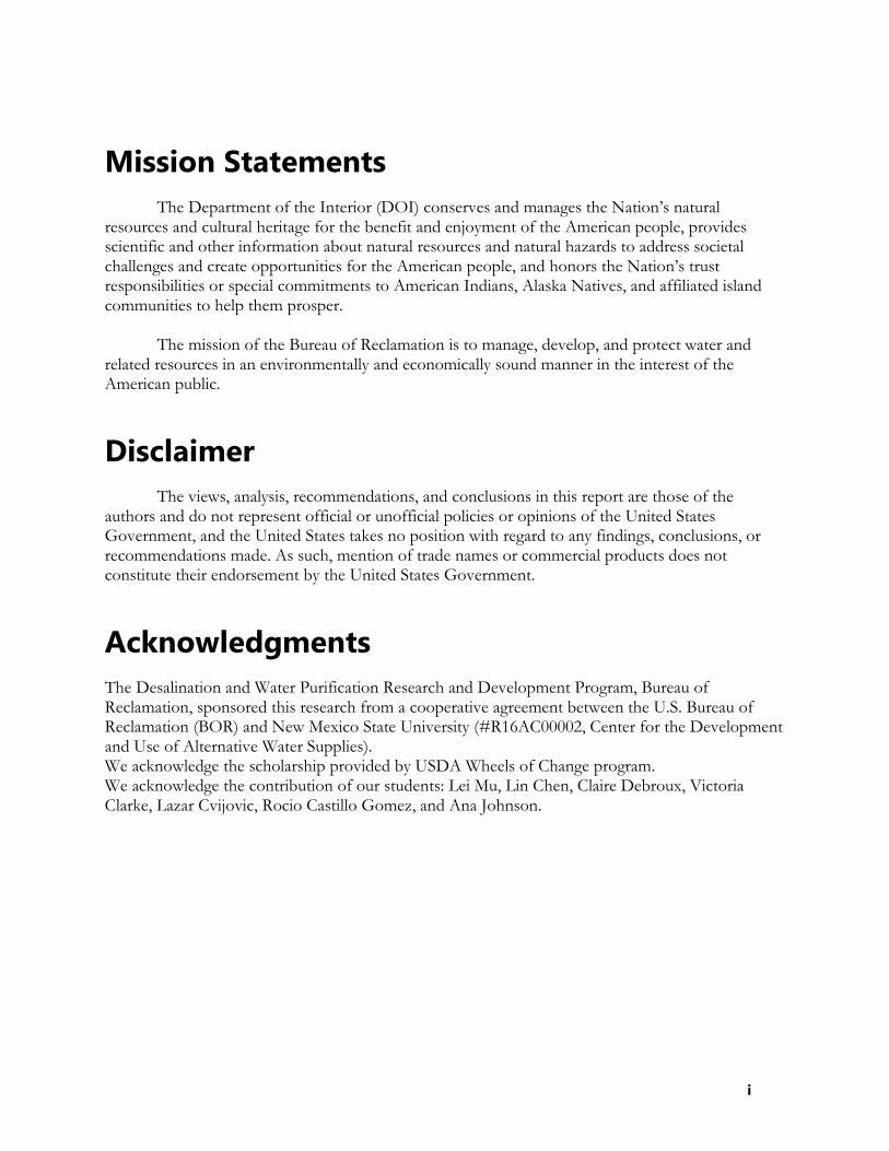
hrs) were similar to each other because the heat was continuously absorbed and localized and was being stored in the CF materials and gradually converted into heat for evaporation. However, the evaporation rate accelerated significantly after four hours because the absorbance- storage-conversion of heat was achieved at steady-state within the CF-carbon felt block. After that, solar radiation was continuously absorbed and converted into heat, and thereby transport of water vapor was stable with both CF and the capillary effect. The evaporation rate of the solar still with CF was 0.19 Liter per square meter per hour (LMH) under the maximum solar radiation of 932 W/m2 , while the evaporation rate without CF was only 0.146 LMH under even a higher maximum solar radiation of 969 W/m2 , showing that the evaporation rate was improved by 30.1% with CF even under a lower solar radiation.
Figure 3-5. Comparison of evaporation rate with and without CF
3.2. Evaporation at Water-vapor Interface Using Photothermal Membranes
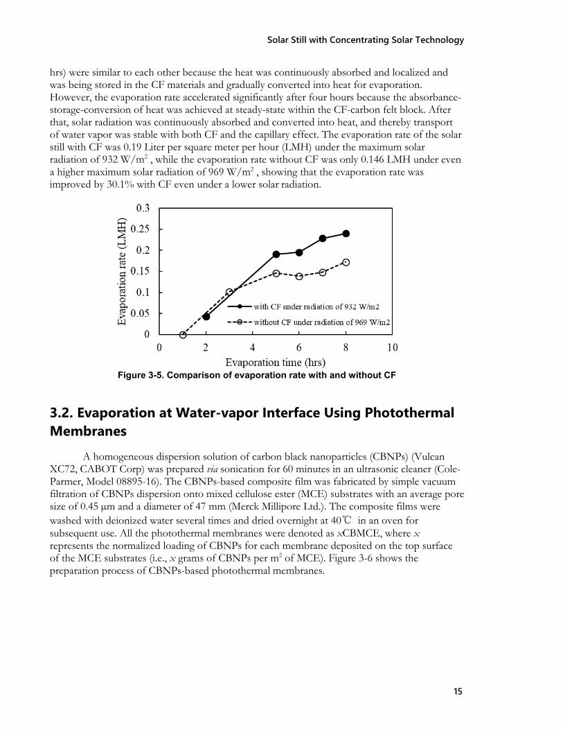
A homogeneous dispersion solution of carbon black nanoparticles (CBNPs) (Vulcan XC72, CABOT Corp) was prepared via sonication for 60 minutes in an ultrasonic cleaner (Cole- Parmer, Model 08895-16). The CBNPs-based composite film was fabricated by simple vacuum filtration of CBNPs dispersion onto mixed cellulose ester (MCE) substrates with an average pore size of 0.45 µm and a diameter of 47 mm (Merck Millipore Ltd.). The composite films were washed with deionized water several times and dried overnight at 40℃ in an oven for subsequent use. All the photothermal membranes were denoted as xCBMCE, where x represents the normalized loading of CBNPs for each membrane deposited on the top surface of the MCE substrates (i.e., x grams of CBNPs per m2 of MCE). Figure 3-6 shows the preparation process of CBNPs-based photothermal membranes.
Solar Still with Concentrating Solar Technology
16
Figure 3-6. Fabrication of CBNPs based photothermal membrane
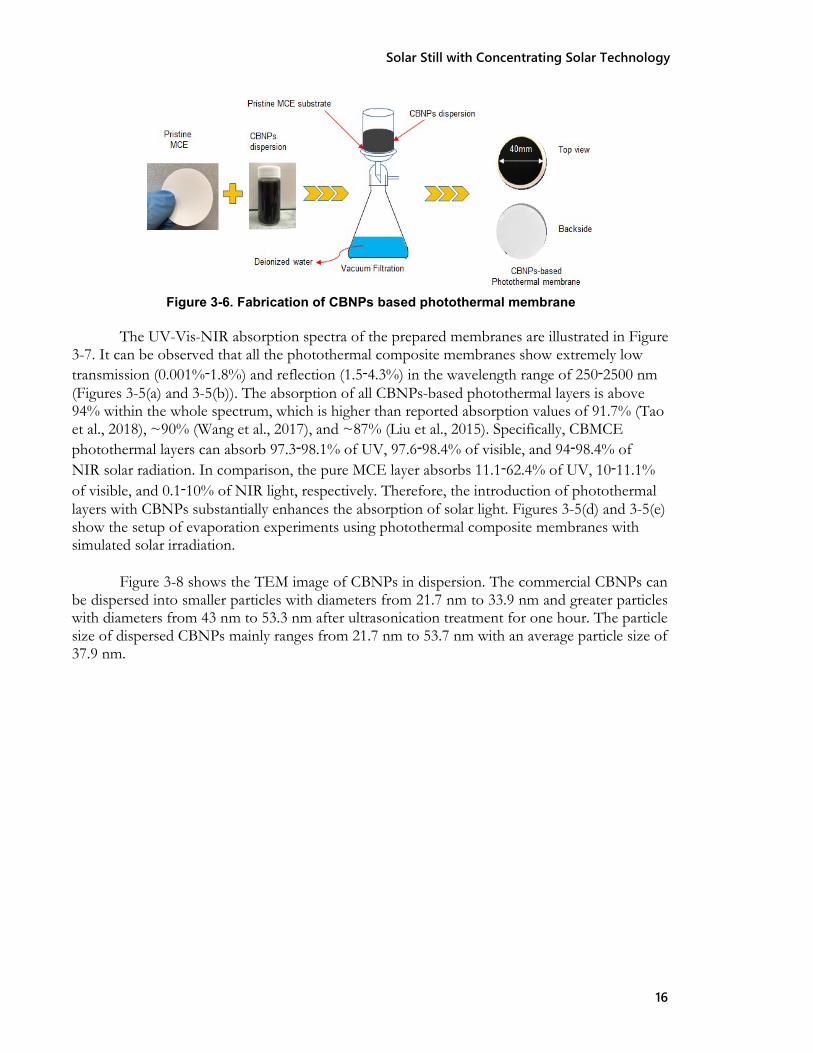
The UV-Vis-NIR absorption spectra of the prepared membranes are illustrated in Figure 3-7. It can be observed that all the photothermal composite membranes show extremely low transmission (0.001%‑1.8%) and reflection (1.5‑4.3%) in the wavelength range of 250‑2500 nm (Figures 3-5(a) and 3-5(b)). The absorption of all CBNPs-based photothermal layers is above 94% within the whole spectrum, which is higher than reported absorption values of 91.7% (Tao et al., 2018), ~90% (Wang et al., 2017), and ~87% (Liu et al., 2015). Specifically, CBMCE photothermal layers can absorb 97.3‑98.1% of UV, 97.6‑98.4% of visible, and 94‑98.4% of NIR solar radiation. In comparison, the pure MCE layer absorbs 11.1‑62.4% of UV, 10‑11.1% of visible, and 0.1‑10% of NIR light, respectively. Therefore, the introduction of photothermal layers with CBNPs substantially enhances the absorption of solar light. Figures 3-5(d) and 3-5(e) show the setup of evaporation experiments using photothermal composite membranes with simulated solar irradiation.
Figure 3-8 shows the TEM image of CBNPs in dispersion. The commercial CBNPs can
be dispersed into smaller particles with diameters from 21.7 nm to 33.9 nm and greater particles with diameters from 43 nm to 53.3 nm after ultrasonication treatment for one hour. The particle size of dispersed CBNPs mainly ranges from 21.7 nm to 53.7 nm with an average particle size of 37.9 nm.

Solar Still with Concentrating Solar Technology
17
Figure 3-7. UV-Vis-NIR absorption spectra of the prepared membranes: (a) Transmission, (b) Reflectance, (c) Absorbance, (d) Set-up of the solar vapor generation system, and (e) Top view
of CBMCE membrane during the evaporation experiments
Figure 3-8. TEM image of CBNPs in dispersion
The surface morphology of the pristine 0.45 µm membrane shows the MCE substrate has a highly porous structure due to the randomly linked and twisted texture of cellulose ester fibers (Figure 3-9(a)). There is no obvious difference between the surface morphology of the five CBMCE membranes (Figures. 3-9(b) to 3-9(f)). The uniform CB photothermal layer on the top surface of the MCE substrate was obtained and the surface pores of the MCE were all

Solar Still with Concentrating Solar Technology
18
covered by the CBNP dispersions filtrated with assistance of a vacuum pump. CBNPs can be easily deposited from CBNP dispersions on the hydrophilic top surface of the MCE substrate because of the hydrophilic nature of the MCE. The thicknesses of the CBNPs layers increased from 1.6, 3.4, 11.1, 19.4, to 32.9 µm, corresponding to 1, 2.5, 5, 12.5, and 25 mg of the loaded CBNPs, respectively.
Figure 3-9. SEM images of top surfaces of (a) pristine MCE, (b) 0.8CBMCE, (c) 2CBMCE, (d) 4CBMCE, (e) 10CBMCE, and (f) 20CBMCE
3.2.1. Key Results Key results are provided in this section. For further details, the readers are requested to
refer to Chen and others, 2020. Figure 3-10 shows the evaporation performance of deionized water and enhancement of evaporation for each membrane sample under 5-suns with a water depth of 9 cm at relative humidity of 54%. The surface temperatures of the control sample (open-water system with no membrane applied) were the lowest during the 1-hour evaporation (from initial room temperature to 46.6℃). The surface temperature curves of all the evaporation cases with photothermal membranes were above the control curve, and the final surface temperatures on the top surface of CBNPs layers exhibited a slight upward trend with the increasing normalized loading of CBNPs. The temperature difference between the enhanced evaporation cases and the control sample ranges from 11.5 to 12.3℃. The average evaporation rate (AER) of the control, 0.8CBMCE, 2CBMCE, 4CBMCE, 10CBMCE, and 20CBMCE samples were 3.1, 3.3, 4.3, 4.4, 5.0, and 4.5 KMH after exposed to simulated 5-suns (5 kW·m-2) solar irradiation for 60 min. Evaporation rates with 0.8CBMCE, 2CBMCE, 4CBMCE, 10CBMCE, and 20CBMCE photothermal composite membranes were enhanced by 6.5%, 38.7%, 41.9%, 61.3%, and 45.2% compared with the control, respectively (Figure 3-10(b)). The corresponding evaporation efficiency of each membrane exhibited the same trend (Figure 3- 10(c)). The maximum AER of 5.0 KMH and evaporation efficiency of 69.3% were achieved using the 10CBMCE membrane. Thus, evaporation performance using the 10CBMCE membrane is the highest among all these photothermal membranes.

Solar Still with Concentrating Solar Technology
19
Figure 3-10. Evaporation performance of deionized water using CBNPs-based photothermal membranes with different normalized loading of CBNPs under 5-suns irradiation at relative humidity of 54%: (a) surface temperature variation with evaporation time, (b) Comparison
To further study the evaporation behavior of CBMCE membranes, we investigated the
evaporation performance of 13.5 wt.% NaCl solution using the 10CBMCE photothermal composite membrane under different solar irradiation densities at a relative humidity of 54%. Evaporation performance without the application of CBMCE membrane (the control) was conducted and the result set the baseline. Figure 3-11 shows the results. The AER of evaporation increased with increasing irradiation power density for both the control and the experiment with the 10CBMCE membrane, which is the same trend reported by other researchers (Finnerty et al., 2017; Liu et al., 2017; Zhou et al., 2016). The AER of evaporation using 10CBMCE under 1, 2, 3.5, 4.5 and 5-suns solar irradiation are 0.6, 1.3, 2.5, 3.5 and 3.8 KMH, which are 1.75, 2.45, 1.73, 1.71 and 1.53 times that of the control experiments under the same solar power density, respectively. The maximum enhancement of evaporation with and without 10CBMCE was achieved under 2-suns solar irradiation. In addition, the AER using 10CBMCE reached the highest enhancement when light intensity was increased from 2-suns to 3.5-suns. The evaporation efficiency using 10CBMCE under 5-suns was 1.53 times that of evaporation without the photothermal membrane. The experimental results demonstrated the use of a black photothermal layer of CBNPs enhanced the solar evaporation performance.
The effects of saline water depth on interfacial evaporation was also studied using 13.5
wt.% NaCl solution under 5-suns solar irradiation at saline water depths of 5, 9, and 13 cm with the 10CBMCE photothermal membrane. Figure 3-12(b) shows the AER and evaporation efficiency using 10CBMCE at different water depths. For water depths of 5, 9, and 13 cm, the AER of saline water under 5-suns irradiation at relative humidity of 54% were 4.4, 3.8, and 3.4 KMH and the evaporation efficiencies 61.7%, 53.9%, and 47.1%, respectively. Therefore, the

Solar Still with Concentrating Solar Technology
20
evaporation performance was enhanced with decreasing water depth when other conditions were kept the same.
Figure 3-11. Comparison of (a) AER and (b) evaporation efficiency performance for evaporation of 13.5 wt.% NaCl solution with water depth of 9 cm under 5-suns radiation at
relative humidity of 54%
Figure 3-12. Evaporation performance of 13.5 wt.% NaCl solution at various water depths under 5-suns irradiation and relative humidity of 54%
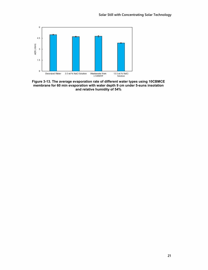
Figure 3-13 shows the AER of different water types using the 10CBMCE photothermal
composite membrane under 5-suns irradiation with a water depth of 9 cm and relative humidity of 54%. The maximum AER of 5.0 KMH was obtained for deionized water, and AER decreased with increasing salinity of the solution. Specifically, the AER of simulated sea water (3.5 wt.% NaCl solution), wastewater (the salinity of ~768 mg/L as total dissolved solids) from LCWWTP, and the 13.5 wt.% NaCl solution were 4.7, 4.8, and 3.8 KMH, respectively. The evaporation rate of water is affected by the aqueous solution composition and the partial vapor pressure, which decreases at higher salinity. This is because the partial vapor pressure of the aqueous mixture was significantly influenced by the mole fraction of the liquid water molecules in the mixture in which mole fraction of water molecules decreases with increasing salinity based on the Raoult’s law (Guggenheim, 1937; Panomwan Na Ayuthaya et al., 2013).
On the other hand, the variation of AER of the liquid water was affected by the bulk
water thermal conductivity. The thermal conductivity of the aqueous NaCl solution decreases with increasing salt concentration (Ozbek and Phillips, 1979). Therefore, AER decreased with increasing salinity. The AER of various water types using the low-cost CBNPs-based photothermal membranes showed potential for practical applications, that is, not only for distillation and desalination of saline water but also for purification of municipal wastewater.
(a) (b)
Solar Still with Concentrating Solar Technology
21
Figure 3-13. The average evaporation rate of different water types using 10CBMCE membrane for 60 min evaporation with water depth 9 cm under 5-suns insolation
and relative humidity of 54%
Solar Still with Concentrating Solar Technology
22
3.3. Evaporation at Basin-water Interface Using Hydrophilic Surfaces
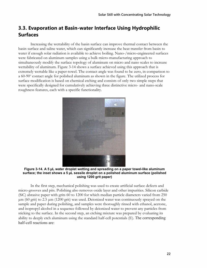
Increasing the wettability of the basin surface can improve thermal contact between the basin surface and saline water, which can significantly increase the heat transfer from basin to water if enough solar radiation is available to achieve boiling. Nano-/micro-engineered surfaces were fabricated on aluminum samples using a bulk micro-manufacturing approach to simultaneously modify the surface topology of aluminum on micro and nano scales to increase wettability of aluminum. Figure 3-14 shows a surface achieved using this approach that is extremely wettable like a paper-towel. The contact angle was found to be zero, in comparison to a 60-90o contact angle for polished aluminum as shown in the figure. The utilized process for surface modification is based on chemical etching and consists of only two simple steps that were specifically designed for cumulatively achieving three distinctive micro- and nano-scale roughness features, each with a specific functionality.
Figure 3-14. A 5 µL water droplet wetting and spreading on a paper towel-like aluminum surface; the inset shows a 5 µL sessile droplet on a polished aluminum surface (polished
using 1200 grit paper)
In the first step, mechanical polishing was used to create artificial surface defects and micro-grooves and pits. Polishing also removes oxide layer and other impurities. Silicon carbide (SiC) abrasive paper with grits 60 to 1200 for which median particle diameters varied from 250 μm (60 grit) to 2.5 μm (1200 grit) was used. Deionized water was continuously sprayed on the sample and paper during polishing, and samples were thoroughly rinsed with ethanol, acetone, and isopropyl alcohol in a sequence followed by deionized water to prevent any particles from sticking to the surface. In the second step, an etching mixture was prepared by evaluating its ability to deeply etch aluminum using the standard half-cell potentials (E). The corresponding half-cell reactions are:

Solar Still with Concentrating Solar Technology
23
NO3−(aq) + 4 H+(aq) + 3e− → NO(g) + 2H2O(l); E = 0.96 V
Al3+(aq) + 3e− → Al(s); E = −1.66 V
Al + 4H+ + NO3− → Al3+ + NO + 2H2O; E0 = (0.96 + 1.66) V = 2.62 V
where the phases are aq (aqueous), l (liquid), g (gas), and s (solid).
The solution used to etch samples was 1:1:4 by volume of deionized water, methanol, and diluted nitric acid (33%). The samples in the solution were heated in an oven at 105o for 90 minutes. A high temperature environment aids in promoting and catalyzing the etching reaction. After the samples were taken out of the oven, they were washed with deionized water and dried by forced convection of air at ambient temperature. During this process poisonous nitrogen dioxide gas can be visually observed as brown fumes.
3.3.1. Experiments and Key Results Most of the surfaces prepared using the above-mentioned process were found to have
zero CA, and the majority of others less then 3o, putting them among the best values reported and obtained through the use of coatings, sintering, and micro-fabrication. Surfaces were observed under a scanning electron microscope (SEM). Generated SEM images (Figure 3-15) revealed micro-grooves and pits that were generated in step 1 along with the nano-cavities inside the embryos of micro-cavities. The cavities were randomly distributed over the surface and ranged in size from less than 100 nm to 10 µm. No other previously reported pure (unetched) aluminum surfaces showed a dual length scale roughness with a CA of zero. Elemental analysis proved the purity of aluminum, showing 98.62% pure aluminum with negligible amounts (<0.5%) of trace elements such as FE and MN, which are part of alloys 6061 and 3035 used for surface treatment.
Figure 3-15. An ultra-omniphilic aluminum surface observed under a SEM under different resolutions (× 37 to × 32,000) and at various locations on the same sample

Solar Still with Concentrating Solar Technology
24
Experiments were performed using the setup shown in Figure 3-16 to compare the performance of the developed boiling surfaces with plain untouched surfaces for various salt concentrations. The experimental setup consisted of an aluminum plate, polycarbonate cylinder, insulated glass funnel, condenser and a container for distillate. The aluminum plate was attached to the cylinder with bolts to form a boiling tank with a boiling surface of about 180 cm2 (28 square inches). A gasket was used to prevent any leaks between the aluminum plate and the cylinder. On the top of the cylinder, an insulated glass funnel was placed to direct the steam into the condenser, which was securely placed at a slope to allow for condensate to drip into the container. A glass funnel was insulated to prevent condensation and the return of evaporated water back into the boiling tank from the walls of the funnel. The performance was measured based on the quality of the distillate produced and the rate of scaling and corrosion on the boiling surface. It was found that though the surfaces showed improvement in water turnover rate by 15-20% compared to boiling on a plain aluminum surface, the corrosion is very high on these surfaces due to the surface roughness.
Figure 3-16. Schematic of the test setup for boiling tests
To address the corrosion issue, special surfaces called binary surfaces are currently being developed. These surfaces were previously developed for copper and showed significant heat transfer performance. During this project, we were able to fabricate these surfaces on aluminum in the available time and with the available resources for the project. Our initial tests showed that these surfaces could aid in reducing corrosion (corrosion reduced by 50% compared to plain surface) and the heat transfer rate improved by 15%, which could be higher for increased heat flux. The methodology used to fabricate these surfaces is shown in Appendix D.

Solar Still with Concentrating Solar Technology
25
4. Enhancing the Condensation Rate
4.1. Superhydrophobic coatings on glass cover Superhydrophobic coating on the glass cover surface was considered a new method to
improve anti-fogging of the glass surface and the condensation of water vapor and collection of fresh water when water evaporates in the solar still. Silica nanoparticles were used in this study for the superhydrophobic coating onto the inner surface of the glass cover of the designed solar still. The impact of coating on the evaporation performance of the different solar stills with different tilting angles was investigated under the same experimental conditions. These stills were fabricated with different glass slope angles to test the performance of the evaporation in these stills before and after coating and to verify the impact of the silica coating on fresh water output. Two solar thermal stills were designed by using double-slope glass covers with tilt angles of 66º and 26º (called as still A and still B, respectively) as shown in Figures 4-1 and 4-2. The thickness of the glass cover of the two stills was 4 mm. The evaporation basin of still A was made of stainless steel, while that of still B was black polycarbonate sheets. The area of the evaporation basins was 588 cm2 and 745 cm2 for stills A and B, respectively. The distillate was collected in a collection container. Tap water was used during the experiments to investigate the performance of these stills under natural solar radiation. During the outdoor tests, the maximum solar radiation for solar still A ranged from 1004 W/m2 to 1035 W/m2, and from 846 W/m2 to 1041 W/m2 for still B. The effects of water cooling on the enhancement of the solar stills was tested using water cooling through a pump at a flow rate of 400 ml/min during evaporation of still B before coating.
Figure 4-1. Solar still A with a tilt angle of 66 degrees

Solar Still with Concentrating Solar Technology
26
Figure 4-2. Two identical solar stills B with a slope angle of 26 degrees in order to compare the
impact of hydrophobic coating
The silica nanoparticles containing solution was prepared by co-hydrolysis and condensation of two silane precursors, tetraethyl orthsilicate (TEOS) and tridecafluoroctyltriethoxysilane (FAS), in an ammonia-ethanol solution. The preparation process of the silica nanoparticle solution was conducted as follows: TEOS (5 ml), together with an appropriate amount of FAS (the best result was obtained when coating on fiber surface with FAS/TEOS ratio = 1 : 10 mol/mol), was dissolved in 25 ml ethanol. The solution was mixed with an ammonium hydroxide/ethanol solution (6 ml 28% NH3·H2O in 25 ml ethanol), and stirred intensively at room temperature for 12 hours. The milky mixture solution was then ultrasonicated for 30 minutes to produce a homogeneous suspension prior to coating the solution onto the substrates. Upon drying at room temperature, the treated substrate was further cured at 110ºC for one hour. Figures 4-3 and 4-4 show the prepared silica nanoparticle solution and resulted superhydrophobic coating on glass slides.
Figure 4-3. Preparation of coating solution
without coating
with silica coating

Solar Still with Concentrating Solar Technology
27
Figure 4-4. Coating on glass slides
Hydrophobicity of the modified surface of the glass is determined by the water contact angle (CA), which was determined by contact measured by a goniometer (NRL C.A. Goniometer 100-00-115, ramé-hart instrument co.). CA was determined by calculating the average value of all the sums of the recorded advancing and receding contact angles of five droplets with the same volume of 5 μL for each drop. Turbidity was measured by a LaMotte 2020t Turbidity Meter.
4.1.1. Key Results Figure 4-5 shows that the average output and maximum hourly yield of still A without and with silica coating are 2.8 L/m2/day and 1.8 L/m2/day and 51 ml/hr and 20 ml/hr, respectively. The results illustrate that both average output and maximum hourly yield are higher without the silica coating than with the silica coating. The results indicated that output from a non-coated solar still A was 55% higher than the case with silica coating.
Figure 4-5. Average fresh water output and maximum hourly yield of still A with and without silica coating
Figure 4-6 illustrates the results of solar still B before and after silica coating. The distillate output before coated with silica nanoparticles was higher than after under different maximum daily solar radiations. And the distillate output of still B before silica coating increased with the maximum daily solar radiation. However, this trend was not observed when coated with silica nanoparticles. The yield of still B without silica coating was almost 48% to 64% higher than that

Solar Still with Concentrating Solar Technology
28
with silica coating. This result indicated that coating may decrease the performance of the still due to reduced light transmittance and condensation of water vapor.
80
60
40
20
0 846
968
1035
1041
Maximum daily solar radiation (W/m2)
Figure 4-6. Distillate output of still B before and after silica coating
Figure 4-7 shows the difference of distillate output of still B with and without water cooling before silica coating. Water film cooling with water flow rate of 400 ml/min increased the distillate output by 78.2%.
90
75
60
45
30 no cooling water cooling
Figure 4-7. Effect of cooling on distillate output of still B (water flow rate is 400 ml/min)
From the results, it can be concluded that silica hydrophobic on the glass cover surface may be of no benefit for enhancing evaporation. Both average output and maximum hourly yield of fresh water for the uncoated still is higher than for the coated still using silica nanoparticles. This trend is much more apparent for the maximum hourly yield. These results may be attributed mainly to the reduction of solar radiation and heat transfer of the coated glass cover due to the existence of a very thin layer (or film) of hydrophobic silica coating. Further details of experiments and results obtained under this task are shown in Appendix E.
before coating after coating
55 59
46 52
35 37 28
33
Dis
tilla
te o
utpu
t (m
l/m2 /h
r)
Dis
tilla
te o
utpu
t (m
l/m2 /h
r) 82
46

Solar Still with Concentrating Solar Technology
29
5. Economic Analysis Since we were able to achieve significant improvements with the Fresnel lens and
interfacial evaporation materials, we conducted preliminary economic analysis of these enhancements. A more thorough analysis and results are needed to perform the economic analysis of basin-water interface enhancement and condensation enhancement. This analysis will be performed once the methodologies are optimized in our next project.
5.1 Solar Still with Fresnel Lens The economic performance of the desalination system (with Fresnel lens (FRL)) was
evaluated by calculating the cost of purified water per liter, which depends on the annual fixed cost, the annual cost on system maintenance and operation, recovery factor, the annual salvage value, and the annual fresh water yield (MacDonald, 2010). For the current calculations, the fixed cost of the system with FRL is around $325, whereas without FRL it is around $199. For calculation of the recovery factor, a 3% interest and 10 years lifetime was assumed. The annual maintenance costs, which mainly includes the costs of regular water filling, fresh water collecting, and the cleaning of the system, was assumed to be 30% of annual fixed costs. Since the system daily yield varies with respect to season, weather conditions, operation parameters, and so on, an average yield was calculated using the methodology described by Pakdel and others (2017). The system daily yields with and without FRL were considered to be 1.625 L/m2 and 9.22 L/m2, respectively, as experimentally measured in Section 3.1. By assuming that desalination systems operate for 340 days in one year, the average annual yield was calculated to be 552.5 L/m2 and 3134.8 L/m2. Table 5-1 shows the results. Although the introduction of FRL increased the fixed cost, the cost of purified water decreased significantly due to the increased evaporation rate. It should be noted that the cost estimates are based on the results obtained in the experiments. If the concentration ratio is higher and the amount of water produced increases, and/or a larger scale system is considered, this cost could be lower.
Table 5-1. Cost comparison between different solar still configurations based on results obtained Different configurations of solar still
Annual yield (L/m2)
Fixed cost ($)
Annual fixed cost ($)
Annual Salvage Value ($)
Annual Maintenance Cost ($)
Cost of purified water per liter ($/L-m2)
Without Fresnel lens 552.5 199 23.3 3.47 6.99 0.049
With Fresnel lens 3134.8 325 38.1 5.67 11.43 0.014

Solar Still with Concentrating Solar Technology
30
5.2 Solar Still with Fresnel Lens and Interfacial Evaporation Materials
The economic benefit of the carbon black nanoparticles (CBNPs) based interfacial nanocomposite films (INF) enhanced evaporation is evaluated based on the evaporation performance in a solar still. In the southwestern United States, approximately 30 liters of clean water per day are typically required for a household of four people for drinking and cooking. For an evaporation of 13.5 wt.% NaCl solution, the INF achieved an average evaporation rate (AER) of ~4.4 kilograms per m2 per hour with water depth of 5 cm. Thus, an evaporation area of 1 m2 is required to produce an adequate amount of clean water for drinking and cooking to meet the needs of an average household. The costs are calculated by adding the costs for consumable materials and fixed costs. Consumable costs includes the cost of CBNPs and MCE. Fixed costs refer to the cost of the wood frame (solar still walls), metal basin, glass cover and FRL (solar concentrator). For an effective evaporation area of 1 m2 INF, the estimated amount of CBNPs required is 10 g at a cost of $1.54. For the cost estimate, it is assumed the solar radiation time is eight hours per day, the average sunny days are 294 days per year in Las Cruces, New Mexico, the lifetime of the INF is five years (typical lifespan of the mixed cellulose ester (MCE)substrates), and the typical lifetime of a solar still (the fixed materials) is ten years. The bulk commercial prices of main materials are summarized in Table 5-2.
Table 5-2. Cost estimate of materials for a 1 m2 solar still
Materials Commercial size Overall price ($) Unit price ($) CBNPs 100 g 15.37 0.1537/g
MCE 100 m2/roll 1260 12.6/m2
Total consumable cost
$14.14/m2 *
Wood frame 1220 mm×2440 mm×18 mm 40 20/pc Glass cover 1m × 2m × 3mm 80 40/m2
Stainless steel basin 1m × 2m × 1mm 46.51 23.25/m2
Fresnel lens 1100 mm ×1100 mm $50/pc Total fixed cost $216.51 for a solar still
* $14.14/m2 is the normalized cost per m2 of effective evaporation area.
Table 5-3 shows the cost estimate per m3 of clean water generated assuming different sun concentrations. The total cost of a solar still with the evaporation area of 1 m2 is estimated to be $245 with a lifetime of ten years. The estimated life cycle cost of desalting high salinity water (13.5 wt.% NaCl in this study) using an INF-enhanced solar still is approximately $8 per m3 of clean water generated as shown in the table when it is assumed that we can obtain around 2-suns concentration. For this case, the cost per liter per m2 is $0.00057/L-m2, assuming FRL can increase the concentration by 2-suns. When 1-sun is considered, the life cycle cost for this enhancement technique is $0.012/L-m2. It should be noted that these estimations were performed assuming a large-scale system.

Solar Still with Concentrating Solar Technology
31
Table 5-3. Life cycle cost of a solar still to treat 13.5% saline water for clean water production Consumable materials
(INF) Fixed materials
Lifetime of materials (years) 5 10
Lifetime of solar still (years) 10 Total materials costs (including replacement of INF)
$28.28 $216.51
Total cost of solar still $244.79 Annual clean water yield 3.06 m3 (2 suns), 1.41 m3 (1 sun), Life cycle cost per m3 clean water ($/m3) 8.00 (insolation- 2 suns), 17.36 (insolation- 1 sun) Life cycle cost per liter clean water ($/L-m2) 0.00057 (2 suns), 0.012 (1 sun)
Current industrial standard desalination processes such as reverse osmosis usually require intensive capital investment and access to an electrical grid to meet high energy demand. The INF-enhanced solar evaporation system is a promising technology and has the potential for practical application especially in remote and arid regions with abundant solar energy and/or no access to an electrical grid.

Solar Still with Concentrating Solar Technology
32
6. Conclusions
6.1. Conclusions
The key conclusions from the current project are: 1. The test with the FRL concentrating system showed a water output increase of 467%. 2. Using hydrophobic coatings may not enhance the condensation on glass. 3. The evaporation efficiency using 10CBMCE under 5-suns was 1.53 times that of
evaporation without the photothermal membrane. CBNPs-based photothermal membranes showed considerable potential for practical application not only for distillation and desalination of saline water, but also for the purification of municipal wastewater.
4. Binary surfaces can aid in enhancing boiling and reducing corrosion. 5. The cost of water decreased from 0.049 L/m2 to 0.014 L/m2 when an external FRL was
used, based on the results obtained while testing. This number could be different when seasonal performance is considered along with scale-up applications.
6.2. Recommended Next Steps The results of this project show the potential for achieving rapid heat transfer rates in solar stills that can be a scalable and viable option for desalination in arid and semi-arid regions. Each of the techniques developed under this project are not only useful for the proposed solar still, but can be coupled with other applications as well. The proposed solar enhancement techniques can be useful for enhancing the solar input to not only solar stills but also other thermal distillation techniques. Photothermal membranes and interfacial membranes could be used for solar stills, solar ponds, and other related water purification systems. Binary surfaces could be useful for reducing corrosion in all thermal distillation applications. The results from this project will be useful for novel thermal desalination systems design. The individual scale-up potential of each of the techniques could be further explored in a pilot-scale system. In our next project, the scale-up potential of these techniques and the combined efficiency at a larger scale will be demonstrated. Please see Appendix A for details of the project.

Solar Still with Concentrating Solar Technology
33
7. References
Agrawal, A., Rana, R., Srivastava, P.K., 2017. Heat transfer coefficients and productivity of a single slope single basin solar still in Indian climatic condition: Experimental and theoretical comparison. Resource-Efficient Technologies 3, 466-482.
Badruzzaman, M., Oppenheimer, J., Adham, S., Kumar, M., 2009. Innovative beneficial reuse of reverse osmosis concentrate using bipolar membrane electrodialysis and electrochlorination processes. J Membrane Sci 326, 392-399.
Beckman, J.R., 2008. Dewvaporation desalination 5,000-gallon-per-day pilot plant. Desalination & Water Purification Research & Development Program Report No. 120.
Bond, R., Batchelor, B., Davis, T., Klayman, B., 2011. Zero liquid discharge desalination of brackish water with an innovative form of electrodialysis metathesis. Florida Water Resources Journal 2011, 38-44.
Chen, L., Wang, H., Kuravi, S., Kota, K., Park, Y.H., Xu, P., 2020. Low-cost and reusable carbon black based solar evaporator for effective water desalination. Desalination 483, 114412.
Davis, T.A., 2006. Zero discharge seawater desalination: Integrating the production of freshwater, salt, magnesium, and bromine. Desalination & Water Purification Research & Development Program Report No. 111.
Dunkle, R., 1961. Solar water distillation: the roof type still and a multiple effect diffusion still, Proc. International Heat Transfer Conference, University of Colorado, USA, p. 895.
Durkaieswaran, P., Murugavel, K.K., 2015. Various special designs of single basin passive solar still–A review. Renew Sust Energ Rev 49, 1048-1060.
Finnerty, C., Zhang, L., Sedlak, D.L., Nelson, K.L., Mi, B., 2017. Synthetic graphene oxide leaf for solar desalination with zero liquid discharge. Environ Sci Technol 51, 11701-11709.
Gabelich, C.J., Williams, M.D., Rahardianto, A., Franklin, J.C., Cohen, Y., 2007. High-recovery reverse osmosis desalination using intermediate chemical demineralization. Journal of Membrane Science 301, 131-141.
Gude, V.G., Nirmalakhandan, N., Deng, S.G., 2011. Desalination using solar energy: Towards sustainability. Energy 36, 78-85.
Guggenheim, E.A., 1937. The theoretical basis of Raoult's law. Transactions of the Faraday Society 33.

Solar Still with Concentrating Solar Technology
34
Hasnain, S.M., Alajlan, S.A., 1998. Coupling of PV-powered RO brackish water desalination plant with solar stills. Desalination 116:1:57-64.
Johnson, A., Mu, L., Park, Y. H., Valles, D. J., Wang, H., Xu, P., Kuravi, S., 2019. A thermal model for predicting the performance of a solar still with Fresnel lens. Water 11:9:1860.
Kabeel, A., Omara, Z., Younes, M., 2015. Techniques used to improve the performance of the stepped solar still—A review. Renew Sust Energ Rev 46, 178-188.
Kaviti, A.K., Yadav, A., Shukla, A., 2016. Inclined solar still designs: A review. Renew Sust Energ Rev 54, 429-451.
Kumar, P.V., Kumar, A., Prakash, O., Kaviti, A.K., 2015. Solar stills system design: A review. Renew Sust Energ Rev 51, 153-181.
Liu, Y., Yu, S., Feng, R., Bernard, A., Liu, Y., Zhang, Y., Duan, H., Shang, W., Tao, P., Song, C., Deng, T., 2015. A bioinspired, reusable, paper-based system for high-performance large-scale evaporation. Adv Mater 27, 2768-2774.
Liu, Z., Song, H., Ji, D., Li, C., Cheney, A., Liu, Y., Zhang, N., Zeng, X., Chen, B., Gao, J., Li, Y., Liu, X., Aga, D., Jiang, S., Yu, Z., Gan, Q., 2017. Extremely cost-effective and efficient solar vapor generation under nonconcentrated illumination using thermally isolated black paper. Global Challenges 1, 1600003.
Lozier, J.C., Erdal, U.G., Lynch, A.F., Schindler, S., 2007. Evaluating traditional and innovative concentrate treatment and disposal methods for water recycling at Big Bear Valley, California. CH2M Hill report.
MacDonald, G.M., 2010. Water, climate change, and sustainability in the southwest. Proceedings of the National Academy of Sciences 107, 21256-21262.
Martinetti, C.R., Childress, A.E., Cath, T.Y., 2009. High recovery of concentrated RO brines using forward osmosis and membrane distillation. Journal of Membrane Science 331, 31-39.
Mickley, M.J., 2009. Treatment of Concentrate, Desalination and Water Purification Research and Development Program Report No. 155.
Mu, L., Xu, X., Williams, T., Debroux, C., Gomez, R. C., Park, Y. H., Kuravi, S., 2019. Enhancing the performance of a single-basin single-slope solar still by using Fresnel lens: Experimental study. Journal of Cleaner Production, 239, 118094.
Nayi, K.H., Modi, K.V., 2018. Pyramid solar still: A comprehensive review. Renew Sust Energ Rev 81, 136-148.
Ni, G., Zandavi, S.H., Javid, S.M., Boriskina, S.V., Cooper, T.A., Chen, G., 2018. A salt-rejecting floating solar still for low-cost desalination. Energ Environ Sci 11, 1510-1519.

Solar Still with Concentrating Solar Technology
35
Omara, Z.M., Kabeel, A.E., Abdullah, A.S., 2017. A review of solar still performance with reflectors. Renew Sust Energ Rev 68, 638-649.
Ozbek, H., Phillips, S.L., 1980. Thermal conductivity of aqueous NaCl solutions from 20°C to 330°C. Journal of Chemical and Engineering Data 25.3 (1980): 263-267.
Pakdel, M.A., Hedayatizadeh, M., Tabatabaei, S.M., Niknia, N., 2017. An experimental study of a single-slope solar still with innovative side-troughs under natural circulation mode. Desalination 422, 174-181.
Panomwan Na Ayuthaya, R., Namprakai, P., Ampun, W., 2013. The thermal performance of an ethanol solar still with fin plate to increase productivity. Renewable Energy 54, 227-234.
Rahardianto, A., McCool, B.C., Cohen, Y., 2010. Accelerated desupersaturation of reverse osmosis concentrate by chemically-enhanced seeded precipitation. Desalination 264, 256-267.
Ravizky, A., Nadav, N., 2007. Salt production by the evaporation of SWRO brine in Eilat: a success story. Desalination 205, 374-379.
Reahl, E.R., 1992. Waste control – reclaiming reverse osmosis wastewater. Industrial Water Treatment 1992, 36-39.
Rufuss, D.D.W., Iniyan, S., Suganthi, L., Davies, P.A., 2016. Solar stills: A comprehensive review of designs, performance and material advances. Renew Sust Energ Rev 63, 464-496.
Sethi, S., Walker, S., Xu, P., Drewes, J.E., 2009. Desalination Product water recovery and concentrate minimization. Water Research Foundation, Denver, Colo.
Sharshir, S., Elsheikh, A., Peng, G., Yang, N., El-Samadony, M., Kabeel, A., 2017. Thermal performance and exergy analysis of solar stills–A review. Renewable Sustainable Energy Reviews 73, 521-544.
Sivakumar, V., Sundaram, E.G., 2013. Improvement techniques of solar still efficiency: A review. Renew Sust Energ Rev 28, 246-264.
Tao, F., Zhang, Y., Yin, K., Cao, S., Chang, X., Lei, Y., Wang, D., Fan, R., Dong, L., Yin, Y., Chen, X., 2018. A plasmonic interfacial evaporator for high-efficiency solar vapor generation. Sustainable Energy & Fuels 2, 2762-2769.
Velmurugan, V., Mandlin, J., Stalin, B., Srithar, K., 2009. Augmentation of saline streams in solar stills integrating with a mini solar pond. Desalination 249, 143-149.
Wang, X., He, Y., Liu, X., Cheng, G., Zhu, J., 2017. Solar steam generation through bio-inspired interface heating of broadband-absorbing plasmonic membranes. Applied Energy 195, 414-425.
Xiao, G., Wang, X., Ni, M., Wang, F., Zhu, W., Luo, Z., Cen, K., 2013. A review on solar stills for brine desalination. Appl Energ 103, 642-652.
Solar Still with Concentrating Solar Technology
36
Xu, P., Cath, T.Y., Robertson, A.P., Reinhard, M., Leckie, J.O., Drewes, J.E., 2013. Critical review of desalination concentrate management, treatment and beneficial use. Environ Eng Sci 30, 502-514.
Zanganeh, P., Goharrizi, A.S., Ayatollahi, S., Feilizadeh, M.J.D., 2019. Productivity enhancement of solar stills by nano-coating of condensing surface. Desalination 454, 1-9.
Zhang, Y., Ghyselbrecht, K., Meesschaert, B., Pinoy, L., Van der Bruggen, B., 2011. Electrodialysis on RO concentrate to improve water recovery in wastewater reclamation. Journal of Membrane Science 378, 101-110.
Zhang, Y., Ghyselbrecht, K., Vanherpe, R., Meesschaert, B., Pinoy, L., Van der Bruggen, B., 2012. RO concentrate minimization by electrodialysis: Techno-economic analysis and environmental concerns. Journal of Environmental Management 107, 28-36.
Zhou, L., Tan, Y., Wang, J., Xu, W., Yuan, Y., Cai, W., Zhu, S., Zhu, J., 2016. 3D self-assembly of aluminium nanoparticles for plasmon-enhanced solar desalination. Nature Photonics 10, 393- 398.

Solar Still with Concentrating Solar Technology
37
Appendix - A: Products
Products:
Papers published/In preparation 1. Mu, L., Xu, X., Williams, T., Debroux, C., Gomez, R. C., Park, Y. H., Kuravi, S. 2019.
Enhancing the performance of a single-basin single-slope solar still by using Fresnel lens: Experimental study. Journal of Cleaner Production, 239, 118094.
2. Johnson, A., Mu, L., Park, Y. H., Valles, D. J., Wang, H., Xu, P., Kuravi, S. 2019. A thermal model for predicting the performance of a solar still with Fresnel lens. Water, 11:9:1860
3. Chen, L., Wang, H., Kuravi, S., Kota, K., Park, Y.H., Xu, P., 2020. Low-cost and reusable carbon black based solar evaporator for effective water desalination. Desalination 483, 114412.
4. A comprehensive review on designs, performance enhancements, and material and structure advances for solar stills. Renewable and Sustainable Energy Reviews (in preparation)
5. Castillo-Gomez, R., Johnson, A., Mu, L., Park, Y. H., Valles, D. J., Wang, H., Xu, P., Kuravi, S. 2019. Effect of geographic location on the performance of a single-slope solar still. Desalination and Water Treatment (in preparation)
6. Prasad Ram, Krishna Kota, Huyiyao Wang, Pei Xu, Young Ho Park, Sarada Kuravi, Binary surfaces for enhancing boiling processes in desalination, Desalination (in preparation, work on this paper is also supported by USBR under agreement number R19AC00110)
Poster Presentations 1. R. Gomez, Young Ho Park, Delia Valles, Sarada Kuravi, “Analysis of a Modified Solar
Still with Linear Fresnel Lens for Increased Heat Input,” Conference of Society of Hispanic Professional Engineers, SHPE National Conference 2018, Cleveland, OH.
2. Thomas Williams, Claire Debroux, Mirka Holguin, Matthew Lucero, Rocio Castillo- Gomez, Lei Mu, Young Ho Park, Delia Valles, Sarada Kuravi, “Solar Still Modified with Linear Fresnel Lens for Increased Solar Input,” NM AMP Conference 2018, Las Cruces, NM.
3. Lei Mu, Thomas Williams, Claire Debroux, Kami Ruebush, Mirka Holguin, Rocio Castillo-Gomez, Young-Ho Park, Krishna Kota, Pei Xu, Huiyao Wang and Sarada Kuravi, “Effect of Fresnel lens on the performance of a single-basin single-slope solar still,” NM WRRI Conference 2018, Las Cruces, NM.
MS Thesis 1. Theoretical Analysis of a Solar Still, Rocio Castillo Gomez, December 2018

Solar Still with Concentrating Solar Technology
38
2. Considerations for the Pool Boiling of Water on Binary Surfaces, Lazar Cijovic, May 2019
3. Analysis of a Single Slope Solar Still: A Theoretical Approach Using Matlab, Ana Johnson, August 2019
Students Two Ph.D. students and four undergraduate research assistants were funded through this project. Three MS students have graduated based on the work performed under this project. Around 35 Capstone students participated in this project during various semesters.
Proposals Funded A proposal submitted to the USBR based on the results obtained in this project has been funded. The project began on March 1, 2020, which allows us to continue working on the development of the proposed novel solar still. Project Title: Enhanced Solar Desalination Using Innovative Approaches for Concentrate Treatment Total Award Period Covered: 03/01/2020 – 08/30/2021 Total Award Amount: $299,947

Solar Still with Concentrating Solar Technology
39
Appendix - B: Double-Slope Solar Still
Experimental Setup Figure B-1 shows the design of the double-slope solar still that was fabricated. The
prototype was made with glass, plastic, aluminum, epoxy, and other materials. The double-slope glass cover allows the solar still to receive radiation directly from the sun, or parabolic mirrors, or Fresnel lenses. The concentrate/brackish water was fed into the aluminum pan. The condensed droplets were collected into a spillage plastic clear pan. Table B-1 shows the specifications of each of the components used. Tests with this still showed that this initial design has some issues with leakage, reduced transparency at the intersection of both glasses, and high heat loss.
Figure B-1. Initial design for the fabricated solar still
Table B-1: Component Specifications of the Double Slope Solar Still
Component Specifications Heating pan 0.0762 m x 0.3048 m x 0.3048 m; Aluminum Basin pan 0.2032 m x 0.4572 m x 0.9144 m; Plastic Rectangular Glass 0.27559 m x 0.3048 m x 3.175 mm Glass triangular 0.3175 m x 0.5207 m x 3.175 mm Mini float valve (Actuator) 1/4 drive barbed Piping 6.25 mm; Clear PVC Sealant Clear Food Grade Silicone Sealant
Figure B-2 shows the fabricated still along with the Fresnel lens (FRL). The FRL used
for the experiments is 0.635 m x 1.143 m and was held 0.8001 m from the ground using a structure, as shown in Figure B-2. The aluminum pan was filled with saltwater and placed inside the base pan, which was covered with the glass covers. The condensate slides down the glass covers and is collected in the basin pan. This water is later collected and measured. The preliminary tests with the initial setup were performed to evaluate the design and estimate the water output with and without solar enhancement techniques. A total of five

Solar Still with Concentrating Solar Technology
40
tests were performed, three experiments without FRL, and two experiments with FRL. The solar still was tested twice a week for three hours, from 12:30 pm to 3:30 pm. Temperatures were measured during each test at various locations, as noted on the still shown in Figure B- 3. Thermocouples were attached in eight different places (not including measurements of the ambient air temperature). Thermocouples were placed on the outer side and inner sides of the roof, the suspended air inside the still, the water temperature, the back wall, the collection basin, on the insulation, on the box holding the saltwater, and in the ambient air. Temperatures were measured every 15 minutes. Thermocouple readers were used to measure the temperature, and the collected data were manually inputted into an Excel spreadsheet. During experiments, the still was slightly rotated when needed to allow for maximum sun insolation.
Figure B-2. Solar still test setup with Fresnel lens
Figure B-3. Thermocouple locations

Solar Still with Concentrating Solar Technology
41
Results Temperature measurements for all five tests are shown in Figures B-4 to B-8. It can be
observed from the figures that the still temperatures are higher with the presence of FRL as expected. Table B-2 summarizes the collected water output in each of the tests, and the average ambient and glass cover temperatures. It can be seen that the presence of FRL increased the water output by around 778%.
Figure B-4. Measured temperatures at different locations in the still: Experiment #1
Figure B-5. Measured temperatures at different locations in the still: Experiment #2

Solar Still with Concentrating Solar Technology
42
Figure B-6. Measured temperatures at different locations in the still: Experiment 3
Figure B-7. Measured temperatures at different locations in the still: Experiment #4

Solar Still with Concentrating Solar Technology
43
Figure B-8. Measured temperatures at different locations in the still: Experiment #5
Table B-2 Key test results Experiment
No. Enhanced solar
insolation Average ambient
temperature (°C)
Average glass temperature
(°C)
Water output for 3 hours
(mL) 1 No 32.17 48.52 82 2 No 32.02 43.01 41 3 No 33.41 41.75 51 4 Yes 33.47 61.58 397 5 Yes 31.52 85.00 450
Though the fabricated still could provide information on temperatures that can be reached
and condensate output, it was found that the current design had some disadvantages: • Part of the condensate that was collected in the basin pan was re-evaporated and
reduced the performance of the still. This difference was higher when the solar enhancement technique was employed.
• The insulation used could not withstand the high temperatures that were encountered when FRL was used.
• When FRL was used, there was an area on the glass with no condensate (Figure B-9). It can be inferred that using a cooling mechanism is essential and must be considered when FRL is used.

Solar Still with Concentrating Solar Technology
44
Figure B-9. Condensation on the glass cover when Fresnel lens was used

Solar Still with Concentrating Solar Technology
45
Appendix - C: Centralized Mirror Technique A new centralized mirror technique and design was also pursued under this project. For
this approach, our efforts were focused on designing a lab-scale system that could be scaled up and down by changing the number of mirrors used.
Solar Field Design The designed lab-scale experimental platform has three key functional units: 1) heliostat
field (about 16 heliostats); 2) central mirror (hyperbolic surface); and a 3) solar still. Since the solar location is not fixed during the daytime, each heliostat on the ground is
integrated with a tracking capability, which allows the heliostat to track the sun and reflect the sunlight to a fixed point (the upper focal point of the hyperbolic central mirror).
The central mirror has been designed to have a hyperbolic geometry. This design will allow the incident sunlight from each heliostat to further reflect onto the lower focal point of the hyperbolic surface, on which a solar still is located.
A multi-effect solar still has been fabricated that can be used to reuse the latent heat and further boost the purified water production and also enable better condensation.
System Advisor Model (SAM) software was used for the heliostat field design according to
the meteorological condition of Las Cruces, NM, USA. Figure C-1 shows the resultant heliostat field yielded by the SAM software. According to this design, the sunlight can be reflected by ground mirrors to a receiver, which is a convex mirror component of the targeted water desalination system design. Figure C-2 shows the key dimensions that are used for the experimental setup.
The dimensions shown in Figure C-1 were scaled down for the targeted solar desalination
system. Since the convex mirror should be able to further reflect the collected sunlight by ground mirrors to a fixed point on the ground, where a solar still is placed, a hyperbolic geometry was adopted for the convex mirror. The finalized optical design prototype is shown in Figure C-2. Note that the blue dashed and solid curves in Figure C-2 stand for the lower and upper branches of the hyperbolic curve, respectively. The solid black dots are their focal points. With the help of this optical design, the sunlight is reflected by ground mirrors to the upper focal point and subsequently reflected to the lower focal point.
Solar tracker design Each solar tracker works independently and reflects sunlight to the upper focal point
during the entire testing duration. An azimuth-elevation sun-tracking method was adapted for each solar tracker, because this method has been widely used for heliostat applications, as shown in Figure C-3. Each tracker has two rotation shafts, namely an elevation shaft and an azimuth shaft.

Solar Still with Concentrating Solar Technology
46
Figure C-1. An applicable optical design for a concentrated solar power plant located in Las Cruces, NM, USA (courtesy: SAM software)
For the lab-scale setup, two servo motors were used for each tracker for controlling the rotation movements of the elevation shaft and the azimuth shaft (Figure C-4). Commercially available components were used for the fabrication. Functions for the tracking angle of the heliostat have been derived and were used for controlling the tracker. By considering the relative location between each ground mirror and the first focal of the hyperbolic mirror, the function for the tracking angle of each heliostat can be derived, and these are used to determine the tracking direction of each ground mirror. This method can be used to easily determine the normal direction of each heliostat just by inputting independent variables, such as local time, height of the first focus, and coordinates of each heliostat, into the developed functions. This developed model can also be used for a solar field design in the future.

Solar Still with Concentrating Solar Technology
47
Figure C-2. Finalized optical design for the prototype
Figure C-3. Heliostat field design; azimuth-elevation sun-tracking method (courtesy: SAM software)

Solar Still with Concentrating Solar Technology
48
Figure C-4. A fabricated solar tracker. (length × width of the structure: 0.33 × 0.25 m; length ×
width of the mirror: 0.20 × 0.14 m)
Convex mirror design
A hyperbolic curve was designed using the hyperbolic curve equation:
with units of mm, as shown in Figure C-5. The mirror structure was fabricated using 3D printing. The designed mirror structure for 3D printing is shown in Figure C-6. A thin reflective film was then adhered onto the curved surface of the printed mirror structure. Since the designed convex mirror is too big for a 3D print machine, the entire structure was subdivided into nine pieces, and then assembled. The fabricated convex mirror is shown in Figure C-6.
Figure C-5. Convex mirror design

Solar Still with Concentrating Solar Technology
49
Figure C-6. Finished convex mirror
The entire experimental configuration comprises three parts, namely the roof, base, and testing platform. The roof in the center supports the convex mirror; 12 trackers mirrors (mirror size: 0.20 × 0.14 m) are placed on the base; and the testing platform is a black wood sheet with an adjustable height. The entire system is shown in Figure C-7.
Figure C-7. Experimental configuration

Solar Still with Concentrating Solar Technology
50
Preliminary Tests Two tests were conducted to estimate the effectiveness of the proposed optical design in
terms of solar power concentration. Two tests were performed at an NMSU parking lot (32.28 °N, 106.75 °E) on 12/13/2019 and 12/21/2019 by varying the distance between the testing base and the roof. Both days were sunny with clear skies. The testing platform was located 0.4 m high above the base on both days. The distance between the base and the roof was about 1.5 m on 12/13/2019 and was decreased to 0.85 m on 12/21/2019. The photos of these two tests are given in Figure C-8.
(a) (b)
Figure C-8. Photos taken during tests: (a) 12/13/2019; (b) 12/21/2019
Solar radiation was measured in both the tests from 12:00 pm to 3:00 pm to estimate the amount of solar enhancement when the mirrors were used. During each experiment, solar radiation (W/m2) was recorded every 15 minutes at nine different locations on the testing platform; meanwhile, the direction of ground mirrors was adjusted at the same frequency (after each data acquisition), so that the sunlight was concentrated underneath the convex mirror. The solar radiation perpendicular to the earth’s surface (IES, without sunlight concentration effect) and the solar radiation on the testing platform (ITP, with sunlight concentration effect) were measured. Here, ITP is the averaged value of the nine different locations uniformly distributing power onto the testing platform.
Figure C-9 shows the measured solar radiation values for both experiments. The ratio of
solar insolation on the platform with and without the mirror arrangement is shown in Figure C- 10. It can be observed that reducing the distance between the testing platform and the convex mirror will increase the insolation on the platform. From these tests it can be concluded that the proposed optical design is capable of concentrating sunlight onto a plane underneath the convex mirror and that it can enhance the solar concentration. The enhancement ratio is as high as two times around 3 pm on 12/21/2019. This number could be further increased by adding more mirrors and adjusting the height from the platform to the central mirror.

Solar Still with Concentrating Solar Technology
51
Figure C-9. Tested solar radiation results
Figure C-10. Solar enhancement ratio measured on two days of testing the centralized mirror concept
It should be noted that these enhancements were observed in December. We believe that it could be much higher in summer months for the same mirror configuration. It could be inferred that the proposed optical design has a great potential in increasing the freshwater production of a solar still by placing it under the convex mirror. In addition, the proposed system is favored by virtue of: a) all the materials for building this optical system are commercially available; b) it has the potential for scaleup; c) the solar power enhancement can be made even higher by simply

Solar Still with Concentrating Solar Technology
52
increasing the number of ground mirrors; and d) one can introduce boiling in the solar still under the convex mirror, which can significantly increase the heat transfer coefficient inside the solar still and thus the thermal efficiency.
For heat recuperation, a multi-effect solar still could be used in case of rapid vapor generation. A lab-scale solar still was designed, which is a double-effect solar still of size: 0.4m x 0.306m x 0.675m, as shown in Fig. C-11. The key elements and the corresponding materials of the targeted solar still are given in Fig. C-12. This solar still will be fabricated at NMSU to incorporate the concentrating mirror concept. Another heat recuperation technique that will also be pursued is an external thermal storage system that would enable absorption of large amounts of heat for condensation of vapor.
Fig. C-11. The designed double-effect solar still
Figure. C-12. The important elements of the designed solar still with the corresponding materials

Solar Still with Concentrating Solar Technology
53
Appendix - D: Binary Surfaces Special surfaces called binary surfaces have also been tested to check their ability to reduce
corrosion. A binary surface consists of solid and liquid islands coexisting on a given substrate. Solid islands are responsible for transferring heat to the brine (brackish or seawater). Liquid islands are accountable for reducing corrosion by avoiding deposition of impurities on the substrate and by denying the direct contact of precipitable metal present in the brine with the substrate, in order to prevent the initiation of electrochemical reactions that causes metal degradation. These surfaces were previously developed for copper and showed significant heat transfer performance.
Preparation To create binary surfaces on aluminum samples, it was necessary to control the specimen
preparation procedure strictly, and the following sequence of steps was adopted. • Aluminum 6061 Billets were treated with emery paper with grit size 60 and followed by
150, 240, 600, 800 and 1200 to remove surface impurities • Then, the billets were polished with buffing paste to make their surface smooth • Cross-hatch patterned grooves were created on the smooth surface by using 120 grit
emery paper • The surfaces were then etched with a strong etching agent (70% HNO3, CH4, and
distilled water in 4:1:1 ratio) at elevated temperatures at 1000 C for about 90 minutes. • Etching exposes the hierarchical roughness of Al 6061 and creates nano-cavities in the
micro-grooves. This surface has a strong affinity for the liquid owing to the capillary action of the micro/nano cavities; this surface is called an Ultra Omniphilic Surface.
• A highly penetrative non-boiling liquid that is immiscible with brine was infiltrated into the micro- and nano-cavities. The surface was then cleaned with a very low grit-sized emery paper (~ 4000 grit) to expose solid islands surrounded by liquid puddles by wiping off the traces of oil left on the surface. This process converts ultra omniphilic surface (UoS) into a binary surface (BiS).
• A MATLAB image processing tool was used to inspect the images of the BiS obtained by means of a confocal microscope to identify the percentage occupancy of solid and liquid islands on the surface.
Testing the BiS for corrosion resistance The presence of dissolved oxygen in the brine forms a passive oxide layer on the
aluminum surface, which offers a partial resistance to the corrosion. The presence of immiscible liquid islands in a binary surface can minimize the accumulation of impurities on the surface and also prevent the initiation of electrochemical reactions caused by dissolved gases and metallic impurities in the brine. An approximate level of temperatures between 1000C to 1200C (≈ the boiling point of saline water) is expected to be recorded when working with concentrated solar power in a desalination plant. Therefore, an experimental apparatus as shown in Figure D-1 was
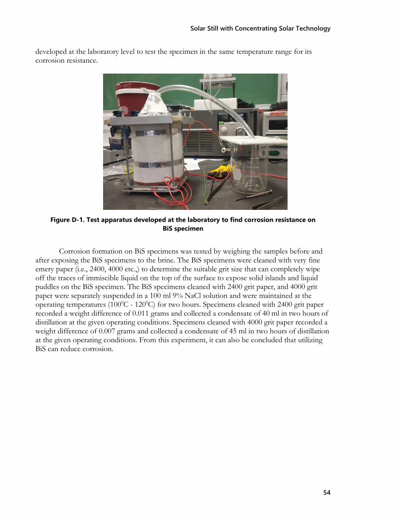
Solar Still with Concentrating Solar Technology
54
developed at the laboratory level to test the specimen in the same temperature range for its corrosion resistance.
Figure D-1. Test apparatus developed at the laboratory to find corrosion resistance on BiS specimen
Corrosion formation on BiS specimens was tested by weighing the samples before and
after exposing the BiS specimens to the brine. The BiS specimens were cleaned with very fine emery paper (i.e., 2400, 4000 etc.,) to determine the suitable grit size that can completely wipe off the traces of immiscible liquid on the top of the surface to expose solid islands and liquid puddles on the BiS specimen. The BiS specimens cleaned with 2400 grit paper, and 4000 grit paper were separately suspended in a 100 ml 9% NaCl solution and were maintained at the operating temperatures (1000C - 1200C) for two hours. Specimens cleaned with 2400 grit paper recorded a weight difference of 0.011 grams and collected a condensate of 40 ml in two hours of distillation at the given operating conditions. Specimens cleaned with 4000 grit paper recorded a weight difference of 0.007 grams and collected a condensate of 45 ml in two hours of distillation at the given operating conditions. From this experiment, it can also be concluded that utilizing BiS can reduce corrosion.

Solar Still with Concentrating Solar Technology
55
Appendix - E: Superhydrophobic Coatings on Glass Cover
A one-step method based on silica nanoparticles was used to fabricate superhydrophobic coatings (Rajaseenivasan et al., 2014). We used co-hydrolyzed tetraethyl orthosilicate (TEOS) and a fluorinated alkyl silane (FAS) under basic conditions. Figure E-1 shows the water contact angles with different injection volumes.
Figure E-1. Water contact angles for different injection volume using spray method
The highest contact angle is 157.6°, greater than 150°, which indicates that this coating is superhydrophobic. The best result was obtained under 0.4 ml of injected sol-gel solution with a psi pressure of 30. Figure E-2 shows the transmittance of the glass slides with and without coating at full range spectrum (190 nm – 1000 nm). The maximum transmittances of coated and uncoated glass slides were 71.8% and 91.4%, respectively. The significant difference of transmittance is about 20% between uncoated and coated glass slides.
Figure E-2. Measured transmittance of glass slides with and without coating

Solar Still with Concentrating Solar Technology
56
Effects of salinity on the evaporation performance of still A without coating
Table E-1 provides the water quality of the produced water used in the experiments. Pictures of the water treated before and after the solar evaporation experiments are shown in Figure E-3. The results of the experiments are summarized in Figures E-4 and E-5 and Table E- 2.
Table E-1. Water quality of produced water
TDS, mg/L Turbidity, NTU pH value TOC, mg/L 130,000~143,873 58 6.9~7.3 16
Figure E-3. (a) feed water; (b) product water
Figure E-4. TDS removal effect for various feed water TDS concentration for solar Still A

Solar Still with Concentrating Solar Technology
57
Figure E-5 shows the results of the effects of salinity (total dissolved solids, TDS) on the removal efficiency of TDS with still A without any coating. The removal efficiency of TDS is more than 97%. This indicates that our solar still design has advantages for desalination considering its excellent TDS removal performance and low energy costs.
Figure E-5. Temperature variation of the still with radiation time from the sun (Ta=temperature of ambient, Tb= temperature of water in evaporation basin, Tisg= temperature of inner glass
cover surface, Tosg= outer glass cover surface) As shown in Figure E-5, it is apparent that temperatures increased and reached their
peak values at around 12:20 to 13:20 where the solar irradiation was highest during the day. The temperature of water in the evaporation basin is higher than the inner surface of the glass cover.
As shown in Table E-2, the TDS concentration of fresh water was less than 50 mg/L
when the TDS of the feed water was below 10,000 mg/L and it is easy to estimate that the TDS of fresh water was less than 150 mg/L even though the TDS of feed water ranged between 14,850 mg/L and 143,873 mg/L. The conductivity of fresh water increased with the increase of TDS concentration of produced water.
Table E-2. Results of distillation using still A
TDS of feed water (mg/L)
Maximum hourly yield of fresh water per unit evaporation
area(ml/m2)
Fresh water productivity(ml/m2-day)
TDS of product water (mg/L)
1905 590 316 49
3050 578 312 / 6158 629 411 48
14850 510 319 80
67910 680 343 147
143873 541 316 148
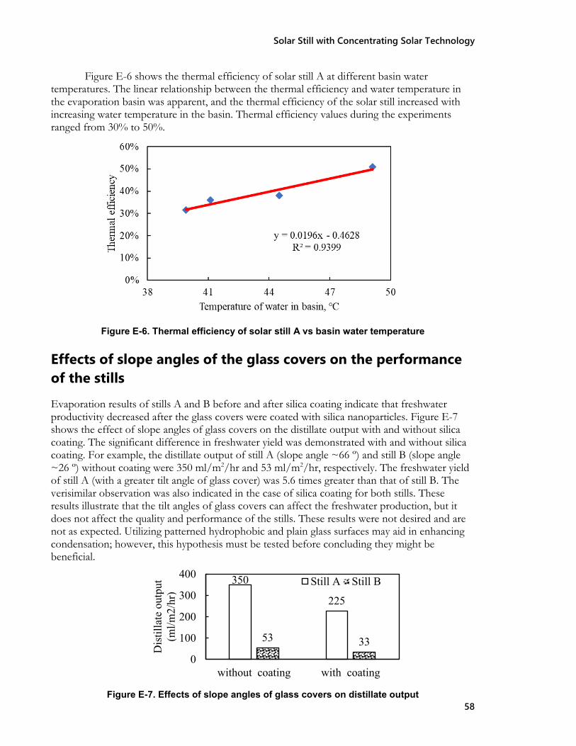
Solar Still with Concentrating Solar Technology
58
Figure E-6 shows the thermal efficiency of solar still A at different basin water temperatures. The linear relationship between the thermal efficiency and water temperature in the evaporation basin was apparent, and the thermal efficiency of the solar still increased with increasing water temperature in the basin. Thermal efficiency values during the experiments ranged from 30% to 50%.
Figure E-6. Thermal efficiency of solar still A vs basin water temperature
Effects of slope angles of the glass covers on the performance of the stills Evaporation results of stills A and B before and after silica coating indicate that freshwater productivity decreased after the glass covers were coated with silica nanoparticles. Figure E-7 shows the effect of slope angles of glass covers on the distillate output with and without silica coating. The significant difference in freshwater yield was demonstrated with and without silica coating. For example, the distillate output of still A (slope angle ~66 º) and still B (slope angle ~26 º) without coating were 350 ml/m2/hr and 53 ml/m2/hr, respectively. The freshwater yield of still A (with a greater tilt angle of glass cover) was 5.6 times greater than that of still B. The verisimilar observation was also indicated in the case of silica coating for both stills. These results illustrate that the tilt angles of glass covers can affect the freshwater production, but it does not affect the quality and performance of the stills. These results were not desired and are not as expected. Utilizing patterned hydrophobic and plain glass surfaces may aid in enhancing condensation; however, this hypothesis must be tested before concluding they might be beneficial.
400
300
200
100
0 without coating with coating
Figure E-7. Effects of slope angles of glass covers on distillate output
350 Still A Still B
225
53 33
Dis
tilla
te o
utpu
t (m
l/m2/
hr)

Solar Still with Concentrating Solar Technology
59
[( )𝑛𝑛𝑛𝑛 ]
Appendix - F: Preliminary Economic Analysis for a Centralized Mirror
Preliminary Analysis for a Centralized Mirror The economic feasibility of any solar still can be assessed primarily based on ‘the unit cost of desalination of saline water’ (UCdw) and ‘payback period’ (np) of the investment made to build the solar stills. Variables involved in the economic analysis of the solar still include:
• Present capital cost of the solar still (Cs) • Interest rate on annual basis (i) • Expected useful life of the solar still in years (n) • Salvage value of the solar still in the future (S) • Average annual productivity in liters (M yearly) • Annual operation and maintenance costs (OMC) • Number of clear days (ND) • Mean daily distil output (md) • Selling price of distilled water per liter (SP)
The unit cost of desalination of saline water (UCdw) is the ratio of the total annualized cost of the passive solar still per unit area and average annual productivity in liters of the solar still per unit area. It can be estimated using the following equations:
(F-1)
Now, with
TAC = ACS+OMC-ASV (F-2)
ACS = Annualized capital cost of solar still = CS X CRF (F-3)
where CRF = Capital Recovery Factor = (F-4)
OMC = Operation and Maintenance cost, usually considered as 15% of the annualized capital cost.
ASV = Annualized Salvage Cost = S X (SFF) (F-5)
where SFF = Shrinking Fund Factor = (F-6)
Myearly = Average annual productivity of still in 𝐿𝐿⁄𝑚𝑚2 = md X Nd, (F-7)
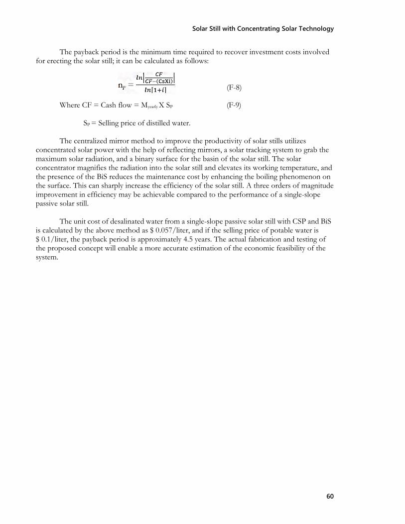
Solar Still with Concentrating Solar Technology
60
The payback period is the minimum time required to recover investment costs involved for erecting the solar still; it can be calculated as follows:
(F-8)
Where CF = Cash flow = Myearly X SP (F-9)
SP = Selling price of distilled water.
The centralized mirror method to improve the productivity of solar stills utilizes concentrated solar power with the help of reflecting mirrors, a solar tracking system to grab the maximum solar radiation, and a binary surface for the basin of the solar still. The solar concentrator magnifies the radiation into the solar still and elevates its working temperature, and the presence of the BiS reduces the maintenance cost by enhancing the boiling phenomenon on the surface. This can sharply increase the efficiency of the solar still. A three orders of magnitude improvement in efficiency may be achievable compared to the performance of a single-slope passive solar still.
The unit cost of desalinated water from a single-slope passive solar still with CSP and BiS
is calculated by the above method as $ 0.057/liter, and if the selling price of potable water is $ 0.1/liter, the payback period is approximately 4.5 years. The actual fabrication and testing of the proposed concept will enable a more accurate estimation of the economic feasibility of the system.

Solar Still with Concentrating Solar Technology
61
Appendix - G: Thermal Model Parametric Study The developed model was initially used to simulate the solar still performance without the Fresnel lens. Table G-1 shows the physical input parameters for the model. In our experiments, a fan is used to maintain forced convection on the glass. Hence, the wind velocity of 4.2 m/s was used at all times. A smooth curve for ambient temperature was used in the numerical model to eliminate the sudden changes in temperature and hence all other factors estimated.
Table G-1. Physical input parameters used in the model
Parameters Numerical values Basin area, 𝐴𝐴𝑏𝑏 0.2025 m2
Basin absorptivity, 𝛼𝛼𝑏𝑏 0.90 Glass absorptivity, 𝛼𝛼𝑔𝑔 0.05 Water reflectivity, 𝛼𝛼𝑤𝑤 0.05 Glass reflectivity, 𝑅𝑅𝑔𝑔 0.05 Water reflectivity, 𝑅𝑅𝑤𝑤 0.05 Glass emissivity, 𝜀𝜀𝑔𝑔 0.94 Water emissivity, 𝜀𝜀𝑤𝑤 0.95 Water heat capacity, 𝑐𝑐𝑤𝑤 4180 J/kg K Time, 𝑡𝑡 3600 s Thickness of glass cover, 𝐿𝐿g 0.004 m Thickness of insulation, 𝐿𝐿i 0.1016 m Glass thermal conductivity, 𝑘𝑘g
1.03 W/m K
Insulation thermal conductivity, 𝑘𝑘i
0.0363 W/m K
𝜎𝜎 5.6697x10⁻⁸ W/m2 K4
ℎ𝑤𝑤 250 W/m2 K Water density, 𝜌𝜌𝑤𝑤 1000 kg/m3
Water depth, 𝑑𝑑 0.02 m Wind velocity with fan 4.2 m/s
A comparison of the experiments and the numerical model is shown in Figures G-1 and G-2. It can be observed that both experimental and numerical results show the same trend in temperature rise and decrease with respect to time. The average difference between the numerical and experimental results was found to be 4% for water temperature, 9% for glass temperature, and 20% for productivity.

Solar Still with Concentrating Solar Technology
62
Figure G-1. Hourly variation of experimental and theoretical values of water temperatures
Figure G-2. Hourly variation of experimental and theoretical values of glass temperatures
Parametric Study: Effect of geographic location It can be observed, and it is known that the still temperatures will depend on the amount of heat input to the still along with the still parameters. Though several studies in the literature mentioned the importance of parameters of the still, none of the studies looked into the performance of a single still at different geographic locations. Apart from the solar still parameters, geographic factors that affect the solar still performance are the solar insolation, ambient temperature, and wind velocity. In this work, we used the model developed for the current solar still to estimate its performance when it is used in different tropical locations around the world.

Solar Still with Concentrating Solar Technology
63
For the parametric study, the insolation and ambient temperature data used for different locations in May (see Table G-2) were adopted from the European Commission’s Photovoltaic Geographical Information System (https://re.jrc.ec.europa.eu/pvg_tools/en/tools.html#PV). Data are shown in figures G-3 and G-4. As can be seen in the figures, Bridgetown has the lowest average insolation value, and Hamersley has the highest average insolation followed by Cairo. Figure G-5 shows the predicted basin temperature at all five locations. Figure G-6 shows the predicted water temperatures at all five locations. Figure G-7 shows the predicted water productivity. Rewa has the highest ambient temperature followed by Bridgetown. The simulations showed that the water temperature, basin temperature, and productivity are highest for Rewa and are lowest for Hamersley.
Table G-2. Geographical locations used in the study
Location Latitude (oN) Las Cruces, New Mexico, USA 32.320 Rewa, Madhya Pradesh, India 24.537 Cairo, Egypt 30.015 Bridgetown, Barbados 13.161 Hamersley Range, Western Australia, Australia -23.198
Figure G-3. Hourly variation of insolation in May for different locations
Figure G-4. Hourly variation of ambient temperature in May for different locations

Solar Still with Concentrating Solar Technology
64
Figure G-5. Hourly variation of basin temperature estimated for different locations
Figure G-6. Hourly variation of water temperature estimated for different locations
Figure G-7. Cumulative productivity estimated for different locations

Solar Still with Concentrating Solar Technology
65
Table G-2 shows the average insolation and average ambient temperatures at these locations along with the cumulative productivity at each of the locations.
Table G-2. Solar conditions and productivity in different locations Average
Insolation (W/m2)
Average Ta (oC)
Cumulative Productivity (Kg/m2)
Las Cruces, New Mexico, USA 705 24.43 1.05
Rewa, Madhya Pradesh, India 679 38.13 1.46
Cairo, Egypt 709 28.88 1.23 Bridgetown, Barbados 600 29.44 1.04 Hamersley Range, Western Australia, Australia
730 15.33 0.82
It can be observed from the table that the productivity of the same still is different at each location. The following observations are made from the table. 1. Although the average insolation is not the highest, the cumulative productivity is highest for Rewa, since it has the highest average ambient temperature. 2. The average insolation is the highest for Hamersley Range; however, the productivity is the lowest at this location. It should be noted that the average ambient temperature is the lowest at this location. 3. Both Las Cruces and Bridgetown have similar productivity, though Las Cruces has the higher insolation and the lower ambient temperature of the locations. 4. Cairo has the second highest productivity and has both an average ambient temperature and the second highest insolation.
From points 1 and 2, it is evident that higher ambient temperature aids in increasing productivity. This could be because of the reduction in heat losses from the basin and the glass. However, for condensation of the vapor on the glass, it is important to have a lower ambient temperature. In the current case, a constant forced convection value was used for the glass, assuming a fan is being used for cooling the glass. This suggests that the radiation heat loss from the glass is important as well. Though heat losses from the basin are easily reduced by using insulation, heat loss from the glass, especially radiation, is not easy to reduce since the glass is exposed to the sunlight. From this study, it is observed that an increase in the ambient temperature will help with reducing the radiation heat loss from the glass. From point 3, it can be concluded that higher output is possible even when the ambient temperature is low, whenever insolation is high. This is true since the amount of heat input increases with insolation, thus increasing the amount of water evaporated. However, the increase will be more useful if the heat losses are reduced.

Solar Still with Concentrating Solar Technology
66

Solar Still with Concentrating Solar Technology
67
Appendix - H: Literature Review on Various Solar Stills
We have performed a detailed literature review of solar stills and submitted a review article on various solar stills. Here, we summarize the different solar stills reviewed under each thermal process category: H-1 Amplified solar insolation or increased solar input per unit area • Bait and Si-Ameur, 2017 numerically analyzed a double-slope single-basin solar still was coupled with a
solar collector. The daily yield obtained was 4 kg/m2/day and the improvement in daily yield was 44.4%. Ambient parameters are: solar radiation between 400 – 1100 W/m2, and wind speed is between 0 to 6.0 m/s.
• El-Sebaii et al., 2008 numerically analyzed a single-slope single-basin solar still was coupled with a shallow solar pond at Tanta, Egypt (30°47’ N). The improvement in daily yield was 52.36%.
• Rajaseenivasan et al., 2014 experimentally studied a single-slope single-basin solar still was integrated with an internal horizontal flat plate solar collector in Tamil Nadu, India. The daily yield obtained was 5.82 kg/m2/day. Ambient parameters are: solar radiation of 100 – 1000 W/m2, temperature is between 29 – 33 0C, and wind speed is between 0.3 to 1.1 m/s
• Badran et al., 2005 experimentally studied a pyramid solar still coupled with flat plate solar collector in Amman, Jordan. The daily yield obtained was 5 kg/m2/day and the improvement in daily yield was 52%. Ambient parameters are: solar radiation of 500 – 960 W/m2 and temperature is between 17 – 26 0C.
• Ei-Bahi and Inan, 1999 experimentally studied a double slope solar still with a small inclination and an internal reflector in Ankara, Turkey (39°57’ N). The daily yield obtained was 7 kg/m2/day and the improvement in daily yield was 42.8%. Ambient parameters are: solar radiation of 210 – 930 W/m2 and temperature is between 18 – 40 0C.
• Omara et al., 2013 experimentally studied a stepped solar still with internal reflectors in Kafrelshei kh, Egypt (30°04’ N). The daily yield obtained was 6.35 kg/m2/day and the improvement in daily yield was 75%. Ambient parameters are: solar radiation of 50 – 1029 W/m2 and temperature is between 27 – 33 0C.
• Nassar et al., 2007 experimentally studied a concave mirror that was used to concentrate sunlight to its focal point, where a saline water container was placed; the container worked under a low pressure of 25 kPa for reducing the boiling point of basin water; an external condenser was used to distillate heat vapor, in Tripoli, Libyan (27°36’ N). The daily yield obtained was 20.11 kg/m2/day. Ambient parameters are: solar radiation between 360 – 933 W/m2, temperature is between 23 – 34 0C, and wind speed is between 1 to 1.5 m/s.
• Abdel-Rehim and Lasheen, 2007 experimentally studied a general single slope solar still coupled with a parabolic reflector in Cairo, Egypt. The improvement in daily yield was 18%. Ambient parameters are: solar radiation of 200 – 850 W/m2 and temperature is between 27 – 33 0C.
• Gorjian et al., 2014 experimentally studied a stand-alone desalination system with a dish-shaped parabolic reflector and an external condenser in Tehran, Iran. The daily yield obtained was 5.11 kg/m2/day. Ambient parameters are: solar radiation of 630 W/m2, temperature is 17 0C on average, and average wind speed is 1.0 m/s.

Solar Still with Concentrating Solar Technology
68
• Fathy et al., 2018 experimentally studied a double-slope single-basin solar still coupled with a parabolic
trough reflector in Sohag, Egypt. For the fixed summer model, the daily yield obtained was 8.53 kg/m2/day and the improvement in daily yield was 89.1%, for the summer tracking method 10.93 kg/m2/day and 142.2% were obtained, for the fixed winter model 4.03kg/m2/day and 74.5% obtained, and for the winter tracking model 5.11 kg/m2/day and 121.2% were obtained. Ambient parameters are: solar radiation of 1100 W/m2 and temperature between 32.5-37.5 0C for the summer, and solar radiation 830 W/m2 with temperature.
• Satyamurty and El-Agouz, 2019 experimentally studied a single-slope single-basin solar still coupled with 15 small-sized convex lenses in Tanta, Egypt. The improvement in daily yield was 26.64%. Ambient parameters are: solar radiation of 200-989 W/m2, temperature is between 24.0-25.6 0C, and wind speed is between 0-2.0 m/s.
• Abdelsalam and Abdel-Mesih, 2014 experimentally studied a single-slope single-basin solar still coupled with four identical linear Fresnel lenses in Cairo, Egypt. The daily yield obtained was 2.35 kg/m2/day and the improvement daily yield was 213.3%. Ambient parameters are: average solar radiation of 697 W/m2 and average temperature of 23.0 0C.
• Muraleedharan et al., 2019 experimentally studied a single-slope single-basin solar still coupled with a linear Fresnel lens-based concentrator in Trichy, India. The daily yield obtained was 12.19 kg/m2/day and the improvement daily yield was 250.3%. Ambient parameters are: solar radiation of 764-770 W/m2.
• Mu et al., 2019 experimentally studied a single-slope single-basin solar still coupled with a large-sized point-focusing Fresnel lens, with a nucleate boiling effect introduced in Las Cruces, USA. The daily yield obtained was 9.22 kg/m2/day and the improvement daily yield was 467.4%. Ambient parameters are: solar radiation of 0-1100 W/m2, temperature between 27.5-41.4 0C, and wind speeds of 0-0.7 m/s.
H-2 Enhanced Condensation
• Tiwari and Rao, 1984 numerically studied water flow with a uniform velocity over a glass cover in New Delhi, India. The improvement daily yield was 100%. Ambient parameters are: solar radiation of 0-800 W/m2, temperature between 25-43 0C, and wind speeds of 5.0 m/s.
• Arunkumar et al., 2012 experimentally studied a hemispherical solar still with and without covering water film in Coimbatore, India. The daily yield obtained was 4.2 kg/m2/day and the improvement daily yield was 15.0%. Ambient parameters are: solar radiation of 732 W/m2.
• Rahmani and Boutriaa, 2017 experimentally studied a general single-slope solar still coupled with an external condenser at the University of Oum el Bouaghi, Algeria. The daily yield obtained was 4.73 kg/m2/day. Ambient parameters are: solar radiation between 300-950 W/m2, temperature between 21-31.5 0C, and wind speeds of 1.0-5.8 m/s.
• Khalifa et al., 1999 experimentally studied a general single-slope solar still coupled with an internal condenser. The daily yield obtained was 5.96 kg/m2/day.
• Refalo et al., 2016 experimentally studied a general single slope-solar still coupled with an external condenser immersed in seawater in Malta, Europe. The daily yield obtained was 5.1 kg/m2/day, and the improvement daily yield was 8.5%.
• Zanganeh et al., 2019 experimentally studied a general single slope solar still with a tailored condensation surface via nano-coating process. The improvement in daily yield was 24% for nano-coated all, 23% for nano coated glass, and 44% for nano coated iron.

Solar Still with Concentrating Solar Technology
69
H-3 Heat Storage/Recuperation
• El-Sebaii et al., 2009 numerically studied stearic acid used as phase change material in Jeddah, Saudi Arabia. The daily yield obtained was 9.01 kg/m2/day and the improvement daily yield was 80%. Ambient parameters are: solar radiation between 0-910 W/m2, and temperature between 30-38 0C.
• Tabrizi et al., 2010 experimentally studied stepped solar still coupled with paraffin wax in Zahedan, Iran. The daily yield obtained was 4.85 kg/m2/day. Ambient parameters are: temperature between 25-33 0C, and wind speeds between 0-9.0 m/s.
• Sathyamurthy et al., 2014 experimentally studied a triangular pyramid solar still with phase change material in Chennai, India. The daily yield obtained was 5.5 kg/m2/day and the improvement daily yield was 57%. Ambient parameters are: solar radiation between 100-1000 W/m2, and temperature between 25-31 0C.
• Kabeel and Abdelgaied, 2016 experimentally studied a general single-slope solar still with Paraffin wax used as energy storage material at Tanta University, Egypt. The daily yield obtained was 7.54 kg/m2/day and the improvement daily yield was 67.2%. Ambient parameters are: solar radiation between 220-1080 W/m2, temperature between 23-39 0C, and wind speeds between 0.4-5.2 m/s.
• El Sebaii, 2005 numerically studied recovering latent heat with triple effect solar still in Tanta, Egypt. The daily yield obtained was 12.635 kg/m2/day. Ambient parameters are: solar radiation between 0-1057 W/m2, and temperature between 28-30 0C.
• Rajaseenivasan et al., 2013 experimentally studied a double-effect solar still with upper basin integrated with trays at the bottom in Kovilpatti, India. The daily yield obtained was 4.75 kg/m2/day in double effect mode and 2.57 kg/m2/day in single effect mode.
• Estahbanti et al., 2015 experimentally studied multi-effect double-slope solar still in Tehran, Iran. The daily yield obtained was 17.67 kg/m2/day and the improvement daily yield was 42.5%. Ambient parameters are: simulated solar radiation between 0-600 W/m2, and the test was held indoors.
H-4 Enhanced Evaporation
• Gupta et al., 2016 experimentally studied a general single-slope solar still with CuO NPs dispersed in a basin in Jabalpur, India. The daily yield obtained was 3.445 kg/m2/day and the improvement daily yield was 22.4% for 5 cm water depth. The daily yield obtained was 3.058 kg/m2/day and the improvement daily yield was 30.1% for 10 cm water depth. Ambient parameters are: solar radiation between 0-881 W/m2 for 5 cm water depth, 0-852 W/m2 for 10 cm depth and temperature between 25-36 0C for both.
• Kabeel et al., 2017 experimentally studied a general single-slope solar still with CuO NPs coated to the absorber in Kafrel-sheikh, Egypt. The daily yield obtained was 4.0 kg/m2/day and the improvement daily yield was 17.6%. Ambient parameters are: solar radiation of 600 W/m2, temperature of 29 0C, and wind speeds of 1.8 m/s.
• Saleh et al., 2017 experimentally studied a semi-cylindrical single-effect solar still with ZnO NPs dispersed in a basin in Suez. The daily yield obtained was 4.2 kg/m2/day and the improvement daily yield was 30%. Ambient parameters are: solar radiation between 50-800 W/m2, and temperature between 20-40 0C.
• Chen et al., 2019 experimentally studied a solar evaporation generation system with MWCNTs dispersed into saline water in Xi Chang, China.
• Hansen et al., 2015 experimentally studied stepped solar still with various wick materials and wire mesh in Kovilpatti, India. The daily yield obtained was 3.23 kg/m2/day and the improvement daily yield was 29.2% for wood pulp paper, the daily yield was 3.95 kg/m2/day and the improvement daily yield was

Solar Still with Concentrating Solar Technology
70
• 58% for polystyrene sponge, and the daily yield was 4.28 kg/m2/day and the improvement daily yield
was 71.2% for water coral fleece. Ambient parameters are: solar radiation between 0-920 W/m2, with wind speeds between 0.2-3.3 m/s.
• Haddad et al., 2017 experimentally studied a general single-slope solar still coupled with a DC motor- driven vertical wick strip in M’sila City, Algeria. The daily yield obtained was 5.03 kg/m2/day and the improvement daily yield was 14.72% in the summer. The daily yield obtained was 7.17 kg/m2/day and the improvement daily yield was 51.1% in the winter. Summer ambient parameters are: solar radiation between 0-950 W/m2, temperature between 5-21 0C, and wind speeds between 0-5.8 m/s. Winter ambient parameters are: solar radiation between 0-750 W/m2, temperature between 17-35 0C, and wind speeds between 2.1-8.0 m/s.
• Rashidi et al., 2018 experimentally studied a general single-slope solar still coupled with a reticular porous layer in Semman, Iran. The daily yield obtained was 3.829 kg/m2/day and the improvement daily yield was 17.35%. Ambient parameters are: solar radiation of 775 W/m2, and temperature of 35 0C.
• Alaian et al., 2016 experimentally studied a general single-slope solar still coupled with pin-finned wick at Mansoura University. The improvement daily yield was 23%. Ambient parameters are: temperature between 20-26 0C.
• El Sebaii et al., 2015 numerically and experimentally studied enlarging evaporation and exposure areas with fins integrated at the basin bottom in Tanta Egypt. The daily yield obtained was 5.377 kg/m2/day and the improvement daily yield was 13.7%. Ambient parameters are: solar radiation between 0-910 W/m2, and temperature between 25-35 0C.
• Ni et al., 2019 experimentally studied solar-driven interfacial evaporation concept where the evaporation structure was comprised of two layers, the top layer was made by hydrophilic black cellulose fabric, and the lower layer was made by cellulose fabric and expanded polystyrene foam in an alternating pattern in Pleasure Bay, Boston, USA. The daily yield obtained was 2.5 kg/m2/day. Ambient parameters are: solar radiation between 0-840 W/m2.
• Wang et al., 2017 experimentally studied an interfacial evaporation system fabricated via a uniform dispersion of Au NPs on pretreated filter paper in Harbin, China. The improvement daily yield was 80%. Ambient parameters are: constant solar radiation of 1000 W/m2, and constant temperature of 18 0C.
H-5 Using a hybrid improvement method
• Xiong et al., 2013 experimentally studied a triple effect solar still coupled with a vacuum tube collector in Beijing, China. The daily yield obtained was 9.61 kg/m2/day. Ambient parameters are: solar radiation between 0-1000 W/m2.
• Arunkumar et al., 2013 experimentally studied a hemispherical basin solar still coupled with a parabolic mirror for sunlight concentration and phase change material in Coimbatore, India. The daily yield obtained was 4.46 kg/m2/day with phase change material, and 3.52 kg/m2/day without. Ambient parameters are: solar radiation between 513-1067 W/m2, and temperature between 32-37 0C.
• Srithar et al., 2016 experimentally studied a triple-effect solar still coupled with cover cooling and parabolic dish concentrator in Tamil Nadu, India. The daily yield obtained was 16.94 kg/m2/day. Ambient parameters are: solar radiation between 0-960 W/m2, and temperature between 32-36 0C.
• Feilizadeh et al., 2015 experimentally studied a 4-effect double slope solar still coupled with 3 flat plate solar collectors and water cooling effect in Shiraz, India. The daily yield obtained was 31.60 kg/m2/day in the summer and 27.83 kg/m2/day in the winter. Summer ambient parameters are: wind speed of 2 m/s. Winter ambient parameters are: solar radiation between 0-940 W/m2, temperature between 8-27 0C

Solar Still with Concentrating Solar Technology
71
• and wind speed of 1 m/s. • El-Samadony et al., 2015 experimentally studied a stepped solar still with internal and external reflectors
and external condenser model in Kafrelsheikh, Egypt. The daily yield obtained was 9 kg/m2/day and the improvement daily yield was 165%. Ambient parameters are: solar radiation between 25-1200 W/m2, temperature between 25-34 0C, and wind speed between 0.12-34 m/s.
• Shalaby et al., 2016 experimentally studied a v-corrugated absorber used in conjunction with PCM in Tanta, India. The daily yield obtained was 25 kg/day. Ambient parameters are: solar radiation between 0-913 W/m2, and temperature between 30-36 0C.
• Sahota et al., 2017 numerically studied a double-slope solar still enhanced by various nanoparticles and a number of flat plate collectors in New Delhi, India. The daily yield obtained was 4.87 kg with improvement daily yield 7.26% for TiO2NPs. The daily yield obtained was 5.74 kg with improvement daily yield 26.4% for Al2O3NPs. The daily yield obtained was 5.97 kg with improvement daily yield 31.49% for CuONPs. Ambient parameters are: solar radiation between 0-870 W/m2, and temperature between 23-35 0C.
• Sharshir et al., 2017 experimentally studied graphite and copper oxide NPs with water cooling effect for the glass cover in a single-slope solar still in Wuhan, China. The improvement daily yield was 57.6% for Graphite NPs and 47.8% for Copper NPs. Ambient parameters are: solar radiation between 45-895 W/m2, temperature between 26-36 0C and wind speed between 0.1-6.5 m/s.
• Sharshir et al., 2017 experimentally studied flake graphite NPs using PCM and cooling water in a single-slope solar cell in Wuhan, China. The improvement daily yield was 73.8%. Ambient parameters are: solar radiation between 0-850 W/m2, and temperature between 13-20 0C.
• Rufuss et al., 2017 experimentally studied copper oxide NPs and PCM mixed in a single-slope solar still, in Chennai, India. The daily yield obtained was 5.28 kg/m2/day and the improvement daily yield was 35%. Ambient parameters are: solar radiation between 0-830 W/m2, and wind speeds between 0.9-2.2 m/s.

Solar Still with Concentrating Solar Technology
72
References for Appendix H Abdelsalam, T.I. and B. Abdel-Mesih. 2014, An Experimental Study on the Effect of Using Fresnel Lenses on the Performance of Solar Stills in International Congress on Energy Efficiency and Energy Related Materials (ENEFM2013), Springer.
Abdel-Rehim, Z.S. and A. Lasheen, 2007, Experimental and theoretical study of a solar desalination system located in Cairo, Egypt. Desalination, 217(1-3): p. 52-64.
Alaian, W.M., Elnegiry, E.A., and Hamed, A.M., 2016, Experimental investigation on the performance of solar still augmented with pin-finned wick. Desalination, 379: p. 10-15.
Arunkumar, T., et al., 2012, An experimental study on a hemispherical solar still. Desalination, 286: p. 342-348.
Arunkumar, T., et al., 2013, The augmentation of distillate yield by using concentrator coupled solar still with phase change material. Desalination, 314: p. 189-192.
Badran, A.A., et al., 2005, A solar still augmented with a flat-plate collector. Desalination, 172(3): p. 227-234.
Bait, O. and M. Si-Ameur, 2017, Tubular solar-energy collector integration: Performance enhancement of classical distillation unit, Energy, 141: p. 818-838.
Chen, W.J., et al., 2019, Application of recoverable carbon nanotube nanofluids in solar desalination system: An experimental investigation. Desalination, 451: p. 92-101.
El-Bahi, A. and D. Inan, 1999, A solar still with minimum inclination, coupled to an outside condenser. Desalination, 123(1): p. 79-83.
El-Samadony, Y.A.F., Abdullah, A.S., and Omara, Z.M., 2015, Experimental Study of Stepped Solar Still Integrated with Reflectors and External Condenser. Experimental Heat Transfer, 28(4): p. 392-404.
El-Sebaii, A.A., et al., 2008, Thermal performance of a single-basin solar still integrated with a shallow solar pond. Energy Conversion and Management 49(10): p. 2839-2848.
El-Sebaii, A.A., 2005, Thermal performance of a triple-basin solar still. Desalination, 174(1): p. 23-37.
El-Sebaii, A.A., et al., 2009, Thermal performance of a single basin solar still with PCM as a storage medium. Applied Energy, 86(7-8): p. 1187-1195.

Solar Still with Concentrating Solar Technology
73
El-Sebaii, A.A., et al., 2015, Effect of fin configuration parameters on single basin solar still performance. Desalination, 365: p. 15-24.
Estahbanati, M.K., et al., 2015, Experimental investigation of a multi-effect active solar still: the effect of the number of stages, 137: p. 46-55.
Fathy, M., H. Hassan, and M.S. Ahmed, 2018, Experimental study on the effect of coupling parabolic trough collector with double slope solar still on its performance. Solar Energy, 163: p. 54-61.
Feilizadeh, M., et al., 2015, Year-round outdoor experiments on a multi-stage active solar still with different numbers of solar collectors. Applied Energy, 152: p. 39-46.
Gorjian, S., et al., 2014, Experimental performance evaluation of a stand-alone point-focus parabolic solar still. Desalination, 352: p. 1-17.
Gupta, B., et al., 2016, Performance enhancement using nano particles in modified passive solar still. Procedia Technology, 25: p. 1209-1216.
Haddad, Z., Chaker, A., and Rahmani, A., 2017, Improving the basin type solar still performances using a vertical rotating wick. Desalination, 418: p. 71-78.
Hansen, R.S., Narayanan, C.S., and Murugavel, K.K., 2015, Performance analysis on inclined solar still with different new wick materials and wire mesh. Desalination, 358: p. 1-8.
Kabeel, A.E. and Abdelgaied, M., 2016, Improving the performance of solar still by using PCM as a thermal storage medium under Egyptian conditions. Desalination, 383: p. 22-28.
Kabeel, A., et al., 2017, Augmentation of a solar still distillate yield via absorber plate coated with black nanoparticles. Alexandria Engineering Journal, 56(4): p. 433-438.
Khalifa, A.J.N., Al-Jubouri, A., and Abed, M.K., 1999, An experimental study on modified simple solar stills. Energy Conversion and Management, 40(17): p. 1835-1847.
Mu, L., et al., 2019, Enhancing the performance of a single-basin single-slope solar still by using Fresnel lens: Experimental study. Journal of Cleaner Production, 239: p. 118094.
Muraleedharan, M., et al., 2019, Modified active solar distillation system employing directly absorbing Therminol 55–Al2O3 nano heat transfer fluid and Fresnel lens concentrator. Desalination, 457: p. 32-38.
Nassar, Y.F., S.A. Yousif, and A.A. Salem, 2007, The second generation of the solar desalination systems. Desalination, 209(1-3): p. 177-181.

Solar Still with Concentrating Solar Technology
74
Ni, G., et al., 2018, A salt-rejecting floating solar still for low-cost desalination. Energy & Environmental Science, 11(6): p. 1510-1519.
Omara, Z.M., A.E. Kabeel, and M.M. Younes, 2013, Enhancing the stepped solar still performance using internal reflectors. Desalination, 314: p. 67-72.
Rahmani, A. and Boutriaa, A., 2017, Numerical and experimental study of a passive solar still integrated with an external condenser. International Journal of Hydrogen Energy, 42(8): p. 29047-29055.
Rajaseenivasan, T. and Murugavel, Kalidasa K., 2013, Theoretical and experimental investigation on double basin double slope solar still. Desalination, 319: p. 25-32.
Rajaseenivasan, T., P.N. Raja, and K. Srithar, 2014, An experimental investigation on a solar still with an integrated flat plate collector. Desalination, 347: p. 131-137.
Rashidi, S., et al., 2018, Enhancement of solar still by reticular porous media: Experimental investigation with exergy and economic analysis. Applied Thermal Engineering, 130: p. 1341- 1348.
Refalo, P., Ghirlando, R., and Abela, S., 2016, The use of a solar chimney and condensers to enhance the productivity of a solar still. Desalination and Water Treatment, 57(48-49): p. 23024-23037.
Rufuss, D.D.W., et al., 2017, Nanoparticles Enhanced Phase Change Material (NPCM) as Heat Storage in Solar Still Application for Productivity Enhancement. Energy Procedia, 141: p. 45-49.
Sahota, L., Shyam, and Tiwari, G.N., 2017, Analytical characteristic equation of nanofluid loaded active double slope solar still coupled with helically coiled heat exchanger. Energy Conversion and Management, 135: p. 308-326.
Saleh, S.M., et al., 2017, Influence of solvent in the synthesis of nano-structured ZnO by hydrothermal method and their application in solar-still. Journal of Environmental Chemical Engineering, 5(1): p. 1219-1226.
Sathyamurthy, R., et al., 2014, Effect of water mass on triangular pyramid solar still using phase change material as storage medium. Energy Procedia, 61: p. 2224-2228.
Sathyamurthy, R. and El‐Agouz, E., 2019, Experimental analysis and exergy efficiency of a conventional solar still with Fresnel lens and energy storage material. Heat Transfer—Asian Research, 48(3): p. 885-895.
Shalaby, S.M., El-Bialy, E., and El-Sebaii, A.A., 2016, An experimental investigation of a v- corrugated absorber single-basin solar still using PCM. Desalination, 398: p. 247-255.

Solar Still with Concentrating Solar Technology
75
Sharshir, S.W., et al., 2017, Enhancing the solar still performance using nanofluids and glass cover cooling: Experimental study. Applied Thermal Engineering, 113: p. 684-693.
Sharshir, S.W., et al., 2017, The effects of flake graphite nanoparticles, phase change material, and film cooling on the solar still performance. Applied Energy, 191: p. 358-366.
Srithar, K., et al., 2016, Stand alone triple basin solar desalination system with cover cooling and parabolic dish concentrator. Renewable Energy, 90: p. 157-165.
Tabrizi, F.F., Dashtban, M., and Moghaddam, H., 2010, Experimental investigation of a weir-type cascade solar still with built-in latent heat thermal energy storage system. Desalination, 260(1-3): p. 248-253.
Tiwari, G.N. and V.S.V.B. Rao, 1984, Transient Performance of a Single Basin Solar-Still with Water Flowing over the Glass Cover. Desalination, 49(3): p. 231-241.
Wang, X.Z., et al., 2017, Solar steam generation through bio-inspired interface heating of broadband-absorbing plasmonic membranes. Applied Energy, 195: p. 414-425.
Xiong, J.Y., Xie, G., and Zheng, H.F., 2013, Experimental and numerical study on a new multi-effect solar still with enhanced condensation surface. Energy Conversion and Management, 73: p. 176-185.
Zanganeh, P., et al., 2019, Productivity enhancement of solar stills by nano-coating of condensing surface. Desalination, 454: p. 1-9.