Loudspeaker Production Testing Using the Techron TEF System 20 TDS
14
Loudspeaker Production Testing Using the Techron TEF System 20 TDS Analyzer and Host PC Donald Schwing Techron, Div. Crown International Inc. Elkhart, Indiana 46517, USA and D. (Don)B. Keele,Jr. DBK Associates and Consultant to Techron, Div. Crown International Inc. Elkhart, Indiana 46517, USA Acomprehensive system for doing production testing of loudspeakers and systems is described. Multiple TEF ana- lyzers can be controlled by a single host computer to create elaborate test environments. The software allows the test engineer to orchestrate very complex test sequences while simultaneously minimizing the perceived complexity of the system as viewed by the test operator. Tests that can be incorporated in the test sequence, with pass/fail window param- eters, include any or all of the following (in any order): frequency response, phase response (polarity), harmonic track- ing, harmonic distortion (of specific harmonics), THD, THD and noise, spec_um analysis (FFT), and impedance. Op- dons include the capability to completely store all the raw data from a test run for after-the-fact review and analysis. O. INTRODUCTION 1.1. Time Delay Spectrometry Non-automated production testing of Analyzer loudspeakers and/or systems traditionally The production test system is based on the consists of at minimum, a manual by-the-ear use of the DSP-based TEF System 20 acoustic sine-sweep rub-buzz test followed by a possible analyzer which uses the patented technique of frequency response test consisting of a visual Time Delay Spectrometry pioneered by the late comparison of the measured curve with an Richard C. Heyser [1]. Analyzers based on the envelope drawn on the face of an analyzer TDS test technique can make accurate screen. The accuracy andrepeatabilityofthese measurements in the presence of high manual tests depends heavily on the skill and background noise, which makes it an ideal test condition of the operator. On the other hand, technique for use in noisy production test fully computer-based automated testing removes environments. The TDS technique uses a swept the human judgement factor from the test and sinewave test signal with an analyzer that has greatly improves the testing repeatability, matched tracking bandpass filters that can be A hardware/software system is described offset in time. The process uses a low crest- that allows fully automatic production testing of factor linearly swept sinewave as a test signal loudspeakers. The system is based on the use of which is applied to the test system during the an IBM compatible personal computer controlling whole measurement/test interval [2]. The test a DSP based test analyzer that uses the technique signal characteristics maximize the amount of test of Time Delay Spectrometry (TDS) [1, 2, 3]. The energy injected into the system under test fora system allows complex test setups to be given peaksignallevel [3]. configured, with a minimum of hardware, that The TEF System 20, shown in Fig. 1, allow many different types of production tests to utilizes aMotorola 56001 DSP chip for all be performed, internal calculations. It communicates with the analogworld through a pair of 16-bit, 64-times 1. HARDWARE over-sampled, analog to digital converters The system's hardware consists of a (synchronously sampled two-channel); and a 16- general-purpose IBM-compatible desktop bit, 8-times over-sampled, digital to analog computer controlling one or more DSP-based converter. All internal calculations are done in measurement analyzers. Up to 6 separate 24-bit fixed-point or 4-byte floating pointmath. analyzers can be controlled by one computer and All external data communication is in 4-byte incorporated into a production test setup to floating point format. increase the measurement capability. AES 1l th INTERNATIONAL CONFERENCE 277
Transcript of Loudspeaker Production Testing Using the Techron TEF System 20 TDS

Loudspeaker Production Testing Using the TechronTEF System 20 TDS Analyzer and Host PC
Donald Schwing
Techron, Div. Crown International Inc.
Elkhart, Indiana 46517, USA
and
D. (Don)B. Keele,Jr.
DBK Associates and Consultant to Techron, Div. Crown International Inc.
Elkhart, Indiana 46517, USA
A comprehensive system for doing production testing of loudspeakers and systems is described. Multiple TEF ana-lyzers can be controlled by a single host computer to create elaborate test environments. The software allows the testengineer to orchestrate very complex test sequences while simultaneously minimizing the perceived complexity of thesystem as viewed by the test operator. Tests that can be incorporated in the test sequence, with pass/fail window param-eters, include any or all of the following (in any order): frequency response, phase response (polarity), harmonic track-ing, harmonic distortion (of specific harmonics), THD, THD and noise, spec_um analysis (FFT), and impedance. Op-dons include the capability to completely store all the raw data from a test run for after-the-fact review and analysis.
O. INTRODUCTION 1.1. Time Delay SpectrometryNon-automated production testing of Analyzer
loudspeakers and/or systems traditionally The production test system is based on theconsists of at minimum, a manual by-the-ear use of the DSP-based TEF System 20 acousticsine-sweep rub-buzz test followed by a possible analyzer which uses the patented technique offrequency response test consisting of a visual Time Delay Spectrometry pioneered by the latecomparison of the measured curve with an Richard C. Heyser [1]. Analyzers based on theenvelope drawn on the face of an analyzer TDS test technique can make accuratescreen. The accuracy andrepeatabilityofthese measurements in the presence of highmanual tests depends heavily on the skill and background noise, which makes it an ideal testcondition of the operator. On the other hand, technique for use in noisy production testfully computer-based automated testing removes environments. The TDS technique uses a sweptthe human judgement factor from the test and sinewave test signal with an analyzer that hasgreatly improves the testing repeatability, matched tracking bandpass filters that can be
A hardware/software system is described offset in time. The process uses a low crest-that allows fully automatic production testing of factor linearly swept sinewave as a test signalloudspeakers. The system is based on the use of which is applied to the test system during thean IBM compatible personal computer controlling whole measurement/test interval [2]. The testa DSP based test analyzer that uses the technique signal characteristics maximize the amount of testof Time Delay Spectrometry (TDS) [1, 2, 3]. The energy injected into the system under test for asystem allows complex test setups to be given peaksignallevel [3].configured, with a minimum of hardware, that The TEF System 20, shown in Fig. 1,allow many different types of production tests to utilizes a Motorola 56001 DSP chip for allbe performed, internal calculations. It communicates with the
analog world through a pair of 16-bit, 64-times1. HARDWARE over-sampled, analog to digital converters
The system's hardware consists of a (synchronously sampled two-channel); and a 16-general-purpose IBM-compatible desktop bit, 8-times over-sampled, digital to analogcomputer controlling one or more DSP-based converter. All internal calculations are done inmeasurement analyzers. Up to 6 separate 24-bit fixed-point or 4-byte floating pointmath.analyzers can be controlled by one computer and All external data communication is in 4-byteincorporated into a production test setup to floating point format.increase the measurement capability.
AES1l th INTERNATIONALCONFERENCE 277

SCHWlNG, ET AL.
Two line level and two phantom-powered Each individual measurement can havemicrophone inputs are provided. A level control limits applied to determine pass/fail criteria foris provided for the single line-level output. TDS the composite test. These pass/fail limits can beswept measurements in the range of 10 Hz to 21 determined in several different ways including:kHz can be performed with a magnitude accuracy 1. Direct manual entry of limit envelopes,of _+0.2 dB, a phase accuracy of :!:1°, with a 2. Measurement of a standard loudspeaker anddynamic range of 96 dB. Measurement can be setting envelopes a specific range abovemade with sweep times from 0.1 to 1000 and belowthe standard,seconds (16.7 Minutes). Fig. 2 shows the 3. Establishment of limits by statisticalhardware specifications of the TEF System 20 analysis of the measurements of a batch oftaken from the specification sheet, loudspeakers utilizing standard deviation or
minimum and maximum values, and1.2. Host Control Computer 4. Setting target limits and rerunning disk-
stored batch measurement data to determineThe Speaker Test software package runs on
an IBM PC or compatible computer which is the overall pass/fail ratios.used to control the TEF System 20. For This latter method allows you to rerun aacceptable performance levels, at least a 20 MHz specific batch of speakers off-line using diskclock 386 class computer with 1 megabyte stored measurement data of the original batch. Inmemory and math coprocessor is required. A effect you are retesting the same batch ofVGA or higher monitor must be used along with loudspeakers, but without actually running themat least a 40 megabyte hard drive for storage of physically through the test setup again. Thetest data. For serial communications, an RS-232 pass/fail limits can then be manipulated to checkserial port is required which is capable of running their effect on the overall pass/fail statistics. Thisat 57.6 kilobaud. Higher speed communication allows the test engineer to rapidly see the effectcapability is available by using the TEF System on the pass/fail statistics of tightening or20 HI analyzer which includes a built-in high- loosening a specific test envelope. For example,speed 8-bit parallel I/O port which is used with a a tight window of +_2dB around a standard mightsupplied parallel-port card that plugs into the host result in a 25% reject rate. Widening the envelopePC. byjust0.5dBto+_2.5dBmightreducethereject
rate to only 5%. In this case, it might be prudentto go with the slightly wider envelope to reduce
2. SOFTWARE the reject rate.The production Speaker Test software has
the capability of testing many different types of 2.1. Organization and Menuperformance parameters including: frequency Structureresponse, polarity (phase response), harmonicdistortion (of specific harmonics), THD, THD The Speaker Test software is organizedand noise, harmonic tracking, spectrum analysis around two main modes of operation: Operator(FFT), and impedance. The extensive distortion Mode, and Engineer Mode. These two majortesting capability of the software can be used to operational modes are a direct result of how thetest for driver rubs and buzzes after a specific system is routinely used. The Operator Mode isdriver's rub/buzz distortion signature is utilized by a relatively unskilled operatoridentified. This signature can only be determined performing routine production automated testing.after exploratory distortion measurements of a The Engineer Mode is used by highly skilledbatch of drivers exhibiting the specific rub/buzz quality assurance personnel that supervise, setup,problems, anddefinethe individualmeasurementsandtests
A specific production test can contain from that make up the overall production test.one up to 20 of the several the different types ofmeasurements in any order Or combination. Forexample, a specific test can consist of twofrequency response measurements (over differentresponse ranges, say high and low), a polarity(phase) measurement, a spectrum analysis ofoutput noise measurement, a THD measurement,and an impedance vs frequency measurement.
278 AES 11th INTERNATIONAL CONFERENCE
LOUDSPEAKER PRODUCTIONTESTING USING THE TEF20 TDS ANALYZER AND HOST PC
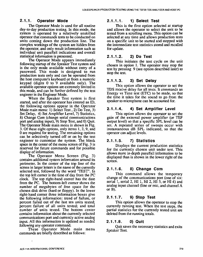
2.1.1. Operator Mode 2.1.1.1. 1) Select TestThe Operator Mode is used for all routine This is the first option selected at startup
day-to-day production testing. In this mode, the and allows the operator to select the unit to besystem is operated by a relatively unskilled tested from a scrolling menu. This option can beoperator that commands tests to be conducted on selected at any time and allows production testsunits coming down the production line. The on a specific unit to be started and stopped withcomplex workings of the system are hidden from the intermediate test statistics stored and recalledthe operator, and only result information such as for update.individual unit pass/fail indications and overallstatistical information is presented. 2.1.1.2. 2) DO Test
The Operator Mode appears immediately This initiates the test cycle on the unitfollowing startup of the Speaker Test system and chosen in option 1. The operator may stop theis the only mode available without entry of a test by pressing 9 (see option described later) topassword. This mode is designed to run stop the test.production tests only and can be operated from
the host computer's keyboard or from a numeric 2.1.1.3. 3) Set Delaykeypad (digits 0 to 9 available only). Theavailable operator options are extremely limited in This option allows the operator to set thethis mode, and can be further defined by the test TDS receive delay for all tests. It commands anengineer in the Engineer Mode. Energy vs Time test (ETC) to be made, so that
When the Speaker Test system is first the time it takes for the sound to go from thestarted, and after the operator has entered an ID, speaker to microphone can be accounted for.the following options appear in the OperatorMode main menu: 1) Select Test, 2) Do Test, 3) 2.1.1.4. 4) Set Amplifier LevelSet Delay, 4) Set Amplifier Level, 7) Statistics, This option allows the operator to set the8) Change Corn (change serial communications gain of the external power amplifier (or TEFport and analog input), 9) Stop Test, and 0) Quit. output level) so that a specific SPL level can beThe Operator Mode main menu is shown in Fig. set. A repeated series of sweeps occur with3. Of these eight options, only items 1, 2, 9, and instantaneous dB SPL indicated, so that the0 are required for testing. The remaining options operator can adjust levels.can be selectively turned off or on by the testengineer to customize the system. The blank 2.1.1.5. 7) Statisticsspace in the center of the menu screen of Fig. 3 is Displays the current production statisticsreserved for future commands and for possible for the currently chosen unit under test. Thisdisplay of information, allows more in-depth pass/fail information to be
The Operator Menu Screen (Fig. 3) displayed than is shown in the lower right of thecontains additional system information around its screen.perimeter. In the center of the top line of the
screen in larger letters is the name of the currently 2.1.1.6. 8) Change Comselected test, followed by the word "TEST". Inthe top left corner is the time of day from the PC This command allows the temporaryclock. The top right-hand corner has the date change of the communications port (one of six:from the PC. The bottom-left comer shows the serial 1, serial 2, HI 1, HI 2, HI 3, or HI 4) andnumber of megabytes of free space for the analog input channel (line or mic, and channel Achosen disk drive (hard or floppy). In the lower or B).right-hand corner three information boxes givethe following information: trend of failure, or 2.1.1.7. 9) Stop Testpercent failed out of the last ten units tested; This option allows the operator to stop thepercent failure of all units tested; and total currently running test. When the test stops, thenumber of units tested. The bottom center partial statistics for the currently tested unit arecontains information about the currently selected deleted from the running totals.communications port and currently active analoginput. All this information is updated as needed 2.1.1.8. 0) Quitfollowing any operator command. Quit saves the necessary statistics and exits
These Operator Mode main menu Speaker Test.commands are briefly described as follows:
AES 11th INTERNATIONAL CONFERENCE 279

SCHWING, ET AL.
2.1.2. Engineer Mode 2.1.2.1. File MenuThe Engineer Mode is used by skilled test The File Menu includes several commands:
personnel to define the separate measurements for manipulating files (either TDS, ETC, STN,and pass/fail criteria that make up a specific test TST, or STAT files): opening files (Open Old),sequence. Several pull-down menus are available changing drives and directories (Drive andto help the test engineer accomplish these tasks. Directory), saving files (Save As), erasing filesThe primary purpose of the Engineer Mode is the (Erase), and loading and saving of configurationcreation of a series of measurements with (setup) files (Configuration); for changingprinterassociated individual pass/fail criteria that will information (Printer Settings): resolution, pagedetermine the acceptability (overall pass/fail) of a size, and type; for printing graphs on the screenunitundertest. (PrintScreen);for displayof versionnumbers
Creation of test parameters and procedures (About TEF), for exiting the Speaker Test systemare accomplished through the use of Standards (Quit), and changing the password for entry intoFiles (STN Files) for each individual test the Engineer Mode (Password). The entries inemploying the "window of acceptability" the File Menu are:concept. An individual test includes a single typeof measurement, ie frequency response test or Open Olddistortion test etc, along with associated pass/fail Drive & Directorycriteria. The tested unit must fall within a Save Asdesignated range in order to pass; otherwise it Erasewillfail. Configuration
The Standards (STN) Files fall into eight Printer Settingscategories: Magnitude vs Frequency Response, Print ScreenHarmonic Tracking, Impedance, Phase, FFT, About TEFHarmonic Distortion, THD, and THD + Noise. QuitEach STN file contains information about its Passwordspecific measurement and pass/fail criteriaincluding: identification and descriptive 2.1.2.2. Measure Menuinformation, a window of acceptability for one of The Measure Menu contains commands tothe eight categories, measurement parameters, do several different types of measurements and todisplay parameters, input/output parameters, establish this measurement along with enteredresponse smoothing parameters (available only limits and envelope information to create afor magnitude vs frequency and harmonic Standards File (STN). The parameters for thesetracking curves), and fail margin information measurements are set either by commands in the(this allows the measured data to fall out of the Parameters Menu or set by loading a specific typeenvelope by a certain amount for up to a specific of file by using the Open Old command in thenumber of data points). A tested unit must pass File menu. A stored test sequence (calls to aeach individual test in a defined sequence of tests series of STN files stored in a TST File) can be(calls to several STN files stored in a TST File) initiated by the Do Test Sequence command. Thefor a unit to receive an overall pass. entries in the Measure Menu are:
A password is required for entry into the
Engine.er Mode from the Operator Mode. This Do Time Measurement (ETC)mlmm_zes any unauthorized modifications of the Do Frequency Measurement (TDS)loudspeaker test sequences or data. Figures 4 Do Mag. vs Frequency Measurement andthrough 8 show various images of menus and MakeStandardentry screens that can be manipulated in the Do Harmonic Tracking Measurement andEngineer Mode. The five pull-down menus Make Standardavailable in the Engineer Mode are: File, DOImpedance Measurement and MakeMeasure, Parameters, Display, and Input. These Standard
menus and their options are briefly described as DO Phase Measurement and Makefollows: Standard
Do FFr Spectrum Measurement andMake Standard
DO Harmonic Distortion Measurementand Make Standard
280 AES11thINTERNATIONALCONFERENCE
LOUDSPEAKER PRODUCTION TESTING USING THE TEF20 TDS ANALYZER AND HOST PC
Do THD Measurementand Make Toggle CursorOn or OffStandard AdjustDisplayColors
Do THD & Noise Measurement and Set Choices That Appear on OperatorMakeStandard Menu
Do Test Sequence2.1.2.5. Input Menu
2.1.2.3. Parameters Menu The Input Menu contains commands toThe Parameters Menu contains commands change the input configuration, enter microphone
to set the measurement parameters of all the and system calibration values, and to change thedifferent types of tests that Speaker Test communications port. The entries in the Inputaccomplishes. These parameters include such Menu are:items such as start and stop frequencies, sweeptime, receive delay, resolution, harmonic Settingsnumber, smoothing instructions, and input Calibrationparameters, etc., as appropriate to the specific Communicationchosen measurement. The last entry in this menuallows new production test sequences to be 2.2. Setting Production Pass/Faildefined. Figure 6 shows the entry screen that Limits
results from this command. Up to 20 individual Speaker Test has several different ways totests can be incorporated into a test sequence, set the limits and envelopes for pass/failThe entries in the Parameters Menu are: determinations. These limit determination
methods include: manual entry of limits, limitsSet Time Response Measurement determined by measurement of a single standard
Parameters (ETC) loudspeaker, limits determined by the batchSet Frequency Response Measurement statistics of measurements on several
Parameters (TDS) loudspeakers, and limits determined by repeatedSet Magnitude vs Frequency Test rerunning of previously measured batch data in a
Standard Parameters mock production run.Set HarmonicTrackingTestStandard Each Standards File (STN) contains
Parameters definitions and parameters to accomplish aSet Impedance Test Standard Parameters specific measurement, along with test limits toSet Phase Test Standard Parameters determine if the results of a specific measurementSet FFT Spectrum Test Standard pass or fail. To create a Standards File (STN),
Parameters the engineer first should set measurement andSet Harmonic Distortion Test Standard display parameters, (by using the Parameters,
Parameters Display, and Input Menus) and then proceed toSet THDTestStandardParameters the Measure Menu and select the desiredSet THD & Noise Test Standard measurement to be made a standard. The test
Parameters engineer must then choose whether he wants toDefine New Production Test Sequence make a single measurement of a standard
loudspeaker (one sample unit), or make2.1.2.4. Display Menu measurements on a number of loudspeakers
The Display Menu contains commands to (batch sampling of any number of units).set the display parameters for the test that After these measurements are made, theSpeaker Test accomplishes. Commands are also pass/fail limits and envelopes can be set usingincluded to toggle operation modes on and off, several different methods outlined as follows:and to change colors that appear on the displayscreens. The last entry allows changes to bemade to the menu items which appear on theOperator menu. The entries in the Display Menuare:
Set Time Response Display Parameters(ETC)
Set Frequency Response DisplayParameters (TDS)
Toggle Overlay Mode On or OffToggle Difference Mode On or Off
AES 11th INTERNATIONAL CONFERENCE 281

SCHWING, ET AL.
In effect you are repeatedly rerunning the2.2.1. Manual Entry of Limits original batch of loudspeakers, without actually
The upper and lower limits can be set physically doing doing it, and then changing thesimply by just entering specific limits as desired limit envelopes to yield an acceptable reject rate.without regards to a specific measurement. For Sometimes relatively small changes in envelopeexample, a rectangular window with lower limit limits can alter the overall pass/fail statisticsof 84 dB SPL and upper limit of 90 dB SPL dramatically.between 200 Hz and 10 kHz could be def'med fora small wide-range speaker system. This 3. PRODUCTION MEASUREMENTSeffectively creates a +_3dB envelope around a In this section a couple of typicalnominal sensitivity of 87 dB SPL for a specific production hardware setups are described, andinput voltage, the repeatability of human versus automated
testing is discussed along with experimental test2.2.2. Limits Determined by results of a batch of loudspeakers repeatedly runMeasurement of Standard through human and automated tests.
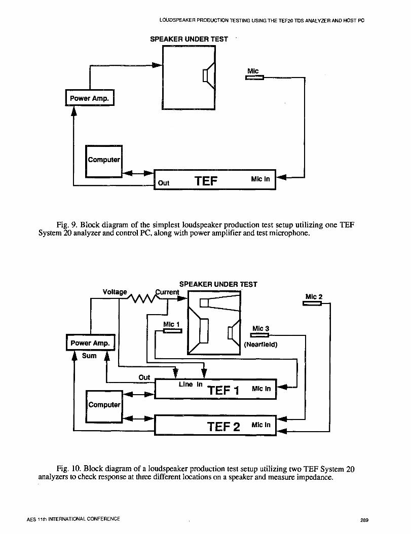
The limits can be based on a singlemeasurement of a standard speaker. In this 3.1. Typical Hardware Setupssituation, an envelope of arbitrary limits can be Figure 9 shows the minimum possibleformed around the standard's measured loudspeaker production test setup which utilizes aresponse. The envelope shape then rises and falls single TEF System 20 analyzer with controlwith increases and decreases in the response of computer, a single-channel power amplifier, andthe standard, precision test microphone. Figure 10 shows a
more complex setup using two analyzers, apower amplifier, and three test microphones.
2.2.3. Limits Determined by Batch This latter setup allows tests to be made fromStatistics three separate microphone locations, along with
connections which measure the input voltage andA batch of loudspeakers can be measured input current (and hence impedance) of theand then a statistical analysis of the results can
produce a specific envelope. Various statistical loudspeaker.analysis parameters such as mean, standarddeviation, and maximum/minimum are available 3.2. Repeatability: Humans vs
Automated Testingto create the limit envelope. Several tools areavailable that aid in the creation of these To compare the repeatability of human-envelopes including, smoothing, offsetting of operated (and judged) testing versus computer-curves, and direct entry of desired data values, operated automated testing, a batch of 100
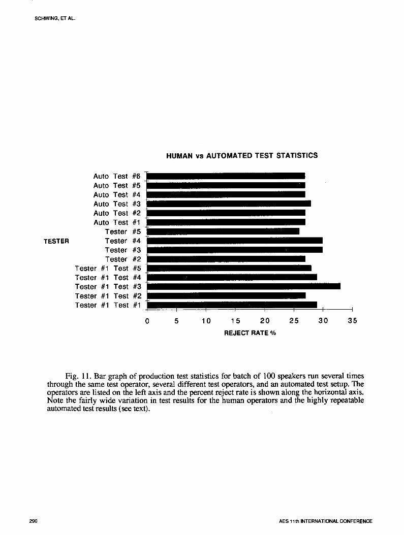
loudspeakers was repeatedly tested as follows:2.2.4. Limits Determined by Rerun five different times by the same experiencedof Batch Measurement Data in Mock human tester, once byfourdifferentexperiencedProduction Runs human testers, and six times by a completely
computer-operated automated test setup.The final way of creating pass/fail limits The test consisted of only a frequency
and envelopes is much more involved than the response measurement with envelope limits and aprevious three methods. It depends on creating a low-frequency rub-buzz test. The human testcomplete target production test (TST File) which consisted of a manually operated responseconsists of several individual measurements with measurement with the curve appearing on anassociated pass/fail criteria's (STN Files), and analyzer screen. The operator would then judgethen running a batch of typical (not specially the response to see if it fit within limits whichselected) production speakers (say 50 or 100) were drawn on the face of the analyzer. This waswith the complete raw measurement data for each followed by a manual sinewave sweep with thespeaker being stored to disk. The completeproduction test run can then be rerun (or replayed operator listening for rubs and buzzes.automatically) offline to determine an overallpass/fail rate. The pass/fail limit envelopescontained in the original test can then be finetuned to yield an acceptable overall reject rate.
282 AES 11th INTERNATIONAL CONFERENCE

LOUDSPEAKER PRODUCTION TESTING USINGTHE TEF20 TDS ANALYZER AND HOST PC
The computer operated test was somewhat System 20 or TEF System 20 HI), generalsimilar but both tests were done without human purpose measurement software (Sound Lab), andinvolvement. In the computer operated rub-buzz the production test software (Speaker Test).test, a repetitive fast sweeping low-frequency Power amplifiers and test microphones aresinewave was sent to the loudspeaker and its separately available.acoustic output was analyzed on a spectrumanalyzer to look for higher-frequency extraneous 5. S UM M A R Yspectral energy. This paper has described a relatively low-
Figure 11 shows the results of these tests in cost easy-to-operate computer-operateda bar graph format. The individual testers are automated loudspeaker production test systemlisted on the vertical axis and the measured reject that can objectively test many differentrates are shown along the horizontal axis. The operational parameters and determine overalltop six testers are the automated ones while the pass/fail statistics. The basic system can beremaining are the human judged tests. As can be expanded to quite complex test setups. It wasseen, the automated tests are quite consistent shown that automated testing can greatly improve(maximum variation of only 1% in reject rate) the testing consistency, as compared to human-while thehumanjudgedtestsexhibitsignificantly judged tests. This allows bad units to bemore variability (variation of 7% in reject rate), consistently rejected and good units to be passed.Even the tester retesting the same batch ofspeakers had a variation of 5 percentage points!This implies that with human judged tests, a 6. REFERENCESsignificant number of bad units will be shipped [1] R. C. Heyser, "Acousticalwhile a number of good units will be rejected. Measurements by Time-Delay Spectrometry," J.
Audio Eng. Soc., vol. 15, pp. 370-382 (1967
4. SYSTEM PRICES October).[2] J. Vanderkooy, "Another Approach toAs of May 1, 1992, prices for the serial- Time-Delay Spectrometry," J. Audio Eng. Soc.,
port version of the TEF System 20 Speaker Test vol. 34, pp. 523-538 (1986 July/August).system are $5,850, while the high-speed parallel- [3] D. B. Keele Jr., "TDS: Application ofport version is $6,500 (FOB Elkhart, Indiana, Technology," Sound and Video Contractor,USA). This price includes hardware (one TEF (1985 September).
,AES 11th INTERNATIONAL CONFERENCE 283

ol:z:l
r_
=_
_._o"'"_
_...1.__
__
._
o_o
'._
mo
_[_
__'
·,..__
,._._
_I}q
"l:J
m_
·__
_,_
_'_
_
284A
ES
11thIN
TE
RN
AT
ION
AL
CO
NF
ER
EN
CE

LOUDSPEAKERPRODUCTI'ONTESTINGUSINGTHETEF20TDSANALYZERANDHOSTPC
Hardwaresiificatiom.This section contains specificationsand performance data for Indicatorsand Jlghtsthe TEFSystem 20 analyzer. Applicationssoftware, suchasSound Lab, may not use all the featureslisted here. Level Green LED,brightness proportional
to input levdProcessor Overload Red LED,brightness proportional toMemory RAM64Kx24 overloadlevel
Non-programmableROM,32Kx 24 bits Power Red LEDFieldprogrammable ROM,8Kx 24 bits
Digitalsignalprocessor Motorola XSPS6001ZL27 PhysicalDigital-to-analog Weight t0 lbs. 7 oz. (4.73 kg)converter 16bits, 8 timesover-sampled Dimensions 17"x 12-3/8" x 1-3/4".Analog-to-digital (43.2 cm x 31.4 cm x 4.4cm)converter 16bits,64 times over-sampled Reset switch Momentary-action, recessedpush*
(synchronouslysampled2-channel) buttonon thefront panelData format IEEEfloating point Power switch Rockerswitch on the back panelEight-bitmantissa, Operating temperature 32' to 130'F (0_to SS'C)
24-bit exponent Cooling Ventilation slots on file top and
E]ecMcaJspecifications bottom for convection coolingCommunication
Frequency and phase response measuredat the line-level input, interface R5-232(19.2 and 57.6kilobaud)dc coup/ed.Frequent' response 10Hzto 21kHz, +-0.2dB ACpower 100,120, 220 or 240 volts rms
48-440 Hz,30 watts
Phase response I0 Hzto 21kHz,+-1.0 Optional high speed 8 bit ISAto DSPhost interface bussDynamicrange 96dBTHD+ noise -85dBat 1kHz Computer requirements for Ks
The PC version of applications software will run on any MS-Trigger connector DOS-basedsystem, version 3.1 or higher, with EGAor _v'GAConnector type Four-pinDIN,mates with RadioShack graphics. Forsystems with acceptable performance levels, we
part number 274-007 make the followingsuggestions:Voltagelevel ITL compatible, 0 and Svdt logic Microprocessor 20MHz 386 with math coprocessorMaximum current Sourceand sink current no more than RAM Two megabyte recommended.
24mA 1megabyteminimumMicrophone input Monitor VGAhigh resolution with color recom-TEF20 has two microphone-level inputson the front panel, mended, EGAh/Th rezolution monitorEither input can be selected from software, or VGAmedium resolution mimiruum
Coupling Inputcouplingisaconly.' Harddisk 80megabvterecommendedConnector Three-pin XLR..pin 2 "+",pin 3 "-" 40 megabyte mimhnumGain 0-60 dB in 4 dBsteps, sofm'arecontrol Interface One unassigned RS-232serialport,Inputimpedance 6.8Ikfi capableof.57.6kilobaudMaximum input Operating system Version3.1 or newervoltage 1volt rms Printers supported Epson FX,Epson LQ,and HPlaser iet
Polarizing voltage Internal iumper selects0 or +48volts Computer requirements forMacintosh
Lineinput AnyMacintoshIIfamilyofcomputersorMacintoshSE30.
TEF20 has two line-level inputs on the front panel. Either Finder and system 6.0.3 or newerinputcanbeselectedfromsoftware. RAM 2 megabyte4 megabytewithCotmector Front panel BNC MultiFinder)Input impedance DC=2N.lt) Hard disk 80 megabyte recommended, 40
AC=IN.ED megabyte minimum
Coupling Frontpanel switch forac or dc coupling Printers supported ,411Apple printers includingMaximuminput voltage 1volt nns Laserwriterseries
Testoutput SpecifichardwarerequirementsareavailablefromTechron.'Macintoshisa registeredtrademarkof AppleComputer,Inc.Connector BNC
Level 1voltrrm(±Smillivolts)
Adjustablewith front panel control JmmQ_m,,Source impedance Front panel switch sets source :;_,, system
impedance to zero or SOohmsP.O.Box ]O00/ Elkhort,IN465154000219-294-8300/Fox21%294-8329TEFSystemActionLine1'800-833-8575
Fig. 2. Hardware specifications of the TEF System 20.
AES11thINTERNATIONALCONFERENCE 285

SCHWING, ET AL
i
naer;_ TEST ,_za_
1) Select Test
2) Do Test
3) Set Delag
4) Set AMp Level
7) Stat ist ics
8) Change Co_
9) S top Test
O) QuitT rend
_. Failed
[_]FIn _ No. Tested
Fig. 3. Startup screen for operator mode.
ST File Measure '-_ Display Input
FREQUENCY STANDARD
SWEEP:
Start Frequency (Hz): lO0
Stop Frequency (Hz): 10000
Sweep Time (sees): 1.016
Receive Dela_ (_secs): O.OOOO
RESOLUTION:
Frequency (Hz): 98.7
Distance (feet): LX.4
Tine (nsecs): 10.1
S_eep Rate (Hz/sec): 9745.3
Bandwidth (Hz): 98,7
No. Of SaMples _ other
Best Freq. Resolution _ Off
Input ParaMeters
Test FREQUENCY
S_oothing UDDer 0,0Data O.OLower O.O g
Offset UDDer 0.00Lower 0.O0
Fail Margin of 0.00 in a sequence of 0
Fig. 4. Data entry screen for the frequency response parameters for doing a magnitude vsfrequency test standard.
286 AES 11_ INTERNATIONAL CONFERENCE

LOUDSPEAKER PRODUCTIONTESTING USING THE TEF20 TDS ANALYZER AND HOST PC
I _!,= 1 I_'=1 _T =.lk _r:.l i_.--!m
T ire Response (ETC)
Frequency Response (TDS)
1 _ _ L"[=_.t-aa _11 II :'1_
Harnonic Tracking (STN)
IMpedance (STN)
Phase (STN)
Do FFT (STN}
HarMonic Distort ion (STN)
THD (STN)
THD+N (STN)
Test Sequence (TST)
5. Engineer Mode Parameters Menu with Frequency standard entry selected (the results ofselecting this entry are shown in the previous Fig. 4).
ST File Measure '-_ Displa_ Input
HEW TEST
ZTRY .TST
Creator
Date/TiMe : 02/19/1992 17:51:27
DESCRIPTION
Line I :
Line 2 :
Test Sequence OutoutPass Fail On Fail
Standard Scr Osk Prn # Scr Dsk Prn _ IQuit R_t Pause
1.
2.
3.
4.
5.
6.
7.
8.
9.
10.
RecoMmended Amp Level = 82.5
Sa.pla I out of each 0 tested (0 : no sa._les)
AutoSave Statistics _ Off
Saue (press enter)
Fig. 6. Results of selecting Test Sequence entry in Parameters Menu. This entry screenallows the test engineer to define the sequence of individual measurements that make up a completeproduction test. Up to 20 different measurements can be incorporated.
AES 11th INTERNATIONAL CONFERENCE 287
SCHWING, ET AL.
Do TiMe Test (ETC) F5
Do Freq Test (TDS) F6 Create Window B_:
Do HarMonic Tracking Batch:
Do IMpedance Maxim_u_/M in iMUM ShftF7
Do Phase Standard Deviation CtrlF?
Do EFT
Do HarMonic Distortion
Do THD
Do THD+N
Do Test Sequence F8
REPLACES CURRENT DATA
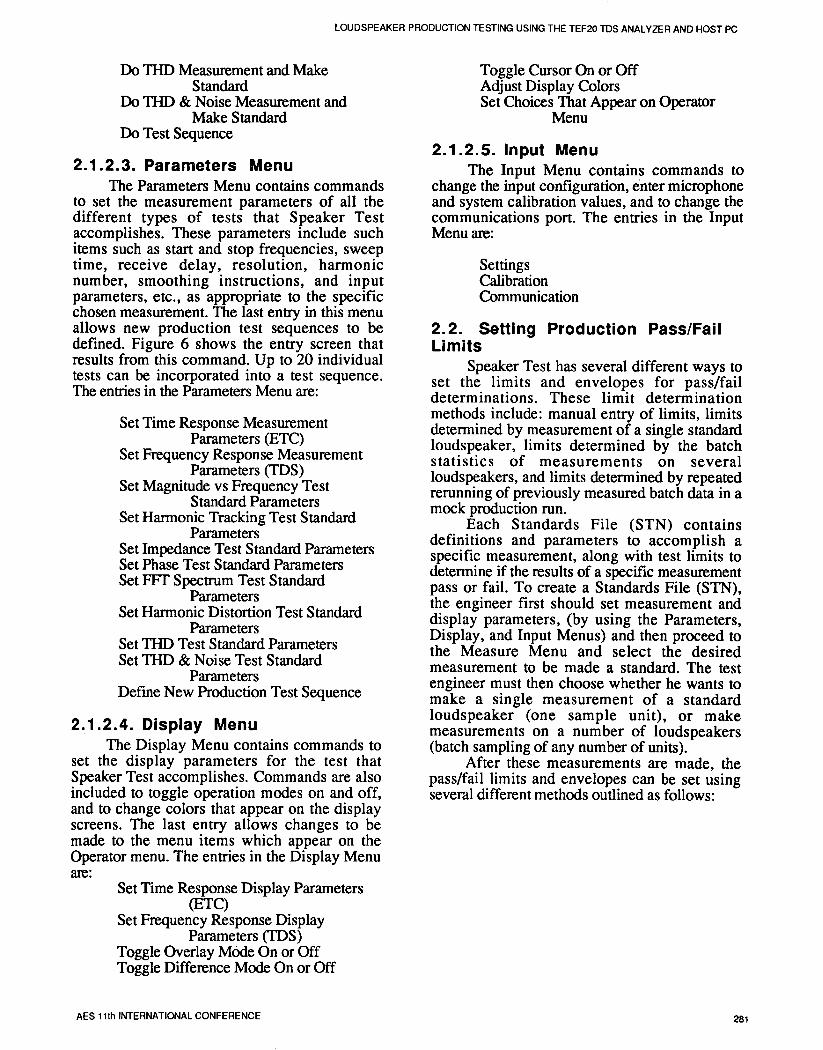
Fig. 7. Pull down of the Engineer Mode Measure Menu with the Do Frequency Test submenu selected. This entry allows a single or multiple batch test of frequency response magnitudevs frequency. In the batch mode, statistics can be gathered to track maximum/minimum or standarddeviation on a batch of speakers to allow easy establishment of upper and lower pass/fail limitenvelopes.
TiMe Response (ETC)
Overlay Ctrl-F2 On
Difference A 1t-F2 On
Cursor F2 On [i][_r_
Adjust Displa_ Colors
Operator Menu
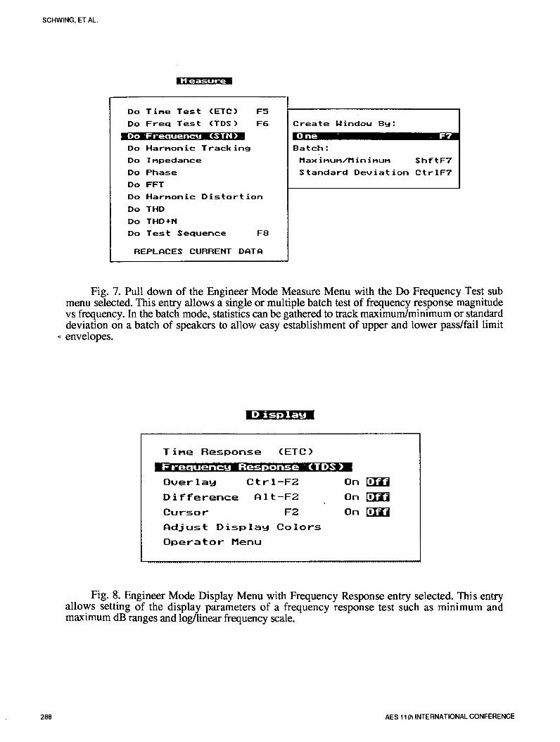
Fig. 8. Engineer Mode Display Menu with Frequency Response entry selected. This entryallows setting of the display parameters of a frequency response test such as minimum andmaximum dB ranges and log/linear frequency scale.
288 AES 11th INTERNATIONAL CONFERENCE
LOUDSPEAKER PRODUCTION TESTING USING THE TEF20 TDS ANALYZER AND HOST PC
SPEAKER UNDER TEST
v [_ MiC
I Power Amp. I
C°mputerb_ Out TEF Mic In _-
Fig. 9. Block diagram of the simplest loudspeaker production test setup utilizing one TEFSystem 20 analyzer and control PC, along with power amplifier and test microphone.
SPEAKER UNDER TEST
Voltage Mic2
MIc 1Mic3i,,,,=,,=,=l
PowerAmp. (Nearfield)
Sum
OutLine In
TEF 1 Mic In
Computer
TEF 2 MicIn
Fig. 10. Block diagram of a loudspeaker production test setup utilizing two TEF System 20analyzers to check response at three different locations on a speaker and measure impedance.
AES 11th INTERNATIONAL CONFERENCE 289
SCHWING, ET AL.
HUMAN vs AUTOMATED TEST STATISTICS
Auto Test #6Auto Test #5Auto Test #4Auto Test #3Auto Test #2Auto Test #1
Tester #5TESTER Tester #4
Tester #3Tester #2
Tester #1 Test #5Tester #1 Test #4Tester #1 Test #3Tester #1 Test #2
Tester #1 Test #1 _
0 5 10 15 20 25 30 35
REJECT RATE %
Fig. 11. Bar graph of production test statistics for batch of 100 speakers run several timesthrough the same test operator, several different test operators, and an automated test setup. Theoperators are listed on the left axis and the percent reject rate is shown along the horizontal axis.Note the fairly wide variation in test results for the human operators and the highly repeatableautomated test results (see text).
290 AES 11th INTERNATIONAL CONFERENCE