LOSSNAY HANDBOOK...VL-100U5-E VL-100EU5-E 50 220 Hi 30 100 73 36.5 7.5 Lo 13 55 80 24 230 Hi 31 105...
24
Warning: Repair work must be performed by the manufacturer, its service agent or a similarly qualified person in order to avoid hazards. LOSSNAY HANDBOOK MODELS VL-100U5-E VL-100EU5-E November 2016 No. U190-A Nameplate
Transcript of LOSSNAY HANDBOOK...VL-100U5-E VL-100EU5-E 50 220 Hi 30 100 73 36.5 7.5 Lo 13 55 80 24 230 Hi 31 105...

Warning:Repair work must be performed by the manufacturer, its service agent or a similarly qualified person in order to avoid hazards.
LOSSNAY
HANDBOOKMODELS
VL-100U5-EVL-100EU5-E
November 2016 No. U190-A
Nameplate

Contents
1. Safety precautions ....................................................................... 3 2. Names and functions of components .......................................... 4 3. Specifications .............................................................................. 4 4. Outside dimensions ..................................................................... 5 5. Electrical wiring diagrams ............................................................ 6 6. Troubleshooting ........................................................................ 7-8 7. How to call ................................................................................... 9 8. Service inspection list .................................................................. 9 9. Overhauling procedures ....................................................... 10-15 10. Parts catalog ........................................................................ 16-24 VL-100U5-E .................................................................... 17-20 VL-100EU5-E ................................................................. 21-24

─ 3 ─
Read the following precautions thoroughly before the maintenance, and then inspect and repair the product in a safe manner. The types and levels of danger that may arise if the product is handled incorrectly are described with the warning symbols shown below.
Warning
Modification is prohibitedDo not modify the unit.
(Failure to heed this warning may result in electric shock, fire and/or injury.)
Electric shockIf you must inspect the circuitry while the power is on, do not touch the live parts.
(Failure to heed this warning may result in electric shock.)
Check insulationUpon completing repair work, always measure the insulation resistance. Verify that it is at least 10 MΩ (with a 500 V DC insulation resistance tester), and then turn on the power.
(Inadequate insulation may result in electric shock.)
Incorrect handling of the product may result in serious injury or death.
Caution Incorrect handling of the product may result in injury or damage to properties including buildings and equipment.
Proper electric workUse the electric wires designated for electric work, and conduct electric work in accordance with the "Electric Installation Engineering Standard", the "Indoor Wiring Regulations" and the installation instructions.
(Improper connection or wiring installation may result in electric shock and/or fire.)
Replace damaged and/or degraded partsBe sure to replace the power cord and lead wires if they are damaged and/or degraded.
(Failure to heed this warning may result in electric shock and/or fire.)
Use proper parts and toolsFor repair, be sure to use the parts listed in the service parts list of the applicable model and use the proper tools.
(Failure to heed this warning may result in electric shock, fire and/or injury.)
Caution againstelectric shock
Prohibited
Be sure to follow this instruction.
Turn off the power supplyBe sure to unplug the power cord, or shut off the circuit breaker before disassembling the unit for repair.
(Failure to heed this warning may result in electric shock.)
Make sure that the product operates properly upon completion of repair. Clean the product and the surrounding area, and then notify the customer of the completion of repair.
Caution for injuryDo not work at a location where you do not have a sure footing.
(Failure to heed this caution may result in a fall.)
Request for repair● Inspect the grounding, and repair it if it is incomplete. Make sure that a power supply isolator or an overload
protection device is installed, if it is not installed, recommend the dealer to install one.
Be sure to follow this instruction.
Wear glovesWear gloves when servicing.
(Failure to heed this caution may result in injury to your hands from sharp metal or other edges.)
1. Safety precautions
Be sure to follow this instruction.
Be sure to follow this instruction.
Be sure to follow this instruction.
Be sure to follow this instruction.Prohibited

─ 4 ─
2. Names and functions of components
Filter frame
Lossnay Core (Heat exchanger)
Core handle
Louver Filter stopper Front panel
Shutter knob
Power plug(VL-100U5-E only)
Pull cord(VL-100U5-E only)
Exhaust air filter
Outside air filter(Replacement filter)
3. Specifications
The testing methods are based on Japanese Industrial Standard B 8628.
Model Power supply
NotchPower con-sumption
(W)
Air volume(m3/h)
Temperatureexchange
efficiency (%)
Sound level(dB)
Weight(kg)Frequency
(Hz)Voltage
(V)
VL-100U5-EVL-100EU5-E
50
220Hi 30 100 73 36.5
7.5
Lo 13 55 80 24
230Hi 31 105 73 37
Lo 15 60 80 25
240Hi 34 106 72 38
Lo 17 61 79 27
60 220Hi 34 103 73 38
Lo 17 57 80 25
About the filtersFeatures
Exhaust air filterExhaust air
side The filter prevents clogging of the internal parts.
Outside air filter(Replacement filter)
(P-100F5-E: Optional parts)
Supply air side
When Lossnay takes in outside air to a room, the filter collects dust, sand, pollen or the likes from outside air.Note: Some fine particles or tiny insects may pass
through the filter. The high performance filter is recommended for higher collecting effect.
Outside air filter can be replaced with the following high performance filter.
High performance filter(Optional parts)
(P-100HF5-E)
Supply air side
The filter collects dust more efficiently than the outside air filter.Note: When using the high performance filter, install it
in the filter frame without using the filter stopper.

─ 5 ─
4. Outside dimensionsVL-100U5-E
Unit (mm)VL-100EU5-E
Unit (mm)

─ 6 ─
5. Electrical wiring diagramsVL-100U5-E
VL-100EU5-E

─ 7 ─
6. Troubleshooting Work precautions
• When servicing, be sure to recreate the malfunction two or three times before starting repairs.• When servicing, always keep proper footing.• When servicing, always unplug the power cord from the outlet, or turn off the circuit breaker. Sufficient care
must be taken to avoid electric shock or injury.• Always connect the power wires properly.
(1) Service FlowchartAfter checking the check items below, follow the troubleshooting 1 and 2 for servicing.
Check items
1 Condition of trouble
2 Frequency of trouble:The date of starting operation and occurrence of trouble
3 With or without working drawings:Equipment, wiring
Troubleshooting 1 Lossnay does not operate, or it stops by itself.
Check the initialization checklist from installation to operation ((2) Table 1).
Troubleshooting 2 Lossnay operates irregularly.
Check the Lossnay checklist ((2) Table 2) and Basic checklist for the major components ((2) Table 3).
Troubleshooting 1 Lossnay does not operate, or it stops by itself.
(2) Checklist
1 Initialization checklist from installation to operation (Table 1)
No. Error Checkpoint1 The Lossnay operation is
disabled or improper.Lossnay stops irregularly.
Check the main power connection.<For VL-100U5-E>• Is the power plug connected to the power supply of rated voltage?<For VL-100EU5-E>• Is the rated voltage supplied to the terminal block?• Is there a poor connection?
Troubleshooting 2 Lossnay operates irregularly.
2 Lossnay checklist (Table 2)
No. Error Cause Action1 The shutter
does not open.The shutter does not close.
Is there any foreign matter or obstruction around the shutter?
Remove it.
2 The fan does not rotate.
Do the fan blades touch other parts? Check for an abnormal area.Replace the parts of the abnormal area.
Is there any foreign matter around the fan? Remove it.Is there something wrong with the motor? Check the basic checklist for the major
components (Table 3).3 An unusual
noise comes from the fan.
Is there any foreign matter around the fan? Check around the fan.
Can you rotate the fan manually? No: Replace the motor.Is there an odd feeling when rotating the fan?
Yes: Replace the motor.
─ 8 ─
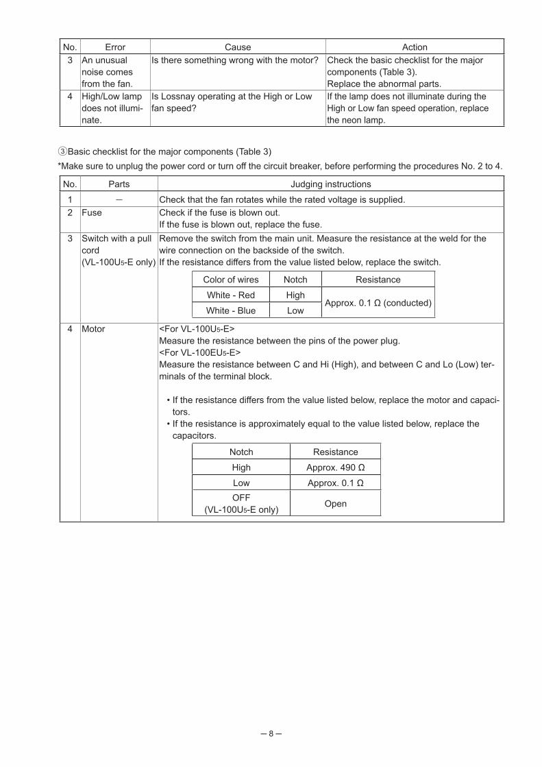
No. Error Cause Action3 An unusual
noise comes from the fan.
Is there something wrong with the motor? Check the basic checklist for the major components (Table 3).Replace the abnormal parts.
4 High/Low lamp does not illumi-nate.
Is Lossnay operating at the High or Low fan speed?
If the lamp does not illuminate during the High or Low fan speed operation, replace the neon lamp.
3 Basic checklist for the major components (Table 3)*Make sure to unplug the power cord or turn off the circuit breaker, before performing the procedures No. 2 to 4.
No. Parts Judging instructions
1 Check that the fan rotates while the rated voltage is supplied.2 Fuse Check if the fuse is blown out.
If the fuse is blown out, replace the fuse.3 Switch with a pull
cord(VL-100U5-E only)
Remove the switch from the main unit. Measure the resistance at the weld for the wire connection on the backside of the switch.If the resistance differs from the value listed below, replace the switch.
Color of wires Notch Resistance
White - Red HighApprox. 0.1 Ω (conducted)
White - Blue Low
4 Motor <For VL-100U5-E>Measure the resistance between the pins of the power plug.<For VL-100EU5-E>Measure the resistance between C and Hi (High), and between C and Lo (Low) ter-minals of the terminal block.
• If the resistance differs from the value listed below, replace the motor and capaci-tors.
• If the resistance is approximately equal to the value listed below, replace the capacitors.
Notch Resistance
High Approx. 490 Ω
Low Approx. 0.1 ΩOFF
(VL-100U5-E only) Open

─ 9 ─
7. How to callSymptom Remedy
The incoming air feels cold. 1 Stop the operation, and close the shutter.2 Adjust the louver in a horizontal position.3 Change the fan speed to Low.
Unusual noise occurs.(Noise became louder.)
1 Clean the filters.2 Securely attach the front panel and filters.
Small insects intrude into the unit. 1 Place the filter (outside air filter) properly inside the filter frame.2 Replace the filter (outside air filter) with the high performance filter
(optional parts).
8. Service inspection listLocation Inspection Item Check Result
Electric wiring
Are the power lead wires securely connected to the terminal block? (VL-100EU5-E)
Is the wiring correct? (VL-100EU5-E)
Appliance
Is the main unit securely mounted?Does Lossnay operate as described in the Operating Instructions when oper-ating the switch?
Is the fan operating?
Does the shutter work?
Does Lossnay operate without abnormal vibration or noise?
─ 10 ─
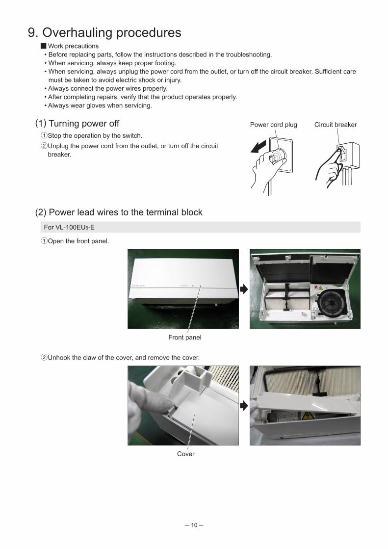
(2) Power lead wires to the terminal block
Front panel
Power cord plug Circuit breaker(1) Turning power off1 Stop the operation by the switch. 2 Unplug the power cord from the outlet, or turn off the circuit
breaker.
For VL-100EU5-E
2 Unhook the claw of the cover, and remove the cover.
Cover
1 Open the front panel.
9. Overhauling procedures Work precautions
• Before replacing parts, follow the instructions described in the troubleshooting.• When servicing, always keep proper footing.• When servicing, always unplug the power cord from the outlet, or turn off the circuit breaker. Sufficient care
must be taken to avoid electric shock or injury.• Always connect the power wires properly.• After completing repairs, verify that the product operates properly.• Always wear gloves when servicing.

─ 11 ─
3 Unscrew the terminal block (TB) case cover clamping screw (one PT screw 4 × 8, indicated by ), and remove the TB case cover.
TB case cover
4 Loosen the screws of the terminal block (three screws, indicated by ) with a screwdriver, and disconnect the power lead wires.
(3) Main unit1 Unscrew the main unit clamping screws (two black PTT screws
4 × 8, indicated by ).2 Slightly lift the main unit, and then take it down.
Power cord
Main unit
(4) Front panel • Open the front panel all the way (approx. 90 degrees), and pull it up to unhook the claws (indicated by ).
PrecautionPay attention not to damage the front surface of the removed panel.
Front panel
*The illustration shows VL-100U5-E.

─ 12 ─
(5) Lossnay core • Hold the core handle, and pull it out in the direction of the arrow while holding down the hook part.
Hook part
Core handle
<Reassembly procedure> • When installing the Lossnay core, first fit the lower part of the core handle (indicated by “a”) into "b" position
of the front casing, and then hook the ledge of the core handle to the concave portion of the front casing (indicated by ).
<Installed state>
(6) Front casing1 Unscrew the screws (six PTT screws 4 × 14, indicated by ).
2 Unscrew the lamp cover clamping screw (one PTT screw 4 × 14, indicated by ), and remove the lamp cover.
a
b
Ledge
Front casing
Core handle
Reassembly precautionCheck that both edges of the Lossnay core (indicated by ) are securely fitted.
Lamp cover

─ 13 ─
3 Remove the neon lamp from the front casing.4 Pass the neon lamp through the hole of the front casing, and then remove the front casing.
Neon lamp
(7) Air exhaust (EA) fan1 Remove the special nut (8) and tab washer, and then remove
the EA fan.
Special nut (8)
2 Remove the special (spl) washer (40 mm in outer diameter).
Spl washer
Reassembly precautionBe aware of the size difference between each washer for EA fan and SA fan.Incorrect installation may cause unusual noise.
EA fan
Hole of the front casing
Tab washer

─ 14 ─
4 Remove the special (spl) washer (8) (16 mm in outer diameter).
Spl washer (8)
Reassembly precautionBe aware of the size difference between each washer for EA fan and SA fan.Incorrect installation may cause unusual noise.
(9) Motor • Unscrew the screws that clamps motor and lead cover (six PTT
screws 4 × 10, indicated by ), and then remove the motor.
Reassembly precautionWhen installing the lead cover, make sure to place it under the motor (indicated by ).
2 Turn the motor fix plate upside down, and put it on the main unit.3 Remove the special nut (8) and tab washer, and then remove
the SA fan.
(8) Air supply (SA) fan1 Unscrew the motor fix plate clamping screw (one PTT screw 4 ×
14, indicated by ).
SA fan
Lead cover
Motor fix plate
Motor
Special nut (8) Tab washer

─ 15 ─
(10) Terminal block case (TB case)1 Unscrew the TB case clamping screw (one PT screw 4 × 8, indi-
cated by ), and remove the TB case.
TB case
2 Unscrew the TB fix plate clamping screws (two PTT screws 4 × 8,indicated by ), and remove the TB fix plate.
TB fix plate
(11) Fan casing • Remove the fan casing (made of styrene foam).
Fan casing Casing assembly
When reassembling Reassemble the unit in the reverse order of disassembly. After reassembly, always make a test run to make sure that the unit operates properly.

─ 16 ─
10. Parts catalog
Please note the following when using the parts catalog.
1. When ordering parts, always indicate the part number, part name, and the number of parts required.
2. Parts are not always available, and it may take time for you to receive them.3. There may be specification improvements.4. Parts marked are critical for safety. To maintain safety and performance, always
replace these parts with the parts prescribed.
Abbreviation Description
PC screw Cross recess fl at head machine screw
PRC screw Cross recess oval head machine screw
PP screw Cross recess pan head machine screw
SW · PP screw Cross recess pan head screw with spring washer
PPT screw Cross recess tapping screw
PCT screw Cross recess fl at head tapping screw
PTT screw Cross recess truss head tapping screw
PT screw Cross recess truss head machine screw
SET screw Slotted head stop screw
SQ · SET screw Square head stop screw
P · SET screw Pan head stop screw
PMT screw Primer truss head screw
HS · SET screw Hexagon head stop screw
P · R · W screw Cross recess round wood screw
P · C · W screw Cross recess fl at head wood screw
P · R · C · W screw Cross recess round and fl at wood screw
R · W screw Slotted round wood screw
PW · PP screw Cross recess pan head screw with small washer
SW-PW · PP screw Cross recess pan head machine screw with spring washer and fl at washer
Description of screw abbreviations Screw 4 × 16
Screw diameter Length

─ 17 ─VL-100U5-E
3029
28 2035
22 2223 24
25
26
26
32
27
34
11
1315
15
16
14
171221
1
2 3
4
56
67
8
910
19
18
33
31
12
12
20
1819
VL-100U5-E

VL-100U5-E
1 Front panel Y36 004 721 12 Lossnay core Y36 004 723 1
3 Core handle Y36 004 722 14 Cover Y36 004 709 15 Front casing Y36 004 707 16 PTT screw 4×14 H00 000 333 87 PTT screw 4×10 M32 013 027 18 Filter Y36 004 717 1
9 Lamp cover Y36 004 711 110 Neon lamp Y36 004 290 1
11 TB case cover Y36 004 710 112 PT screw 4×8 H00 000 349 313 TB case Y36 004 708 114 Cord band K83 170 228 1 White15 Crimp cap K82 181 240 6 CE1(CE-100V)16 Cord clamper M35 855 223 117 Cord clamper M35 830 223 118 PT screw 4×8 BS H00 011 008 319 Spg. washer (4) H00 056 075 320 PTT screw 4×8 H00 000 487 621 Cord clip X31 981 223 122 Cord clip D40 094 227 223 Fuse Y36 004 280 1 1A・250V24 PPT screw 3×10 H00 000 676 125 Fuse holder Y55 001 281 126 Cord bush M45 649 226 227 TB fix plate Y36 004 712 128 PPT screw 4×10 H00 000 471 129 Switch Y36 004 255 1 With a pull cord30 Insulator sheet M34 279 201 1
31 Capacitor case M35 768 653 132 Capacitor Y36 008 283 1 4.0μF・250VAC33 Capacitor cover M35 275 652 134 Capacitor Y36 010 283 1 1.5μF・250VAC35 Power cord Y36 004 220 1 3200㎜
RemarksNo. Name of part Parts No.Q'ty
pcs/unit
Criticalfor
safety
─18─

─ 19 ─
41
41
42
42
43
46
4748
49
50
51
53
65
66
67
69
5455 56
57 58
59 63
64
5554
68
4445
52
70
62
61
46
4748
49
50
66
20
20
60
60
44
1819
Air exhaust fan assembly
Air supply fan assembly
2 pcs.
Optional partsP-100F5-EP-100HF5-E
shows accessory parts.
VL-100U5-E

VL-100U5-E
41 Wall pipe M36 091 731 242 Pipe fix plate M36 293 707 243 Fix plate M36 100 709 144 Spl scr 3.5×32 M34 863 045 945 PTT screw 4×8 M45 502 095 2 Black46 Weather cover M36 099 707 247 Flange M36 099 708 248 Flange nut M34 231 303 249 Packing M34 519 718 250 PTT screw 4×12 D41 037 008 4 SUS51 Filter stopper Y36 004 714 152 Pipe Y36 004 706 253 Filter frame Y36 004 713 154 Special nut (8) X31 267 067 255 Tab washer M36 130 077 256 Centrifugal fan M36 265 480 1 φ17057 Spl washer M36 265 080 1 φ40 (outer dia.)58 Motor Y36 004 453 1
59 Spl washer (8) M34 365 080 1 φ16 (outer dia.)60 PTT screw 4×10 H00 000 332 661 Cord clamper R50 062 223 162 Lead cover M36 169 712 163 Motor fix plate Y36 004 715 164 Centrifugal fan Y36 004 480 1 φ17065 Fan casing Y36 004 724 166 Mounting piece M34 709 345 267 Shutter Y36 004 719 168 Shutter Y36 004 720 169 Casing Y36 004 716 170 Casing assembly Y36 004 725 1 With shutters
No. Name of part Parts No.Q'ty
pcs/unit
Criticalfor
safetyRemarks
─20─
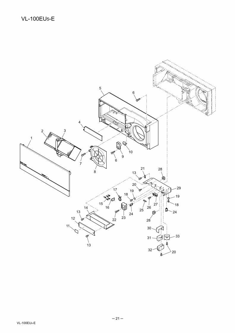
─ 21 ─VL-100EU5-E
20
22 2324 2425
2627
28
28
31
29
33
11
12
1415
16
1718
19
1321
1
2 3
4
56
67
8
910
19
18
32
30
13
13
20
VL-100EU5-E

VL-100EU5-E
1 Front panel Y36 004 721 12 Lossnay core Y36 004 723 1
3 Core handle Y36 004 722 14 Cover Y36 004 709 15 Front casing Y36 004 707 16 PTT screw 4×14 H00 000 333 87 PTT screw 4×10 M32 013 027 18 Filter Y36 004 717 1
9 Lamp cover Y36 004 711 110 Neon lamp Y36 004 290 1
11 Wiring diagram Y36 005 357 112 TB case cover Y36 004 710 113 PT screw 4×8 H00 000 349 314 TB case Y36 005 706 115 Crimp cap K82 181 240 5 CE1(CE-100V)16 Cord clamper M35 855 223 117 Cord band K83 170 228 1 White18 PT screw 4×8 BS H00 011 008 319 Spg. washer (4) H00 056 075 320 PTT screw 4×8 H00 000 487 621 Cord clip D40 134 227 122 PPT screw 3×20 H00 005 005 123 Terminal block Y36 005 242 1 3P24 Cord clip D40 094 227 225 Fuse Y36 004 280 1 1A・250V26 PPT screw 3×10 H00 000 676 127 Fuse holder Y55 001 281 128 Cord bush M45 649 226 229 TB fix plate Y36 005 707 130 Capacitor case M35 768 653 131 Capacitor Y36 008 283 1 4.0μF・250VAC32 Capacitor cover M35 275 652 133 Capacitor Y36 010 283 1 1.5μF・250VAC
No. Name of part Parts No.Q'ty
pcs/unit
Criticalfor
safetyRemarks
─22─

─ 23 ─VL-100EU5-E
41
41
42
42
43
46
4748
49
50
51
53
65
66
67
69
5455 56
57 58
59 63
64
5554
68
4445
70
62
46
4748
49
50
66
20
20
44
1819
61
60
60
Air exhaust fan assembly
Air supply fan assembly
2 pcs.
52
Optional partsP-100F5-EP-100HF5-E
shows accessory parts.

VL-100EU5-E
41 Wall pipe M36 091 731 242 Pipe fix plate M36 293 707 243 Fix plate M36 100 709 144 Spl scr 3.5×32 M34 863 045 945 PTT screw 4×8 M45 502 095 2 Black46 Weather cover M36 099 707 247 Flange M36 099 708 248 Flange nut M34 231 303 249 Packing M34 519 718 250 PTT screw 4×12 D41 037 008 4 SUS51 Filter stopper Y36 004 714 152 Pipe Y36 004 706 253 Filter frame Y36 004 713 154 Special nut (8) X31 267 067 255 Tab washer M36 130 077 256 Centrifugal fan M36 265 480 1 φ17057 Spl washer M36 265 080 1 φ40 (outer dia.)58 Motor Y36 004 453 1
59 Spl washer (8) M34 365 080 1 φ16 (outer dia.)60 PTT screw 4×10 H00 000 332 661 Cord clamper R50 062 223 162 Lead cover M36 169 712 163 Motor fix plate Y36 004 715 164 Centrifugal fan Y36 004 480 1 φ17065 Fan casing Y36 004 724 166 Mounting piece M34 709 345 267 Shutter Y36 004 719 168 Shutter Y36 004 720 169 Casing Y36 004 716 170 Casing assembly Y36 004 725 1 With shutters
─24─
No. Name of part Parts No.Q'ty
pcs/unit
Criticalfor
safetyRemarks