Lorri Grainawi Steel Tank Institute PA NISTM April 25 ... · 6.2 Single-Walled Spill Bucket –...
76
PA NISTM April 25, 2013 Harrisburg, PA Lorri Grainawi Steel Tank Institute
Transcript of Lorri Grainawi Steel Tank Institute PA NISTM April 25 ... · 6.2 Single-Walled Spill Bucket –...

PA NISTM
April 25, 2013
Harrisburg, PA
Lorri Grainawi
Steel Tank Institute

1. Introduction
2. Definitions
3. Safety
4. Tank Secondary Containment Integrity Testing
5. Piping Secondary Containment Integrity Testing
6. Spill Bucket and Containment Sump Testing
7. UST Overfill Equipment Verification, Inspection and Testing
8. Electronic Monitoring System Inspection and Testing
9. Automatic Line Leak Detectors
10. Shear Valve Inspection and Testing
11. Emergency Stop
12. Documentation
Appendices
PEI/RP1200-12 ------------------------------------------------------

Origin
Produced as an industry service
Prepared in response to requests from UST regulators, testers and operators
Represents a single authoritative source of information
1. INTRODUCTION
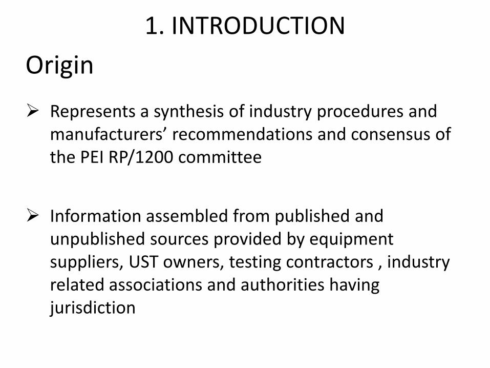
Origin
Represents a synthesis of industry procedures and manufacturers’ recommendations and consensus of the PEI RP/1200 committee
Information assembled from published and unpublished sources provided by equipment suppliers, UST owners, testing contractors , industry related associations and authorities having jurisdiction
1. INTRODUCTION

Origin
Committee is made up of representatives from:
• Equipment suppliers
• Tank owners
• Testing companies
• Industry associations
• Regulatory community
1. INTRODUCTION

Origin
In addition, the committee had the benefit of comments submitted by interested parties
• Public comment period January 24 – March 26, 2012
• 251 comments received from various parties
• RP/1200 committee considered all comments
1. INTRODUCTION

Public Comments
Comments can be made by anyone at any time via the world wide web
www.pei.org
• Publications & Resources
• Recommended Practices
1. INTRODUCTION

Origin
In instances where there were differences or omissions in material available from existing sources, the committee included its own consensus recommendations based on the practical experience of committee members
1. INTRODUCTION

Background
Spill, overfill, leak detection and
secondary containment equipment
required by regulations
In order to operate effectively and
safely, this equipment must be
maintained, inspected and tested
for proper operation on an ongoing
basis
1. INTRODUCTION

Purpose
Provide a concise summary of general guidelines for inspection and testing of __________ at UST facilities:
• Spill prevention
• Overfill equipment
• Leak detection
• Secondary containment
• Shear valves
• Emergency stops
1. INTRODUCTION

Purpose
Intended to provide recommended practices that:
• Protect human health and the environment
• Promote safe and reliable operation of UST systems
• Prevent spills and overfills associated with deliveries
• Prevent damage to property and equipment
1. INTRODUCTION

Purpose
Not intended to:
• Endorse or recommend particular materials, equipment, suppliers or manufacturers
• Discourage the development or installation of new equipment
• Discourage the development of new or improved testing procedures and equipment
1. INTRODUCTION

Scope
RP/1200 applies to UST facilities that store______
• Motor fuels
• Jet fuels
• Distillate fuel oils
• Residual fuel oils
• Lubricants
• Petroleum solvents
• Oils
• Other petroleum products
1. INTRODUCTION

Scope
Recommended Practices apply to:
• Underground storage tanks
• Connected underground piping
• Underground ancillary equipment
• Secondary containment systems
1. INTRODUCTION

Scope
Recommended Practices do not apply to:
• Aboveground storage tanks
• Mobile tanks (truck mounted refuelers)
• Dispensing equipment above grade level
• Tanks containing refrigerated liquids, liquefied petroleum gases, liquefied
natural gases or compressed natural gases
1. INTRODUCTION
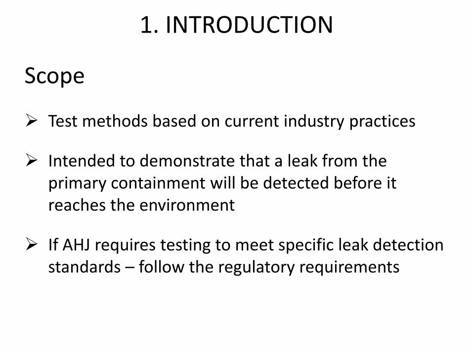
Scope
Test methods based on current industry practices
Intended to demonstrate that a leak from the primary containment will be detected before it reaches the environment
If AHJ requires testing to meet specific leak detection standards – follow the regulatory requirements
1. INTRODUCTION

Scope
RP/1200 is not meant to provide interpretation of regulatory or legislative requirements related to UST systems
1. INTRODUCTION

1. Introduction
2. Definitions
3. Safety
4. Tank Secondary Containment Integrity Testing
5. Piping Secondary Containment Integrity Testing
6. Spill Bucket and Containment Sump Testing
7. UST Overfill Equipment Verification, Inspection and Testing
8. Electronic Monitoring System Inspection and Testing
9. Automatic Line Leak Detectors
10. Shear Valve Inspection and Testing
11. Emergency Stop
12. Documentation
Appendices
PEI/RP1200-12 ------------------------------------------------------

2. DEFINITIONS
Tight Wrap Tank – A type of tank construction that consists of a primary tank wrapped by a secondary containment that is structurally supported by the primary tank.
• Interstitial space is very small
110% Containment Tank – A tank with secondary containment where the interstitial space volume is 10% of the total primary containment volume.
• Interstitial space is large

1. Introduction
2. Definitions
3. Safety
4. Tank Secondary Containment Integrity Testing
5. Piping Secondary Containment Integrity Testing
6. Spill Bucket and Containment Sump Testing
7. UST Overfill Equipment Verification, Inspection and Testing
8. Electronic Monitoring System Inspection and Testing
9. Automatic Line Leak Detectors
10. Shear Valve Inspection and Testing
11. Emergency Stop
12. Documentation
Appendices
PEI/RP1200-12 ------------------------------------------------------

3. SAFETY
“Only properly trained individuals should inspect or test overfill, leak detection and release prevention equipment.”
“These individuals are responsible for their own safety, and should take reasonable precautions to ensure the safety of facility employees, customers, and any other personnel in the work area.”
“Refer to Appendix D for related safety publications.”

1. Introduction
2. Definitions
3. Safety
4. Tank Secondary Containment Integrity Testing
5. Piping Secondary Containment Integrity Testing
6. Spill Bucket and Containment Sump Testing
7. UST Overfill Equipment Verification, Inspection and Testing
8. Electronic Monitoring System Inspection and Testing
9. Automatic Line Leak Detectors
10. Shear Valve Inspection and Testing
11. Emergency Stop
12. Documentation
Appendices
PEI/RP1200-12 ------------------------------------------------------

4. TANK SECONDARY CONTAINMENT INTEGRITY TESTING
4.1 General - Interstice may be dry or liquid filled
Dry = Vacuum Test
Wet = Hydrostatic Test
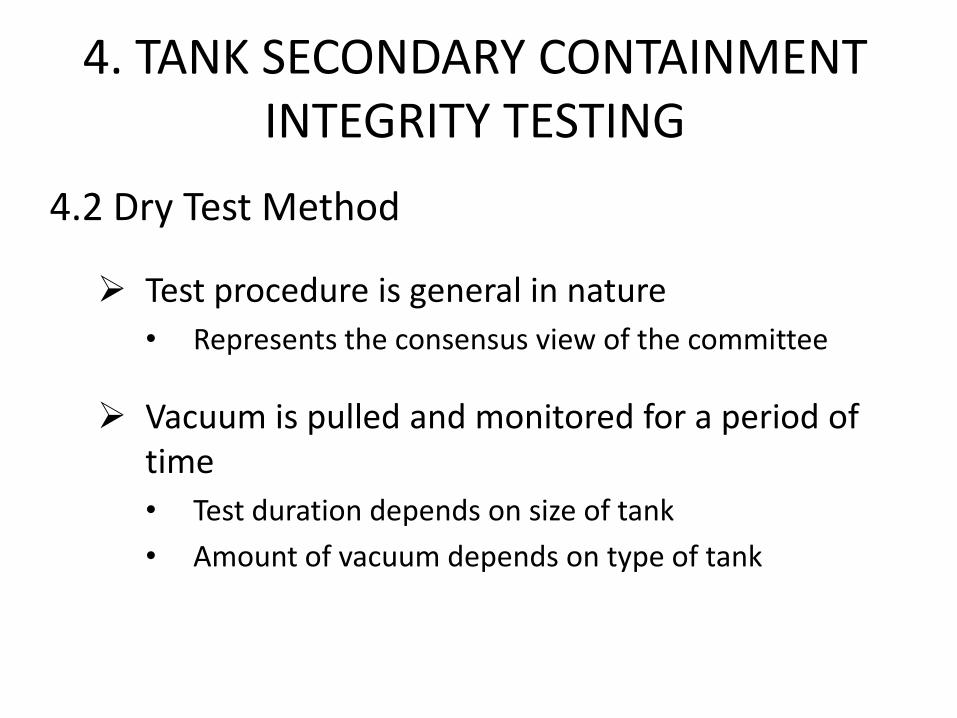
4.2 Dry Test Method
Test procedure is general in nature
• Represents the consensus view of the committee
Vacuum is pulled and monitored for a period of time
• Test duration depends on size of tank
• Amount of vacuum depends on type of tank
4. TANK SECONDARY CONTAINMENT INTEGRITY TESTING

4.2.5 Dry Test Method – Steel Tanks
Must determine if tank is a “tight wrap” or 110% containment design
• If tank is tight wrap – RP/1200 test procedure may be followed
• If tank is 110% - Follow Steel Tank Institute R012 “Recommended Practice for Interstitial Tightness Testing of Existing Underground Double Wall Steel Tanks”
4. TANK SECONDARY CONTAINMENT INTEGRITY TESTING

4.2.6 Dry Test Method – Fiberglass Tanks
May use RP/1200 test procedure
OR
Fiberglass Tank & Pipe Institute “Field Test Protocol for Testing the Annular Space of Installed Underground Fiberglass Double and Triple-wall Tanks with Dry Annular Space”
4. TANK SECONDARY CONTAINMENT INTEGRITY TESTING
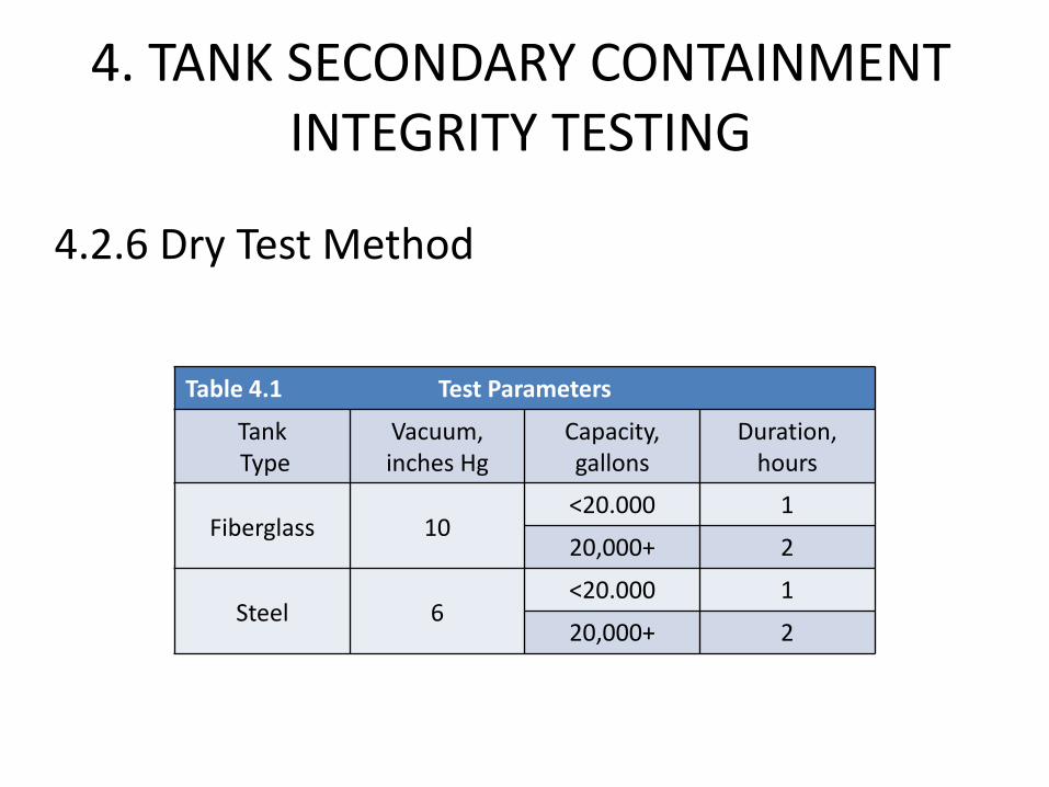
4.2.6 Dry Test Method
Table 4.1 Test Parameters
Tank Type
Vacuum, inches Hg
Capacity, gallons
Duration, hours
Fiberglass 10 <20.000 1
20,000+ 2
Steel 6 <20.000 1
20,000+ 2
4. TANK SECONDARY CONTAINMENT INTEGRITY TESTING

4.2.6 Dry Test Method
Pass = No loss of vacuum and
no ingress of fluids
Fail = Any loss of vacuum or
any ingress of fluids
4. TANK SECONDARY CONTAINMENT INTEGRITY TESTING

4.3 Hydrostatic testing
RP defers to the manufacturers’ test procedure • Variables must be considered
• Too many differences between manufacturers procedures
These tests, when conducted according to the manufacturers’ protocol, are “precision” tightness tests (0.1 gph)
Manufacturers’ checklist/data log included as appendix
4. TANK SECONDARY CONTAINMENT INTEGRITY TESTING
1. Introduction
2. Definitions
3. Safety
4. Tank Secondary Containment Integrity Testing
5. Piping Secondary Containment Integrity Testing
6. Spill Bucket and Containment Sump Testing
7. UST Overfill Equipment Verification, Inspection and Testing
8. Electronic Monitoring System Inspection and Testing
9. Automatic Line Leak Detectors
10. Shear Valve Inspection and Testing
11. Emergency Stop
12. Documentation
Appendices
PEI/RP1200-12 ------------------------------------------------------

5. PIPING SECONDARY CONTAINMENT INTEGRITY TESTING
Only tests the outer wall of double-walled pipe
• Containment sumps are tested separately
RP/1200 test procedure is general in nature (no established leak rate)

Piping interstice is pressurized with an inert gas to 5 psi and monitored for 1 hour
• Piping tested as one continuous system or in sections
• “Sealing” interstitial space of some piping systems (particularly older ones) can be problematic
5. PIPING SECONDARY CONTAINMENT INTEGRITY TESTING
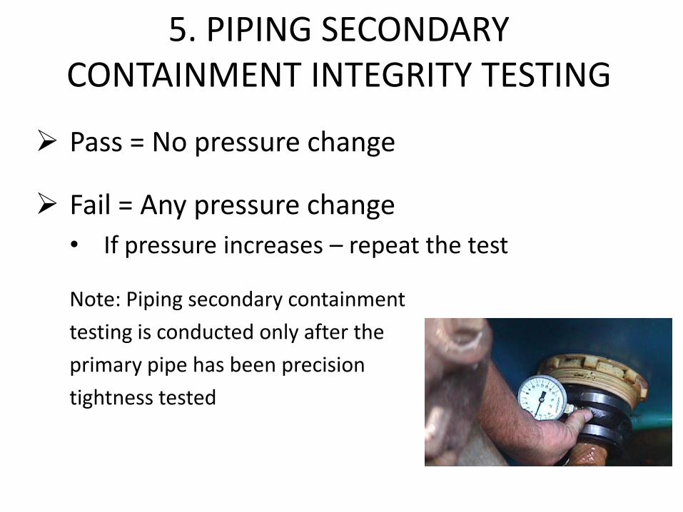
Pass = No pressure change
Fail = Any pressure change
• If pressure increases – repeat the test
Note: Piping secondary containment
testing is conducted only after the
primary pipe has been precision
tightness tested
5. PIPING SECONDARY CONTAINMENT INTEGRITY TESTING

1. Introduction
2. Definitions
3. Safety
4. Tank Secondary Containment Integrity Testing
5. Piping Secondary Containment Integrity Testing
6. Spill Bucket and Containment Sump Testing
7. UST Overfill Equipment Verification, Inspection and Testing
8. Electronic Monitoring System Inspection and Testing
9. Automatic Line Leak Detectors
10. Shear Valve Inspection and Testing
11. Emergency Stop
12. Documentation
Appendices
PEI/RP1200-12 ------------------------------------------------------

6.1 General
Spill bucket and sump testing is grouped together since the test procedure is the same
Spill buckets and containment sumps can be single-walled or double-walled
6. SPILL BUCKET & CONTAINMENT SUMP TESTING

6.1 General
Spill Buckets - Test procedures for both single and double-walled spill buckets
• Single-walled = Hydrostatic OR Vacuum test
• Double-walled = Vacuum test of interstice
Containment Sumps – Test procedure for single-walled containment sumps only
• Single-walled = Hydrostatic test
6. SPILL BUCKET & CONTAINMENT SUMP TESTING
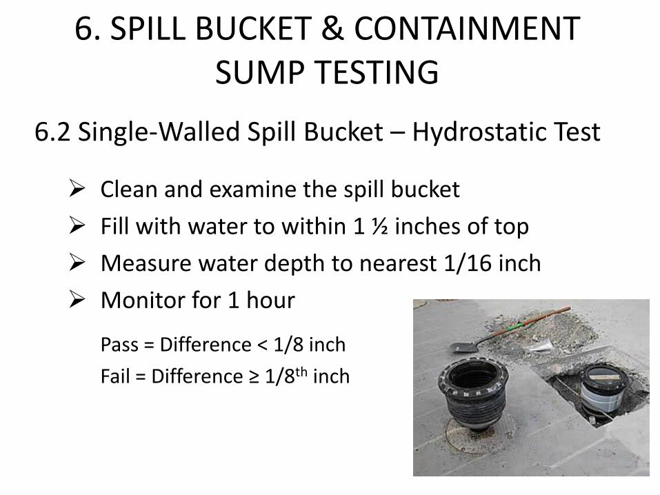
6.2 Single-Walled Spill Bucket – Hydrostatic Test
Clean and examine the spill bucket
Fill with water to within 1 ½ inches of top
Measure water depth to nearest 1/16 inch
Monitor for 1 hour
Pass = Difference < 1/8 inch
Fail = Difference ≥ 1/8th inch
6. SPILL BUCKET & CONTAINMENT SUMP TESTING

6.2 Single-Walled Spill Bucket – Hydrostatic Test
Be sure tank fill cap seals properly
Be sure drain valve seals properly
If these components don’t seal properly -
water may enter tank
Alternatively, you may temporarily
install a plumber’s plug in the fill riser
and remove/plug the drain valve
6. SPILL BUCKET & CONTAINMENT SUMP TESTING

6.3 Single-Walled Spill Bucket – Vacuum Test
Clean and examine the spill bucket
Install special test cover
Pull a vacuum of 30” H2O column
Monitor vacuum for 1 minute
Pass = Ending vacuum level ≥ 26” H2O column
Fail = Ending vacuum level < 26” H2O column
6. SPILL BUCKET & CONTAINMENT SUMP TESTING

6.4 Double-Walled Spill Bucket - Vacuum Test
Clean and examine the spill bucket
Pull a vacuum of 15” H2O column on interstice
Monitor vacuum for 1 minute
Pass = Ending vacuum ≥ 12” H2O column
Fail = Ending vacuum < 12” H2O column
6. SPILL BUCKET & CONTAINMENT SUMP TESTING

6.4 Double-Walled Spill Bucket - Vacuum Test
Testing the interstice of a
double-walled spill bucket
simultaneously tests both the
primary and secondary
6. SPILL BUCKET & CONTAINMENT SUMP TESTING

6.5 Single-Walled Containment Sump – Hydrostatic Test
Clean, examine and prepare the containment sump
Fill with water to 4” above the highest sump penetration or sidewall seam – whichever is higher
Measure water level to the nearest 1/16 inch
Monitor water level for 1 hour
Pass = Difference < 1/8 inch
Fail = Difference ≥ 1/8th inch
6. SPILL BUCKET & CONTAINMENT SUMP TESTING

1. Introduction
2. Definitions
3. Safety
4. Tank Secondary Containment Integrity Testing
5. Piping Secondary Containment Integrity Testing
6. Spill Bucket and Containment Sump Testing
7. UST Overfill Equipment Verification, Inspection and Testing
8. Electronic Monitoring System Inspection and Testing
9. Automatic Line Leak Detectors
10. Shear Valve Inspection and Testing
11. Emergency Stop
12. Documentation
Appendices
PEI/RP1200-12 ------------------------------------------------------
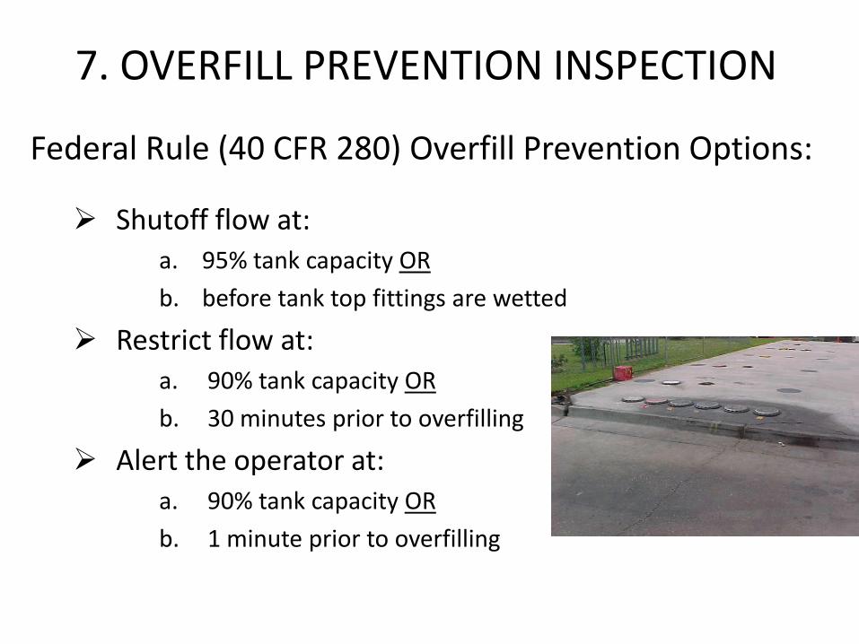
Federal Rule (40 CFR 280) Overfill Prevention Options:
Shutoff flow at:
a. 95% tank capacity OR
b. before tank top fittings are wetted
Restrict flow at:
a. 90% tank capacity OR
b. 30 minutes prior to overfilling
Alert the operator at:
a. 90% tank capacity OR
b. 1 minute prior to overfilling
7. OVERFILL PREVENTION INSPECTION

Shutoff
7. OVERFILL PREVENTION INSPECTION
Alarm
Restrict

Committee decided to develop protocols reflective of the more conservative application of the rules
Overfill prevention devices must be set to:
• Shutoff at 95% tank capacity
• Restrict flow at 90% tank capacity
• Alert the operator at 90% tank capacity
7. OVERFILL PREVENTION INSPECTION

7.1 Automatic Shutoff Devices (Flapper Valves)
Remove from the tank
Visually inspect
Manually operate valve to ensure it is functional
Measure length to ensure complete shutoff occurs when the tank is no more than 95% full
Note: Ensure that complete shutoff point occurs at 95%
7. OVERFILL PREVENTION INSPECTION

7.2 Restriction Devices (Ball Float Valves)
Remove from the tank
Visually inspect
Measure length to ensure flow restriction occurs when the tank is no more than 90% full
Note: All tank top fittings must be tight in order for the ball float valve to effectively restrict the flow
7. OVERFILL PREVENTION INSPECTION

7.3 Alert Devices (Electronic Alarms)
Electronic alarms typically part of ATG system
• Remove from the tank
• Visually inspect
• Measure length to ensure that alarm occurs when the tank is no more than 90% full
Note: Overfill alarms must provide an audible and/or visible warning to the fuel delivery driver
7. OVERFILL PREVENTION INSPECTION

1. Introduction
2. Definitions
3. Safety
4. Tank Secondary Containment Integrity Testing
5. Piping Secondary Containment Integrity Testing
6. Spill Bucket and Containment Sump Testing
7. UST Overfill Equipment Verification, Inspection and Testing
8. Electronic Monitoring System Inspection and Testing
9. Automatic Line Leak Detectors
10. Shear Valve Inspection and Testing
11. Emergency Stop
12. Documentation
Appendices
PEI/RP1200-12 ------------------------------------------------------

Test/Inspection of ATG system:
• Console
• In-tank probes
• Interstitial sensors (tanks & piping)
Test is general in nature – Not intended as calibration of ATG system
8. ELECTRONIC MONITORING SYSTEM INSPECTION

8.1 ATG Console
Verify system is properly configured (setup)
Verify all site specific parameters are correct
Verify that indicator lamps function
Verify that printer functions
Verify that LCD display functions
8. ELECTRONIC MONITORING SYSTEM INSPECTION

Component Testing & Verification
8.2 ATG Probes
Remove probe from tank
Visually inspect probe tank cap assembly
Visually inspect probe and floats
Verify that floats move freely
Verify all floats indicate the correct fluid levels and indicated fluid levels correspond with programming

8.3 Interstitial Sensors
RP only considers sensors that function by detecting the presence of liquids (both discriminating and non-discriminating)
RP only considers float switch type sensors as these are the most common
• For other types of sensors – consult manufacturer
8. ELECTRONIC MONITORING SYSTEM INSPECTION

8.3 Interstitial Sensors
Verify that sensor is properly installed Remove sensor from tank interstice or piping sump Visually inspect Submerge sensor in appropriate test fluid (water for non-discriminating type) Verify proper alarm condition and/or STP shutdown Verify sensor is properly labeled in ATG console setup
8. ELECTRONIC MONITORING SYSTEM INSPECTION

1. Introduction
2. Definitions
3. Safety
4. Tank Secondary Containment Integrity Testing
5. Piping Secondary Containment Integrity Testing
6. Spill Bucket and Containment Sump Testing
7. UST Overfill Equipment Verification, Inspection and Testing
8. Electronic Monitoring System Inspection and Testing
9. Automatic Line Leak Detectors
10. Shear Valve Inspection and Testing
11. Emergency Stop
12. Documentation
Appendices
PEI/RP1200-12 ------------------------------------------------------

General
Two types of automatic line leak detectors
9. AUTOMATIC LINE LEAK DETECTORS
Mechanical Electronic
General
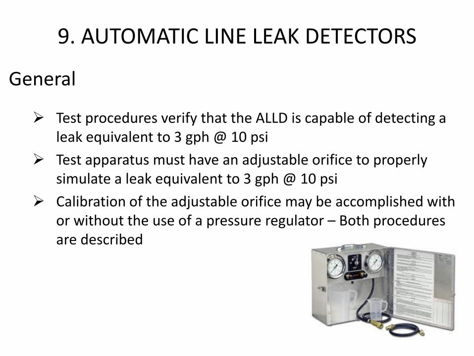
Test procedures verify that the ALLD is capable of detecting a leak equivalent to 3 gph @ 10 psi
Test apparatus must have an adjustable orifice to properly simulate a leak equivalent to 3 gph @ 10 psi
Calibration of the adjustable orifice may be accomplished with or without the use of a pressure regulator – Both procedures are described
9. AUTOMATIC LINE LEAK DETECTORS

General
Test must confirm that the STP properly cycles on/off (verifies STP relays are functioning)
Simulated leak must occur at the dispenser that is at the highest elevation above the STP
If piping system has master/satellite configuration, simulated leak must occur at the farthest satellite dispenser
9. AUTOMATIC LINE LEAK DETECTORS

9.1 Mechanical Leak Detectors
Visual inspection
Verify leak detector “trips” when line pressure nears zero
Verify leak detector sees a simulated leak equivalent to 3 gph @ 10 psi
• “Slow flow” condition exists
9. AUTOMATIC LINE LEAK DETECTORS

9.2 Electronic Line Leak Detectors
Visual inspection
Verify system setup parameters are correct
Verify leak detector searches for leak
Verify leak detector sees simulated leak equivalent to 3 gph @ 10 psi
• Causes alarm condition
• Causes STP shutdown if required by AHJ
9. AUTOMATIC LINE LEAK DETECTORS

1. Introduction
2. Definitions
3. Safety
4. Tank Secondary Containment Integrity Testing
5. Piping Secondary Containment Integrity Testing
6. Spill Bucket and Containment Sump Testing
7. UST Overfill Equipment Verification, Inspection and Testing
8. Electronic Monitoring System Inspection and Testing
9. Automatic Line Leak Detectors
10. Shear Valve Inspection and Testing
11. Emergency Stop
12. Documentation
Appendices
PEI/RP1200-12 ------------------------------------------------------

Two types of shear valves
10. SHEAR VALVE INSPECTION & TESTING
Product Shear Valve Vapor Shear Valve

10.2 Product Shear Valves
Visual inspection
Verify anchored securely and at correct height
Confirm trip mechanism is functional
Manually close the valve poppet
Verify that no product flow occurs
10. SHEAR VALVE INSPECTION & TESTING

10.3 Vapor Shear Valves
Visual inspection
Verify anchored securely and at correct height
10. SHEAR VALVE INSPECTION & TESTING

1. Introduction
2. Definitions
3. Safety
4. Tank Secondary Containment Integrity Testing
5. Piping Secondary Containment Integrity Testing
6. Spill Bucket and Containment Sump Testing
7. UST Overfill Equipment Verification, Inspection and Testing
8. Electronic Monitoring System Inspection and Testing
9. Automatic Line Leak Detectors
10. Shear Valve Inspection and Testing
11. Emergency Stop Switches
12. Documentation
Appendices
PEI/RP1200-12 ------------------------------------------------------

General
May be more than one e-stop switch at the facility
Must test every e-stop switch individually
Verify e-stop is clearly labeled
Verify easily accessible
11. EMERGENCY STOPS

Manually activate switch to confirm power has been disconnected to:
• All dispensers
• All STPs
• All power, control and signal circuits associated with dispensers and STPs
• All other non-intrinsically safe electrical equipment in the classified areas of the UST system and dispensers
11. EMERGENCY STOPS

1. Introduction
2. Definitions
3. Safety
4. Tank Secondary Containment Integrity Testing
5. Piping Secondary Containment Integrity Testing
6. Spill Bucket and Containment Sump Testing
7. UST Overfill Equipment Verification, Inspection and Testing
8. Electronic Monitoring System Inspection and Testing
9. Automatic Line Leak Detectors
10. Shear Valve Inspection and Testing
11. Emergency Stop
12. Documentation
Appendices
PEI/RP1200-12 ------------------------------------------------------

Sample forms are provided for every test
Proper documentation of testing is essential
12. DOCUMENTATION

1. Introduction
2. Definitions
3. Safety
4. Tank Secondary Containment Integrity Testing
5. Piping Secondary Containment Integrity Testing
6. Spill Bucket and Containment Sump Testing
7. UST Overfill Equipment Verification, Inspection and Testing
8. Electronic Monitoring System Inspection and Testing
9. Automatic Line Leak Detectors
10. Shear Valve Inspection and Testing
11. Emergency Stop
12. Documentation
Appendices
PEI/RP1200-12 ------------------------------------------------------

Appendix A-1 & A-2
• Fiberglass tank manufacturers’ precision tank tightness testing procedure for brine filled double-walled tanks
APPENDIX A – FRP Tank Manufacturer’s Test Checklists/Data Logs

Convert Units for Measuring Pressure
PSIG - Inches HG – Mbar – Bar
Convert Units for Measuring Vacuum
Inches H2O – Inches HG – PSIG – Mbar - Bar
APPENDIX B – Pressure & Vacuum Conversion Tables

C-1 Tank Secondary Containment Integrity Testing Dry Test Method
C-2 Piping Secondary Containment Integrity Testing
C-3 Spill Bucket Integrity Testing Hydrostatic Test Method Single and Double-Walled Vacuum Method
C-4 Containment Sump Integrity Testing Hydrostatic Testing Method
C-5 UST Overfill Equipment Inspection Automatic Shutoff Device and Ball Float Valve
C-6 Overfill Alarm Operation Inspection
C-7 Automatic Tank Gauge Operation Inspection
C-8 Liquid Sensor Functionality Testing
C-9 Mechanical and Electronic Line Leak Detectors Performance Test
C-10 Shear Valve Operation Inspection
C-11 Emergency Stop Switch Operation Inspection
APPENDIX C – SAMPLE TEST DATA SHEETS

API
FT&PI
ICC
NFPA
PEI
STI
UL
OSHA
EPA
APPENDIX D – PUBLICATION REFERENCE

Doing what we can to protect service stations
PEI RP/1200