Lorenzo Electronics - LE1200 Self test
20
Lorenzo Electronics LE1200 Integrated Digital In-Circuit Tester (ICT) & Boundary Scan Tester (BST) Self Test
-
Upload
mark-chien -
Category
Engineering
-
view
9 -
download
2
Transcript of Lorenzo Electronics - LE1200 Self test

Lorenzo Electronics
LE1200
Integrated
Digital In-Circuit Tester (ICT)
&
Boundary Scan Tester (BST)
Self Test

Scope (1)
● Demonstrates LE1200 Digital ICT + BST tester running tests over portions of Digital ICT tester System board.
● Test capability to detect Device Under Test (DUT) pin-short faults.
● Test patterns to detect pin-open faults between Boundary Scan (BSC) IC pins and other DUT circuit nodes.
● Interactive, efficient, and system-wide parallel Digital ICT & BST tester operations.

Scope (2)
● Excellent BST controllability and observability.● Detailed logging files containing logic states of
the digital ICT tester pins and the BSC IC cells.● Fault insertion test demonstrating fault isolation
capabilities.
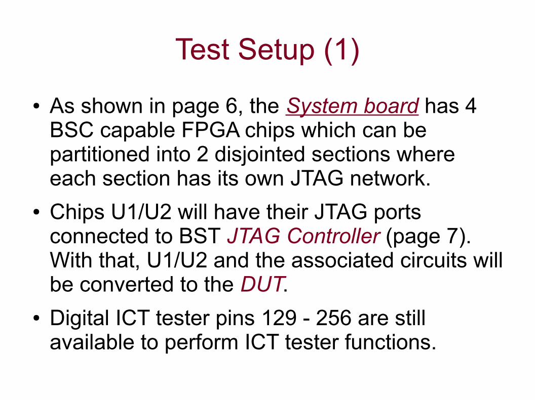
Test Setup (1)
● As shown in page 6, the System board has 4 BSC capable FPGA chips which can be partitioned into 2 disjointed sections where each section has its own JTAG network.
● Chips U1/U2 will have their JTAG ports connected to BST JTAG Controller (page 7). With that, U1/U2 and the associated circuits will be converted to the DUT.
● Digital ICT tester pins 129 - 256 are still available to perform ICT tester functions.

Test Setup (2)
● In Test Interface Board (P.7), 8 jumper wires are connecting the “converted” DUT to the Digital ICT tester pins 129 – 136.
● DUT equivalent circuit, labeled with ICT tester pin names defined in ICT tester configuration and FPGA pin's port names defined in its BSDL file, is depicted on Page 8.
● With Buffer chip's directional control properly taken care of, the selected U2 ports and ICT tester pins logic states can mirror each other.

DUT ICT Tester
U1/U2 JTAG port
U1 U2 U3 U4
System Board

Jumper wires interconnecting ICT tester pins 121-128 and 129-136
JTAG Controllerconnected to U1/U2 JTAG port
Test Interface Board: Connections

BSC ports ICTDUT
DUT Equivalent Circuit

Running Self Test
● This LE1200 Self test involves both BST and Digital ICT testers. Each tester executes test commands from PC via separate USB link. With that, test patterns - sets of I/O data, will be exchanged between DUT and the testers.
● Tests will be executed with or without the fault inserted. Excerpts of test trace files for both types of tests will be depicted. The resultant test patterns will be highlighted to illustrate LE1200 fault detection capability.

Test Patterns (1)
● Each test is divided into 2 groups. The 1st group, test pattern 1-23, FPGA device U2 BSC output cells will drive the circuits while their input cells and digital ICT pins129-136 will be on the receiving end .
● 2nd test group, test pattern 24-42, digital ICT pins129-136 will drive the circuits and U2 BSC input cells will be the receivers. In the mean time, U2 BSC output cells are set to Hi-Z states.

Test Patterns (2)
● In test pattern 1, U2 pins output cells are initialized with a walking-1 bit streams. The expected input cells logic states are set to 'X'.
● In the follow on tests patterns with alternating ICT/BST test operations, ICT will validate the received logic states against the preceding BST test patterns of walking-1 bit stream.
● A BST test pattern for U2 input cells will be validated against the associated output cells logic states in the preceding BST test pattern.

Test Patterns (3)
● ICT driving tests will start with test pattern #24 which initializes U2 input cells to 'X' state and output cells to Hi-Z states.
● Test pattern #25 will setup ICT to drive the walking-1 bit streams.
● In the follow on test patterns with alternating BST-ICT test operations, BST will validate U2 input cells data against the preceding ICT driving data of walking-1 bit stream.
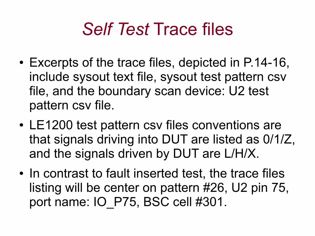
Self Test Trace files
● Excerpts of the trace files, depicted in P.14-16, include sysout text file, sysout test pattern csv file, and the boundary scan device: U2 test pattern csv file.
● LE1200 test pattern csv files conventions are that signals driving into DUT are listed as 0/1/Z, and the signals driven by DUT are L/H/X.
● In contrast to fault inserted test, the trace files listing will be center on pattern #26, U2 pin 75, port name: IO_P75, BSC cell #301.

Sysout – CSV file

Sysout – BST pattern #26

BSC device (U2) CSV file

Self Test Trace files - fault inserted
● Ground wire will be connected to ICT pin #36 and repeat the previous test. The excerpts of trace files are depicted on P.18-20.
● Sysout csv file displays ICT failed in detecting logic 0 from DUT – pin name: d136.
● Sysout text file indicates that tdo bit stream's bit #301 is 0 @ test pattern #26.
● BSC device: U2 csv file displays that its port: IO_P75 failed BST in detecting logic 0 from DUT.

Sysout (failed) – test patterns

Sysout (failed) – BST pattern #26

BSC device (U2-failed) test patterns