
Loran/GPS Interoperability Interoperability 1991.pdf · MTBM MVUE NAD-27, 83 NASA NATO NBS NDB NDS...
179
Wild Goose Association Tutorial '91: Loran/GPS Interoperability Ft. Magruder Inn Willi::unsburg, Virginia Septmeber 30, 1991 Navtech Serr1inarsr lnc. 2775 S. Quincy St .. Suite 610 • Arlington. VA 22206-2204 • USA Tel. (703) 931-0500 •FA)( (703) 931-0503
Transcript of Loran/GPS Interoperability Interoperability 1991.pdf · MTBM MVUE NAD-27, 83 NASA NATO NBS NDB NDS...
Wild Goose Association
Tutorial '91:
Loran/GPS Interoperability
Ft. Magruder Inn Willi::unsburg, Virginia
Septmeber 30, 1991
Navtech -~ Serr1inarsr lnc.
2775 S. Quincy St .. Suite 610 • Arlington. VA 22206-2204 • USA Tel. (703) 931-0500 •FA)( (703) 931-0503

B'~I Navtech 1~~! Seminars,1nc.
0830
0945
1100
1200 13~8
1430
1545
1700
Loran-C/GPS Interoperability
Dr. Gerard Lachapelle University of Calgary
Fundamentals of GPS I Course introduction; propagation at 1.5 GHz GPS Concepts; description of system segments Constellation design; schedule; SPS and PPS Absolute and differential accuracy performance
Fundamentals of GPS If Signal components, broadcast message; effect of SA &
A-S; receiver characteristics and classification Real-time differential operation; availability and integrity Impact of GLONASS and INMARSAT's overlay
Fundamentals of Loran-C Propagation at 100 kHz; hyperbolic & rho-rho positioning Signal structure; pulse distortion Effects of refractivity, conductivity and atmospheric noise Equipment characteristics; North American coverage
Lunch
Calibration of Loran-C with GPS Seasonal and permanent Loran-C grid distortions Mixed path, topographic and altitude effects Use of differential GPS to calibrate Loran-C Applications to land, marine and air cases Calibrated Loran-C performance
Concepts of Loran-C/GPS Interoperability Description of approaches to interoperability Accross chain and GPS-Loran-C time Synchronization aspects; multi-chain versus single
operations Hybrid receiver characteristics and clasification
Applications of Loran-C/GPS Interoperability Minimum standards for sole-means radionavigation Loran-C/GPS coverage and availability in USA Integrity issues; fault detection and isolation Loran-C/GPS for RNAV; test results and prospects
2775 S. Quincy St. •Suite 610 •Arlington. VA 22206-2204 • USA • (703 l 931-0500 • FAX (703) 931-0503


• AIC ACU ADF ADI AEEC AFB AFGL AFSCF AGD AGL ARINC ARTCC ASAT ATE BPS CIA CDMA CDU Ce CEP Comm. CO NUS CNS CRPA csoc D to A DARPA DL 2DRMS DGPS DMA DME DOC DOD DOP DOT DSARC DT&E ED EIRP ECEF EMC EMI EMP
Acronyms and Abbreviations of Navigation Technical Terms
Aircraft Antenna Control Unit Automatic Direction Finder Attitude Direction Indicator Airlines Electronic Engineering Committee Air Force Base Air Force Geophysics Lab (was AFCRL) (Hanscom AFB) Air Force Satellite Control Facility Australian Geodetic Datum Above Ground Level Aeronautical Radio, Inc. (establishes avionics standards) Air Route Traffic Control Center (FAA facility) Anti-satellite Automatic Test Equipment Bits per second Coarse/Aquisition GPS signal; available to civil users; also called SPS Code Division Multiple Access Control Display Unit Cesium (-Beam Atomic Standard Clock) Circular Error Probable Communications Continental United States Communications, Navigation and Surveillance Controlled Radiation (Reception) Patterned Antenna Consolidated Space Operations Center (at Falcon AFB) Digital to Analog Defense Advanced Research Projects Agency (Washington, DC) Data Link 2 times the standard deviation (root mean square); 2 dimensional case Differential GPS Defense Mapping Agency Distance Measuring Equipment Department of Commerce Department of Defense Dilution of Precision Department of Transportation Defense Systems Aquisition Review Council Development, Test and Evaluation European Datum Effective Instantaneous Radiated Power Earth-Centered, Earth-Fixed Electromagnetic compatibility f:lectromagnetic interference Electomagnetic pulse
EOL EW FAA FANS FCC FCC FDMA FOC FOM FMI FRPA FRP FY GPS GDM GDOP GMT HD HDOP HDUE HOL HOW HSI HUD ICAO ICD-GPS IFRB IOC ILS IMU IMO INS ION IONDS IOT&E IR ITU JCS JPO J/S LI L2 L-band LD
End of Life Electronic Warfare Federal Aviation Adminstration (part of DOT) Future Air Navigation Systems Committee Federal Communications Commission Fire Control Computer (JPO version) Frcquecy Division Multiple Access Full Operational Capabiltiy Figure of Merit (sometimes called FM) Flexible Modular Interface Fixed Radiation Pauern Antenna Federal Radionavigation Plan Fiscal Year Global Positioning System General Development Model Geometric Dilution of Precision Greenwhich Mean Time High Dynamic Horizontal Dilution of Precision High Dynamic User Equipment High Order Language (for computer programming) Hand-Over Word Horizontal Situation Indicator Head-up display International Civil Aviation Organization Interface Control Documant (issued by JPO) International Frequency Review Board Initial Operational Capability Instrument Landing System Inertial Measurement Unit International Maritime Organization Inertial Navigation System Institute of Navigation Integrated Operational Nuclear Detection System Initial Operational Test and Evaluation Infra-red International Telecommunications Union Joint Chiefs of Staff Joint Program Office J;unming/Signal Ratio GPS L-band signal 1 (1575.42 MHz) GPS L-band signal 2 (1227.6 MHz) L-band frequency (about 1-2 GHz) Low Dynamic

LEP LOP LRU LORAN MARAD MCS MD M mean CT M max CT MLV MLS MMD MP MPS MSL MSS MTBF MTBM MVUE NAD-27, 83 NASA NATO NBS NDB NDS NHTSA NSA nsec NTDS nm NUDET OdHI ocs OMB OSD P-code P-channel PDOP PL PLL PN PPS PRN PSK RAJ PO Rb RF RDSS RMS RNAV
Linear Error Probability (50 percent) Line of Position Line Replaceable Unit Long Range Navigation System Maritime Administration Master Control Station (for GPS) (at Colorado Springs) Medium Dynamic Maintenance Mean Corrective Time Maintenance Maximum Corrective Time Medium Launch Vehicle (e.g. Delta II) Microwave Landing System Mean Mission Duration Manpack Meters per second Mean Sea Level Mobile Satellite Service Mean Time Between Failures Mean Time Between Maintenance ManN ehicular User Equipment North American Datum (1927, 1983) National Aeronautics and Space Administration North Atlantic Treaty Organization National Bureau of Standards 9now the Nat'! Inst. of Standards & Tech.) Non-directional Beacon Navigation Development Satellite National Highway Traffic Safety Administration National Security Administration nanosecond Naval Tactical Data System nautical miles Nuclear Detection 0 decibels (unity gain) - the radiation pattern ain of an isotropic antenna Operational Control Segment Office of Management and Budget Office of the Secretary of Defense Precision code - provided for military GPS users & selected others Precision code channel Position Dilution of Precision (x,y,z) Pseudolite Phase Lock Loop Pseudo Noise Prcise Positioning Service Pseudo Random Noise Phase Shift Key Range Applications Joint Program Office Rubidium (gas atomic standard clock) Radio Frequency Radiodetermination Satellite Service Root Megan Square Area Navigation
RNPC Required Navigation Perfom1ance Capability RPU Receiver Processing Unit RPV Remotely Piloted Vehicle RSPA Research and Special Programs Administration of OOT RSS Root Sum Square RTCA Radio Technical Commission for Aeronautics RTCM Radio technical Commission for Maritime Services S-band Microwave frequency band, about 2-4 GHz SA Selective Availability SAC Strategic Air command SIC Space Craft SC-155 RTCA Special Committee on future CNS for navigation SC-159 RTCA Special Cornn1ittee to set operational performance standards forGPS SCF Satellite Control Facility SEP Spherical Error Probability (50 percent) sigma Standard deviation SGLS Space-Ground Link, S-band SPS Standard Positioning Service (for GPS) STOL Short Take-Off and Landing STS Space Transportation System SUNS Small Unit Navigation System SV Space Vehicle TAC Tactical Air Command TACAN Tactical Air Navigigation System TBD To Be Determined TD Tokyo Datum TDOP Time Dilution of Precision (l) TDMA Time Division Multiple Access TDRSS Tracking and Data Relay Satellite System TT&C Tracking, Telemetry and Control TTFF Time To First Fix TTSF Time To Subsequent Fix UE User Equipment UERE User Equivalent Range Error UMTA Urban Mass Transit Administration URE User Range Error USNO U.S. Naval Observatory UTC Universal Time Coordinated VAFH Vandenburg Air Force Base VDOP Vertical Dilution of Precision (z) VHF Very High Frequency VLBI Very Long Baseline Interferometry VLF Very Low Frequency VOR VHF Omni-Range navigation system VPA Vehicle Power Adapter W ARC World Administrative Radio Conference WDOP Weighted Dilution of Precision WGS-72, 84 World Geodetic System (1972 and 1984) w.r.t. YPG
with respect lo
Yuma Proving Cround 11 Prcpurcd by Navtcch Su11.in.ar1, Irie.
2775 S. QMin.cy Strccl, Suilc 6/0 Ar/i,,,gt°""· VA. 22206·22JJ..I (103) 931.-0500 ·FAX (703) 931·0503

GPS & GLONASS. Information Sources
Civil GPS Service GPS Information Center
The Civil GPS Service was established to provide civil GPS users with information on system starus and a point of contact As a pan of this Service, the U.S. Coast Guard has begun operations of the GPSIC on a "test and evaluation" basis. Current services include GPS Operational Advisory Broadcasts containing current constellation starus. future scheduled outages, and an almanac suitable for making GPS coverage and satellite visibility predictions. The OAB 's are available 24 hours a day by computer bulletin board, or as a recorded telephone message at (703) 866-3826 (without almanac). The com ms parameters for the bulletin board are: 8 data birs, 1 stop bit, no parity. For modem speeds of 300, 1200 or 2400 bps call (703) 866-3890 4800 or %00 bps call (703) 8fi6-3894 (For FTS subscribers. the numbers are 398-3890 and 398-3894.) For live information, call (703) 8fi6-3806 or fax (703) 8fi6-3825.
GPS Satellite Clock Behavior and Related GPS Information
U.S. Naval Observatory Washington, DC 20392-5100 USA
Available telephone lines: (202) 653-0068, 0155, 1079 Baud rates: 1200, 2400 or 9600 Comm. parameters: 8 data bits, 1 stop, no parity
terminate lines with CR/LF Password: CESIUM133 Internet access: Telnet to tycho.usno.navy.mil (192.5.41.239).
Login as ads. Comments to: [email protected]
USNO Series 4 Weelcly Bulletins: Received by mail, they contain information on lhe starus of GPS and timing data. Contact Francine Vannicola at (202) 653-1525 for further assistance.
Performance of GPS Satellite Survey Systems To request information, contact:
GPS Test Coordinator, Instrument Subcommittee Federal Geodetic Control Committee, NGS, NOAA N/CG14, Rockwall 320 Rockville, MD 20852 USA (301) 443-8171
GPS World Magazine The first magazine devoted entirely to GPS, this is an excellent bimonthly source of information on ongoing system developments, policy and ;i.pplications. For a free subscription, contact:
CPS World 859 Willamette Street, PO Box 10955 Eugene, OR 97440-2460 USA Telephone: (503) 343-1200
GPS Bulletin Board at Holloman Formerly located at Yuma. this bulletin board has recently been moved to Holloman Air Force Base. The bulletin board provides a daily almanac, observed range errors, comments on the satellites. and the OCS Advisories. Requires full duplex, 8-bitdata words, no parity and one stop bit (preferred because it supports the X-modem and Y-modem error checld.ng block transmission) m: full duplex, 7-bit word, odd or even parity and one stop biL 1200 (preferred) or 300 baud (505) 679-1525 Live system operator (505) 679-1784
GPS Bulletin Board Global Satellite Software, Inc. 5339 Prospect Road, Suite 239
San Jose, CA 95129 A source of daily almanacs by modem available free to the public. Telephone: (408) 252-7358 Baud rate: 1200 or 2400 System Operator: Glen Sieben (408) 252-7490 (voice)
GLONASS Bulletin Board 3S Navigation
23141 Plaza Pointe Drive Laguna Hills, CA 92653 USA
Telephone: (714) 830-3794 Baud rate: 1200 or 2400 Protocol: 8 data bits, 1 stop bit. no parity Contact Jim Danaher at (714) 830-3777 for funher assistance.
Precise GPS Orbit Information Government: Precise orbital positions and velocities based on post computations of tracking data collected from stations of the Cooperative International GPS Tracking Network (CIGNET) are available from NGS. Satellite orbital data are scheduled to be available two weeks after the tracking data are collected. For a description of fonnats, fee schedule or to order data. contact:
National Geodetic Infonnation Center, N/CG 17 National Geodetic Survey, NOS, NOAA Rockville, MD 20852 USA (301) 443-8631
Commercial: Precise orbit data is available from the Western Geophysical Division, Western Atlas International, using data obtained from its tracking network stations. For a description of format, fee schedule, or to order data, contact:
Jim Cain, Manager, GPS Services Western Geophysical Division, Western Atlas Int'l 3600 Briarpark Drive Houston, TX 77042-4299 USA (713) 964-6345


Navtech Book & Software Store List of publications available as of September 30, 1991 • A Division of Navigation Technology Seminars, Inc.
41 :l,Z·Vf f l,[1 l#?iliil 11QQf 9 Assessment of Emerging Technologies tor Future Navigation Systems in the Canadian Transportation Sector, E.J. Krakiwsky, G. Lachapelle and K.P. Schwarz, University of Calgary, 1990, $40.00. Review of Canadian multimodal navigation requirements and analysis of status of RF hardware and mobile communication systems. 248 pages, softback.
Avionics Navigation Systems, Kayton and Fried, John Wiley & Sons, 1969, $110.00. A respected text in the field. 666 pages, hardback.
Digital Communications by Satellite, Dr. James J. Spilker, Jr., Prentice Hall, 1977, $73.00. An excellent treatment of the topic, and a fine exposition of pseudonoise (PN) code processing, by one of the originators of the GPS signal structure. 672 pages, hardback.
Dutton's Navigation and Piioting, 14th edition, Elbert S. Maloney, U.S. Naval Institute, 1985, $44.95. Outstanding introductory level volume covering all facets of marine navigation. Also a valued item for professional gift giving. 91 O pages, hardback.
Federal Radlonavigatlon Plan 1990, Do DI Do T, $15.00. System descriptions, current status and future phase-in/phase-out plans for navigation systems. This is the latest version. About 120 pages, softback. Prior years' FRPs on sale for $7.50.
Geodesy for the Layman, Lt. Col. Richard K. Burkard, et. al., NOAA, 1983 $4.50. An excellent summary of the fundamentals of geodesy with discussion of ellipsoids, the geoid, horizontal surveying, leveling, geodetic datums and gravity. 96 pages, softback.
Geodetic Glossary, National Geodetic Survey, 1986, $20.00. The official U.S. government glossary of geodetic and survey terms, with over 5,000 definitions. A highly useful resource. 274 pages, softback.
Global Navigation, A GPS User's Gulde, Neil Ackroyd & Robert Lorimer, Lloyd's of London Press, 1990, $80.00. Practical info on the marine applications and implications of GPS. Coastal navigation and safety at sea are covered. 202 pages, hardback.
'fobal Positioning System, Volumes /-Ill. The Institute of Navigation, $50.00. Highly recommended as a GPS reference. Also available Jividually: Volume I (1980) = $15 (246 pages), Volume II (1984) .. $15 (257 pages), Volume Ill (1986) .. $20 (293 pages), softback.
GPS: A Gulde to the Next Utility, published by Trimble Navigation, Ltd, 1988, $8.95. A simple overview of GPS. 76 pages, softback.
GPS Receiver Survey with basic equipment specifications and copies of equipment photos, published by Navtach Seminars, $25.00. A comprehensive, detailed, and continuously-updated listing of GPS receivers, their characteristics and performance. 78 pages.
GPS Satellite Surveying, Alfred Leick, Ph.D., John Wiley & Sons, 1990, $64.50. New book which gives comprehensive coverage of theoretical aspects (including derivations), as well as practical background information on the subject. 352 pages, hardback.
Gulde to GPS Positioning, David Wells, Ph.D., editor, Canadian GPS Associates, 1986, $35.00. Excellent, readable book for surveyors, geodesists and others using GPS for precise positioning. Format is half diagrams and drawings, half text. -600 pages, softback.
Integrated Aircraft Navigation, James L. Farrell, Ph.D., Academic Press, 1976, $75.00. A respected, comprehensive development of navigation systems integration principles and techniques. 350 pages, hardback.
Introduction to Random Signals and Applied Kalman Rlterlng, 2nd ed., R. Grover Brown, Ph.D., and Patrick Y. C. Hwang, John Wiley & Sons, 1991, $62.95. Excellent text on applied Kalman filtering with a focus on navigation system applications; Includes Kalman filter PC software. 499 pages, hardback.
Marine Navigation 3, Third Edition, Richard R. Hobbs, Naval Institute Press, 1990, $38.95. Originally published in two volumes, has now been combined into one. Much of book based on American Practical Navigator and Dutton's Navigation and Piloting, hardback.
NGS State Plane Coordinate Manual NAO '83, NOAA, 1988, $10.00. A necessity for those dealing with state plane coordinates, especially coordinates related to the National Geodetic Reference System as a data base. 119 pages, softback.
North American Datum of 1983, NOAA Professional Paper NOS 2, Charles R. Schwarz (Ed.), NGS, 1990, $13.00. A detailed description of the datum including history, assessment, methodology, execution/results, and implementation. 256 pages, softback.
dlonavigatlon Systems, Borja Forssell, Prentice Hall International, 1991, $36.00. A comprehensive review of radionavigation systems .. A marine applications. 392 pages, hardcover.
Satellitengeodasle; Grundlagen, Methoden und Anwendungen, Gunter Seeber, Ph.D., de Gruyter, 1989, $123.75. (Limited number available - overseas orders will take 8 weeks.) (Expected to be published in English in 1992.) 489 seiten, hardback.

Signal Processing- The Modern Approach, James V. Candy, McGraw-Hill, 1988, $58.25. A highly useful reference. 386 pages, hardback.
The Quantum Physics of Atomic Frequency Standards, Vanier & Audain, 2 volumes, 1989, £250. An extensive treatment of the subiect covering both theoretical and experimental aspects together with applications. An invaluable reference. Hardback.
Software (Complete descriptions available upon request.)
From Geodetic Research Services Ltd.:
Product Descrjotjon Sjnqle Copy Price ljn US$) MacSat 3.0** Spade 4.2* MacGepsal 3.0**
CndGeold 1.3***
DIPOP 2.1***
NETVAL 1.0***
GeoLab™*
A general purpose satellite tracking & visibility program Solar and Polaris Azimuth DEtermination pkg. for land surveyors Mac GEneral Purpose SAtellite Alert pkg.
Optimizes survey time under existing limited GPS coverage Canadian & Northern U.S. Geoid program for GPS.
Determines orthometric heights. Differential POsitioning Program: Estimates precise relative
station coordinates from carrier phase observations GPS network evaluation software tor validation and
densiiication surveys Geodetic network adjustment software with graphics GPS Environment for Geolab™ Both Geolab™ and GPS Environment
$50 $50, $100 with Source Code $100
$100
$500, $1000 with Source Code
$1800
$2555 $444 $2999
(Significant educational discounts available for above programs. please contact Navtech Info Service for more information.)
From Trimble Navigation Ltd.: Product Descriotjon Single cooy orjce 24-month uoqrades SATVIZ* Satellite visibility and geometry analysis software $149.50 NIA GPSLAB* GPS instrumentation and data recording software $250 NIA POST-NAV* Differential GPS navigation post-processing software $4, 750 $950 D.NAV Reference• Differential GPS reference software $10,000" $2,500 D.NAV Navigator• Differential GPS navigation software $3,500 $850
"Price includes: System software and one day of initial system training at Trimble's Sunnyvale, California facility. Price does not include: GPS receivers, data link, personal computers/peripherals, or system installation and assembly. System installation and assembly quoted upon request.
From Global Satellite Software (GSS): Product Description SPS* Basic satellite prediction software SMS* Professional satellite monitoring software
• includes modem software; supports 250 printers; works tor all GPS receivers, and accepts NASA
Single Copy Prjce $195 $495
and NORAD 2-line element sets; advanced analysis
From The MathWorks: Product MATLAB™
386-MA TLAB™ 386/Weitek-MATLAB™ Signal Processing Toolbox Control System Toolbox System ID Toolbox Optimization Toolbox SIMULAB™
Description High productivity software for advanced
engineering analysis Designed to take advantage of 386 capabilities
Filter design, spectrum analysis, 1-D & 2-D, etc. Models, SVD frequency response plots, etc. Modelling, spectral analysis, validation, etc. Programming, minimax & semi-infinite probs, etc. Simulation, linearization, optimization, etc.
MS-QOS Price $695
$1595 $1995 $295 $695 $495 $495
Contact Navtech for information on more available toolboxes.
Macintosh Price $795
$295 $695 $495 $495 $3995
Navtech is a North American dealer for Math Works. If you are outside this region and are interested in obtaining information or copies of MathWorks software, please contact your local dealer.
*IBM or compatible PC software only ••Macintosh software only
···1BM/PC QL Macintosh software available (please indicate choice when ordering)
NOTE: Support tor all of your software purchases will be provided by the software manufacturers.

GPS Civil Market Study GPS Civil Markets in the 1990's, Victor H. Prushan, Keith D. McDonald, Colin M. D. Beatty and Carolyn P. McDonald. Com
ted in August 1991, this study includes an analysis of major GPS markets, applications, and the current business environment; .• ajor technology and system issues; an analysis of competition and competing systems; projections of market growth; and an
examination of the available business opportunities. $8,995 post publication price includes individual consultation.
Meeting Proceedings (Tables of Contents for individual proceedings available free of charge, upon request.)
Proceedings of the First International Symposium on Precise Positioning with GPS, NOAA. Rockville, MD, May 1985 $50.
Proceedings from the 1st, 2nd and 4th International Geodetic Symposiums held in Las Cruces, NM, and Austin, TX. $50.00 each. 3rd International Geodetic Symposium held in Las Cruces, NM $35.00 5th International Geodetic Symposium $75.00
Proceedings for all IEEE PLANS meetings available upon request
All Institute of Navigation proceedings, including the Satellite Division ION GPS meetings, since 1984. ($50.00 each unless otherwise noted.) Satellite Division's International Technical Meeting, ION GPS-90, September 1990, Colorado Springs, CO
National Technical Meeting, January 1990, San Diego, CA Satellite Division's 2nd International Technical Meeting, ION GPS-89, September 1989, Colorado Springs, CO ($70.00) 45th Annual Meeting, June 1989, Old Town Alexandria, VA National Technical Meeting, January 1989, San Mateo, CA Satellite Division's International Technical Meeting, ION GPS-88, September 1988, Colorado Springs, CO ($70.00) Satellite Division Student Paper Competition Proceedings, September 1988, Colorado Springs, CO ($10.00) 44th Annual Meeting, June 1988, Annapolis, MD National Technical Meeting, January 1988, Santa Barbara, CA Satellite Division 1st Technical Meeting, September 1987, Colorado Springs, CO 43rd Annual Meeting, June 1987, Dayton, OH National Technical Meeting, January 1987, Anaheim, CA 42nd Annual Meeting, June 1986, Seattle, WA National Technical Meeting, January 1986, Long Beach, CA 41 st Annual Meeting, June 1985, Annapolis, MD National Technical Meeting, January 1985, San Diego, CA 40th Annual Meeting, June 1984, Cambridge, MA National Technical Meeting, January 1984, San Diego, CA
(Note: Some proceedings are out of print and will be sold as duplicated copies. More recent meetings' proceedings can also be obtained upon request.)
Royal Institute of Navigation Proceedings: (example of UK to US shipping) RIN 85 Navigation Equipment and Training Standards $30.00 + Post: Air $20.00, Surface $6.00 RIN 85 Land Navigation and Location for Mobile Applications $60.00 + Post: Air $28.00, Surface $8.00 RIN 87 Data Dissemination and Display Electronics in Navigation $60.00 +Post: Air $34.00, Surface $10.00 RIN 88 Radionav 2000 $75.00 +Post: Air $28.00, Surface $10.00 RIN 89 Orientation and Navigation for Birds, Humans and Other Animals $75.00 + Post: Air $26.00, Surface $8.00
Special Orders will be gladly accepted without extra fees! ALL PRICES SUBJECT TO CHANGE WITHOUT NOTICE!
0 Please add me to the Navtech Book and Software Store mailing list (Complete this even if you are already on our mailing list for Navtech Seminars):
Name: Organization: ___________________ _
Address : Street------------------- Internal Mail Code City __________ State/Prov. _____ Postal or Zip Code ____ _ Country _______ _
Also, please send me: Foreign customers, please specify:_ air, or _surface shipping
_ List of the table of contents for survey and GPS related meeting proceedings _ Description of software packages _ Copy of circled books My telephone number is: ( FAX:-----------
Note: Books will be charged at the publishers' retail prices, plus $5.00 handling fee per purchase order of any size, plus sales tax (if applicable) and shipping costs. We are happy to send books on approval, however, customers must pay for their postage. Checks drawn on
US benks, purchase orders, and Visa, MasterCard and Diners Club cards are accepted. We request foreign customers to pay by credit card, If possible.
Card# Exp. date ---Signatur.,_ ________________ _
Please make checks payable, and return this form to: Navtech Information Service, 2775 S. Quincy St. #610, Arlington, VA 22206-2204 USA
or call (703) 931-0500, or FAX (703) 931-0503 For more information, ask for Franck Boynton or Susie Jones


Navtech Seminars, inc.
Loran-C/GPS Interoperability
for presentation at the Fort Magruder Inn
Williamsburg, Virginia
September 30, 1991
The sessions will begin at 0830 and finish at 1700. Each session will last one hour,withfifteen minute breaks in between.
There will be a break/or lunchfrom 1200 to 1315.
Instructor:
Prof. Gerard Lachapelle Department of Surveying Engineering
University of Calgary 2500 University Drive, NW
Calgary, Alberta T2N 1N4 CANADA (403) 220-7104
( 403) 284-1980 (fax)
2775 S. Quincy St. •Suite 610 •Arlington.VA 22206-2204 • USA• (703) 931-0500 • FAX (703) 931-0503

(

FUNDAMIEN1r AJL§ OF GIP§ K
CO \URSIE liN'IrR OID \U C1fKON ANID NO'Ir A 'IrKON
GJP§ CONCIEJP1f§
• Major Characteristics
• Signal Structure
• Broadcast message
• System Segments
• Satellite Series
SYS1fIEM JPIERFORMANCIE
• Accuracy measures and Dilution of Precision
• Selective Availability
• SPS and PPS Single Point performance (S.A. Off/On)
• Differential GPS concept and performance
• Ground tracks
GPS ANID 01fHIER SYS1fIEMS
• GLONASS
• Inmarsat's Geostationary Overlay
GJP§ liNFORMA 1f1[0N SO\URCIE§ G. Lachapelle (1991)


R = (X,Y,Z) T r - (x,y,z) T
NOTATION
Position of receiver ,. "p(U)~~-- 1 ;Au:- 1,..,.~) ,, -r:::
position of satellite ·""~A)
P =II r - Rll distance between satellite and receiver -trve.,/Jt//"'#1~
c f "A=c/f
vacuum speed of light carrier frequency carrier wavelength
cp carrier phase observation (in cycles) , ffi 'i th it ra le! 0 11-4Y'-'-¥ = - "'- 't' carrier phase observation (in length units) :;J .a( c1cle~
d-t time delay observation p ~ c d 't pseudo-range observation (in length units)
',_ \' . . . ' ~
''," d p, ·· : '.\'· ·· · « • range error due to inaccurate ephemerides
dt satellite clock error dT receiver clock error
d ion range error due to ionospheric refraction
d trop · .. « -"' range error due to tropospheric refraction N •. · " · · ,, · integer carrier phase ambiguity
<P = p + c(dt - dT) +"AN - <lion+ dtrop
p = p + c~ +<!ion+ ~dtrop_ L'.l -+i~1111 between-receiver differencev-) V . between-satellite difference Tl., ~ .J.n accu '"-"'::)
8 between-epoch difference © Canadian GPS Associates dw/1.02 October 1989
1
2
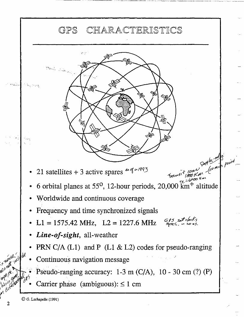
<GIP§ CHARA<C1r1ERJI§1fJIC§
~~ ,,,;pJ ~ /,, ,...,· f"" /-
• 21 satellites + 3 active spares M>1° 1qq3 i~G~~,~~;r!!p
re, ::-&1ff:l0 • 6 orbital planes at 55°, 12-hour periods, 20,000 km+ altitude
• Worldwide and continuous coverage
• Frequency and time synchronized signals
• Ll = 1575.42 MHz, L2 = 1227.6 MHz
• Line-of-sight, all-weather
• PRN Cf A (Ll) and P (Ll & L2) codes for pseudo-ranging
Continuous navigation message '
Pseudo~ranging accuracy: 1-3 m (C/A), 10 - 30 cm(?) (P)
Carrier phase (ambiguous):< 1 cm
© G. Lachapelle (1991)
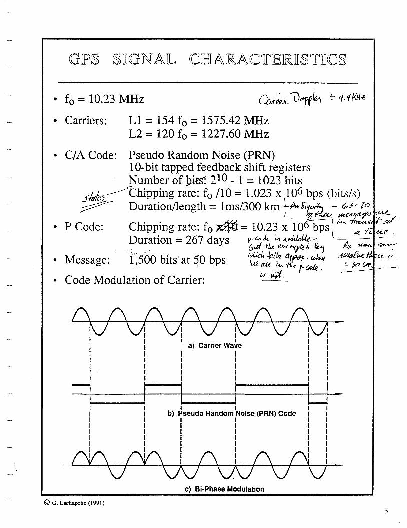
GIP§ §JIGNAIL <CHARAC1fIERJI§1fJI<C§
• f0 = 10.23 MHz Car~ V1'fl&i ~ 'f.'(/41.c
• Carriers: Ll = 154 f0 = 1575.42 MHz L2 = 120 f0 = 1227.60 MHz
• CIA Code: Pseudo Random Noise (PRN) 10-bit tapped feedback shift registers Number of _pits: 210 - 1 = 1023 bits
..rMe2~Chipping rate: f0 /10 = 1.023 x 1106 bps (bits/s)
~ Duration/length= lms/300 km ..\-A>stlh7~ r;,,~-7° /_ t-~'a/ • P Code: Chipping rate: f 0 ~ = 10.23 x 10 bps l ~ A_ •
Duration = 267 days p-ee-k. ~ 11.~ -- A
, ,, . . . . &a!' +u ~t..-,rreJ ~ ~ ~ • Message: 1 500 bits' at 50 bps ~-0~ atf<&t- · w~ t.e
' lu.e. au_ ~ ~ fl.-W,e ~i;:I, ~
• Code Modulation of Carrier: u ·
(\ (\ C\ (\ (\ (\ (\ fV'\J1 \J1\/f\7\JM I I 1
a) Carrier Wa~e I l I I I I I I I I I I I I I I I I I I I I I I I I
1 i i i LJ. b) ~seudo Random
1Noise (PAN) Code I I
I I I I I I I I I I I I I I I I
I I I I I I
1 (\V\I I (\ I (\ (\jl I I I I I I I I I I
VV\./V\/V\J. c) Bi-Phase Modulation
© G. Lachapelle (1991)
3

4
GJP§ §JIGNAIL §JPJE<C1rRUM
•,, f 0 = 10~23 MHz
• Carriers: Ll = 154 f0 = 1575.42 MHz L2 = 120 f0 = 1227.60 MHz
• CIA Code: PRN at 1.023 MHz • P Code: PRN at 10.23 MHz • Message: 1,500 bits at 50 bps
. ;\':\
• : Spr~,aqing. of the code makes it more resistant to i!lt¢,rf erence ' - \ .. ~ \ :,.~<: ' ~*\
© G. Lachapelle (1991)
. , ,
.GPS 'S,ignal Spectrum
2.046 MHz
L1 Signal
C/A Code PCode
1575.42 MHz
20.46 MHz __._.
Spectrum
L2 Signal { Si~ X)
2
1227.6 MHz
20.46 MHz ___.._.
Effect of PN codes modulating GPS L 1 and L2 carrier signals
f
f

. VI
I
GIP§ MIE§§AGIE IFORMA 1f
IBSASTI<C MJESSAGJE 1UNTI1f TIS ONJE IFRAMJE (1500 IBSTI1fS JLONG) 1~---- 30 sec ~
1 IFRAMJE ~ 5 S1UIBSIFTilAMJES 1 2
1 S1UIBSIFTilAMJE ~ 10 WORIDS I 1 I 2 I 3 I 4
1 WORID ~ 30 IBSTI1fS
One fMASTER FRAME I includes all 25 pages of
subframes 4 & 5 = 37 ,500 bits taking 12.5 minutes
© Canadian OPS Associates, January 1988
3
4 I 5
7 18 19 110
Subframes 4 and 5 have 25 PAGES
Cm, Jlf n( vb l! !( .JA-lat!~ ~

6
2
Orbit parameters
Flags (L2 code & data; week#; satellite accuracy and health)
Age of data Satellite clock correction coefficients
Almanac for satellites 25-32 (pages 2,3,4,5,7,8,9,10) Ionospheric model, and UTC data (page 18) Antispoof flag - 32 satellites (page 25) Satellite configuration - 32 satellites (page 25) Health of satellites 25-32 (page 25)
© Canadian GPS Associates, January 1988
Almanac for satellites 1-24 (pages 1-24) Health of satellites 1-24 (page 25)
-......J
@ Hawaii
i
•.
Colorado Springs
© Canadian OPS Associates
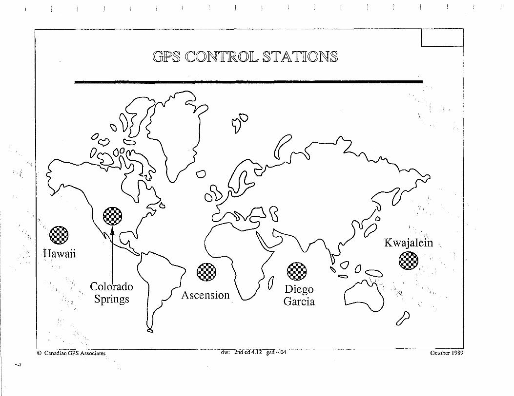
GP§ CCONTIROJL §1rA1rTION§
()
()C\)
))\:)
~~
Kwajalein
@ @ 0 Diego
Garcia
@, ~~~a~. ''\.
I
~
dw: 2nd Cd4:12g5cf 4.04 October 1989

00
CON1rIROJL snrA1fliON JFUNC1fli0N§
/)qfq
/JpJo<Jd , Col],.._
~01
/
~~ J~ ·~~-~· <Q ~· Five monitor stations ~ • Track satellite signals
• Colorado Springs
1~~~~~~~~~--~1~MW~MWM~~
Master Control Station • Process monitor data • Add UTC data from USNO
• Kwajalein • Earth data from DMA • Diego Garcia • Handover data from USAF • Ascension • Generate upload, control data • Hawaii • System management
• Colorado Springs • Vandenburg as backup
© Canadian GPS Associates dw: 2nded 4.new gsd 4.05 October 1989
i

7 .5 year design life 10 year supply of consumables
6 year average life for Block I to date 850kg
(in orbit)
~2x4m
sun-seeking solar array
© Canadian GPS Associates
navigation antenna
1.2 & 1.6 GHz
telemetry & control antenna 1.8 GHz up, 2.2 GHz down
dw: 2nd ed 4.03 gsd 4.06 October 1989
9

JBILO<CJK. ][ SA TJEILILITJES • Space vehicle (SV) numbers 1 - 11 • Intended for research and development of GPS • No Selective Availability or Anti-Spoofmg • Launched between Feb 1978 and Oct 1985
JBILOCK ][][ SA IBILILITIE§
• SV 12 is for ground testing and possible science mission • SV 13-21 launched as production satellites • These satellites still require uploads three times per day • Launching began Feb 1989, continued to Oct 1990
~ JElL~C:v~:'flElLJLilJES ~(ft~ .it'~ • These satellites require only one upload per day
, 1J \ • Launching from late 1990 to 1994
~Mt lBILOCJK Km. SA11EILILITJES fd~ c~ ~ {R6
. sv 41-60 / t( /nt;;f f~ J • "Replenishment" satellites (z.-31£1 ?iit&-!!~ 1-urrk: ) • Ranging between satellites for better navigation / • Launching from 1995
lBILOCJK m §AIBJLILITIE§
• S-V 61-?? • Launching in next century
© Canadian GPS Associates dw: 2nd ed new gsd 4.07 rl: !sd 1.10 pgc 1.10 March 1991
10
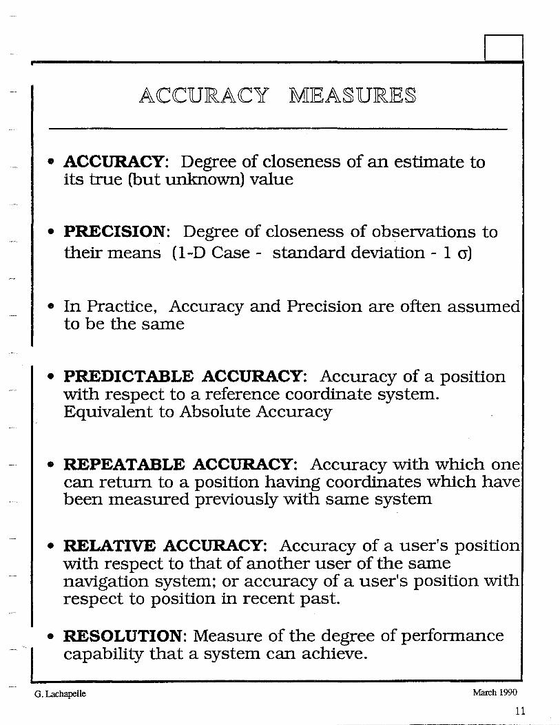
ACCURACY MEASURE§
• ACCURACY: Degree of closeness of an estimate to its true (but unknown) value
• PRECISION: Degree of closeness of observations to their means (1-D Case - standard deviation - 1 cr)
• In Practice, Accuracy and Precision are often assumed to be the same
• PREDICTABLE ACCURACY: Accuracy of a position with respect to a reference coordinate system. Equivalent to Absolute Accuracy
• REPEATABLE ACCURACY: Accuracy with which one can return to a position having coordinates which have been measured previously with same system
• RELATIVE ACCURACY: Accuracy of a user's position with respect to that of another user of the same navigation system; or accuracy of a user's position with respect to position in recent past.
• RESOLUTION: Measure of the degree of performance capability that a system can achieve.
G. Lachapelle March 1990
11

12
n --JDJRMS ANJD CJEJP
• DRMS (Distance Root Mean Squared): 2-D
• One number to express 2D accuracy • Convenient but not as rigorous as error ellipse or full
covariance matrix
• DRMS - [cr2q> + cr2~J 1/2 - Radial Error (Circle) - Mean Squared Position Error (MSPE) - Root Sum Square [£rssl
• Probability of circle with radius drms varies:
• crq> = cr/.v Probability is 63% • crq> = 10 cr/.v Probability is 68°/o
I
• 2DRMS - 2 DEFINITIONS
• 2 x DRMS: Probability between 95.4°!6 and 98°/o [U.S. Federal Radionavigation Plan]
• 2-D RMS: Same as DRMS Above (63 - 68°/o) [NATO's Standardization Agreement]
• CEP (Circular Error Probable)
• Circle with 50% Probability • CEP = 0.59 [crq> + cr)J = [0.62 crq> + 0.56 crA,] • 95°!6 Circle: CEP x 2.08 = 2 x DRMS • 99°!0 Circle: CEP x 2.58
G. Lachapelle March 90
1

CCOMJP ARTISON OIF MEASUIRIE§
. . ' ,\\ 1·. ,, • ', 9901o • oRMs': .. Probapiltfy' of location within an area of
constant!·;radius
• ERROR ELLIPSE: Constant probability, area varies
• THREE-DIMENSION
•Error Ellipsoid: 19.9°A> probability • MRSE: Mean Radial Spherical Error
• MRSE = (cr2cp + cr2'A + cr2h] 1/2 probability of 61°/o .
• SEP (Spherical Error Probable)
• SEP = 0.51 [cr<J> + crA, + crh] probability of 50°/o G. Lachapelle March 90
13

14
DJIILU1rJION OJF JPJRJECJISJION =
• MEASURE OF THE GEOMETRICAL STRENGTH OF A POSITION FIX (THROUGH DESIGN MA TRIX A):
cr' 112 cr' 12 cr' cr' 13 ......... ln
cr'21 cr'222 cr' cr' 23 ........ 2n
D
DOJP
cr' cr' cr' cr' 2 nl n2 n3 ......... nn
• HORIZONTAL POSITIONING: HDOP
HDOP = [cr'2<j> + cr'2jj 1/2 = [l/ cr0 ] DRMS
• 3-D POSITIONING: PDOP
PDOP = [cr'2x + cr'2y + Q"22 ] 1/2 =
= [ cr'2<!> + cr'2t... + cr'2h ] 1 /2 = [ 1 I cro1 MRSE
• 4-D POSITIONING: GDOP (Used with GPS)
-• 1-D (VERTICAL) POSITIONING: VDOP = cr' h
• ABSOLUTE POSITIONING ACCURACY: DOP x UERE
• UERE: User Equivalent Range Error ©G.Lachapelle/1990

GIP§ CCIHIARACC1rIEJRJI§1rJICC§ ANJD §JINGJLIE IPOliN1r IPIERIFORMANCCIE$
Satellite Satellites
Constellation Orbital Characteristics
Signal Structure
F uencies
Digital Signal
Other
(SPS, Cl A Position code,95%) [PDOP~.O] Velocity
Tlll1C
(Ll/L2 p code, 95%) Position [PDOP~3.0]
(Anti-Spoof- Velocity ing Off, Tune Civilian receiver)
© G. Lachapelle (1991)
21 satellites + active spares Satellites broadcast si als autonomous! 6 planes, 4 satellites per plane _ 55 de inclination, 12-hour eriod, 20,231 km altitu e Dual L-band (1575.42 MHz, 1227.6 MHz) Spread spectrum PRN, C/ A code@ 1.023 MHz, P code @ 10.23 MHz Continuous navi ation messa e@ 50 Hz
Worldwide Selective Availability
On Off
100 m .,......q51oi.~ 20 to 30 m 156 m rdBf- 30 to 45 m ---
0.45 m s-l' 0.3ms-l
300 ns ~ 40 ns
1A Wt,·Ji 100 m (P~~tU~ 15 to 25 m ~ 156m av°6 20 to 30 m -
0.45 m s-i'"J.NI) 0.1 m s-1
300ns ~ 30ns
Horiz: Vert:
Horiz: Vert:
15

16
§JEILIECC1LJIVJE AV AJIILAJEJIILJI1LY
• Two types: £-type (orbit) and 8-type (clock)
• £-type: Injection of additional orbital errors (dpsa)
Range Error of 50 - 150 m ...--oBS~v~u-~ Rapid Variation in Range Error
• dPsa results in additional DGPS errors and may shorten the distance M-R over which the ambiguity integer numbers can be effectively recovered.
~t?f~4· • 0-~ype: Injection of errors in the ~tel!ite al clock term:
• ,dT = Litsv + Et(residuals) 9~[ a_~-~~,~ ~5A < • Litsv = ao + ai(t - toe) + a1 (t -'t0c)2
• Range rate error variation of up to 25 cm/s
• Observed SA in April 1990 [1]: mostly 8-type !
..
t·
-0 en en ,.. cD c... ;::: c. ct -(/) tu
50
:::s Cl) 0 "C Q) ·- .. (/) -Cl.> Q)
a: :: Cl.> C) c: ~ -50 0 "C :::s Cl.> (/)
a.
::::;
t\li't ~~J<J\:,PRN 17
.:: PAN 19 l
PRN12
PRN18
-100 ..___.___...__..___..___._ _ _,__~----i-_..._ ..... 108 109 110
Hour of GPS week 537
[l] B.W. Tolman et al. (1990) The Effect of Selective Availability on Differential GPS Positioning, Proceedin s GPS90, Inst. of Navi ation, Wash., D.C., . 579-586 © G. Lachapelle (1991) KIS 90

• §1r AND.AJR]) IPO§TI1rITONTING §JEIRVTICIE (§IP§)
• Affected by Selective A vailabilty (SA) and Anti Spoofing (AS)
• Ll only, lower accuracy CIA code {PRN of 1.023 MHz}
• Accuracy with SA On:
• 100 m (<t> and A.) 2DRMS (95%) or • 40 m ( <t> and A.) CEP (50%) • 156 m (h) 2cr (95%) • 76 m (<f>, A. and h) SEP (50%)
[76 m SEP = 100 m 2DRMS = 40 m CEP]
• Ll/L2 Civilian P code
• Affected by SA • Accuracy marginally better than above • Not available when AS is on • Lower noise, ionospheric effect removed,
better multipath resistance
• lPJRJECli§JE lPO§li'fliONliNG §1EJRVKCJE (lPlP§)
• Cryptographic key to remove SA and AS • DoD and DoD authorized users only • CIA Code: 30 m - SEP
• P /Y Code Accuracy Full accuracy:
• 16m (<f>,A.andh) · SEP (50%) { i
© G. Lachapelle /1991
17

18
/ DGJPS <CON<CEJP1'
Monitor (fixed) GPS Receiver
• ADVANTAGES
(i) Reduction and/or elimination of errors
• Orbital • Ionosphere and troposphere • Selective Availability
(ii) Better quality control
:. REMAINING ERRORS
• Receiver noise ·• Multipath • Troposphere
© G. Lachapelle (1991)
OnboardGPS Receiver and
Remote Sensing Unit(s)
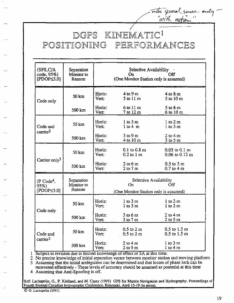
DGlP§ KJ[NIEMA1rJ[CC1 1P0§J[1rJ[ONJ[NG lPIEIRIFOIRMANCCIES
(SPS,C/A Separation Selective Availability code, 95%) Monitor to On Off [PDOP~.O] Remote (One Monitor Station only is assumed)
50km Horiz: 4to9m 4to8m
Code only Vert: 5tollm 5to10 m
500km Horiz: 6to11 m 5to8m Vert: 7to12m 6to10 m
50km Horiz: 1 to3 m 1 to2m
Code and Ven: 1 to4 m 1 to3 m carrier2
500km Horiz: 3 to9m 2to4m Vert: 4to10 m 3 to5 m
50km Horiz: 0.1to0.8 m 0.05 to 0.1 m Vert: 0.2 to 1 m 0.06 to 0.12 m
Carrier only3 Horiz: 2to6m 0.5 to 3 m 500km Vert: 2to7 m 0.7 to 4 m
(P Code4, Separation Selective Availability 95%) Monitor to On Off [PDOP~3.0] Remote (One Monitor Station only is assumed)
50.km Horiz: 1 to3 m 1 to2m Vert: 1 to3 m 1 to2m
Code only
500km Horiz: 3 to6m 2to4m Vert: 3to7 m 2to5m
50km Horiz: 0.5 to 2 m 0.5 to 1.5 m Code and Vert: 0.5 to 2 m 0.5 to 1.5 m carrier2
500km Horiz: 2to4m 1to3 m Vert: 2to5 m 1 to4m
Sub 'ect to revision due to limited knowled e of effect of SA at this time. 1 ~ g 2 No precise knowledge of initial separation vector between monitor station and moving platform 3 Assuming that the initial ambiguities can be determined and that losses of phase lock can be
recovered effectively - These levels of accuracy should be assumed as potential at this time 4 Assuming that Anti-Spoofing is off.
Ref: Lachapelle, G., P. Kielland. and M. Casey (1991) GPS for Marine Navigation and Hydrography. Proceedings of Fourth Biennal Canadian h dro hie Conference. Rimouski. A ril 15-19 in ss). © G. Lachapelle (1991)
19

20
-oo•._..._.__...__.___....__._..__.__,_.__.__._.....__.._.____.__,__.._._.__.__._..__.
-1so• -120• -60• 0° 60• 120• 100•
Typical Ground Tracks (After Santerre, 1989)
VDOP at <t> = 50° (21 + 3 Constellation)
4
2
0 7.0 13.0 19.0 1.0
VDOP at <t> = 90° (21 + 3 Constellation)
4
(\ \t/\;WV\ 2 ,J Li 0 7.0 13.0 19.0 1.0
7. (
7.0 SANTERRE. R. (1989) GPS Satellite Sky Distribution: Impact on the Propagation of Some Important Errors in Precise Relative Positionin . Technical Re rt No. 145. De t. of Surv. Eng .• The Univ.of New Brunswick.
© G. Lachapelle (1991)
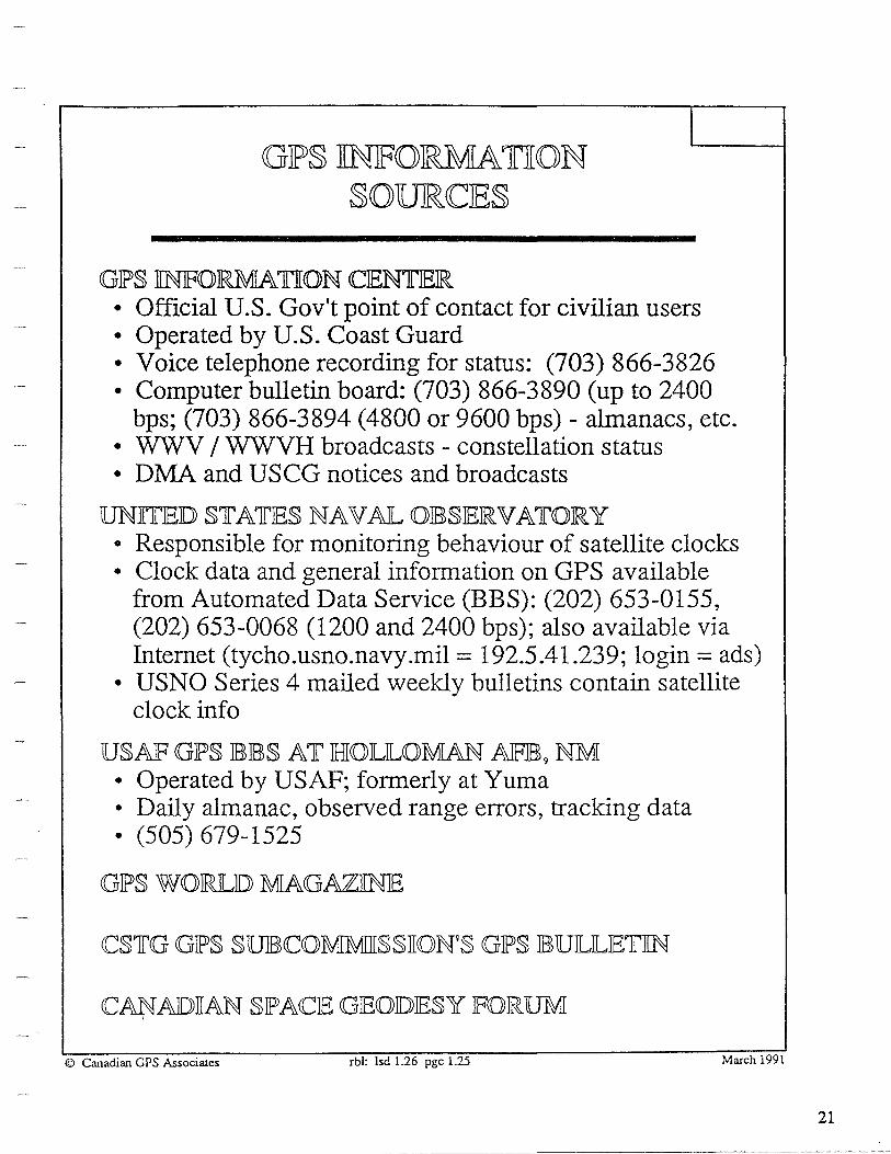
GIP§ JINJF\O>RMATION §OUJRCCJE§
GJPS nNJFORMATION ClEN1IJEIR.
I
• Official U.S. Gov't point of contact for civilian users • Operated by U.S. Coast Guard • Voice telephone recording for status: (703) 866-3826 • Computer bulletin board: (703) 866-3890 (up to 2400
bps; (703) 866-3894 ( 4800 or 9600 bps) - almanacs, etc. • WWV I WWVH broadcasts - constellation status • DMA and USCG notices and broadcasts
UNITJED STATIES NAV AJL OJBSIEIRVATOIRY • Responsible for monitoring behaviour of satellite clocks • Clock data and general information on GPS available
from Automated Data Service (BBS): (202) 653-0155, (202) 653-0068 (1200 and 2400 bps); also available via Internet (tycho.usno.navy.mil = 192.5.41.239; login== ads)
• USNO Series 4 mailed weekly bulletins contain satellite clock info
USAJF GJPS JBJBS AT JHIOJLILOMAN AJFJB 9 NM • Operated by USAF; formerly at Yuma • Daily almanac, observed range errors, tracking data • (505) 679-1525
GJPS WOIRJLD MAGAZ1IN1E
© Canadian GPS Associates rbl: lsd 1.26 pgc 1.25 March 1991
21

GJLONAS§
GLONASS Technical Characteristics
Satellites 21 satellites + 3 active spares
Satellite Satellites broadcast signals autonomously Constellation Orbital 3 planes, 8 satellites per plane
Characteristics 64.8 dw inclination, 11hr15 min period, 19,100 km altitude
Freauencies Dual L-band (1597-1617 MHz, 1240-1260 MHz) Signal Digital Spread spectrum PRN @511 KHz chipping rate
Structure Signal Continuous navigation message@ 50 Hz
Other FDMA signal separation fi = Fl + (j-1) M M = 0.5625 MHz, j = 1. .. 24
Coverage Worldwide Position 100 m horizontal, 150 m vertical (S.A. on)
Accuracy Velocity 0.15m/s Time 1 microserond
G. Lachapelle/March 90
22

GIP§ & liNMAR§A1fv§ GIE0§1fATXONARY OVIERJLAY
• Similar concept to RDSS (e.g., Geostar & Locstar)
• Use Repeaters on Insarmat-3 satellites (Launching: ..... 1995)
• GPS-(and/or GLONASS) like code uplinked from the ground at a C-band frequency, e.g. 6.4 GHz)
• Typically 3 satellites on geostationary orbits at 35,000 km
• Extensive Inmarsat ground tracking network used to determine satellite positions
• Ranging with a GPS receiver on downlink at GPS LI frequency - Improve GPS geometry & coverage
• ~O bps data stream modulated on carrier could transmit GPS and GLONASS integrity information
Kinal, G. V., and J.P. Singh (1990) An International Geostationary Overlay for GPS and GLONASS. Navi ation, Vol. 37, No. 1, Washin on, D.C., . 81-93 © G. Lachapelle (1991) The University of Calgary
23


JFUNJDAMJEN1rAILS OJF GJPS lili
USIER IEQUKJPMIEN'f
• Antenna Characteristics
• Antenna Gain Pattern and Phase Center Properties
• Receiver Characteristics and Classification
• Pseudo-Range and Carrier Measurements
• Correlation, Squaring and Codeless Channels
• Cost Trends
RJEAlL= TKMJE JDKJFJFJERJENTKAlL Glf»S
• Differencing of Pseudo-Range and Carrier Observations
• Effect of Selective Availability on DGPS
• RCTM SC-104 GPS Correction Message
• Date Link Types and Classification
• DGPS Reference Station Software
• Sample DGPS Differential Systems
AV AKlLAJEKlLKTY ANJD KNTJEGRKTY JISSUIES
G. Lachapelle (1991)

D
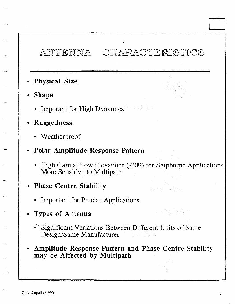
ANTJENNA CHARACTJERli§TliC§
• Physical Size
• Shape
• Im po rant for High Dynamics
• Ruggedness
• Weatherproof
• Polar Amplitude Response Pattern
• High Gain at Low Elevations (-200) for Shipbof!Ie AppHcations More Sensitive to Multipath
• Phase Centre Stability
• Important for Precise Applications
• Types of Antenna
• Significant Variations Between Different Units of Same Design/Same Manufacturer
• Amplitude Response Pattern and Phase Centre Stability may be Affected by Multipath
G. Lachapelle /1990 1

-------·-----------------------------
2
Dipoles and shaped dipole arrays
Spiral helices .
Null or beam steered arrays
© Canadian GPS Associates, January 1988
Quadrifilar helices or volutes
Micros trip patches
Cavity backed planar spirals
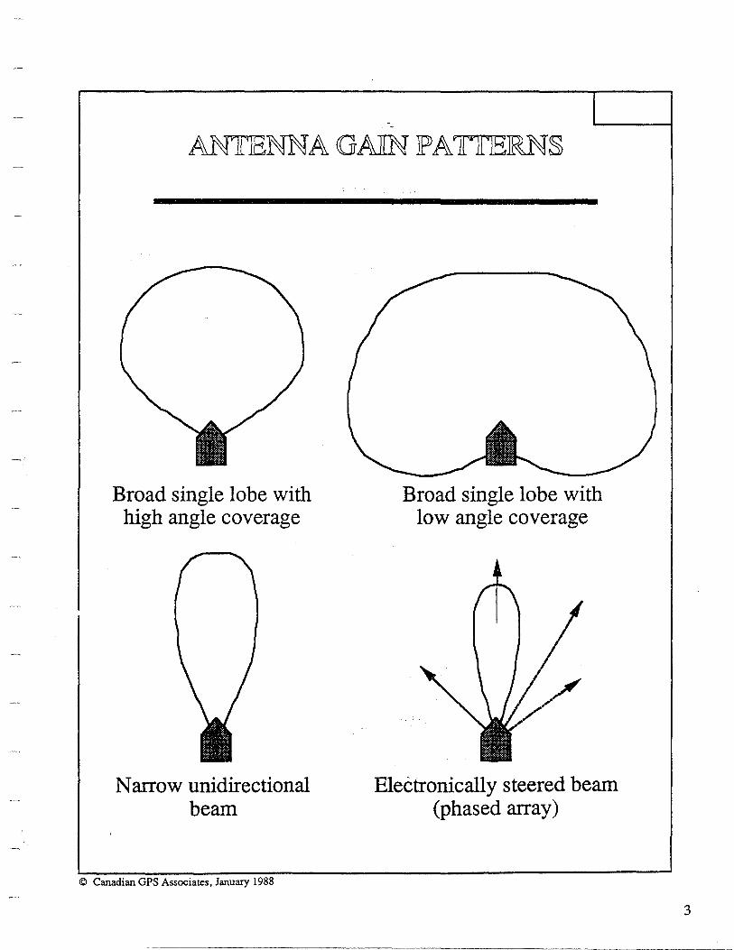
Broad single lobe with high angle coverage
Narrow unidirectional beam
© Canadian GPS Associates, January 1988
Broad single lobe with low angle coverage
Electronically steered beam (phased array)
3
-----------------------·-

-··---·----------------------------------
4
-GROUNDJPLANJE IE1FflEC1r§
Antenna
Antenna
__,,,,,,, Back lobes
"
© Canadian GPS Associates, January 1988
Smooth single lobe / pattern
Small groundplane
Peaked multi-lobed ~pattern
""Large groundplane

ANTIENNA~JPHASIE
JPJRO PIER TIDES
1r ANGIENT SJP'JHIIERIE MTIE11"1HIOID AND JBIES1r lFJI1r 1P'HASIE
----- Best fit spherical Best fit centre equiphase contour of phase variation
\ Equ1phase contour
MJIN1MUM V AIEUA TION CIEN1m.JE 01F JR.OT ATION MIE1rIHIOID
Antenna
~---
© Canadian GPS Associates, January 1988
Measurement rotation axis
Centre of best fit circle
Phase curve
5

6
D-
RECCEKVJER CIHIARACCTJERli§TliC§
• Size, Power, Ruggedness, Reliability, Self Check, Interfaces for External Sensors, L2 Capability on Carrier
• Number of Channel
• Up to Wwm contribute to Reliability Improvement
• P versus Cl A Code
• P code (Ranging) more precise and better multipath resistance, but Anti-Spoofing implemented on an Intermittent Basis
• L2 Squaring now Available on Cf A Rx Anyway
• Continuous Carrier Phase Data
• Required for accuries < 5 m in DGPS Mode
• Output of Raw Data
• High data rate ( < 1 Hz) for More Effective Cycle Slip Detection and Vehicle attitude Modelling
• Tracking Bandwidth
• Wide Range for Different Dynamics to Maintain Phase Lock and Optimize Accuracy
© G. Lachapelle /1990

GJP§ RIECIEKVIER CCILA§§KIFKCA 1LKON
Measuring Techniques
No. Class
1 C/A code Ll
2 L2 squaring
3 L2 codeless
4 P codeless
5 P code
Characteristics
Code only or code and carrier phase
Carrier phase on L2 by squaring (1/2 original A., i.e., 12 cm) No P code required
Carrier phase on L2 by Ll/L2 correlation 1 (original A., i.e., 24 cm) ~JC
P(L 1) and P(L2) correlation {Qft ,,,-provides absolute ionospheric group _ , J/ delay without access to P code / ,,- tr; 0 ,
Code and c~rrier on Ll and L2 J f 5tPr~ f111yt
P code reqmred t,tf1 JM \lr \
Sample Classification - eodetic Receivers
Receiver
Allen Osborne Rogue Series Ashtech L-XII Ashtech LD-XII Ashtech P-XII Ashtech 3DF Magnavox 42000 t iiitO Mini-MacTM 2816 Motorola Golden Eagle Sercel TR5S Trimble 4000SD Trimble 4000ST
Nbr o Channels/ Sat ites Tracked
8 satellites 12 12 12 + 12 6 x 4 antennae 6 8 satellites 4 5 5+5
TRIMBLE Geodetic Surv. IIP WM102
8 + 8 or 12 + 12 8 satellites 7 + l (6 satellites)
© G. Lachapelle (1991)
Class( es)
1, 3, 4, and 5 1 1 and 2 1, 2, and 5 (Ll &L2) 1 - multi-antenna 1 1and2 1 1 1 and2 1and2 1and5 (L2) 1, 2 and 5 (L2)
7

00
3.27.
GJENJEJRJ[(C GIP§ MCJEliVJER ~h
Antenna // ,/
d V anu ' Preamplifier
Memory .,. Code Command
~ tracking .... II..
& display ~ ' [L ... rr
'"' loop • ~ unit '~
... Micro- .A
r -...
,, processor
Carrier Data " ·tracking ·-" " & control ., ,,
loop Power
port
supply
© Canadian OPS Associates rl: pgc 3.27 March 1991

\0
1rnA<CKKNG JLOOJP§ liN GJP§ IRJECIEliVJEIR.§
IPIHLASJE lLO<CIK lLOOIP
Incoming Phase VCO si nal com arator generator
Phase
Error signal Control
Output (carrier replica)
Reference signal
Phase offset Received signal
. ~ ... t • ... .. '- r ' -I f 4C »
© Canadian GPS Associates, January 1988
lDJElLA Y lLO<CIK lLOOIP
Incoming Correlation Code signal com arator generator
Error signal Control
Local clock
t------4
Reading of ... , local clock
l---1 Time delay
Reading of .. . satellite clock
Note: In general the 2 clocks are not synchronized!

10
JP§JEUJDO=RANCGJE OJE§JERV AJEILJE
Satellite clock
GPS time
I I 11 · I Receiver clock
r dt ·I d't = p / c 1 ,..___--<>----~--.....
p/c
• Pseudo-Range Observation Equation
p = p + dP + c (dt - dT) + dion + dtrop + E(p)
P = II r - Rll dP (orbital errors) = dPn + dPsa dpn .. nominal (broadcast) orbital error component (5-25 m) dPsa ... orbital error component due to S.A. dt, dT ... satellite & receiver clock errors dion, dtrop ... ionospheric & tropospheric delays
E(p) ... f{E(prx), E(pmult)} E(prx) ... r ceiver code meas. noise (Gaussian)
E(prx[c/a]) z I 3 m; E(prx[PJ)::::: 10 - 30 cm E(pmult) < 1 chi (non-Gaussian)
©Lachapelle, The University of Calgary (1991)
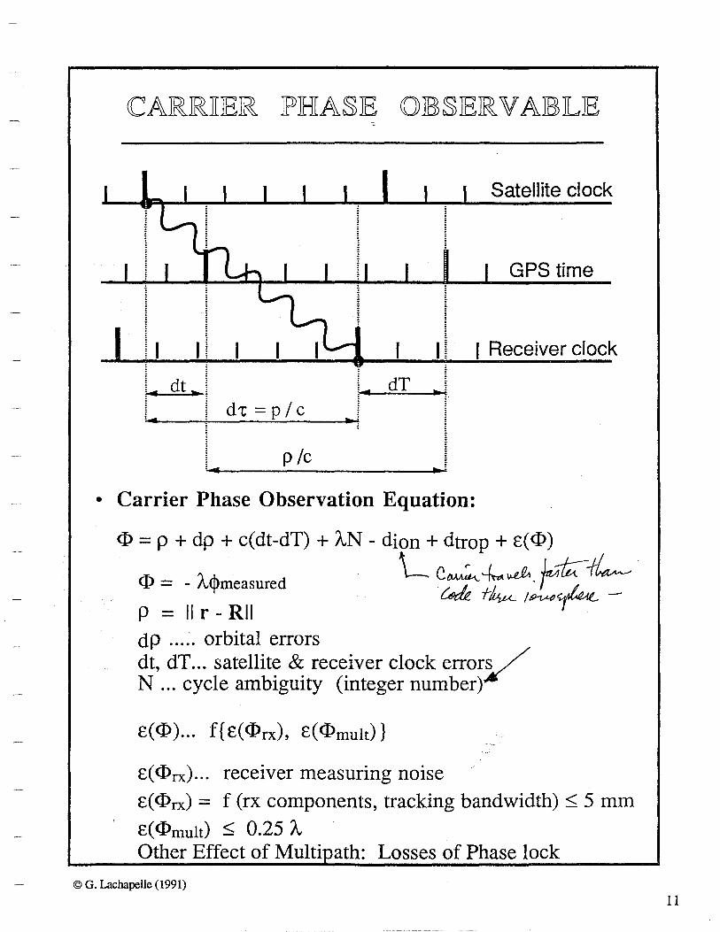
CARRTIJER IPHA§IE OJE§IERVAJElJE
Satellite clock
GPS time
I I I I I ! I Receiver clock
,_i .. _d_r_ .... _i _d_t ___ P_~-;c __ r dT 1 • Carrier Phase Observation Equation:
<I>= p + dp + c(dt-dT) +AN - <lion+ dtrop + E(<I>)
<I> = -A<j>measured L c~--/... .J.,. r-t;::' L ~ f/vµ_ 1~,...Lo"" -
P = II r - R II ,~~~
dP . . . . . orbital errors dt, dT ... satellite & receiver clock errorV N ... cycle ambiguity (integer number)
E(<I>) ... f{E(<I>rx), E(<I>mult)}
E( <I>rx)... receiver measuring noise
E(<I>rx) = f (rx components, tracking bandwidth)< 5 mm
E(<I>mult) < 0.25 A Other Effect of Multi ath: Losses of Phase lock
© G. Lachapelle (1991)
11

...... N
<CORRIEILA 1fliON CCJHIANNJEJL :: ,:,..-~
/~~<(
""' "'11 ... 1
""'
Code tracking loop
Stable oscillator
© Canadil:!n GPS Associates, January 1988
Outputs
""' ···Message ... ~ ·1--..... llMI qeffioc1\ilat9f .... ___. ... ~,
Clock Time
interval Pseudorange

Beat carrier and code
Oscillator
© Canadian GPS Associates, January 1988
Phase inversions (code steps)
Output
Squared a--1....i beat carrier
(no code)
13

...... +:>.
. I
66CCODJEILJE§~99 liONO§JPJHIJEruc DIEJLA y
Stable oscillator
"" .....,
""
""
L2+Pcode
© Canadian GPS Associates, January 1988
)
Ll+P code
.... 1 Correlator
P(L 1) vs P(L2) code correlation
loop
delay delayed L2+P code
.,'" (
Output
,er Ionospheric -----------------1~ group delay

CIA CODJE GIPS ~ SIPJECJIJFJ[CCA1rJIONS {JEXAMIPJLJE)
• IPO§§TIJBTIJLJE U§JEJR §JP'JECJTIFliCA 1rTION§ IFOJR AKRJBORNJE SURVJEYKNG AJPJP'ILKCA1rKONS
Description
Weight Power Voltage Number of parallel channels Continuous carrier phase on L 1 Ll C/A code accuracy Carrier phase accuracy Doppler frequency and accuracy Codeless on L21 Data rate Time mark External sensor trigger Interfaces/guidance and data logging Loss of phase lock indicator Real-Time DGPS capability Maximum dynamics Waypoint navigation Aircraft fuselage antenna mount Antenna gain pattern Antenna phase center stability
Specification
< 10 kg < 15W 24 V, DC >8 Yes <2m <5mm Preferable,< 0.01 Hz For sub-metre accuracy <ls 1 s interval, < 0.1 ms Yes,< 1 ms Yes Yes Preferable v: 200 ms-1, a: 2 g's Yes Yes -100 to 1900 < 1 cm
1 Provided that proper codeless mechanization is used
G. Lachapelle (1991) Capabilities of GPS for Airborne Remote Sensing. Can. Journal of Remote Sensing, Vol. 17, No. 4, Canadian Aeronautics and Space Institute, Ottawa (in press).
© G. Lachapelle (1991)
15

16
RIE<CIEJIVIER <CJHIJIJP <C0§1L 1LRIENDS
• ADV AN CED TECHNOLOGY PROGRAMS
• VHSIC (Very High Speed Integrated Circuit): Initiated mid 80's; reduction of component geometry, higher processing speeds; lower power comsumption; clock speeds of 100 MHz expected to be available by 1995.
• MIMIC (Microwave/Millimetre Wave Monolithic Integrated Circuit): Initiated in 1990; development of RF circuits on single Gallium Arsenide (GaAs) chips; potential clock speeds of 100 GHz.
2.0
1.5 T H
$ 0
1.0 u u s
A 0.5 s N
D s
0.0
1988 1991 1995 1997
Kra.ld,wsky, E.J., G. Lachapelle, and K.P. Schwarz (1990) Assessment of Emerging Technologies for Future Navigation Systems in the Canadian Transportation Sector. Report No. 60007, Department of Surveying Engineering, The University of Calgary.
© G. Lachapelle. The University of Calgary

RIEAJL= 1rliMIE JDGJP§ -_ OJPIERA 1rli0N§
• Trarismission of differential corrections or raw data from Monitor (known position) to Remote station(s)
• Differential pseudorange corrections for positioning accuracies of 2-5 m (50 - 100 bits per second«)
• Raw carrier phase and pseudorange observations for positioning accuracies< 1 m (1,000 - 2,000 bps)
• Data link requirements are a function of:
• Amount of data to be transmitted • Reliability and Integrity requirements • Distance between Monitor and Remote
• Only algorithms and software which can work in re~-time can be used (e.g., filtering)
• Effect of Selective Availability:
• More frequent updates of differential corrections • More rapid error growth as a function of separation
between Monitor and Remote stations
• RTCM SC-104 Standard format for data transmittal
• Can use different types of receivers
• Monitor station receiver should have "all-in-view" tracking c~pability (10 channels) if DGPS operations are over a wide
area
© G. Lachapelle/M.E. Cannon, The University of Calgary, 1991
17

18
• Between Receivers Single Differences:
~p = ~p + ~dp - c~dT + ~dion + ~dtrop + ~c(p) ~<I>= ~p + ~dP - c~dT + A.Llli - ~dion + ~dtrop + ~c(<I>)
• Reduces Orbital and Atmospheric Errors (20 m orbital error - 1 ppm on baseline)
• Does not reduce c(p)'s or c(<I>)'s
{ c(p )rxl and c(p )rx2 are uncorrelated}
• ~p Method used for Real-Time Applications:
• Averaged 8p's and d8p/dt's are transmitted from Monitor to Remote (Mobile) at regular intervals with a data link:
• RTCM SC101 Specifications: 50 - 100 bps data rate • Accuracy: 1-5 m (phase-smoothed pseudoranges)
© G. Lachapelle (1991)

JEJFJFJE<C1f 0 JF §JEJLJE<C1fJIVJE AV AJIJLAJBJIJLJI1fY
ON RJEAJL 1fJIMJE JDKGP§
• DGPS Corrections Every few Minutes when S.A. is Off
• Effect of S.A. on Update Rate (After RTCM SC-104):
10 .
0 10 20 30
Time Since Update (Seconds)
DGPS Error Growth due to Selective Availability
40
• 50 bps is assumed (transmission of pseudorange [or phase smoothed pseudorange] and pseudorange rate)
• Higher data rate required if a higher level of accuracy is Tequired
© G. Lachapelle, 1991
19

20
GJP§ CCORRJECCTJION MIESSAGJE JFORMAT
Word 1 I Word 2 Message
'/ t General message 16 MIESSAGIE ilYIPIES
information
1 Differential corrections 2 Delta differential corrections 3 Station parameters 4 Surveying 5 Constellation health 6 Null frame 7 Beacon health 8 Pseudolite health 9 High rate differential corrections 10 P-code differential corrections 11 C/A-code Ll,L2 differential corrections 12 Health message 13-15 To be decided 16 Special messages
© Canadian GPS Associates. January 1988
15.4

Corrections to G PS pseudoranges in the form
d p(t) - dp(t0 ) + d a p ;at ct - t 0 ) . ~ ' .
'/ Pseudorange "I / R . "I ange correction \..
correction ...
Satellite Satellite ID health
\.. rate of change
Estimated user range
error
Issue of data
Corrections to Type 1 data in the form
...
d p(t) = dp(to) + d a p/at (t - to)+ dpdata
• I
I /
Delta ( Fill I parity ) correction
\... ...
Always used to augment a Type 1 message
© Canadian GPS Associates. January 1988
15.5
Fill and
parity
21
N N
© ~l' p g a.
i • (Tq
1-1§ o .. ZC'J O> '"O. .... Cf.l ..
~ ·~ .... '° . ~~ Cl) 0 rca o ..
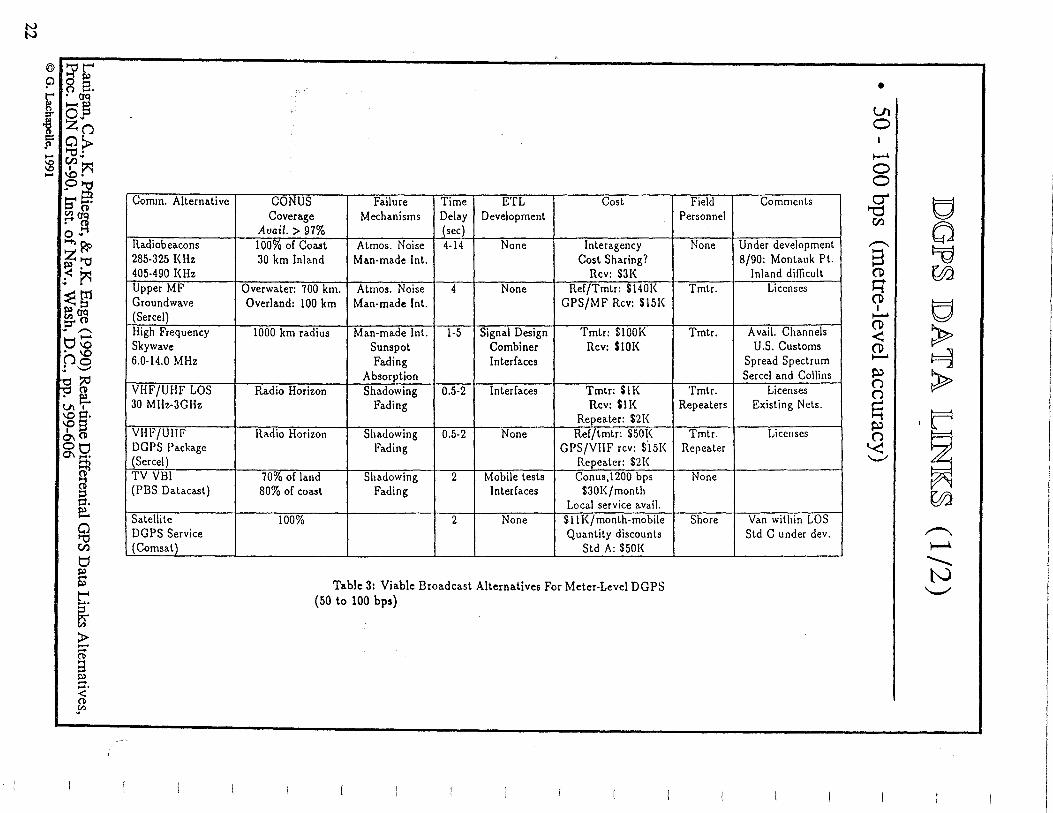
Conun. Alternative
>-+) ~
z'"O ~· .: ~ ~g1 ~~ ::r .. -.. tJtO . '° C'Jo .: '-"
Radiobeacons 285-325 KHz 405-490 KHz Upper MF Groundwave (Sercel) High Frequency Skywave 6.0-14.0 MHz
~ . e. ti\ I
~a· °' 0
VHF/UHF LOS 30 Mllz-3GHz
VHF/Ullf OtJ 0\ I=;; ~ d :::3
DGPS Package (Sercel) TV YB! (PBS Datacasl)
p. e. 0 '"O Cf.l
Satellite DGPS Service (Comsat)
t:1 s:i> .... s:i>
r. ~ > -.... ('ll a s:i> .... .... < ('ll ,yi
CO NUS Failure Time ETL Cost Coverage Mechanisms Delay Development
Avail.> 97% (sec) 100% of Coast Atmos. Noise 4-14 None lnteragency 30 km Inland Man-made Int. Cost Sharing?
Rev: $31< Overwater: 700 km. Atmos. Noise 4 None Ref/Tmtr: $1401< Overland: 100 km Man-made Int. GPS/MF Rev: $151<
1000 km radius Man-made Int. 1-5 Signal Design Tmtr: $100K Sunspot Combiner Rev: $101< Fading Interfaces
Absorption Radio Horizon Shadowing 0.5-2 Interfaces Tmtr: $11<
Fading Rev: $11< Repeater: $2!<
Radio Horizon Shadowing 0.5-2 None Ref/tmtr: $50!< fading GPS/V!IF rev: $.151<
Repeater: $2!< 70% of land Shadowing 2 Mobile tests Conus,1200 bps 80% of coast Fading Interfaces $301</month
Local service avail. 100% 2 None $11 !</month-mobile
Quantity discounts Std A: $501<
Table 3: Viable Broadcast Alternatives For Meter-Level DGPS (50 to 100 bps)
• Ul 0 I
~
0 0
Field Comments Personnel
None Under development 8/90: Montauk Pt.
Inland difficult Tmtr. Licenses
~I g ~ ,,---. ~ s
(t> ~ q
Tmtr. Avail. Channels U.S. Customs
Spread Spectrum Sercel and Collins
Tmtr. Licenses Repeaters Existing Nets.
Tmtr. Licenses Repeater
None
(t> g I ......... (t> > <! (t>
~ ....... ~ > (J (J
~ "r ~ t==l (J
~ '-<! '--'
~ Shore Van within LOS
Std C under dev. ,,,-...... 1--l ......._ N
'-_.-'

I
~ ~~ pg . t'"' • (Jq
~ ....... § :1' o .. i Zn ;: 0).. • "ti • .... Cf.I .. :g I ~ .... '°. ~~ fl) 0 ~°8 o.!'1
Comm. Alternative
""+)~
~'"d f ~ ~tI1 ~Jg ::;rO
Upper MF Groundwave (Sercel) Iligh Frequency Skywave G.0-H.O Miiz
.. ,-...
t1 G (J~ .! .._,
~
·~ (Ji I
~s· 6'o ~~ ~ i:t.
VllF/UllF LOS 30 Mllz·3Gllz
VllF/UllF DGPS Package (Scree!) TV VU! {!'OS Datacasl)
Satellite Dedicated channel
r:.. (AMSC)
~ Cf.I
t:1 P> s c ~ > -.... '1 0 3 P> p. < 0 fl)
L: N ~
CON US Failure Time ETL Cost Coverage Mechanisms Delay Development
Avail> 97% (sec) Overwater: 410 km. Atmos. Noise 4 Modify equip. Ref/Tmtr: $140K
Overland: 50 km Man-made Int. for higher CPS/MF Rev: Sl5K data rate
100 km radius Man-made Int. 1-5 Signal Design Tmlr: $1001< Sunspot Combiner Rev: S!OI< Fadiug !11Lerfaces
Ahsorption
lla<lio Horizon Shadowing 0.5-2 Interfaces Tmtr: $11\ Fading Rev: $1 I<
Repealer: $21< Hadio llurizou Shaclowiug 0.5·2 None llcf/tmtr: $501<
Fadiug CPS/Vil F rev: $151< Repealer: $21\
70% of land Shadowing 2 Mohile tests Couus,2400 hps 80% of coast Fading Interfaces $331</month
Local service avail. 100% 2 Interfaces 25% Conus
2400 bps $7.51</month
Terminal: $41<
Table 4: Viable Broadcast Alternatives For Decimeter-Level DCPS (1000 to 2000 bps)
• >--" ... 0 0 0 I
N Field Comments
Personnel
Tmtr. Licenses
Tm tr. Avail. Channels
g ... 0 0
~ 0 cr' FQ >-a
~ Cf.I
US Customs Spread Spectrum
,,..-..... g 0..
(J) Minimize Data Rate Sercel and Collins
Tm tr. Licenses Repeater Existing Nets.
~ ()
§'
~ (J) q (J)
Tmtr. Licenses llepeater
None
Nouc 3 to 4 years
I ,,r .......... (J)
< ~ (J)
~ ..........
~ ()
~ ~ ~ ,,--.... :$1 N
............. N "-/

24
DI[JFJFJERIEN1f1[AL <GIP§ RJEJFJERJEN<CIE §1rA1fXON §OJFJrWARIE (1/2)
• Used at the monitor station - DGPS kinematic applications
• Example: Magnavox 4818 all-in-view [Sharpe, 1989]
• Input: phase-smoothed pseudoranges using recursive filter of Hatch [1982] {no loss of dynamic response}
• Two-state (offset & drift) Kalman filter for clock - can be tuned to any time & frequency standards (useful for operation under Selective Availability)
• Two-state (range corr. and rate) parallel filters for satellites
• RTCM SC-104 standards for differential GPS service
CLOCK COMPUTED KALMAN SATEUITE FILTER
RANGES .---ESTIMATED
1 RECEIVER CLOCK OFFSET
~ SAT 1 SATEWTE 1 CORR
- CORRECTION KALMAN FILTER RATE
SAT 2 SATELLITE 2 CORR - - CORRECTION KALMAN FILTER RATE •
• • • • • ' SAT N SATELLITE N CORR
- - CORRECTION KALMAN FILTER RATE
MX 4818 Pseudorange Correction Processing
Sharpe, R.T. (1989) The Magnavox 4818 All-in-view Differential GPS Reference Station: Descri tion and Test Results. NAV89 Conference, R.I.N., London, Oct. 1989
© G. Lachapelle, 1991
CORRECTION FORMAmNG AND OUTPUT

JDJIJFJFIERIENTJIAIL GP§ JRIEJFIERIENCIE S1rA1rJION SOJFTW ARIE (2/2)
• Differential corrections for Block I and II (SA) satellites:
iii' a: ... I-... ~ Cl)
z c:>
6 ... a: a: c:> u ... C!J z ct a: c:> c :::> ... Cl) Q,.
JD.--~~~~~~~~~~~~~~~--.
20
10
-10
-30
-50
-70
-90
-110
-130
-150
-170
-190
-210 0.0 0.4
MX 4818 PSEUDORANGE CORRECTIONS LOS ANGELES, CA, 20 SEPTEMBER 1989
~ '-........ PRN 14
0.8 1.2 1.6 2.0 2.4 2.8
TIME IHOURSI
• Effect of low (60s) update rate on DGPS positions:
50 40 DGPS NAY ERROR 60 SEC CORRECTION RATE
30 LOS ANGELES (NAY} HOUSTON (REA 17 SEP 89
20 10 0
-10 -20 50 -30
AVG = 4.6 40 STD = 3.2
-40 30 -50 20
0 20 40 60 10 TIME (MINUTES) 0
-10 50 -20 40 -30 AVG = 1.7 30 -40 STD = 20.1 20 -50 10 0 20 0 TIME (MINUTES}
-10 -20 -30 AVG 3.4
-40 STD = 3.4
-50 0 20 40 60
TIME (MINUTES)
© G. Lachapelle, 1991
40 60
25
26
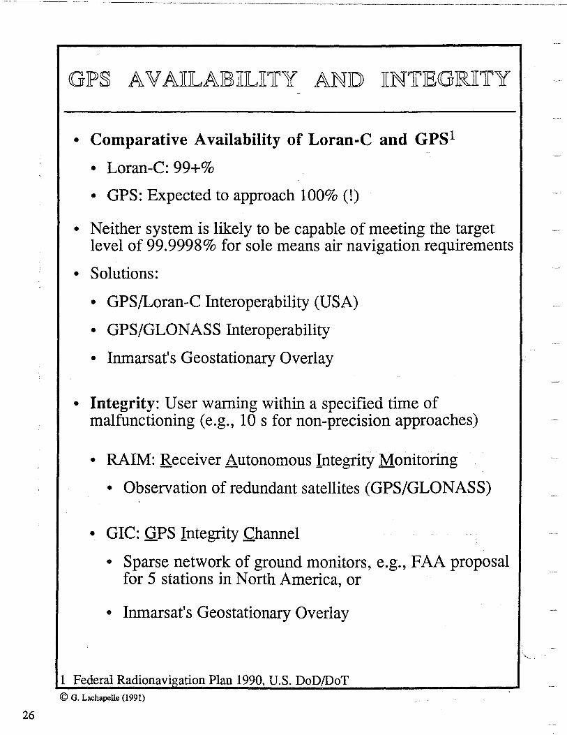
GIP§ AV AJIILAIB3JIILJI1fY ANJD JIN1rIEGRJI1rY
• Comparative Availability of Loran-C and GPS1
• Loran-C: 99+%
• GPS: Expected to approach 100% (!)
• Neither system is likely to be capable of meeting the target level of 99.9998% for sole means air navigation requirements
• Solutions:
• GPS/Loran-C Interoperability (USA)
• GPS/GLONASS Interoperability
• Inmarsat's Geostationary Overlay
• Integrity: User warning within a specified time of malfunctioning (e.g., 10 s for non-precision approaches)
• RAIM: Receiver Autonomous Integrity Monitoring
• Observation of redundant satellites (GPS/GLONASS) '
• GIC: GPS Integrity Channel
• Sparse network of ground monitors, e.g., FAA proposal for 5 stations in North America, or
• Inmarsat's Geostationary Overlay
1 Federal Radionavigation Plan 1990, U.S. DoD/DoT © G. Lachapelle ( 1991)
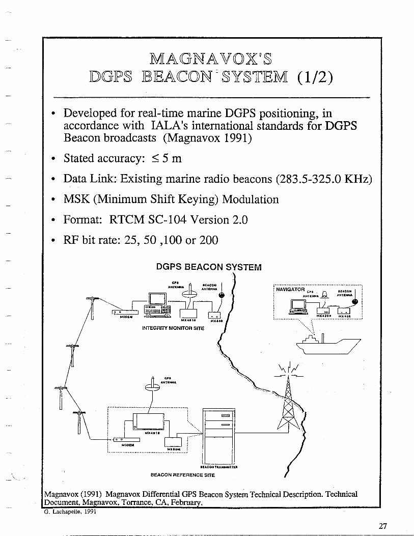
MAGNAVOXV§ ID>GIPS 183IEA<CON = SYSTIEM (1/2)
• Developed for real-time marine DGPS positioning, in accordance with IALA's international standards for DGPS Beacon broadcasts (Magnavox 1991)
• Stated accuracy: < 5 m
• Data Link: Existing marine radio beacons (283.5-325.0 KHz)
• MSK (Minimum Shift Keying) Modulation
• Format: RTCM SC-104 Version 2.0
• RF bit rate: 25, 50 , 100 or 200
DGPS BEACON SYSTEM
INTEGRITY MONITOR SITE
. ~~!" ~ CJ'S e9 AHTINHA ·~---.. <. ~·· . . -.__.
·--.. .............. .... ·~
·.,. ,., i:;:::::===:::;::i
............................................................................
= MX .. 811 ...
... t------i
MOO&M MXIOM
IEACOH TA~TTlll
BEACON REFERENCE SITE
Magnavox (1991) Magnavox Differential OPS Beacon System Technical Description. Technical Document, Ma avox, Torrance, CA, Febru G. Lachapelle, 1991
27

28
MAGNAVOXV§ JDGJP§ IB3IEACON §Y§1flEM (2/2)
• SYSTEM COMPONENTS AND CHARACTERISTICS:
[1] Differential GPS Reference Station:
• MX 4818 all-in-view receiver [Sharpe, 1989] • RTCM SC-104 standards for differential GPS service • MX-50M DGPS Beacon Modulator (MSK), 500 Hz steps • Modem for remote control of system
[2] Navigator:
• MX 4200D or MX 200 6-channel GPS receiver • MX-50R Beacon Receiver • MX4200D Control and Display PC (if MX4200D is used)
[3] Integrity Monitor (known station):
• MX 4810 12-channel GPS receiver • MX-50R Beacon Receiver • Integrity monitor PC • Modem for remote control
• Minimum Shift Keying
Special case of Frequency Shift Keying (FSK) where spectral density of signal is concentrated in a relatively narrow bandwidth [avoids interfering with the use of the direction finders]
Sharpe, R.T. (1989) The Magnavox 4818 All-in-view Differential GPS Reference Station: Descri ti.on and Test Results. NAV89 Conference, R.l.N., London, Oct 1989
G. Lachapelle, 1991

4!-~ k~J!.1 COM~ l\T '::::;· -»ti
Maritime Services
DCGJPS SJERVJICIE
DIFFERENTIAL GLOBAL POSITIONING SERVICE As the U.S. Deparunem of Defense's NA VST AR Global Positioning System moves closer to full implementation,
commercial and government users seek effective means to improve the data received from this satellite constellation. Long considered a desirable medium for delivery of differential data, the lNMARSAT global satellite system is
available for a Differential GPS service using techniques developed by COMSAT. the leader in mobile satellite communications.
As 24-hour global 2-D coverage becomes a reality, so does the feasibility of receiving data corrections in RTCM SC104 format, broadcast around the clock to any location around the world.
The DOD decision to replace a number of existing navigation systems with a 21 primary satellite constellation has been viewed as a significant improvement in navigation. has been embraced by the user community. and has been supported as the principle future system in the Federal Radionavigation Plan. There arc actually 24 satellites planned to be placed in orbit with four satellites in each of six 55° inclined orbit planes.
The variety of GPS receivers produced by an increasing numberof manufacturers has stcadil y decreased the price of end-user equipment.
DOD commitment to the system has been reinforced by award of the Block II Replacement Satellites contract and a series of launch successes has enabled the system to gain user acceptance. Many users, however, require even more precise positioning data than achievable through the system and recognize the need to broadcast correction data and to couple the use of the service with a global communications system.
COMSA T'S DIFFERENTIAL GPS SERVICE
COMSAT Mobile Communications has configured its Differential GPS service to operate with the INMARSAT A ship earth station which will receive continuous data in a broadcast mode on a predesignated frequency using RTCM SCI 04 format.
Initially, a single reference station located on the Gulf of
Mexico area will be used to • . f transmit a clear signal at 2400 bps • · • •• with one-half rate error encoding • • • (User rate of 1200 bps.). Late in 1990, data from several reference stations will be broadcast to the Atlantic Ocean Region- West and data will be encrypted.
COMSAT has dc!veloped a modification to the INMARSAT Standard A ship earth station which will enable it to receive the Differential GPS broadcast while retaining all of the normal communications capability of the ship earth station.
Reference sites can also be established to meet specific customer requircmenL~ in remote areas. Additional ocean areas will be served as market requirements develop.
COMSAT's Differential GPS service will be sold to users on a subscription basis, with volume discounts available.
© G. Lachapelle (1991)
29


FUNDAMENTALS OF LORAN-C
© G. Lachapelle (1991)
G. Lachapelle
The University of Calgary
Department of Surveying Engineering 2500 University Dr., N.W.
Calgary, Alberta Canada, TIN 1 N4
Tel: [403] 220-7104 Fax: 284-1980
Navtech Seminars, Inc.


<CON1rJEN1f S
• Historical and Concepts
• Accuracies and Dilution Of Precision (DOP)
• Geometry of Hyperbolic Positioning
• Signal Structure and Propagation
• Amplitude Modulation • Pulse Measurement • Envelope-to-Cycle Difference (ECD) • Skywave Discrimination • Pulse Transmission • Area Monitors
• Propagation Effects
• Phase Factors • Refractivity • Conductivity • Topographic and Altitude Effects •RF Noise
• Coverage
• Loran-C versus GPS
© G. Lachapelle/The University of Calgary (1991) 1
2
D
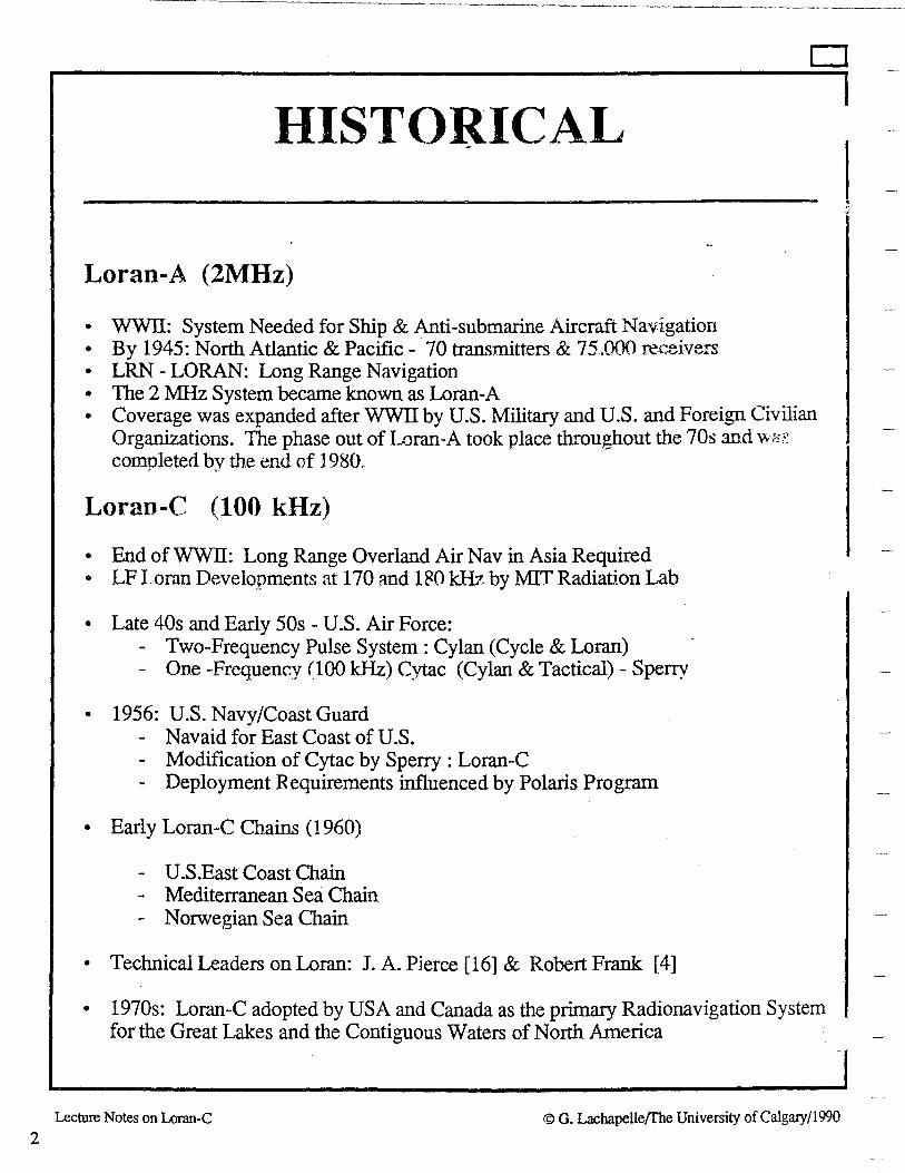
HISTORICAL
Loran-A (2MHz)
• WWII: System Needed for Ship & Anti-submarine Aircraft Navigation • By 1945: North Atlantic & Pacific - 70 transmitters & 75.000 receivers • LRN -LORAN: Long Range Navigation • The 2 :MHz System became known as Loran-A • Coverage was expanded after WWII by U.S. Military and U.S. and Foreign Civilian
Organizations. The phase out of L')ran-A took place throughout the 70s and v-.s~: completed by the end of 1980.
Loran-C (100 kHz)
• End of WWII: Long Range Overland Air Nav in Asia Required • LF I.oran Developments at 170 and 180 kHz by MIT Radiation Lab
• Late 40s and Early 50s - U.S. Air Force: - Two-Frequency Pulse System: Cylan (Cycle & Loran) - One -Frequency (1()() kHz) Cytac (Cylan & Tactical) - Sperry
• 1956: U.S. Navy/Coast Guard Navaid for East Coast of U.S.
- Modification of Cytac by Sperry : Loran-C - Deployment Requirements influenced by Polaris Program
• Early Loran-C Chains (1960)
- U.S.East Coast Chain - Mediterranean Sea Chain
Norwegian Sea Chain
• Technical Leaders on Loran: J. A. Pierce [16] & Robert Frank (4]
• 1970s: Loran-C adopted by USA and Canada as the primary Radionavigation System for the Great Lakes and the Contiguous Waters of North America
Lecture Notes on Loran-C © G. Lachapelle{The University of Calgary/1990

I
LORAN-C USERS
•MARINE • Since Mid 70's
• N.A. ~oran-C Chains Operated by USCG and CCG
• Primary Navaid in Great Lakes and Contiguous Waters of North America
• AIR
• U.S. NAS - Supplemental Navaid for en Route Navigation and terminal and Non-Precision Approaches
• Interoperable GPS/Loran-C being Investigated for sole means air Navigation
• TERRESTRIAL • Newest User Group
• Expected to be in the Millions by 2000
• Mostly Road Users ( e.g, Dispatch Systems, Fleet Monitoring)
• Integrated Navigation + Communication Functions
©Lachapelle & Townsend/En Route Coverage Validation and Calibration of Loran-C with GPS ION GPS 90
3

4
D
CONCEPTS
• 100 kHz; Amplitude modulated
• Bandwidth - 90 to 110 kHz
• Pulsed System - Time Sharing, & Ambiguity Resolution
• Sky Wave Discrimination: 3rd cycle of Ground Wave Pulse
• Ground & Sky Wave: Navigation normally using Ground Wave; Sky Wave is less Accurate but results in Longer Range
• MODE: Mostly Hyperbolic; Sometimes Circular - Navigation on two Transmitters Using a Synchronized Atomic Time & Frequency Standard
• Range of Transmitter= f{Power of Transmitter, Ground Conductivity, Ambiant Noise}; At Sea - 1,000 n.m.
• Accuracy= f{geometry, receiver, conductivity, topography}
• Marine Navigation Coverage Stated when Accuracy > 500m (2drms)
• Repeatability 50 m; Marine Differential Loran - 10 to 20m.
• Typical Chain: 1 Master + 2-4 Secondaries
• Transmitters Separated by Distances of Several Hundred n.m.
• Coastal Chains Initially Layed out to Maximize Coverage at Sea {
Lecture Notes on Loran-C © G. Lachapelle/The University of Calgary/1990

ACCURACY~MEASURES
• ACCURACY: Degree of closeness of an estimate to its true (but unknown) value
• PRECISION: Degree of closeness of observations to their means (1-D Case - standard deviation - 1 cr)
• In Practice, Accuracy and Precision are often assumed to be the same
• PREDICTABLE ACCURACY: Accuracy of a position with respect to a reference coordinate system. Equivalent to Absolute Accuracy
• REPEATABLE ACCURACY: Accuracy with which one can return to a position having coordinates which have been measured previously with same system
• RELATIVE ACCURACY: Accuracy of a user's position with respect to that of another user of the same navigation system; or accuracy of a user's position with respect to position in recent past.
• RESOLUTION: Measure of the degree of performance capability that a system can achieve.
G. Lachapelle March 1990
5
D
I
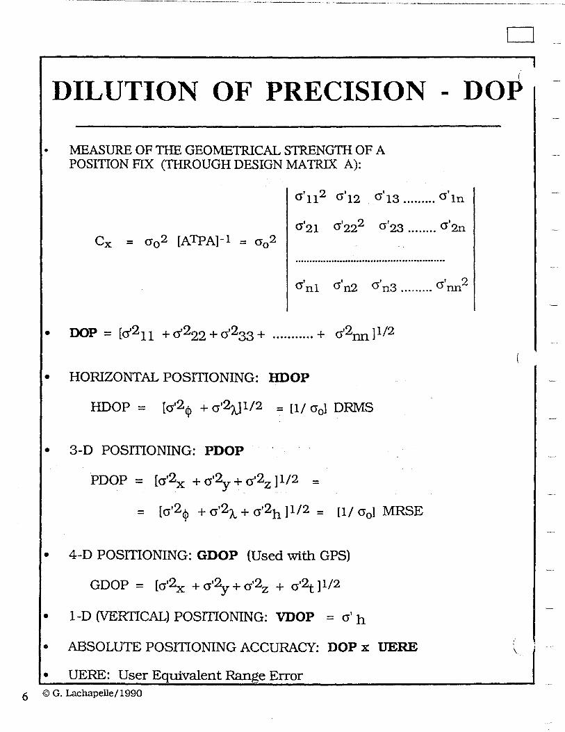
DILUTION OF PRECISION - DOP
• MEASURE OF THE GEOMETRICAL STRENGTH OF A POSffiON FIX (THROUGH DESIGN MATRIX A):
<>'112 <>'12 a' <>' 13 ......... ln
<>'21 cr'222 <>' <>' 23 ........ 2n
.....................................................
' a' a' a' 2 <J nl n2 n3 ... . . . . . . nn
• OOn - [ 12 -'2 12 12 ]1/2 'A - (J 11 + U 22 + (J 33 + •" ••""" + (J nil
• HORIZONTAL POSIDONING: HDOP
HDOP = [<>'2<t> + a'2tJ 1/2 = [l/ cr0 ] DRMS
• 3-D POSITIONING: PDOP
PDOP = [a'2x + <>'2y + a'2z] 1/2 =
= [a'2<t> + a'2A. + (J'2h] 1/2 = [l/ a0 ] MRSE
• 4-D POSITIONING: GDOP (Used with GPS)
GDOP = [<>'2x + <>'2y + a'2z + a'2t ]1/2
• 1-D (VERTICAL) POSIDONING: VDOP = a' h
• ABSOLUTE POSITTONING ACCURACY: DOP x UERE
• UERE: User Equivalent Range Error 6 ©G.Lachapelle/1990
( \

D
HYPERBOLI-c MODE - I
· LINES OF POSITION (LOP)
• Locus of Points Along a Line of:
• Constant Distances from a Reference Station: Concentric Circular Lines ;... Distance Measurements to an Unknown Point
• Constant Angles: Eccentric Circles - Angle Measurements from an unknown point to two known points
• Constant Azimuth: Straight Line - Direction Measurements between a known and an unknown point
• Constant Range Differences (or Time Differences): Hyperbola -Distance differences measured at unknown point from two known points (e.g., two Loran-C Transmitters). -
• INTERSECTION OF AT LEAST 2 LOP'S:
• Horizontal Position Fix
• e.g., 2 Circles, 2 Hyperbolae (Usually trivial ambiguity)
Lecture Notes on Loran-C © G. Lachapelle(fhe University of Calgary/1990
7

8
D
HYPERBOLIC MODE - II
· HYPERBOLIC MODE:
• Distance or Time Differences (TD's) are Measured Using Phase Comparison (e.g., Omega) or Pulsed Signals (e.g., Loran-C)
• Hyperbola: Line of Constant Distance Difference (from two Known Stations)
• At Least Two LOP's are Required for a Horizontal Position Fix
• At Least Three Transmitters are Required to Measure two LOP's
• LANE: Greatest Possible Phase Difference Between Two Signa\ i.e., 180°
• LANE WIDTH (On Baseline Master-Secondary):
• L' w = /..,/2 {Phase Comparison, e.g., Decca} • L'w = t(c/2) {Pulsed Sytem, e.g., Loran-C; tis the timing unit}
• L'w : if t is selected as 1 µs, L'w = 150 m
• The Lane Width Changes due to the Divergence of Hyperbolae.
• Lat Point P (See Figure next Viewgraph)
• Lw = L'w cosec p/2 for M-GS Pair
• ~w = L'w cosec 'V/2 for M-RS Pair
• co sec 'V /2 is sometimes called the lane expansion factor
Lecture Notes on Loran-C © G. Lachapelle/The University of Calgary/1990

D
HYPERBOLIC MODE - III
• Lane Width
Lw = L'w cosec( p/2) t
• p and 'V are the angles at the unknown point P subtended by the baselines joining the Master and the Secondary Stations
• e = (p + 'tf)/2' where e is the angle between the intersecting hyperbolae at P
• The CW or Pulsed Transmission at the Two Secondaries are Controlled by the Master Station
• Loran-C Hyperbolae are Printed on Canadian Charts in Areas of Loran-C Coverage
• The Intersection of at least two Hyperbolae results in a 2D (Horizontal) Position Fix
Lecture Notes on Loran-C © G. Lachapelle{fhe University of Calgary/ 1990
9

10
D
GEOMETRY OF HYPERBOLIC POSITIONING
Lecture Notes on Loran-C © G. Lachapelle/The University of Calgary/1990

HYPERBOLIC MODE - IV
• DIRECT 2D.SOLUTION WITH OR WITHOUT REDUNDANCIES (2 or more Hyperbolae) x = - (ATcL-l A )-1 ATcL-l L
Cx = cr02 (ATCL-l A )-1
CL being the Covariance Matrix of the Observations L (TD's in units of length), and cr0 2, the a priori error variance
D
• The drms or HDOP (drms/cr0 ) can be calculated directly using the
Covariance Matrix Cx for any Hyperbolic Configuration, e.g., 1
M + 2 S, 1 M + 3 S, etc.
• A typical Error Propagation Pattern for an Isotropic Chain of 1 M + 3S is shown below [5]. There are redundant measurements { 3 TD's for 2 Horizontal Coordinates} and the above Least-squares Formulae are applied. {Exercise: What was the cr0 2 used?}
Lecture Notes on Loran-C
I I lOOOkm
© G. Lachapelle{fhe University ofCalgary/1990
11

12
HYPERBOLIC MODE - V
• DIRECT DRMS FORMULA FOR THE HYPERBOLIC CASE OF 1 M + 2 S (No redundancy) [1]
DRMS = Cosec 0 [cr2R + cr20 + kRo crR cr0 cos 8]1/2
where kRG is the correlation coeffficient between the measurements of the R and G phase or time differences.
• crR and cr0 at the point P are given by
crR = cr'R cosec p/2 cra = cr'o cosec 'lf /2
cr'R and cr'0 being the corresponding values on the M-R and M-G b~selines respectively. The cosec term accounts for lane expansion.
• Maximum Correlation {kRo = 1} is generally assumed when deriving the DRMS or HDOP. This will yield the largest, i.e., most conservative, values.
D
EXAMPLE: The Loran-C TD's are measured with an accuracy of 0.1 µs, i.e., 30 m. This value will be used directly, together with associated covariances to derive Cx as described earlier. If the above DRMS formula is used directly, cr' on the baseline will b~ { 0.1 µs x ( c/2)} , i.e., 15 m, Loran-C being a pulsed system.
Lecture Notes on Loran-C © G. Lachapelle{fhe University of Calgary/1990

D
HYPERBOLIC MODE - VI
• ADV ANT AGES OF THE HYPERBOLIC MODE:
• Unlimited Number of Users
• A relatively low accuracy /low cost quartz clock with a short term stability (over 1 s) is sufficient to measure the TD's.
• In the Case of Loran-C: Low cost User Equipment ( <$1,000)
• OTHER MODES
• CIRCULAR
• Ranges or Pseudo-ranges measured directly
• Two Intersecting Circles (LOP's) for a 2D Solution
• Better Geometry than Hyperbolic; No Lane Expansion
• Range/Range Mode: Receiver interrogates Sequentially at least two Shore Transmitters - Limited Number of Users
• Rho-rho Mode: Receiver requires Atomic Time and Frequency Standard if only two Transmitters are available
• Pseudo-Ranging Mode: Same as rho-rho but no precise Clock. High grade Loran-C Receiver - May acquire Signals from several Chains simultaneously.
• RHO-THETA '
• Ranges and Azimuth are Measured.
Lecture Notes on Loran-C © G. Lachapelle!The University of Calgary/1990
13

14
D
CHAIN CONFIGURATION i
• Ideal 1 M + 3 S Isotropic Hyperbolic Configurati9n
• Typical Chain Configuration to Optimize Marine Coverage: (Partial) Canadian East Coast Chain
Lecture Notes on Loran-C © G. Lachapelle{fhe University of Calgary/1990
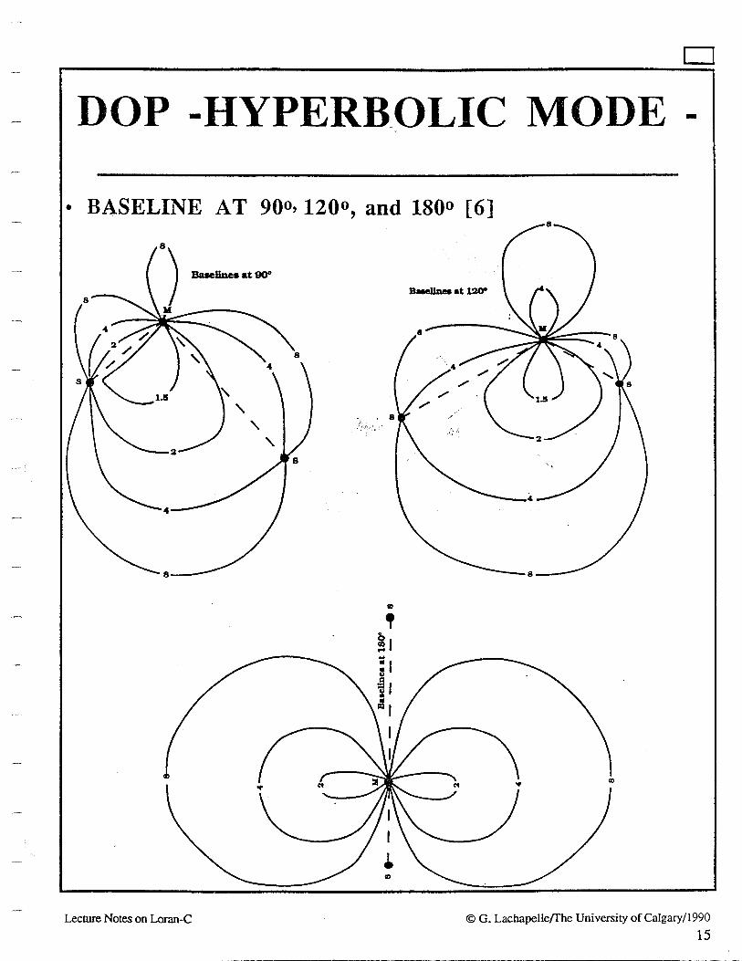
D
DOP -HYPERB_OLIC MODE -• BASELINE AT 900, 1200, and lSOo [6]
8
Q)
Lecture Notes on Loran-C © G. Lachapelle/The University of Calgary/1990
15

16
CJ
PROPAGATION AT 100 kHz
• D- or E-Layer of Ionosphere acts as an almost perfect reflecting surface
• Two Waves
• Ground Wave: Precise Travel Time along Earth's Surface; Used for Positioning; Travel Time affected by refractivity, ground conductivity (and permittivity), and topography
• Bending of the Ground Wave: diffraction and absorption into the ground (or water)
• Sky Wave: May Interfere with Ground Wave; Intensity greater at Nightime (due to D-layer of Ionosphere)
• Large antennae at Transmitters for Efficient Transmission (A..= 3,000 m); Vertical Polarization
(Man Made Noise is also Mostly Vertically Polarized)
Lecture Notes on Loran-C © G. Lachapelle{fhe University of Calgary/1990

\
D
GROUND & _SKY WAVE
• Intensities of Ground and Sky Waves [2]
0 500 1000 1500 2000 2500 3000 3500 4000 4500
Distance (Km)
• Sky Wave Delay [2] 400 ----------------..... --------...-----------------!
320
~ ~ 'i) 240 0 v ~ :::: £ 160 (/)
0 '---------------------------------------------0 250 500 750 1000 1250 Distance (Km)
Lecture Notes on Loran-C © G. Lachapelle{fhe University of Calgary/1990
17

18
D
SIGNAL STRUCTURE I
• LORAN-C PULSE
• Carrier at 100 kHz (A= 3,000 m, Tcycle = 1/f = 10 µs) • Tpulse = 250 µs (1 pulse - 25 cycles)
• Pulse is quickly raising in Amplitude to allow Cycle Measurement at the Beginning of the Ground Wave Pulse, before the Sky Wave Pulse reaches the Receiver and Interferes with the Ground Wave Pulse
• Coarse Measurement is Made on Pulse Envelope (Ambiguity Resolution) and Cycle Matching on 3rd Cycle (6th Zero Crossing) of the Carrier (30 µs from start of Pulse)
• 3rd Cycle lndentification [3]: Front Edge Location, Phase Reversal, Linear Envelope Processing
• Envelope+ Cycle Matching= Total TD (Time Difference)
. •.>Accuracy of Cycle Matching: Receiver and Noise Dependent; 0.01 to 0.1 µs { 0.01 µs = 0.001 cycle since Tcycle = 1/f = ( 10 µs; 0.001 cycle= 3 m}.
Lecture Notes on Loran-C © G. Lachapelle{The University of Calgary/1990

SIGNAL STRUCTURE II
• PULSE LEADING EDGE SPECIFICATIONS
Standard 7 Measu~ Point
5
~ 3
" ' ~ I ~~ v 21 v I 41
9
I I sl I I I I I I al I I I I I I I 11 I I
. . . . 10 20 30 40 50 60 70
Time of Zero CrosslnJI: (µs)
' I
i(t) ... Loran-C Waveform Intensity (amperes} • i(t) = 0 [t < 't]
D
• i(t) =A (t - -r)2 exp{[-2(t- -r)]/65} sin (0.2rct +PC) [-r <t< 65+-r)]
A ... Normalization constant (amperes) related to the peak antenna current magnitude
t... time in µs -r... Envelope-to-Cycle Difference (ECD) PC .. Phase code Parameter in radians [O and TC for + and - phase
code respectively]
• i(t) = 0 at t (µs) = 0, 5, 10, 15, etc /
f ( • " 1exp{ [-2(t - -r)]/65} ... Shape of Amplitude Modulating Envelope • sin (0.2rct +PC) ... Carrier (sinusoid) wave at 100 kHz
{tin µs: sin (rot+ PC) =sin (2rcft +PC) When tis ins} Lecture Notes on Loran-C © G. Lachapelle(The University of Calgary/1990
19

20
D
PULSE TRANSMISSION I
• Pulses are transmitted in Groups of 9 (at a Master) or 8 (at a Secondary) to allow the Receiver to make more Measurements for a Position Fix.
• The 9th Pulse transmitted from a Master can be switched on/off and is ·used for user's warning
• STRUCTURE OF A PULSE GROUP [3]
• 1,000 µs or 2,000 µs between successive pulses 1000 µs 2000 µs
300 µs (approximate)
• Master and Secondary Transmitters are precisely Time and Phase synchronized using cesium Time and Frequency Standards
• Secondary Stations are transmitting after the Master with Unique Delays for their Identification
• Delays sufficiently long to ensure the signals from all stations are received in the same sequence in area of Chain Coverage
Io ooo • Delays vary between 10,000 and~ µs
Lecture Notes on Loran-C © G. Lachapelle{fhe University of Calgary/1990
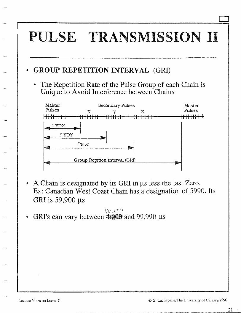
PULSE TRANSMISSION II
• GROUP REPETITION INTERVAL (GRI)
• The Repetition Rate of the Pulse Group of each Chain is Unique to A void Interference between Chains
Master Pulses
11111111 I
Secondary Pulses x y z
11111111 11111111 11111111
EIDZ
Group Repitlon Interval (GRI)
Master Pulses
1111111 I I
• A Chain is designated by its GRI in µs less the last Zero. Ex: Canadian West Coast Chain has a designation of 5990. Its GRI is 59 ,900 µs
!(() 0
• GRI's can vary between 4- and 99,990 µs
D
Lecture Notes on Loran-C © G. Lachapelle(The University of Calgary/1990
21

22
D
PULSE TRANSMISSION III
• SKYWAVE INTERFERENCE ON ADJACENT -PULSES
• Interval between successive pulses is 1,000 µs
• A Skywave delayed by more than 1,000 µs will therefore interfere with the next Pulse
• Countermeasure: Phase is coded (180° shift) according to two Sequences which are used alternatively as shown below [3]:
Master Each Secondary
Allllllll I 11111111 ++--+-+- + +++++--+
Bllllllll I 11111111 +--+++++ - +-+-++--
Each transmitter alternates the A and B sequences.
= + = \ ~
Lecture Notes on Loran-C © G. Lachapelle/The University of Calgary/1990
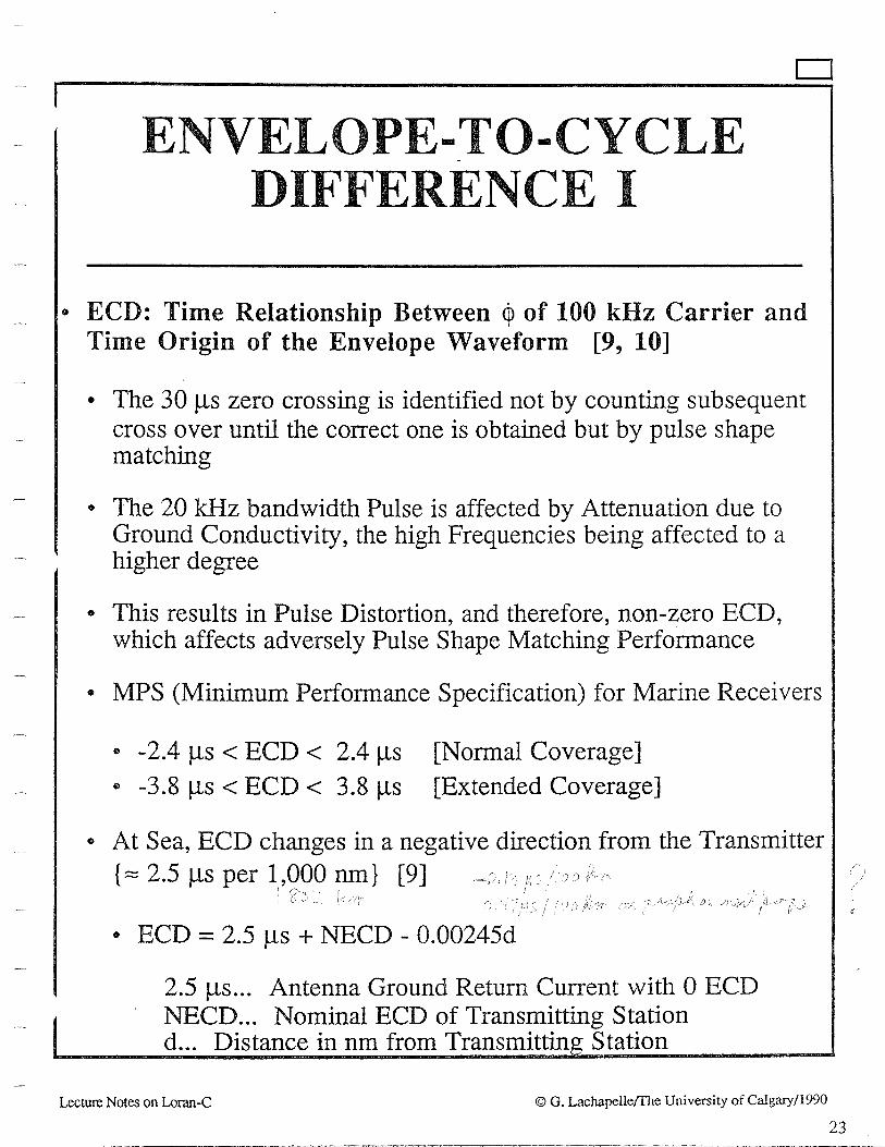
D
ENVELOPE-_TO-CYCLE DIFFERENCE I
• ECD: Time Relationship Between ~ of 100 kHz Carrier and Time Origin of the Envelope Waveform [9, 10]
• The 30 µs zero crossing is identified not by counting subsequent cross over until the correct one is obtained but by pulse shape matching
• The 20 kHz bandwidth Pulse is affected by Attenuation due to Ground Conductivity, the high Frequencies being affected to a higher degree
• This results in Pulse Distortion, and therefore, non-zero ECD, which affects adversely Pulse Shape Matching Performance
• MPS (Minimum Performance Specification) for Marine Receivers
• -2.4 µs < ECD < 2.4 µs [Normal Coverage] • -3.8 µs < ECD < 3.8 µs [Extended Coverage]
• At Sea, ECD changes in a negative direction from the Transmitter {:::::2.5µsperl,000nm} [9] - 1)r / >
I ~- ; i ' ( ;1: ; .J: ,. ( . '.} '!
• ECD = 2.5 µs + NECD - 0.00245d
2.5 µs... Antenna Ground Return Current with 0 ECD NECD... Nominal ECD of Transmitting Station d ... Distance in nm from Transmittin Station
Lecture Notes on Loran-C © G. Lachapelle(fhe University of Calgary/1990
23

24
ENVELOPE-TO-CYCLE DIFFERENCE II
• ECD ON LAND
• f (Conductivity) [10] • Can be nearly four times as high as at sea
1.6 \
\ \ ~
~ ~~ --
0.4.
o.o 0.0005 0.001 0.005 0.01 0.06 0.1 0.5 1 5
Coodnctivity in mho/m
D
• Transmitters that are inland are offset by a nominal value (NECD) to limit ECD to + 2.5 µs in Area of Coverage
• e.g., Canadian West Coast Chain (5990):
NECD at M (Williams Lake) is 1 µs NECD at Y (George) is 0.5 µs NECD at X and Y is 0.0 µs
• EFFECT OF TOPOGRAPHY ON ECD { 10]
• ECD can go Positive in Sharp Terrain and return to expected value some 50 to 100 nm from the Mountains
Lecture Notes on Loran-C © G. Lachapelle{fhe University of Calgary/1990

GROUND/SKY WA VE INTERFERENCE I
• Low Ionosphere & Large Distance from Transmitter: Sky Wave may arrive before the 30 µs point of the Ground Wave Resulting Interference:
Propagation Over All-Sea Path
40km
0 1--~~-+-~~~~~~.j..._~~-+-~~---+~~~-+-~~-o 250 500 750 1000 1250 1500 1750
Distance (Km)
D
Lecture Notes on Loran-C © G. Lachapelle(The University of Calgary/1990
25

26
D
INTERFERENCE II
• Resulting Interference:
v ~
• Cycle Matching may be made after the 3rd Cycle of the Pulse, when more Power is available. The 7th Cycle is sometimes used. The sky wave is then used. This can extend the Range by several hundred nm. The accuracy degrades accordingly
• NOISE INTERFERENCE:
• Bandwidth of Pulse: 20 kHz - Subject to Interference, e.g., atmospheric and/or man-made
• "Notch Filters" are used to block out Interference at specific frequencies within 90 - 110 kHz
• , If too many filters are used, the Pulse will be distorted and Lower Accuracy will result
Lecture Notes on Loran-C © G. Lachapelle/The University of Calgary/1990

AREA MONITORS
• Located in Coverage Area • Typically 2 - 3 per Chain
• FUNCTIONS
• Continuous Sampling of specified Parameters, e.g., TD, ECD • Corrections are made at Transmitters if and when necessary to
ensure the Parameters are maintained within certain tolerances
• CONSEQUENCE: High Repeatable Accuracy in Areas where Monitors are located
D
• Location of Area Monitors is usually optimized for Ocean Coverage • Example: Chain 5990: 3 Area Monitors along the Coast
Lecture Notes on Loran-C
'"'°11>- WRAN-C Accuracy Contours
© G. Lachapelle(fhe University of Calgary/1990
27

D
PHASE FACTORS
• PHASE FACTORS
• Primary (Factor): Correction for propagation through atmosphere as opposed to free space
• Secondary (SF): Additional delay (µs) when the signal is assumed to propagate over an all sea-water (a= 5 S m-1) path
• Additional Secondary (ASF): Additional delay (µs) by propagation over terrain
• SF+ ASF [2]:
(j) ..=!-
12 ........................... _,_ ............... ..._,. ............ ...._ ______________ .......... ......,... ............... -v-........ ----..
I-< 0 ...., ()
~ 10t--------+i------+------.,._ ____ ....., ______ p......~ ......... ---+-~~-i 11) (/) ('j
..c: 0..
fa' 8 1-----1----+----+----;...i:;;....-~~=r--t-----1 "O c: 0 () 11)
w. 61-------i------+--......,~..J-.._d:;.._-i-......... ----~--~~-----I '@ i:: 0 ~ .:c; ~ 41-------+-~--"'4----~~-----1-------+----~,....~----t (/)
::l 0::
~ 2~~~~~----+-------~---~~.....s-..... .......... +--................... -t-.................... ~ c: 0 () <l.l w 0------------......,.----.......... ...1..-----_._ _______ "--___________ __
0 250 500 750 1000 1250 1500 1750
Distance (Km)
28 Lecture Notes on Loran-C © G. Lachapelle/The University of Calgary/1990

D
REFRACTIVITY I
• DEFINITION
• Refractive Index n
• n = Velocity in vacuo/velocity in medium = cvf Cm
• n > 1 in Troposphere
• N = (n - 1) 106 = Refractivity
• At RF, Troposphere is non-dispersive and N has the same effect on all RF
• CALCULATION
• N = f {P, T, e}
• P ... Total atm Pressure (millibars)
• e . . . Partial Pressure of Water Va pour (millibars)
• T ... Dry Temperature (Kelvins)
• Formulae: Essen's, Essen-Froome, and Smith-Weintraub
• Smith-Weintraub:
N = (77.6{f) {P + 4.81 x I03(e[f2)}
• Average N on Earth's Surface: 320
Lecture Notes on Loran-C © G. Lachapelle/The University of Calgary/1990 29

C 0 ND U C~TIVITY
• GROUND WAVE PROPAGATION AFFECTED BY
(1) Conductivity (a)
a = lip {p ... resistivity in Q.m}
Q-1 = mho = siemens
a is in mho m-1 or siemens m-1
(2) Permittivity (Kor£)
Relative Permittivity Kr (unitless) {Ability of a material to sustain an electric flux}
Relative Permittivity = Dielectric Constant Ko (vacuo) 8.854 x 10⁻¹² C2/(N.m2) {SI}
Absolute Permittivity K = Kr . Ko
• (2) is negligible except when (1) is relatively very poor
• Propagation= f(cr, Kr): Sommerfeld & Norton [13]
Surface Relative Permittivity( Kr) Conductivity (siemens m-1)
Sea Water Fresh Water Moist Soil Dry Soil Sea Ice [11,12]
80 80 15-20 4
5. 0.005 0.005 - 0.01 0.001 - 0.01 0.013
D
30 Lecture Notes on Loran-C © G. Lachapelleffhe University of Calgary/1990

D
EFFECT OF CONDUCTIVITY
• EFFECT OF CONDUCTIVITY
• EM Energy Absorbed into the Ground
• Bending of the Wave Front (Secondary Phase Lag)
• Bending decreases up to an altitude of SA:
• Lag Increases with Distance from Transmitter and Decreases with Increasing Conductivity
WAVE FRONT
/
• Energy Penetration Depth at 10 kHz, 1 OOkHz, and 1 MHz [ 15]
Material
Sea Water Good Ground Poor Ground
Lecture Notes on Loran-C
cr(mS m-1)
5000 30 3
lOkHz
2.Sm 29.0 92.0
lOOkHz
0.7m 9.2
29.0
1 MHz
0.25m 2.9 9.2
© G. Lachapelle(The University of Calgary/1990 31

D
a IN NORTH AMERICA
• Conductivity in North America [5]
.•
·:.
1 /
/ I / I
I I I
I
I ·' I
I Efl•ctW• Vl..f COA4W4ttwf'IY
<1,·('"fHI'••
© 1 x 10 ..
® 3 x 10·•
0 1 " 10·•
© 3 x 10·•
' © 1 x 10·>
@ 3 " 10·>
0 1 x 10 • 2
@ 3 x 10·•
© 1 x 10· 1
! @ " ... , ......... I
~~@ -J ......... ........ ..... , ... ,
==-~~ .. •.!.u.:-.!-u...
32 Lecture Notes on Loran-C G. Lachapelle{fhe University of Calgary/1990

GROUND CONDUCTIVITY
• Secondary Phase Lag - Varies with Soil
• Practically Constant in Time - Can be Calibrated
• Bending of the Wave Front: ......----------------.
• Attenuation of Signal Strength as a Function of Distance from Transmitter (RTAC 1987)
90
80 Transmitter Power Correction
Power (KW) dB a 160-0 +6 ....... ~ 70 .... 800 +3
~ 4-00 0 .§ ~ 60 200 -3
f 50 Propaflat;iQD fnth !1J 't:I Seawater, 5 nilio/m 'il ~ "Good" Land. 0.005 nilio/m
40
"Poor" Land, 0.002 mJJ.o/m
30 0 500 1000 1500 2000 2500
Distance, Kilometre
©Lachapelle & Townsend/En Route Coverage Validation and Calibration of Loran-C with GPS ION GPS 90 33
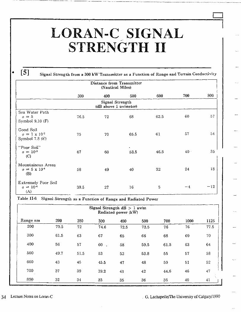
LORAN-C SIGNAL STRENGTH II
D
• [5] Signal Strength from a 30-0 kW Transmitter as a Function of Range and Terrain Conductivity
Distance from Transmitter (Nautical Miles)
300 40-0 500 600 70-0 800
Signal Strength (dB above I uv/meter)
Sea Water Path a = 5 76.5 72 68 63.5 60 57
Symbol 9,10 (F)
Good Soil a = 1 x 10"2 75 70 65.5 61 57 54
Symbol 7 .8 (E)
"Poor Soil" a = 10•3 67 60 53.5 46.5 40. 35
(Cl
Mountainous Areas a = 5 x 10"4 58 49 40 32 24 18
(B)
Extremely Poor Soil a = io-4 39.5 27 16 5 -4 -12
(A)
Table II-6 Signal Strength as a Function of Range and Radiated Power
Signal Strength dB > I uv/m Radiated power (kW)
Range nm 200 280 30-0 40-0 50-0 70-0 10-00 1125 200 70.5 72 74.6 72.5 73.5 76 76 77.5
300 61.5 63 67 65 66 68 69 70
400 56 57 60 58 59.5 61.5 63 64
500 49.7 51.5 53 53 53.8 55 57 58
600 43 45 45.5 47 48 50 51 52
700 37 39 39.2 41 42 44.6 46 47
800 32 34 33 35 36 38 40 41 I
34 Lecture Notes on Loran-C . G. Lachapelle/Ihe University of Calgary/1990

F NOISE
• Unwanted Energy Interfering with Reception and Reproduction of Wanted Signal
• Classification
• External (to the receiver) • Atmospheric • Solar (Extraterrestrial) • Cosmic (Extraterrestrial • Industrial Noise
• Internal (Created by the receiver itself) • Thermal (also called White or Agitation Noise) • Shot Noise • Transit-Time Noise • Flicker Noise • Resistance Noise
• Noise Calculation
• Noise Figure
• SNR (Signal to Noise Ratio)
G. Lachapelle/ The University of Calgary 1990 35

D
ATMOSPHERIC NOISE I
• Caused by thunderstorms, lightning bursts • Very significant in the 90 - 110 kHz frequency band • Decreases with increasing latitude • Average noise in the Loran-C band (µV m-1) derived by Lewis [5]
from CCIR world data [26]:
0 400 800
Kilometres
36 Lecture Notes on Loran-C © G. Lachapelle(fhe University of Calgary/1990
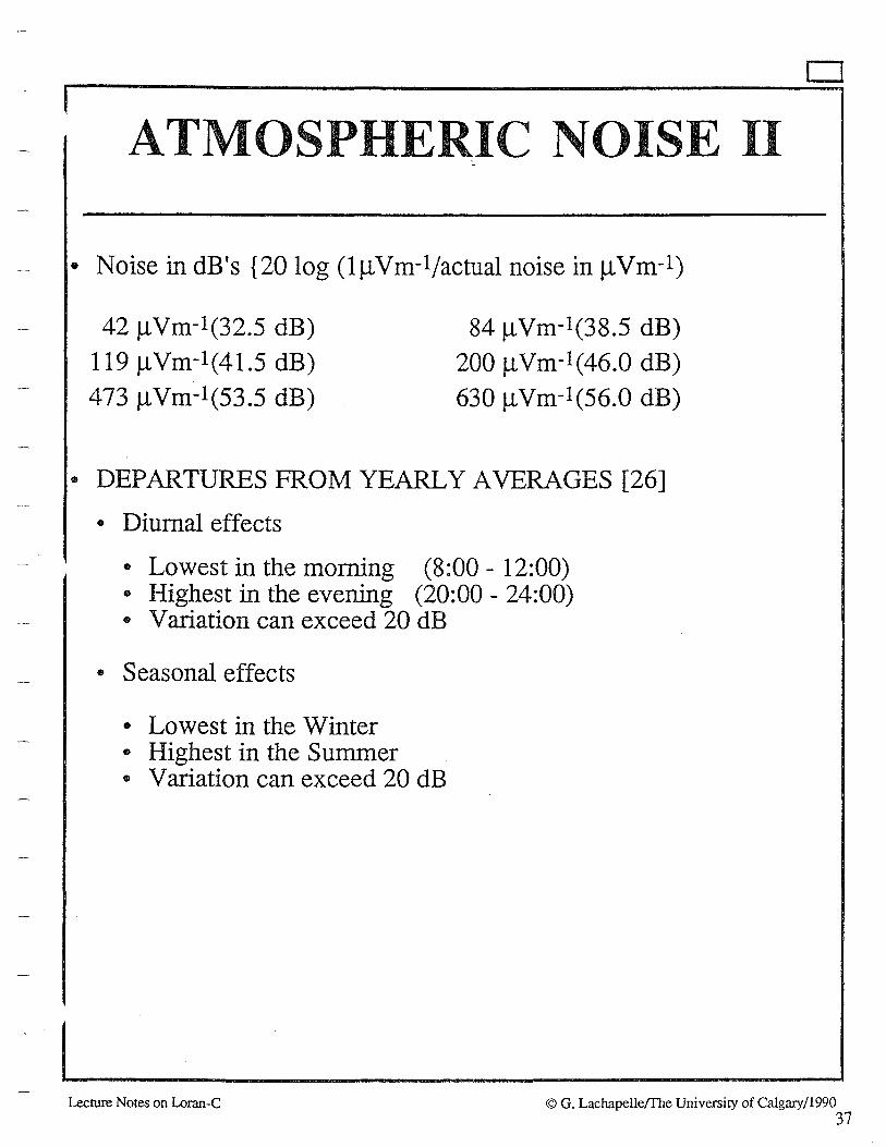
ATMOSPHE IC NOISE II
• Noise in dB's {20 log (lµVm-1/actual noise in µVm-1)
42 µVm-1(32.5 dB)
119 µVm-1(41.5 dB)
473 µVm-1(53.5 dB)
84 µ Vm-1(38.5 dB)
200 µVm-1(46.0 dB)
630 µVm-1(56.0 dB)
• DEPARTURES FROM YEARLY AVERAGES [26]
• Diurnal effects
• Lowest in the morning (8:00 - 12:00) • Highest in the evening (20:00 - 24:00) • Variation can exceed 20 dB
• Seasonal effects
• Lowest in the Winter • Highest in the Summer • Variation can exceed 20 dB
D
Lecture Notes on Loran-C © G. Lachapelle(The University of Calgary/1990 37
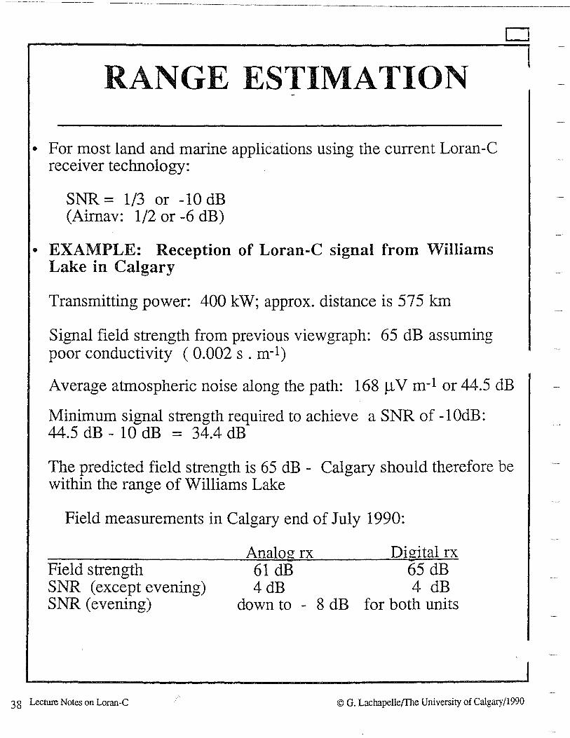
RANGE ESTIMATION
• For most land and marine applications using the current Loran-C receiver technology:
SNR = 1/3 or -10 dB (Airnav: 1/2 or -6 dB)
• EXAMPLE: Reception of Loran-C signal from Williams Lake in Calgary
Transmitting power: 400 kW; approx. distance is 575 km
Signal field strength from previous viewgraph: 65 dB assuming poor conductivity ( 0.002 s . m-1)
D
Average atmospheric noise along the path: 168 µV m-1 or 44.5 dB
Minimum signal strength required to achieve a SNR of -1 OdB: 44.5 dB - 10 dB = 34.4 dB
The predicted field strength is 65 dB - Calgary should therefore be within the range of Williams Lake
Field measurements in Calgary end of July 1990:
Field strength SNR (except evening) SNR (evening)
38 Lecture Notes on Loran-C
Analog rx 61 dB 4dB
down to - 8 dB
Digital rx 65 dB 4 dB
for both units
© G. Lachapelle{The University of Calgary/1990

NORTH AMERIC-AN COVERAGE
• Including NOCUS & SOCUS/1990-91
0 400 000 kn: I I .......
• Uncertainty in Land Coverage -NOCUS
© Lachapelle & Townsend/En Route Calibration of Loran-C with GPS
- Monitor
0 2150 l500 715<> 1000
ION GPS 90 39
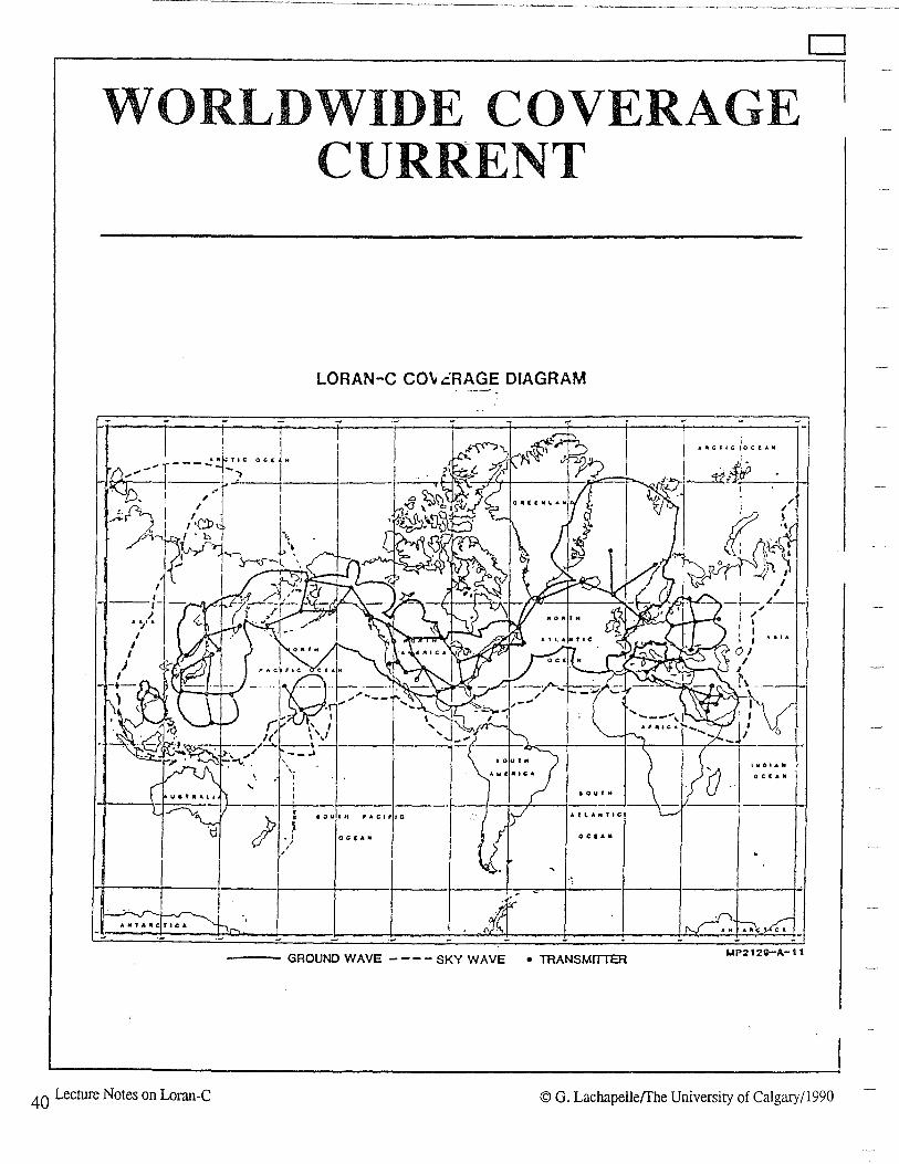
WORLDWIDE COVERAGE CURRENT
).} , ,
LORAN-C CO" cRAGE DIAGRAM
I 0 U f tf
1ourn r•c1r1c A. f LAM f IC
o.... I 0 CI AM
1 •
--- GROUND WAVE - - - - SKY WAVE • TRANSMITTER MP2120-A-11
D
40 Lecture Notes on Loran-C © G. Lachapelle{Ihe University of Calgary/1990

RJEIFIERJEN CCJE§
[1] Surveying Offshore Canada Lands for Mineral Resource Development. 3rd Edition, 1982, Surveys & Mapping Branch, Energy, Mines and Resources Canada, Ottawa
[2] Current Developments in Loran-C, R. Frank, Proc. of IEEE, Vol. 71, No. 10, 1983
[3] Marine Electronic Navigation, Appleyard, 1988, 2nd Edition, Routledge & Kegan Paul
[4] Tetley et al, Electronic Aids to Navigation, 1986, Edward Arnold
[5] RTAC, 1987, Extension of Canadian Loran-C Coverage. Technical Report,Road Transportation Association of Canada, Ottawa.
[6] Loran/GPS Interoperability. Special Tutorial, P. Enge, Navtech Seminars, Inc .. ION GPS '90, Colorado Springs, September1990
[7] Electronic Surveying and Navigation, Laurila, John Wiley & Sons, 1976
[8] Update: DLoran-C System, Matthew et al. , Proc. WGA 1987
[9] ECD Predictions for the Mid-Continent Loran-C Chains, D.S. Taggart, Proc. WGA, 1988
[10] Finally - A Practical ECD Estimating Technique, H.T. Sherman, Proc. WGA 1984
[11] Propagation Velocity of Decca Frequency Transmissions Over Sea Ice, D.H. Gray, Can. Surv. Vol 29, No. 3, 1975
[12] Beaufort Sea Loran-C Tests, Eaton et al., Can. Aeron. Joum. Vol. 28, No. 1, 1982
[13] The Theory of Loran-C Ground Wave Propagation - A Review, Samaddar, Navigation, Vol. 26, No. 3, 1979.
[14] Phase of the Low Radiofrequency Ground Wave, Johler et al., 1956, NBS Circ. 573
© G. Lachapelle{The University of Calgary (1991) 41

[15] Radiowave Propagation, Hall, IEE EM Wave Series 30, 1989
[16] An Introduction to Loran, J.A. Pierce, 1EEE Aerospace and Electronic Systems Magazine, Vol. 5, No. 10, Oct 90, pp. 16-33. {Reprint from 1946}
(17] The Radio Climatology of Canada - Tropospheric Refractivity Atlas for Canada, B. Segal & R.E. Barrington, CRC Report No. 1315-E, 1977.
(18] En Route Coverage Validation and Calibration of Loran-C with GPS. G. Lachapelle & B. Townsend, Proc. GPS'90, Inst. of Nav., Wash., D.C.
(19] A Comparative Analysis of Loran-C and GPS for Land Vehicle Navigation in Canada. G. Lachapelle & B. Townsend, Can. Joum. of Aeron., 1990, Vol. 36, No.1, pp. 29-32.
[20] Performance of Loran-C on the Canadian West Coast. G. Lachapelle, T. Speakman & B. Townsend, 1989, Proc. of 18th Ann. Techn. Symp. of WGA, pp. 135-143.
[21] Loran-C Coverage in Canada. 1986. Transport Canada Facility Eng. & Syst. Dev. Branch Aviation Group, TP 7561E
[22] Radionavigation/Location Requirements for Surface Users in Canada (Part I), 1988, Transport Canada TP9452 E.
[23] 1988 Federal Radionavigation Plan. DoD-4650.4/DoT-TSC-RSPA-88-4, Wash, D.C.
[24] Proc. of 1st GPS Canadian User & Supplier Workshop, 1988, Canada Centre for Surveying, EMR.
[25] A World Atlas of Atmospheric Radio Refractivity, Bean et al., 1966, ESSA Monograph 1, U.S. Dept of Commerce
[26] Characteristics and Applications of Atmospherics Radio Noise Data. CCIR Report No. 322-3, ITUGeneva, 1988
42 © G. Lachapelle!fhe University of Calgary (1991)

CAJLliJBJKATliON OJF JLOJRAN=C WliTJHI GP§
• ACCURACY CHARACTERISTICS OF LORAN-C
• Loran-C stability
• Atmospheric effects
• Diurnal and seasonal effects
• Topographic effects
• Altitude effects
• GPS VERSUS LORAN-C
• CALIBRATION OF LORAN-C
• Millington method
• Non-linear regression
• Use of GPS
• Gulf of Maine trials(a)
• Static and en-route calibration using LORCAL2 Cb)
(a) J.J. Pisano, P.K. Enge & P.L. Levin (1991) Using GPS to Calibrate Loran-C. IEEE Transactions on Aerospace and Electronic Systems, Vol. 27, No. 4, pp. 696 - 708
(b) G. Lachapelle and B. Townsend (1991) En-Route Coverage Validation and Calibration of Loran-C with GPS. GPS World, Volume 2, No. 3, pp. 36-41.
G. Lachapelle ( 1991)


• Example: Canadian West Coast Chain 5990 • Differences during period May - August 1989:
285
(/)
@ 280 ...... Q)
~ 275
270
120 140 160 180 200 220 240 Julian Day
Diurnal Variation of Loran-C at Pemberton Airport site (May - August1989) - Northing
1)
260
-180 I Ar\ (/)
@ ...... Q)
~ -190
-200
120 140 160 180 200 220 240 260 Julian Day
Diurnal Variation of Loran-C at Pemberton Airport site (May - August1989) - Easting
• Variations < 5 m
280
280
~ Variations due primarilly to changes is Primary Phase Lag
Ref: G. Lachapelle et al. (1989) Performance of Loran-Con the Canadian West Coast Proceedings of the 18th Annual Technical S m osium,WGA, . 135-143.
© G. Lachapelle, The University of Calgary (1991) 1

ATMOSPHERIC PROPAGATION DELAYS
• Primary Phase Lag
• Variations in Tropospheric Refractivity N { f(Pressure, Temperature, e - Water Vapour)}
N = 77.6 [P{f] + 3.73 x 10⁵ [e[f2]
• Seasonal Variations (Use Averaged Atm. Data)
• Diurnal Variations (Usually Small)
• Weather Fronts (Unpredictable); Typical Effect on TD's (Samaddar 1980):
800 -ltl = -~ r: 750
.a 4) 'CD
~ 700 .Cl
CJ
14 15 16 17 18 19 20
Days of December .1977
• 108ns =32m 2 © Lachapelle & Townsend/En Route Coverage Validation and Calibration of Loran-C with GPS IONGPS 90

WEATHER FRONT
Warm Front Slope: 1 :200
V:25 km h-1
Warm Air
~
Cold Front
Warm Air
Slope: 1 :100 -1
V:35 km h
D
Lecture Notes on Loran-C © G. Lachapelle(fhe University of Calgary/1990 3

D
EFFECT OF CHINOOK
• CHINOOK (North American Indian - Snoweater)
• Result of Pressure system and Orographic Lifting
• Winds on Leeward Side of the Rockies are Dry and Warm
• Large and Sudden Temperature Variations
• Effect on Refractivity ?
Wet (windward)
~ Dry (leeward)
Wind ~ Rain shadow
4 Lecture Notes on Loran-C © G. Lachapelle{The University of Calgary/1990

JLONG 1f1ERM JLORAN =C S 1f AB TIJLTI1rY
• Example: Canadian West Coast Chain 5990 • Mountainous Area, 100 km north of Vancouver • Differences between 1987 and 1989 (60 days):
280
~ 276 ~
~ 272
268
Comparison of Position Betweenl987 to 1989 at Pemberton Using the Accufix 500
Northing Error
264-it-................ .....,.... .................. ._... .................. '""""I"" ................. """"""' ................ .._. ................. """""" ........................
120 140 160 180 DayofYear
Easting Error -175_..,. ......................................................................... ....,_ .......... _... ............................................................... ___,
- 185 en f - 195 ~ Cl,)
~ -205
-215
-225-P-.............. ...._ .......... --._... .................. _.. .................. .....,. ................ ........, ................ """""'"l ................. ..........q
120 140 160 180 Day of Year
• No Significant Atmospheric Variations • 1987 - 1989 (60 days) • 8LiN = 5 m 8LiE = 25 m
' Ref: G. Lachapelle et al. (1989) Performance of Loran-Con the Canadian West Coast Proceedings of the 18th Annual Technical Symposium of The Wild Goose Association, Hyannis, Mass., Oct. 29-Nov 1, . 135-143.
© G. Lachapelle, The University of Calgary (1991) 5

TOPOGRAPHY
• (Additional) Secondary Phase Lag
• Effect is Large but Constant - Can be Calibrated
• Local Variations in Bending of the Front Wave (Loran-C Grid Distortions)
• Effect around Aleutian Inlands (Johler & Cook 1984): Secondary +Additional Secondary Lags
1200,.......--....................................... ...__... ______ ........, ____ ~
Aniakchak Crater 898 Metres (30 km inland)
Cinder River
I I
Land o~.....,._.......,......_~..,__.....,....-i---io--"T""-..,..........,.....__,..........-i
0 200 400 600 800 1000 1200
Distance, Kilometre
© Lachapelle & Townsend/En Route Coverage Validation and Calibration of Loran-C with GPS 6
ION GPS 90

ALTITUDE: EFFECTS
• Secondary Phase Lag= f (altitude) • Spherical Effect of the Earth • Air Calibration "/::. Ground Calibration • Constant in Time
• Predicted Combined Effect at 200 nm: 7
6
5
1 4
:I 3 -~ 2
l
0
-1 0 4 8 12 16 20 24 28 32
Altitude, Kilometres
©Lachapelle & Townsend/En Route Coverage Validation and Calibration of Loran-C with GPS
7
IONGPS 90 7

D
DIFFERENTIAL LORAN-C
• CONCEPT
• Monitor Station at a knwon Location Receivers Loran-C Signals on a continuous basis and transmits Differential Corrections (e.g., 8TD's) to Users within a Certain Radius
• The Position Accuracy of the User with respect to the position of the Monitor is improved because
• Propagation Variations due to the following Phenomenae are reduced:
• Chain transmitter effects • Chain control procedures • Diurnal and seasonal effects • Weather effects (except local weather fronts)
• ACCURACY
• Function of Geometry, SNR, Interference
• Best Accuracy at Sea - 10 to 20 m (2drms) [8]
• On Land - 30 to 50 m should be possible in flat areas
• In Mountainous Areas - No Improvement
8 Lecture Notes on Loran-C © G. Lachapelle{fhe University of Calgary/1990

GPS in Transportation ASCE GPS '91: Keynote Address
• Loran-C (100 KHz)
• Propagation through Troposphere • Effects of refractivity, conductivity, topography and
atmospheric noise are significant • Strong attenuation in urban canyons • Nominal Absolute Accuracy: < 500 m; Calibrated: < 100 m • Repeatable Accuracy: < 50 m
• OPS (1.5 GHz) • Line-of-Sight from satellites is required • Minimal effect due to conductivity, topography or
atmospheric noise (except ionospheric scintillation) • Absolute accuracy: 100 m; Relative (DGPS) : < 5 m
G. Lachapelle The University of Calgary (1991) 9

• MIXED (CONDUCTIVITY) PATH(e.g., Sea Water/Land)
• Estimation of the field strength:
50
Mllllngton's Method for Mixed-Path Propagation
M
y•
I ••••• 1.•• ••••e F
y
100 150 Distance, km
-1 ·---Land---t---Sea·---
L = Land Curve XV = Sea Curve, Lowered
X'Y' = Land Curve, Raised
F = Average of Y and Y'
• L curve (XY): land to sea • S curve (X'Y'): sea to land • However, the field strength must be independent from the
direction of propagation. An average gives the actual field strength (dotted line)
• When going from land to sea, the field strength increases as the distance increases from the transmitter. This recovery effect is due to the better conductivity of the sea water
• Mixed sea-land transmission: the additional phase lag caused by the land part: Additional secondary phase lag
Ref: MPM Hall et al., Radiowave Pro a ation, 1989, IEE, London
10 © G. Lachapelle, The University ofCaig;11cy:(1990

.......
.......
8
~JI Transmitter r~mH~t ... ,
50km 50km
Ground Conductivities:
Land = 2.0 millimhos I meter Island= 5.0 millimhos I meter Sea = 5000.0 millimhos I meter
I Receiver I
50km 150km
1111111 ~I..,. ~1~ _..I~ .-1

,..... N
Receiver 3
Figure 7: Operator Geometry for Three Variables and Three Measurements

....... l>.)
~ ...... 0 s .. ~ cd ~ ~ 0
·:;j cd bl) cd p.. 0
~ bl)
§ < ~ ti)
<
900
800
700
600
500
400
300
200
100
0 0
rayl
ray2
ray3
0.1 0.2 0.3 0.4 0.5 0.6 0.7 0.8 0.9 1
Normalized Longitude
Figure 8: ASF Values as a Function of Distance for Figure 7

14
NON-LINEAR REGRESSION
• if?total gives ASF from conductivities
• Inverted operator gives conductivities from ASF observations
• Minimizes mean square errors
• Delaunay mesh of region gives triangles
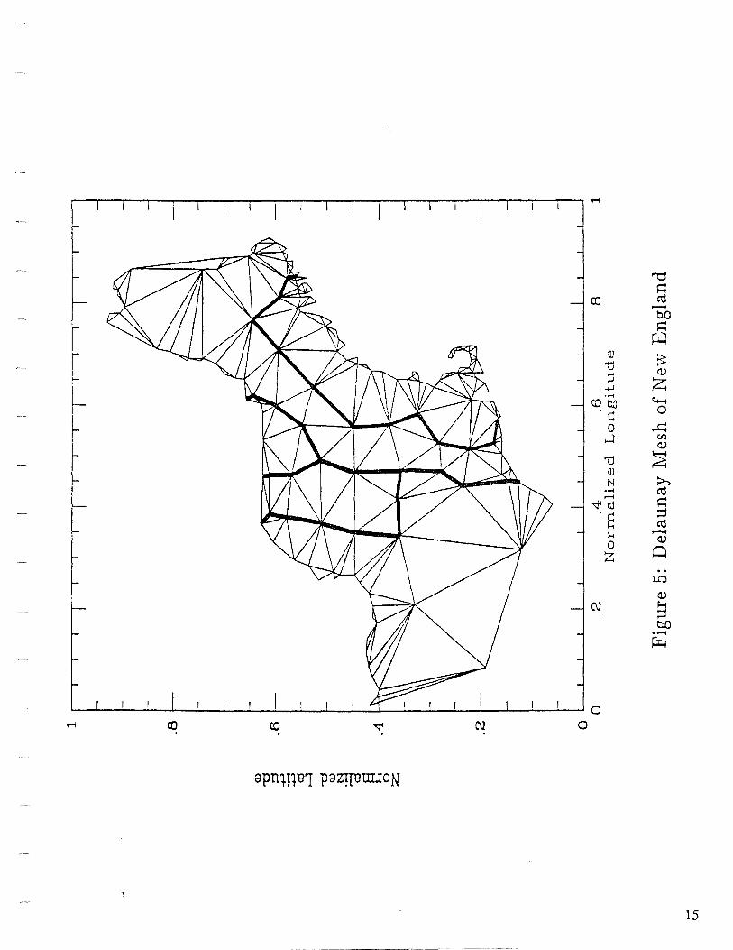
'"'O ~
co ro ,...... OD ~ ~
:v ~ 'ti
:J C,)
..;..) z ...... c.-co t:.ll ·c 0
0 ~ ....J Cl)
C,)
'D Q)
~ N ~ ..... ro ........
~ -.;j4 ro ·s ::::1 ro
s... ,...... 0
C,)
z ~ .. l.Q
C,)
C\l ~ OD ·-~
.___.__...~---------~------~...._.....___.~....__....~~-'---"~_.._~~"------'0
co co 0 .
15
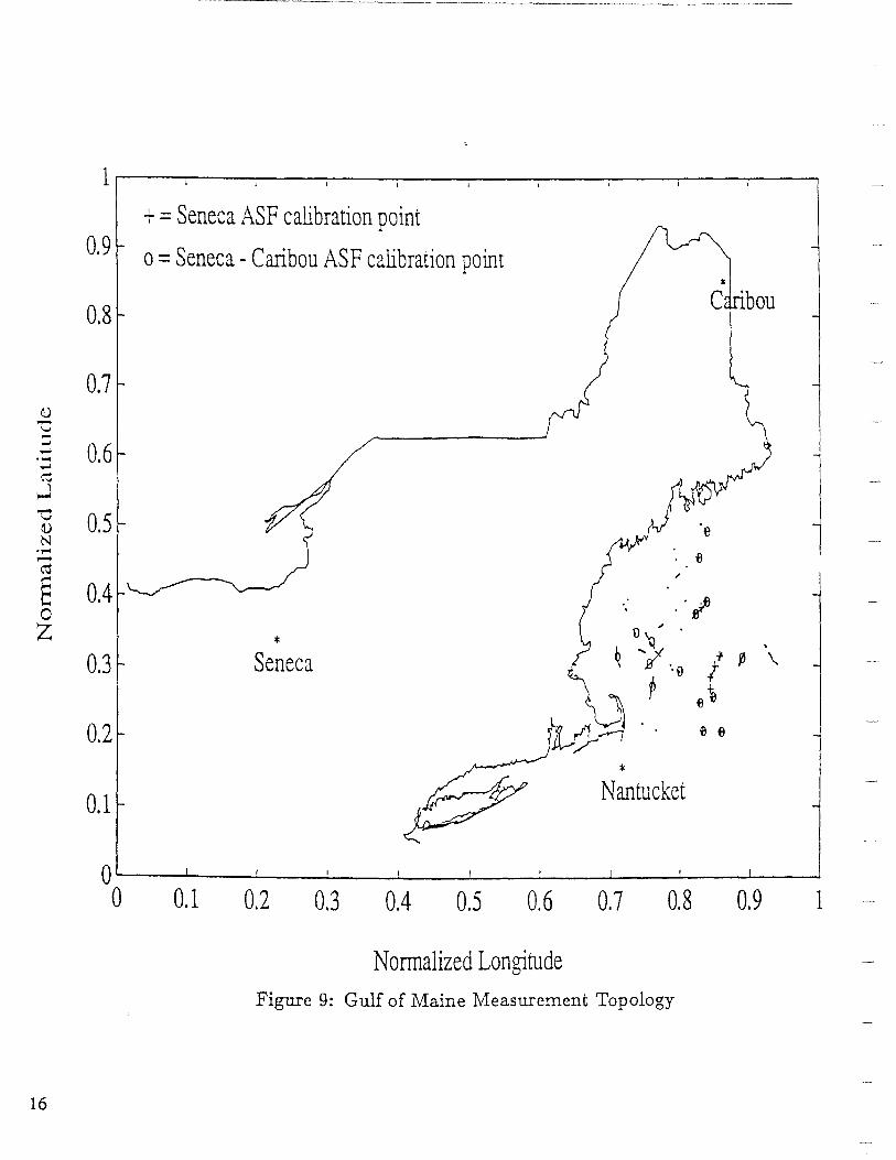
+ = Seneca ASF calibration point 0.9 o =Seneca -Caribou ASF calibration point
* 0.8
C 'bou
0.7 1) -'-' -_.
0.6 ..... ·-;..I ~
~ 'O 0.5 1) . e N ..... e ,..... ~ ,, § 0.4 .·~ 0 z 0 ,. .
* ~ 0.3 Seneca ~ 'JI ··o /., ~ \
p e 1e
0.2 e e
* 0.1 Nantucket
0'--~...._~_.i_~~L.-~...l.-~-L~~'--~....l-~---J.-~--J~---1
0 0.1 0.2 0.3 0.4 0.5 0.6 0.7 0.8 0.9 1
Normalized Longitude Figure 9: Gulf of Maine Measurement Topology
16

,_. -...J
0.40 0.50
<l) 0.40 ~ '"d
\
0.50
\\ \ I \ \ ;:)
~'2,.1 +> •1'""1
+> cd t ) I I~ I C"J
~ l I
] 0.30 E I r J; f 0; I
I
~
cd
s f 11( ( ( j f I
H 0 -z 0.20
C\] ....,
0.60 () .70 0.00
c.n
) ) ) /n11 \ I I
) I 6"4311 I I "3.1
I i /// / / )
I I[)
C'?
I 11 ~VI) /if~~~~
") C'? )'° er)~~ _J \ :J.:::'. __,, ~~ ' ----- 3.1
C'?
"""
0.90 0.50
H 0.40
~ 0.30
~~ 0.20
Q .1 O I !CT I d I I I I I I I I I I I I I I I I I h,,I I I I J----.1 I I I I I I I I I Cl I I I I I I I I I I I I I 0 .10
0.40 0.50 0.60 0.70 0.80 0.90
Normalized Long·i Lt1de Figure 11: Experiment 2, C<dibration 4: Resultant ASF Contour Chart (ASF in microseconds), Detailed Coastline, ·Master-Nantucket Signal

,_. 00 0.40
0.50 0.50 0.60 0.80 0.90
~-o---r iJ I I :r""'\llL3:\ II\ ,l J A 77T""'I: II J I I l 1 I\ 11 I "" I 11 I 0 . 5 0
Q) 0 .4 0 !:'.'.:/ / 111 l~o \ \ \ I ·•• --:-1 . I I ! I IH:\"- \ - (I~~ I "II \Jr-... -l 0.4 0 - . '"d ;:j
+J . ,..... +J
cU ~
'"d o.~o L I 11 I I \ ) '::":. < \ \ \ k "'- )lifc!J,J) • J ( I f\J I I I -. I \ ~ 0.30 Q)
N •...-4 ~
cU
8 ~ 0
z 0.20 ~/ l~l \ F I ~ { I. ~ ) l ff/flt )J'fl\\\\ll~rf'l!_;>,I~ ~·-?\~~ "-... '-----"' -<.q "---" ~ -l 0.20
,....
0
0 .10 11 1 r 1111 1 1 1 1 1 k' 1 1 r !1lLl 1 I' 1 r 11 1 111111 'I '; 1 1 \ 1 I I I I I I I I I I I I I I Q. 1 Q
0.40 0.50 0.60 0.70 0.80 0.90
Normalized Lo11gilude Figure 12: Experiment 3: Resultant ASF Contour Chart (ASF in microseconds), Detailed Coastline,
1vfaster-Caribou Signal

conductivity guess( es), f:l.NED, conductivity result, evaluation set error, calibration set error, mU/meter JLSec mU/meter meters meters . RMS
. RMS maxnnum maXJmum
0.5* 0.0 - 327.1* 97.3* 146.3* 98.1 *
2.828* 0.0 - 633.9* 381.4* 426.3* 380.9* 1.414 -
0.707 -1.414 -2.828 1.350* - 229.2* 57.6 - -
1.414 1.260* - 256.2 51.1 * - -''
0.707 1.195* - 275.7 54.7 68.8* 39.4 1.414 1.265* - 254.7 51.1 89.8 33.1 *
4.000, 2.828 1.265 2.507* 254.9 47.6 42.3 24.1 *
2.000 1.414 4.500 1.000 0. 707 1.264 2.000 1.414 1.112
Table 5: Experiment 2: Detailed Coastline, Master-Nantucket Signal
........
'°

20
GPS-AIDED LORAN-C CALIBRATION: STATIC CASE
• Canadian West Coast Chain (5990) • Pemberton A!ea: height variations - 2000 m • DGPS Static Survey of 11 Points (2DRMS < 1 m) • 24 hour Loran-C Observations at each Station • Loran - GPS: -46 m < ~N < 412 m; -812 m < ~E < 302 m
12300 5100
I I Lorari-C Accuracy at Remote Stations
I I I I Scale ~~-""!"'!'!!!!!!!!!!!!!!!!!!---"!!!!!!!!!!!!!!!!!!!!!! I I o 6 12 18 24 30
Bralorne
-'----~- _I kilometres
Paved Road --- Gravel Road
DN = 412m DE=45m
Tisdall
I DN = 6m I DE= -816m
lg~:~m I Birkenhead Lake
DN =273m DE= -188m
D'Arcy
DN = 177m DE= -90m
DN=-34m DE=-147m
5000
Lachapelle et al. (1991) Analysis of Accuracy and Reliability of Loran-Cat Pemberton, Transportation Develo ment Centre, Trans ort Canada TP 10837E.
Lachapelle & Townsend/En Route Coverage Validation and Calibration of Loran-C with GPS ION GPS 90

LORCAL2 -_SYSTEM
• LoRan cALibration System of The University of CALgary
• Vehicle Mounted Components
• Ashtech LD-XII GPS Receiver • Megapulse Accufix 520 Loran-C Receiver • LocUS Pathfinder Loran-C Receiver • Additional Interface for 3rd Loran-C Unit (Optional) • Toshiba T31 OOSX DC Data Logger • Antenna and Equipment Racks • Total Weight: < 100 lbs
• Monitor Unit Components
• Ashtech LD-XII GPS Receiver • Additional Interface for Loran-C Unit (DLC Testing/Optional) • Toshiba T5200 AC Data Logger (&Processing)
• Performance
• DGPS Accuracy < 5 m • GPS/Loran-C Data Rate < 0.2 Hz (T = 5 s) • Normal Cruising Speeds
©Lachapelle & Townsend/En Route Coverage Validation and Calibration of Loran-C with GPS IONGPS 90 21

Analysis of Accuracy and Reliability of Loran-C at Pemberton TDC(fP10837E
IEN=JROU1rJE JLOJRAN=C WJI1LH DCGP§
CALJIJRJRA 1fKON ( li/2)
• Use of LORCAL2 • 30-km profile between Pemberton Airport and Hollandia • Northing: both directions are in close agreement • Relative changes > 500 m over distances of a few km
500
400
300
~ 200
100 (/) (1) ,_
0 -(1)
~ -100
-200
-300
-400
-500 0 4 8 12 16 20 24 28
Distance (km)
Northing: Direction East to West (Hollandia/Airport)
500 -----------------.---
400
300
200
100
-100
-200
-300
-400
-500 ---...----...--..----..---.-__,..___,..__,...___,..__,.._
0 4 8 12 16 20 24 28 32
Distance (km)
Northin : Direction West to East (Hollandia/A' ort) 22 G. Lachapelle et al. (1991) Surveying Engineering/University of Calgary

Analysis of Accuracy and Reliability of Loran-C at Pemberton TDCfTPl 0837E
JEN =ROUI'JE lLOJP(AN =CC Wlil'H DGJP§
CCA1LliI83JP(A TliON (2/2)
• Use of LORCAL2 • 30-km profile between Pemberton Airport and Hollandia • Easting • Relative changes> 300 mover distances of a few km
500 -.-------------------.
400
300
200
-100
·200
-300
-400
-500 ~--...--,...---.,..---..-.----.---.--.----.--.---.---.--~.......-i 0 4 8 12 16 20 24 28 32
Distance (km)
Easting: Direction East to West (Hollandia/ Airport)
500
400
300
200
en 100 Q) ._
0 -Q)
ii ~ -100
-200 ~\ -300
-400
-500 0 4 8 12 16 20 24 28 32
Distance (km)
G. Lachapelle et al. (1991) Surveying Engineering/University of Calgary 23

Analysis of Accuracy and Reliability of Loran-C at Pemberton TDC{I'Pl0837E
JEJFJFIEC1r AC1rTIVTI1rTIIES
OJF ON
GIEOMAGNJETTIC 1L0It{AN=C STIGNAILS
• Geomagnetic activity: measure of the dynamics or rate of change in the Earth's magnetic field
• High level of geomagnetic activity can affect RF propagation and the operation of electrical and electronic equipment
• Level of geomagnetic activity is correlated to solar activity, quantified by the sunspot number (Kunches & Hirman, 1990):
2
17~ 19
a.. Cl> .c E 21 ::::s 18 z c -0
9 y c. c t/) c: 20 L ::::s 17 en 11 E
"C 10 Cl> 8 .c: 15 - 7 0 12 0 13 E 16 en 14
5
2
o~:::_ __ _J 0 6 12 18 24 30 36 42 48 54 60
Months After Minimum (Sept. 86)
Amplitudes of Current (No. 22) and Previous Solar Cycles
• In most cases, the effect on equipment is negligible • Lower height of D-layer may cause skywave interference • Loran-C observations in S rin 89: near solar maximum
24 G. Lachapelle et al. (1991) Surveying Engineering/University of Calgary

Analysis of Accuracy and Reliability of Loran-C at Pemberton TDC!I'Pl 0837E
AURORAL AND §U~=AURORAL GIEOMAGNIE1LKC AC1LliVli1LliIE§
• Average auroral zone & Geomagnetic observatory network
0 500 1000
Kilometres • Magnetic Observatory
• Auroral & Subauroral Geomagnetic Activity - May 89/Feb 90 • 1 nanoTelsa: 1 Newton per Ampere-metre • Auroral - active if> 161 nT; sub-auroral - active if> 41 nT
600
·· - -----··-.Auroral-··--
Subauroral Ot=:~~:..:.=~,,.=.::::!,:!~=:::;:::::::::..::::~.....:.;::.::::.::::...:;:.:"':::::~~
0 303 Days Since May l, 1989
G. Lachapelle et al. (1991) Surveying Engineering/University of Calgary 25

Analysis of Accuracy and Reliability of Loran-C at Pemberton
GIEOMAGNIE1LJIC AC1LJIVJI1LJIJE§ VJER§U§ LORAN-C §NR
TDCrrP10837E
• Cross-correlations between levels of geomagnetic activity and SNR values. No positive or negative signal, implying that no significant level of correlation
900
x -100 .._ ________________ _
0 303 Time Lag (days)
Cross correlation between auroral geomagnetic activity and SNR at Pemberton from the Master and Secondary Transmitters
300
-100 ...__ _____________ ____.
0 303 Time Lag (days)
Cross correlation between subauroral geomagnetic activity and SNR at Pemberton from the Master and Second Transmitters
26 G. Lachapelle et al. (1991) Surveying Engineering/University of Calgary
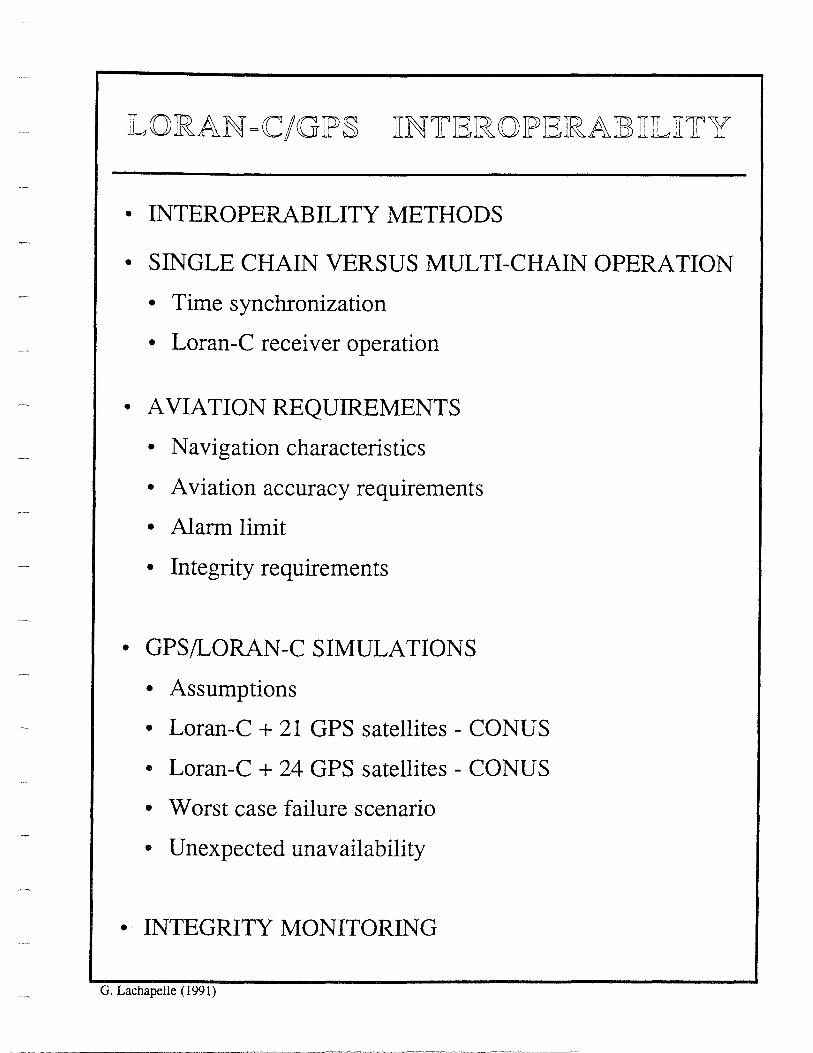
LO IRAN =CC/GJP§ ITN1LIEIROJPIEJRAIB3li1Lli1LY
• INTEROPERABILITY METHODS
• SINGLE CHAIN VERSUS MULTI-CHAIN OPERATION
• Time synchronization
• Loran-C receiver operation
• AVIATION REQUIREMENTS
• Navigation characteristics
• Aviation accuracy requirements
• Alarm limit
• Integrity requirements
• GPS/LORAN-C SIMULATIONS
• Assumptions
• Loran-C + 21 GPS satellites - CONUS
• Loran-C + 24 GPS satellites - CONUS
• Worst case failure scenario
• Unexpected unavailability
• · INTEGRITY MONITORING
G. Lachapelle ( 1991)

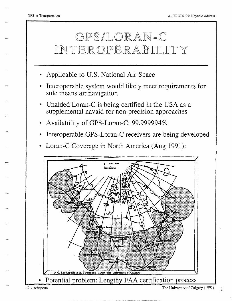
GPS in Transponation ASCE GPS '91: Keynote Address
GJP§/JLOJRAN =C TIN1rJEJR 0 JPJEJRAJB3 TIJLTITY
• Applicable to U.S. National Air Space
• Interoperable system would likely meet requirements for sole means air navigation
• Unaided Loran-C is being certified in the USA as a supplemental navaid for non-precision approaches
• Availability of GPS-Loran-C: 99.999994%
• Interoperable GPS-Loran-C receivers are being developed
• Loran-C Coverage in North America (Aug 1991):
• Potential G. Lachapelle
0 400 800 11110liiWei '
FAA certification rocess The University of Calgary (1991) 1

GJP§/]LOJRAN =<C 1IN1LIER 0IPIERAJE1I1L1I1f Y MIE 1f ~J 0 D §
(1) Loran-C as the GPS Integrity Channel CGIC)
• Positions using unaided GPS • Loran-C used to communicate health information
(2) 2-D position comparison
• GPS and Loran-C receivers operate independently • Positions are compared on a frequent basis • Alarm to pilot sounds if 8<t> and 8A. exceed preset threshold
(3) GPS & Loran-C pseudoranges
• Hydrid receiver to combine pseudoranges • Loran-C and GPS transmitters time offsets must be known • Loran-C pseudoranges can be calibrated in real-time or using a
predetermined database
( 4) GPS pseudorangees & Loran-C Time Differences
• Low level hydrid system is sufficient
(5) Loran-C direct ranging using GPS time transfer
• Use of GPS to synchronize Loran-C receiver • Loran-C transmitters and GPS satellites time offsets must be
known
Ref: K. L. Van Dyke (1990)The Status and Future of GPS/loran-C Interoperability. Proceedings of 19th Annual Technical S m osium. WGA, . 123-130
2 © G. Lachapelle, The University of Calgary (1991)

USING GPS TO SYNCHRONIZE LORAN CHAINS
• Loran transmitter are grouped in chains.
• Each chain has a unique group repetition interval (GRI).
• Transmitters in different chains are not synchronized.
• Consequently, receiver can only compute TDs between signals with the same GRI.
• Dual rate receivers exist.
•These compute use 2 stations in one chain and 2 stations in another chain.
• Today, receivers require pairs.
3

4
--
Single vs. Multi-C-hain Operation
• Single Rate: The Receiver Can Only Use Stations from a Single Group Repetition Interval, GRI (Most Current Receivers).
• Two Pair Fixing: The Receiver Can Use 2 Stations in One GRI and the 2 Other Stations in Another GRI.
Note: This is Useful Because Almost All Stations are Dual-Rated.
• Chain Independent: The Receiver Can Use Any 3 or More Stations Regardless of which GRI They Are in.
• Possible Since Master Stations are Synchronized to within 100 ns. Must Analytically Correct for Seasonal Deviations if High Accuracy is Required.
• Most Effective for Straightforward Combination with GPS Signals.

'-. / ' / "'-<lo / -.....:: o,.,, -- _... -........;.; .........._ - - ----
.\ \ \ \ I I I I I J
I I
I /
MP1199-A-11
Figure 1
Loran-C Accuracy (Assuming TD Measurement Standard Dev=- 100 nsec) for:
2 station chains (-thin line) 2 pair fixing (- thick line) 1 pair/ 1 station fixing (----- dotted line)
5

0\
Digital Loran-C Receiver Blocl{ Diagra111
I I I I
\[7 I I
Time . Data Reference ....
Port I I I I I I I I I I , 11r I I I I I I
. ~
Notch AJD - - Keyboard Coupler L . Amplifier L Processor ... Filters - - Converter
I Display I I J -
I I -- I I I I I
il ' I I I I I I . I
I Antenna Analog Digital Signal Processing 1 Control/Display
I
•Automatic Gain Control: provides a constant signal level to AID converter to maximize Quantization Accuracy
•Processor averages "all" Loran-C pulses

Loran-C Receiver Operation
• • • • • •
Initialization Acquisition of Pulse Groups Identify 6th zero crossings Track Selected Stations Apply Propagation Corrections Coordinate Conversion
Loran-C Accuracies (Overall System)
• Predictable • Repeatable • Relative
Receiver Error
460 m (95%) (SNR 1:3) 18-90 m 5-90m
• RMS Tracking Noise Typically 10 m (5 seconds averaging; SNR 1:3) Small Portion of Overall Error Budget
• All-Digital Receivers Could Increase Coverage and Decrease RMS Tracking Noise by Using all Available Loran-C Information. Predictable Loran-C ·Accuracy Would not Be Improved.
7

8
GPS in Transportation ASCE GPS '91: Keynote Address
NA VTIGA 1fTION CJHIARAC1fIERTI§ TJIC§
• fredictable or Absolute Accuracy: Accuracy with respect to a reference coordinate system.
• Repeatable Accuracy: Accuracy with which one can return to a position determined previously with the same system
• Relative Accuracy: Accuracy of position w.r.t. that of another position; or accuracy of position w.r.t. position in recent past.
• Reliability: Probability of performing a specified function without failure under given conditions for a specific time period
• Inte2rity: Ability to provide timely warnings when the system should not be used
• Availability: % of time a system is available
• Coyera2e: Area in which a specified accuracy can be obtained
• . Update Rate: Frequency with which positions are provided or required
G. Lachapelle The University of Calgary (1991)

Aviation Accuracy Requirements
Current System (1).
(1) Accuracy Requirements Future System
Phases of Flight AC90-45A Accuracy Requirements
95% conf. for cross track and along track 2 drms
Enroute Domestic 1.5 nmi 1000 m
Terminal 1.1 nmi 500 m
Non-Precision Approach 0.3 nmi 100 m
( 1) System Accuracy Requirements Do Not Include Flight Technical Error (F"l'E). (FfE manual: enroute + 2 nmi; terminal + 1 nmi; approach + 0.5 nmi)
9

-------- ------ ----
Non-Precision Approach Example
POSITIONING INTEGRITY
Probability Alarm Probability
Accuracy of of Limit
Exceeding Exceeding
100 0.05 555 (3.6) 1 o-8
meters global avg. meters per hour
10

~t\. VIATION USE REQUIRES INTEGRITY:
• System Warns Users When System Suffers Fault
• Warning Occurs Before User Error Exceeds '~Protection Limit"
• Probability of False Alarm is Small
• Probability of Undetected Fault is Small
• Supplemental Nav: Faults Must Be Detected
• Sole Means Nav: Faults Must Be Detected and Isolated
• Two Approaches
INTEGRITY CHANNEL
• Loran is Sole Means For Approach to Airports With Signal Monitors
• GPS Could Be Sole Means Using a GIC
• Inmarsat Geostationary Overlay
11

,..._. N
GPS Integrity Requirements
RTCA Sgecial Committee 159
I Performance Item I Phase of Flight Maximum Time to MinimupJ
Alarm Limit Allowable Alarm Detection Alarm Rate Probability
En Route 2.0 nmi 0.002/Hr 30 seconds 0.999
Terminal 1.0 nmi 0.002/Hr 10 seconds 0.999
RNA V Approach 0.3 nmi 0.002/Hr 10 seconds 0.999
Table 1. Tentative GPS Integrity Perf onnance Requirements16

OVERVIEW oF aPS/LoRAN coMPliTER SIMuLATloN
INITIALIZATION
FOR EACH LOCATION
FOR EACH TIME
• CALCULATE GPS VISIBILITY
• CALCULATE LORAN SNRs
• CALCULATE HDOPs FOR ALL SUB-SETS OF USABLE SIGNALS (ELEVATION> 7.5°; SNR > -lOdB)
• WRITE COVERAGE DATA TO FILE
FOR ALL COMBINATIONS OF UP TO 6 SIMULTANEOUS FAILURES
• DETERMINE BEST VALUE OF HDOP FOR WORST CASE FAILURE
·-
• IFBESTHDOP > 10; WRITE OUTAGE DATA TO FILE
END FAILURE LOOP
END TIME LOOP
END LOCATION LOOP
02X. 027 /002. £27
13

14
Computer Simulation Assumptions
GPS • Elevation Angle > 7 .5° • 21 or 24 Satellites • Satellite Mean Time to Failure:
MTTF = 7.5 Years • Satellite Mean Time to Repair:
MTTR == 1 or 2 Months
Loran-C • Loran-C Pseudoranging • Signal-to-Noise Ratio> -10 dB (1:3) • Receiver Bandwidth= 20 kHz • Atmospheric Noise Level Exceeded 2%
of the Time • Mid-Continent Transmitters Operational • Transmitter MTTF = 1500 Hours • Transmitter MTTR = 35 Minutes
Time Increment 6-10 Minutes
Horizontal Dilution of Precision < 10 (if applicable)
Model Generates Conservative Results

GPS/Loran-C Coverage of CONUS
w J.1J"N a
~
so'N
LtJ J.IJ• N 0
~
Loran-C + 21 GPS Satellites
AREAS WITH 8 OR MORE SIGNALS WORST CASE
LONGITUDE
AREAS WITH 10 OR MORE SIGNALS DAILY AVERAGE
LONGJTlJOE
15

16
····-·····-··········-----------
GPS/Loran-C Coverage of CONUS
so• N
Loran-C + 24 GPS Satellites
AREAS WITII 9 OR MORE SIGNALS WORST CASE
zo' N _,___._....___.---.....-....; .......... ........,_.._..........._.....___,_....._..__.__._....__._--"'!'"-__. us• w 10s• w as• w
w .c.o' N 0
~
LONGITUDE
AREAS WITH 11 OR MORE SIGNALS DAILY AVERAGE
LONGITUDE
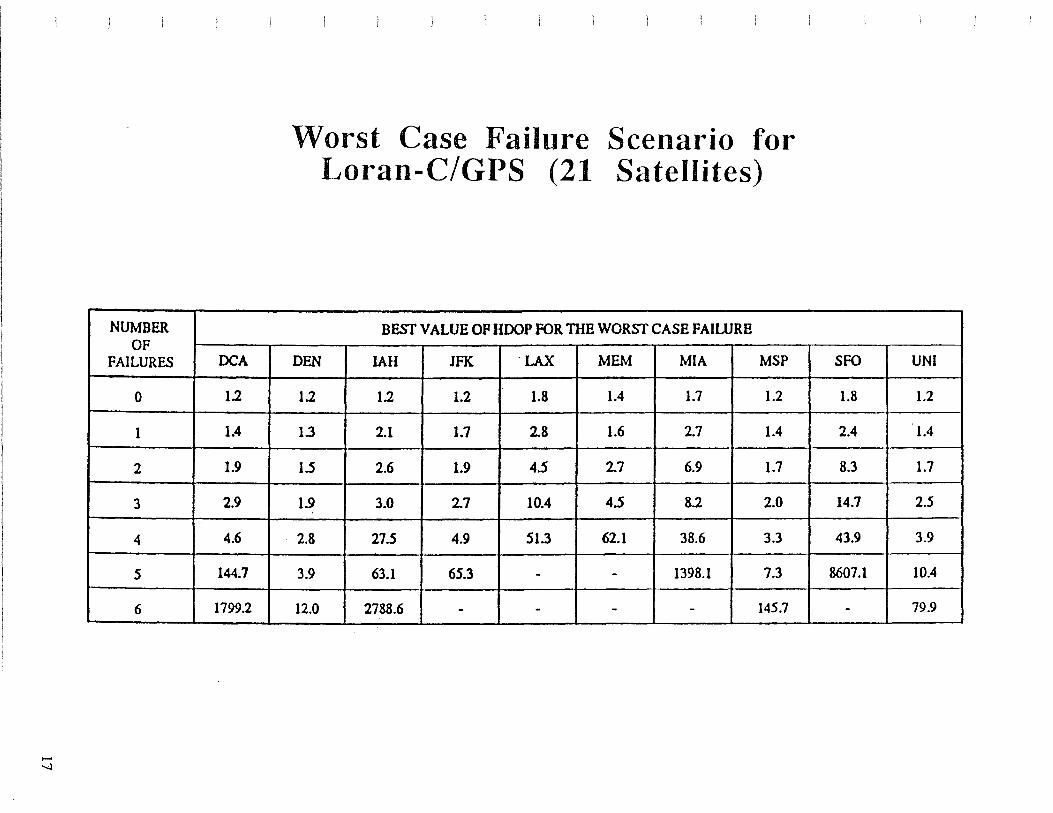
NUMBER OF
FAILURES OCA
0 1.2
1 1.4
2 1.9
3 2.9
4 4.6
5 144.7
6 1799.2
........ -.-.)
Worst Case Failure Scenario for Loran-C/GPS (21 Satellites)
BESf VALUE OF HOOP FOR TIIB WORSf CASE FAIWRE
DEN IAH JFK ·LAX MEM MIA MSP
1.2 1.2 1.2 1.8 1.4 1.7 1.2
1.3 2.1 1.7 2.8 1.6 2.7 1.4
1.5 2.6 1.9 4.5 2.7 6.9 1.7
1.9 3.0 2.7 10.4 4.5 8.2 2.0
2.8 27.5 4.9 Sl.3 62.1 38.6 3.3
3.9 63.1 65.3 - - 1398.1 7.3
12.0 2788.6 - - - - 145.7
SFO UNI
1.8 1.2
2.4 1.4
8.3 1.7
14.7 2.5
43.9 3.9
8607.1 10.4
- 79.9

18
Markov Model for the Determination of GPS/Loran-C Availability

GPS/Loran-C State Probabilities
STATE PROBABn.rrt' APTER 2 YRS. PROBABn.rrt' AFTER 2 YRS. OPS LORAN OPSMTTR• I MON'llf GPS MTTR • 2 MON'llf PAD.lJRES FAn.l.J'R.ES
0.79 0.62 0 0
2 0.11 0.29 0
3 0.007 0.005 0
4 0.02 0.0.SS 2 0
$ 0.002 0.003
6 0.00003 0.00003 0 2
7 0.001 0.009 3 0
' 0.0002 0.0006 2
9 0.000007 0.00001 2
10 O.OOOOOOOI OJXfX:lm7 0 3
11 0.00007 0.0009 4 0
12 0.00001 O.OOOCI 3
13 0.0000CX)I O.oooo02 2 2
14 0.00000002 o.ooocmn 3
u 0 ocaxxxxJ02 0 <XX1XfX'/.XJ9 0 4
16 0.000003 0.00006 $ 0
17 0.0000006 o.oooooa 4
u O.OOOXXXlS 0.000003 3 2
19 o.ocoooooaz O.rxmxt1J7 2 3
20 o.ocaxiooooocs O.OOOOOOX07 4
21 o.ooooooocxm O.OOCXX>X006 0 $
22 0.00000003 O.OOOOOCI 6 0
23 0.00000002 0.0000006 $
24 0.000000003 o.oooooooc 4 2
2$ 0.ocaxxxxJOl o.ooooooooz 3 3
26 0.00000000003 o.ooooooxos 2 4
'27 o.ooooooocoo.z o.oooooxoo.s $
2& o.ooooocxxxm o.ooocm:oos 0 6
29 o.ooooooocoo.z O.oocxroxXlS 2:7
19

20 02X . 027 /004. !:27
AVAILABILITY PROCESSING
GPS/LORAN
SIMULATION
OUTAGE RECORDS
MERGE
AYAILABILITY
GPS/LORAN
MARKOV MODEL
STATE
PROBABILITIES
p (OUTAGEi) = p STATE X p COMBINATION1X p TIME
AVAILABILITY= 1 - L p (OUTAGEi) all pouibJc
outages

GPS/Loran-C (21
Expected Unavailability GPS Satellites)
EXPECTED UNA V AlLABIUTY PER YEAR
LOCATION 21 GPS SA TEWTES 21 GPS SA TElllTES All LORAN STATIONS LORAN MASTER STATIONS
DCA < 1 second 8 mi.nu~
DEN < 1 second 12 minutes
IAH < 1 second Shoun
JFK < 1 second Sminu~
LAX 1 second 39 hours
MEM 1 second 3boun
MIA 35 seconds 22boW1
MSP < 1 second < 1 second
SFO 69 seconds 59boun
UNI < 1 second 10 minutes
AVERAGE 11 seconds 13 hours
21

22
GPS Integrity Monitoring
• Space/Control Segment. Not Sufficient: Some Satellite Malfunctions May Take up to One Hour to Detect.
Loran-C
• Real Time Monitor Network • By 1992: Aviation Blink (Repetitive on/off
Pattern of First Two Pulses of Secondary Transmitter Initiated within 10 Seconds of Out-of-Tolerance Condition).
=>Will Allow for Non-Precision Approaches • Wrong Cycle Acquisition Is still an Issue
(Mostly for low SNR).
Receiver Autonomous Integrity Monitoring
• Provides both OPS and Loran-C Integrity. Cost: Reduced Availability.
Example of Worst Case Location
SCENARIO I UNAVAILABILITY OP I UNAV All.ABILITY OP I rosmON'FIXING INTEGRITY
GPSPRIMARY 11 sec/year 1.4 hrs/year MTIR - 2 MONTHS
GPSPRIMARY 2scc/year 15 min/year MTfR - 1 MONTH
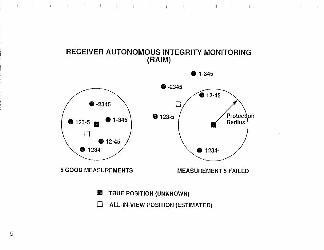
N tu
RECEIVER AUTONOMOUS INTEGRITY MONITORING (RAIM)
·-2345
• 123-5 • • 1-345
D • 12-45
5 GOOD MEASUREMENTS
• 1-345
·-2345
• 123-5
MEASUREMENT 5 FAILED
• TRUE POSITION (UNKNOWN)
0 ALL-IN-VIEW POSITION (ESTIMATED)

24
RECEIVER AUTONOMOUS INTEGRITY l\/IONITORING
• No External Health Monitors
• Many Techniques
• Maximum Separation Algorithm (G.Bro-vvn and P.McBurney, 1988)
• K Pseudoranges
- Compute K Subfixes With K - 1 Pseudoranges
- If Maximum Separation Exceeds Threshold, Then Declare Fault
• RAIM Demands Excellent Signal Geometry
• FD: All K Subsets With K - 1 Pseudoranges Must Have Small HDOP
• FI: All K (K - 1)/2 Subsets With K - 2 Pseudoranges Must Have Small HDOP

N Lil
POSITION ESTIMATOR .. (LIL)
[)Q[)
/ /
/ /
"
/ /
/ /
/ /
/
__________ ,...... -----
----------------------- ..
Figure 1: A GPS/Loran Hybrid Which Combines GPS Pseudoranges With Loran Pseudoranges

N
°'
[)Q{] _____ _.,.
--------------------....._....._ _____ _
POSITION I ESTIMATOR (LJU GPS
I l COMPARATOR I
POSITION I ESTIMATOR (LJU LORAN
1
........ _ ...... _ ...... __ ...
Figure 2: A CPS/Loran Hybrid Which Compares Independent Latitude and Longitude Estimates
FAULT DETECTION

GPS/Loran-C Measurement Geometry
-+ Si position vector satellite i -+ u user position vector -+ ei line-of-sight vector for satellite i
~
L'· I
~
position vector LORAN-C transmitter corrected for earth curvature
Li position vector LORAN-C transmitter
U user position vector
~ e i line--of-sight vector for transmitter i
27

28
GPS/Loran-C Receiver Architectures
\ [7
OPS RF
a.OCK . RBCEIYa
lPROCJWOR a.ocx
J
RNAV
USJ!lt INTHRPACE
SEPARATED
\ [7
l..OllAN..C JU'
• RECEIVD.
PROCESSOR
. JtHAV
• ~
tmDl IHTEJlFACE
OPS LORAN..C RF RF
RNAV
USER INTERFACE
HYBRIDIZED

-
GPS/Loran-C Navigation Solution
• Combine Pseudoranges
• Use Any Combination of 4 Measurements from 4 Sources. Issue: Clock Offset between GPS and Loran-C time= 345 ns (95%), mostly Caused by Selective Availability.
• Use an Additional Measurement Source to solve for the Clock Offset between GPS and Loran-C.
• Combine GPS Pseudoranges with Loran-C Time Differences:
4 GPS Pseudoranges + 0 Loran-C TDs
3 GPS Pseudoranges + 1 Loran-C TD (2 Stations)
2 GPS Pseudoranges + 2 Loran-C TDs (3 Stations)
29

30
Hybrid GPS/Loran-C Navigation Solution 2-D Pseudorange and Time Difference
STATION 1 (X ,Y)
1 1
Pseudorange:
USER (X,Y)
STATION2 (X ,Y )
2 2
Time Difference: TD 12
= R2 + b - R
1
B =User Clock Offset (in meters)

Linearization of Measurement Eqn.
A A ax x-x. Y-Y.
dpi = l l 1 t:.Y
A A
Rt Rt t:.B
A A A A ax x-x. x-x. Y-Y. Y-Y.
t:.TD .. = 1 l 1 l 0 t:.Y -lj " A A " R. R. R. Ri t:.B 1 l J
General Equation: t:.Y = Ht:.B.
• Pseudoranges: Can Use Single Loran-C Transmitters, Need Propagation Corrections in Different Format for Fewer Propagation Paths. Solve for Offset with Respect to Loran-C Time.
• Pseudoranges +Time Differences: ·Must Use Loran-C Transmitter Pairs; Can Use "Standard" TD Propagation Corrections.
NOTE: if Using Loran-C Pseudoranges, One Must Correct for Receiver Hardware Delays (Can be Time-Varying 50-500 ns).
31

32
Prototype Hybrid GPS/Loran Receiver
\V PRE-AMPLIFIER
GPS RECEIVER
4-CHANNEL
·Ir
\V PRE-AMPLIFIER
LORAN-C TIME-OF·ARRIV AL
RECEIVER 8-CHANNEL
DATA STORAGE ~ 11ICRO-C01\.1PUTER
OPERATOR INTERFACE
CDI

Keyboard Input
Waypoints Simulated Step and Ramp Failures Enroute/ Approach Modes
(+ 5 nmi I+ 1.25 nmi CDI Scaling)
Received Data
GPS Data (Once per Second) Pseudoranges, Time, Satellite ID, Ephemerides, Receiver Health.
Loran-C Data (Once per Second) Pseudoranges, Time, Station ID, Receiver Health, SNR.
Flight Test Emphasis
Operational Verification of GPS/Loran-C Preliminary Assessment of Impact of Failure Modes
33
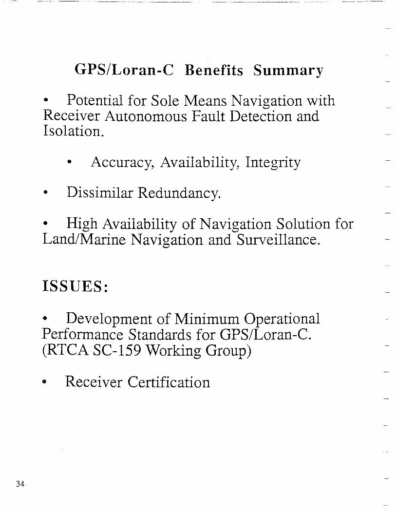
34
GPS/Loran-C Benefits Summary
• Potential for Sole Means Navigation with Receiver Autonomous Fault Detection and Isolation.
• Accuracy, Availability, Integrity
• Dissimilar Redundancy.
• High Availability of Navigation Solution for Land/Marine Navigation and Surveillance.
ISSUES:
• Development of Minimum Operational Performance Standards for GPS/Loran-C. (RTCA SC-159 Working Group)
• Receiver Certification