Look Way Up GM V6-engine plant - gorbel.com · Cadillac CTS. GM responded to the materi-als...
2
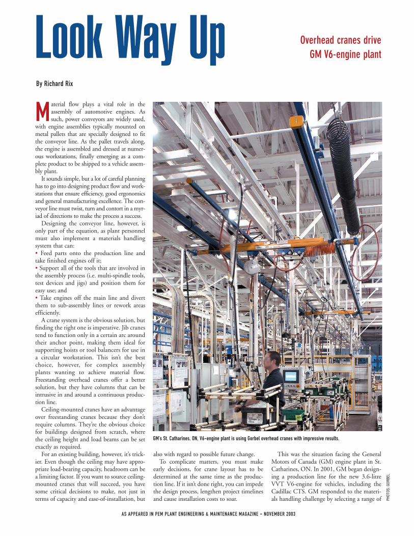
M aterial flow plays a vital role in the assembly of automotive engines. As such, power conveyors are widely used, with engine assemblies typically mounted on metal pallets that are specially designed to fit the conveyor line. As the pallet travels along, the engine is assembled and dressed at numer- ous workstations, finally emerging as a com- plete product to be shipped to a vehicle assem- bly plant. It sounds simple, but a lot of careful planning has to go into designing product flow and work- stations that ensure efficiency, good ergonomics and general manufacturing excellence. The con- veyor line must twist, turn and contort in a myr- iad of directions to make the process a success. Designing the conveyor line, however, is only part of the equation, as plant personnel must also implement a materials handling system that can: • Feed parts onto the production line and take finished engines off it; • Support all of the tools that are involved in the assembly process (i.e. multi-spindle tools, test devices and jigs) and position them for easy use; and • Take engines off the main line and divert them to sub-assembly lines or rework areas efficiently. A crane system is the obvious solution, but finding the right one is imperative. Jib cranes tend to function only in a certain arc around their anchor point, making them ideal for supporting hoists or tool balancers for use in a circular workstation. This isn’t the best choice, however, for complex assembly plants wanting to achieve material flow. Freestanding overhead cranes offer a better solution, but they have columns that can be intrusive in and around a continuous produc- tion line. Ceiling-mounted cranes have an advantage over freestanding cranes because they don’t require columns. They’re the obvious choice for buildings designed from scratch, where the ceiling height and load beams can be set exactly as required. For an existing building, however, it’s trick- ier. Even though the ceiling may have appro- priate load-bearing capacity, headroom can be a limiting factor. If you want to source ceiling- mounted cranes that will succeed, you have some critical decisions to make, not just in terms of capacity and ease-of-installation, but also with regard to possible future change. To complicate matters, you must make early decisions, for crane layout has to be determined at the same time as the produc- tion line. If it isn’t done right, you can impede the design process, lengthen project timelines and cause installation costs to soar. This was the situation facing the General Motors of Canada (GM) engine plant in St. Catharines, ON. In 2001, GM began design- ing a production line for the new 3.6-litre VVT V6-engine for vehicles, including the Cadillac CTS. GM responded to the materi- als handling challenge by selecting a range of Overhead cranes drive GM V6-engine plant Look Way Up By Richard Rix GM’s St. Catharines, ON, V6-engine plant is using Gorbel overhead cranes with impressive results. PHOTOS: GORBEL AS APPEARED IN PEM PLANT ENGINEERING & MAINTENANCE MAGAZINE - NOVEMBER 2003
Transcript of Look Way Up GM V6-engine plant - gorbel.com · Cadillac CTS. GM responded to the materi-als...
M aterial flow plays a vital role in theassembly of automotive engines. Assuch, power conveyors are widely used,
with engine assemblies typically mounted onmetal pallets that are specially designed to fitthe conveyor line. As the pallet travels along,the engine is assembled and dressed at numer-ous workstations, finally emerging as a com-plete product to be shipped to a vehicle assem-bly plant.
It sounds simple, but a lot of careful planninghas to go into designing product flow and work-stations that ensure efficiency, good ergonomicsand general manufacturing excellence. The con-veyor line must twist, turn and contort in a myr-iad of directions to make the process a success.
Designing the conveyor line, however, isonly part of the equation, as plant personnelmust also implement a materials handlingsystem that can:• Feed parts onto the production line andtake finished engines off it;• Support all of the tools that are involved inthe assembly process (i.e. multi-spindle tools,test devices and jigs) and position them foreasy use; and• Take engines off the main line and divertthem to sub-assembly lines or rework areasefficiently.
A crane system is the obvious solution, butfinding the right one is imperative. Jib cranestend to function only in a certain arc aroundtheir anchor point, making them ideal forsupporting hoists or tool balancers for use ina circular workstation. This isn’t the bestchoice, however, for complex assemblyplants wanting to achieve material flow.Freestanding overhead cranes offer a bettersolution, but they have columns that can beintrusive in and around a continuous produc-tion line.
Ceiling-mounted cranes have an advantageover freestanding cranes because they don’trequire columns. They’re the obvious choicefor buildings designed from scratch, wherethe ceiling height and load beams can be setexactly as required.
For an existing building, however, it’s trick-ier. Even though the ceiling may have appro-priate load-bearing capacity, headroom can bea limiting factor. If you want to source ceiling-mounted cranes that will succeed, you havesome critical decisions to make, not just interms of capacity and ease-of-installation, but
also with regard to possible future change.To complicate matters, you must make
early decisions, for crane layout has to bedetermined at the same time as the produc-tion line. If it isn’t done right, you can impedethe design process, lengthen project timelinesand cause installation costs to soar.
This was the situation facing the GeneralMotors of Canada (GM) engine plant in St.Catharines, ON. In 2001, GM began design-ing a production line for the new 3.6-litreVVT V6-engine for vehicles, including theCadillac CTS. GM responded to the materi-als handling challenge by selecting a range of
Overhead cranes drive GM V6-engine plant Look Way Up
By Richard Rix
GM’s St. Catharines, ON, V6-engine plant is using Gorbel overhead cranes with impressive results.
PHOT
OS:G
ORBE
L
AS APPEARED IN PEM PLANT ENGINEERING & MAINTENANCE MAGAZINE - NOVEMBER 2003
Gorbe l c e i l ing -mounted c r ane s tha t achieve ease-of-movement and load-handlingstrength, while conforming to existing build-ing parameters.
The “World’s Best Powertrains” are pro-duced at the St. Catharines plant, accordingto signs inside and outside the building. Thenew V6 is the first variation of the global 6-cylinder to go into production and representsa $440-million investment at the plant.Producing 255-hp and 252 lb-ft of torque,the 3.6-litre engine is approximately 16 per-cent more powerful than the old CTS engine.The plant also builds the GEN III V8-enginefor SUVs and the 5.7-litre aluminum blockV8 for the Chevy Corvette.
GM researched many kinds of cranes toservice the new V6 production line beforeselecting the Gorbel range. An importantconsideration was the Gorbel products’ flexi-ble runway construction, whichallows the cranes to be installed ina way that complements the exist-ing building, rather than have tomake major structural changes.
Headroom was another key fac-tor in crane selection. Heightrestrictions to the top of the runwayimposed a challenge, both to thedesign engineering team and instal-lation workers. It was crucial for them to beable to source a suitable product “off-the-shelf,” without having to resort to major mod-ifications.
To reduce costs, the installation also calledfor 20-foot support centres along the lengthof the crane runway. Even with just 1,000-pound lift capacity crane equipment, somesuppliers would’ve faced a problem meetingthis requirement, but Gorbel was able torespond to the challenge and satisfy GM’sneed to lift loads of up to 4,000 pounds.
Among other complicating factors at the
St. Catharines plant was that available clearheight isn’t always consistent. The responsewas to install plain track on one side, whereheadroom is low (mountings every 6 feet)and truss track on the other side, where head-room is less of a problem (20-foot spacedmountings). The capability exists to go to 30-foot spaced mountings in the plant.
One of the factors contributing to thecranes’ operational success is their uniquealuminum design. For easier operator han-dling, Gorbel uses high-strength aluminumalloy that reduces bridge dead weight by upto 40 percent compared to steel. Reducedweight also creates unparalleled flexibility,in terms of combining spans, capacities,load weights and ease-of-movement into asuccessful system.
Aluminum bridges used on steel runwaysprovide a cost-effective solution to most over-
head handling challenges. As well as being easyto install, such systems are relatively simple toexpand and modify in the field. The trackdesign allows the user to create precise trackalignment. Users can often insert new craneson existing runways, as their lifting needsincrease. In fact, the Gorbel equipment createsthe flexibility to install up to four 1,000-poundbridges on the same runway.
The use of aluminum bridges also facili-tates the installation of high-speed precisionhoists under pendant control. That’s becausethere’s less “bounce” in load handling com-
pared with the use of steel bridges. Lessbounce means better positioning and moreprecise load placement.
Another GM requirement was that thecranes be rigid, so as to deliver predictablemotion and force. Some cranes are articulat-ed, with one end of the bridge operatingindependently of the other end. This cancreate a problem with skewing, or one sideof the crane moving ahead of the other side,leading to unpredictable crane motion andincreased risk of injury.
Other advantages of the rigid design includeeasier positioning. Plus, in freestanding appli-cations, the rigid design validates system func-tionality by eliminating the need for the sepa-rate support structure that’s required by articu-lating systems. Rigid cranes don’t require safe-ty cables, don’t “crabwalk” down the runwayand assure precise positioning by not skewing.
In addition, with the rigid design, the end-truck on one side of the runway can be free run-ning. The potential exists for binding problems,if both ends are fixed. With the Gorbel equip-ment, one end floats, for free and easy move-ment. This means the bridge is always 90degrees to the runway, and when it stops, bothends stop simultaneously.
Also designed into the operating systemwas a modular busway bar system. Instead ofit being tied to a hardwire conduit, the user isfree to plug into the system wherever a con-nection is needed.
While not directly related to powering thecranes since they’re manual, the busway pow-ers the hoists and other electrically drivenmachinery and apparatus. During the instal-lation phase, the busway saved money andhas operated problem free.
Today, the engine assembly area of theplant has 180 cranes. Runway lengths range
from 4 to 250 feet. Equipment installa-tion was completed late last year.
Even with the long runs that thesecranes are able to achieve, you don’tneed a lot of support steel to hang andbrace them. A simple clamp every 6 to30 feet is all that’s required to hang therails. Four hangers and braces might beall that’s needed for some of the cranes,depending on capacity and span.
At the St. Catharines plant, one crew wasable to install eight cranes in a single night.Suffice it to say, the Gorbel cranes will con-tinue to help GM motor in the fast lane. �
Richard Rix is a Toronto-based writer. You can reach him by email: [email protected].
A GM requirement was that the Gorbel cranes be rigid, so as to deliver predictable motion and force.
AS APPEARED IN PEM PLANT ENGINEERING & MAINTENANCE MAGAZINE - NOVEMBER 2003
GM researched many kinds of
cranes to service the new V6
production line before
selecting Gorbel units.
Phone (585) 924-6262 • Fax (585) 924-6273 Visit us on the web at www.gorbel.com.
jendal
Highlight
jendal
Highlight