
Longwall 900W Powerline Management...
74
Longwall 900W Powerline Management Plan Angus Place Colliery November 2013
-
Upload
truongthuan -
Category
Documents
-
view
213 -
download
0
Transcript of Longwall 900W Powerline Management...
Longwall 900W Powerline Management Plan
Angus Place Colliery
November 2013
Longwall 900W Powerline Management Plan
This page has been intentionally left blank
Longwall 900W Powerline Management Plan
ii
This page has been intentionally left blank
Longwall 900W Powerline Management Plan
iii
TABLE OF CONTENTS 1 INTRODUCTION 1 2 PURPOSE 1 3 SCOPE 1 4 REGULATORY REQUIREMENTS 4
41 Project Approval and Statement of Commitments 4 42 Mining Leases 4 43 Longwalls 930 ndash 980 SMP Approval 5
5 RELEVANT FEATURE(S) AND PREDICTED IMPACTS 6 51 Relevant Feature(s) 6 52 Predicted Impacts 6
521 Subsidence Predictions 6 522 Specialist Powerline Impact Assessment 7 523 Subsidence Assessment Review 8
6 IDENTIFIED RISKS 9 7 PERFORMANCE MEASURES AND INDICATORS 12
71 Performance Measures 12 72 Performance Indicators 12
8 MANAGEMENT MEASURES 12 81 Endeavour Energy 66kV Powerline 12 82 Existing Erosion and Sedimentation Along Powerline Corridor 13
9 MONITORING PROGRAM 13 91 Baseline Monitoring 13 92 Monitoring Subsidence Impacts 13 93 Monitoring Environmental Consequences 15 94 Success of Remediation Measures 15
10 CONSULTATION 17 11 ADAPTIVE MANAGEMENT 17 12 CONTINGENCY PLAN 17 13 ROLES AND RESPONSIBILITIES 19 14 REPORTING 19 15 REVIEW 20 16 REFERENCES 21
Tables Table 1 Relevant Project Approval Conditions 4
Table 2 Relevant Mining Lease Condition 4
Table 3 Relevant SMP Approval Conditions 5
Table 4 Worst Case Final Subsidence Predictions for 66kV Power Poles 7
Table 5 Risks to Endeavour Energy 66kV Powerline 9
Table 6 Subsidence Monitoring Program 14
Longwall 900W Powerline Management Plan
iv
Table 7 Trigger Action Response Plan for Endeavour Energy 66kV Powerline 18
Table 8 Key Personnel and Accountabilities 19
Table 9 Primary Contacts 20
Figures Figure 1 Locality 2
Figure 2 Endeavour Energy 66kV Powerline 3
Figure 3 Powerline Monitoring 16
Plates Plate 1 Endeavour Energy 66kV Powerline at Angus Place 6
Appendices Appendix 1 Review of Mine Subsidence Impact of Longwall 900W on Endeavour Energyrsquos
66kV Feeder 8112
Appendix 2 Addendum to Review of Mine Subsidence Impact of Longwall 900W on Endeavour Energyrsquos 66kV Feeder 8112
Appendix 3 Stakeholder Consultation
Longwall 900W Powerline Management Plan
v
Abbreviations AEMR Annual Environmental Management Report (now known as Annual Review)
CCL Consolidated Coal Lease
DgS Ditton Geotechnical Services
DPampI NSW Department of Planning and Infrastructure
DTIRIS NSW Department of Trade and Investment Regional Infrastructure and Services ndash Division of Resources and Energy
EA Environmental Assessment
FCNSW Forestry Corporation of NSW
ML Mining Lease
Mtpa Million Tonnes per Annum
PA Project Approval
PLSCADD Power Line Systems CADD
ROM Run of mine
SMP Subsidence Management Plan
TARP Trigger Action Response Plan
Longwall 900W Powerline Management Plan
Page 1
1 INTRODUCTION
Angus Place Colliery (Angus Place) is an underground coal mining operation located approximately five kilometres north of the village of Lidsdale eight kilometres northeast of the township of Wallerawang and approximately 15 kilometres northwest of the city of Lithgow in the Blue Mountains region of NSW It is bordered by Springvale Colliery to the south Ivanhoe Colliery to the northwest and Wolgan Valley and Newnes Plateau to the north and east respectively The regional locality of Angus Place is shown on Figure 1
Angus Place has been in operation since 1979 and is operated by Centennial Angus Place Pty Ltd a joint venture company owned in equal share between the Centennial Coal Company Ltd and SK Kores of Korea Secondary extraction of coal is currently undertaken at Angus Place utilising the longwall method of mining within Mining Lease (ML) 1424 and Consolidated Coal Lease (CCL) 704
Project Approval PA 06_0021 was granted by the then NSW Department of Planning (now Department of Planning and Infrastructure (DPampI)) on 13 September 2006 This approval allowed for an extension of underground longwall mining operations and an increase in run of mine (ROM) coal production to 35 million tonnes per annum (Mtpa) PA 06_0021 has been modified on two occasions Modification 1 (Mod 1) was approved on 29 August 2011 and allowed for the development and extraction of two additional longwall panels (Longwall 900W and 910) as well as an increase in production limit to 4 Mtpa Modification 2 (Mod 2) was approved in April 2013 and allowed for the development of underground roadways and the construction and operation of a Ventilation Facility (APC-VS2) and supporting infrastructure
This Longwall 900W Powerline Management Plan (Powerline Management Plan) has been developed in accordance with Schedule 3 Condition 3C(g) of PA 06_0021 (Mod 2) and the Draft Guidelines for the Preparation of Extraction Plans (DPampI 2012) Regulatory requirements applicable to the development of this Plan are outlined in Section 4
2 PURPOSE
The purpose of this Powerline Management Plan is to outline the monitoring and management measures that will be implemented to minimise the risk of potential subsidence related impact to the Endeavour Energy 66kV powerline that is located above the southern end of Longwall 900W Required actions and responsibilities are defined to ensure detection of any potential damage from mining induced subsidence
3 SCOPE
This Powerline Management Plan applies to the Endeavour Energy (formerly Integral Energy) owned 66kV powerline located within the Longwall 900W area (herein referred to as the Project Area) In accordance with the requirements of the Guidelines for Applications for Subsidence Management Approvals (2003) published by the NSW Department of Mineral Resources (now the NSW Department of Trade and Investment Regional Infrastructure and Services ndash Division of Resources and Energy (DTIRIS)) this Project Area has been calculated by combining the areas bound by the following limits (see Figure 2)
bull A 265deg angle of draw line from the limit of proposed extraction and bull The predicted limit of vertical subsidence taken as the 20mm subsidence contour resulting
from the extraction of the Longwalls 900W and 910
Capertree
Ben Bullen
Lithgow
Marrangaroo
Wallerawang
Rydal
Mount Lambie
Meadow Flat
Blackmans Flat
Cullen Bullen
Great
Western
Highway
CastlereaghHighway
Lidsdale
Springvale
BellsLine
Road
Of
Portland
Wolgan River
Turon River
Fish R
CoxsRiver
ML1424
ML1326
CCL704
MountVictoria
FIGURE 1
Longwall 900W Powerline Management Plan
Regional Locality
To be printed A4
VCCC07-007FiguresFinalCADLongwall 900W Powerline Management PlanFg1_CCC07-007_Locality_121112dwg
LEGEND
0 80 km40
Scale 1 200 000
Colliery Holding Boundary
Mining Lease Boundary
Project Area
Major Roads
Major Waterways
Railway
Built-up areas
NewcastleSydney
Canberra
DubboTamworth
MuswellbrookSingleton
Angus Place
LONG
WAL
L 900
WES
TLO
NGW
ALL 9
00 W
EST
9
10
11
12
13
14
15
16
17
19
31
34
35
36
37
38
18
21
20
32
33
POWERLINE
66kV
PB-200
PB201
PB-202
LONGWALL 970
LONGWALL 980
Base Plan Data Source Centennial Angus Place Pty Ltd
FIGURE 2
Longwall 900W Powerline Management Plan
Endeavour Energy 66kV Powerline
To be printed A4
VAngus PlaceCCC07-007FiguresFinalCADLongwall 900W Powerline Management PlanFg2_CCC07-007_Endeavour Energy 66kV Powerline_130809dwg
0 400m200
Scale 1 10 000
LEGENDColliery Holding Boundary
Angus Place Workings
Project Area
Springvale Workings
Tracks
66kV Powerlines
Longwall 900W Powerline Management Plan
Page 4
4 REGULATORY REQUIREMENTS
41 Project Approval and Statement of Commitments
Project Approval PA 06_0021 (as modified) includes a number of conditions relevant to the preparation and implementation of a Powerline Management Plan for the Project Area Conditions relating specifically to the preparation of this Plan have been summarised in Table 1 This table also outlines the sections where these conditions have been addressed within this document
There have not been any commitments made by Angus Place in the Statement of Commitments as appended to PA 06_0021 (as modified) that are relevant to the preparation of this Powerline Management Plan
Table 1 Relevant Project Approval Conditions Condition Condition Requirement Section Addressed
Schedule 3 Condition 3A
The Proponent shall ensure that underground mining does not cause any exceedances of the performance measures in Table 1B to the satisfaction of the Executive Director Mineral Resources Table 1BSubsidence Impact Performance Measures
Built features
66kV transmission line Always safe and serviceable Damage that does not affect safety of serviceability must be fully repairable and must be fully repaired unless the owner agrees otherwise in writing
Section 7
Schedule 3 Condition 3C
The Proponent shall prepare and implement Extraction Plans for the second workings in Longwalls 910 and 900W to the satisfaction of the Director-General Each Extraction Plan must (g) include the following to the satisfaction of the Executive Director Mineral Resources bull a Built Features Management Plan which has been prepared in
consultation with the owners of potentially affected features to manage the potential subsidence impacts andor environmental consequences of the proposed second workings
This document has been prepared
specifically for the purpose of
consultation with Endeavour Energy
and will be appended to the Longwalls
900W and 910 Built Features
Management Plan
42 Mining Leases
The Endeavour Energy owned 66kV powerline is located above Longwall 900W and associated with two mining tenements ML1326 and CCL704 These leases include one condition that is relevant to the preparation and implementation of this Powerline Management Plan This condition and where it has been addressed within this document has been outlined in Table 2
Table 2 Relevant Mining Lease Condition Mining Lease Condition Requirement Section Addressed
ML1326 and CCL704
Transmission Lines Communication Lines and Pipelines Operations must not interfere with or impair the stability or efficiency of any transmission line communication line pipeline or any other utility on the area without the prior written approval of the Director General and subject to any conditions he may stipulate
Section 52
Longwall 900W Powerline Management Plan
Page 5
43 Longwalls 930 ndash 980 SMP Approval
In accordance with the requirements of relevant mining tenements Angus Place received Subsidence Management Plan (SMP) Approval from the then NSW Department of Primary Industries (now DTIRIS) in December 2005 allowing first workings and secondary extraction within Longwalls 930 - 980 This SMP Approval includes a number of conditions relevant to the management of infrastructure at Angus Place These conditions and where they have been addressed within this Powerline Management Plan are listed in Table 3
While the SMP Approval for Longwalls 930 ndash 980 does not relate to the subject Longwalls 900W and 910 Table 3 has been included to demonstrate that the typical conditions associated with an SMP Approval specifically those already applicable at Angus Place have been addressed within this document This section will be reviewed and revised (if necessary) following receipt of SMP Approval for the Project Area
Table 3 Relevant SMP Approval Conditions
Condition Condition Requirement Section Addressed
13
The Leaseholder shall provide to the Mine Subsidence Board the ownersoperators of any infrastructure and the Director Environmental Sustainability and Principal Subsidence Engineer of the Department of Primary Industries notification within 24 hours of occurrence or identification of the following during the development of subsidence caused by longwall mining The same information shall also be made available to other relevant stakeholders if requested a) Any observed subsidence impacts adverse to groundwater
resources andor the natural environment that may be affected by longwall mining
b) Any observed subsidence impacts adverse to the serviceability andor safety of infrastructure and other built structures that may be affected by longwall mining
c) Any significant unpredicted andor higher than predicted subsidence andor abnormalities in subsidence development in any surface areas that may be affected by longwall mining
d) Any adverse subsidence impacts reported by any relevant stakeholder and
e) Any other relevant information requiring prompt notification Note Pursuant to paragraph (e) of the subsidence management condition in the leaseholderrsquos Coal Lease the SMP is also subject to the requirements for subsidence monitoring and reporting set out in the document lsquoNew Approval Process for Management of Coal Mining Subsidence ndash Policy (2003)rsquo The monitoring and reporting requirements set out in that document apply as modified by these conditions
Section 14
15
Infrastructure ndash The Leaseholder shall develop a management plan to ensure the safety and serviceability of any infrastructure that may be affected by subsidence arising from longwall mining The management plan shall be implemented to the satisfaction of the ownersoperators of the said infrastructure
This document
Longwall 900W Powerline Management Plan
Page 6
5 RELEVANT FEATURE(S) AND PREDICTED IMPACTS
51 Relevant Feature(s)
There is a 66kV suspended powerline located above the commencing (southern) end of Longwall 900W at Angus Place This powerline runs in a general northwest - southeast direction over the longwall panel and is owned by Endeavour Energy The powerline is suspended using timber power poles that are approximately 15 m high (see Plate 1) There are five poles (204 ndash 208) located within the Project Area which are separated by distances ranging from 77 m ndash 266 m The location of the Endeavour Energy owned 66kV powerline in relation to the Project Area has been shown in Figure 2
Plate 1 Endeavour Energy 66kV Powerline at Angus Place
52 Predicted Impacts
521 Subsidence Predictions
Ditton Geotechnical Services (DgS) were engaged to prepare a Subsidence Prediction and Impact Assessment (DgS 2010) as a component of the Mod 1 Environmental Assessment (EA) titled Angus Place Colliery NSW Modification of Project Approval 06_0021 under Section 75W Part 3A (RPS 2010) DgS (2010) outlines that the poles of the suspended Endeavour Energy 66kV power line are likely to be subject to subsidence of between 00 m - 10 m tilts of up to 8mmm and tensile or compressive strains of up to 2 mmm Power line conductor clearance has been predicted to decrease from 00 m to 069 m due to mine subsidence (DgS 2010)
The power poles above the panels are predicted to be subject to transient movements towards the south as the face retreats towards the north and then move back towards the east or west after full subsidence develops The poles are also predicted to be subject to tensile and compressive strains associated with the subsidence wave as it passes underneath the poles DgS (2010) state that the transient tilts and strains could range from 50 - 70 of the final values (see Table 4) and will be
Longwall 900W Powerline Management Plan
Page 7
dependent on face retreat rates The poles outside the mining limits and within the angle of draw are predicted to generally tilt towards the nearest panel rib side as subsidence develops
A summary of the worst case final subsidence predictions for the Endeavour Energy 66kV power poles as detailed in the Subsidence Prediction and Impact Assessment (DgS 2010) has been provided in Table 4
Table 4 Worst Case Final Subsidence Predictions for 66kV Power Poles
Pole No Easting Northing
Final Subs Smax (m)
Final Tilt + Tmax (mmm)
Final Tilt direction
(grid bearing)
(deg)
Final Ground Strain amp (mmm)
Final HD Base (mm) Conductor
Clearance Loss (m)
Principle In-Line Principle Principle In-
Line
201 233367 6302160 0 0 0 - 0 0 0 0
202 233172 6302285 0 0 0 - 0 0 0 0
203 233065 6302353 0 0 0 300 0 0 0 0
204 232937 6302435 -003 03 03 319 0 5 5 003
205 232743 6302558 -072 83 65 278 -1 133 103 069
206 232648 6302619 -100 55 -20 87 -4 -88 -31 028
207 232569 6302712 -038 74 -57 89 2 -118 -91 062
208 232410 6302896 -004 04 -02 118 -01 -6 -4 034
209 232267 6303063 0 0 0 84 0 0 0 003
210 232101 6303408 0 0 0 - 0 0 0 0
211 231978 6303461 0 0 0 - 0 0 0 0
Negative in-line tilts and horizontal displacements indicate movement in opposite direction to positive in-line values
+ Transient tilts due to travelling subsidence wave may be assumed to equal the final tilt magnitudes at a given location Further analysis may be required if marginal conditions indicated
amp Transient strains may be assumed to range from +- Final values HD Base = Absolute horizontal displacement of pole at ground level
522 Specialist Powerline Impact Assessment
During the specific SMP Risk Assessment a number of potential subsidence related risks associated with the Endeavour Energy 66kV powerline were identified by the working group (see Section 6) One of the recommended controls to mitigate potential subsidence related risks to the powerline included engaging a specialist engineering consultant to develop an impact assessment for the powerlines and to identify appropriate mitigation methods Angus Place subsequently engaged Energy Serve to prepare a specific powerline impact assessment titled Review of Mine Subsidence Impact of Longwall 900W on Endeavour Energyrsquos 66kV Feeder 8112 ndash Springvale Colliery ndash Clarence Colliery (Energy Serve 2013) A copy of the assessment as prepared by Energy Serve has been provided as Appendix 1
To undertake this assessment Energy Serve used Power Line Systems (PLS) CADD to create pre and post subsidence profiles for the powerline This modelling was achieved by importing centreline survey data into PLSCADD to create an existing surface profile PLSCADD was also used to modify the centreline data within the Project Area using the predicted subsidence contours created by DgS (2010) to create a post mining centreline This data was then used by Energy Serve to model the following
bull Before and after mining ground clearance for statutory clearance and where practical intermediate scenarios where the subsidence transitions through the site and
Longwall 900W Powerline Management Plan
Page 8
bull Structure and conductor loading resulting from translation and rotation effects
Energy Serve (2013) completed a review of pre and post mining ground clearance for the Endeavour Energy 66kV powerline This assessment considered changes to ground clearance for poles 205 206 and 207 as they are predicted to experience the maximum predicted subsidence Poles 204 and 208 have been predicted to experience lt50 mm of subsidence and will therefore not be significantly impacted (Energy Serve 2013)
The assessment determined that the tension changes for the predicted pole top displacements at pole 205 are minimal and that no remedial action would be necessary to maintain statutory ground clearance The assessment also stated that the tension changes due to the predicted pole top displacements on poles 206 and 207 would be minimal and no precautionary or remedial action would be necessary for preservation of ground clearance within the Project Area
Another potential subsidence related issue associated with these spans is the impact of pole top movement for poles 205 206 and 207 on the loading of structures and conductor tensions Energy Serve (2013) indicate that the tensions will increase slightly (2 ndash 3) following the secondary extraction of Longwall 900W however they will remain well within the allowable 70 of conductor breaking load Additionally structure usages are also predicted to increase by 1 ndash 3 but will remain well within the structure capacities (Energy Serve 2013)
The specialist assessment completed by Energy Serve (2013) concluded that ldquothe predicted pole movements and subsidence do not pose a problem with either ground clearance or structural integrity of any poles from 204 ndash 208 contained within the subsidence footprint No precautionary action is required and remedial action should not be necessaryrdquo (Energy Serve 2013)
A report titled Addendum to Review of Mine Subsidence Impact of Longwall 900W on Endeavour Energyrsquos 66kV Feeder 8112 ndash Springvale Colliery ndash Clarence Colliery (Energy Serve 2013a) was also prepared to review the potential subsidence impacts resulting from an increased extraction height within Longwall 900W from 325 m to 3425 m (see Section 523) Energy Serve (2013a) concluded that ldquothe predicted pole movements and subsidence associated with the increased height of Longwall 900W do not pose a problem with either ground clearance or structural integrity of any poles from 204 to 208 contained within the subsidence footprint No precautionary action is required and remedial actions should not be necessaryrdquo A copy of this report has been provided as Appendix 2
523 Subsidence Assessment Review
As a component of the Longwalls 900W and 910 Integrated SMPExtraction Plan DgS completed a review of the Subsidence Prediction and Impact Assessment (DgS 2010) This review was completed to satisfy the requirement of Schedule 3 Condition 3C(e) of PA 06_0021 (as modified) which requires the proponent to
ldquoProvide revised predictions of the potential subsidence effects subsidence impacts and environmental consequences of the proposed second workings incorporating any relevant information obtained since this approvalrdquo
The report titled Subsidence Assessment Review for the Longwalls 900W and 910 Integrated SMPExtraction Plan Centennial Angus Place Colliery (DgS 2013) incorporated relevant information obtained by Angus Place since the approval of PA 06_0021 (Mod 1) in August 2011 including subsidence monitoring data and observed subsidence effects following the completion of secondary extraction in Longwalls 960 and 970 and a change to the mining height within Longwalls 900W and 910
Longwall 900W Powerline Management Plan
Page 9
The Subsidence Prediction and Impact Assessment (DgS 2010) assessed potential subsidence effects based upon a mining height of 325 m Angus Place will now mine Longwalls 900W and 910 at an extraction height up to 3425 m This change has been assessed by DgS (2013) which concluded that ldquothe observed and predicted subsidence impacts and environmental consequences for LWs 960 and 970 have also been consistent with predictions for LWs 900W and 910 and as such the predicted lsquonegligiblersquo environmental consequences for LWs 900W and 910 are not expected to change from the previous assessment due to the 5 increase in mining heightrdquo
ldquoIt is therefore considered that the impact management strategies for the environment and site developments (eg access roads and Endeavour Energy 66kV power line) that were outlined in DgS 2010 are still valid and do not require amendmentrdquo (DgS 2013) The management measures as outlined in Section 8 are consistent with the impact management strategies outlined in the Subsidence Prediction and Impact Assessment (DgS 2010)
6 IDENTIFIED RISKS
On 25th July 2012 an SMP Risk Assessment was conducted to identify subsidence-related hazards that may affect the environment and community as a result of the extraction of Angus Place Longwalls 900W and 910 This risk assessment was completed in accordance with the requirements of the Guideline for Applications for Subsidence Management Approvals (Department of Mineral Resources 2003) and the Centennial Coal Risk Management Standard - Management Standard 004 (Centennial Coal 2008)
Risks were identified and assessed through the review of known surface and sub-surface features within the Project Area A risk ranking (low moderate significant high or extreme) was assigned to each riskhazard There were three potential risks associated with the 66kV powerline identified during the SMP Risk Assessment which related to potential for subsidence to exacerbate existing erosion along the powerline corridor (moderate risk) potential for subsidence related damage to the Endeavour Energy powerline resulting in financial liability (low risk) and potential for subsidence related impacts to the powerline resulting in bushfires (low risk) Although the maximum consequence for subsidence related erosion was ranked as insignificant the moderate risk ranking was assigned due to the likelihood of this occurring (ranked as probable) as a result of subsidence along the Endeavour Energy powerline corridor These risks and the recommended controls have been presented in Table 5
Table 5 Risks to Endeavour Energy 66kV Powerline
Risk Current Controls Risk Ranking Recommended Controls
There is a risk to Angus Place from Existing erosion exacerbated along power line corridor Caused by Increased slope angle due to subsidence Resulting in Environmental impacts
Water Management Plan including Erosion and Sediment Control Plan
Moderate
Consultation with Endeavour Energy including visual inspection of powerlines within the Power Lines Management System
Visual inspections documented by GSS Environmental 240712
Investigate monitoring and remedial requirements with Endeavour Energy
Longwall 900W Powerline Management Plan
Page 10
Risk Current Controls Risk Ranking Recommended Controls
There is a risk to Angus Place from Damage to Endeavour Energy powerlines Caused by Subsidence Resulting in Financial liability
Consultation with Endeavour Energy
Low
A centreline will be installed prior Longwall 900W secondary extraction
Subsidence assessment includes predictions for each asset
Develop Powerlines Management Plan in consultation with Endeavour Energy
Locations of power infrastructure identified
Engage specialist engineering consultant to develop impact assessment on powerlines and identify appropriate mitigation methods
No oil bearing assets in application area
Visual inspection of powerlines to be included in development of Powerlines Management System
Subsidence monitoring regime following powerlines across Longwall 900W block
There is a risk to Angus Place from Damage to Endeavour Energy powerlines Caused by Subsidence Resulting in Bushfires
Subsidence assessment includes predictions for each asset
Low
Engage specialist engineering consultant to develop impact assessment on powerlines and identify appropriate mitigation methods
Locations of power infrastructure identified
Subsidence monitoring regime following powerlines across Longwall 900W block
Consultation with Endeavour Energy
Review Angus Place Bushfire Management Plan after Powerlines Management Plan and engineering consultant plans have been completed
Angus Place Bush Fire Management Plan
Visual inspection of powerlines to be included in development of Powerlines Management System
Endeavour Energys vegetation controlling systems
No oil bearing assets in application area
To further mitigate subsidence-related risks to the 66kV powerline Angus Place has implemented the lsquorecommended controlsrsquo as outlined in Table 5 including the preparation of this Powerlines Management Plan in consultation with Endeavour Energy To mitigate the risk of subsidence exacerbating erosion along the powerline corridor Angus Place will undertake the management measures outlined in Section 8
Angus Place has also developed a powerline monitoring program as detailed in Section 9 This program includes the installation of subsidence survey lines and visual inspections as per the recommendations of the SMP Risk Assessment Energy Serve were engaged to prepare a specialist impact assessment entitled the Review of Mine Subsidence Impact of Longwall 900W on Endeavour Energyrsquos 66kV Feeder 8112 ndash Springvale Colliery ndash Clarence Colliery (Energy Serve 2013) An additional assessment was undertaken which was titled Addendum to Review of Mine Subsidence Impact of Longwall 900W on Endeavour Energyrsquos 66kV Feeder 8112 ndash Springvale Colliery ndash
Longwall 900W Powerline Management Plan
Page 11
Clarence Colliery (Energy Serve 2013a) to assess the potential subsidence impacts associated with an increased mining height within Longwall 900W from 325 m to 3425 m A summary of the findings from these assessments has been outlined in Section 522 and copies of the reports have been provided as Appendices 1 and 2
Angus Place will undertake a review of the Bushfire Management Plan prior to the commencement of secondary extraction in Longwall 900W
Longwall 900W Powerline Management Plan
Page 12
7 PERFORMANCE MEASURES AND INDICATORS
71 Performance Measures
Subsidence impact performance measures are specified in Schedule 3 Condition 3A of PA 06_0021 (as modified) The performance measures specifically relating to the 66kV transmission line include
bull That the powerline is always safe and serviceable and bull Damage that does not affect safety or serviceability must be fully repairable and must be fully
repaired unless the owner agrees otherwise in writing
72 Performance Indicators
To establish compliance with the performance measures as outlined in Section 71 Angus Place has developed a monitoring program This monitoring program (see Section 9) will be used to demonstrate that the environmental performance satisfies the following performance indicators
bull Visual inspections of the 66kV powerline to identify that there are no obvious visual abnormalities and
bull Survey monitoring within the Project Area identifies that subsidence parameters (subsidence tilt strain and angle of draw) are within the limits of the prediction model
8 MANAGEMENT MEASURES
As per the recommendations of the Subsidence Prediction and Impact Assessment (DgS 2010) Review of Mine Subsidence Impact Of Longwall 900W on Endeavour Energyrsquos 66kV Feeder 8112 ndash Springvale Colliery ndash Clarence Colliery (Energy Serve 2013) and the SMP Risk Assessment the management and mitigation measures outlined in Sections 81 and 82 will be implemented by Angus Place during the secondary extraction of Longwall 900W
81 Endeavour Energy 66kV Powerline
As specified in Sections 521 and 523 the predicted subsidence and pole movements do not pose a problem with either ground clearance or structural integrity to any poles within the Project Area (Energy Serve 2013) Additionally the specialist assessment prepared by Energy Serve (2013) concluded that ldquono precautionary action is required and remedial action should not be necessaryrdquo Although no precautionary or remedial actions are expected to be required Energy Serve (2013) recommend that the movement of power poles and the consequent action of the spans should be observed throughout the proposed secondary extraction and subsidence Accordingly Angus Place propose to implement a detailed monitoring program for the Endeavour Energy 66kV powerline This program will be undertaken to confirm that the observed subsidence parameters are consistent with the predictions of DgS (2010) and Energy Serve (2013) This will be achieved by implementing the following measures
bull Implementing a subsidence monitoring program for the 66kV powerline as detailed in Section 92 that will include
o Surveying of the proposed centreline (the lsquoI Linersquo) that will be installed at the commencing end of Longwall 900W
o Surveying of fixed survey points (reflectors) near the top and base of each power pole associated with the Project Area (poles 201 ndash 211)
bull Implementing a visual inspection program that will include the use of photo monitoring (see Section 92) In the event that any obvious abnormalities are identified during an inspection a survey will be triggered
Longwall 900W Powerline Management Plan
Page 13
bull Angus Place will prepare and distribute the results of each survey to relevant stakeholders (see Section 14)
bull In the unlikely event that subsidence monitoring andor visual inspections identify that a performance indicator has been exceeded Angus Place will implement the contingency measures as detailed in the Trigger Action Response Plan (see Table 6) and
bull Following completion of subsidence in the vicinity of the 66kV powerline the final sags in the spans will be assessed to determine if they need to be corrected
82 Existing Erosion and Sedimentation Along Powerline Corridor
As outlined in Section 6 Angus Place completed an SMP Risk Assessment at the commencement of the Angus Place Longwalls 900W and 910 Integrated SMPExtraction Plan to identify potential subsidence related hazards that may result from the secondary extraction of longwall panels within the Project Area A risk that was identified during the risk assessment and relevant to the preparation of this Powerline Management Plan is the ldquopotential for subsidence to exacerbate existing erosion along the powerline easementrdquo Although the predicted maximum consequence for subsidence related erosion along the powerline corridor was ranked as being insignificant this risk was assessed as being lsquomoderatersquo as a result of the expected likelihood of this erosion occurring (ranked as probable)
A number of lsquorecommended controlsrsquo were identified during the SMP Risk Assessment that could be used to mitigate potential subsidence related risks As outlined in Table 5 a recommendation was made to mitigate the exacerbation of existing erosion along the powerline corridor by Angus Place which outlined a commitment to ldquoinvestigate monitoring and remedial requirements with Endeavour Energyrdquo Prior to the commencement of secondary extraction within Longwall 900W and at the convenience of Endeavour Energy Angus Place propose to undertake a joint inspection of the 66kV powerline corridor to assess the condition of the existing erosion Duringfollowing this inspection both companies can commence discussions with regard to an agreeable management approach
9 MONITORING PROGRAM
91 Baseline Monitoring
Baseline monitoring of the land within the Project Area will be undertaken prior to the commencement of secondary extraction within Longwall 900W Baseline data will be obtained by Angus Place using a combination of the following methods
bull Installation of a subsidence monitoring line (the ldquoIrdquo Line) that will be used to monitor the angle of draw subsidence tilt and strain The line will be surveyed prior to secondary extraction in Longwall 900W to establish pre-mining data
bull Installation of fixed survey points (reflectors) near the top and base of each power pole These points will be used to monitor subsidence relative pole movement change in sagtensions and variation of anchorage conditions These points will be surveyed twice prior to secondary extraction within Longwall 900W to establish reliable pre-mining data and
bull A visual inspection program will be undertaken by Angus Place that includes the use of photo monitoring points prior to the commencement of secondary extraction in Longwall 900W to establish the pre-mining condition of the Endeavour Energy 66kV powerline
92 Monitoring Subsidence Impacts
The Endeavour Energy 66kV powerline will be monitored pre and post mining for evidence of any subsidence related impacts Table 6 provides a summary of the subsidence monitoring program that will be undertaken to manage this feature Figure 3 illustrates the location of proposed subsidence monitoring that is relevant to the 66kV powerline Additional detail pertaining to subsidence monitoring
Longwall 900W Powerline Management Plan
Page 14
methodology relevant to the Project Area can be found in the Longwalls 900W and 910 Subsidence Monitoring and Reporting Program
Table 6 Subsidence Monitoring Program
Monitoring Method Parameter Frequency
Subsidence survey line Subsidence tilt strain and angle of draw
Prior and post secondary extraction within Longwall 900W
Fixed survey points
Subsidence relative pole movement1 change in sagtensions2 and variation of anchorage conditions3
Powerline monitoring will be undertaken at the following frequency
bull Twice prior to commencement of secondary extraction in Longwall 900W
bull When secondary extraction of Longwall 900W reaches the following chainages CH2000 CH1890 CH1820 CH1730 CH1530 (see Figure 3)
bull Three months after CH1530 survey at the completion of secondary extraction within Longwall 900W and
bull Six monthly until no significant4 difference between successive surveys is detected
Visual inspections (including photo monitoring)
Presence or absence of visual abnormalities
Photo monitoring and visual inspections of the powerline will be undertaken at the following frequency
bull Prior to the commencement of secondary extraction in Longwall 900W
bull Weekly from commencement of secondary extraction until Longwall 900W reaches chainage CH1450 (when all poles within the Project Area have been undermined)
bull Monthly for three months bull Bi-monthly for two inspections and bull Tri-monthly for three inspections
1 The relative movement ie lean will be determined through a comparison of the bearing and distance (horizontal projection) between the top and bottom reflector from one survey to the next Total lean will be referenced against the baseline survey bearing and distance 2 A comparison between the 3D coordinates of the reflector at the top of one pole to the next will determine a baseline distance between each pole at the level of the wire attachment point A change in distance between the tops of the poles will indicate a change in sag and tension of the wires between the two relevant power poles 3 Variations to anchorage conditions will be measured at a specific point placed on each anchor point 3D coordinates will be determined for the mark and its movement relative to the reflector at the top of the pole calculated and compared to the baseline survey The change in slope distance between the anchor point and the top of the pole should indicate any change in anchor tension 4 Significant is defined as being 15 times the difference in results from the two baseline surveys
Longwall 900W Powerline Management Plan
Page 15
93 Monitoring Environmental Consequences
Angus Place will implement the monitoring program as specified in Table 6 to monitor the development of predicted subsidence associated with the Endeavour Energy 66kV powerline (see Section 52) A contingency plan has been developed as a component of this Powerline Management Plan to outline management measures that will be implemented in the event that predicted environmental consequences are exceeded (see Section 12)
94 Success of Remediation Measures
In the event that remediation of the 66kV powerline is required Angus Place will undertake rehabilitation in consultation with relevant NSW Government Agencies Endeavour Energy and the Forestry Corporation of NSW (FCNSW) During consultation and prior to implementation of any remedial measures Angus Place will determine the ongoing monitoring requirements
9
10
11
12
13
14
15
16
17
19
31
34
35
36
37
38
18
21
20
32
33
Proposed Powerline Monitoring
Proposed Powerline Monitoring
LONG
WAL
L 900
WES
T
LONGWALL 970
LONGWALL 980
Prop
osed
I L
ine
Base Plan Data Source Centennial Angus Place Pty Ltd
FIGURE 3
Longwall 900W Powerline Management Plan
Powerline Monitoring
To be printed A4
VAngus PlaceCCC07-007FiguresFinalCADLongwall 900W Powerline Management PlanFg3_CCC07-007_Powerlines Monitoring Line_130809dwg
0 400m200
Scale 1 10 000
LEGEND
S
W
N
E
Colliery Holding Boundary
Angus Place Workings
Springvale Workings
Proposed Powerline Monitoring
Proposed Subsidence Line
Longwall 900W Powerline Management Plan
Page 17
10 CONSULTATION
In accordance with Schedule 3 Condition 3C(g) of PA 06_0021 (as modified) this Powerline Management Plan was provided to Endeavour Energy as part of the consultation process on 28 August 2013 No comments have been received from Endeavour Energy regarding this Powerline Management Plan
In November 2013 this Powerline Management Plan was updated to include the relevant findings as presented in the Addendum to Review of Mine Subsidence Impact of Longwall 900W on Endeavour Energyrsquos 66kV Feeder 8112 ndash Springvale Colliery ndash Clarence Colliery (Energy Serve 2013a) and the Subsidence Assessment Review for the Longwalls 900W and 910 Integrated SMPExtraction Plan Centennial Angus Place Colliery (DgS 2013) (see Sections 522 and 523) This plan was subsequently re-submitted to Endeavour Energy for consultation on 15 November 2013
Evidence of the consultation undertaken during the preparation of this Powerline Management Plan has been provided as Appendix 3
11 ADAPTIVE MANAGEMENT
Angus Place has developed an adaptive management approach that is designed to avoid repetition of any unpredicted subsidence impacts andor environmental consequences This approach will include the monitoring and periodic evaluation of environmental consequences against the performance indicators defined in Section 72 the implementation of the contingency plan (see Section 12) in the event that a performance indicator is exceeded and the review of this Powerline Management Plan as necessary (see Section 15)
12 CONTINGENCY PLAN
A TARP has been developed using the performance indicators for the 66kV powerline as outlined in Section 72 In the event that subsidence monitoring andor visual inspections identify that a performance indicator has been exceeded Angus Place will implement the contingency measures as detailed in the TARP (see Table 7)
Longwall 900W Powerline Management Plan
Page 18
Table 7 Trigger Action Response Plan for Endeavour Energy 66kV Powerline Aspect
Category Key Element
Trigger Response
Condition Green Condition Amber Condition Red
Endeavour Energy 66kV Powerline
Subsidence
Trigger Survey monitoring along the lsquoI Linersquo identifies that measured subsidence parameters (subsidence tilt and strain) are less than the limits specified by the prediction model (DgS 2010)
Survey monitoring along the lsquoI Linersquo identifies that measured subsidence parameters (subsidence tilt and strain) are up to but do not exceed the limits of the prediction model (DgS 2010)
Survey monitoring along the lsquoI Linersquo identifies that measured subsidence parameters (subsidence tilt and strain) exceed the limits of the prediction model (DgS 2010)
Response No response required Continue monitoring program No response required Continue monitoring program
If subsidence associated with the powerline exceeds the limits of the prediction model notify the Director-General of DPampI DTIRIS Endeavour Energy and the FCNSW of exceedance of subsidence predictions Investigate exceedance of subsidence prediction model Identify and implement remedial actions in consultation with relevant stakeholders if necessary (eg undertake review of Powerline Management Plan)
Trigger
Survey monitoring of fixed survey points (reflectors) on relevant power poles identify that measured subsidence andor relative pole movements are less than the limits specified by the prediction models (DgS 2010 Energy Serve 2013)
Survey monitoring of fixed survey points (reflectors) on relevant power poles identify that measured subsidence andor relative pole movements are up to but do not exceed the limits of the prediction models (DgS 2010 Energy Serve 2013)
Survey monitoring of fixed survey points (reflectors) on relevant power poles identify that measured subsidence andor relative pole movements exceed the limits of the prediction models (DgS 2010 Energy Serve 2013)
Response No response required Continue monitoring program No response required Continue monitoring program
If subsidence associated with the powerline exceeds the limits of the prediction model notify the Director-General of DPampI DTIRIS Endeavour Energy and the FCNSW of exceedance of subsidence predictions Investigate exceedance of subsidence prediction model Identify and implement remedial actions in consultation with relevant stakeholders if necessary (eg undertake review of Powerline Management Plan)
Evidence of damage
Trigger Visual inspections of the site identify that there is no evidence of abnormalities to the powerline
Visual inspections identify potential evidence of abnormalities to the powerline ie changes to powerline ground clearance or pole verticality
Visual inspections identify evidence of abnormalities to the powerline ie obvious changes to powerline ground clearance or pole verticality
Response No response required Continue monitoring program
Review previous photographic evidence to identify if there have been visual changes to the powerline since the commencement of secondary extraction in Longwall 900W ie pole verticality If the review of photographic evidence identifies that there are no abnormalities continue monitoring program If abnormalities are identified undertake survey monitoring to identify if measured subsidence andor relative pole movements are within the limits of the prediction models (DgS 2010 Energy Serve 2013) If measured subsidence andor relative pole movements are within the limits of the prediction models report the results to the stakeholders specified in Table 9 Continue monitoring program If measured subsidence andor relative pole movements are beyond the limits of the prediction models undertake management as outlined for Condition Red responses
Undertake survey monitoring to identify if measured subsidence andor relative pole movements are within the limits of the prediction models (DgS 2010 Energy Serve 2013) If measured subsidence andor relative pole movements are within the limits of the prediction models report the results to the stakeholders specified in Table 9 Continue monitoring program If measured subsidence andor relative pole movements are beyond the limits of the prediction models notify the Director-General of DPampI DTIRIS Endeavour Energy and the FCNSW of exceedance of subsidence predictions Erect warning signs and danger tape in immediate area Investigate exceedance of subsidence prediction model Identify and implement remedial actions in consultation with relevant stakeholders if necessary
Longwall 900W Powerline Management Plan
Page 19
13 ROLES AND RESPONSIBILITIES
The responsibility for implementation monitoring and review of the Powerline Management Plan lies with the Environment and Community Coordinator The ultimate responsibility for the implementation of the Powerline Management Plan lies with the Mine Manager who shall make appropriate resources available The roles and responsibilities for this Powerline Management Plan are outlined in Table 8
Table 8 Key Personnel and Accountabilities Position Responsibility
Mine Manager bull Ensuring that sufficient resources are available to implement and execute the
requirements of this Plan and bull Reporting triggersnon-conformances to external stakeholders
Environment and Community Coordinator
Implementation monitoring and review of this plan including bull The carrying out of inspections
bull The installation and maintenance of signage
bull Reporting triggersnon-conformances internally to the Mine Manager as appropriate
bull Consulting with Endeavour Energy regarding any serviceability issues arising from subsidence
bull Consultation during the review process with relevant stakeholders and distributing this Powerline Management Plan
bull Coordinating any remediation work as required in consultation with Endeavour Energy and the FCNSW
bull Co-ordinating the generation and submission of formal reporting requirements outlined in this Plan (eg End of Panel Reports and the Annual Environmental Management Report) and
bull Reviewing this Powerline Management Plan
Endeavour Energy
bull Undertake inspections as required with Environment and Community Coordinator and
bull Determine appropriate remedial measures in conjunction with Environment and Community Coordinator if required
14 REPORTING
In accordance with the requirements of the Draft Guidelines for the Preparation of Extraction Plans (DPampI 2012) Angus Place will submit the following reports to the DPampI and DTIRIS during the secondary extraction of Longwalls 900W and 910
bull Bi-monthly Subsidence Impact Reports - These reports will be submitted following the regular monthly inspections if any new subsidence impacts are identified and
bull Six-monthly Environmental Monitoring Report - This report will include
minus a comprehensive summary of all impacts including a revised characterisation according to the relevant TARP and any proposed actions resulting from the relevant TARP (see Section 12)
minus an assessment of compliance with relevant performance indicators (see Section 72) and
Longwall 900W Powerline Management Plan
Page 20
minus a comprehensive summary of all quantitative and qualitative environmental monitoring results
The Annual Environmental Management Report (AEMR)Annual Review will be made available on the Centennial Coal website and will include subsidence monitoring results performance against subsidence predictions and identification of any subsidence related environmental impacts identified during the reporting period
In accordance with the requirements of Schedule 5 Condition 6 of PA 06_0021 (as modified) Angus Place will notify the Director-General of DPampI Endeavour Energy and any other relevant agencies of any powerline management related incident resulting from the extraction of Longwalls 900W and 910 as soon as practicable after becoming aware of the incident Within seven days of the incident the Proponent shall provide the Director-General of DPampI and any relevant agencies with a detailed report on the incident
Angus Place will also prepare an End of Panel Report to encompass all environmental and subsidence monitoring including a comparison of actual impacts with predicted subsidence impacts This report will be submitted to DTIRIS within three months of secondary extraction being completed in each longwall panel
Following the completion of each survey as outlined in Table 6 survey results will be compiled into a report that will be distributed to representatives of Endeavour Energy Energy Serve and Angus Place Contact details for the relevant representatives have been provided in Table 9
Table 9 Primary Contacts
Company Contact Title Contact Details
Endeavour Energy Rod Joyce Operational Planning
T 02 9853 6823
E RodJoyceendeavourenergycomau
Energy Serve Kevin Rugg Principal Consultant T 02 6885 3224
E kevinenergyservecomau
Angus Place
Alan Mellor Mine Surveyor T 02 6354 8702
E AlanMellorcentennialcoalcomau
Natalie Conroy Environment and Community Coordinator
T 02 6354 8938
E NatalieConroycentennialcoalcomau
15 REVIEW
This Powerline Management Plan will be reviewed in the event that the following occur
bull Endeavour Energy raise issues that necessitate a review bull There are changes to the management requirements (eg changes to related approvals) bull Where unpredicted impacts or consequences have required implementation of contingency
actions under this plan or bull Monitoring incident or audit processes demonstrate that a review is warranted
Any amendments to the Powerline Management Plan will be undertaken in consultation with Endeavour Energy and relevant stakeholders Following any changes a copy of the amended Powerline Management Plan will be forwarded to the Executive Director Mineral Resources of DTIRIS and the Director-General of the DPampI for approval
Longwall 900W Powerline Management Plan
Page 21
16 REFERENCES
Centennial Coal (2008) Centennial Coal Risk Management Standard (Management Standard ndash 004)
DgS (2010) Subsidence Prediction and Impact Assessment Report no ANP_0021
DgS (2013) Subsidence Assessment Review for the Longwalls 900W and 910 Integrated SMPExtraction Plan Centennial Angus Place Colliery Report No ANP-0027
Department of Mineral Resources (2003) Guideline for Applications for Subsidence Management Approvals
DPampI (2012) Draft Guidelines for the Preparation of Extraction Plans
EnergyServe (2013) Review of Mine Subsidence Impact of Longwall 900W on Endeavour Energyrsquos 66kV Feeder 8112 ndash Springvale Colliery ndash Clarence Colliery
Energy Serve (2013a) Addendum to Review of Mine Subsidence Impact of Longwall 900W on Endeavour Energyrsquos 66kV Feeder 8112 ndash Springvale Colliery ndash Clarence Colliery
RPS (2010) Angus Place Colliery NSW Modification of Project Approval 06_0021 under Section 75W Part 3A
Longwall 900W Powerline Management Plan
This page has been intentionally left blank
Appendix 1 Review of M
ine Subsidence Impact of
Longwall 900W
on Endeavour Energyrsquos 66kV Feeder
Jemtom Pty Ltd ta Energy Serve bull ABN 36 078 771 650 Suite 1 Level 1 139 Macquarie Street Dubbo NSW 2830
Tel (02) 6885 3224 bull Fax (02) 6885 3210 bull Mobile 0427 853 224
CENTENNIAL COAL
Angus Place Colliery Wolgan Road Lidsdale
Review of Mine Subsidence Impact
Of Longwall 900W on Endeavour Energyrsquos
66kV Feeder 8112 ndash Springvale Colliery-Clarence Colliery
2 May 2013
Amendment A
Power System Engineering amp
Energy Advisory Services
Page 2 May 2 2013
Disclaimer Due to the unpredictable nature of mine subsidence Energy Serve is unable to accurately determine the behaviour of powerlines under the influence of such movements This report and the recommendations contained herein are based on the information provided and are intended to be sufficiently conservative to cater for the range of expected movements
It is not practical to predict the dynamic nature of the subsidence or all the possible intermediate outcomes hence it is recommended that regular inspection and monitoring is undertaken during and following longwall mining in the vicinity of the powerlines in question
Energy Serve will not be liable or responsible for any damage loss of revenue loss of production or unsafe conditions caused by mine subsidence on powerlines
Contents
Amendments 2 Background 3 Methodology 3 Predicted Subsidence at Pole Locations 4 Results 4
Existing Ground Clearance Issue outside Subsidence Area 4 Ground Clearance 5 Pole amp Conductor Loading 5
Summary 7 Recommendations 7 Endeavour Energy Consultation amp Approval 7 Appendix A ndash 66kV Feeder relative to Longwall 900 West (LW900W) 8 Appendix B ndash Plan amp Profile ndash Pre-subsidence 9 Appendix C ndash Plan amp Profile ndash Post-subsidence 12 Appendix D ndash Section Usage Report ndash Existing 15 Appendix E ndash Section Usage Report ndash Post-subsidence 17 Appendix F ndash Structure Usage Report ndash Existing 19 Appendix G ndash Structure Usage Report ndash Post-subsidence 24 Appendix H ndash Endeavour Energy ndash David Mate ndash Email 25 March 2013 29
Amendments
Draft Draft for client review 01112012
Final Draft Final Draft for client review 25012013
Amendment A Endeavour Energy consultation included 01052013
Page 3 May 2 2013
Background
Energy Serve has been commissioned by GSS Environmental on behalf of Centennial Coal ndash Angus Place Colliery to review the impact of the proposed mining of the Longwall 900 West (900W) on Endeavour Energyrsquos 66kV 8112 Feeder
This feeder is generally 66kV delta suspension construction however there are four in-line or angle strain structures within the six spans potentially impacted by the predicted subsidence
The suspension structures have a significant capacity to absorb the pole movements A potential subsidence related issue can be the strain structures subject to longitudinal movement as this can have a significant effect on conductor tensions and thereby ground clearances
Appendix A shows the 8112 Feeder in relation to the proposed Longwall 900W and other workings associated with the Centennial Coal - Angus Place Colliery
The data used to conduct this review included
bull Centreline survey of the existing natural surface conducted by Cramer Elliston amp Hayes (Lithgow) Surveyors
bull Record of structure details and photos collected by Cramer Elliston amp Hayes and bull Subsidence report by Ditton Geotechnical Services Pty Ltd (DgS) for Longwalls 910 amp 900
West including predicted subsidence contours plus surface translation and rotations at each structure
Methodology
The centreline survey data was imported into PLSCADD to create an existing surface profile PLSCADD was then also used to modify the centreline data within the 900W subsidence contours to create a post-subsidence centreline The two sets of data were used to create pre- and post-subsidence profiles under the powerline
The impact of longwall mining includes not just vertical subsidence at the surface Structures at or near the surface also experience translational and rotational movements which may be transient in nature as the longwall mining progresses past the point of concern However some residual translation and rotation will remain depending on the relative position of the pole in relation to the direction and sides of the longwall cut
Pole structures are particularly sensitive to rotational impacts due to the relative height of the pole above ground What seems like a minimal rotation at ground level will get multiplied into significant movements at the pole top These movements are critical to pole top and conductor loadings as well as inter-circuit clearances A small pole top movement can result in substantial conductor tension and load changes
PLSCADD has been used to model the following
bull Before amp after ground clearance for statutory clearance and where practical intermediate scenarios where the subsidence transitions through the site and
bull Structure and conductor loading due to the abovementioned translation and rotation effects
The PLSCADD powerline software has the capability of modelling the impact on installed systems The effect of pole movement andor splicing in or cutting out of conductor can be modelled with a high degree of confidence
Page 4 May 2 2013
Predicted Subsidence at Pole Locations
The following table of predicted subsidence translation and rotations were supplied by DgS See Table 12 p37 of DgS Report No ANP-0021
Pole ID
Final Subsidence due to 900W
(mm)
Final Tilt Towards
Longwall due to 900W (mmm)
Final Tilt Along Axis of Longwall due
to 900W (mmm)
Predicted Horizontal Movement Towards
Longwall due to 900W (mm)
Predicted Horizontal
Movement Along Main Axis of
Longwall due to 900W (mm)
201 0 0 0 0 0 202 0 0 0 0 0 203 0 0 0 0 0 204 30 03 03 5 5 205 720 83 65 133 103 206 1000 55 -20 -88 -31 207 380 74 -57 -118 -91 208 40 04 -02 -6 -4 209 0 0 0 0 0 210 0 0 0 0 0 211 0 0 0 0 0
Results
The maximum predicted surface subsidence to be experienced by the 66kV feeder is 1000mm at Pole 206 Subsidence is predicted to extend over a total route length of 970 metres but will exceed 200 mm over a distance of 360 metres only impacting Poles 205-206-207
Appendix B contains Plan amp Profile Sheets showing the existing mains at a maximum operating temperature of 85degC and the pre-subsidence ground profile
Existing Ground Clearance Issue outside Subsidence Area
It is apparent that there is more than enough ground clearance throughout the subsidence area to allow for the predicted vertical subsidence
However in the span between Poles 209 amp 210 it is evident that there is insufficient clearance in the vicinity of Pole 210
Appendix A shows that Pole 210 is not within the predicted subsidence area for Longwall 900W and has not been impacted by subsidence due to other mine workings It is located outside any past or future subsidence area
Endeavour Energy may wish to review the attached profile (Appendix B) and consider taking remedial action The existing lines do not meet statutory clearance at 65degC
Page 5 May 2 2013
Ground Clearance
It can be seen that the maximum projected subsidence occurs in the vicinity of poles 205 206 amp 207 with up to 1000mm vertical displacement predicted at Pole 206 and 720mm at Pole 205
The excess ground clearance in these spans is more than sufficient to cater for the progressive subsidence impacting each pole It is likely in any case that pole 206 and the surface between 205 amp 206 will commence subsiding before pole 205 reaches its final level
The predicted subsidence at poles 204 amp 208 are less than 50mm and will therefore not be significantly impacted
A potential subsidence related issue associated with the 66kV powerline may be conductor tension changes due to pole head movement particularly at pole 205 due to its being located on the side of the subsidence area and predicted to experience the highest horizontal displacement and tilt
Appendix C indicates that the tension changes for the predicted pole top displacements at pole 205 are minimal and that no remedial action appears to be necessary to maintain statutory ground clearance
Figures 1 2 amp 3 show the pole tops for structures 205 206 amp 207 respectively
Likewise the tension changes due to the predicted pole top displacements on poles 206 amp 207 are also minimal and no precautionary or remedial action is necessary for preservation of ground clearance within the 900W subsidence footprint
Figure 1 - Structure 205 pole top
Pole amp Conductor Loading
Another potential issue with these spans is the impact of pole top movement of poles 205 206 amp 207 on the loading of structures and conductor tensions
Page 6 May 2 2013
Appendices D amp E include Pre amp Post-subsidence Section Usage reports The tensions increase slightly (2-3) but remain well within the allowable 70 of conductor breaking load
Appendices F amp G include Pre amp Post-subsidence Structure Usage reports Structure usages also increase slightly (1-3) but remain well within structure capacities Maximum usage is lt 75
Figure 2 - Structure 206 pole top
Figure 3 - Structure 207 pole top
Page 7 May 2 2013
Summary
The check survey has indicated an existing ground clearance issue between poles 209 amp 210 This span is outside the current and any previous subsidence areas Endeavour Energy may wish to follow this up
The predicted pole movements and subsidence do not pose a problem with either ground clearance or structural integrity of any of the poles from 204 to 208 contained within the subsidence footprint No precautionary action is required and remedial action should not be necessary
Recommendations
It is not recommended that any precautionary actions be taken
The movement of these poles and the consequent action of the spans should be observed throughout the proposed mining and subsidence in order to validate the predictions and ensure clearances have been maintained at all times and structure loadings have not been exceeded
Following completion of the subsidence in this vicinity the final sags in the spans should be assessed as to whether they need to be corrected
In any case the powerline should be closely monitored throughout the mining subsidence process to ensure no unexpected hazards arise and statutory clearances are maintained
Endeavour Energy Consultation amp Approval
Following review and endorsement by Centennial Coal this report was submitted to Endeavour Energy (EE) for consideration It was initially uncertain as to who within EE would provide the final approval on behalf of EE
The identification of the existing clearance issue caused an immediate reaction and action is underway to address this problem
Once the appropriate officer was identified the report was assessed by David Mate and approved by email A copy of the email approval and precedent trail of emails is included in Appendix H
No remedial action is required
Monitoring of the powerline is recommended throughout the mining subsidence process as detailed above
Kevin Rugg
Principal Consultant
Jemtom Pty Ltd ta Energy Serve bull ABN 36 078 771 650 Suite 1 Level 1 139 Macquarie Street Dubbo NSW 2830
Tel (02) 6885 3224 bull Fax (02) 6885 3210 bull Mobile 0427 853 224
Appendix A ndash 66kV Feeder relative to Longwall 900 West (LW900W)
Jemtom Pty Ltd ta Energy Serve bull ABN 36 078 771 650 Suite 1 Level 1 139 Macquarie Street Dubbo NSW 2830
Tel (02) 6885 3224 bull Fax (02) 6885 3210 bull Mobile 0427 853 224
Appendix B ndash Plan amp Profile ndash Pre-subsidence
PLS
-CA
DD
Dra
win
g
-100
0
100
200
300
400
500
600
700
800
900
1000
1100
1115
1120
1125
1130
1135
1140
1145
1150
1155
1160
1165
1170
1175
1180
1185
1190
1195
1200
1205
1210
1215
1115
1120
1125
1130
1135
1140
1145
1150
1155
1160
1165
1170
1175
1180
1185
1190
1195
1200
1205
1210
1215
PI 0deg0000
PI 41deg0000
PI -14deg4800
PI -16deg5400
19912 1045 Sunny 13C 02 ms
211 211_17-201pol
210 210_17-202pol
209 209_215-203pol
208 208_185-204pol
207 207_17-205pol
206 206_185-206pol
1341
3829
2207
2417
1227 9700
m
Ext
ent of su
bsi
dence
zone
66kV
PB-206
PB-207
PB-208
PB-209
PB-21
PB-211
14
15
16
17
211
210
209
208
207
206
PI 000
0deg0000
PI 13415 41deg0000
517034deg4800
110218
16deg5400
AN
GU
S P
L 6
6 2
0121101
Exi
stin
g11
12
012
Page 1
2V
ert
S
cale
Horiz
Sca
le
100
m
500
m
North
PLS
-CA
DD
Dra
win
g
1100
1200
1300
1400
1500
1600
1700
1800
1900
2000
1125
1130
1135
1140
1145
1150
1155
1160
1165
1170
1175
1180
1185
1190
1195
1200
1205
1210
1215
1220
1225
1125
1130
1135
1140
1145
1150
1155
1160
1165
1170
1175
1180
1185
1190
1195
1200
1205
1210
1215
1220
1225
PI 0deg0000
206 206_185-206pol
205 205_185-207pol
204 204_17-208pol
203 203_185-209pol
202 202_17-2010pol
201 201_17-2011pol
1124
2293
1521
1266
2347
Ext
ent of su
bsi
dence
zone
PO
WE
RL
I NE
VPB-2
03
PB-2
04
PB-2
05
PB-2
0607
PPB-2
00
PB20
1
PB-2
0235
36
37
38
206
205
204
203
202
201
PI 110218-16deg5400
PI 1957190deg0000
AN
GU
S P
L 6
6 2
0121101
Exi
stin
g11
12
012
Page 2
2V
ert
S
cale
Horiz
Sca
le
100
m
500
m
Nor
th
Page 12 May 2 2013
Appendix C ndash Plan amp Profile ndash Post-subsidence
PLS
-CA
DD
Dra
win
g
-100
0
100
200
300
400
500
600
700
800
900
1000
1100
1115
1120
1125
1130
1135
1140
1145
1150
1155
1160
1165
1170
1175
1180
1185
1190
1195
1200
1205
1210
1215
1115
1120
1125
1130
1135
1140
1145
1150
1155
1160
1165
1170
1175
1180
1185
1190
1195
1200
1205
1210
1215
PI 0deg0000
PI 41deg0000
PI -14deg4800
PI -16deg5400
19912 1045 Sunny 13C 02 ms
211 211_17-201pol
210 210_17-202pol
209 209_215-203pol
208 208_185-204pol
207 207_17-205pol
206 206_185-206pol
1341
3829
2207
2417
1227 9700
m
Ext
ent of su
bsi
dence
zone
66kV
PB-206
PB-207
PB-208
PB-209
PB-21
PB-211
14
15
16
17
211
210
209
208
207
206
PI 000
0deg0000
PI 13415 41deg0000
517034deg4800
110218
16deg5400
AN
GU
S P
L 6
6 2
0121101
Post
subs
+ p
ole
mvt
s11
12
012
Page 1
2V
ert
S
cale
Horiz
Sca
le
100
m
500
m
North
PLS
-CA
DD
Dra
win
g
1100
1200
1300
1400
1500
1600
1700
1800
1900
2000
1125
1130
1135
1140
1145
1150
1155
1160
1165
1170
1175
1180
1185
1190
1195
1200
1205
1210
1215
1220
1225
1125
1130
1135
1140
1145
1150
1155
1160
1165
1170
1175
1180
1185
1190
1195
1200
1205
1210
1215
1220
1225
PI 0deg0000
206 206_185-206pol
205 205_185-20_subs7pol
204 204_17-208pol
203 203_185-209pol
202 202_17-2010pol
201 201_17-2011pol
1124
2293
1521
1266
2347
Ext
ent of su
bsi
dence
zone
PO
WE
RL
I NE
VPB-2
03
PB-2
04
PB-2
05
PB-2
0607
PPB-2
00
PB20
1
PB-2
0235
36
37
38
206
205
204
203
202
201
PI 110218-16deg5400
PI 1957190deg0000
AN
GU
S P
L 6
6 2
0121101
Post
subs
+ p
ole
mvt
s11
12
012
Page 2
2V
ert
S
cale
Horiz
Sca
le
100
m
500
m
Nor
th
Page 15 May 2 2013
Appendix D ndash Section Usage Report ndash Existing
Energy Serve
Page 11
PLS-CADD Version 1210x64 40015 PM Thursday 1 November 2012
Energy Serve
Project Name cuserskevin ruggdocumentsenergy servegss environmentalangus placeplsangus pl 66 20121101DON
Line Title Existing
Section Usage Report
Sec Cable From To Percent OK
No Name Str Str Usage NG
-----------------------------------
4 lemon 208 206 498 OK
5 lemon 206 204 489 OK
0 section violations OK
Check Section Summary
designates highest percent of allowable capacity
Sec Cable From To WC Weather Case Condition Allowable Actual Allowable Actual Allowable Actual of OK
No Name Str Str No Description of of Tension Tension Catenary Catenary Allowable or
No No Ultimate Ultimate (N) (N) (m) (m) Capacity NG
-------------------------------------------------------------------------------------------------------------------------------------
4 lemon 208 206 7 Limit 1000 Initial RS 700 348 313862 13423 498 OK
5 lemon 206 204 7 Limit 1000 Initial RS 700 343 308671 13242 489 OK
Page 17 May 2 2013
Appendix E ndash Section Usage Report ndash Post-subsidence
Energy Serve
Page 11
PLS-CADD Version 1210x64 35823 PM Thursday 1 November 2012
Energy Serve
Project Name cuserskevin ruggdocumentsenergy servegss environmentalangus placeplsangus pl 66 20121101DON
Line Title Post subs + pole mvts
Section Usage Report
Sec Cable From To Percent OK
No Name Str Str Usage NG
-----------------------------------
4 lemon 208 206 539 OK
5 lemon 206 204 519 OK
0 section violations OK
Check Section Summary
designates highest percent of allowable capacity
Sec Cable From To WC Weather Case Condition Allowable Actual Allowable Actual Allowable Actual of OK
No Name Str Str No Description of of Tension Tension Catenary Catenary Allowable or
No No Ultimate Ultimate (N) (N) (m) (m) Capacity NG
-------------------------------------------------------------------------------------------------------------------------------------
4 lemon 208 206 7 Limit 1000 Initial FE 700 378 340206 14565 539 OK
5 lemon 206 204 7 Limit 1000 Initial FE 700 363 327374 14052 519 OK
Page 19 May 2 2013
Appendix F ndash Structure Usage Report ndash Existing
Energy Serve
Page 14
PLS-CADD Version 1210x64 40113 PM Thursday 1 November 2012
Energy Serve
Project Name cuserskevin ruggdocumentsenergy servegss environmentalangus placeplsangus pl 66 20121101DON
Line Title Existing
Structure Locations and Usage Report
Structure Structure Station Line --Constraints--- Structure Insulator Minimum Pole OK
Number Name Angle Prohib Req Extra Strength Swing Required Tip or
Zone Pos Cost Usage Usage Vertical Deflection NG
Load Usage
(m) (deg) () () (Uplift) ()
---------------------------------------------------------------------------------------------------------
208 208_185-204pol 73777 000 0 737 00 OK OK
207 207_17-205pol 97945 000 0 531 320 OK OK
206 206_185-206pol 110218 -1690 Y 0 698 00 OK OK
205 205_185-207pol 121453 000 0 432 495 OK OK
204 204_17-208pol 144382 000 0 694 00 OK OK
0 structure violations 0 structure warnings OK
Energy Serve
Page 24
Multiple Structure Suspension Insulator Swing Angles and V-String Load Angles
Str Set Phase Swing Weather Wire Min Max Min Max of OK
Cond Case Condition Allowed Allowed Calc Calc Allowed
Description (deg) (deg) (deg) (deg) Swing
-----------------------------------------------------------------------------------------------------
207 3 1 1 Hot 85 Creep RS -900 900 -40 -40 45 OK
2 1 Hot 85 Creep RS -900 900 27 27 30 OK
3 1 Hot 85 Creep RS -900 900 -26 -26 29 OK
1 2 Swing 210 Initial RS -900 900 -166 57 184 OK
2 2 Swing 210 Initial RS -900 900 -78 153 170 OK
3 2 Swing 210 Initial RS -900 900 -142 72 158 OK
1 3 Swing 500 Initial RS -900 900 -288 188 320 OK
2 3 Swing 500 Initial RS -900 900 -212 280 311 OK
3 3 Swing 500 Initial RS -900 900 -261 197 290 OK
1 4 Cold 0 Initial RS -900 900 -59 -59 65 OK
2 4 Cold 0 Initial RS -900 900 40 40 45 OK
3 4 Cold 0 Initial RS -900 900 -37 -37 42 OK
205 1 1 Hot 85 Creep RS -900 900 -64 -64 71 OK
2 1 Hot 85 Creep RS -900 900 45 45 50 OK
3 1 Hot 85 Creep RS -900 900 -41 -41 46 OK
1 2 Swing 210 Initial RS -900 900 -276 81 307 OK
2 2 Swing 210 Initial RS -900 900 -123 263 293 OK
3 2 Swing 210 Initial RS -900 900 -231 107 257 OK
1 3 Swing 500 Initial RS -900 900 -444 295 493 OK
2 3 Swing 500 Initial RS -900 900 -343 446 495 OK
3 3 Swing 500 Initial RS -900 900 -400 301 444 OK
1 4 Cold 0 Initial RS -900 900 -115 -115 128 OK
2 4 Cold 0 Initial RS -900 900 85 85 94 OK
3 4 Cold 0 Initial RS -900 900 -72 -72 80 OK
Energy Serve
Page 34
Multiple Structure Minimum Vertical Load (Uplift) Summary
Str Set Phase Swing Weather Wire Min Vert Vert Vert OK
Cond Case Condition Req Load Load Load
Description Vert Wind Wind Margin
Load From From
Left Right
(N) (N) (N) (N)
-----------------------------------------------------------------------------------
207 3 1 1 Hot 85 Creep RS 0 2967 2967 2967 OK
2 1 Hot 85 Creep RS 0 2901 2901 2901 OK
3 1 Hot 85 Creep RS 0 3069 3069 3069 OK
1 2 Swing 210 Initial RS 0 3982 3982 3982 OK
2 2 Swing 210 Initial RS 0 3858 3858 3858 OK
3 2 Swing 210 Initial RS 0 4172 4172 4172 OK
1 3 Swing 500 Initial RS 0 4246 4246 4246 OK
2 3 Swing 500 Initial RS 0 4107 4107 4107 OK
3 3 Swing 500 Initial RS 0 4459 4459 4459 OK
1 4 Cold 0 Initial RS 0 4175 4175 4175 OK
2 4 Cold 0 Initial RS 0 4041 4041 4041 OK
3 4 Cold 0 Initial RS 0 4382 4382 4382 OK
205 1 1 Hot 85 Creep RS 0 1936 1936 1936 OK
2 1 Hot 85 Creep RS 0 1853 1853 1853 OK
3 1 Hot 85 Creep RS 0 2033 2033 2033 OK
1 2 Swing 210 Initial RS 0 2173 2173 2173 OK
2 2 Swing 210 Initial RS 0 2016 2016 2016 OK
3 2 Swing 210 Initial RS 0 2359 2359 2359 OK
1 3 Swing 500 Initial RS 0 2231 2231 2231 OK
2 3 Swing 500 Initial RS 0 2056 2056 2056 OK
3 3 Swing 500 Initial RS 0 2438 2438 2438 OK
1 4 Cold 0 Initial RS 0 2220 2220 2220 OK
2 4 Cold 0 Initial RS 0 2049 2049 2049 OK
3 4 Cold 0 Initial RS 0 2424 2424 2424 OK
Energy Serve
Page 44
Page 24 May 2 2013
Appendix G ndash Structure Usage Report ndash Post-subsidence
Energy Serve
Page 14
PLS-CADD Version 1210x64 40449 PM Thursday 1 November 2012
Energy Serve
Project Name cuserskevin ruggdocumentsenergy servegss environmentalangus placeplsangus pl 66 20121101DON
Line Title Post subs + pole mvts
Structure Locations and Usage Report
Structure Structure Station Line --Constraints--- Structure Insulator Minimum Pole OK
Number Name Angle Prohib Req Extra Strength Swing Required Tip or
Zone Pos Cost Usage Usage Vertical Deflection NG
Load Usage
(m) (deg) () () (Uplift) ()
--------------------------------------------------------------------------------------------------------------
208 208_185-204pol 73777 000 0 747 00 OK OK
207 207_17-20_subs5pol 97945 000 0 606 288 OK OK
206 206_185-20_subs6pol 110218 -1690 Y 0 728 00 OK OK
205 205_185-20_subs7pol 121453 000 0 447 449 OK OK
204 204_17-208pol 144382 000 0 714 00 OK OK
0 structure violations 0 structure warnings OK
Energy Serve
Page 24
Multiple Structure Suspension Insulator Swing Angles and V-String Load Angles
Str Set Phase Swing Weather Wire Min Max Min Max of OK
Cond Case Condition Allowed Allowed Calc Calc Allowed
Description (deg) (deg) (deg) (deg) Swing
-----------------------------------------------------------------------------------------------------
207 3 1 1 Hot 85 Creep FE -900 900 -37 -37 41 OK
2 1 Hot 85 Creep FE -900 900 29 29 32 OK
3 1 Hot 85 Creep FE -900 900 -23 -23 26 OK
1 2 Swing 210 Initial FE -900 900 -149 49 165 OK
2 2 Swing 210 Initial FE -900 900 -62 141 157 OK
3 2 Swing 210 Initial FE -900 900 -126 64 140 OK
1 3 Swing 500 Initial FE -900 900 -259 165 288 OK
2 3 Swing 500 Initial FE -900 900 -181 255 284 OK
3 3 Swing 500 Initial FE -900 900 -234 174 260 OK
1 4 Cold 0 Initial FE -900 900 -53 -53 59 OK
2 4 Cold 0 Initial FE -900 900 42 42 47 OK
3 4 Cold 0 Initial FE -900 900 -33 -33 37 OK
205 1 1 Hot 85 Creep FE -900 900 -65 -65 72 OK
2 1 Hot 85 Creep FE -900 900 34 34 38 OK
3 1 Hot 85 Creep FE -900 900 -42 -42 47 OK
1 2 Swing 210 Initial FE -900 900 -253 52 281 OK
2 2 Swing 210 Initial FE -900 900 -113 224 249 OK
3 2 Swing 210 Initial FE -900 900 -212 84 236 OK
1 3 Swing 500 Initial FE -900 900 -404 237 449 OK
2 3 Swing 500 Initial FE -900 900 -304 393 437 OK
3 3 Swing 500 Initial FE -900 900 -365 257 406 OK
1 4 Cold 0 Initial FE -900 900 -115 -115 127 OK
2 4 Cold 0 Initial FE -900 900 65 65 72 OK
3 4 Cold 0 Initial FE -900 900 -73 -73 81 OK
Energy Serve
Page 34
Multiple Structure Minimum Vertical Load (Uplift) Summary
Str Set Phase Swing Weather Wire Min Vert Vert Vert OK
Cond Case Condition Req Load Load Load
Description Vert Wind Wind Margin
Load From From
Left Right
(N) (N) (N) (N)
-----------------------------------------------------------------------------------
207 3 1 1 Hot 85 Creep RS 0 3066 3066 3066 OK
2 1 Hot 85 Creep RS 0 3006 3006 3006 OK
3 1 Hot 85 Creep RS 0 3179 3179 3179 OK
1 2 Swing 210 Initial RS 0 4193 4186 4186 OK
2 2 Swing 210 Initial RS 0 4087 4086 4086 OK
3 2 Swing 210 Initial RS 0 4426 4419 4419 OK
1 3 Swing 500 Initial RS 0 4488 4474 4474 OK
2 3 Swing 500 Initial RS 0 4364 4361 4361 OK
3 3 Swing 500 Initial RS 0 4742 4726 4726 OK
1 4 Cold 0 Initial RS 0 4388 4388 4388 OK
2 4 Cold 0 Initial RS 0 4275 4275 4275 OK
3 4 Cold 0 Initial RS 0 4640 4640 4640 OK
205 1 1 Hot 85 Creep RS 0 1968 1968 1968 OK
2 1 Hot 85 Creep RS 0 1887 1887 1887 OK
3 1 Hot 85 Creep RS 0 2061 2061 2061 OK
1 2 Swing 210 Initial RS 0 2224 2245 2224 OK
2 2 Swing 210 Initial RS 0 2074 2059 2059 OK
3 2 Swing 210 Initial RS 0 2401 2412 2401 OK
1 3 Swing 500 Initial RS 0 2315 2353 2315 OK
2 3 Swing 500 Initial RS 0 2170 2142 2142 OK
3 3 Swing 500 Initial RS 0 2518 2539 2518 OK
1 4 Cold 0 Initial RS 0 2274 2274 2274 OK
2 4 Cold 0 Initial RS 0 2087 2087 2087 OK
3 4 Cold 0 Initial RS 0 2461 2461 2461 OK
Energy Serve
Page 44
Page 29 May 2 2013
Appendix H ndash Endeavour Energy ndash David Mate ndash Email 25 March 2013
From David MateTo Kevin RuggSubject RE Centennial Coal - Angus Place - Subsidence Impact of Endeavour Energy 66kV Feeder 811Date Monday 25 March 2013 120800 PMAttachments image001png
Hi Kevin Based on the information in the report I have no issues in relation to the subsidence at AngusPlace
RegardsDavid David MateOverhead amp Underground Mains Manager ( 02 9853 6010Egrave 0413 227 4997 02 9853 6021 davidmateendeavourenergycomau 51 Huntingwood Drive Huntingwood NSW 2148 wwwendeavourenergycomau
From Kevin Rugg [mailtokevinenergyservecomau] Sent Monday 25 March 2013 1145 AMTo David MateSubject RE Centennial Coal - Angus Place - Subsidence Impact of Endeavour Energy 66kV Feeder811 Thanks David Thatrsquos all good but I am trying to find someone within Endeavour who will give us the all clear onthe subsidence impact assessment Cheers Kevin Rugg kevinenergyservecomau Energy ServeJemtom Pty Ltd(ABN 36 078 771 650)Ph (02) 6885 3224Fax (02) 6885 3210Mob 0427 853 224 This message is intended for the addressee named and may contain confidential information If you are not the intended

Longwall 900W Powerline Management Plan
This page has been intentionally left blank
Longwall 900W Powerline Management Plan
ii
This page has been intentionally left blank
Longwall 900W Powerline Management Plan
iii
TABLE OF CONTENTS 1 INTRODUCTION 1 2 PURPOSE 1 3 SCOPE 1 4 REGULATORY REQUIREMENTS 4
41 Project Approval and Statement of Commitments 4 42 Mining Leases 4 43 Longwalls 930 ndash 980 SMP Approval 5
5 RELEVANT FEATURE(S) AND PREDICTED IMPACTS 6 51 Relevant Feature(s) 6 52 Predicted Impacts 6
521 Subsidence Predictions 6 522 Specialist Powerline Impact Assessment 7 523 Subsidence Assessment Review 8
6 IDENTIFIED RISKS 9 7 PERFORMANCE MEASURES AND INDICATORS 12
71 Performance Measures 12 72 Performance Indicators 12
8 MANAGEMENT MEASURES 12 81 Endeavour Energy 66kV Powerline 12 82 Existing Erosion and Sedimentation Along Powerline Corridor 13
9 MONITORING PROGRAM 13 91 Baseline Monitoring 13 92 Monitoring Subsidence Impacts 13 93 Monitoring Environmental Consequences 15 94 Success of Remediation Measures 15
10 CONSULTATION 17 11 ADAPTIVE MANAGEMENT 17 12 CONTINGENCY PLAN 17 13 ROLES AND RESPONSIBILITIES 19 14 REPORTING 19 15 REVIEW 20 16 REFERENCES 21
Tables Table 1 Relevant Project Approval Conditions 4
Table 2 Relevant Mining Lease Condition 4
Table 3 Relevant SMP Approval Conditions 5
Table 4 Worst Case Final Subsidence Predictions for 66kV Power Poles 7
Table 5 Risks to Endeavour Energy 66kV Powerline 9
Table 6 Subsidence Monitoring Program 14
Longwall 900W Powerline Management Plan
iv
Table 7 Trigger Action Response Plan for Endeavour Energy 66kV Powerline 18
Table 8 Key Personnel and Accountabilities 19
Table 9 Primary Contacts 20
Figures Figure 1 Locality 2
Figure 2 Endeavour Energy 66kV Powerline 3
Figure 3 Powerline Monitoring 16
Plates Plate 1 Endeavour Energy 66kV Powerline at Angus Place 6
Appendices Appendix 1 Review of Mine Subsidence Impact of Longwall 900W on Endeavour Energyrsquos
66kV Feeder 8112
Appendix 2 Addendum to Review of Mine Subsidence Impact of Longwall 900W on Endeavour Energyrsquos 66kV Feeder 8112
Appendix 3 Stakeholder Consultation
Longwall 900W Powerline Management Plan
v
Abbreviations AEMR Annual Environmental Management Report (now known as Annual Review)
CCL Consolidated Coal Lease
DgS Ditton Geotechnical Services
DPampI NSW Department of Planning and Infrastructure
DTIRIS NSW Department of Trade and Investment Regional Infrastructure and Services ndash Division of Resources and Energy
EA Environmental Assessment
FCNSW Forestry Corporation of NSW
ML Mining Lease
Mtpa Million Tonnes per Annum
PA Project Approval
PLSCADD Power Line Systems CADD
ROM Run of mine
SMP Subsidence Management Plan
TARP Trigger Action Response Plan
Longwall 900W Powerline Management Plan
Page 1
1 INTRODUCTION
Angus Place Colliery (Angus Place) is an underground coal mining operation located approximately five kilometres north of the village of Lidsdale eight kilometres northeast of the township of Wallerawang and approximately 15 kilometres northwest of the city of Lithgow in the Blue Mountains region of NSW It is bordered by Springvale Colliery to the south Ivanhoe Colliery to the northwest and Wolgan Valley and Newnes Plateau to the north and east respectively The regional locality of Angus Place is shown on Figure 1
Angus Place has been in operation since 1979 and is operated by Centennial Angus Place Pty Ltd a joint venture company owned in equal share between the Centennial Coal Company Ltd and SK Kores of Korea Secondary extraction of coal is currently undertaken at Angus Place utilising the longwall method of mining within Mining Lease (ML) 1424 and Consolidated Coal Lease (CCL) 704
Project Approval PA 06_0021 was granted by the then NSW Department of Planning (now Department of Planning and Infrastructure (DPampI)) on 13 September 2006 This approval allowed for an extension of underground longwall mining operations and an increase in run of mine (ROM) coal production to 35 million tonnes per annum (Mtpa) PA 06_0021 has been modified on two occasions Modification 1 (Mod 1) was approved on 29 August 2011 and allowed for the development and extraction of two additional longwall panels (Longwall 900W and 910) as well as an increase in production limit to 4 Mtpa Modification 2 (Mod 2) was approved in April 2013 and allowed for the development of underground roadways and the construction and operation of a Ventilation Facility (APC-VS2) and supporting infrastructure
This Longwall 900W Powerline Management Plan (Powerline Management Plan) has been developed in accordance with Schedule 3 Condition 3C(g) of PA 06_0021 (Mod 2) and the Draft Guidelines for the Preparation of Extraction Plans (DPampI 2012) Regulatory requirements applicable to the development of this Plan are outlined in Section 4
2 PURPOSE
The purpose of this Powerline Management Plan is to outline the monitoring and management measures that will be implemented to minimise the risk of potential subsidence related impact to the Endeavour Energy 66kV powerline that is located above the southern end of Longwall 900W Required actions and responsibilities are defined to ensure detection of any potential damage from mining induced subsidence
3 SCOPE
This Powerline Management Plan applies to the Endeavour Energy (formerly Integral Energy) owned 66kV powerline located within the Longwall 900W area (herein referred to as the Project Area) In accordance with the requirements of the Guidelines for Applications for Subsidence Management Approvals (2003) published by the NSW Department of Mineral Resources (now the NSW Department of Trade and Investment Regional Infrastructure and Services ndash Division of Resources and Energy (DTIRIS)) this Project Area has been calculated by combining the areas bound by the following limits (see Figure 2)
bull A 265deg angle of draw line from the limit of proposed extraction and bull The predicted limit of vertical subsidence taken as the 20mm subsidence contour resulting
from the extraction of the Longwalls 900W and 910
Capertree
Ben Bullen
Lithgow
Marrangaroo
Wallerawang
Rydal
Mount Lambie
Meadow Flat
Blackmans Flat
Cullen Bullen
Great
Western
Highway
CastlereaghHighway
Lidsdale
Springvale
BellsLine
Road
Of
Portland
Wolgan River
Turon River
Fish R
CoxsRiver
ML1424
ML1326
CCL704
MountVictoria
FIGURE 1
Longwall 900W Powerline Management Plan
Regional Locality
To be printed A4
VCCC07-007FiguresFinalCADLongwall 900W Powerline Management PlanFg1_CCC07-007_Locality_121112dwg
LEGEND
0 80 km40
Scale 1 200 000
Colliery Holding Boundary
Mining Lease Boundary
Project Area
Major Roads
Major Waterways
Railway
Built-up areas
NewcastleSydney
Canberra
DubboTamworth
MuswellbrookSingleton
Angus Place
LONG
WAL
L 900
WES
TLO
NGW
ALL 9
00 W
EST
9
10
11
12
13
14
15
16
17
19
31
34
35
36
37
38
18
21
20
32
33
POWERLINE
66kV
PB-200
PB201
PB-202
LONGWALL 970
LONGWALL 980
Base Plan Data Source Centennial Angus Place Pty Ltd
FIGURE 2
Longwall 900W Powerline Management Plan
Endeavour Energy 66kV Powerline
To be printed A4
VAngus PlaceCCC07-007FiguresFinalCADLongwall 900W Powerline Management PlanFg2_CCC07-007_Endeavour Energy 66kV Powerline_130809dwg
0 400m200
Scale 1 10 000
LEGENDColliery Holding Boundary
Angus Place Workings
Project Area
Springvale Workings
Tracks
66kV Powerlines
Longwall 900W Powerline Management Plan
Page 4
4 REGULATORY REQUIREMENTS
41 Project Approval and Statement of Commitments
Project Approval PA 06_0021 (as modified) includes a number of conditions relevant to the preparation and implementation of a Powerline Management Plan for the Project Area Conditions relating specifically to the preparation of this Plan have been summarised in Table 1 This table also outlines the sections where these conditions have been addressed within this document
There have not been any commitments made by Angus Place in the Statement of Commitments as appended to PA 06_0021 (as modified) that are relevant to the preparation of this Powerline Management Plan
Table 1 Relevant Project Approval Conditions Condition Condition Requirement Section Addressed
Schedule 3 Condition 3A
The Proponent shall ensure that underground mining does not cause any exceedances of the performance measures in Table 1B to the satisfaction of the Executive Director Mineral Resources Table 1BSubsidence Impact Performance Measures
Built features
66kV transmission line Always safe and serviceable Damage that does not affect safety of serviceability must be fully repairable and must be fully repaired unless the owner agrees otherwise in writing
Section 7
Schedule 3 Condition 3C
The Proponent shall prepare and implement Extraction Plans for the second workings in Longwalls 910 and 900W to the satisfaction of the Director-General Each Extraction Plan must (g) include the following to the satisfaction of the Executive Director Mineral Resources bull a Built Features Management Plan which has been prepared in
consultation with the owners of potentially affected features to manage the potential subsidence impacts andor environmental consequences of the proposed second workings
This document has been prepared
specifically for the purpose of
consultation with Endeavour Energy
and will be appended to the Longwalls
900W and 910 Built Features
Management Plan
42 Mining Leases
The Endeavour Energy owned 66kV powerline is located above Longwall 900W and associated with two mining tenements ML1326 and CCL704 These leases include one condition that is relevant to the preparation and implementation of this Powerline Management Plan This condition and where it has been addressed within this document has been outlined in Table 2
Table 2 Relevant Mining Lease Condition Mining Lease Condition Requirement Section Addressed
ML1326 and CCL704
Transmission Lines Communication Lines and Pipelines Operations must not interfere with or impair the stability or efficiency of any transmission line communication line pipeline or any other utility on the area without the prior written approval of the Director General and subject to any conditions he may stipulate
Section 52
Longwall 900W Powerline Management Plan
Page 5
43 Longwalls 930 ndash 980 SMP Approval
In accordance with the requirements of relevant mining tenements Angus Place received Subsidence Management Plan (SMP) Approval from the then NSW Department of Primary Industries (now DTIRIS) in December 2005 allowing first workings and secondary extraction within Longwalls 930 - 980 This SMP Approval includes a number of conditions relevant to the management of infrastructure at Angus Place These conditions and where they have been addressed within this Powerline Management Plan are listed in Table 3
While the SMP Approval for Longwalls 930 ndash 980 does not relate to the subject Longwalls 900W and 910 Table 3 has been included to demonstrate that the typical conditions associated with an SMP Approval specifically those already applicable at Angus Place have been addressed within this document This section will be reviewed and revised (if necessary) following receipt of SMP Approval for the Project Area
Table 3 Relevant SMP Approval Conditions
Condition Condition Requirement Section Addressed
13
The Leaseholder shall provide to the Mine Subsidence Board the ownersoperators of any infrastructure and the Director Environmental Sustainability and Principal Subsidence Engineer of the Department of Primary Industries notification within 24 hours of occurrence or identification of the following during the development of subsidence caused by longwall mining The same information shall also be made available to other relevant stakeholders if requested a) Any observed subsidence impacts adverse to groundwater
resources andor the natural environment that may be affected by longwall mining
b) Any observed subsidence impacts adverse to the serviceability andor safety of infrastructure and other built structures that may be affected by longwall mining
c) Any significant unpredicted andor higher than predicted subsidence andor abnormalities in subsidence development in any surface areas that may be affected by longwall mining
d) Any adverse subsidence impacts reported by any relevant stakeholder and
e) Any other relevant information requiring prompt notification Note Pursuant to paragraph (e) of the subsidence management condition in the leaseholderrsquos Coal Lease the SMP is also subject to the requirements for subsidence monitoring and reporting set out in the document lsquoNew Approval Process for Management of Coal Mining Subsidence ndash Policy (2003)rsquo The monitoring and reporting requirements set out in that document apply as modified by these conditions
Section 14
15
Infrastructure ndash The Leaseholder shall develop a management plan to ensure the safety and serviceability of any infrastructure that may be affected by subsidence arising from longwall mining The management plan shall be implemented to the satisfaction of the ownersoperators of the said infrastructure
This document
Longwall 900W Powerline Management Plan
Page 6
5 RELEVANT FEATURE(S) AND PREDICTED IMPACTS
51 Relevant Feature(s)
There is a 66kV suspended powerline located above the commencing (southern) end of Longwall 900W at Angus Place This powerline runs in a general northwest - southeast direction over the longwall panel and is owned by Endeavour Energy The powerline is suspended using timber power poles that are approximately 15 m high (see Plate 1) There are five poles (204 ndash 208) located within the Project Area which are separated by distances ranging from 77 m ndash 266 m The location of the Endeavour Energy owned 66kV powerline in relation to the Project Area has been shown in Figure 2
Plate 1 Endeavour Energy 66kV Powerline at Angus Place
52 Predicted Impacts
521 Subsidence Predictions
Ditton Geotechnical Services (DgS) were engaged to prepare a Subsidence Prediction and Impact Assessment (DgS 2010) as a component of the Mod 1 Environmental Assessment (EA) titled Angus Place Colliery NSW Modification of Project Approval 06_0021 under Section 75W Part 3A (RPS 2010) DgS (2010) outlines that the poles of the suspended Endeavour Energy 66kV power line are likely to be subject to subsidence of between 00 m - 10 m tilts of up to 8mmm and tensile or compressive strains of up to 2 mmm Power line conductor clearance has been predicted to decrease from 00 m to 069 m due to mine subsidence (DgS 2010)
The power poles above the panels are predicted to be subject to transient movements towards the south as the face retreats towards the north and then move back towards the east or west after full subsidence develops The poles are also predicted to be subject to tensile and compressive strains associated with the subsidence wave as it passes underneath the poles DgS (2010) state that the transient tilts and strains could range from 50 - 70 of the final values (see Table 4) and will be
Longwall 900W Powerline Management Plan
Page 7
dependent on face retreat rates The poles outside the mining limits and within the angle of draw are predicted to generally tilt towards the nearest panel rib side as subsidence develops
A summary of the worst case final subsidence predictions for the Endeavour Energy 66kV power poles as detailed in the Subsidence Prediction and Impact Assessment (DgS 2010) has been provided in Table 4
Table 4 Worst Case Final Subsidence Predictions for 66kV Power Poles
Pole No Easting Northing
Final Subs Smax (m)
Final Tilt + Tmax (mmm)
Final Tilt direction
(grid bearing)
(deg)
Final Ground Strain amp (mmm)
Final HD Base (mm) Conductor
Clearance Loss (m)
Principle In-Line Principle Principle In-
Line
201 233367 6302160 0 0 0 - 0 0 0 0
202 233172 6302285 0 0 0 - 0 0 0 0
203 233065 6302353 0 0 0 300 0 0 0 0
204 232937 6302435 -003 03 03 319 0 5 5 003
205 232743 6302558 -072 83 65 278 -1 133 103 069
206 232648 6302619 -100 55 -20 87 -4 -88 -31 028
207 232569 6302712 -038 74 -57 89 2 -118 -91 062
208 232410 6302896 -004 04 -02 118 -01 -6 -4 034
209 232267 6303063 0 0 0 84 0 0 0 003
210 232101 6303408 0 0 0 - 0 0 0 0
211 231978 6303461 0 0 0 - 0 0 0 0
Negative in-line tilts and horizontal displacements indicate movement in opposite direction to positive in-line values
+ Transient tilts due to travelling subsidence wave may be assumed to equal the final tilt magnitudes at a given location Further analysis may be required if marginal conditions indicated
amp Transient strains may be assumed to range from +- Final values HD Base = Absolute horizontal displacement of pole at ground level
522 Specialist Powerline Impact Assessment
During the specific SMP Risk Assessment a number of potential subsidence related risks associated with the Endeavour Energy 66kV powerline were identified by the working group (see Section 6) One of the recommended controls to mitigate potential subsidence related risks to the powerline included engaging a specialist engineering consultant to develop an impact assessment for the powerlines and to identify appropriate mitigation methods Angus Place subsequently engaged Energy Serve to prepare a specific powerline impact assessment titled Review of Mine Subsidence Impact of Longwall 900W on Endeavour Energyrsquos 66kV Feeder 8112 ndash Springvale Colliery ndash Clarence Colliery (Energy Serve 2013) A copy of the assessment as prepared by Energy Serve has been provided as Appendix 1
To undertake this assessment Energy Serve used Power Line Systems (PLS) CADD to create pre and post subsidence profiles for the powerline This modelling was achieved by importing centreline survey data into PLSCADD to create an existing surface profile PLSCADD was also used to modify the centreline data within the Project Area using the predicted subsidence contours created by DgS (2010) to create a post mining centreline This data was then used by Energy Serve to model the following
bull Before and after mining ground clearance for statutory clearance and where practical intermediate scenarios where the subsidence transitions through the site and
Longwall 900W Powerline Management Plan
Page 8
bull Structure and conductor loading resulting from translation and rotation effects
Energy Serve (2013) completed a review of pre and post mining ground clearance for the Endeavour Energy 66kV powerline This assessment considered changes to ground clearance for poles 205 206 and 207 as they are predicted to experience the maximum predicted subsidence Poles 204 and 208 have been predicted to experience lt50 mm of subsidence and will therefore not be significantly impacted (Energy Serve 2013)
The assessment determined that the tension changes for the predicted pole top displacements at pole 205 are minimal and that no remedial action would be necessary to maintain statutory ground clearance The assessment also stated that the tension changes due to the predicted pole top displacements on poles 206 and 207 would be minimal and no precautionary or remedial action would be necessary for preservation of ground clearance within the Project Area
Another potential subsidence related issue associated with these spans is the impact of pole top movement for poles 205 206 and 207 on the loading of structures and conductor tensions Energy Serve (2013) indicate that the tensions will increase slightly (2 ndash 3) following the secondary extraction of Longwall 900W however they will remain well within the allowable 70 of conductor breaking load Additionally structure usages are also predicted to increase by 1 ndash 3 but will remain well within the structure capacities (Energy Serve 2013)
The specialist assessment completed by Energy Serve (2013) concluded that ldquothe predicted pole movements and subsidence do not pose a problem with either ground clearance or structural integrity of any poles from 204 ndash 208 contained within the subsidence footprint No precautionary action is required and remedial action should not be necessaryrdquo (Energy Serve 2013)
A report titled Addendum to Review of Mine Subsidence Impact of Longwall 900W on Endeavour Energyrsquos 66kV Feeder 8112 ndash Springvale Colliery ndash Clarence Colliery (Energy Serve 2013a) was also prepared to review the potential subsidence impacts resulting from an increased extraction height within Longwall 900W from 325 m to 3425 m (see Section 523) Energy Serve (2013a) concluded that ldquothe predicted pole movements and subsidence associated with the increased height of Longwall 900W do not pose a problem with either ground clearance or structural integrity of any poles from 204 to 208 contained within the subsidence footprint No precautionary action is required and remedial actions should not be necessaryrdquo A copy of this report has been provided as Appendix 2
523 Subsidence Assessment Review
As a component of the Longwalls 900W and 910 Integrated SMPExtraction Plan DgS completed a review of the Subsidence Prediction and Impact Assessment (DgS 2010) This review was completed to satisfy the requirement of Schedule 3 Condition 3C(e) of PA 06_0021 (as modified) which requires the proponent to
ldquoProvide revised predictions of the potential subsidence effects subsidence impacts and environmental consequences of the proposed second workings incorporating any relevant information obtained since this approvalrdquo
The report titled Subsidence Assessment Review for the Longwalls 900W and 910 Integrated SMPExtraction Plan Centennial Angus Place Colliery (DgS 2013) incorporated relevant information obtained by Angus Place since the approval of PA 06_0021 (Mod 1) in August 2011 including subsidence monitoring data and observed subsidence effects following the completion of secondary extraction in Longwalls 960 and 970 and a change to the mining height within Longwalls 900W and 910
Longwall 900W Powerline Management Plan
Page 9
The Subsidence Prediction and Impact Assessment (DgS 2010) assessed potential subsidence effects based upon a mining height of 325 m Angus Place will now mine Longwalls 900W and 910 at an extraction height up to 3425 m This change has been assessed by DgS (2013) which concluded that ldquothe observed and predicted subsidence impacts and environmental consequences for LWs 960 and 970 have also been consistent with predictions for LWs 900W and 910 and as such the predicted lsquonegligiblersquo environmental consequences for LWs 900W and 910 are not expected to change from the previous assessment due to the 5 increase in mining heightrdquo
ldquoIt is therefore considered that the impact management strategies for the environment and site developments (eg access roads and Endeavour Energy 66kV power line) that were outlined in DgS 2010 are still valid and do not require amendmentrdquo (DgS 2013) The management measures as outlined in Section 8 are consistent with the impact management strategies outlined in the Subsidence Prediction and Impact Assessment (DgS 2010)
6 IDENTIFIED RISKS
On 25th July 2012 an SMP Risk Assessment was conducted to identify subsidence-related hazards that may affect the environment and community as a result of the extraction of Angus Place Longwalls 900W and 910 This risk assessment was completed in accordance with the requirements of the Guideline for Applications for Subsidence Management Approvals (Department of Mineral Resources 2003) and the Centennial Coal Risk Management Standard - Management Standard 004 (Centennial Coal 2008)
Risks were identified and assessed through the review of known surface and sub-surface features within the Project Area A risk ranking (low moderate significant high or extreme) was assigned to each riskhazard There were three potential risks associated with the 66kV powerline identified during the SMP Risk Assessment which related to potential for subsidence to exacerbate existing erosion along the powerline corridor (moderate risk) potential for subsidence related damage to the Endeavour Energy powerline resulting in financial liability (low risk) and potential for subsidence related impacts to the powerline resulting in bushfires (low risk) Although the maximum consequence for subsidence related erosion was ranked as insignificant the moderate risk ranking was assigned due to the likelihood of this occurring (ranked as probable) as a result of subsidence along the Endeavour Energy powerline corridor These risks and the recommended controls have been presented in Table 5
Table 5 Risks to Endeavour Energy 66kV Powerline
Risk Current Controls Risk Ranking Recommended Controls
There is a risk to Angus Place from Existing erosion exacerbated along power line corridor Caused by Increased slope angle due to subsidence Resulting in Environmental impacts
Water Management Plan including Erosion and Sediment Control Plan
Moderate
Consultation with Endeavour Energy including visual inspection of powerlines within the Power Lines Management System
Visual inspections documented by GSS Environmental 240712
Investigate monitoring and remedial requirements with Endeavour Energy
Longwall 900W Powerline Management Plan
Page 10
Risk Current Controls Risk Ranking Recommended Controls
There is a risk to Angus Place from Damage to Endeavour Energy powerlines Caused by Subsidence Resulting in Financial liability
Consultation with Endeavour Energy
Low
A centreline will be installed prior Longwall 900W secondary extraction
Subsidence assessment includes predictions for each asset
Develop Powerlines Management Plan in consultation with Endeavour Energy
Locations of power infrastructure identified
Engage specialist engineering consultant to develop impact assessment on powerlines and identify appropriate mitigation methods
No oil bearing assets in application area
Visual inspection of powerlines to be included in development of Powerlines Management System
Subsidence monitoring regime following powerlines across Longwall 900W block
There is a risk to Angus Place from Damage to Endeavour Energy powerlines Caused by Subsidence Resulting in Bushfires
Subsidence assessment includes predictions for each asset
Low
Engage specialist engineering consultant to develop impact assessment on powerlines and identify appropriate mitigation methods
Locations of power infrastructure identified
Subsidence monitoring regime following powerlines across Longwall 900W block
Consultation with Endeavour Energy
Review Angus Place Bushfire Management Plan after Powerlines Management Plan and engineering consultant plans have been completed
Angus Place Bush Fire Management Plan
Visual inspection of powerlines to be included in development of Powerlines Management System
Endeavour Energys vegetation controlling systems
No oil bearing assets in application area
To further mitigate subsidence-related risks to the 66kV powerline Angus Place has implemented the lsquorecommended controlsrsquo as outlined in Table 5 including the preparation of this Powerlines Management Plan in consultation with Endeavour Energy To mitigate the risk of subsidence exacerbating erosion along the powerline corridor Angus Place will undertake the management measures outlined in Section 8
Angus Place has also developed a powerline monitoring program as detailed in Section 9 This program includes the installation of subsidence survey lines and visual inspections as per the recommendations of the SMP Risk Assessment Energy Serve were engaged to prepare a specialist impact assessment entitled the Review of Mine Subsidence Impact of Longwall 900W on Endeavour Energyrsquos 66kV Feeder 8112 ndash Springvale Colliery ndash Clarence Colliery (Energy Serve 2013) An additional assessment was undertaken which was titled Addendum to Review of Mine Subsidence Impact of Longwall 900W on Endeavour Energyrsquos 66kV Feeder 8112 ndash Springvale Colliery ndash
Longwall 900W Powerline Management Plan
Page 11
Clarence Colliery (Energy Serve 2013a) to assess the potential subsidence impacts associated with an increased mining height within Longwall 900W from 325 m to 3425 m A summary of the findings from these assessments has been outlined in Section 522 and copies of the reports have been provided as Appendices 1 and 2
Angus Place will undertake a review of the Bushfire Management Plan prior to the commencement of secondary extraction in Longwall 900W
Longwall 900W Powerline Management Plan
Page 12
7 PERFORMANCE MEASURES AND INDICATORS
71 Performance Measures
Subsidence impact performance measures are specified in Schedule 3 Condition 3A of PA 06_0021 (as modified) The performance measures specifically relating to the 66kV transmission line include
bull That the powerline is always safe and serviceable and bull Damage that does not affect safety or serviceability must be fully repairable and must be fully
repaired unless the owner agrees otherwise in writing
72 Performance Indicators
To establish compliance with the performance measures as outlined in Section 71 Angus Place has developed a monitoring program This monitoring program (see Section 9) will be used to demonstrate that the environmental performance satisfies the following performance indicators
bull Visual inspections of the 66kV powerline to identify that there are no obvious visual abnormalities and
bull Survey monitoring within the Project Area identifies that subsidence parameters (subsidence tilt strain and angle of draw) are within the limits of the prediction model
8 MANAGEMENT MEASURES
As per the recommendations of the Subsidence Prediction and Impact Assessment (DgS 2010) Review of Mine Subsidence Impact Of Longwall 900W on Endeavour Energyrsquos 66kV Feeder 8112 ndash Springvale Colliery ndash Clarence Colliery (Energy Serve 2013) and the SMP Risk Assessment the management and mitigation measures outlined in Sections 81 and 82 will be implemented by Angus Place during the secondary extraction of Longwall 900W
81 Endeavour Energy 66kV Powerline
As specified in Sections 521 and 523 the predicted subsidence and pole movements do not pose a problem with either ground clearance or structural integrity to any poles within the Project Area (Energy Serve 2013) Additionally the specialist assessment prepared by Energy Serve (2013) concluded that ldquono precautionary action is required and remedial action should not be necessaryrdquo Although no precautionary or remedial actions are expected to be required Energy Serve (2013) recommend that the movement of power poles and the consequent action of the spans should be observed throughout the proposed secondary extraction and subsidence Accordingly Angus Place propose to implement a detailed monitoring program for the Endeavour Energy 66kV powerline This program will be undertaken to confirm that the observed subsidence parameters are consistent with the predictions of DgS (2010) and Energy Serve (2013) This will be achieved by implementing the following measures
bull Implementing a subsidence monitoring program for the 66kV powerline as detailed in Section 92 that will include
o Surveying of the proposed centreline (the lsquoI Linersquo) that will be installed at the commencing end of Longwall 900W
o Surveying of fixed survey points (reflectors) near the top and base of each power pole associated with the Project Area (poles 201 ndash 211)
bull Implementing a visual inspection program that will include the use of photo monitoring (see Section 92) In the event that any obvious abnormalities are identified during an inspection a survey will be triggered
Longwall 900W Powerline Management Plan
Page 13
bull Angus Place will prepare and distribute the results of each survey to relevant stakeholders (see Section 14)
bull In the unlikely event that subsidence monitoring andor visual inspections identify that a performance indicator has been exceeded Angus Place will implement the contingency measures as detailed in the Trigger Action Response Plan (see Table 6) and
bull Following completion of subsidence in the vicinity of the 66kV powerline the final sags in the spans will be assessed to determine if they need to be corrected
82 Existing Erosion and Sedimentation Along Powerline Corridor
As outlined in Section 6 Angus Place completed an SMP Risk Assessment at the commencement of the Angus Place Longwalls 900W and 910 Integrated SMPExtraction Plan to identify potential subsidence related hazards that may result from the secondary extraction of longwall panels within the Project Area A risk that was identified during the risk assessment and relevant to the preparation of this Powerline Management Plan is the ldquopotential for subsidence to exacerbate existing erosion along the powerline easementrdquo Although the predicted maximum consequence for subsidence related erosion along the powerline corridor was ranked as being insignificant this risk was assessed as being lsquomoderatersquo as a result of the expected likelihood of this erosion occurring (ranked as probable)
A number of lsquorecommended controlsrsquo were identified during the SMP Risk Assessment that could be used to mitigate potential subsidence related risks As outlined in Table 5 a recommendation was made to mitigate the exacerbation of existing erosion along the powerline corridor by Angus Place which outlined a commitment to ldquoinvestigate monitoring and remedial requirements with Endeavour Energyrdquo Prior to the commencement of secondary extraction within Longwall 900W and at the convenience of Endeavour Energy Angus Place propose to undertake a joint inspection of the 66kV powerline corridor to assess the condition of the existing erosion Duringfollowing this inspection both companies can commence discussions with regard to an agreeable management approach
9 MONITORING PROGRAM
91 Baseline Monitoring
Baseline monitoring of the land within the Project Area will be undertaken prior to the commencement of secondary extraction within Longwall 900W Baseline data will be obtained by Angus Place using a combination of the following methods
bull Installation of a subsidence monitoring line (the ldquoIrdquo Line) that will be used to monitor the angle of draw subsidence tilt and strain The line will be surveyed prior to secondary extraction in Longwall 900W to establish pre-mining data
bull Installation of fixed survey points (reflectors) near the top and base of each power pole These points will be used to monitor subsidence relative pole movement change in sagtensions and variation of anchorage conditions These points will be surveyed twice prior to secondary extraction within Longwall 900W to establish reliable pre-mining data and
bull A visual inspection program will be undertaken by Angus Place that includes the use of photo monitoring points prior to the commencement of secondary extraction in Longwall 900W to establish the pre-mining condition of the Endeavour Energy 66kV powerline
92 Monitoring Subsidence Impacts
The Endeavour Energy 66kV powerline will be monitored pre and post mining for evidence of any subsidence related impacts Table 6 provides a summary of the subsidence monitoring program that will be undertaken to manage this feature Figure 3 illustrates the location of proposed subsidence monitoring that is relevant to the 66kV powerline Additional detail pertaining to subsidence monitoring
Longwall 900W Powerline Management Plan
Page 14
methodology relevant to the Project Area can be found in the Longwalls 900W and 910 Subsidence Monitoring and Reporting Program
Table 6 Subsidence Monitoring Program
Monitoring Method Parameter Frequency
Subsidence survey line Subsidence tilt strain and angle of draw
Prior and post secondary extraction within Longwall 900W
Fixed survey points
Subsidence relative pole movement1 change in sagtensions2 and variation of anchorage conditions3
Powerline monitoring will be undertaken at the following frequency
bull Twice prior to commencement of secondary extraction in Longwall 900W
bull When secondary extraction of Longwall 900W reaches the following chainages CH2000 CH1890 CH1820 CH1730 CH1530 (see Figure 3)
bull Three months after CH1530 survey at the completion of secondary extraction within Longwall 900W and
bull Six monthly until no significant4 difference between successive surveys is detected
Visual inspections (including photo monitoring)
Presence or absence of visual abnormalities
Photo monitoring and visual inspections of the powerline will be undertaken at the following frequency
bull Prior to the commencement of secondary extraction in Longwall 900W
bull Weekly from commencement of secondary extraction until Longwall 900W reaches chainage CH1450 (when all poles within the Project Area have been undermined)
bull Monthly for three months bull Bi-monthly for two inspections and bull Tri-monthly for three inspections
1 The relative movement ie lean will be determined through a comparison of the bearing and distance (horizontal projection) between the top and bottom reflector from one survey to the next Total lean will be referenced against the baseline survey bearing and distance 2 A comparison between the 3D coordinates of the reflector at the top of one pole to the next will determine a baseline distance between each pole at the level of the wire attachment point A change in distance between the tops of the poles will indicate a change in sag and tension of the wires between the two relevant power poles 3 Variations to anchorage conditions will be measured at a specific point placed on each anchor point 3D coordinates will be determined for the mark and its movement relative to the reflector at the top of the pole calculated and compared to the baseline survey The change in slope distance between the anchor point and the top of the pole should indicate any change in anchor tension 4 Significant is defined as being 15 times the difference in results from the two baseline surveys
Longwall 900W Powerline Management Plan
Page 15
93 Monitoring Environmental Consequences
Angus Place will implement the monitoring program as specified in Table 6 to monitor the development of predicted subsidence associated with the Endeavour Energy 66kV powerline (see Section 52) A contingency plan has been developed as a component of this Powerline Management Plan to outline management measures that will be implemented in the event that predicted environmental consequences are exceeded (see Section 12)
94 Success of Remediation Measures
In the event that remediation of the 66kV powerline is required Angus Place will undertake rehabilitation in consultation with relevant NSW Government Agencies Endeavour Energy and the Forestry Corporation of NSW (FCNSW) During consultation and prior to implementation of any remedial measures Angus Place will determine the ongoing monitoring requirements
9
10
11
12
13
14
15
16
17
19
31
34
35
36
37
38
18
21
20
32
33
Proposed Powerline Monitoring
Proposed Powerline Monitoring
LONG
WAL
L 900
WES
T
LONGWALL 970
LONGWALL 980
Prop
osed
I L
ine
Base Plan Data Source Centennial Angus Place Pty Ltd
FIGURE 3
Longwall 900W Powerline Management Plan
Powerline Monitoring
To be printed A4
VAngus PlaceCCC07-007FiguresFinalCADLongwall 900W Powerline Management PlanFg3_CCC07-007_Powerlines Monitoring Line_130809dwg
0 400m200
Scale 1 10 000
LEGEND
S
W
N
E
Colliery Holding Boundary
Angus Place Workings
Springvale Workings
Proposed Powerline Monitoring
Proposed Subsidence Line
Longwall 900W Powerline Management Plan
Page 17
10 CONSULTATION
In accordance with Schedule 3 Condition 3C(g) of PA 06_0021 (as modified) this Powerline Management Plan was provided to Endeavour Energy as part of the consultation process on 28 August 2013 No comments have been received from Endeavour Energy regarding this Powerline Management Plan
In November 2013 this Powerline Management Plan was updated to include the relevant findings as presented in the Addendum to Review of Mine Subsidence Impact of Longwall 900W on Endeavour Energyrsquos 66kV Feeder 8112 ndash Springvale Colliery ndash Clarence Colliery (Energy Serve 2013a) and the Subsidence Assessment Review for the Longwalls 900W and 910 Integrated SMPExtraction Plan Centennial Angus Place Colliery (DgS 2013) (see Sections 522 and 523) This plan was subsequently re-submitted to Endeavour Energy for consultation on 15 November 2013
Evidence of the consultation undertaken during the preparation of this Powerline Management Plan has been provided as Appendix 3
11 ADAPTIVE MANAGEMENT
Angus Place has developed an adaptive management approach that is designed to avoid repetition of any unpredicted subsidence impacts andor environmental consequences This approach will include the monitoring and periodic evaluation of environmental consequences against the performance indicators defined in Section 72 the implementation of the contingency plan (see Section 12) in the event that a performance indicator is exceeded and the review of this Powerline Management Plan as necessary (see Section 15)
12 CONTINGENCY PLAN
A TARP has been developed using the performance indicators for the 66kV powerline as outlined in Section 72 In the event that subsidence monitoring andor visual inspections identify that a performance indicator has been exceeded Angus Place will implement the contingency measures as detailed in the TARP (see Table 7)
Longwall 900W Powerline Management Plan
Page 18
Table 7 Trigger Action Response Plan for Endeavour Energy 66kV Powerline Aspect
Category Key Element
Trigger Response
Condition Green Condition Amber Condition Red
Endeavour Energy 66kV Powerline
Subsidence
Trigger Survey monitoring along the lsquoI Linersquo identifies that measured subsidence parameters (subsidence tilt and strain) are less than the limits specified by the prediction model (DgS 2010)
Survey monitoring along the lsquoI Linersquo identifies that measured subsidence parameters (subsidence tilt and strain) are up to but do not exceed the limits of the prediction model (DgS 2010)
Survey monitoring along the lsquoI Linersquo identifies that measured subsidence parameters (subsidence tilt and strain) exceed the limits of the prediction model (DgS 2010)
Response No response required Continue monitoring program No response required Continue monitoring program
If subsidence associated with the powerline exceeds the limits of the prediction model notify the Director-General of DPampI DTIRIS Endeavour Energy and the FCNSW of exceedance of subsidence predictions Investigate exceedance of subsidence prediction model Identify and implement remedial actions in consultation with relevant stakeholders if necessary (eg undertake review of Powerline Management Plan)
Trigger
Survey monitoring of fixed survey points (reflectors) on relevant power poles identify that measured subsidence andor relative pole movements are less than the limits specified by the prediction models (DgS 2010 Energy Serve 2013)
Survey monitoring of fixed survey points (reflectors) on relevant power poles identify that measured subsidence andor relative pole movements are up to but do not exceed the limits of the prediction models (DgS 2010 Energy Serve 2013)
Survey monitoring of fixed survey points (reflectors) on relevant power poles identify that measured subsidence andor relative pole movements exceed the limits of the prediction models (DgS 2010 Energy Serve 2013)
Response No response required Continue monitoring program No response required Continue monitoring program
If subsidence associated with the powerline exceeds the limits of the prediction model notify the Director-General of DPampI DTIRIS Endeavour Energy and the FCNSW of exceedance of subsidence predictions Investigate exceedance of subsidence prediction model Identify and implement remedial actions in consultation with relevant stakeholders if necessary (eg undertake review of Powerline Management Plan)
Evidence of damage
Trigger Visual inspections of the site identify that there is no evidence of abnormalities to the powerline
Visual inspections identify potential evidence of abnormalities to the powerline ie changes to powerline ground clearance or pole verticality
Visual inspections identify evidence of abnormalities to the powerline ie obvious changes to powerline ground clearance or pole verticality
Response No response required Continue monitoring program
Review previous photographic evidence to identify if there have been visual changes to the powerline since the commencement of secondary extraction in Longwall 900W ie pole verticality If the review of photographic evidence identifies that there are no abnormalities continue monitoring program If abnormalities are identified undertake survey monitoring to identify if measured subsidence andor relative pole movements are within the limits of the prediction models (DgS 2010 Energy Serve 2013) If measured subsidence andor relative pole movements are within the limits of the prediction models report the results to the stakeholders specified in Table 9 Continue monitoring program If measured subsidence andor relative pole movements are beyond the limits of the prediction models undertake management as outlined for Condition Red responses
Undertake survey monitoring to identify if measured subsidence andor relative pole movements are within the limits of the prediction models (DgS 2010 Energy Serve 2013) If measured subsidence andor relative pole movements are within the limits of the prediction models report the results to the stakeholders specified in Table 9 Continue monitoring program If measured subsidence andor relative pole movements are beyond the limits of the prediction models notify the Director-General of DPampI DTIRIS Endeavour Energy and the FCNSW of exceedance of subsidence predictions Erect warning signs and danger tape in immediate area Investigate exceedance of subsidence prediction model Identify and implement remedial actions in consultation with relevant stakeholders if necessary
Longwall 900W Powerline Management Plan
Page 19
13 ROLES AND RESPONSIBILITIES
The responsibility for implementation monitoring and review of the Powerline Management Plan lies with the Environment and Community Coordinator The ultimate responsibility for the implementation of the Powerline Management Plan lies with the Mine Manager who shall make appropriate resources available The roles and responsibilities for this Powerline Management Plan are outlined in Table 8
Table 8 Key Personnel and Accountabilities Position Responsibility
Mine Manager bull Ensuring that sufficient resources are available to implement and execute the
requirements of this Plan and bull Reporting triggersnon-conformances to external stakeholders
Environment and Community Coordinator
Implementation monitoring and review of this plan including bull The carrying out of inspections
bull The installation and maintenance of signage
bull Reporting triggersnon-conformances internally to the Mine Manager as appropriate
bull Consulting with Endeavour Energy regarding any serviceability issues arising from subsidence
bull Consultation during the review process with relevant stakeholders and distributing this Powerline Management Plan
bull Coordinating any remediation work as required in consultation with Endeavour Energy and the FCNSW
bull Co-ordinating the generation and submission of formal reporting requirements outlined in this Plan (eg End of Panel Reports and the Annual Environmental Management Report) and
bull Reviewing this Powerline Management Plan
Endeavour Energy
bull Undertake inspections as required with Environment and Community Coordinator and
bull Determine appropriate remedial measures in conjunction with Environment and Community Coordinator if required
14 REPORTING
In accordance with the requirements of the Draft Guidelines for the Preparation of Extraction Plans (DPampI 2012) Angus Place will submit the following reports to the DPampI and DTIRIS during the secondary extraction of Longwalls 900W and 910
bull Bi-monthly Subsidence Impact Reports - These reports will be submitted following the regular monthly inspections if any new subsidence impacts are identified and
bull Six-monthly Environmental Monitoring Report - This report will include
minus a comprehensive summary of all impacts including a revised characterisation according to the relevant TARP and any proposed actions resulting from the relevant TARP (see Section 12)
minus an assessment of compliance with relevant performance indicators (see Section 72) and
Longwall 900W Powerline Management Plan
Page 20
minus a comprehensive summary of all quantitative and qualitative environmental monitoring results
The Annual Environmental Management Report (AEMR)Annual Review will be made available on the Centennial Coal website and will include subsidence monitoring results performance against subsidence predictions and identification of any subsidence related environmental impacts identified during the reporting period
In accordance with the requirements of Schedule 5 Condition 6 of PA 06_0021 (as modified) Angus Place will notify the Director-General of DPampI Endeavour Energy and any other relevant agencies of any powerline management related incident resulting from the extraction of Longwalls 900W and 910 as soon as practicable after becoming aware of the incident Within seven days of the incident the Proponent shall provide the Director-General of DPampI and any relevant agencies with a detailed report on the incident
Angus Place will also prepare an End of Panel Report to encompass all environmental and subsidence monitoring including a comparison of actual impacts with predicted subsidence impacts This report will be submitted to DTIRIS within three months of secondary extraction being completed in each longwall panel
Following the completion of each survey as outlined in Table 6 survey results will be compiled into a report that will be distributed to representatives of Endeavour Energy Energy Serve and Angus Place Contact details for the relevant representatives have been provided in Table 9
Table 9 Primary Contacts
Company Contact Title Contact Details
Endeavour Energy Rod Joyce Operational Planning
T 02 9853 6823
E RodJoyceendeavourenergycomau
Energy Serve Kevin Rugg Principal Consultant T 02 6885 3224
E kevinenergyservecomau
Angus Place
Alan Mellor Mine Surveyor T 02 6354 8702
E AlanMellorcentennialcoalcomau
Natalie Conroy Environment and Community Coordinator
T 02 6354 8938
E NatalieConroycentennialcoalcomau
15 REVIEW
This Powerline Management Plan will be reviewed in the event that the following occur
bull Endeavour Energy raise issues that necessitate a review bull There are changes to the management requirements (eg changes to related approvals) bull Where unpredicted impacts or consequences have required implementation of contingency
actions under this plan or bull Monitoring incident or audit processes demonstrate that a review is warranted
Any amendments to the Powerline Management Plan will be undertaken in consultation with Endeavour Energy and relevant stakeholders Following any changes a copy of the amended Powerline Management Plan will be forwarded to the Executive Director Mineral Resources of DTIRIS and the Director-General of the DPampI for approval
Longwall 900W Powerline Management Plan
Page 21
16 REFERENCES
Centennial Coal (2008) Centennial Coal Risk Management Standard (Management Standard ndash 004)
DgS (2010) Subsidence Prediction and Impact Assessment Report no ANP_0021
DgS (2013) Subsidence Assessment Review for the Longwalls 900W and 910 Integrated SMPExtraction Plan Centennial Angus Place Colliery Report No ANP-0027
Department of Mineral Resources (2003) Guideline for Applications for Subsidence Management Approvals
DPampI (2012) Draft Guidelines for the Preparation of Extraction Plans
EnergyServe (2013) Review of Mine Subsidence Impact of Longwall 900W on Endeavour Energyrsquos 66kV Feeder 8112 ndash Springvale Colliery ndash Clarence Colliery
Energy Serve (2013a) Addendum to Review of Mine Subsidence Impact of Longwall 900W on Endeavour Energyrsquos 66kV Feeder 8112 ndash Springvale Colliery ndash Clarence Colliery
RPS (2010) Angus Place Colliery NSW Modification of Project Approval 06_0021 under Section 75W Part 3A
Longwall 900W Powerline Management Plan
This page has been intentionally left blank
Appendix 1 Review of M
ine Subsidence Impact of
Longwall 900W
on Endeavour Energyrsquos 66kV Feeder
Jemtom Pty Ltd ta Energy Serve bull ABN 36 078 771 650 Suite 1 Level 1 139 Macquarie Street Dubbo NSW 2830
Tel (02) 6885 3224 bull Fax (02) 6885 3210 bull Mobile 0427 853 224
CENTENNIAL COAL
Angus Place Colliery Wolgan Road Lidsdale
Review of Mine Subsidence Impact
Of Longwall 900W on Endeavour Energyrsquos
66kV Feeder 8112 ndash Springvale Colliery-Clarence Colliery
2 May 2013
Amendment A
Power System Engineering amp
Energy Advisory Services
Page 2 May 2 2013
Disclaimer Due to the unpredictable nature of mine subsidence Energy Serve is unable to accurately determine the behaviour of powerlines under the influence of such movements This report and the recommendations contained herein are based on the information provided and are intended to be sufficiently conservative to cater for the range of expected movements
It is not practical to predict the dynamic nature of the subsidence or all the possible intermediate outcomes hence it is recommended that regular inspection and monitoring is undertaken during and following longwall mining in the vicinity of the powerlines in question
Energy Serve will not be liable or responsible for any damage loss of revenue loss of production or unsafe conditions caused by mine subsidence on powerlines
Contents
Amendments 2 Background 3 Methodology 3 Predicted Subsidence at Pole Locations 4 Results 4
Existing Ground Clearance Issue outside Subsidence Area 4 Ground Clearance 5 Pole amp Conductor Loading 5
Summary 7 Recommendations 7 Endeavour Energy Consultation amp Approval 7 Appendix A ndash 66kV Feeder relative to Longwall 900 West (LW900W) 8 Appendix B ndash Plan amp Profile ndash Pre-subsidence 9 Appendix C ndash Plan amp Profile ndash Post-subsidence 12 Appendix D ndash Section Usage Report ndash Existing 15 Appendix E ndash Section Usage Report ndash Post-subsidence 17 Appendix F ndash Structure Usage Report ndash Existing 19 Appendix G ndash Structure Usage Report ndash Post-subsidence 24 Appendix H ndash Endeavour Energy ndash David Mate ndash Email 25 March 2013 29
Amendments
Draft Draft for client review 01112012
Final Draft Final Draft for client review 25012013
Amendment A Endeavour Energy consultation included 01052013
Page 3 May 2 2013
Background
Energy Serve has been commissioned by GSS Environmental on behalf of Centennial Coal ndash Angus Place Colliery to review the impact of the proposed mining of the Longwall 900 West (900W) on Endeavour Energyrsquos 66kV 8112 Feeder
This feeder is generally 66kV delta suspension construction however there are four in-line or angle strain structures within the six spans potentially impacted by the predicted subsidence
The suspension structures have a significant capacity to absorb the pole movements A potential subsidence related issue can be the strain structures subject to longitudinal movement as this can have a significant effect on conductor tensions and thereby ground clearances
Appendix A shows the 8112 Feeder in relation to the proposed Longwall 900W and other workings associated with the Centennial Coal - Angus Place Colliery
The data used to conduct this review included
bull Centreline survey of the existing natural surface conducted by Cramer Elliston amp Hayes (Lithgow) Surveyors
bull Record of structure details and photos collected by Cramer Elliston amp Hayes and bull Subsidence report by Ditton Geotechnical Services Pty Ltd (DgS) for Longwalls 910 amp 900
West including predicted subsidence contours plus surface translation and rotations at each structure
Methodology
The centreline survey data was imported into PLSCADD to create an existing surface profile PLSCADD was then also used to modify the centreline data within the 900W subsidence contours to create a post-subsidence centreline The two sets of data were used to create pre- and post-subsidence profiles under the powerline
The impact of longwall mining includes not just vertical subsidence at the surface Structures at or near the surface also experience translational and rotational movements which may be transient in nature as the longwall mining progresses past the point of concern However some residual translation and rotation will remain depending on the relative position of the pole in relation to the direction and sides of the longwall cut
Pole structures are particularly sensitive to rotational impacts due to the relative height of the pole above ground What seems like a minimal rotation at ground level will get multiplied into significant movements at the pole top These movements are critical to pole top and conductor loadings as well as inter-circuit clearances A small pole top movement can result in substantial conductor tension and load changes
PLSCADD has been used to model the following
bull Before amp after ground clearance for statutory clearance and where practical intermediate scenarios where the subsidence transitions through the site and
bull Structure and conductor loading due to the abovementioned translation and rotation effects
The PLSCADD powerline software has the capability of modelling the impact on installed systems The effect of pole movement andor splicing in or cutting out of conductor can be modelled with a high degree of confidence
Page 4 May 2 2013
Predicted Subsidence at Pole Locations
The following table of predicted subsidence translation and rotations were supplied by DgS See Table 12 p37 of DgS Report No ANP-0021
Pole ID
Final Subsidence due to 900W
(mm)
Final Tilt Towards
Longwall due to 900W (mmm)
Final Tilt Along Axis of Longwall due
to 900W (mmm)
Predicted Horizontal Movement Towards
Longwall due to 900W (mm)
Predicted Horizontal
Movement Along Main Axis of
Longwall due to 900W (mm)
201 0 0 0 0 0 202 0 0 0 0 0 203 0 0 0 0 0 204 30 03 03 5 5 205 720 83 65 133 103 206 1000 55 -20 -88 -31 207 380 74 -57 -118 -91 208 40 04 -02 -6 -4 209 0 0 0 0 0 210 0 0 0 0 0 211 0 0 0 0 0
Results
The maximum predicted surface subsidence to be experienced by the 66kV feeder is 1000mm at Pole 206 Subsidence is predicted to extend over a total route length of 970 metres but will exceed 200 mm over a distance of 360 metres only impacting Poles 205-206-207
Appendix B contains Plan amp Profile Sheets showing the existing mains at a maximum operating temperature of 85degC and the pre-subsidence ground profile
Existing Ground Clearance Issue outside Subsidence Area
It is apparent that there is more than enough ground clearance throughout the subsidence area to allow for the predicted vertical subsidence
However in the span between Poles 209 amp 210 it is evident that there is insufficient clearance in the vicinity of Pole 210
Appendix A shows that Pole 210 is not within the predicted subsidence area for Longwall 900W and has not been impacted by subsidence due to other mine workings It is located outside any past or future subsidence area
Endeavour Energy may wish to review the attached profile (Appendix B) and consider taking remedial action The existing lines do not meet statutory clearance at 65degC
Page 5 May 2 2013
Ground Clearance
It can be seen that the maximum projected subsidence occurs in the vicinity of poles 205 206 amp 207 with up to 1000mm vertical displacement predicted at Pole 206 and 720mm at Pole 205
The excess ground clearance in these spans is more than sufficient to cater for the progressive subsidence impacting each pole It is likely in any case that pole 206 and the surface between 205 amp 206 will commence subsiding before pole 205 reaches its final level
The predicted subsidence at poles 204 amp 208 are less than 50mm and will therefore not be significantly impacted
A potential subsidence related issue associated with the 66kV powerline may be conductor tension changes due to pole head movement particularly at pole 205 due to its being located on the side of the subsidence area and predicted to experience the highest horizontal displacement and tilt
Appendix C indicates that the tension changes for the predicted pole top displacements at pole 205 are minimal and that no remedial action appears to be necessary to maintain statutory ground clearance
Figures 1 2 amp 3 show the pole tops for structures 205 206 amp 207 respectively
Likewise the tension changes due to the predicted pole top displacements on poles 206 amp 207 are also minimal and no precautionary or remedial action is necessary for preservation of ground clearance within the 900W subsidence footprint
Figure 1 - Structure 205 pole top
Pole amp Conductor Loading
Another potential issue with these spans is the impact of pole top movement of poles 205 206 amp 207 on the loading of structures and conductor tensions
Page 6 May 2 2013
Appendices D amp E include Pre amp Post-subsidence Section Usage reports The tensions increase slightly (2-3) but remain well within the allowable 70 of conductor breaking load
Appendices F amp G include Pre amp Post-subsidence Structure Usage reports Structure usages also increase slightly (1-3) but remain well within structure capacities Maximum usage is lt 75
Figure 2 - Structure 206 pole top
Figure 3 - Structure 207 pole top
Page 7 May 2 2013
Summary
The check survey has indicated an existing ground clearance issue between poles 209 amp 210 This span is outside the current and any previous subsidence areas Endeavour Energy may wish to follow this up
The predicted pole movements and subsidence do not pose a problem with either ground clearance or structural integrity of any of the poles from 204 to 208 contained within the subsidence footprint No precautionary action is required and remedial action should not be necessary
Recommendations
It is not recommended that any precautionary actions be taken
The movement of these poles and the consequent action of the spans should be observed throughout the proposed mining and subsidence in order to validate the predictions and ensure clearances have been maintained at all times and structure loadings have not been exceeded
Following completion of the subsidence in this vicinity the final sags in the spans should be assessed as to whether they need to be corrected
In any case the powerline should be closely monitored throughout the mining subsidence process to ensure no unexpected hazards arise and statutory clearances are maintained
Endeavour Energy Consultation amp Approval
Following review and endorsement by Centennial Coal this report was submitted to Endeavour Energy (EE) for consideration It was initially uncertain as to who within EE would provide the final approval on behalf of EE
The identification of the existing clearance issue caused an immediate reaction and action is underway to address this problem
Once the appropriate officer was identified the report was assessed by David Mate and approved by email A copy of the email approval and precedent trail of emails is included in Appendix H
No remedial action is required
Monitoring of the powerline is recommended throughout the mining subsidence process as detailed above
Kevin Rugg
Principal Consultant
Jemtom Pty Ltd ta Energy Serve bull ABN 36 078 771 650 Suite 1 Level 1 139 Macquarie Street Dubbo NSW 2830
Tel (02) 6885 3224 bull Fax (02) 6885 3210 bull Mobile 0427 853 224
Appendix A ndash 66kV Feeder relative to Longwall 900 West (LW900W)
Jemtom Pty Ltd ta Energy Serve bull ABN 36 078 771 650 Suite 1 Level 1 139 Macquarie Street Dubbo NSW 2830
Tel (02) 6885 3224 bull Fax (02) 6885 3210 bull Mobile 0427 853 224
Appendix B ndash Plan amp Profile ndash Pre-subsidence
PLS
-CA
DD
Dra
win
g
-100
0
100
200
300
400
500
600
700
800
900
1000
1100
1115
1120
1125
1130
1135
1140
1145
1150
1155
1160
1165
1170
1175
1180
1185
1190
1195
1200
1205
1210
1215
1115
1120
1125
1130
1135
1140
1145
1150
1155
1160
1165
1170
1175
1180
1185
1190
1195
1200
1205
1210
1215
PI 0deg0000
PI 41deg0000
PI -14deg4800
PI -16deg5400
19912 1045 Sunny 13C 02 ms
211 211_17-201pol
210 210_17-202pol
209 209_215-203pol
208 208_185-204pol
207 207_17-205pol
206 206_185-206pol
1341
3829
2207
2417
1227 9700
m
Ext
ent of su
bsi
dence
zone
66kV
PB-206
PB-207
PB-208
PB-209
PB-21
PB-211
14
15
16
17
211
210
209
208
207
206
PI 000
0deg0000
PI 13415 41deg0000
517034deg4800
110218
16deg5400
AN
GU
S P
L 6
6 2
0121101
Exi
stin
g11
12
012
Page 1
2V
ert
S
cale
Horiz
Sca
le
100
m
500
m
North
PLS
-CA
DD
Dra
win
g
1100
1200
1300
1400
1500
1600
1700
1800
1900
2000
1125
1130
1135
1140
1145
1150
1155
1160
1165
1170
1175
1180
1185
1190
1195
1200
1205
1210
1215
1220
1225
1125
1130
1135
1140
1145
1150
1155
1160
1165
1170
1175
1180
1185
1190
1195
1200
1205
1210
1215
1220
1225
PI 0deg0000
206 206_185-206pol
205 205_185-207pol
204 204_17-208pol
203 203_185-209pol
202 202_17-2010pol
201 201_17-2011pol
1124
2293
1521
1266
2347
Ext
ent of su
bsi
dence
zone
PO
WE
RL
I NE
VPB-2
03
PB-2
04
PB-2
05
PB-2
0607
PPB-2
00
PB20
1
PB-2
0235
36
37
38
206
205
204
203
202
201
PI 110218-16deg5400
PI 1957190deg0000
AN
GU
S P
L 6
6 2
0121101
Exi
stin
g11
12
012
Page 2
2V
ert
S
cale
Horiz
Sca
le
100
m
500
m
Nor
th
Page 12 May 2 2013
Appendix C ndash Plan amp Profile ndash Post-subsidence
PLS
-CA
DD
Dra
win
g
-100
0
100
200
300
400
500
600
700
800
900
1000
1100
1115
1120
1125
1130
1135
1140
1145
1150
1155
1160
1165
1170
1175
1180
1185
1190
1195
1200
1205
1210
1215
1115
1120
1125
1130
1135
1140
1145
1150
1155
1160
1165
1170
1175
1180
1185
1190
1195
1200
1205
1210
1215
PI 0deg0000
PI 41deg0000
PI -14deg4800
PI -16deg5400
19912 1045 Sunny 13C 02 ms
211 211_17-201pol
210 210_17-202pol
209 209_215-203pol
208 208_185-204pol
207 207_17-205pol
206 206_185-206pol
1341
3829
2207
2417
1227 9700
m
Ext
ent of su
bsi
dence
zone
66kV
PB-206
PB-207
PB-208
PB-209
PB-21
PB-211
14
15
16
17
211
210
209
208
207
206
PI 000
0deg0000
PI 13415 41deg0000
517034deg4800
110218
16deg5400
AN
GU
S P
L 6
6 2
0121101
Post
subs
+ p
ole
mvt
s11
12
012
Page 1
2V
ert
S
cale
Horiz
Sca
le
100
m
500
m
North
PLS
-CA
DD
Dra
win
g
1100
1200
1300
1400
1500
1600
1700
1800
1900
2000
1125
1130
1135
1140
1145
1150
1155
1160
1165
1170
1175
1180
1185
1190
1195
1200
1205
1210
1215
1220
1225
1125
1130
1135
1140
1145
1150
1155
1160
1165
1170
1175
1180
1185
1190
1195
1200
1205
1210
1215
1220
1225
PI 0deg0000
206 206_185-206pol
205 205_185-20_subs7pol
204 204_17-208pol
203 203_185-209pol
202 202_17-2010pol
201 201_17-2011pol
1124
2293
1521
1266
2347
Ext
ent of su
bsi
dence
zone
PO
WE
RL
I NE
VPB-2
03
PB-2
04
PB-2
05
PB-2
0607
PPB-2
00
PB20
1
PB-2
0235
36
37
38
206
205
204
203
202
201
PI 110218-16deg5400
PI 1957190deg0000
AN
GU
S P
L 6
6 2
0121101
Post
subs
+ p
ole
mvt
s11
12
012
Page 2
2V
ert
S
cale
Horiz
Sca
le
100
m
500
m
Nor
th
Page 15 May 2 2013
Appendix D ndash Section Usage Report ndash Existing
Energy Serve
Page 11
PLS-CADD Version 1210x64 40015 PM Thursday 1 November 2012
Energy Serve
Project Name cuserskevin ruggdocumentsenergy servegss environmentalangus placeplsangus pl 66 20121101DON
Line Title Existing
Section Usage Report
Sec Cable From To Percent OK
No Name Str Str Usage NG
-----------------------------------
4 lemon 208 206 498 OK
5 lemon 206 204 489 OK
0 section violations OK
Check Section Summary
designates highest percent of allowable capacity
Sec Cable From To WC Weather Case Condition Allowable Actual Allowable Actual Allowable Actual of OK
No Name Str Str No Description of of Tension Tension Catenary Catenary Allowable or
No No Ultimate Ultimate (N) (N) (m) (m) Capacity NG
-------------------------------------------------------------------------------------------------------------------------------------
4 lemon 208 206 7 Limit 1000 Initial RS 700 348 313862 13423 498 OK
5 lemon 206 204 7 Limit 1000 Initial RS 700 343 308671 13242 489 OK
Page 17 May 2 2013
Appendix E ndash Section Usage Report ndash Post-subsidence
Energy Serve
Page 11
PLS-CADD Version 1210x64 35823 PM Thursday 1 November 2012
Energy Serve
Project Name cuserskevin ruggdocumentsenergy servegss environmentalangus placeplsangus pl 66 20121101DON
Line Title Post subs + pole mvts
Section Usage Report
Sec Cable From To Percent OK
No Name Str Str Usage NG
-----------------------------------
4 lemon 208 206 539 OK
5 lemon 206 204 519 OK
0 section violations OK
Check Section Summary
designates highest percent of allowable capacity
Sec Cable From To WC Weather Case Condition Allowable Actual Allowable Actual Allowable Actual of OK
No Name Str Str No Description of of Tension Tension Catenary Catenary Allowable or
No No Ultimate Ultimate (N) (N) (m) (m) Capacity NG
-------------------------------------------------------------------------------------------------------------------------------------
4 lemon 208 206 7 Limit 1000 Initial FE 700 378 340206 14565 539 OK
5 lemon 206 204 7 Limit 1000 Initial FE 700 363 327374 14052 519 OK
Page 19 May 2 2013
Appendix F ndash Structure Usage Report ndash Existing
Energy Serve
Page 14
PLS-CADD Version 1210x64 40113 PM Thursday 1 November 2012
Energy Serve
Project Name cuserskevin ruggdocumentsenergy servegss environmentalangus placeplsangus pl 66 20121101DON
Line Title Existing
Structure Locations and Usage Report
Structure Structure Station Line --Constraints--- Structure Insulator Minimum Pole OK
Number Name Angle Prohib Req Extra Strength Swing Required Tip or
Zone Pos Cost Usage Usage Vertical Deflection NG
Load Usage
(m) (deg) () () (Uplift) ()
---------------------------------------------------------------------------------------------------------
208 208_185-204pol 73777 000 0 737 00 OK OK
207 207_17-205pol 97945 000 0 531 320 OK OK
206 206_185-206pol 110218 -1690 Y 0 698 00 OK OK
205 205_185-207pol 121453 000 0 432 495 OK OK
204 204_17-208pol 144382 000 0 694 00 OK OK
0 structure violations 0 structure warnings OK
Energy Serve
Page 24
Multiple Structure Suspension Insulator Swing Angles and V-String Load Angles
Str Set Phase Swing Weather Wire Min Max Min Max of OK
Cond Case Condition Allowed Allowed Calc Calc Allowed
Description (deg) (deg) (deg) (deg) Swing
-----------------------------------------------------------------------------------------------------
207 3 1 1 Hot 85 Creep RS -900 900 -40 -40 45 OK
2 1 Hot 85 Creep RS -900 900 27 27 30 OK
3 1 Hot 85 Creep RS -900 900 -26 -26 29 OK
1 2 Swing 210 Initial RS -900 900 -166 57 184 OK
2 2 Swing 210 Initial RS -900 900 -78 153 170 OK
3 2 Swing 210 Initial RS -900 900 -142 72 158 OK
1 3 Swing 500 Initial RS -900 900 -288 188 320 OK
2 3 Swing 500 Initial RS -900 900 -212 280 311 OK
3 3 Swing 500 Initial RS -900 900 -261 197 290 OK
1 4 Cold 0 Initial RS -900 900 -59 -59 65 OK
2 4 Cold 0 Initial RS -900 900 40 40 45 OK
3 4 Cold 0 Initial RS -900 900 -37 -37 42 OK
205 1 1 Hot 85 Creep RS -900 900 -64 -64 71 OK
2 1 Hot 85 Creep RS -900 900 45 45 50 OK
3 1 Hot 85 Creep RS -900 900 -41 -41 46 OK
1 2 Swing 210 Initial RS -900 900 -276 81 307 OK
2 2 Swing 210 Initial RS -900 900 -123 263 293 OK
3 2 Swing 210 Initial RS -900 900 -231 107 257 OK
1 3 Swing 500 Initial RS -900 900 -444 295 493 OK
2 3 Swing 500 Initial RS -900 900 -343 446 495 OK
3 3 Swing 500 Initial RS -900 900 -400 301 444 OK
1 4 Cold 0 Initial RS -900 900 -115 -115 128 OK
2 4 Cold 0 Initial RS -900 900 85 85 94 OK
3 4 Cold 0 Initial RS -900 900 -72 -72 80 OK
Energy Serve
Page 34
Multiple Structure Minimum Vertical Load (Uplift) Summary
Str Set Phase Swing Weather Wire Min Vert Vert Vert OK
Cond Case Condition Req Load Load Load
Description Vert Wind Wind Margin
Load From From
Left Right
(N) (N) (N) (N)
-----------------------------------------------------------------------------------
207 3 1 1 Hot 85 Creep RS 0 2967 2967 2967 OK
2 1 Hot 85 Creep RS 0 2901 2901 2901 OK
3 1 Hot 85 Creep RS 0 3069 3069 3069 OK
1 2 Swing 210 Initial RS 0 3982 3982 3982 OK
2 2 Swing 210 Initial RS 0 3858 3858 3858 OK
3 2 Swing 210 Initial RS 0 4172 4172 4172 OK
1 3 Swing 500 Initial RS 0 4246 4246 4246 OK
2 3 Swing 500 Initial RS 0 4107 4107 4107 OK
3 3 Swing 500 Initial RS 0 4459 4459 4459 OK
1 4 Cold 0 Initial RS 0 4175 4175 4175 OK
2 4 Cold 0 Initial RS 0 4041 4041 4041 OK
3 4 Cold 0 Initial RS 0 4382 4382 4382 OK
205 1 1 Hot 85 Creep RS 0 1936 1936 1936 OK
2 1 Hot 85 Creep RS 0 1853 1853 1853 OK
3 1 Hot 85 Creep RS 0 2033 2033 2033 OK
1 2 Swing 210 Initial RS 0 2173 2173 2173 OK
2 2 Swing 210 Initial RS 0 2016 2016 2016 OK
3 2 Swing 210 Initial RS 0 2359 2359 2359 OK
1 3 Swing 500 Initial RS 0 2231 2231 2231 OK
2 3 Swing 500 Initial RS 0 2056 2056 2056 OK
3 3 Swing 500 Initial RS 0 2438 2438 2438 OK
1 4 Cold 0 Initial RS 0 2220 2220 2220 OK
2 4 Cold 0 Initial RS 0 2049 2049 2049 OK
3 4 Cold 0 Initial RS 0 2424 2424 2424 OK
Energy Serve
Page 44
Page 24 May 2 2013
Appendix G ndash Structure Usage Report ndash Post-subsidence
Energy Serve
Page 14
PLS-CADD Version 1210x64 40449 PM Thursday 1 November 2012
Energy Serve
Project Name cuserskevin ruggdocumentsenergy servegss environmentalangus placeplsangus pl 66 20121101DON
Line Title Post subs + pole mvts
Structure Locations and Usage Report
Structure Structure Station Line --Constraints--- Structure Insulator Minimum Pole OK
Number Name Angle Prohib Req Extra Strength Swing Required Tip or
Zone Pos Cost Usage Usage Vertical Deflection NG
Load Usage
(m) (deg) () () (Uplift) ()
--------------------------------------------------------------------------------------------------------------
208 208_185-204pol 73777 000 0 747 00 OK OK
207 207_17-20_subs5pol 97945 000 0 606 288 OK OK
206 206_185-20_subs6pol 110218 -1690 Y 0 728 00 OK OK
205 205_185-20_subs7pol 121453 000 0 447 449 OK OK
204 204_17-208pol 144382 000 0 714 00 OK OK
0 structure violations 0 structure warnings OK
Energy Serve
Page 24
Multiple Structure Suspension Insulator Swing Angles and V-String Load Angles
Str Set Phase Swing Weather Wire Min Max Min Max of OK
Cond Case Condition Allowed Allowed Calc Calc Allowed
Description (deg) (deg) (deg) (deg) Swing
-----------------------------------------------------------------------------------------------------
207 3 1 1 Hot 85 Creep FE -900 900 -37 -37 41 OK
2 1 Hot 85 Creep FE -900 900 29 29 32 OK
3 1 Hot 85 Creep FE -900 900 -23 -23 26 OK
1 2 Swing 210 Initial FE -900 900 -149 49 165 OK
2 2 Swing 210 Initial FE -900 900 -62 141 157 OK
3 2 Swing 210 Initial FE -900 900 -126 64 140 OK
1 3 Swing 500 Initial FE -900 900 -259 165 288 OK
2 3 Swing 500 Initial FE -900 900 -181 255 284 OK
3 3 Swing 500 Initial FE -900 900 -234 174 260 OK
1 4 Cold 0 Initial FE -900 900 -53 -53 59 OK
2 4 Cold 0 Initial FE -900 900 42 42 47 OK
3 4 Cold 0 Initial FE -900 900 -33 -33 37 OK
205 1 1 Hot 85 Creep FE -900 900 -65 -65 72 OK
2 1 Hot 85 Creep FE -900 900 34 34 38 OK
3 1 Hot 85 Creep FE -900 900 -42 -42 47 OK
1 2 Swing 210 Initial FE -900 900 -253 52 281 OK
2 2 Swing 210 Initial FE -900 900 -113 224 249 OK
3 2 Swing 210 Initial FE -900 900 -212 84 236 OK
1 3 Swing 500 Initial FE -900 900 -404 237 449 OK
2 3 Swing 500 Initial FE -900 900 -304 393 437 OK
3 3 Swing 500 Initial FE -900 900 -365 257 406 OK
1 4 Cold 0 Initial FE -900 900 -115 -115 127 OK
2 4 Cold 0 Initial FE -900 900 65 65 72 OK
3 4 Cold 0 Initial FE -900 900 -73 -73 81 OK
Energy Serve
Page 34
Multiple Structure Minimum Vertical Load (Uplift) Summary
Str Set Phase Swing Weather Wire Min Vert Vert Vert OK
Cond Case Condition Req Load Load Load
Description Vert Wind Wind Margin
Load From From
Left Right
(N) (N) (N) (N)
-----------------------------------------------------------------------------------
207 3 1 1 Hot 85 Creep RS 0 3066 3066 3066 OK
2 1 Hot 85 Creep RS 0 3006 3006 3006 OK
3 1 Hot 85 Creep RS 0 3179 3179 3179 OK
1 2 Swing 210 Initial RS 0 4193 4186 4186 OK
2 2 Swing 210 Initial RS 0 4087 4086 4086 OK
3 2 Swing 210 Initial RS 0 4426 4419 4419 OK
1 3 Swing 500 Initial RS 0 4488 4474 4474 OK
2 3 Swing 500 Initial RS 0 4364 4361 4361 OK
3 3 Swing 500 Initial RS 0 4742 4726 4726 OK
1 4 Cold 0 Initial RS 0 4388 4388 4388 OK
2 4 Cold 0 Initial RS 0 4275 4275 4275 OK
3 4 Cold 0 Initial RS 0 4640 4640 4640 OK
205 1 1 Hot 85 Creep RS 0 1968 1968 1968 OK
2 1 Hot 85 Creep RS 0 1887 1887 1887 OK
3 1 Hot 85 Creep RS 0 2061 2061 2061 OK
1 2 Swing 210 Initial RS 0 2224 2245 2224 OK
2 2 Swing 210 Initial RS 0 2074 2059 2059 OK
3 2 Swing 210 Initial RS 0 2401 2412 2401 OK
1 3 Swing 500 Initial RS 0 2315 2353 2315 OK
2 3 Swing 500 Initial RS 0 2170 2142 2142 OK
3 3 Swing 500 Initial RS 0 2518 2539 2518 OK
1 4 Cold 0 Initial RS 0 2274 2274 2274 OK
2 4 Cold 0 Initial RS 0 2087 2087 2087 OK
3 4 Cold 0 Initial RS 0 2461 2461 2461 OK
Energy Serve
Page 44
Page 29 May 2 2013
Appendix H ndash Endeavour Energy ndash David Mate ndash Email 25 March 2013
From David MateTo Kevin RuggSubject RE Centennial Coal - Angus Place - Subsidence Impact of Endeavour Energy 66kV Feeder 811Date Monday 25 March 2013 120800 PMAttachments image001png
Hi Kevin Based on the information in the report I have no issues in relation to the subsidence at AngusPlace
RegardsDavid David MateOverhead amp Underground Mains Manager ( 02 9853 6010Egrave 0413 227 4997 02 9853 6021 davidmateendeavourenergycomau 51 Huntingwood Drive Huntingwood NSW 2148 wwwendeavourenergycomau
From Kevin Rugg [mailtokevinenergyservecomau] Sent Monday 25 March 2013 1145 AMTo David MateSubject RE Centennial Coal - Angus Place - Subsidence Impact of Endeavour Energy 66kV Feeder811 Thanks David Thatrsquos all good but I am trying to find someone within Endeavour who will give us the all clear onthe subsidence impact assessment Cheers Kevin Rugg kevinenergyservecomau Energy ServeJemtom Pty Ltd(ABN 36 078 771 650)Ph (02) 6885 3224Fax (02) 6885 3210Mob 0427 853 224 This message is intended for the addressee named and may contain confidential information If you are not the intended
Longwall 900W Powerline Management Plan
ii
This page has been intentionally left blank
Longwall 900W Powerline Management Plan
iii
TABLE OF CONTENTS 1 INTRODUCTION 1 2 PURPOSE 1 3 SCOPE 1 4 REGULATORY REQUIREMENTS 4
41 Project Approval and Statement of Commitments 4 42 Mining Leases 4 43 Longwalls 930 ndash 980 SMP Approval 5
5 RELEVANT FEATURE(S) AND PREDICTED IMPACTS 6 51 Relevant Feature(s) 6 52 Predicted Impacts 6
521 Subsidence Predictions 6 522 Specialist Powerline Impact Assessment 7 523 Subsidence Assessment Review 8
6 IDENTIFIED RISKS 9 7 PERFORMANCE MEASURES AND INDICATORS 12
71 Performance Measures 12 72 Performance Indicators 12
8 MANAGEMENT MEASURES 12 81 Endeavour Energy 66kV Powerline 12 82 Existing Erosion and Sedimentation Along Powerline Corridor 13
9 MONITORING PROGRAM 13 91 Baseline Monitoring 13 92 Monitoring Subsidence Impacts 13 93 Monitoring Environmental Consequences 15 94 Success of Remediation Measures 15
10 CONSULTATION 17 11 ADAPTIVE MANAGEMENT 17 12 CONTINGENCY PLAN 17 13 ROLES AND RESPONSIBILITIES 19 14 REPORTING 19 15 REVIEW 20 16 REFERENCES 21
Tables Table 1 Relevant Project Approval Conditions 4
Table 2 Relevant Mining Lease Condition 4
Table 3 Relevant SMP Approval Conditions 5
Table 4 Worst Case Final Subsidence Predictions for 66kV Power Poles 7
Table 5 Risks to Endeavour Energy 66kV Powerline 9
Table 6 Subsidence Monitoring Program 14
Longwall 900W Powerline Management Plan
iv
Table 7 Trigger Action Response Plan for Endeavour Energy 66kV Powerline 18
Table 8 Key Personnel and Accountabilities 19
Table 9 Primary Contacts 20
Figures Figure 1 Locality 2
Figure 2 Endeavour Energy 66kV Powerline 3
Figure 3 Powerline Monitoring 16
Plates Plate 1 Endeavour Energy 66kV Powerline at Angus Place 6
Appendices Appendix 1 Review of Mine Subsidence Impact of Longwall 900W on Endeavour Energyrsquos
66kV Feeder 8112
Appendix 2 Addendum to Review of Mine Subsidence Impact of Longwall 900W on Endeavour Energyrsquos 66kV Feeder 8112
Appendix 3 Stakeholder Consultation
Longwall 900W Powerline Management Plan
v
Abbreviations AEMR Annual Environmental Management Report (now known as Annual Review)
CCL Consolidated Coal Lease
DgS Ditton Geotechnical Services
DPampI NSW Department of Planning and Infrastructure
DTIRIS NSW Department of Trade and Investment Regional Infrastructure and Services ndash Division of Resources and Energy
EA Environmental Assessment
FCNSW Forestry Corporation of NSW
ML Mining Lease
Mtpa Million Tonnes per Annum
PA Project Approval
PLSCADD Power Line Systems CADD
ROM Run of mine
SMP Subsidence Management Plan
TARP Trigger Action Response Plan
Longwall 900W Powerline Management Plan
Page 1
1 INTRODUCTION
Angus Place Colliery (Angus Place) is an underground coal mining operation located approximately five kilometres north of the village of Lidsdale eight kilometres northeast of the township of Wallerawang and approximately 15 kilometres northwest of the city of Lithgow in the Blue Mountains region of NSW It is bordered by Springvale Colliery to the south Ivanhoe Colliery to the northwest and Wolgan Valley and Newnes Plateau to the north and east respectively The regional locality of Angus Place is shown on Figure 1
Angus Place has been in operation since 1979 and is operated by Centennial Angus Place Pty Ltd a joint venture company owned in equal share between the Centennial Coal Company Ltd and SK Kores of Korea Secondary extraction of coal is currently undertaken at Angus Place utilising the longwall method of mining within Mining Lease (ML) 1424 and Consolidated Coal Lease (CCL) 704
Project Approval PA 06_0021 was granted by the then NSW Department of Planning (now Department of Planning and Infrastructure (DPampI)) on 13 September 2006 This approval allowed for an extension of underground longwall mining operations and an increase in run of mine (ROM) coal production to 35 million tonnes per annum (Mtpa) PA 06_0021 has been modified on two occasions Modification 1 (Mod 1) was approved on 29 August 2011 and allowed for the development and extraction of two additional longwall panels (Longwall 900W and 910) as well as an increase in production limit to 4 Mtpa Modification 2 (Mod 2) was approved in April 2013 and allowed for the development of underground roadways and the construction and operation of a Ventilation Facility (APC-VS2) and supporting infrastructure
This Longwall 900W Powerline Management Plan (Powerline Management Plan) has been developed in accordance with Schedule 3 Condition 3C(g) of PA 06_0021 (Mod 2) and the Draft Guidelines for the Preparation of Extraction Plans (DPampI 2012) Regulatory requirements applicable to the development of this Plan are outlined in Section 4
2 PURPOSE
The purpose of this Powerline Management Plan is to outline the monitoring and management measures that will be implemented to minimise the risk of potential subsidence related impact to the Endeavour Energy 66kV powerline that is located above the southern end of Longwall 900W Required actions and responsibilities are defined to ensure detection of any potential damage from mining induced subsidence
3 SCOPE
This Powerline Management Plan applies to the Endeavour Energy (formerly Integral Energy) owned 66kV powerline located within the Longwall 900W area (herein referred to as the Project Area) In accordance with the requirements of the Guidelines for Applications for Subsidence Management Approvals (2003) published by the NSW Department of Mineral Resources (now the NSW Department of Trade and Investment Regional Infrastructure and Services ndash Division of Resources and Energy (DTIRIS)) this Project Area has been calculated by combining the areas bound by the following limits (see Figure 2)
bull A 265deg angle of draw line from the limit of proposed extraction and bull The predicted limit of vertical subsidence taken as the 20mm subsidence contour resulting
from the extraction of the Longwalls 900W and 910
Capertree
Ben Bullen
Lithgow
Marrangaroo
Wallerawang
Rydal
Mount Lambie
Meadow Flat
Blackmans Flat
Cullen Bullen
Great
Western
Highway
CastlereaghHighway
Lidsdale
Springvale
BellsLine
Road
Of
Portland
Wolgan River
Turon River
Fish R
CoxsRiver
ML1424
ML1326
CCL704
MountVictoria
FIGURE 1
Longwall 900W Powerline Management Plan
Regional Locality
To be printed A4
VCCC07-007FiguresFinalCADLongwall 900W Powerline Management PlanFg1_CCC07-007_Locality_121112dwg
LEGEND
0 80 km40
Scale 1 200 000
Colliery Holding Boundary
Mining Lease Boundary
Project Area
Major Roads
Major Waterways
Railway
Built-up areas
NewcastleSydney
Canberra
DubboTamworth
MuswellbrookSingleton
Angus Place
LONG
WAL
L 900
WES
TLO
NGW
ALL 9
00 W
EST
9
10
11
12
13
14
15
16
17
19
31
34
35
36
37
38
18
21
20
32
33
POWERLINE
66kV
PB-200
PB201
PB-202
LONGWALL 970
LONGWALL 980
Base Plan Data Source Centennial Angus Place Pty Ltd
FIGURE 2
Longwall 900W Powerline Management Plan
Endeavour Energy 66kV Powerline
To be printed A4
VAngus PlaceCCC07-007FiguresFinalCADLongwall 900W Powerline Management PlanFg2_CCC07-007_Endeavour Energy 66kV Powerline_130809dwg
0 400m200
Scale 1 10 000
LEGENDColliery Holding Boundary
Angus Place Workings
Project Area
Springvale Workings
Tracks
66kV Powerlines
Longwall 900W Powerline Management Plan
Page 4
4 REGULATORY REQUIREMENTS
41 Project Approval and Statement of Commitments
Project Approval PA 06_0021 (as modified) includes a number of conditions relevant to the preparation and implementation of a Powerline Management Plan for the Project Area Conditions relating specifically to the preparation of this Plan have been summarised in Table 1 This table also outlines the sections where these conditions have been addressed within this document
There have not been any commitments made by Angus Place in the Statement of Commitments as appended to PA 06_0021 (as modified) that are relevant to the preparation of this Powerline Management Plan
Table 1 Relevant Project Approval Conditions Condition Condition Requirement Section Addressed
Schedule 3 Condition 3A
The Proponent shall ensure that underground mining does not cause any exceedances of the performance measures in Table 1B to the satisfaction of the Executive Director Mineral Resources Table 1BSubsidence Impact Performance Measures
Built features
66kV transmission line Always safe and serviceable Damage that does not affect safety of serviceability must be fully repairable and must be fully repaired unless the owner agrees otherwise in writing
Section 7
Schedule 3 Condition 3C
The Proponent shall prepare and implement Extraction Plans for the second workings in Longwalls 910 and 900W to the satisfaction of the Director-General Each Extraction Plan must (g) include the following to the satisfaction of the Executive Director Mineral Resources bull a Built Features Management Plan which has been prepared in
consultation with the owners of potentially affected features to manage the potential subsidence impacts andor environmental consequences of the proposed second workings
This document has been prepared
specifically for the purpose of
consultation with Endeavour Energy
and will be appended to the Longwalls
900W and 910 Built Features
Management Plan
42 Mining Leases
The Endeavour Energy owned 66kV powerline is located above Longwall 900W and associated with two mining tenements ML1326 and CCL704 These leases include one condition that is relevant to the preparation and implementation of this Powerline Management Plan This condition and where it has been addressed within this document has been outlined in Table 2
Table 2 Relevant Mining Lease Condition Mining Lease Condition Requirement Section Addressed
ML1326 and CCL704
Transmission Lines Communication Lines and Pipelines Operations must not interfere with or impair the stability or efficiency of any transmission line communication line pipeline or any other utility on the area without the prior written approval of the Director General and subject to any conditions he may stipulate
Section 52
Longwall 900W Powerline Management Plan
Page 5
43 Longwalls 930 ndash 980 SMP Approval
In accordance with the requirements of relevant mining tenements Angus Place received Subsidence Management Plan (SMP) Approval from the then NSW Department of Primary Industries (now DTIRIS) in December 2005 allowing first workings and secondary extraction within Longwalls 930 - 980 This SMP Approval includes a number of conditions relevant to the management of infrastructure at Angus Place These conditions and where they have been addressed within this Powerline Management Plan are listed in Table 3
While the SMP Approval for Longwalls 930 ndash 980 does not relate to the subject Longwalls 900W and 910 Table 3 has been included to demonstrate that the typical conditions associated with an SMP Approval specifically those already applicable at Angus Place have been addressed within this document This section will be reviewed and revised (if necessary) following receipt of SMP Approval for the Project Area
Table 3 Relevant SMP Approval Conditions
Condition Condition Requirement Section Addressed
13
The Leaseholder shall provide to the Mine Subsidence Board the ownersoperators of any infrastructure and the Director Environmental Sustainability and Principal Subsidence Engineer of the Department of Primary Industries notification within 24 hours of occurrence or identification of the following during the development of subsidence caused by longwall mining The same information shall also be made available to other relevant stakeholders if requested a) Any observed subsidence impacts adverse to groundwater
resources andor the natural environment that may be affected by longwall mining
b) Any observed subsidence impacts adverse to the serviceability andor safety of infrastructure and other built structures that may be affected by longwall mining
c) Any significant unpredicted andor higher than predicted subsidence andor abnormalities in subsidence development in any surface areas that may be affected by longwall mining
d) Any adverse subsidence impacts reported by any relevant stakeholder and
e) Any other relevant information requiring prompt notification Note Pursuant to paragraph (e) of the subsidence management condition in the leaseholderrsquos Coal Lease the SMP is also subject to the requirements for subsidence monitoring and reporting set out in the document lsquoNew Approval Process for Management of Coal Mining Subsidence ndash Policy (2003)rsquo The monitoring and reporting requirements set out in that document apply as modified by these conditions
Section 14
15
Infrastructure ndash The Leaseholder shall develop a management plan to ensure the safety and serviceability of any infrastructure that may be affected by subsidence arising from longwall mining The management plan shall be implemented to the satisfaction of the ownersoperators of the said infrastructure
This document
Longwall 900W Powerline Management Plan
Page 6
5 RELEVANT FEATURE(S) AND PREDICTED IMPACTS
51 Relevant Feature(s)
There is a 66kV suspended powerline located above the commencing (southern) end of Longwall 900W at Angus Place This powerline runs in a general northwest - southeast direction over the longwall panel and is owned by Endeavour Energy The powerline is suspended using timber power poles that are approximately 15 m high (see Plate 1) There are five poles (204 ndash 208) located within the Project Area which are separated by distances ranging from 77 m ndash 266 m The location of the Endeavour Energy owned 66kV powerline in relation to the Project Area has been shown in Figure 2
Plate 1 Endeavour Energy 66kV Powerline at Angus Place
52 Predicted Impacts
521 Subsidence Predictions
Ditton Geotechnical Services (DgS) were engaged to prepare a Subsidence Prediction and Impact Assessment (DgS 2010) as a component of the Mod 1 Environmental Assessment (EA) titled Angus Place Colliery NSW Modification of Project Approval 06_0021 under Section 75W Part 3A (RPS 2010) DgS (2010) outlines that the poles of the suspended Endeavour Energy 66kV power line are likely to be subject to subsidence of between 00 m - 10 m tilts of up to 8mmm and tensile or compressive strains of up to 2 mmm Power line conductor clearance has been predicted to decrease from 00 m to 069 m due to mine subsidence (DgS 2010)
The power poles above the panels are predicted to be subject to transient movements towards the south as the face retreats towards the north and then move back towards the east or west after full subsidence develops The poles are also predicted to be subject to tensile and compressive strains associated with the subsidence wave as it passes underneath the poles DgS (2010) state that the transient tilts and strains could range from 50 - 70 of the final values (see Table 4) and will be
Longwall 900W Powerline Management Plan
Page 7
dependent on face retreat rates The poles outside the mining limits and within the angle of draw are predicted to generally tilt towards the nearest panel rib side as subsidence develops
A summary of the worst case final subsidence predictions for the Endeavour Energy 66kV power poles as detailed in the Subsidence Prediction and Impact Assessment (DgS 2010) has been provided in Table 4
Table 4 Worst Case Final Subsidence Predictions for 66kV Power Poles
Pole No Easting Northing
Final Subs Smax (m)
Final Tilt + Tmax (mmm)
Final Tilt direction
(grid bearing)
(deg)
Final Ground Strain amp (mmm)
Final HD Base (mm) Conductor
Clearance Loss (m)
Principle In-Line Principle Principle In-
Line
201 233367 6302160 0 0 0 - 0 0 0 0
202 233172 6302285 0 0 0 - 0 0 0 0
203 233065 6302353 0 0 0 300 0 0 0 0
204 232937 6302435 -003 03 03 319 0 5 5 003
205 232743 6302558 -072 83 65 278 -1 133 103 069
206 232648 6302619 -100 55 -20 87 -4 -88 -31 028
207 232569 6302712 -038 74 -57 89 2 -118 -91 062
208 232410 6302896 -004 04 -02 118 -01 -6 -4 034
209 232267 6303063 0 0 0 84 0 0 0 003
210 232101 6303408 0 0 0 - 0 0 0 0
211 231978 6303461 0 0 0 - 0 0 0 0
Negative in-line tilts and horizontal displacements indicate movement in opposite direction to positive in-line values
+ Transient tilts due to travelling subsidence wave may be assumed to equal the final tilt magnitudes at a given location Further analysis may be required if marginal conditions indicated
amp Transient strains may be assumed to range from +- Final values HD Base = Absolute horizontal displacement of pole at ground level
522 Specialist Powerline Impact Assessment
During the specific SMP Risk Assessment a number of potential subsidence related risks associated with the Endeavour Energy 66kV powerline were identified by the working group (see Section 6) One of the recommended controls to mitigate potential subsidence related risks to the powerline included engaging a specialist engineering consultant to develop an impact assessment for the powerlines and to identify appropriate mitigation methods Angus Place subsequently engaged Energy Serve to prepare a specific powerline impact assessment titled Review of Mine Subsidence Impact of Longwall 900W on Endeavour Energyrsquos 66kV Feeder 8112 ndash Springvale Colliery ndash Clarence Colliery (Energy Serve 2013) A copy of the assessment as prepared by Energy Serve has been provided as Appendix 1
To undertake this assessment Energy Serve used Power Line Systems (PLS) CADD to create pre and post subsidence profiles for the powerline This modelling was achieved by importing centreline survey data into PLSCADD to create an existing surface profile PLSCADD was also used to modify the centreline data within the Project Area using the predicted subsidence contours created by DgS (2010) to create a post mining centreline This data was then used by Energy Serve to model the following
bull Before and after mining ground clearance for statutory clearance and where practical intermediate scenarios where the subsidence transitions through the site and
Longwall 900W Powerline Management Plan
Page 8
bull Structure and conductor loading resulting from translation and rotation effects
Energy Serve (2013) completed a review of pre and post mining ground clearance for the Endeavour Energy 66kV powerline This assessment considered changes to ground clearance for poles 205 206 and 207 as they are predicted to experience the maximum predicted subsidence Poles 204 and 208 have been predicted to experience lt50 mm of subsidence and will therefore not be significantly impacted (Energy Serve 2013)
The assessment determined that the tension changes for the predicted pole top displacements at pole 205 are minimal and that no remedial action would be necessary to maintain statutory ground clearance The assessment also stated that the tension changes due to the predicted pole top displacements on poles 206 and 207 would be minimal and no precautionary or remedial action would be necessary for preservation of ground clearance within the Project Area
Another potential subsidence related issue associated with these spans is the impact of pole top movement for poles 205 206 and 207 on the loading of structures and conductor tensions Energy Serve (2013) indicate that the tensions will increase slightly (2 ndash 3) following the secondary extraction of Longwall 900W however they will remain well within the allowable 70 of conductor breaking load Additionally structure usages are also predicted to increase by 1 ndash 3 but will remain well within the structure capacities (Energy Serve 2013)
The specialist assessment completed by Energy Serve (2013) concluded that ldquothe predicted pole movements and subsidence do not pose a problem with either ground clearance or structural integrity of any poles from 204 ndash 208 contained within the subsidence footprint No precautionary action is required and remedial action should not be necessaryrdquo (Energy Serve 2013)
A report titled Addendum to Review of Mine Subsidence Impact of Longwall 900W on Endeavour Energyrsquos 66kV Feeder 8112 ndash Springvale Colliery ndash Clarence Colliery (Energy Serve 2013a) was also prepared to review the potential subsidence impacts resulting from an increased extraction height within Longwall 900W from 325 m to 3425 m (see Section 523) Energy Serve (2013a) concluded that ldquothe predicted pole movements and subsidence associated with the increased height of Longwall 900W do not pose a problem with either ground clearance or structural integrity of any poles from 204 to 208 contained within the subsidence footprint No precautionary action is required and remedial actions should not be necessaryrdquo A copy of this report has been provided as Appendix 2
523 Subsidence Assessment Review
As a component of the Longwalls 900W and 910 Integrated SMPExtraction Plan DgS completed a review of the Subsidence Prediction and Impact Assessment (DgS 2010) This review was completed to satisfy the requirement of Schedule 3 Condition 3C(e) of PA 06_0021 (as modified) which requires the proponent to
ldquoProvide revised predictions of the potential subsidence effects subsidence impacts and environmental consequences of the proposed second workings incorporating any relevant information obtained since this approvalrdquo
The report titled Subsidence Assessment Review for the Longwalls 900W and 910 Integrated SMPExtraction Plan Centennial Angus Place Colliery (DgS 2013) incorporated relevant information obtained by Angus Place since the approval of PA 06_0021 (Mod 1) in August 2011 including subsidence monitoring data and observed subsidence effects following the completion of secondary extraction in Longwalls 960 and 970 and a change to the mining height within Longwalls 900W and 910
Longwall 900W Powerline Management Plan
Page 9
The Subsidence Prediction and Impact Assessment (DgS 2010) assessed potential subsidence effects based upon a mining height of 325 m Angus Place will now mine Longwalls 900W and 910 at an extraction height up to 3425 m This change has been assessed by DgS (2013) which concluded that ldquothe observed and predicted subsidence impacts and environmental consequences for LWs 960 and 970 have also been consistent with predictions for LWs 900W and 910 and as such the predicted lsquonegligiblersquo environmental consequences for LWs 900W and 910 are not expected to change from the previous assessment due to the 5 increase in mining heightrdquo
ldquoIt is therefore considered that the impact management strategies for the environment and site developments (eg access roads and Endeavour Energy 66kV power line) that were outlined in DgS 2010 are still valid and do not require amendmentrdquo (DgS 2013) The management measures as outlined in Section 8 are consistent with the impact management strategies outlined in the Subsidence Prediction and Impact Assessment (DgS 2010)
6 IDENTIFIED RISKS
On 25th July 2012 an SMP Risk Assessment was conducted to identify subsidence-related hazards that may affect the environment and community as a result of the extraction of Angus Place Longwalls 900W and 910 This risk assessment was completed in accordance with the requirements of the Guideline for Applications for Subsidence Management Approvals (Department of Mineral Resources 2003) and the Centennial Coal Risk Management Standard - Management Standard 004 (Centennial Coal 2008)
Risks were identified and assessed through the review of known surface and sub-surface features within the Project Area A risk ranking (low moderate significant high or extreme) was assigned to each riskhazard There were three potential risks associated with the 66kV powerline identified during the SMP Risk Assessment which related to potential for subsidence to exacerbate existing erosion along the powerline corridor (moderate risk) potential for subsidence related damage to the Endeavour Energy powerline resulting in financial liability (low risk) and potential for subsidence related impacts to the powerline resulting in bushfires (low risk) Although the maximum consequence for subsidence related erosion was ranked as insignificant the moderate risk ranking was assigned due to the likelihood of this occurring (ranked as probable) as a result of subsidence along the Endeavour Energy powerline corridor These risks and the recommended controls have been presented in Table 5
Table 5 Risks to Endeavour Energy 66kV Powerline
Risk Current Controls Risk Ranking Recommended Controls
There is a risk to Angus Place from Existing erosion exacerbated along power line corridor Caused by Increased slope angle due to subsidence Resulting in Environmental impacts
Water Management Plan including Erosion and Sediment Control Plan
Moderate
Consultation with Endeavour Energy including visual inspection of powerlines within the Power Lines Management System
Visual inspections documented by GSS Environmental 240712
Investigate monitoring and remedial requirements with Endeavour Energy
Longwall 900W Powerline Management Plan
Page 10
Risk Current Controls Risk Ranking Recommended Controls
There is a risk to Angus Place from Damage to Endeavour Energy powerlines Caused by Subsidence Resulting in Financial liability
Consultation with Endeavour Energy
Low
A centreline will be installed prior Longwall 900W secondary extraction
Subsidence assessment includes predictions for each asset
Develop Powerlines Management Plan in consultation with Endeavour Energy
Locations of power infrastructure identified
Engage specialist engineering consultant to develop impact assessment on powerlines and identify appropriate mitigation methods
No oil bearing assets in application area
Visual inspection of powerlines to be included in development of Powerlines Management System
Subsidence monitoring regime following powerlines across Longwall 900W block
There is a risk to Angus Place from Damage to Endeavour Energy powerlines Caused by Subsidence Resulting in Bushfires
Subsidence assessment includes predictions for each asset
Low
Engage specialist engineering consultant to develop impact assessment on powerlines and identify appropriate mitigation methods
Locations of power infrastructure identified
Subsidence monitoring regime following powerlines across Longwall 900W block
Consultation with Endeavour Energy
Review Angus Place Bushfire Management Plan after Powerlines Management Plan and engineering consultant plans have been completed
Angus Place Bush Fire Management Plan
Visual inspection of powerlines to be included in development of Powerlines Management System
Endeavour Energys vegetation controlling systems
No oil bearing assets in application area
To further mitigate subsidence-related risks to the 66kV powerline Angus Place has implemented the lsquorecommended controlsrsquo as outlined in Table 5 including the preparation of this Powerlines Management Plan in consultation with Endeavour Energy To mitigate the risk of subsidence exacerbating erosion along the powerline corridor Angus Place will undertake the management measures outlined in Section 8
Angus Place has also developed a powerline monitoring program as detailed in Section 9 This program includes the installation of subsidence survey lines and visual inspections as per the recommendations of the SMP Risk Assessment Energy Serve were engaged to prepare a specialist impact assessment entitled the Review of Mine Subsidence Impact of Longwall 900W on Endeavour Energyrsquos 66kV Feeder 8112 ndash Springvale Colliery ndash Clarence Colliery (Energy Serve 2013) An additional assessment was undertaken which was titled Addendum to Review of Mine Subsidence Impact of Longwall 900W on Endeavour Energyrsquos 66kV Feeder 8112 ndash Springvale Colliery ndash
Longwall 900W Powerline Management Plan
Page 11
Clarence Colliery (Energy Serve 2013a) to assess the potential subsidence impacts associated with an increased mining height within Longwall 900W from 325 m to 3425 m A summary of the findings from these assessments has been outlined in Section 522 and copies of the reports have been provided as Appendices 1 and 2
Angus Place will undertake a review of the Bushfire Management Plan prior to the commencement of secondary extraction in Longwall 900W
Longwall 900W Powerline Management Plan
Page 12
7 PERFORMANCE MEASURES AND INDICATORS
71 Performance Measures
Subsidence impact performance measures are specified in Schedule 3 Condition 3A of PA 06_0021 (as modified) The performance measures specifically relating to the 66kV transmission line include
bull That the powerline is always safe and serviceable and bull Damage that does not affect safety or serviceability must be fully repairable and must be fully
repaired unless the owner agrees otherwise in writing
72 Performance Indicators
To establish compliance with the performance measures as outlined in Section 71 Angus Place has developed a monitoring program This monitoring program (see Section 9) will be used to demonstrate that the environmental performance satisfies the following performance indicators
bull Visual inspections of the 66kV powerline to identify that there are no obvious visual abnormalities and
bull Survey monitoring within the Project Area identifies that subsidence parameters (subsidence tilt strain and angle of draw) are within the limits of the prediction model
8 MANAGEMENT MEASURES
As per the recommendations of the Subsidence Prediction and Impact Assessment (DgS 2010) Review of Mine Subsidence Impact Of Longwall 900W on Endeavour Energyrsquos 66kV Feeder 8112 ndash Springvale Colliery ndash Clarence Colliery (Energy Serve 2013) and the SMP Risk Assessment the management and mitigation measures outlined in Sections 81 and 82 will be implemented by Angus Place during the secondary extraction of Longwall 900W
81 Endeavour Energy 66kV Powerline
As specified in Sections 521 and 523 the predicted subsidence and pole movements do not pose a problem with either ground clearance or structural integrity to any poles within the Project Area (Energy Serve 2013) Additionally the specialist assessment prepared by Energy Serve (2013) concluded that ldquono precautionary action is required and remedial action should not be necessaryrdquo Although no precautionary or remedial actions are expected to be required Energy Serve (2013) recommend that the movement of power poles and the consequent action of the spans should be observed throughout the proposed secondary extraction and subsidence Accordingly Angus Place propose to implement a detailed monitoring program for the Endeavour Energy 66kV powerline This program will be undertaken to confirm that the observed subsidence parameters are consistent with the predictions of DgS (2010) and Energy Serve (2013) This will be achieved by implementing the following measures
bull Implementing a subsidence monitoring program for the 66kV powerline as detailed in Section 92 that will include
o Surveying of the proposed centreline (the lsquoI Linersquo) that will be installed at the commencing end of Longwall 900W
o Surveying of fixed survey points (reflectors) near the top and base of each power pole associated with the Project Area (poles 201 ndash 211)
bull Implementing a visual inspection program that will include the use of photo monitoring (see Section 92) In the event that any obvious abnormalities are identified during an inspection a survey will be triggered
Longwall 900W Powerline Management Plan
Page 13
bull Angus Place will prepare and distribute the results of each survey to relevant stakeholders (see Section 14)
bull In the unlikely event that subsidence monitoring andor visual inspections identify that a performance indicator has been exceeded Angus Place will implement the contingency measures as detailed in the Trigger Action Response Plan (see Table 6) and
bull Following completion of subsidence in the vicinity of the 66kV powerline the final sags in the spans will be assessed to determine if they need to be corrected
82 Existing Erosion and Sedimentation Along Powerline Corridor
As outlined in Section 6 Angus Place completed an SMP Risk Assessment at the commencement of the Angus Place Longwalls 900W and 910 Integrated SMPExtraction Plan to identify potential subsidence related hazards that may result from the secondary extraction of longwall panels within the Project Area A risk that was identified during the risk assessment and relevant to the preparation of this Powerline Management Plan is the ldquopotential for subsidence to exacerbate existing erosion along the powerline easementrdquo Although the predicted maximum consequence for subsidence related erosion along the powerline corridor was ranked as being insignificant this risk was assessed as being lsquomoderatersquo as a result of the expected likelihood of this erosion occurring (ranked as probable)
A number of lsquorecommended controlsrsquo were identified during the SMP Risk Assessment that could be used to mitigate potential subsidence related risks As outlined in Table 5 a recommendation was made to mitigate the exacerbation of existing erosion along the powerline corridor by Angus Place which outlined a commitment to ldquoinvestigate monitoring and remedial requirements with Endeavour Energyrdquo Prior to the commencement of secondary extraction within Longwall 900W and at the convenience of Endeavour Energy Angus Place propose to undertake a joint inspection of the 66kV powerline corridor to assess the condition of the existing erosion Duringfollowing this inspection both companies can commence discussions with regard to an agreeable management approach
9 MONITORING PROGRAM
91 Baseline Monitoring
Baseline monitoring of the land within the Project Area will be undertaken prior to the commencement of secondary extraction within Longwall 900W Baseline data will be obtained by Angus Place using a combination of the following methods
bull Installation of a subsidence monitoring line (the ldquoIrdquo Line) that will be used to monitor the angle of draw subsidence tilt and strain The line will be surveyed prior to secondary extraction in Longwall 900W to establish pre-mining data
bull Installation of fixed survey points (reflectors) near the top and base of each power pole These points will be used to monitor subsidence relative pole movement change in sagtensions and variation of anchorage conditions These points will be surveyed twice prior to secondary extraction within Longwall 900W to establish reliable pre-mining data and
bull A visual inspection program will be undertaken by Angus Place that includes the use of photo monitoring points prior to the commencement of secondary extraction in Longwall 900W to establish the pre-mining condition of the Endeavour Energy 66kV powerline
92 Monitoring Subsidence Impacts
The Endeavour Energy 66kV powerline will be monitored pre and post mining for evidence of any subsidence related impacts Table 6 provides a summary of the subsidence monitoring program that will be undertaken to manage this feature Figure 3 illustrates the location of proposed subsidence monitoring that is relevant to the 66kV powerline Additional detail pertaining to subsidence monitoring
Longwall 900W Powerline Management Plan
Page 14
methodology relevant to the Project Area can be found in the Longwalls 900W and 910 Subsidence Monitoring and Reporting Program
Table 6 Subsidence Monitoring Program
Monitoring Method Parameter Frequency
Subsidence survey line Subsidence tilt strain and angle of draw
Prior and post secondary extraction within Longwall 900W
Fixed survey points
Subsidence relative pole movement1 change in sagtensions2 and variation of anchorage conditions3
Powerline monitoring will be undertaken at the following frequency
bull Twice prior to commencement of secondary extraction in Longwall 900W
bull When secondary extraction of Longwall 900W reaches the following chainages CH2000 CH1890 CH1820 CH1730 CH1530 (see Figure 3)
bull Three months after CH1530 survey at the completion of secondary extraction within Longwall 900W and
bull Six monthly until no significant4 difference between successive surveys is detected
Visual inspections (including photo monitoring)
Presence or absence of visual abnormalities
Photo monitoring and visual inspections of the powerline will be undertaken at the following frequency
bull Prior to the commencement of secondary extraction in Longwall 900W
bull Weekly from commencement of secondary extraction until Longwall 900W reaches chainage CH1450 (when all poles within the Project Area have been undermined)
bull Monthly for three months bull Bi-monthly for two inspections and bull Tri-monthly for three inspections
1 The relative movement ie lean will be determined through a comparison of the bearing and distance (horizontal projection) between the top and bottom reflector from one survey to the next Total lean will be referenced against the baseline survey bearing and distance 2 A comparison between the 3D coordinates of the reflector at the top of one pole to the next will determine a baseline distance between each pole at the level of the wire attachment point A change in distance between the tops of the poles will indicate a change in sag and tension of the wires between the two relevant power poles 3 Variations to anchorage conditions will be measured at a specific point placed on each anchor point 3D coordinates will be determined for the mark and its movement relative to the reflector at the top of the pole calculated and compared to the baseline survey The change in slope distance between the anchor point and the top of the pole should indicate any change in anchor tension 4 Significant is defined as being 15 times the difference in results from the two baseline surveys
Longwall 900W Powerline Management Plan
Page 15
93 Monitoring Environmental Consequences
Angus Place will implement the monitoring program as specified in Table 6 to monitor the development of predicted subsidence associated with the Endeavour Energy 66kV powerline (see Section 52) A contingency plan has been developed as a component of this Powerline Management Plan to outline management measures that will be implemented in the event that predicted environmental consequences are exceeded (see Section 12)
94 Success of Remediation Measures
In the event that remediation of the 66kV powerline is required Angus Place will undertake rehabilitation in consultation with relevant NSW Government Agencies Endeavour Energy and the Forestry Corporation of NSW (FCNSW) During consultation and prior to implementation of any remedial measures Angus Place will determine the ongoing monitoring requirements
9
10
11
12
13
14
15
16
17
19
31
34
35
36
37
38
18
21
20
32
33
Proposed Powerline Monitoring
Proposed Powerline Monitoring
LONG
WAL
L 900
WES
T
LONGWALL 970
LONGWALL 980
Prop
osed
I L
ine
Base Plan Data Source Centennial Angus Place Pty Ltd
FIGURE 3
Longwall 900W Powerline Management Plan
Powerline Monitoring
To be printed A4
VAngus PlaceCCC07-007FiguresFinalCADLongwall 900W Powerline Management PlanFg3_CCC07-007_Powerlines Monitoring Line_130809dwg
0 400m200
Scale 1 10 000
LEGEND
S
W
N
E
Colliery Holding Boundary
Angus Place Workings
Springvale Workings
Proposed Powerline Monitoring
Proposed Subsidence Line
Longwall 900W Powerline Management Plan
Page 17
10 CONSULTATION
In accordance with Schedule 3 Condition 3C(g) of PA 06_0021 (as modified) this Powerline Management Plan was provided to Endeavour Energy as part of the consultation process on 28 August 2013 No comments have been received from Endeavour Energy regarding this Powerline Management Plan
In November 2013 this Powerline Management Plan was updated to include the relevant findings as presented in the Addendum to Review of Mine Subsidence Impact of Longwall 900W on Endeavour Energyrsquos 66kV Feeder 8112 ndash Springvale Colliery ndash Clarence Colliery (Energy Serve 2013a) and the Subsidence Assessment Review for the Longwalls 900W and 910 Integrated SMPExtraction Plan Centennial Angus Place Colliery (DgS 2013) (see Sections 522 and 523) This plan was subsequently re-submitted to Endeavour Energy for consultation on 15 November 2013
Evidence of the consultation undertaken during the preparation of this Powerline Management Plan has been provided as Appendix 3
11 ADAPTIVE MANAGEMENT
Angus Place has developed an adaptive management approach that is designed to avoid repetition of any unpredicted subsidence impacts andor environmental consequences This approach will include the monitoring and periodic evaluation of environmental consequences against the performance indicators defined in Section 72 the implementation of the contingency plan (see Section 12) in the event that a performance indicator is exceeded and the review of this Powerline Management Plan as necessary (see Section 15)
12 CONTINGENCY PLAN
A TARP has been developed using the performance indicators for the 66kV powerline as outlined in Section 72 In the event that subsidence monitoring andor visual inspections identify that a performance indicator has been exceeded Angus Place will implement the contingency measures as detailed in the TARP (see Table 7)
Longwall 900W Powerline Management Plan
Page 18
Table 7 Trigger Action Response Plan for Endeavour Energy 66kV Powerline Aspect
Category Key Element
Trigger Response
Condition Green Condition Amber Condition Red
Endeavour Energy 66kV Powerline
Subsidence
Trigger Survey monitoring along the lsquoI Linersquo identifies that measured subsidence parameters (subsidence tilt and strain) are less than the limits specified by the prediction model (DgS 2010)
Survey monitoring along the lsquoI Linersquo identifies that measured subsidence parameters (subsidence tilt and strain) are up to but do not exceed the limits of the prediction model (DgS 2010)
Survey monitoring along the lsquoI Linersquo identifies that measured subsidence parameters (subsidence tilt and strain) exceed the limits of the prediction model (DgS 2010)
Response No response required Continue monitoring program No response required Continue monitoring program
If subsidence associated with the powerline exceeds the limits of the prediction model notify the Director-General of DPampI DTIRIS Endeavour Energy and the FCNSW of exceedance of subsidence predictions Investigate exceedance of subsidence prediction model Identify and implement remedial actions in consultation with relevant stakeholders if necessary (eg undertake review of Powerline Management Plan)
Trigger
Survey monitoring of fixed survey points (reflectors) on relevant power poles identify that measured subsidence andor relative pole movements are less than the limits specified by the prediction models (DgS 2010 Energy Serve 2013)
Survey monitoring of fixed survey points (reflectors) on relevant power poles identify that measured subsidence andor relative pole movements are up to but do not exceed the limits of the prediction models (DgS 2010 Energy Serve 2013)
Survey monitoring of fixed survey points (reflectors) on relevant power poles identify that measured subsidence andor relative pole movements exceed the limits of the prediction models (DgS 2010 Energy Serve 2013)
Response No response required Continue monitoring program No response required Continue monitoring program
If subsidence associated with the powerline exceeds the limits of the prediction model notify the Director-General of DPampI DTIRIS Endeavour Energy and the FCNSW of exceedance of subsidence predictions Investigate exceedance of subsidence prediction model Identify and implement remedial actions in consultation with relevant stakeholders if necessary (eg undertake review of Powerline Management Plan)
Evidence of damage
Trigger Visual inspections of the site identify that there is no evidence of abnormalities to the powerline
Visual inspections identify potential evidence of abnormalities to the powerline ie changes to powerline ground clearance or pole verticality
Visual inspections identify evidence of abnormalities to the powerline ie obvious changes to powerline ground clearance or pole verticality
Response No response required Continue monitoring program
Review previous photographic evidence to identify if there have been visual changes to the powerline since the commencement of secondary extraction in Longwall 900W ie pole verticality If the review of photographic evidence identifies that there are no abnormalities continue monitoring program If abnormalities are identified undertake survey monitoring to identify if measured subsidence andor relative pole movements are within the limits of the prediction models (DgS 2010 Energy Serve 2013) If measured subsidence andor relative pole movements are within the limits of the prediction models report the results to the stakeholders specified in Table 9 Continue monitoring program If measured subsidence andor relative pole movements are beyond the limits of the prediction models undertake management as outlined for Condition Red responses
Undertake survey monitoring to identify if measured subsidence andor relative pole movements are within the limits of the prediction models (DgS 2010 Energy Serve 2013) If measured subsidence andor relative pole movements are within the limits of the prediction models report the results to the stakeholders specified in Table 9 Continue monitoring program If measured subsidence andor relative pole movements are beyond the limits of the prediction models notify the Director-General of DPampI DTIRIS Endeavour Energy and the FCNSW of exceedance of subsidence predictions Erect warning signs and danger tape in immediate area Investigate exceedance of subsidence prediction model Identify and implement remedial actions in consultation with relevant stakeholders if necessary
Longwall 900W Powerline Management Plan
Page 19
13 ROLES AND RESPONSIBILITIES
The responsibility for implementation monitoring and review of the Powerline Management Plan lies with the Environment and Community Coordinator The ultimate responsibility for the implementation of the Powerline Management Plan lies with the Mine Manager who shall make appropriate resources available The roles and responsibilities for this Powerline Management Plan are outlined in Table 8
Table 8 Key Personnel and Accountabilities Position Responsibility
Mine Manager bull Ensuring that sufficient resources are available to implement and execute the
requirements of this Plan and bull Reporting triggersnon-conformances to external stakeholders
Environment and Community Coordinator
Implementation monitoring and review of this plan including bull The carrying out of inspections
bull The installation and maintenance of signage
bull Reporting triggersnon-conformances internally to the Mine Manager as appropriate
bull Consulting with Endeavour Energy regarding any serviceability issues arising from subsidence
bull Consultation during the review process with relevant stakeholders and distributing this Powerline Management Plan
bull Coordinating any remediation work as required in consultation with Endeavour Energy and the FCNSW
bull Co-ordinating the generation and submission of formal reporting requirements outlined in this Plan (eg End of Panel Reports and the Annual Environmental Management Report) and
bull Reviewing this Powerline Management Plan
Endeavour Energy
bull Undertake inspections as required with Environment and Community Coordinator and
bull Determine appropriate remedial measures in conjunction with Environment and Community Coordinator if required
14 REPORTING
In accordance with the requirements of the Draft Guidelines for the Preparation of Extraction Plans (DPampI 2012) Angus Place will submit the following reports to the DPampI and DTIRIS during the secondary extraction of Longwalls 900W and 910
bull Bi-monthly Subsidence Impact Reports - These reports will be submitted following the regular monthly inspections if any new subsidence impacts are identified and
bull Six-monthly Environmental Monitoring Report - This report will include
minus a comprehensive summary of all impacts including a revised characterisation according to the relevant TARP and any proposed actions resulting from the relevant TARP (see Section 12)
minus an assessment of compliance with relevant performance indicators (see Section 72) and
Longwall 900W Powerline Management Plan
Page 20
minus a comprehensive summary of all quantitative and qualitative environmental monitoring results
The Annual Environmental Management Report (AEMR)Annual Review will be made available on the Centennial Coal website and will include subsidence monitoring results performance against subsidence predictions and identification of any subsidence related environmental impacts identified during the reporting period
In accordance with the requirements of Schedule 5 Condition 6 of PA 06_0021 (as modified) Angus Place will notify the Director-General of DPampI Endeavour Energy and any other relevant agencies of any powerline management related incident resulting from the extraction of Longwalls 900W and 910 as soon as practicable after becoming aware of the incident Within seven days of the incident the Proponent shall provide the Director-General of DPampI and any relevant agencies with a detailed report on the incident
Angus Place will also prepare an End of Panel Report to encompass all environmental and subsidence monitoring including a comparison of actual impacts with predicted subsidence impacts This report will be submitted to DTIRIS within three months of secondary extraction being completed in each longwall panel
Following the completion of each survey as outlined in Table 6 survey results will be compiled into a report that will be distributed to representatives of Endeavour Energy Energy Serve and Angus Place Contact details for the relevant representatives have been provided in Table 9
Table 9 Primary Contacts
Company Contact Title Contact Details
Endeavour Energy Rod Joyce Operational Planning
T 02 9853 6823
E RodJoyceendeavourenergycomau
Energy Serve Kevin Rugg Principal Consultant T 02 6885 3224
E kevinenergyservecomau
Angus Place
Alan Mellor Mine Surveyor T 02 6354 8702
E AlanMellorcentennialcoalcomau
Natalie Conroy Environment and Community Coordinator
T 02 6354 8938
E NatalieConroycentennialcoalcomau
15 REVIEW
This Powerline Management Plan will be reviewed in the event that the following occur
bull Endeavour Energy raise issues that necessitate a review bull There are changes to the management requirements (eg changes to related approvals) bull Where unpredicted impacts or consequences have required implementation of contingency
actions under this plan or bull Monitoring incident or audit processes demonstrate that a review is warranted
Any amendments to the Powerline Management Plan will be undertaken in consultation with Endeavour Energy and relevant stakeholders Following any changes a copy of the amended Powerline Management Plan will be forwarded to the Executive Director Mineral Resources of DTIRIS and the Director-General of the DPampI for approval
Longwall 900W Powerline Management Plan
Page 21
16 REFERENCES
Centennial Coal (2008) Centennial Coal Risk Management Standard (Management Standard ndash 004)
DgS (2010) Subsidence Prediction and Impact Assessment Report no ANP_0021
DgS (2013) Subsidence Assessment Review for the Longwalls 900W and 910 Integrated SMPExtraction Plan Centennial Angus Place Colliery Report No ANP-0027
Department of Mineral Resources (2003) Guideline for Applications for Subsidence Management Approvals
DPampI (2012) Draft Guidelines for the Preparation of Extraction Plans
EnergyServe (2013) Review of Mine Subsidence Impact of Longwall 900W on Endeavour Energyrsquos 66kV Feeder 8112 ndash Springvale Colliery ndash Clarence Colliery
Energy Serve (2013a) Addendum to Review of Mine Subsidence Impact of Longwall 900W on Endeavour Energyrsquos 66kV Feeder 8112 ndash Springvale Colliery ndash Clarence Colliery
RPS (2010) Angus Place Colliery NSW Modification of Project Approval 06_0021 under Section 75W Part 3A
Longwall 900W Powerline Management Plan
This page has been intentionally left blank
Appendix 1 Review of M
ine Subsidence Impact of
Longwall 900W
on Endeavour Energyrsquos 66kV Feeder
Jemtom Pty Ltd ta Energy Serve bull ABN 36 078 771 650 Suite 1 Level 1 139 Macquarie Street Dubbo NSW 2830
Tel (02) 6885 3224 bull Fax (02) 6885 3210 bull Mobile 0427 853 224
CENTENNIAL COAL
Angus Place Colliery Wolgan Road Lidsdale
Review of Mine Subsidence Impact
Of Longwall 900W on Endeavour Energyrsquos
66kV Feeder 8112 ndash Springvale Colliery-Clarence Colliery
2 May 2013
Amendment A
Power System Engineering amp
Energy Advisory Services
Page 2 May 2 2013
Disclaimer Due to the unpredictable nature of mine subsidence Energy Serve is unable to accurately determine the behaviour of powerlines under the influence of such movements This report and the recommendations contained herein are based on the information provided and are intended to be sufficiently conservative to cater for the range of expected movements
It is not practical to predict the dynamic nature of the subsidence or all the possible intermediate outcomes hence it is recommended that regular inspection and monitoring is undertaken during and following longwall mining in the vicinity of the powerlines in question
Energy Serve will not be liable or responsible for any damage loss of revenue loss of production or unsafe conditions caused by mine subsidence on powerlines
Contents
Amendments 2 Background 3 Methodology 3 Predicted Subsidence at Pole Locations 4 Results 4
Existing Ground Clearance Issue outside Subsidence Area 4 Ground Clearance 5 Pole amp Conductor Loading 5
Summary 7 Recommendations 7 Endeavour Energy Consultation amp Approval 7 Appendix A ndash 66kV Feeder relative to Longwall 900 West (LW900W) 8 Appendix B ndash Plan amp Profile ndash Pre-subsidence 9 Appendix C ndash Plan amp Profile ndash Post-subsidence 12 Appendix D ndash Section Usage Report ndash Existing 15 Appendix E ndash Section Usage Report ndash Post-subsidence 17 Appendix F ndash Structure Usage Report ndash Existing 19 Appendix G ndash Structure Usage Report ndash Post-subsidence 24 Appendix H ndash Endeavour Energy ndash David Mate ndash Email 25 March 2013 29
Amendments
Draft Draft for client review 01112012
Final Draft Final Draft for client review 25012013
Amendment A Endeavour Energy consultation included 01052013
Page 3 May 2 2013
Background
Energy Serve has been commissioned by GSS Environmental on behalf of Centennial Coal ndash Angus Place Colliery to review the impact of the proposed mining of the Longwall 900 West (900W) on Endeavour Energyrsquos 66kV 8112 Feeder
This feeder is generally 66kV delta suspension construction however there are four in-line or angle strain structures within the six spans potentially impacted by the predicted subsidence
The suspension structures have a significant capacity to absorb the pole movements A potential subsidence related issue can be the strain structures subject to longitudinal movement as this can have a significant effect on conductor tensions and thereby ground clearances
Appendix A shows the 8112 Feeder in relation to the proposed Longwall 900W and other workings associated with the Centennial Coal - Angus Place Colliery
The data used to conduct this review included
bull Centreline survey of the existing natural surface conducted by Cramer Elliston amp Hayes (Lithgow) Surveyors
bull Record of structure details and photos collected by Cramer Elliston amp Hayes and bull Subsidence report by Ditton Geotechnical Services Pty Ltd (DgS) for Longwalls 910 amp 900
West including predicted subsidence contours plus surface translation and rotations at each structure
Methodology
The centreline survey data was imported into PLSCADD to create an existing surface profile PLSCADD was then also used to modify the centreline data within the 900W subsidence contours to create a post-subsidence centreline The two sets of data were used to create pre- and post-subsidence profiles under the powerline
The impact of longwall mining includes not just vertical subsidence at the surface Structures at or near the surface also experience translational and rotational movements which may be transient in nature as the longwall mining progresses past the point of concern However some residual translation and rotation will remain depending on the relative position of the pole in relation to the direction and sides of the longwall cut
Pole structures are particularly sensitive to rotational impacts due to the relative height of the pole above ground What seems like a minimal rotation at ground level will get multiplied into significant movements at the pole top These movements are critical to pole top and conductor loadings as well as inter-circuit clearances A small pole top movement can result in substantial conductor tension and load changes
PLSCADD has been used to model the following
bull Before amp after ground clearance for statutory clearance and where practical intermediate scenarios where the subsidence transitions through the site and
bull Structure and conductor loading due to the abovementioned translation and rotation effects
The PLSCADD powerline software has the capability of modelling the impact on installed systems The effect of pole movement andor splicing in or cutting out of conductor can be modelled with a high degree of confidence
Page 4 May 2 2013
Predicted Subsidence at Pole Locations
The following table of predicted subsidence translation and rotations were supplied by DgS See Table 12 p37 of DgS Report No ANP-0021
Pole ID
Final Subsidence due to 900W
(mm)
Final Tilt Towards
Longwall due to 900W (mmm)
Final Tilt Along Axis of Longwall due
to 900W (mmm)
Predicted Horizontal Movement Towards
Longwall due to 900W (mm)
Predicted Horizontal
Movement Along Main Axis of
Longwall due to 900W (mm)
201 0 0 0 0 0 202 0 0 0 0 0 203 0 0 0 0 0 204 30 03 03 5 5 205 720 83 65 133 103 206 1000 55 -20 -88 -31 207 380 74 -57 -118 -91 208 40 04 -02 -6 -4 209 0 0 0 0 0 210 0 0 0 0 0 211 0 0 0 0 0
Results
The maximum predicted surface subsidence to be experienced by the 66kV feeder is 1000mm at Pole 206 Subsidence is predicted to extend over a total route length of 970 metres but will exceed 200 mm over a distance of 360 metres only impacting Poles 205-206-207
Appendix B contains Plan amp Profile Sheets showing the existing mains at a maximum operating temperature of 85degC and the pre-subsidence ground profile
Existing Ground Clearance Issue outside Subsidence Area
It is apparent that there is more than enough ground clearance throughout the subsidence area to allow for the predicted vertical subsidence
However in the span between Poles 209 amp 210 it is evident that there is insufficient clearance in the vicinity of Pole 210
Appendix A shows that Pole 210 is not within the predicted subsidence area for Longwall 900W and has not been impacted by subsidence due to other mine workings It is located outside any past or future subsidence area
Endeavour Energy may wish to review the attached profile (Appendix B) and consider taking remedial action The existing lines do not meet statutory clearance at 65degC
Page 5 May 2 2013
Ground Clearance
It can be seen that the maximum projected subsidence occurs in the vicinity of poles 205 206 amp 207 with up to 1000mm vertical displacement predicted at Pole 206 and 720mm at Pole 205
The excess ground clearance in these spans is more than sufficient to cater for the progressive subsidence impacting each pole It is likely in any case that pole 206 and the surface between 205 amp 206 will commence subsiding before pole 205 reaches its final level
The predicted subsidence at poles 204 amp 208 are less than 50mm and will therefore not be significantly impacted
A potential subsidence related issue associated with the 66kV powerline may be conductor tension changes due to pole head movement particularly at pole 205 due to its being located on the side of the subsidence area and predicted to experience the highest horizontal displacement and tilt
Appendix C indicates that the tension changes for the predicted pole top displacements at pole 205 are minimal and that no remedial action appears to be necessary to maintain statutory ground clearance
Figures 1 2 amp 3 show the pole tops for structures 205 206 amp 207 respectively
Likewise the tension changes due to the predicted pole top displacements on poles 206 amp 207 are also minimal and no precautionary or remedial action is necessary for preservation of ground clearance within the 900W subsidence footprint
Figure 1 - Structure 205 pole top
Pole amp Conductor Loading
Another potential issue with these spans is the impact of pole top movement of poles 205 206 amp 207 on the loading of structures and conductor tensions
Page 6 May 2 2013
Appendices D amp E include Pre amp Post-subsidence Section Usage reports The tensions increase slightly (2-3) but remain well within the allowable 70 of conductor breaking load
Appendices F amp G include Pre amp Post-subsidence Structure Usage reports Structure usages also increase slightly (1-3) but remain well within structure capacities Maximum usage is lt 75
Figure 2 - Structure 206 pole top
Figure 3 - Structure 207 pole top
Page 7 May 2 2013
Summary
The check survey has indicated an existing ground clearance issue between poles 209 amp 210 This span is outside the current and any previous subsidence areas Endeavour Energy may wish to follow this up
The predicted pole movements and subsidence do not pose a problem with either ground clearance or structural integrity of any of the poles from 204 to 208 contained within the subsidence footprint No precautionary action is required and remedial action should not be necessary
Recommendations
It is not recommended that any precautionary actions be taken
The movement of these poles and the consequent action of the spans should be observed throughout the proposed mining and subsidence in order to validate the predictions and ensure clearances have been maintained at all times and structure loadings have not been exceeded
Following completion of the subsidence in this vicinity the final sags in the spans should be assessed as to whether they need to be corrected
In any case the powerline should be closely monitored throughout the mining subsidence process to ensure no unexpected hazards arise and statutory clearances are maintained
Endeavour Energy Consultation amp Approval
Following review and endorsement by Centennial Coal this report was submitted to Endeavour Energy (EE) for consideration It was initially uncertain as to who within EE would provide the final approval on behalf of EE
The identification of the existing clearance issue caused an immediate reaction and action is underway to address this problem
Once the appropriate officer was identified the report was assessed by David Mate and approved by email A copy of the email approval and precedent trail of emails is included in Appendix H
No remedial action is required
Monitoring of the powerline is recommended throughout the mining subsidence process as detailed above
Kevin Rugg
Principal Consultant
Jemtom Pty Ltd ta Energy Serve bull ABN 36 078 771 650 Suite 1 Level 1 139 Macquarie Street Dubbo NSW 2830
Tel (02) 6885 3224 bull Fax (02) 6885 3210 bull Mobile 0427 853 224
Appendix A ndash 66kV Feeder relative to Longwall 900 West (LW900W)
Jemtom Pty Ltd ta Energy Serve bull ABN 36 078 771 650 Suite 1 Level 1 139 Macquarie Street Dubbo NSW 2830
Tel (02) 6885 3224 bull Fax (02) 6885 3210 bull Mobile 0427 853 224
Appendix B ndash Plan amp Profile ndash Pre-subsidence
PLS
-CA
DD
Dra
win
g
-100
0
100
200
300
400
500
600
700
800
900
1000
1100
1115
1120
1125
1130
1135
1140
1145
1150
1155
1160
1165
1170
1175
1180
1185
1190
1195
1200
1205
1210
1215
1115
1120
1125
1130
1135
1140
1145
1150
1155
1160
1165
1170
1175
1180
1185
1190
1195
1200
1205
1210
1215
PI 0deg0000
PI 41deg0000
PI -14deg4800
PI -16deg5400
19912 1045 Sunny 13C 02 ms
211 211_17-201pol
210 210_17-202pol
209 209_215-203pol
208 208_185-204pol
207 207_17-205pol
206 206_185-206pol
1341
3829
2207
2417
1227 9700
m
Ext
ent of su
bsi
dence
zone
66kV
PB-206
PB-207
PB-208
PB-209
PB-21
PB-211
14
15
16
17
211
210
209
208
207
206
PI 000
0deg0000
PI 13415 41deg0000
517034deg4800
110218
16deg5400
AN
GU
S P
L 6
6 2
0121101
Exi
stin
g11
12
012
Page 1
2V
ert
S
cale
Horiz
Sca
le
100
m
500
m
North
PLS
-CA
DD
Dra
win
g
1100
1200
1300
1400
1500
1600
1700
1800
1900
2000
1125
1130
1135
1140
1145
1150
1155
1160
1165
1170
1175
1180
1185
1190
1195
1200
1205
1210
1215
1220
1225
1125
1130
1135
1140
1145
1150
1155
1160
1165
1170
1175
1180
1185
1190
1195
1200
1205
1210
1215
1220
1225
PI 0deg0000
206 206_185-206pol
205 205_185-207pol
204 204_17-208pol
203 203_185-209pol
202 202_17-2010pol
201 201_17-2011pol
1124
2293
1521
1266
2347
Ext
ent of su
bsi
dence
zone
PO
WE
RL
I NE
VPB-2
03
PB-2
04
PB-2
05
PB-2
0607
PPB-2
00
PB20
1
PB-2
0235
36
37
38
206
205
204
203
202
201
PI 110218-16deg5400
PI 1957190deg0000
AN
GU
S P
L 6
6 2
0121101
Exi
stin
g11
12
012
Page 2
2V
ert
S
cale
Horiz
Sca
le
100
m
500
m
Nor
th
Page 12 May 2 2013
Appendix C ndash Plan amp Profile ndash Post-subsidence
PLS
-CA
DD
Dra
win
g
-100
0
100
200
300
400
500
600
700
800
900
1000
1100
1115
1120
1125
1130
1135
1140
1145
1150
1155
1160
1165
1170
1175
1180
1185
1190
1195
1200
1205
1210
1215
1115
1120
1125
1130
1135
1140
1145
1150
1155
1160
1165
1170
1175
1180
1185
1190
1195
1200
1205
1210
1215
PI 0deg0000
PI 41deg0000
PI -14deg4800
PI -16deg5400
19912 1045 Sunny 13C 02 ms
211 211_17-201pol
210 210_17-202pol
209 209_215-203pol
208 208_185-204pol
207 207_17-205pol
206 206_185-206pol
1341
3829
2207
2417
1227 9700
m
Ext
ent of su
bsi
dence
zone
66kV
PB-206
PB-207
PB-208
PB-209
PB-21
PB-211
14
15
16
17
211
210
209
208
207
206
PI 000
0deg0000
PI 13415 41deg0000
517034deg4800
110218
16deg5400
AN
GU
S P
L 6
6 2
0121101
Post
subs
+ p
ole
mvt
s11
12
012
Page 1
2V
ert
S
cale
Horiz
Sca
le
100
m
500
m
North
PLS
-CA
DD
Dra
win
g
1100
1200
1300
1400
1500
1600
1700
1800
1900
2000
1125
1130
1135
1140
1145
1150
1155
1160
1165
1170
1175
1180
1185
1190
1195
1200
1205
1210
1215
1220
1225
1125
1130
1135
1140
1145
1150
1155
1160
1165
1170
1175
1180
1185
1190
1195
1200
1205
1210
1215
1220
1225
PI 0deg0000
206 206_185-206pol
205 205_185-20_subs7pol
204 204_17-208pol
203 203_185-209pol
202 202_17-2010pol
201 201_17-2011pol
1124
2293
1521
1266
2347
Ext
ent of su
bsi
dence
zone
PO
WE
RL
I NE
VPB-2
03
PB-2
04
PB-2
05
PB-2
0607
PPB-2
00
PB20
1
PB-2
0235
36
37
38
206
205
204
203
202
201
PI 110218-16deg5400
PI 1957190deg0000
AN
GU
S P
L 6
6 2
0121101
Post
subs
+ p
ole
mvt
s11
12
012
Page 2
2V
ert
S
cale
Horiz
Sca
le
100
m
500
m
Nor
th
Page 15 May 2 2013
Appendix D ndash Section Usage Report ndash Existing
Energy Serve
Page 11
PLS-CADD Version 1210x64 40015 PM Thursday 1 November 2012
Energy Serve
Project Name cuserskevin ruggdocumentsenergy servegss environmentalangus placeplsangus pl 66 20121101DON
Line Title Existing
Section Usage Report
Sec Cable From To Percent OK
No Name Str Str Usage NG
-----------------------------------
4 lemon 208 206 498 OK
5 lemon 206 204 489 OK
0 section violations OK
Check Section Summary
designates highest percent of allowable capacity
Sec Cable From To WC Weather Case Condition Allowable Actual Allowable Actual Allowable Actual of OK
No Name Str Str No Description of of Tension Tension Catenary Catenary Allowable or
No No Ultimate Ultimate (N) (N) (m) (m) Capacity NG
-------------------------------------------------------------------------------------------------------------------------------------
4 lemon 208 206 7 Limit 1000 Initial RS 700 348 313862 13423 498 OK
5 lemon 206 204 7 Limit 1000 Initial RS 700 343 308671 13242 489 OK
Page 17 May 2 2013
Appendix E ndash Section Usage Report ndash Post-subsidence
Energy Serve
Page 11
PLS-CADD Version 1210x64 35823 PM Thursday 1 November 2012
Energy Serve
Project Name cuserskevin ruggdocumentsenergy servegss environmentalangus placeplsangus pl 66 20121101DON
Line Title Post subs + pole mvts
Section Usage Report
Sec Cable From To Percent OK
No Name Str Str Usage NG
-----------------------------------
4 lemon 208 206 539 OK
5 lemon 206 204 519 OK
0 section violations OK
Check Section Summary
designates highest percent of allowable capacity
Sec Cable From To WC Weather Case Condition Allowable Actual Allowable Actual Allowable Actual of OK
No Name Str Str No Description of of Tension Tension Catenary Catenary Allowable or
No No Ultimate Ultimate (N) (N) (m) (m) Capacity NG
-------------------------------------------------------------------------------------------------------------------------------------
4 lemon 208 206 7 Limit 1000 Initial FE 700 378 340206 14565 539 OK
5 lemon 206 204 7 Limit 1000 Initial FE 700 363 327374 14052 519 OK
Page 19 May 2 2013
Appendix F ndash Structure Usage Report ndash Existing
Energy Serve
Page 14
PLS-CADD Version 1210x64 40113 PM Thursday 1 November 2012
Energy Serve
Project Name cuserskevin ruggdocumentsenergy servegss environmentalangus placeplsangus pl 66 20121101DON
Line Title Existing
Structure Locations and Usage Report
Structure Structure Station Line --Constraints--- Structure Insulator Minimum Pole OK
Number Name Angle Prohib Req Extra Strength Swing Required Tip or
Zone Pos Cost Usage Usage Vertical Deflection NG
Load Usage
(m) (deg) () () (Uplift) ()
---------------------------------------------------------------------------------------------------------
208 208_185-204pol 73777 000 0 737 00 OK OK
207 207_17-205pol 97945 000 0 531 320 OK OK
206 206_185-206pol 110218 -1690 Y 0 698 00 OK OK
205 205_185-207pol 121453 000 0 432 495 OK OK
204 204_17-208pol 144382 000 0 694 00 OK OK
0 structure violations 0 structure warnings OK
Energy Serve
Page 24
Multiple Structure Suspension Insulator Swing Angles and V-String Load Angles
Str Set Phase Swing Weather Wire Min Max Min Max of OK
Cond Case Condition Allowed Allowed Calc Calc Allowed
Description (deg) (deg) (deg) (deg) Swing
-----------------------------------------------------------------------------------------------------
207 3 1 1 Hot 85 Creep RS -900 900 -40 -40 45 OK
2 1 Hot 85 Creep RS -900 900 27 27 30 OK
3 1 Hot 85 Creep RS -900 900 -26 -26 29 OK
1 2 Swing 210 Initial RS -900 900 -166 57 184 OK
2 2 Swing 210 Initial RS -900 900 -78 153 170 OK
3 2 Swing 210 Initial RS -900 900 -142 72 158 OK
1 3 Swing 500 Initial RS -900 900 -288 188 320 OK
2 3 Swing 500 Initial RS -900 900 -212 280 311 OK
3 3 Swing 500 Initial RS -900 900 -261 197 290 OK
1 4 Cold 0 Initial RS -900 900 -59 -59 65 OK
2 4 Cold 0 Initial RS -900 900 40 40 45 OK
3 4 Cold 0 Initial RS -900 900 -37 -37 42 OK
205 1 1 Hot 85 Creep RS -900 900 -64 -64 71 OK
2 1 Hot 85 Creep RS -900 900 45 45 50 OK
3 1 Hot 85 Creep RS -900 900 -41 -41 46 OK
1 2 Swing 210 Initial RS -900 900 -276 81 307 OK
2 2 Swing 210 Initial RS -900 900 -123 263 293 OK
3 2 Swing 210 Initial RS -900 900 -231 107 257 OK
1 3 Swing 500 Initial RS -900 900 -444 295 493 OK
2 3 Swing 500 Initial RS -900 900 -343 446 495 OK
3 3 Swing 500 Initial RS -900 900 -400 301 444 OK
1 4 Cold 0 Initial RS -900 900 -115 -115 128 OK
2 4 Cold 0 Initial RS -900 900 85 85 94 OK
3 4 Cold 0 Initial RS -900 900 -72 -72 80 OK
Energy Serve
Page 34
Multiple Structure Minimum Vertical Load (Uplift) Summary
Str Set Phase Swing Weather Wire Min Vert Vert Vert OK
Cond Case Condition Req Load Load Load
Description Vert Wind Wind Margin
Load From From
Left Right
(N) (N) (N) (N)
-----------------------------------------------------------------------------------
207 3 1 1 Hot 85 Creep RS 0 2967 2967 2967 OK
2 1 Hot 85 Creep RS 0 2901 2901 2901 OK
3 1 Hot 85 Creep RS 0 3069 3069 3069 OK
1 2 Swing 210 Initial RS 0 3982 3982 3982 OK
2 2 Swing 210 Initial RS 0 3858 3858 3858 OK
3 2 Swing 210 Initial RS 0 4172 4172 4172 OK
1 3 Swing 500 Initial RS 0 4246 4246 4246 OK
2 3 Swing 500 Initial RS 0 4107 4107 4107 OK
3 3 Swing 500 Initial RS 0 4459 4459 4459 OK
1 4 Cold 0 Initial RS 0 4175 4175 4175 OK
2 4 Cold 0 Initial RS 0 4041 4041 4041 OK
3 4 Cold 0 Initial RS 0 4382 4382 4382 OK
205 1 1 Hot 85 Creep RS 0 1936 1936 1936 OK
2 1 Hot 85 Creep RS 0 1853 1853 1853 OK
3 1 Hot 85 Creep RS 0 2033 2033 2033 OK
1 2 Swing 210 Initial RS 0 2173 2173 2173 OK
2 2 Swing 210 Initial RS 0 2016 2016 2016 OK
3 2 Swing 210 Initial RS 0 2359 2359 2359 OK
1 3 Swing 500 Initial RS 0 2231 2231 2231 OK
2 3 Swing 500 Initial RS 0 2056 2056 2056 OK
3 3 Swing 500 Initial RS 0 2438 2438 2438 OK
1 4 Cold 0 Initial RS 0 2220 2220 2220 OK
2 4 Cold 0 Initial RS 0 2049 2049 2049 OK
3 4 Cold 0 Initial RS 0 2424 2424 2424 OK
Energy Serve
Page 44
Page 24 May 2 2013
Appendix G ndash Structure Usage Report ndash Post-subsidence
Energy Serve
Page 14
PLS-CADD Version 1210x64 40449 PM Thursday 1 November 2012
Energy Serve
Project Name cuserskevin ruggdocumentsenergy servegss environmentalangus placeplsangus pl 66 20121101DON
Line Title Post subs + pole mvts
Structure Locations and Usage Report
Structure Structure Station Line --Constraints--- Structure Insulator Minimum Pole OK
Number Name Angle Prohib Req Extra Strength Swing Required Tip or
Zone Pos Cost Usage Usage Vertical Deflection NG
Load Usage
(m) (deg) () () (Uplift) ()
--------------------------------------------------------------------------------------------------------------
208 208_185-204pol 73777 000 0 747 00 OK OK
207 207_17-20_subs5pol 97945 000 0 606 288 OK OK
206 206_185-20_subs6pol 110218 -1690 Y 0 728 00 OK OK
205 205_185-20_subs7pol 121453 000 0 447 449 OK OK
204 204_17-208pol 144382 000 0 714 00 OK OK
0 structure violations 0 structure warnings OK
Energy Serve
Page 24
Multiple Structure Suspension Insulator Swing Angles and V-String Load Angles
Str Set Phase Swing Weather Wire Min Max Min Max of OK
Cond Case Condition Allowed Allowed Calc Calc Allowed
Description (deg) (deg) (deg) (deg) Swing
-----------------------------------------------------------------------------------------------------
207 3 1 1 Hot 85 Creep FE -900 900 -37 -37 41 OK
2 1 Hot 85 Creep FE -900 900 29 29 32 OK
3 1 Hot 85 Creep FE -900 900 -23 -23 26 OK
1 2 Swing 210 Initial FE -900 900 -149 49 165 OK
2 2 Swing 210 Initial FE -900 900 -62 141 157 OK
3 2 Swing 210 Initial FE -900 900 -126 64 140 OK
1 3 Swing 500 Initial FE -900 900 -259 165 288 OK
2 3 Swing 500 Initial FE -900 900 -181 255 284 OK
3 3 Swing 500 Initial FE -900 900 -234 174 260 OK
1 4 Cold 0 Initial FE -900 900 -53 -53 59 OK
2 4 Cold 0 Initial FE -900 900 42 42 47 OK
3 4 Cold 0 Initial FE -900 900 -33 -33 37 OK
205 1 1 Hot 85 Creep FE -900 900 -65 -65 72 OK
2 1 Hot 85 Creep FE -900 900 34 34 38 OK
3 1 Hot 85 Creep FE -900 900 -42 -42 47 OK
1 2 Swing 210 Initial FE -900 900 -253 52 281 OK
2 2 Swing 210 Initial FE -900 900 -113 224 249 OK
3 2 Swing 210 Initial FE -900 900 -212 84 236 OK
1 3 Swing 500 Initial FE -900 900 -404 237 449 OK
2 3 Swing 500 Initial FE -900 900 -304 393 437 OK
3 3 Swing 500 Initial FE -900 900 -365 257 406 OK
1 4 Cold 0 Initial FE -900 900 -115 -115 127 OK
2 4 Cold 0 Initial FE -900 900 65 65 72 OK
3 4 Cold 0 Initial FE -900 900 -73 -73 81 OK
Energy Serve
Page 34
Multiple Structure Minimum Vertical Load (Uplift) Summary
Str Set Phase Swing Weather Wire Min Vert Vert Vert OK
Cond Case Condition Req Load Load Load
Description Vert Wind Wind Margin
Load From From
Left Right
(N) (N) (N) (N)
-----------------------------------------------------------------------------------
207 3 1 1 Hot 85 Creep RS 0 3066 3066 3066 OK
2 1 Hot 85 Creep RS 0 3006 3006 3006 OK
3 1 Hot 85 Creep RS 0 3179 3179 3179 OK
1 2 Swing 210 Initial RS 0 4193 4186 4186 OK
2 2 Swing 210 Initial RS 0 4087 4086 4086 OK
3 2 Swing 210 Initial RS 0 4426 4419 4419 OK
1 3 Swing 500 Initial RS 0 4488 4474 4474 OK
2 3 Swing 500 Initial RS 0 4364 4361 4361 OK
3 3 Swing 500 Initial RS 0 4742 4726 4726 OK
1 4 Cold 0 Initial RS 0 4388 4388 4388 OK
2 4 Cold 0 Initial RS 0 4275 4275 4275 OK
3 4 Cold 0 Initial RS 0 4640 4640 4640 OK
205 1 1 Hot 85 Creep RS 0 1968 1968 1968 OK
2 1 Hot 85 Creep RS 0 1887 1887 1887 OK
3 1 Hot 85 Creep RS 0 2061 2061 2061 OK
1 2 Swing 210 Initial RS 0 2224 2245 2224 OK
2 2 Swing 210 Initial RS 0 2074 2059 2059 OK
3 2 Swing 210 Initial RS 0 2401 2412 2401 OK
1 3 Swing 500 Initial RS 0 2315 2353 2315 OK
2 3 Swing 500 Initial RS 0 2170 2142 2142 OK
3 3 Swing 500 Initial RS 0 2518 2539 2518 OK
1 4 Cold 0 Initial RS 0 2274 2274 2274 OK
2 4 Cold 0 Initial RS 0 2087 2087 2087 OK
3 4 Cold 0 Initial RS 0 2461 2461 2461 OK
Energy Serve
Page 44
Page 29 May 2 2013
Appendix H ndash Endeavour Energy ndash David Mate ndash Email 25 March 2013
From David MateTo Kevin RuggSubject RE Centennial Coal - Angus Place - Subsidence Impact of Endeavour Energy 66kV Feeder 811Date Monday 25 March 2013 120800 PMAttachments image001png
Hi Kevin Based on the information in the report I have no issues in relation to the subsidence at AngusPlace
RegardsDavid David MateOverhead amp Underground Mains Manager ( 02 9853 6010Egrave 0413 227 4997 02 9853 6021 davidmateendeavourenergycomau 51 Huntingwood Drive Huntingwood NSW 2148 wwwendeavourenergycomau
From Kevin Rugg [mailtokevinenergyservecomau] Sent Monday 25 March 2013 1145 AMTo David MateSubject RE Centennial Coal - Angus Place - Subsidence Impact of Endeavour Energy 66kV Feeder811 Thanks David Thatrsquos all good but I am trying to find someone within Endeavour who will give us the all clear onthe subsidence impact assessment Cheers Kevin Rugg kevinenergyservecomau Energy ServeJemtom Pty Ltd(ABN 36 078 771 650)Ph (02) 6885 3224Fax (02) 6885 3210Mob 0427 853 224 This message is intended for the addressee named and may contain confidential information If you are not the intended

Longwall 900W Powerline Management Plan
Page 1
1 INTRODUCTION
Angus Place Colliery (Angus Place) is an underground coal mining operation located approximately five kilometres north of the village of Lidsdale eight kilometres northeast of the township of Wallerawang and approximately 15 kilometres northwest of the city of Lithgow in the Blue Mountains region of NSW It is bordered by Springvale Colliery to the south Ivanhoe Colliery to the northwest and Wolgan Valley and Newnes Plateau to the north and east respectively The regional locality of Angus Place is shown on Figure 1
Angus Place has been in operation since 1979 and is operated by Centennial Angus Place Pty Ltd a joint venture company owned in equal share between the Centennial Coal Company Ltd and SK Kores of Korea Secondary extraction of coal is currently undertaken at Angus Place utilising the longwall method of mining within Mining Lease (ML) 1424 and Consolidated Coal Lease (CCL) 704
Project Approval PA 06_0021 was granted by the then NSW Department of Planning (now Department of Planning and Infrastructure (DPampI)) on 13 September 2006 This approval allowed for an extension of underground longwall mining operations and an increase in run of mine (ROM) coal production to 35 million tonnes per annum (Mtpa) PA 06_0021 has been modified on two occasions Modification 1 (Mod 1) was approved on 29 August 2011 and allowed for the development and extraction of two additional longwall panels (Longwall 900W and 910) as well as an increase in production limit to 4 Mtpa Modification 2 (Mod 2) was approved in April 2013 and allowed for the development of underground roadways and the construction and operation of a Ventilation Facility (APC-VS2) and supporting infrastructure
This Longwall 900W Powerline Management Plan (Powerline Management Plan) has been developed in accordance with Schedule 3 Condition 3C(g) of PA 06_0021 (Mod 2) and the Draft Guidelines for the Preparation of Extraction Plans (DPampI 2012) Regulatory requirements applicable to the development of this Plan are outlined in Section 4
2 PURPOSE
The purpose of this Powerline Management Plan is to outline the monitoring and management measures that will be implemented to minimise the risk of potential subsidence related impact to the Endeavour Energy 66kV powerline that is located above the southern end of Longwall 900W Required actions and responsibilities are defined to ensure detection of any potential damage from mining induced subsidence
3 SCOPE
This Powerline Management Plan applies to the Endeavour Energy (formerly Integral Energy) owned 66kV powerline located within the Longwall 900W area (herein referred to as the Project Area) In accordance with the requirements of the Guidelines for Applications for Subsidence Management Approvals (2003) published by the NSW Department of Mineral Resources (now the NSW Department of Trade and Investment Regional Infrastructure and Services ndash Division of Resources and Energy (DTIRIS)) this Project Area has been calculated by combining the areas bound by the following limits (see Figure 2)
bull A 265deg angle of draw line from the limit of proposed extraction and bull The predicted limit of vertical subsidence taken as the 20mm subsidence contour resulting
from the extraction of the Longwalls 900W and 910
Capertree
Ben Bullen
Lithgow
Marrangaroo
Wallerawang
Rydal
Mount Lambie
Meadow Flat
Blackmans Flat
Cullen Bullen
Great
Western
Highway
CastlereaghHighway
Lidsdale
Springvale
BellsLine
Road
Of
Portland
Wolgan River
Turon River
Fish R
CoxsRiver
ML1424
ML1326
CCL704
MountVictoria
FIGURE 1
Longwall 900W Powerline Management Plan
Regional Locality
To be printed A4
VCCC07-007FiguresFinalCADLongwall 900W Powerline Management PlanFg1_CCC07-007_Locality_121112dwg
LEGEND
0 80 km40
Scale 1 200 000
Colliery Holding Boundary
Mining Lease Boundary
Project Area
Major Roads
Major Waterways
Railway
Built-up areas
NewcastleSydney
Canberra
DubboTamworth
MuswellbrookSingleton
Angus Place
LONG
WAL
L 900
WES
TLO
NGW
ALL 9
00 W
EST
9
10
11
12
13
14
15
16
17
19
31
34
35
36
37
38
18
21
20
32
33
POWERLINE
66kV
PB-200
PB201
PB-202
LONGWALL 970
LONGWALL 980
Base Plan Data Source Centennial Angus Place Pty Ltd
FIGURE 2
Longwall 900W Powerline Management Plan
Endeavour Energy 66kV Powerline
To be printed A4
VAngus PlaceCCC07-007FiguresFinalCADLongwall 900W Powerline Management PlanFg2_CCC07-007_Endeavour Energy 66kV Powerline_130809dwg
0 400m200
Scale 1 10 000
LEGENDColliery Holding Boundary
Angus Place Workings
Project Area
Springvale Workings
Tracks
66kV Powerlines
Longwall 900W Powerline Management Plan
Page 4
4 REGULATORY REQUIREMENTS
41 Project Approval and Statement of Commitments
Project Approval PA 06_0021 (as modified) includes a number of conditions relevant to the preparation and implementation of a Powerline Management Plan for the Project Area Conditions relating specifically to the preparation of this Plan have been summarised in Table 1 This table also outlines the sections where these conditions have been addressed within this document
There have not been any commitments made by Angus Place in the Statement of Commitments as appended to PA 06_0021 (as modified) that are relevant to the preparation of this Powerline Management Plan
Table 1 Relevant Project Approval Conditions Condition Condition Requirement Section Addressed
Schedule 3 Condition 3A
The Proponent shall ensure that underground mining does not cause any exceedances of the performance measures in Table 1B to the satisfaction of the Executive Director Mineral Resources Table 1BSubsidence Impact Performance Measures
Built features
66kV transmission line Always safe and serviceable Damage that does not affect safety of serviceability must be fully repairable and must be fully repaired unless the owner agrees otherwise in writing
Section 7
Schedule 3 Condition 3C
The Proponent shall prepare and implement Extraction Plans for the second workings in Longwalls 910 and 900W to the satisfaction of the Director-General Each Extraction Plan must (g) include the following to the satisfaction of the Executive Director Mineral Resources bull a Built Features Management Plan which has been prepared in
consultation with the owners of potentially affected features to manage the potential subsidence impacts andor environmental consequences of the proposed second workings
This document has been prepared
specifically for the purpose of
consultation with Endeavour Energy
and will be appended to the Longwalls
900W and 910 Built Features
Management Plan
42 Mining Leases
The Endeavour Energy owned 66kV powerline is located above Longwall 900W and associated with two mining tenements ML1326 and CCL704 These leases include one condition that is relevant to the preparation and implementation of this Powerline Management Plan This condition and where it has been addressed within this document has been outlined in Table 2
Table 2 Relevant Mining Lease Condition Mining Lease Condition Requirement Section Addressed
ML1326 and CCL704
Transmission Lines Communication Lines and Pipelines Operations must not interfere with or impair the stability or efficiency of any transmission line communication line pipeline or any other utility on the area without the prior written approval of the Director General and subject to any conditions he may stipulate
Section 52
Longwall 900W Powerline Management Plan
Page 5
43 Longwalls 930 ndash 980 SMP Approval
In accordance with the requirements of relevant mining tenements Angus Place received Subsidence Management Plan (SMP) Approval from the then NSW Department of Primary Industries (now DTIRIS) in December 2005 allowing first workings and secondary extraction within Longwalls 930 - 980 This SMP Approval includes a number of conditions relevant to the management of infrastructure at Angus Place These conditions and where they have been addressed within this Powerline Management Plan are listed in Table 3
While the SMP Approval for Longwalls 930 ndash 980 does not relate to the subject Longwalls 900W and 910 Table 3 has been included to demonstrate that the typical conditions associated with an SMP Approval specifically those already applicable at Angus Place have been addressed within this document This section will be reviewed and revised (if necessary) following receipt of SMP Approval for the Project Area
Table 3 Relevant SMP Approval Conditions
Condition Condition Requirement Section Addressed
13
The Leaseholder shall provide to the Mine Subsidence Board the ownersoperators of any infrastructure and the Director Environmental Sustainability and Principal Subsidence Engineer of the Department of Primary Industries notification within 24 hours of occurrence or identification of the following during the development of subsidence caused by longwall mining The same information shall also be made available to other relevant stakeholders if requested a) Any observed subsidence impacts adverse to groundwater
resources andor the natural environment that may be affected by longwall mining
b) Any observed subsidence impacts adverse to the serviceability andor safety of infrastructure and other built structures that may be affected by longwall mining
c) Any significant unpredicted andor higher than predicted subsidence andor abnormalities in subsidence development in any surface areas that may be affected by longwall mining
d) Any adverse subsidence impacts reported by any relevant stakeholder and
e) Any other relevant information requiring prompt notification Note Pursuant to paragraph (e) of the subsidence management condition in the leaseholderrsquos Coal Lease the SMP is also subject to the requirements for subsidence monitoring and reporting set out in the document lsquoNew Approval Process for Management of Coal Mining Subsidence ndash Policy (2003)rsquo The monitoring and reporting requirements set out in that document apply as modified by these conditions
Section 14
15
Infrastructure ndash The Leaseholder shall develop a management plan to ensure the safety and serviceability of any infrastructure that may be affected by subsidence arising from longwall mining The management plan shall be implemented to the satisfaction of the ownersoperators of the said infrastructure
This document
Longwall 900W Powerline Management Plan
Page 6
5 RELEVANT FEATURE(S) AND PREDICTED IMPACTS
51 Relevant Feature(s)
There is a 66kV suspended powerline located above the commencing (southern) end of Longwall 900W at Angus Place This powerline runs in a general northwest - southeast direction over the longwall panel and is owned by Endeavour Energy The powerline is suspended using timber power poles that are approximately 15 m high (see Plate 1) There are five poles (204 ndash 208) located within the Project Area which are separated by distances ranging from 77 m ndash 266 m The location of the Endeavour Energy owned 66kV powerline in relation to the Project Area has been shown in Figure 2
Plate 1 Endeavour Energy 66kV Powerline at Angus Place
52 Predicted Impacts
521 Subsidence Predictions
Ditton Geotechnical Services (DgS) were engaged to prepare a Subsidence Prediction and Impact Assessment (DgS 2010) as a component of the Mod 1 Environmental Assessment (EA) titled Angus Place Colliery NSW Modification of Project Approval 06_0021 under Section 75W Part 3A (RPS 2010) DgS (2010) outlines that the poles of the suspended Endeavour Energy 66kV power line are likely to be subject to subsidence of between 00 m - 10 m tilts of up to 8mmm and tensile or compressive strains of up to 2 mmm Power line conductor clearance has been predicted to decrease from 00 m to 069 m due to mine subsidence (DgS 2010)
The power poles above the panels are predicted to be subject to transient movements towards the south as the face retreats towards the north and then move back towards the east or west after full subsidence develops The poles are also predicted to be subject to tensile and compressive strains associated with the subsidence wave as it passes underneath the poles DgS (2010) state that the transient tilts and strains could range from 50 - 70 of the final values (see Table 4) and will be
Longwall 900W Powerline Management Plan
Page 7
dependent on face retreat rates The poles outside the mining limits and within the angle of draw are predicted to generally tilt towards the nearest panel rib side as subsidence develops
A summary of the worst case final subsidence predictions for the Endeavour Energy 66kV power poles as detailed in the Subsidence Prediction and Impact Assessment (DgS 2010) has been provided in Table 4
Table 4 Worst Case Final Subsidence Predictions for 66kV Power Poles
Pole No Easting Northing
Final Subs Smax (m)
Final Tilt + Tmax (mmm)
Final Tilt direction
(grid bearing)
(deg)
Final Ground Strain amp (mmm)
Final HD Base (mm) Conductor
Clearance Loss (m)
Principle In-Line Principle Principle In-
Line
201 233367 6302160 0 0 0 - 0 0 0 0
202 233172 6302285 0 0 0 - 0 0 0 0
203 233065 6302353 0 0 0 300 0 0 0 0
204 232937 6302435 -003 03 03 319 0 5 5 003
205 232743 6302558 -072 83 65 278 -1 133 103 069
206 232648 6302619 -100 55 -20 87 -4 -88 -31 028
207 232569 6302712 -038 74 -57 89 2 -118 -91 062
208 232410 6302896 -004 04 -02 118 -01 -6 -4 034
209 232267 6303063 0 0 0 84 0 0 0 003
210 232101 6303408 0 0 0 - 0 0 0 0
211 231978 6303461 0 0 0 - 0 0 0 0
Negative in-line tilts and horizontal displacements indicate movement in opposite direction to positive in-line values
+ Transient tilts due to travelling subsidence wave may be assumed to equal the final tilt magnitudes at a given location Further analysis may be required if marginal conditions indicated
amp Transient strains may be assumed to range from +- Final values HD Base = Absolute horizontal displacement of pole at ground level
522 Specialist Powerline Impact Assessment
During the specific SMP Risk Assessment a number of potential subsidence related risks associated with the Endeavour Energy 66kV powerline were identified by the working group (see Section 6) One of the recommended controls to mitigate potential subsidence related risks to the powerline included engaging a specialist engineering consultant to develop an impact assessment for the powerlines and to identify appropriate mitigation methods Angus Place subsequently engaged Energy Serve to prepare a specific powerline impact assessment titled Review of Mine Subsidence Impact of Longwall 900W on Endeavour Energyrsquos 66kV Feeder 8112 ndash Springvale Colliery ndash Clarence Colliery (Energy Serve 2013) A copy of the assessment as prepared by Energy Serve has been provided as Appendix 1
To undertake this assessment Energy Serve used Power Line Systems (PLS) CADD to create pre and post subsidence profiles for the powerline This modelling was achieved by importing centreline survey data into PLSCADD to create an existing surface profile PLSCADD was also used to modify the centreline data within the Project Area using the predicted subsidence contours created by DgS (2010) to create a post mining centreline This data was then used by Energy Serve to model the following
bull Before and after mining ground clearance for statutory clearance and where practical intermediate scenarios where the subsidence transitions through the site and
Longwall 900W Powerline Management Plan
Page 8
bull Structure and conductor loading resulting from translation and rotation effects
Energy Serve (2013) completed a review of pre and post mining ground clearance for the Endeavour Energy 66kV powerline This assessment considered changes to ground clearance for poles 205 206 and 207 as they are predicted to experience the maximum predicted subsidence Poles 204 and 208 have been predicted to experience lt50 mm of subsidence and will therefore not be significantly impacted (Energy Serve 2013)
The assessment determined that the tension changes for the predicted pole top displacements at pole 205 are minimal and that no remedial action would be necessary to maintain statutory ground clearance The assessment also stated that the tension changes due to the predicted pole top displacements on poles 206 and 207 would be minimal and no precautionary or remedial action would be necessary for preservation of ground clearance within the Project Area
Another potential subsidence related issue associated with these spans is the impact of pole top movement for poles 205 206 and 207 on the loading of structures and conductor tensions Energy Serve (2013) indicate that the tensions will increase slightly (2 ndash 3) following the secondary extraction of Longwall 900W however they will remain well within the allowable 70 of conductor breaking load Additionally structure usages are also predicted to increase by 1 ndash 3 but will remain well within the structure capacities (Energy Serve 2013)
The specialist assessment completed by Energy Serve (2013) concluded that ldquothe predicted pole movements and subsidence do not pose a problem with either ground clearance or structural integrity of any poles from 204 ndash 208 contained within the subsidence footprint No precautionary action is required and remedial action should not be necessaryrdquo (Energy Serve 2013)
A report titled Addendum to Review of Mine Subsidence Impact of Longwall 900W on Endeavour Energyrsquos 66kV Feeder 8112 ndash Springvale Colliery ndash Clarence Colliery (Energy Serve 2013a) was also prepared to review the potential subsidence impacts resulting from an increased extraction height within Longwall 900W from 325 m to 3425 m (see Section 523) Energy Serve (2013a) concluded that ldquothe predicted pole movements and subsidence associated with the increased height of Longwall 900W do not pose a problem with either ground clearance or structural integrity of any poles from 204 to 208 contained within the subsidence footprint No precautionary action is required and remedial actions should not be necessaryrdquo A copy of this report has been provided as Appendix 2
523 Subsidence Assessment Review
As a component of the Longwalls 900W and 910 Integrated SMPExtraction Plan DgS completed a review of the Subsidence Prediction and Impact Assessment (DgS 2010) This review was completed to satisfy the requirement of Schedule 3 Condition 3C(e) of PA 06_0021 (as modified) which requires the proponent to
ldquoProvide revised predictions of the potential subsidence effects subsidence impacts and environmental consequences of the proposed second workings incorporating any relevant information obtained since this approvalrdquo
The report titled Subsidence Assessment Review for the Longwalls 900W and 910 Integrated SMPExtraction Plan Centennial Angus Place Colliery (DgS 2013) incorporated relevant information obtained by Angus Place since the approval of PA 06_0021 (Mod 1) in August 2011 including subsidence monitoring data and observed subsidence effects following the completion of secondary extraction in Longwalls 960 and 970 and a change to the mining height within Longwalls 900W and 910
Longwall 900W Powerline Management Plan
Page 9
The Subsidence Prediction and Impact Assessment (DgS 2010) assessed potential subsidence effects based upon a mining height of 325 m Angus Place will now mine Longwalls 900W and 910 at an extraction height up to 3425 m This change has been assessed by DgS (2013) which concluded that ldquothe observed and predicted subsidence impacts and environmental consequences for LWs 960 and 970 have also been consistent with predictions for LWs 900W and 910 and as such the predicted lsquonegligiblersquo environmental consequences for LWs 900W and 910 are not expected to change from the previous assessment due to the 5 increase in mining heightrdquo
ldquoIt is therefore considered that the impact management strategies for the environment and site developments (eg access roads and Endeavour Energy 66kV power line) that were outlined in DgS 2010 are still valid and do not require amendmentrdquo (DgS 2013) The management measures as outlined in Section 8 are consistent with the impact management strategies outlined in the Subsidence Prediction and Impact Assessment (DgS 2010)
6 IDENTIFIED RISKS
On 25th July 2012 an SMP Risk Assessment was conducted to identify subsidence-related hazards that may affect the environment and community as a result of the extraction of Angus Place Longwalls 900W and 910 This risk assessment was completed in accordance with the requirements of the Guideline for Applications for Subsidence Management Approvals (Department of Mineral Resources 2003) and the Centennial Coal Risk Management Standard - Management Standard 004 (Centennial Coal 2008)
Risks were identified and assessed through the review of known surface and sub-surface features within the Project Area A risk ranking (low moderate significant high or extreme) was assigned to each riskhazard There were three potential risks associated with the 66kV powerline identified during the SMP Risk Assessment which related to potential for subsidence to exacerbate existing erosion along the powerline corridor (moderate risk) potential for subsidence related damage to the Endeavour Energy powerline resulting in financial liability (low risk) and potential for subsidence related impacts to the powerline resulting in bushfires (low risk) Although the maximum consequence for subsidence related erosion was ranked as insignificant the moderate risk ranking was assigned due to the likelihood of this occurring (ranked as probable) as a result of subsidence along the Endeavour Energy powerline corridor These risks and the recommended controls have been presented in Table 5
Table 5 Risks to Endeavour Energy 66kV Powerline
Risk Current Controls Risk Ranking Recommended Controls
There is a risk to Angus Place from Existing erosion exacerbated along power line corridor Caused by Increased slope angle due to subsidence Resulting in Environmental impacts
Water Management Plan including Erosion and Sediment Control Plan
Moderate
Consultation with Endeavour Energy including visual inspection of powerlines within the Power Lines Management System
Visual inspections documented by GSS Environmental 240712
Investigate monitoring and remedial requirements with Endeavour Energy
Longwall 900W Powerline Management Plan
Page 10
Risk Current Controls Risk Ranking Recommended Controls
There is a risk to Angus Place from Damage to Endeavour Energy powerlines Caused by Subsidence Resulting in Financial liability
Consultation with Endeavour Energy
Low
A centreline will be installed prior Longwall 900W secondary extraction
Subsidence assessment includes predictions for each asset
Develop Powerlines Management Plan in consultation with Endeavour Energy
Locations of power infrastructure identified
Engage specialist engineering consultant to develop impact assessment on powerlines and identify appropriate mitigation methods
No oil bearing assets in application area
Visual inspection of powerlines to be included in development of Powerlines Management System
Subsidence monitoring regime following powerlines across Longwall 900W block
There is a risk to Angus Place from Damage to Endeavour Energy powerlines Caused by Subsidence Resulting in Bushfires
Subsidence assessment includes predictions for each asset
Low
Engage specialist engineering consultant to develop impact assessment on powerlines and identify appropriate mitigation methods
Locations of power infrastructure identified
Subsidence monitoring regime following powerlines across Longwall 900W block
Consultation with Endeavour Energy
Review Angus Place Bushfire Management Plan after Powerlines Management Plan and engineering consultant plans have been completed
Angus Place Bush Fire Management Plan
Visual inspection of powerlines to be included in development of Powerlines Management System
Endeavour Energys vegetation controlling systems
No oil bearing assets in application area
To further mitigate subsidence-related risks to the 66kV powerline Angus Place has implemented the lsquorecommended controlsrsquo as outlined in Table 5 including the preparation of this Powerlines Management Plan in consultation with Endeavour Energy To mitigate the risk of subsidence exacerbating erosion along the powerline corridor Angus Place will undertake the management measures outlined in Section 8
Angus Place has also developed a powerline monitoring program as detailed in Section 9 This program includes the installation of subsidence survey lines and visual inspections as per the recommendations of the SMP Risk Assessment Energy Serve were engaged to prepare a specialist impact assessment entitled the Review of Mine Subsidence Impact of Longwall 900W on Endeavour Energyrsquos 66kV Feeder 8112 ndash Springvale Colliery ndash Clarence Colliery (Energy Serve 2013) An additional assessment was undertaken which was titled Addendum to Review of Mine Subsidence Impact of Longwall 900W on Endeavour Energyrsquos 66kV Feeder 8112 ndash Springvale Colliery ndash
Longwall 900W Powerline Management Plan
Page 11
Clarence Colliery (Energy Serve 2013a) to assess the potential subsidence impacts associated with an increased mining height within Longwall 900W from 325 m to 3425 m A summary of the findings from these assessments has been outlined in Section 522 and copies of the reports have been provided as Appendices 1 and 2
Angus Place will undertake a review of the Bushfire Management Plan prior to the commencement of secondary extraction in Longwall 900W
Longwall 900W Powerline Management Plan
Page 12
7 PERFORMANCE MEASURES AND INDICATORS
71 Performance Measures
Subsidence impact performance measures are specified in Schedule 3 Condition 3A of PA 06_0021 (as modified) The performance measures specifically relating to the 66kV transmission line include
bull That the powerline is always safe and serviceable and bull Damage that does not affect safety or serviceability must be fully repairable and must be fully
repaired unless the owner agrees otherwise in writing
72 Performance Indicators
To establish compliance with the performance measures as outlined in Section 71 Angus Place has developed a monitoring program This monitoring program (see Section 9) will be used to demonstrate that the environmental performance satisfies the following performance indicators
bull Visual inspections of the 66kV powerline to identify that there are no obvious visual abnormalities and
bull Survey monitoring within the Project Area identifies that subsidence parameters (subsidence tilt strain and angle of draw) are within the limits of the prediction model
8 MANAGEMENT MEASURES
As per the recommendations of the Subsidence Prediction and Impact Assessment (DgS 2010) Review of Mine Subsidence Impact Of Longwall 900W on Endeavour Energyrsquos 66kV Feeder 8112 ndash Springvale Colliery ndash Clarence Colliery (Energy Serve 2013) and the SMP Risk Assessment the management and mitigation measures outlined in Sections 81 and 82 will be implemented by Angus Place during the secondary extraction of Longwall 900W
81 Endeavour Energy 66kV Powerline
As specified in Sections 521 and 523 the predicted subsidence and pole movements do not pose a problem with either ground clearance or structural integrity to any poles within the Project Area (Energy Serve 2013) Additionally the specialist assessment prepared by Energy Serve (2013) concluded that ldquono precautionary action is required and remedial action should not be necessaryrdquo Although no precautionary or remedial actions are expected to be required Energy Serve (2013) recommend that the movement of power poles and the consequent action of the spans should be observed throughout the proposed secondary extraction and subsidence Accordingly Angus Place propose to implement a detailed monitoring program for the Endeavour Energy 66kV powerline This program will be undertaken to confirm that the observed subsidence parameters are consistent with the predictions of DgS (2010) and Energy Serve (2013) This will be achieved by implementing the following measures
bull Implementing a subsidence monitoring program for the 66kV powerline as detailed in Section 92 that will include
o Surveying of the proposed centreline (the lsquoI Linersquo) that will be installed at the commencing end of Longwall 900W
o Surveying of fixed survey points (reflectors) near the top and base of each power pole associated with the Project Area (poles 201 ndash 211)
bull Implementing a visual inspection program that will include the use of photo monitoring (see Section 92) In the event that any obvious abnormalities are identified during an inspection a survey will be triggered
Longwall 900W Powerline Management Plan
Page 13
bull Angus Place will prepare and distribute the results of each survey to relevant stakeholders (see Section 14)
bull In the unlikely event that subsidence monitoring andor visual inspections identify that a performance indicator has been exceeded Angus Place will implement the contingency measures as detailed in the Trigger Action Response Plan (see Table 6) and
bull Following completion of subsidence in the vicinity of the 66kV powerline the final sags in the spans will be assessed to determine if they need to be corrected
82 Existing Erosion and Sedimentation Along Powerline Corridor
As outlined in Section 6 Angus Place completed an SMP Risk Assessment at the commencement of the Angus Place Longwalls 900W and 910 Integrated SMPExtraction Plan to identify potential subsidence related hazards that may result from the secondary extraction of longwall panels within the Project Area A risk that was identified during the risk assessment and relevant to the preparation of this Powerline Management Plan is the ldquopotential for subsidence to exacerbate existing erosion along the powerline easementrdquo Although the predicted maximum consequence for subsidence related erosion along the powerline corridor was ranked as being insignificant this risk was assessed as being lsquomoderatersquo as a result of the expected likelihood of this erosion occurring (ranked as probable)
A number of lsquorecommended controlsrsquo were identified during the SMP Risk Assessment that could be used to mitigate potential subsidence related risks As outlined in Table 5 a recommendation was made to mitigate the exacerbation of existing erosion along the powerline corridor by Angus Place which outlined a commitment to ldquoinvestigate monitoring and remedial requirements with Endeavour Energyrdquo Prior to the commencement of secondary extraction within Longwall 900W and at the convenience of Endeavour Energy Angus Place propose to undertake a joint inspection of the 66kV powerline corridor to assess the condition of the existing erosion Duringfollowing this inspection both companies can commence discussions with regard to an agreeable management approach
9 MONITORING PROGRAM
91 Baseline Monitoring
Baseline monitoring of the land within the Project Area will be undertaken prior to the commencement of secondary extraction within Longwall 900W Baseline data will be obtained by Angus Place using a combination of the following methods
bull Installation of a subsidence monitoring line (the ldquoIrdquo Line) that will be used to monitor the angle of draw subsidence tilt and strain The line will be surveyed prior to secondary extraction in Longwall 900W to establish pre-mining data
bull Installation of fixed survey points (reflectors) near the top and base of each power pole These points will be used to monitor subsidence relative pole movement change in sagtensions and variation of anchorage conditions These points will be surveyed twice prior to secondary extraction within Longwall 900W to establish reliable pre-mining data and
bull A visual inspection program will be undertaken by Angus Place that includes the use of photo monitoring points prior to the commencement of secondary extraction in Longwall 900W to establish the pre-mining condition of the Endeavour Energy 66kV powerline
92 Monitoring Subsidence Impacts
The Endeavour Energy 66kV powerline will be monitored pre and post mining for evidence of any subsidence related impacts Table 6 provides a summary of the subsidence monitoring program that will be undertaken to manage this feature Figure 3 illustrates the location of proposed subsidence monitoring that is relevant to the 66kV powerline Additional detail pertaining to subsidence monitoring
Longwall 900W Powerline Management Plan
Page 14
methodology relevant to the Project Area can be found in the Longwalls 900W and 910 Subsidence Monitoring and Reporting Program
Table 6 Subsidence Monitoring Program
Monitoring Method Parameter Frequency
Subsidence survey line Subsidence tilt strain and angle of draw
Prior and post secondary extraction within Longwall 900W
Fixed survey points
Subsidence relative pole movement1 change in sagtensions2 and variation of anchorage conditions3
Powerline monitoring will be undertaken at the following frequency
bull Twice prior to commencement of secondary extraction in Longwall 900W
bull When secondary extraction of Longwall 900W reaches the following chainages CH2000 CH1890 CH1820 CH1730 CH1530 (see Figure 3)
bull Three months after CH1530 survey at the completion of secondary extraction within Longwall 900W and
bull Six monthly until no significant4 difference between successive surveys is detected
Visual inspections (including photo monitoring)
Presence or absence of visual abnormalities
Photo monitoring and visual inspections of the powerline will be undertaken at the following frequency
bull Prior to the commencement of secondary extraction in Longwall 900W
bull Weekly from commencement of secondary extraction until Longwall 900W reaches chainage CH1450 (when all poles within the Project Area have been undermined)
bull Monthly for three months bull Bi-monthly for two inspections and bull Tri-monthly for three inspections
1 The relative movement ie lean will be determined through a comparison of the bearing and distance (horizontal projection) between the top and bottom reflector from one survey to the next Total lean will be referenced against the baseline survey bearing and distance 2 A comparison between the 3D coordinates of the reflector at the top of one pole to the next will determine a baseline distance between each pole at the level of the wire attachment point A change in distance between the tops of the poles will indicate a change in sag and tension of the wires between the two relevant power poles 3 Variations to anchorage conditions will be measured at a specific point placed on each anchor point 3D coordinates will be determined for the mark and its movement relative to the reflector at the top of the pole calculated and compared to the baseline survey The change in slope distance between the anchor point and the top of the pole should indicate any change in anchor tension 4 Significant is defined as being 15 times the difference in results from the two baseline surveys
Longwall 900W Powerline Management Plan
Page 15
93 Monitoring Environmental Consequences
Angus Place will implement the monitoring program as specified in Table 6 to monitor the development of predicted subsidence associated with the Endeavour Energy 66kV powerline (see Section 52) A contingency plan has been developed as a component of this Powerline Management Plan to outline management measures that will be implemented in the event that predicted environmental consequences are exceeded (see Section 12)
94 Success of Remediation Measures
In the event that remediation of the 66kV powerline is required Angus Place will undertake rehabilitation in consultation with relevant NSW Government Agencies Endeavour Energy and the Forestry Corporation of NSW (FCNSW) During consultation and prior to implementation of any remedial measures Angus Place will determine the ongoing monitoring requirements
9
10
11
12
13
14
15
16
17
19
31
34
35
36
37
38
18
21
20
32
33
Proposed Powerline Monitoring
Proposed Powerline Monitoring
LONG
WAL
L 900
WES
T
LONGWALL 970
LONGWALL 980
Prop
osed
I L
ine
Base Plan Data Source Centennial Angus Place Pty Ltd
FIGURE 3
Longwall 900W Powerline Management Plan
Powerline Monitoring
To be printed A4
VAngus PlaceCCC07-007FiguresFinalCADLongwall 900W Powerline Management PlanFg3_CCC07-007_Powerlines Monitoring Line_130809dwg
0 400m200
Scale 1 10 000
LEGEND
S
W
N
E
Colliery Holding Boundary
Angus Place Workings
Springvale Workings
Proposed Powerline Monitoring
Proposed Subsidence Line
Longwall 900W Powerline Management Plan
Page 17
10 CONSULTATION
In accordance with Schedule 3 Condition 3C(g) of PA 06_0021 (as modified) this Powerline Management Plan was provided to Endeavour Energy as part of the consultation process on 28 August 2013 No comments have been received from Endeavour Energy regarding this Powerline Management Plan
In November 2013 this Powerline Management Plan was updated to include the relevant findings as presented in the Addendum to Review of Mine Subsidence Impact of Longwall 900W on Endeavour Energyrsquos 66kV Feeder 8112 ndash Springvale Colliery ndash Clarence Colliery (Energy Serve 2013a) and the Subsidence Assessment Review for the Longwalls 900W and 910 Integrated SMPExtraction Plan Centennial Angus Place Colliery (DgS 2013) (see Sections 522 and 523) This plan was subsequently re-submitted to Endeavour Energy for consultation on 15 November 2013
Evidence of the consultation undertaken during the preparation of this Powerline Management Plan has been provided as Appendix 3
11 ADAPTIVE MANAGEMENT
Angus Place has developed an adaptive management approach that is designed to avoid repetition of any unpredicted subsidence impacts andor environmental consequences This approach will include the monitoring and periodic evaluation of environmental consequences against the performance indicators defined in Section 72 the implementation of the contingency plan (see Section 12) in the event that a performance indicator is exceeded and the review of this Powerline Management Plan as necessary (see Section 15)
12 CONTINGENCY PLAN
A TARP has been developed using the performance indicators for the 66kV powerline as outlined in Section 72 In the event that subsidence monitoring andor visual inspections identify that a performance indicator has been exceeded Angus Place will implement the contingency measures as detailed in the TARP (see Table 7)
Longwall 900W Powerline Management Plan
Page 18
Table 7 Trigger Action Response Plan for Endeavour Energy 66kV Powerline Aspect
Category Key Element
Trigger Response
Condition Green Condition Amber Condition Red
Endeavour Energy 66kV Powerline
Subsidence
Trigger Survey monitoring along the lsquoI Linersquo identifies that measured subsidence parameters (subsidence tilt and strain) are less than the limits specified by the prediction model (DgS 2010)
Survey monitoring along the lsquoI Linersquo identifies that measured subsidence parameters (subsidence tilt and strain) are up to but do not exceed the limits of the prediction model (DgS 2010)
Survey monitoring along the lsquoI Linersquo identifies that measured subsidence parameters (subsidence tilt and strain) exceed the limits of the prediction model (DgS 2010)
Response No response required Continue monitoring program No response required Continue monitoring program
If subsidence associated with the powerline exceeds the limits of the prediction model notify the Director-General of DPampI DTIRIS Endeavour Energy and the FCNSW of exceedance of subsidence predictions Investigate exceedance of subsidence prediction model Identify and implement remedial actions in consultation with relevant stakeholders if necessary (eg undertake review of Powerline Management Plan)
Trigger
Survey monitoring of fixed survey points (reflectors) on relevant power poles identify that measured subsidence andor relative pole movements are less than the limits specified by the prediction models (DgS 2010 Energy Serve 2013)
Survey monitoring of fixed survey points (reflectors) on relevant power poles identify that measured subsidence andor relative pole movements are up to but do not exceed the limits of the prediction models (DgS 2010 Energy Serve 2013)
Survey monitoring of fixed survey points (reflectors) on relevant power poles identify that measured subsidence andor relative pole movements exceed the limits of the prediction models (DgS 2010 Energy Serve 2013)
Response No response required Continue monitoring program No response required Continue monitoring program
If subsidence associated with the powerline exceeds the limits of the prediction model notify the Director-General of DPampI DTIRIS Endeavour Energy and the FCNSW of exceedance of subsidence predictions Investigate exceedance of subsidence prediction model Identify and implement remedial actions in consultation with relevant stakeholders if necessary (eg undertake review of Powerline Management Plan)
Evidence of damage
Trigger Visual inspections of the site identify that there is no evidence of abnormalities to the powerline
Visual inspections identify potential evidence of abnormalities to the powerline ie changes to powerline ground clearance or pole verticality
Visual inspections identify evidence of abnormalities to the powerline ie obvious changes to powerline ground clearance or pole verticality
Response No response required Continue monitoring program
Review previous photographic evidence to identify if there have been visual changes to the powerline since the commencement of secondary extraction in Longwall 900W ie pole verticality If the review of photographic evidence identifies that there are no abnormalities continue monitoring program If abnormalities are identified undertake survey monitoring to identify if measured subsidence andor relative pole movements are within the limits of the prediction models (DgS 2010 Energy Serve 2013) If measured subsidence andor relative pole movements are within the limits of the prediction models report the results to the stakeholders specified in Table 9 Continue monitoring program If measured subsidence andor relative pole movements are beyond the limits of the prediction models undertake management as outlined for Condition Red responses
Undertake survey monitoring to identify if measured subsidence andor relative pole movements are within the limits of the prediction models (DgS 2010 Energy Serve 2013) If measured subsidence andor relative pole movements are within the limits of the prediction models report the results to the stakeholders specified in Table 9 Continue monitoring program If measured subsidence andor relative pole movements are beyond the limits of the prediction models notify the Director-General of DPampI DTIRIS Endeavour Energy and the FCNSW of exceedance of subsidence predictions Erect warning signs and danger tape in immediate area Investigate exceedance of subsidence prediction model Identify and implement remedial actions in consultation with relevant stakeholders if necessary
Longwall 900W Powerline Management Plan
Page 19
13 ROLES AND RESPONSIBILITIES
The responsibility for implementation monitoring and review of the Powerline Management Plan lies with the Environment and Community Coordinator The ultimate responsibility for the implementation of the Powerline Management Plan lies with the Mine Manager who shall make appropriate resources available The roles and responsibilities for this Powerline Management Plan are outlined in Table 8
Table 8 Key Personnel and Accountabilities Position Responsibility
Mine Manager bull Ensuring that sufficient resources are available to implement and execute the
requirements of this Plan and bull Reporting triggersnon-conformances to external stakeholders
Environment and Community Coordinator
Implementation monitoring and review of this plan including bull The carrying out of inspections
bull The installation and maintenance of signage
bull Reporting triggersnon-conformances internally to the Mine Manager as appropriate
bull Consulting with Endeavour Energy regarding any serviceability issues arising from subsidence
bull Consultation during the review process with relevant stakeholders and distributing this Powerline Management Plan
bull Coordinating any remediation work as required in consultation with Endeavour Energy and the FCNSW
bull Co-ordinating the generation and submission of formal reporting requirements outlined in this Plan (eg End of Panel Reports and the Annual Environmental Management Report) and
bull Reviewing this Powerline Management Plan
Endeavour Energy
bull Undertake inspections as required with Environment and Community Coordinator and
bull Determine appropriate remedial measures in conjunction with Environment and Community Coordinator if required
14 REPORTING
In accordance with the requirements of the Draft Guidelines for the Preparation of Extraction Plans (DPampI 2012) Angus Place will submit the following reports to the DPampI and DTIRIS during the secondary extraction of Longwalls 900W and 910
bull Bi-monthly Subsidence Impact Reports - These reports will be submitted following the regular monthly inspections if any new subsidence impacts are identified and
bull Six-monthly Environmental Monitoring Report - This report will include
minus a comprehensive summary of all impacts including a revised characterisation according to the relevant TARP and any proposed actions resulting from the relevant TARP (see Section 12)
minus an assessment of compliance with relevant performance indicators (see Section 72) and
Longwall 900W Powerline Management Plan
Page 20
minus a comprehensive summary of all quantitative and qualitative environmental monitoring results
The Annual Environmental Management Report (AEMR)Annual Review will be made available on the Centennial Coal website and will include subsidence monitoring results performance against subsidence predictions and identification of any subsidence related environmental impacts identified during the reporting period
In accordance with the requirements of Schedule 5 Condition 6 of PA 06_0021 (as modified) Angus Place will notify the Director-General of DPampI Endeavour Energy and any other relevant agencies of any powerline management related incident resulting from the extraction of Longwalls 900W and 910 as soon as practicable after becoming aware of the incident Within seven days of the incident the Proponent shall provide the Director-General of DPampI and any relevant agencies with a detailed report on the incident
Angus Place will also prepare an End of Panel Report to encompass all environmental and subsidence monitoring including a comparison of actual impacts with predicted subsidence impacts This report will be submitted to DTIRIS within three months of secondary extraction being completed in each longwall panel
Following the completion of each survey as outlined in Table 6 survey results will be compiled into a report that will be distributed to representatives of Endeavour Energy Energy Serve and Angus Place Contact details for the relevant representatives have been provided in Table 9
Table 9 Primary Contacts
Company Contact Title Contact Details
Endeavour Energy Rod Joyce Operational Planning
T 02 9853 6823
E RodJoyceendeavourenergycomau
Energy Serve Kevin Rugg Principal Consultant T 02 6885 3224
E kevinenergyservecomau
Angus Place
Alan Mellor Mine Surveyor T 02 6354 8702
E AlanMellorcentennialcoalcomau
Natalie Conroy Environment and Community Coordinator
T 02 6354 8938
E NatalieConroycentennialcoalcomau
15 REVIEW
This Powerline Management Plan will be reviewed in the event that the following occur
bull Endeavour Energy raise issues that necessitate a review bull There are changes to the management requirements (eg changes to related approvals) bull Where unpredicted impacts or consequences have required implementation of contingency
actions under this plan or bull Monitoring incident or audit processes demonstrate that a review is warranted
Any amendments to the Powerline Management Plan will be undertaken in consultation with Endeavour Energy and relevant stakeholders Following any changes a copy of the amended Powerline Management Plan will be forwarded to the Executive Director Mineral Resources of DTIRIS and the Director-General of the DPampI for approval
Longwall 900W Powerline Management Plan
Page 21
16 REFERENCES
Centennial Coal (2008) Centennial Coal Risk Management Standard (Management Standard ndash 004)
DgS (2010) Subsidence Prediction and Impact Assessment Report no ANP_0021
DgS (2013) Subsidence Assessment Review for the Longwalls 900W and 910 Integrated SMPExtraction Plan Centennial Angus Place Colliery Report No ANP-0027
Department of Mineral Resources (2003) Guideline for Applications for Subsidence Management Approvals
DPampI (2012) Draft Guidelines for the Preparation of Extraction Plans
EnergyServe (2013) Review of Mine Subsidence Impact of Longwall 900W on Endeavour Energyrsquos 66kV Feeder 8112 ndash Springvale Colliery ndash Clarence Colliery
Energy Serve (2013a) Addendum to Review of Mine Subsidence Impact of Longwall 900W on Endeavour Energyrsquos 66kV Feeder 8112 ndash Springvale Colliery ndash Clarence Colliery
RPS (2010) Angus Place Colliery NSW Modification of Project Approval 06_0021 under Section 75W Part 3A
Longwall 900W Powerline Management Plan
This page has been intentionally left blank
Appendix 1 Review of M
ine Subsidence Impact of
Longwall 900W
on Endeavour Energyrsquos 66kV Feeder
Jemtom Pty Ltd ta Energy Serve bull ABN 36 078 771 650 Suite 1 Level 1 139 Macquarie Street Dubbo NSW 2830
Tel (02) 6885 3224 bull Fax (02) 6885 3210 bull Mobile 0427 853 224
CENTENNIAL COAL
Angus Place Colliery Wolgan Road Lidsdale
Review of Mine Subsidence Impact
Of Longwall 900W on Endeavour Energyrsquos
66kV Feeder 8112 ndash Springvale Colliery-Clarence Colliery
2 May 2013
Amendment A
Power System Engineering amp
Energy Advisory Services
Page 2 May 2 2013
Disclaimer Due to the unpredictable nature of mine subsidence Energy Serve is unable to accurately determine the behaviour of powerlines under the influence of such movements This report and the recommendations contained herein are based on the information provided and are intended to be sufficiently conservative to cater for the range of expected movements
It is not practical to predict the dynamic nature of the subsidence or all the possible intermediate outcomes hence it is recommended that regular inspection and monitoring is undertaken during and following longwall mining in the vicinity of the powerlines in question
Energy Serve will not be liable or responsible for any damage loss of revenue loss of production or unsafe conditions caused by mine subsidence on powerlines
Contents
Amendments 2 Background 3 Methodology 3 Predicted Subsidence at Pole Locations 4 Results 4
Existing Ground Clearance Issue outside Subsidence Area 4 Ground Clearance 5 Pole amp Conductor Loading 5
Summary 7 Recommendations 7 Endeavour Energy Consultation amp Approval 7 Appendix A ndash 66kV Feeder relative to Longwall 900 West (LW900W) 8 Appendix B ndash Plan amp Profile ndash Pre-subsidence 9 Appendix C ndash Plan amp Profile ndash Post-subsidence 12 Appendix D ndash Section Usage Report ndash Existing 15 Appendix E ndash Section Usage Report ndash Post-subsidence 17 Appendix F ndash Structure Usage Report ndash Existing 19 Appendix G ndash Structure Usage Report ndash Post-subsidence 24 Appendix H ndash Endeavour Energy ndash David Mate ndash Email 25 March 2013 29
Amendments
Draft Draft for client review 01112012
Final Draft Final Draft for client review 25012013
Amendment A Endeavour Energy consultation included 01052013
Page 3 May 2 2013
Background
Energy Serve has been commissioned by GSS Environmental on behalf of Centennial Coal ndash Angus Place Colliery to review the impact of the proposed mining of the Longwall 900 West (900W) on Endeavour Energyrsquos 66kV 8112 Feeder
This feeder is generally 66kV delta suspension construction however there are four in-line or angle strain structures within the six spans potentially impacted by the predicted subsidence
The suspension structures have a significant capacity to absorb the pole movements A potential subsidence related issue can be the strain structures subject to longitudinal movement as this can have a significant effect on conductor tensions and thereby ground clearances
Appendix A shows the 8112 Feeder in relation to the proposed Longwall 900W and other workings associated with the Centennial Coal - Angus Place Colliery
The data used to conduct this review included
bull Centreline survey of the existing natural surface conducted by Cramer Elliston amp Hayes (Lithgow) Surveyors
bull Record of structure details and photos collected by Cramer Elliston amp Hayes and bull Subsidence report by Ditton Geotechnical Services Pty Ltd (DgS) for Longwalls 910 amp 900
West including predicted subsidence contours plus surface translation and rotations at each structure
Methodology
The centreline survey data was imported into PLSCADD to create an existing surface profile PLSCADD was then also used to modify the centreline data within the 900W subsidence contours to create a post-subsidence centreline The two sets of data were used to create pre- and post-subsidence profiles under the powerline
The impact of longwall mining includes not just vertical subsidence at the surface Structures at or near the surface also experience translational and rotational movements which may be transient in nature as the longwall mining progresses past the point of concern However some residual translation and rotation will remain depending on the relative position of the pole in relation to the direction and sides of the longwall cut
Pole structures are particularly sensitive to rotational impacts due to the relative height of the pole above ground What seems like a minimal rotation at ground level will get multiplied into significant movements at the pole top These movements are critical to pole top and conductor loadings as well as inter-circuit clearances A small pole top movement can result in substantial conductor tension and load changes
PLSCADD has been used to model the following
bull Before amp after ground clearance for statutory clearance and where practical intermediate scenarios where the subsidence transitions through the site and
bull Structure and conductor loading due to the abovementioned translation and rotation effects
The PLSCADD powerline software has the capability of modelling the impact on installed systems The effect of pole movement andor splicing in or cutting out of conductor can be modelled with a high degree of confidence
Page 4 May 2 2013
Predicted Subsidence at Pole Locations
The following table of predicted subsidence translation and rotations were supplied by DgS See Table 12 p37 of DgS Report No ANP-0021
Pole ID
Final Subsidence due to 900W
(mm)
Final Tilt Towards
Longwall due to 900W (mmm)
Final Tilt Along Axis of Longwall due
to 900W (mmm)
Predicted Horizontal Movement Towards
Longwall due to 900W (mm)
Predicted Horizontal
Movement Along Main Axis of
Longwall due to 900W (mm)
201 0 0 0 0 0 202 0 0 0 0 0 203 0 0 0 0 0 204 30 03 03 5 5 205 720 83 65 133 103 206 1000 55 -20 -88 -31 207 380 74 -57 -118 -91 208 40 04 -02 -6 -4 209 0 0 0 0 0 210 0 0 0 0 0 211 0 0 0 0 0
Results
The maximum predicted surface subsidence to be experienced by the 66kV feeder is 1000mm at Pole 206 Subsidence is predicted to extend over a total route length of 970 metres but will exceed 200 mm over a distance of 360 metres only impacting Poles 205-206-207
Appendix B contains Plan amp Profile Sheets showing the existing mains at a maximum operating temperature of 85degC and the pre-subsidence ground profile
Existing Ground Clearance Issue outside Subsidence Area
It is apparent that there is more than enough ground clearance throughout the subsidence area to allow for the predicted vertical subsidence
However in the span between Poles 209 amp 210 it is evident that there is insufficient clearance in the vicinity of Pole 210
Appendix A shows that Pole 210 is not within the predicted subsidence area for Longwall 900W and has not been impacted by subsidence due to other mine workings It is located outside any past or future subsidence area
Endeavour Energy may wish to review the attached profile (Appendix B) and consider taking remedial action The existing lines do not meet statutory clearance at 65degC
Page 5 May 2 2013
Ground Clearance
It can be seen that the maximum projected subsidence occurs in the vicinity of poles 205 206 amp 207 with up to 1000mm vertical displacement predicted at Pole 206 and 720mm at Pole 205
The excess ground clearance in these spans is more than sufficient to cater for the progressive subsidence impacting each pole It is likely in any case that pole 206 and the surface between 205 amp 206 will commence subsiding before pole 205 reaches its final level
The predicted subsidence at poles 204 amp 208 are less than 50mm and will therefore not be significantly impacted
A potential subsidence related issue associated with the 66kV powerline may be conductor tension changes due to pole head movement particularly at pole 205 due to its being located on the side of the subsidence area and predicted to experience the highest horizontal displacement and tilt
Appendix C indicates that the tension changes for the predicted pole top displacements at pole 205 are minimal and that no remedial action appears to be necessary to maintain statutory ground clearance
Figures 1 2 amp 3 show the pole tops for structures 205 206 amp 207 respectively
Likewise the tension changes due to the predicted pole top displacements on poles 206 amp 207 are also minimal and no precautionary or remedial action is necessary for preservation of ground clearance within the 900W subsidence footprint
Figure 1 - Structure 205 pole top
Pole amp Conductor Loading
Another potential issue with these spans is the impact of pole top movement of poles 205 206 amp 207 on the loading of structures and conductor tensions
Page 6 May 2 2013
Appendices D amp E include Pre amp Post-subsidence Section Usage reports The tensions increase slightly (2-3) but remain well within the allowable 70 of conductor breaking load
Appendices F amp G include Pre amp Post-subsidence Structure Usage reports Structure usages also increase slightly (1-3) but remain well within structure capacities Maximum usage is lt 75
Figure 2 - Structure 206 pole top
Figure 3 - Structure 207 pole top
Page 7 May 2 2013
Summary
The check survey has indicated an existing ground clearance issue between poles 209 amp 210 This span is outside the current and any previous subsidence areas Endeavour Energy may wish to follow this up
The predicted pole movements and subsidence do not pose a problem with either ground clearance or structural integrity of any of the poles from 204 to 208 contained within the subsidence footprint No precautionary action is required and remedial action should not be necessary
Recommendations
It is not recommended that any precautionary actions be taken
The movement of these poles and the consequent action of the spans should be observed throughout the proposed mining and subsidence in order to validate the predictions and ensure clearances have been maintained at all times and structure loadings have not been exceeded
Following completion of the subsidence in this vicinity the final sags in the spans should be assessed as to whether they need to be corrected
In any case the powerline should be closely monitored throughout the mining subsidence process to ensure no unexpected hazards arise and statutory clearances are maintained
Endeavour Energy Consultation amp Approval
Following review and endorsement by Centennial Coal this report was submitted to Endeavour Energy (EE) for consideration It was initially uncertain as to who within EE would provide the final approval on behalf of EE
The identification of the existing clearance issue caused an immediate reaction and action is underway to address this problem
Once the appropriate officer was identified the report was assessed by David Mate and approved by email A copy of the email approval and precedent trail of emails is included in Appendix H
No remedial action is required
Monitoring of the powerline is recommended throughout the mining subsidence process as detailed above
Kevin Rugg
Principal Consultant
Jemtom Pty Ltd ta Energy Serve bull ABN 36 078 771 650 Suite 1 Level 1 139 Macquarie Street Dubbo NSW 2830
Tel (02) 6885 3224 bull Fax (02) 6885 3210 bull Mobile 0427 853 224
Appendix A ndash 66kV Feeder relative to Longwall 900 West (LW900W)
Jemtom Pty Ltd ta Energy Serve bull ABN 36 078 771 650 Suite 1 Level 1 139 Macquarie Street Dubbo NSW 2830
Tel (02) 6885 3224 bull Fax (02) 6885 3210 bull Mobile 0427 853 224
Appendix B ndash Plan amp Profile ndash Pre-subsidence
PLS
-CA
DD
Dra
win
g
-100
0
100
200
300
400
500
600
700
800
900
1000
1100
1115
1120
1125
1130
1135
1140
1145
1150
1155
1160
1165
1170
1175
1180
1185
1190
1195
1200
1205
1210
1215
1115
1120
1125
1130
1135
1140
1145
1150
1155
1160
1165
1170
1175
1180
1185
1190
1195
1200
1205
1210
1215
PI 0deg0000
PI 41deg0000
PI -14deg4800
PI -16deg5400
19912 1045 Sunny 13C 02 ms
211 211_17-201pol
210 210_17-202pol
209 209_215-203pol
208 208_185-204pol
207 207_17-205pol
206 206_185-206pol
1341
3829
2207
2417
1227 9700
m
Ext
ent of su
bsi
dence
zone
66kV
PB-206
PB-207
PB-208
PB-209
PB-21
PB-211
14
15
16
17
211
210
209
208
207
206
PI 000
0deg0000
PI 13415 41deg0000
517034deg4800
110218
16deg5400
AN
GU
S P
L 6
6 2
0121101
Exi
stin
g11
12
012
Page 1
2V
ert
S
cale
Horiz
Sca
le
100
m
500
m
North
PLS
-CA
DD
Dra
win
g
1100
1200
1300
1400
1500
1600
1700
1800
1900
2000
1125
1130
1135
1140
1145
1150
1155
1160
1165
1170
1175
1180
1185
1190
1195
1200
1205
1210
1215
1220
1225
1125
1130
1135
1140
1145
1150
1155
1160
1165
1170
1175
1180
1185
1190
1195
1200
1205
1210
1215
1220
1225
PI 0deg0000
206 206_185-206pol
205 205_185-207pol
204 204_17-208pol
203 203_185-209pol
202 202_17-2010pol
201 201_17-2011pol
1124
2293
1521
1266
2347
Ext
ent of su
bsi
dence
zone
PO
WE
RL
I NE
VPB-2
03
PB-2
04
PB-2
05
PB-2
0607
PPB-2
00
PB20
1
PB-2
0235
36
37
38
206
205
204
203
202
201
PI 110218-16deg5400
PI 1957190deg0000
AN
GU
S P
L 6
6 2
0121101
Exi
stin
g11
12
012
Page 2
2V
ert
S
cale
Horiz
Sca
le
100
m
500
m
Nor
th
Page 12 May 2 2013
Appendix C ndash Plan amp Profile ndash Post-subsidence
PLS
-CA
DD
Dra
win
g
-100
0
100
200
300
400
500
600
700
800
900
1000
1100
1115
1120
1125
1130
1135
1140
1145
1150
1155
1160
1165
1170
1175
1180
1185
1190
1195
1200
1205
1210
1215
1115
1120
1125
1130
1135
1140
1145
1150
1155
1160
1165
1170
1175
1180
1185
1190
1195
1200
1205
1210
1215
PI 0deg0000
PI 41deg0000
PI -14deg4800
PI -16deg5400
19912 1045 Sunny 13C 02 ms
211 211_17-201pol
210 210_17-202pol
209 209_215-203pol
208 208_185-204pol
207 207_17-205pol
206 206_185-206pol
1341
3829
2207
2417
1227 9700
m
Ext
ent of su
bsi
dence
zone
66kV
PB-206
PB-207
PB-208
PB-209
PB-21
PB-211
14
15
16
17
211
210
209
208
207
206
PI 000
0deg0000
PI 13415 41deg0000
517034deg4800
110218
16deg5400
AN
GU
S P
L 6
6 2
0121101
Post
subs
+ p
ole
mvt
s11
12
012
Page 1
2V
ert
S
cale
Horiz
Sca
le
100
m
500
m
North
PLS
-CA
DD
Dra
win
g
1100
1200
1300
1400
1500
1600
1700
1800
1900
2000
1125
1130
1135
1140
1145
1150
1155
1160
1165
1170
1175
1180
1185
1190
1195
1200
1205
1210
1215
1220
1225
1125
1130
1135
1140
1145
1150
1155
1160
1165
1170
1175
1180
1185
1190
1195
1200
1205
1210
1215
1220
1225
PI 0deg0000
206 206_185-206pol
205 205_185-20_subs7pol
204 204_17-208pol
203 203_185-209pol
202 202_17-2010pol
201 201_17-2011pol
1124
2293
1521
1266
2347
Ext
ent of su
bsi
dence
zone
PO
WE
RL
I NE
VPB-2
03
PB-2
04
PB-2
05
PB-2
0607
PPB-2
00
PB20
1
PB-2
0235
36
37
38
206
205
204
203
202
201
PI 110218-16deg5400
PI 1957190deg0000
AN
GU
S P
L 6
6 2
0121101
Post
subs
+ p
ole
mvt
s11
12
012
Page 2
2V
ert
S
cale
Horiz
Sca
le
100
m
500
m
Nor
th
Page 15 May 2 2013
Appendix D ndash Section Usage Report ndash Existing
Energy Serve
Page 11
PLS-CADD Version 1210x64 40015 PM Thursday 1 November 2012
Energy Serve
Project Name cuserskevin ruggdocumentsenergy servegss environmentalangus placeplsangus pl 66 20121101DON
Line Title Existing
Section Usage Report
Sec Cable From To Percent OK
No Name Str Str Usage NG
-----------------------------------
4 lemon 208 206 498 OK
5 lemon 206 204 489 OK
0 section violations OK
Check Section Summary
designates highest percent of allowable capacity
Sec Cable From To WC Weather Case Condition Allowable Actual Allowable Actual Allowable Actual of OK
No Name Str Str No Description of of Tension Tension Catenary Catenary Allowable or
No No Ultimate Ultimate (N) (N) (m) (m) Capacity NG
-------------------------------------------------------------------------------------------------------------------------------------
4 lemon 208 206 7 Limit 1000 Initial RS 700 348 313862 13423 498 OK
5 lemon 206 204 7 Limit 1000 Initial RS 700 343 308671 13242 489 OK
Page 17 May 2 2013
Appendix E ndash Section Usage Report ndash Post-subsidence
Energy Serve
Page 11
PLS-CADD Version 1210x64 35823 PM Thursday 1 November 2012
Energy Serve
Project Name cuserskevin ruggdocumentsenergy servegss environmentalangus placeplsangus pl 66 20121101DON
Line Title Post subs + pole mvts
Section Usage Report
Sec Cable From To Percent OK
No Name Str Str Usage NG
-----------------------------------
4 lemon 208 206 539 OK
5 lemon 206 204 519 OK
0 section violations OK
Check Section Summary
designates highest percent of allowable capacity
Sec Cable From To WC Weather Case Condition Allowable Actual Allowable Actual Allowable Actual of OK
No Name Str Str No Description of of Tension Tension Catenary Catenary Allowable or
No No Ultimate Ultimate (N) (N) (m) (m) Capacity NG
-------------------------------------------------------------------------------------------------------------------------------------
4 lemon 208 206 7 Limit 1000 Initial FE 700 378 340206 14565 539 OK
5 lemon 206 204 7 Limit 1000 Initial FE 700 363 327374 14052 519 OK
Page 19 May 2 2013
Appendix F ndash Structure Usage Report ndash Existing
Energy Serve
Page 14
PLS-CADD Version 1210x64 40113 PM Thursday 1 November 2012
Energy Serve
Project Name cuserskevin ruggdocumentsenergy servegss environmentalangus placeplsangus pl 66 20121101DON
Line Title Existing
Structure Locations and Usage Report
Structure Structure Station Line --Constraints--- Structure Insulator Minimum Pole OK
Number Name Angle Prohib Req Extra Strength Swing Required Tip or
Zone Pos Cost Usage Usage Vertical Deflection NG
Load Usage
(m) (deg) () () (Uplift) ()
---------------------------------------------------------------------------------------------------------
208 208_185-204pol 73777 000 0 737 00 OK OK
207 207_17-205pol 97945 000 0 531 320 OK OK
206 206_185-206pol 110218 -1690 Y 0 698 00 OK OK
205 205_185-207pol 121453 000 0 432 495 OK OK
204 204_17-208pol 144382 000 0 694 00 OK OK
0 structure violations 0 structure warnings OK
Energy Serve
Page 24
Multiple Structure Suspension Insulator Swing Angles and V-String Load Angles
Str Set Phase Swing Weather Wire Min Max Min Max of OK
Cond Case Condition Allowed Allowed Calc Calc Allowed
Description (deg) (deg) (deg) (deg) Swing
-----------------------------------------------------------------------------------------------------
207 3 1 1 Hot 85 Creep RS -900 900 -40 -40 45 OK
2 1 Hot 85 Creep RS -900 900 27 27 30 OK
3 1 Hot 85 Creep RS -900 900 -26 -26 29 OK
1 2 Swing 210 Initial RS -900 900 -166 57 184 OK
2 2 Swing 210 Initial RS -900 900 -78 153 170 OK
3 2 Swing 210 Initial RS -900 900 -142 72 158 OK
1 3 Swing 500 Initial RS -900 900 -288 188 320 OK
2 3 Swing 500 Initial RS -900 900 -212 280 311 OK
3 3 Swing 500 Initial RS -900 900 -261 197 290 OK
1 4 Cold 0 Initial RS -900 900 -59 -59 65 OK
2 4 Cold 0 Initial RS -900 900 40 40 45 OK
3 4 Cold 0 Initial RS -900 900 -37 -37 42 OK
205 1 1 Hot 85 Creep RS -900 900 -64 -64 71 OK
2 1 Hot 85 Creep RS -900 900 45 45 50 OK
3 1 Hot 85 Creep RS -900 900 -41 -41 46 OK
1 2 Swing 210 Initial RS -900 900 -276 81 307 OK
2 2 Swing 210 Initial RS -900 900 -123 263 293 OK
3 2 Swing 210 Initial RS -900 900 -231 107 257 OK
1 3 Swing 500 Initial RS -900 900 -444 295 493 OK
2 3 Swing 500 Initial RS -900 900 -343 446 495 OK
3 3 Swing 500 Initial RS -900 900 -400 301 444 OK
1 4 Cold 0 Initial RS -900 900 -115 -115 128 OK
2 4 Cold 0 Initial RS -900 900 85 85 94 OK
3 4 Cold 0 Initial RS -900 900 -72 -72 80 OK
Energy Serve
Page 34
Multiple Structure Minimum Vertical Load (Uplift) Summary
Str Set Phase Swing Weather Wire Min Vert Vert Vert OK
Cond Case Condition Req Load Load Load
Description Vert Wind Wind Margin
Load From From
Left Right
(N) (N) (N) (N)
-----------------------------------------------------------------------------------
207 3 1 1 Hot 85 Creep RS 0 2967 2967 2967 OK
2 1 Hot 85 Creep RS 0 2901 2901 2901 OK
3 1 Hot 85 Creep RS 0 3069 3069 3069 OK
1 2 Swing 210 Initial RS 0 3982 3982 3982 OK
2 2 Swing 210 Initial RS 0 3858 3858 3858 OK
3 2 Swing 210 Initial RS 0 4172 4172 4172 OK
1 3 Swing 500 Initial RS 0 4246 4246 4246 OK
2 3 Swing 500 Initial RS 0 4107 4107 4107 OK
3 3 Swing 500 Initial RS 0 4459 4459 4459 OK
1 4 Cold 0 Initial RS 0 4175 4175 4175 OK
2 4 Cold 0 Initial RS 0 4041 4041 4041 OK
3 4 Cold 0 Initial RS 0 4382 4382 4382 OK
205 1 1 Hot 85 Creep RS 0 1936 1936 1936 OK
2 1 Hot 85 Creep RS 0 1853 1853 1853 OK
3 1 Hot 85 Creep RS 0 2033 2033 2033 OK
1 2 Swing 210 Initial RS 0 2173 2173 2173 OK
2 2 Swing 210 Initial RS 0 2016 2016 2016 OK
3 2 Swing 210 Initial RS 0 2359 2359 2359 OK
1 3 Swing 500 Initial RS 0 2231 2231 2231 OK
2 3 Swing 500 Initial RS 0 2056 2056 2056 OK
3 3 Swing 500 Initial RS 0 2438 2438 2438 OK
1 4 Cold 0 Initial RS 0 2220 2220 2220 OK
2 4 Cold 0 Initial RS 0 2049 2049 2049 OK
3 4 Cold 0 Initial RS 0 2424 2424 2424 OK
Energy Serve
Page 44
Page 24 May 2 2013
Appendix G ndash Structure Usage Report ndash Post-subsidence
Energy Serve
Page 14
PLS-CADD Version 1210x64 40449 PM Thursday 1 November 2012
Energy Serve
Project Name cuserskevin ruggdocumentsenergy servegss environmentalangus placeplsangus pl 66 20121101DON
Line Title Post subs + pole mvts
Structure Locations and Usage Report
Structure Structure Station Line --Constraints--- Structure Insulator Minimum Pole OK
Number Name Angle Prohib Req Extra Strength Swing Required Tip or
Zone Pos Cost Usage Usage Vertical Deflection NG
Load Usage
(m) (deg) () () (Uplift) ()
--------------------------------------------------------------------------------------------------------------
208 208_185-204pol 73777 000 0 747 00 OK OK
207 207_17-20_subs5pol 97945 000 0 606 288 OK OK
206 206_185-20_subs6pol 110218 -1690 Y 0 728 00 OK OK
205 205_185-20_subs7pol 121453 000 0 447 449 OK OK
204 204_17-208pol 144382 000 0 714 00 OK OK
0 structure violations 0 structure warnings OK
Energy Serve
Page 24
Multiple Structure Suspension Insulator Swing Angles and V-String Load Angles
Str Set Phase Swing Weather Wire Min Max Min Max of OK
Cond Case Condition Allowed Allowed Calc Calc Allowed
Description (deg) (deg) (deg) (deg) Swing
-----------------------------------------------------------------------------------------------------
207 3 1 1 Hot 85 Creep FE -900 900 -37 -37 41 OK
2 1 Hot 85 Creep FE -900 900 29 29 32 OK
3 1 Hot 85 Creep FE -900 900 -23 -23 26 OK
1 2 Swing 210 Initial FE -900 900 -149 49 165 OK
2 2 Swing 210 Initial FE -900 900 -62 141 157 OK
3 2 Swing 210 Initial FE -900 900 -126 64 140 OK
1 3 Swing 500 Initial FE -900 900 -259 165 288 OK
2 3 Swing 500 Initial FE -900 900 -181 255 284 OK
3 3 Swing 500 Initial FE -900 900 -234 174 260 OK
1 4 Cold 0 Initial FE -900 900 -53 -53 59 OK
2 4 Cold 0 Initial FE -900 900 42 42 47 OK
3 4 Cold 0 Initial FE -900 900 -33 -33 37 OK
205 1 1 Hot 85 Creep FE -900 900 -65 -65 72 OK
2 1 Hot 85 Creep FE -900 900 34 34 38 OK
3 1 Hot 85 Creep FE -900 900 -42 -42 47 OK
1 2 Swing 210 Initial FE -900 900 -253 52 281 OK
2 2 Swing 210 Initial FE -900 900 -113 224 249 OK
3 2 Swing 210 Initial FE -900 900 -212 84 236 OK
1 3 Swing 500 Initial FE -900 900 -404 237 449 OK
2 3 Swing 500 Initial FE -900 900 -304 393 437 OK
3 3 Swing 500 Initial FE -900 900 -365 257 406 OK
1 4 Cold 0 Initial FE -900 900 -115 -115 127 OK
2 4 Cold 0 Initial FE -900 900 65 65 72 OK
3 4 Cold 0 Initial FE -900 900 -73 -73 81 OK
Energy Serve
Page 34
Multiple Structure Minimum Vertical Load (Uplift) Summary
Str Set Phase Swing Weather Wire Min Vert Vert Vert OK
Cond Case Condition Req Load Load Load
Description Vert Wind Wind Margin
Load From From
Left Right
(N) (N) (N) (N)
-----------------------------------------------------------------------------------
207 3 1 1 Hot 85 Creep RS 0 3066 3066 3066 OK
2 1 Hot 85 Creep RS 0 3006 3006 3006 OK
3 1 Hot 85 Creep RS 0 3179 3179 3179 OK
1 2 Swing 210 Initial RS 0 4193 4186 4186 OK
2 2 Swing 210 Initial RS 0 4087 4086 4086 OK
3 2 Swing 210 Initial RS 0 4426 4419 4419 OK
1 3 Swing 500 Initial RS 0 4488 4474 4474 OK
2 3 Swing 500 Initial RS 0 4364 4361 4361 OK
3 3 Swing 500 Initial RS 0 4742 4726 4726 OK
1 4 Cold 0 Initial RS 0 4388 4388 4388 OK
2 4 Cold 0 Initial RS 0 4275 4275 4275 OK
3 4 Cold 0 Initial RS 0 4640 4640 4640 OK
205 1 1 Hot 85 Creep RS 0 1968 1968 1968 OK
2 1 Hot 85 Creep RS 0 1887 1887 1887 OK
3 1 Hot 85 Creep RS 0 2061 2061 2061 OK
1 2 Swing 210 Initial RS 0 2224 2245 2224 OK
2 2 Swing 210 Initial RS 0 2074 2059 2059 OK
3 2 Swing 210 Initial RS 0 2401 2412 2401 OK
1 3 Swing 500 Initial RS 0 2315 2353 2315 OK
2 3 Swing 500 Initial RS 0 2170 2142 2142 OK
3 3 Swing 500 Initial RS 0 2518 2539 2518 OK
1 4 Cold 0 Initial RS 0 2274 2274 2274 OK
2 4 Cold 0 Initial RS 0 2087 2087 2087 OK
3 4 Cold 0 Initial RS 0 2461 2461 2461 OK
Energy Serve
Page 44
Page 29 May 2 2013
Appendix H ndash Endeavour Energy ndash David Mate ndash Email 25 March 2013
From David MateTo Kevin RuggSubject RE Centennial Coal - Angus Place - Subsidence Impact of Endeavour Energy 66kV Feeder 811Date Monday 25 March 2013 120800 PMAttachments image001png
Hi Kevin Based on the information in the report I have no issues in relation to the subsidence at AngusPlace
RegardsDavid David MateOverhead amp Underground Mains Manager ( 02 9853 6010Egrave 0413 227 4997 02 9853 6021 davidmateendeavourenergycomau 51 Huntingwood Drive Huntingwood NSW 2148 wwwendeavourenergycomau
From Kevin Rugg [mailtokevinenergyservecomau] Sent Monday 25 March 2013 1145 AMTo David MateSubject RE Centennial Coal - Angus Place - Subsidence Impact of Endeavour Energy 66kV Feeder811 Thanks David Thatrsquos all good but I am trying to find someone within Endeavour who will give us the all clear onthe subsidence impact assessment Cheers Kevin Rugg kevinenergyservecomau Energy ServeJemtom Pty Ltd(ABN 36 078 771 650)Ph (02) 6885 3224Fax (02) 6885 3210Mob 0427 853 224 This message is intended for the addressee named and may contain confidential information If you are not the intended

LONG
WAL
L 900
WES
TLO
NGW
ALL 9
00 W
EST
9
10
11
12
13
14
15
16
17
19
31
34
35
36
37
38
18
21
20
32
33
POWERLINE
66kV
PB-200
PB201
PB-202
LONGWALL 970
LONGWALL 980
Base Plan Data Source Centennial Angus Place Pty Ltd
FIGURE 2
Longwall 900W Powerline Management Plan
Endeavour Energy 66kV Powerline
To be printed A4
VAngus PlaceCCC07-007FiguresFinalCADLongwall 900W Powerline Management PlanFg2_CCC07-007_Endeavour Energy 66kV Powerline_130809dwg
0 400m200
Scale 1 10 000
LEGENDColliery Holding Boundary
Angus Place Workings
Project Area
Springvale Workings
Tracks
66kV Powerlines
Longwall 900W Powerline Management Plan
Page 4
4 REGULATORY REQUIREMENTS
41 Project Approval and Statement of Commitments
Project Approval PA 06_0021 (as modified) includes a number of conditions relevant to the preparation and implementation of a Powerline Management Plan for the Project Area Conditions relating specifically to the preparation of this Plan have been summarised in Table 1 This table also outlines the sections where these conditions have been addressed within this document
There have not been any commitments made by Angus Place in the Statement of Commitments as appended to PA 06_0021 (as modified) that are relevant to the preparation of this Powerline Management Plan
Table 1 Relevant Project Approval Conditions Condition Condition Requirement Section Addressed
Schedule 3 Condition 3A
The Proponent shall ensure that underground mining does not cause any exceedances of the performance measures in Table 1B to the satisfaction of the Executive Director Mineral Resources Table 1BSubsidence Impact Performance Measures
Built features
66kV transmission line Always safe and serviceable Damage that does not affect safety of serviceability must be fully repairable and must be fully repaired unless the owner agrees otherwise in writing
Section 7
Schedule 3 Condition 3C
The Proponent shall prepare and implement Extraction Plans for the second workings in Longwalls 910 and 900W to the satisfaction of the Director-General Each Extraction Plan must (g) include the following to the satisfaction of the Executive Director Mineral Resources bull a Built Features Management Plan which has been prepared in
consultation with the owners of potentially affected features to manage the potential subsidence impacts andor environmental consequences of the proposed second workings
This document has been prepared
specifically for the purpose of
consultation with Endeavour Energy
and will be appended to the Longwalls
900W and 910 Built Features
Management Plan
42 Mining Leases
The Endeavour Energy owned 66kV powerline is located above Longwall 900W and associated with two mining tenements ML1326 and CCL704 These leases include one condition that is relevant to the preparation and implementation of this Powerline Management Plan This condition and where it has been addressed within this document has been outlined in Table 2
Table 2 Relevant Mining Lease Condition Mining Lease Condition Requirement Section Addressed
ML1326 and CCL704
Transmission Lines Communication Lines and Pipelines Operations must not interfere with or impair the stability or efficiency of any transmission line communication line pipeline or any other utility on the area without the prior written approval of the Director General and subject to any conditions he may stipulate
Section 52
Longwall 900W Powerline Management Plan
Page 5
43 Longwalls 930 ndash 980 SMP Approval
In accordance with the requirements of relevant mining tenements Angus Place received Subsidence Management Plan (SMP) Approval from the then NSW Department of Primary Industries (now DTIRIS) in December 2005 allowing first workings and secondary extraction within Longwalls 930 - 980 This SMP Approval includes a number of conditions relevant to the management of infrastructure at Angus Place These conditions and where they have been addressed within this Powerline Management Plan are listed in Table 3
While the SMP Approval for Longwalls 930 ndash 980 does not relate to the subject Longwalls 900W and 910 Table 3 has been included to demonstrate that the typical conditions associated with an SMP Approval specifically those already applicable at Angus Place have been addressed within this document This section will be reviewed and revised (if necessary) following receipt of SMP Approval for the Project Area
Table 3 Relevant SMP Approval Conditions
Condition Condition Requirement Section Addressed
13
The Leaseholder shall provide to the Mine Subsidence Board the ownersoperators of any infrastructure and the Director Environmental Sustainability and Principal Subsidence Engineer of the Department of Primary Industries notification within 24 hours of occurrence or identification of the following during the development of subsidence caused by longwall mining The same information shall also be made available to other relevant stakeholders if requested a) Any observed subsidence impacts adverse to groundwater
resources andor the natural environment that may be affected by longwall mining
b) Any observed subsidence impacts adverse to the serviceability andor safety of infrastructure and other built structures that may be affected by longwall mining
c) Any significant unpredicted andor higher than predicted subsidence andor abnormalities in subsidence development in any surface areas that may be affected by longwall mining
d) Any adverse subsidence impacts reported by any relevant stakeholder and
e) Any other relevant information requiring prompt notification Note Pursuant to paragraph (e) of the subsidence management condition in the leaseholderrsquos Coal Lease the SMP is also subject to the requirements for subsidence monitoring and reporting set out in the document lsquoNew Approval Process for Management of Coal Mining Subsidence ndash Policy (2003)rsquo The monitoring and reporting requirements set out in that document apply as modified by these conditions
Section 14
15
Infrastructure ndash The Leaseholder shall develop a management plan to ensure the safety and serviceability of any infrastructure that may be affected by subsidence arising from longwall mining The management plan shall be implemented to the satisfaction of the ownersoperators of the said infrastructure
This document
Longwall 900W Powerline Management Plan
Page 6
5 RELEVANT FEATURE(S) AND PREDICTED IMPACTS
51 Relevant Feature(s)
There is a 66kV suspended powerline located above the commencing (southern) end of Longwall 900W at Angus Place This powerline runs in a general northwest - southeast direction over the longwall panel and is owned by Endeavour Energy The powerline is suspended using timber power poles that are approximately 15 m high (see Plate 1) There are five poles (204 ndash 208) located within the Project Area which are separated by distances ranging from 77 m ndash 266 m The location of the Endeavour Energy owned 66kV powerline in relation to the Project Area has been shown in Figure 2
Plate 1 Endeavour Energy 66kV Powerline at Angus Place
52 Predicted Impacts
521 Subsidence Predictions
Ditton Geotechnical Services (DgS) were engaged to prepare a Subsidence Prediction and Impact Assessment (DgS 2010) as a component of the Mod 1 Environmental Assessment (EA) titled Angus Place Colliery NSW Modification of Project Approval 06_0021 under Section 75W Part 3A (RPS 2010) DgS (2010) outlines that the poles of the suspended Endeavour Energy 66kV power line are likely to be subject to subsidence of between 00 m - 10 m tilts of up to 8mmm and tensile or compressive strains of up to 2 mmm Power line conductor clearance has been predicted to decrease from 00 m to 069 m due to mine subsidence (DgS 2010)
The power poles above the panels are predicted to be subject to transient movements towards the south as the face retreats towards the north and then move back towards the east or west after full subsidence develops The poles are also predicted to be subject to tensile and compressive strains associated with the subsidence wave as it passes underneath the poles DgS (2010) state that the transient tilts and strains could range from 50 - 70 of the final values (see Table 4) and will be
Longwall 900W Powerline Management Plan
Page 7
dependent on face retreat rates The poles outside the mining limits and within the angle of draw are predicted to generally tilt towards the nearest panel rib side as subsidence develops
A summary of the worst case final subsidence predictions for the Endeavour Energy 66kV power poles as detailed in the Subsidence Prediction and Impact Assessment (DgS 2010) has been provided in Table 4
Table 4 Worst Case Final Subsidence Predictions for 66kV Power Poles
Pole No Easting Northing
Final Subs Smax (m)
Final Tilt + Tmax (mmm)
Final Tilt direction
(grid bearing)
(deg)
Final Ground Strain amp (mmm)
Final HD Base (mm) Conductor
Clearance Loss (m)
Principle In-Line Principle Principle In-
Line
201 233367 6302160 0 0 0 - 0 0 0 0
202 233172 6302285 0 0 0 - 0 0 0 0
203 233065 6302353 0 0 0 300 0 0 0 0
204 232937 6302435 -003 03 03 319 0 5 5 003
205 232743 6302558 -072 83 65 278 -1 133 103 069
206 232648 6302619 -100 55 -20 87 -4 -88 -31 028
207 232569 6302712 -038 74 -57 89 2 -118 -91 062
208 232410 6302896 -004 04 -02 118 -01 -6 -4 034
209 232267 6303063 0 0 0 84 0 0 0 003
210 232101 6303408 0 0 0 - 0 0 0 0
211 231978 6303461 0 0 0 - 0 0 0 0
Negative in-line tilts and horizontal displacements indicate movement in opposite direction to positive in-line values
+ Transient tilts due to travelling subsidence wave may be assumed to equal the final tilt magnitudes at a given location Further analysis may be required if marginal conditions indicated
amp Transient strains may be assumed to range from +- Final values HD Base = Absolute horizontal displacement of pole at ground level
522 Specialist Powerline Impact Assessment
During the specific SMP Risk Assessment a number of potential subsidence related risks associated with the Endeavour Energy 66kV powerline were identified by the working group (see Section 6) One of the recommended controls to mitigate potential subsidence related risks to the powerline included engaging a specialist engineering consultant to develop an impact assessment for the powerlines and to identify appropriate mitigation methods Angus Place subsequently engaged Energy Serve to prepare a specific powerline impact assessment titled Review of Mine Subsidence Impact of Longwall 900W on Endeavour Energyrsquos 66kV Feeder 8112 ndash Springvale Colliery ndash Clarence Colliery (Energy Serve 2013) A copy of the assessment as prepared by Energy Serve has been provided as Appendix 1
To undertake this assessment Energy Serve used Power Line Systems (PLS) CADD to create pre and post subsidence profiles for the powerline This modelling was achieved by importing centreline survey data into PLSCADD to create an existing surface profile PLSCADD was also used to modify the centreline data within the Project Area using the predicted subsidence contours created by DgS (2010) to create a post mining centreline This data was then used by Energy Serve to model the following
bull Before and after mining ground clearance for statutory clearance and where practical intermediate scenarios where the subsidence transitions through the site and
Longwall 900W Powerline Management Plan
Page 8
bull Structure and conductor loading resulting from translation and rotation effects
Energy Serve (2013) completed a review of pre and post mining ground clearance for the Endeavour Energy 66kV powerline This assessment considered changes to ground clearance for poles 205 206 and 207 as they are predicted to experience the maximum predicted subsidence Poles 204 and 208 have been predicted to experience lt50 mm of subsidence and will therefore not be significantly impacted (Energy Serve 2013)
The assessment determined that the tension changes for the predicted pole top displacements at pole 205 are minimal and that no remedial action would be necessary to maintain statutory ground clearance The assessment also stated that the tension changes due to the predicted pole top displacements on poles 206 and 207 would be minimal and no precautionary or remedial action would be necessary for preservation of ground clearance within the Project Area
Another potential subsidence related issue associated with these spans is the impact of pole top movement for poles 205 206 and 207 on the loading of structures and conductor tensions Energy Serve (2013) indicate that the tensions will increase slightly (2 ndash 3) following the secondary extraction of Longwall 900W however they will remain well within the allowable 70 of conductor breaking load Additionally structure usages are also predicted to increase by 1 ndash 3 but will remain well within the structure capacities (Energy Serve 2013)
The specialist assessment completed by Energy Serve (2013) concluded that ldquothe predicted pole movements and subsidence do not pose a problem with either ground clearance or structural integrity of any poles from 204 ndash 208 contained within the subsidence footprint No precautionary action is required and remedial action should not be necessaryrdquo (Energy Serve 2013)
A report titled Addendum to Review of Mine Subsidence Impact of Longwall 900W on Endeavour Energyrsquos 66kV Feeder 8112 ndash Springvale Colliery ndash Clarence Colliery (Energy Serve 2013a) was also prepared to review the potential subsidence impacts resulting from an increased extraction height within Longwall 900W from 325 m to 3425 m (see Section 523) Energy Serve (2013a) concluded that ldquothe predicted pole movements and subsidence associated with the increased height of Longwall 900W do not pose a problem with either ground clearance or structural integrity of any poles from 204 to 208 contained within the subsidence footprint No precautionary action is required and remedial actions should not be necessaryrdquo A copy of this report has been provided as Appendix 2
523 Subsidence Assessment Review
As a component of the Longwalls 900W and 910 Integrated SMPExtraction Plan DgS completed a review of the Subsidence Prediction and Impact Assessment (DgS 2010) This review was completed to satisfy the requirement of Schedule 3 Condition 3C(e) of PA 06_0021 (as modified) which requires the proponent to
ldquoProvide revised predictions of the potential subsidence effects subsidence impacts and environmental consequences of the proposed second workings incorporating any relevant information obtained since this approvalrdquo
The report titled Subsidence Assessment Review for the Longwalls 900W and 910 Integrated SMPExtraction Plan Centennial Angus Place Colliery (DgS 2013) incorporated relevant information obtained by Angus Place since the approval of PA 06_0021 (Mod 1) in August 2011 including subsidence monitoring data and observed subsidence effects following the completion of secondary extraction in Longwalls 960 and 970 and a change to the mining height within Longwalls 900W and 910
Longwall 900W Powerline Management Plan
Page 9
The Subsidence Prediction and Impact Assessment (DgS 2010) assessed potential subsidence effects based upon a mining height of 325 m Angus Place will now mine Longwalls 900W and 910 at an extraction height up to 3425 m This change has been assessed by DgS (2013) which concluded that ldquothe observed and predicted subsidence impacts and environmental consequences for LWs 960 and 970 have also been consistent with predictions for LWs 900W and 910 and as such the predicted lsquonegligiblersquo environmental consequences for LWs 900W and 910 are not expected to change from the previous assessment due to the 5 increase in mining heightrdquo
ldquoIt is therefore considered that the impact management strategies for the environment and site developments (eg access roads and Endeavour Energy 66kV power line) that were outlined in DgS 2010 are still valid and do not require amendmentrdquo (DgS 2013) The management measures as outlined in Section 8 are consistent with the impact management strategies outlined in the Subsidence Prediction and Impact Assessment (DgS 2010)
6 IDENTIFIED RISKS
On 25th July 2012 an SMP Risk Assessment was conducted to identify subsidence-related hazards that may affect the environment and community as a result of the extraction of Angus Place Longwalls 900W and 910 This risk assessment was completed in accordance with the requirements of the Guideline for Applications for Subsidence Management Approvals (Department of Mineral Resources 2003) and the Centennial Coal Risk Management Standard - Management Standard 004 (Centennial Coal 2008)
Risks were identified and assessed through the review of known surface and sub-surface features within the Project Area A risk ranking (low moderate significant high or extreme) was assigned to each riskhazard There were three potential risks associated with the 66kV powerline identified during the SMP Risk Assessment which related to potential for subsidence to exacerbate existing erosion along the powerline corridor (moderate risk) potential for subsidence related damage to the Endeavour Energy powerline resulting in financial liability (low risk) and potential for subsidence related impacts to the powerline resulting in bushfires (low risk) Although the maximum consequence for subsidence related erosion was ranked as insignificant the moderate risk ranking was assigned due to the likelihood of this occurring (ranked as probable) as a result of subsidence along the Endeavour Energy powerline corridor These risks and the recommended controls have been presented in Table 5
Table 5 Risks to Endeavour Energy 66kV Powerline
Risk Current Controls Risk Ranking Recommended Controls
There is a risk to Angus Place from Existing erosion exacerbated along power line corridor Caused by Increased slope angle due to subsidence Resulting in Environmental impacts
Water Management Plan including Erosion and Sediment Control Plan
Moderate
Consultation with Endeavour Energy including visual inspection of powerlines within the Power Lines Management System
Visual inspections documented by GSS Environmental 240712
Investigate monitoring and remedial requirements with Endeavour Energy
Longwall 900W Powerline Management Plan
Page 10
Risk Current Controls Risk Ranking Recommended Controls
There is a risk to Angus Place from Damage to Endeavour Energy powerlines Caused by Subsidence Resulting in Financial liability
Consultation with Endeavour Energy
Low
A centreline will be installed prior Longwall 900W secondary extraction
Subsidence assessment includes predictions for each asset
Develop Powerlines Management Plan in consultation with Endeavour Energy
Locations of power infrastructure identified
Engage specialist engineering consultant to develop impact assessment on powerlines and identify appropriate mitigation methods
No oil bearing assets in application area
Visual inspection of powerlines to be included in development of Powerlines Management System
Subsidence monitoring regime following powerlines across Longwall 900W block
There is a risk to Angus Place from Damage to Endeavour Energy powerlines Caused by Subsidence Resulting in Bushfires
Subsidence assessment includes predictions for each asset
Low
Engage specialist engineering consultant to develop impact assessment on powerlines and identify appropriate mitigation methods
Locations of power infrastructure identified
Subsidence monitoring regime following powerlines across Longwall 900W block
Consultation with Endeavour Energy
Review Angus Place Bushfire Management Plan after Powerlines Management Plan and engineering consultant plans have been completed
Angus Place Bush Fire Management Plan
Visual inspection of powerlines to be included in development of Powerlines Management System
Endeavour Energys vegetation controlling systems
No oil bearing assets in application area
To further mitigate subsidence-related risks to the 66kV powerline Angus Place has implemented the lsquorecommended controlsrsquo as outlined in Table 5 including the preparation of this Powerlines Management Plan in consultation with Endeavour Energy To mitigate the risk of subsidence exacerbating erosion along the powerline corridor Angus Place will undertake the management measures outlined in Section 8
Angus Place has also developed a powerline monitoring program as detailed in Section 9 This program includes the installation of subsidence survey lines and visual inspections as per the recommendations of the SMP Risk Assessment Energy Serve were engaged to prepare a specialist impact assessment entitled the Review of Mine Subsidence Impact of Longwall 900W on Endeavour Energyrsquos 66kV Feeder 8112 ndash Springvale Colliery ndash Clarence Colliery (Energy Serve 2013) An additional assessment was undertaken which was titled Addendum to Review of Mine Subsidence Impact of Longwall 900W on Endeavour Energyrsquos 66kV Feeder 8112 ndash Springvale Colliery ndash
Longwall 900W Powerline Management Plan
Page 11
Clarence Colliery (Energy Serve 2013a) to assess the potential subsidence impacts associated with an increased mining height within Longwall 900W from 325 m to 3425 m A summary of the findings from these assessments has been outlined in Section 522 and copies of the reports have been provided as Appendices 1 and 2
Angus Place will undertake a review of the Bushfire Management Plan prior to the commencement of secondary extraction in Longwall 900W
Longwall 900W Powerline Management Plan
Page 12
7 PERFORMANCE MEASURES AND INDICATORS
71 Performance Measures
Subsidence impact performance measures are specified in Schedule 3 Condition 3A of PA 06_0021 (as modified) The performance measures specifically relating to the 66kV transmission line include
bull That the powerline is always safe and serviceable and bull Damage that does not affect safety or serviceability must be fully repairable and must be fully
repaired unless the owner agrees otherwise in writing
72 Performance Indicators
To establish compliance with the performance measures as outlined in Section 71 Angus Place has developed a monitoring program This monitoring program (see Section 9) will be used to demonstrate that the environmental performance satisfies the following performance indicators
bull Visual inspections of the 66kV powerline to identify that there are no obvious visual abnormalities and
bull Survey monitoring within the Project Area identifies that subsidence parameters (subsidence tilt strain and angle of draw) are within the limits of the prediction model
8 MANAGEMENT MEASURES
As per the recommendations of the Subsidence Prediction and Impact Assessment (DgS 2010) Review of Mine Subsidence Impact Of Longwall 900W on Endeavour Energyrsquos 66kV Feeder 8112 ndash Springvale Colliery ndash Clarence Colliery (Energy Serve 2013) and the SMP Risk Assessment the management and mitigation measures outlined in Sections 81 and 82 will be implemented by Angus Place during the secondary extraction of Longwall 900W
81 Endeavour Energy 66kV Powerline
As specified in Sections 521 and 523 the predicted subsidence and pole movements do not pose a problem with either ground clearance or structural integrity to any poles within the Project Area (Energy Serve 2013) Additionally the specialist assessment prepared by Energy Serve (2013) concluded that ldquono precautionary action is required and remedial action should not be necessaryrdquo Although no precautionary or remedial actions are expected to be required Energy Serve (2013) recommend that the movement of power poles and the consequent action of the spans should be observed throughout the proposed secondary extraction and subsidence Accordingly Angus Place propose to implement a detailed monitoring program for the Endeavour Energy 66kV powerline This program will be undertaken to confirm that the observed subsidence parameters are consistent with the predictions of DgS (2010) and Energy Serve (2013) This will be achieved by implementing the following measures
bull Implementing a subsidence monitoring program for the 66kV powerline as detailed in Section 92 that will include
o Surveying of the proposed centreline (the lsquoI Linersquo) that will be installed at the commencing end of Longwall 900W
o Surveying of fixed survey points (reflectors) near the top and base of each power pole associated with the Project Area (poles 201 ndash 211)
bull Implementing a visual inspection program that will include the use of photo monitoring (see Section 92) In the event that any obvious abnormalities are identified during an inspection a survey will be triggered
Longwall 900W Powerline Management Plan
Page 13
bull Angus Place will prepare and distribute the results of each survey to relevant stakeholders (see Section 14)
bull In the unlikely event that subsidence monitoring andor visual inspections identify that a performance indicator has been exceeded Angus Place will implement the contingency measures as detailed in the Trigger Action Response Plan (see Table 6) and
bull Following completion of subsidence in the vicinity of the 66kV powerline the final sags in the spans will be assessed to determine if they need to be corrected
82 Existing Erosion and Sedimentation Along Powerline Corridor
As outlined in Section 6 Angus Place completed an SMP Risk Assessment at the commencement of the Angus Place Longwalls 900W and 910 Integrated SMPExtraction Plan to identify potential subsidence related hazards that may result from the secondary extraction of longwall panels within the Project Area A risk that was identified during the risk assessment and relevant to the preparation of this Powerline Management Plan is the ldquopotential for subsidence to exacerbate existing erosion along the powerline easementrdquo Although the predicted maximum consequence for subsidence related erosion along the powerline corridor was ranked as being insignificant this risk was assessed as being lsquomoderatersquo as a result of the expected likelihood of this erosion occurring (ranked as probable)
A number of lsquorecommended controlsrsquo were identified during the SMP Risk Assessment that could be used to mitigate potential subsidence related risks As outlined in Table 5 a recommendation was made to mitigate the exacerbation of existing erosion along the powerline corridor by Angus Place which outlined a commitment to ldquoinvestigate monitoring and remedial requirements with Endeavour Energyrdquo Prior to the commencement of secondary extraction within Longwall 900W and at the convenience of Endeavour Energy Angus Place propose to undertake a joint inspection of the 66kV powerline corridor to assess the condition of the existing erosion Duringfollowing this inspection both companies can commence discussions with regard to an agreeable management approach
9 MONITORING PROGRAM
91 Baseline Monitoring
Baseline monitoring of the land within the Project Area will be undertaken prior to the commencement of secondary extraction within Longwall 900W Baseline data will be obtained by Angus Place using a combination of the following methods
bull Installation of a subsidence monitoring line (the ldquoIrdquo Line) that will be used to monitor the angle of draw subsidence tilt and strain The line will be surveyed prior to secondary extraction in Longwall 900W to establish pre-mining data
bull Installation of fixed survey points (reflectors) near the top and base of each power pole These points will be used to monitor subsidence relative pole movement change in sagtensions and variation of anchorage conditions These points will be surveyed twice prior to secondary extraction within Longwall 900W to establish reliable pre-mining data and
bull A visual inspection program will be undertaken by Angus Place that includes the use of photo monitoring points prior to the commencement of secondary extraction in Longwall 900W to establish the pre-mining condition of the Endeavour Energy 66kV powerline
92 Monitoring Subsidence Impacts
The Endeavour Energy 66kV powerline will be monitored pre and post mining for evidence of any subsidence related impacts Table 6 provides a summary of the subsidence monitoring program that will be undertaken to manage this feature Figure 3 illustrates the location of proposed subsidence monitoring that is relevant to the 66kV powerline Additional detail pertaining to subsidence monitoring
Longwall 900W Powerline Management Plan
Page 14
methodology relevant to the Project Area can be found in the Longwalls 900W and 910 Subsidence Monitoring and Reporting Program
Table 6 Subsidence Monitoring Program
Monitoring Method Parameter Frequency
Subsidence survey line Subsidence tilt strain and angle of draw
Prior and post secondary extraction within Longwall 900W
Fixed survey points
Subsidence relative pole movement1 change in sagtensions2 and variation of anchorage conditions3
Powerline monitoring will be undertaken at the following frequency
bull Twice prior to commencement of secondary extraction in Longwall 900W
bull When secondary extraction of Longwall 900W reaches the following chainages CH2000 CH1890 CH1820 CH1730 CH1530 (see Figure 3)
bull Three months after CH1530 survey at the completion of secondary extraction within Longwall 900W and
bull Six monthly until no significant4 difference between successive surveys is detected
Visual inspections (including photo monitoring)
Presence or absence of visual abnormalities
Photo monitoring and visual inspections of the powerline will be undertaken at the following frequency
bull Prior to the commencement of secondary extraction in Longwall 900W
bull Weekly from commencement of secondary extraction until Longwall 900W reaches chainage CH1450 (when all poles within the Project Area have been undermined)
bull Monthly for three months bull Bi-monthly for two inspections and bull Tri-monthly for three inspections
1 The relative movement ie lean will be determined through a comparison of the bearing and distance (horizontal projection) between the top and bottom reflector from one survey to the next Total lean will be referenced against the baseline survey bearing and distance 2 A comparison between the 3D coordinates of the reflector at the top of one pole to the next will determine a baseline distance between each pole at the level of the wire attachment point A change in distance between the tops of the poles will indicate a change in sag and tension of the wires between the two relevant power poles 3 Variations to anchorage conditions will be measured at a specific point placed on each anchor point 3D coordinates will be determined for the mark and its movement relative to the reflector at the top of the pole calculated and compared to the baseline survey The change in slope distance between the anchor point and the top of the pole should indicate any change in anchor tension 4 Significant is defined as being 15 times the difference in results from the two baseline surveys
Longwall 900W Powerline Management Plan
Page 15
93 Monitoring Environmental Consequences
Angus Place will implement the monitoring program as specified in Table 6 to monitor the development of predicted subsidence associated with the Endeavour Energy 66kV powerline (see Section 52) A contingency plan has been developed as a component of this Powerline Management Plan to outline management measures that will be implemented in the event that predicted environmental consequences are exceeded (see Section 12)
94 Success of Remediation Measures
In the event that remediation of the 66kV powerline is required Angus Place will undertake rehabilitation in consultation with relevant NSW Government Agencies Endeavour Energy and the Forestry Corporation of NSW (FCNSW) During consultation and prior to implementation of any remedial measures Angus Place will determine the ongoing monitoring requirements
9
10
11
12
13
14
15
16
17
19
31
34
35
36
37
38
18
21
20
32
33
Proposed Powerline Monitoring
Proposed Powerline Monitoring
LONG
WAL
L 900
WES
T
LONGWALL 970
LONGWALL 980
Prop
osed
I L
ine
Base Plan Data Source Centennial Angus Place Pty Ltd
FIGURE 3
Longwall 900W Powerline Management Plan
Powerline Monitoring
To be printed A4
VAngus PlaceCCC07-007FiguresFinalCADLongwall 900W Powerline Management PlanFg3_CCC07-007_Powerlines Monitoring Line_130809dwg
0 400m200
Scale 1 10 000
LEGEND
S
W
N
E
Colliery Holding Boundary
Angus Place Workings
Springvale Workings
Proposed Powerline Monitoring
Proposed Subsidence Line
Longwall 900W Powerline Management Plan
Page 17
10 CONSULTATION
In accordance with Schedule 3 Condition 3C(g) of PA 06_0021 (as modified) this Powerline Management Plan was provided to Endeavour Energy as part of the consultation process on 28 August 2013 No comments have been received from Endeavour Energy regarding this Powerline Management Plan
In November 2013 this Powerline Management Plan was updated to include the relevant findings as presented in the Addendum to Review of Mine Subsidence Impact of Longwall 900W on Endeavour Energyrsquos 66kV Feeder 8112 ndash Springvale Colliery ndash Clarence Colliery (Energy Serve 2013a) and the Subsidence Assessment Review for the Longwalls 900W and 910 Integrated SMPExtraction Plan Centennial Angus Place Colliery (DgS 2013) (see Sections 522 and 523) This plan was subsequently re-submitted to Endeavour Energy for consultation on 15 November 2013
Evidence of the consultation undertaken during the preparation of this Powerline Management Plan has been provided as Appendix 3
11 ADAPTIVE MANAGEMENT
Angus Place has developed an adaptive management approach that is designed to avoid repetition of any unpredicted subsidence impacts andor environmental consequences This approach will include the monitoring and periodic evaluation of environmental consequences against the performance indicators defined in Section 72 the implementation of the contingency plan (see Section 12) in the event that a performance indicator is exceeded and the review of this Powerline Management Plan as necessary (see Section 15)
12 CONTINGENCY PLAN
A TARP has been developed using the performance indicators for the 66kV powerline as outlined in Section 72 In the event that subsidence monitoring andor visual inspections identify that a performance indicator has been exceeded Angus Place will implement the contingency measures as detailed in the TARP (see Table 7)
Longwall 900W Powerline Management Plan
Page 18
Table 7 Trigger Action Response Plan for Endeavour Energy 66kV Powerline Aspect
Category Key Element
Trigger Response
Condition Green Condition Amber Condition Red
Endeavour Energy 66kV Powerline
Subsidence
Trigger Survey monitoring along the lsquoI Linersquo identifies that measured subsidence parameters (subsidence tilt and strain) are less than the limits specified by the prediction model (DgS 2010)
Survey monitoring along the lsquoI Linersquo identifies that measured subsidence parameters (subsidence tilt and strain) are up to but do not exceed the limits of the prediction model (DgS 2010)
Survey monitoring along the lsquoI Linersquo identifies that measured subsidence parameters (subsidence tilt and strain) exceed the limits of the prediction model (DgS 2010)
Response No response required Continue monitoring program No response required Continue monitoring program
If subsidence associated with the powerline exceeds the limits of the prediction model notify the Director-General of DPampI DTIRIS Endeavour Energy and the FCNSW of exceedance of subsidence predictions Investigate exceedance of subsidence prediction model Identify and implement remedial actions in consultation with relevant stakeholders if necessary (eg undertake review of Powerline Management Plan)
Trigger
Survey monitoring of fixed survey points (reflectors) on relevant power poles identify that measured subsidence andor relative pole movements are less than the limits specified by the prediction models (DgS 2010 Energy Serve 2013)
Survey monitoring of fixed survey points (reflectors) on relevant power poles identify that measured subsidence andor relative pole movements are up to but do not exceed the limits of the prediction models (DgS 2010 Energy Serve 2013)
Survey monitoring of fixed survey points (reflectors) on relevant power poles identify that measured subsidence andor relative pole movements exceed the limits of the prediction models (DgS 2010 Energy Serve 2013)
Response No response required Continue monitoring program No response required Continue monitoring program
If subsidence associated with the powerline exceeds the limits of the prediction model notify the Director-General of DPampI DTIRIS Endeavour Energy and the FCNSW of exceedance of subsidence predictions Investigate exceedance of subsidence prediction model Identify and implement remedial actions in consultation with relevant stakeholders if necessary (eg undertake review of Powerline Management Plan)
Evidence of damage
Trigger Visual inspections of the site identify that there is no evidence of abnormalities to the powerline
Visual inspections identify potential evidence of abnormalities to the powerline ie changes to powerline ground clearance or pole verticality
Visual inspections identify evidence of abnormalities to the powerline ie obvious changes to powerline ground clearance or pole verticality
Response No response required Continue monitoring program
Review previous photographic evidence to identify if there have been visual changes to the powerline since the commencement of secondary extraction in Longwall 900W ie pole verticality If the review of photographic evidence identifies that there are no abnormalities continue monitoring program If abnormalities are identified undertake survey monitoring to identify if measured subsidence andor relative pole movements are within the limits of the prediction models (DgS 2010 Energy Serve 2013) If measured subsidence andor relative pole movements are within the limits of the prediction models report the results to the stakeholders specified in Table 9 Continue monitoring program If measured subsidence andor relative pole movements are beyond the limits of the prediction models undertake management as outlined for Condition Red responses
Undertake survey monitoring to identify if measured subsidence andor relative pole movements are within the limits of the prediction models (DgS 2010 Energy Serve 2013) If measured subsidence andor relative pole movements are within the limits of the prediction models report the results to the stakeholders specified in Table 9 Continue monitoring program If measured subsidence andor relative pole movements are beyond the limits of the prediction models notify the Director-General of DPampI DTIRIS Endeavour Energy and the FCNSW of exceedance of subsidence predictions Erect warning signs and danger tape in immediate area Investigate exceedance of subsidence prediction model Identify and implement remedial actions in consultation with relevant stakeholders if necessary
Longwall 900W Powerline Management Plan
Page 19
13 ROLES AND RESPONSIBILITIES
The responsibility for implementation monitoring and review of the Powerline Management Plan lies with the Environment and Community Coordinator The ultimate responsibility for the implementation of the Powerline Management Plan lies with the Mine Manager who shall make appropriate resources available The roles and responsibilities for this Powerline Management Plan are outlined in Table 8
Table 8 Key Personnel and Accountabilities Position Responsibility
Mine Manager bull Ensuring that sufficient resources are available to implement and execute the
requirements of this Plan and bull Reporting triggersnon-conformances to external stakeholders
Environment and Community Coordinator
Implementation monitoring and review of this plan including bull The carrying out of inspections
bull The installation and maintenance of signage
bull Reporting triggersnon-conformances internally to the Mine Manager as appropriate
bull Consulting with Endeavour Energy regarding any serviceability issues arising from subsidence
bull Consultation during the review process with relevant stakeholders and distributing this Powerline Management Plan
bull Coordinating any remediation work as required in consultation with Endeavour Energy and the FCNSW
bull Co-ordinating the generation and submission of formal reporting requirements outlined in this Plan (eg End of Panel Reports and the Annual Environmental Management Report) and
bull Reviewing this Powerline Management Plan
Endeavour Energy
bull Undertake inspections as required with Environment and Community Coordinator and
bull Determine appropriate remedial measures in conjunction with Environment and Community Coordinator if required
14 REPORTING
In accordance with the requirements of the Draft Guidelines for the Preparation of Extraction Plans (DPampI 2012) Angus Place will submit the following reports to the DPampI and DTIRIS during the secondary extraction of Longwalls 900W and 910
bull Bi-monthly Subsidence Impact Reports - These reports will be submitted following the regular monthly inspections if any new subsidence impacts are identified and
bull Six-monthly Environmental Monitoring Report - This report will include
minus a comprehensive summary of all impacts including a revised characterisation according to the relevant TARP and any proposed actions resulting from the relevant TARP (see Section 12)
minus an assessment of compliance with relevant performance indicators (see Section 72) and
Longwall 900W Powerline Management Plan
Page 20
minus a comprehensive summary of all quantitative and qualitative environmental monitoring results
The Annual Environmental Management Report (AEMR)Annual Review will be made available on the Centennial Coal website and will include subsidence monitoring results performance against subsidence predictions and identification of any subsidence related environmental impacts identified during the reporting period
In accordance with the requirements of Schedule 5 Condition 6 of PA 06_0021 (as modified) Angus Place will notify the Director-General of DPampI Endeavour Energy and any other relevant agencies of any powerline management related incident resulting from the extraction of Longwalls 900W and 910 as soon as practicable after becoming aware of the incident Within seven days of the incident the Proponent shall provide the Director-General of DPampI and any relevant agencies with a detailed report on the incident
Angus Place will also prepare an End of Panel Report to encompass all environmental and subsidence monitoring including a comparison of actual impacts with predicted subsidence impacts This report will be submitted to DTIRIS within three months of secondary extraction being completed in each longwall panel
Following the completion of each survey as outlined in Table 6 survey results will be compiled into a report that will be distributed to representatives of Endeavour Energy Energy Serve and Angus Place Contact details for the relevant representatives have been provided in Table 9
Table 9 Primary Contacts
Company Contact Title Contact Details
Endeavour Energy Rod Joyce Operational Planning
T 02 9853 6823
E RodJoyceendeavourenergycomau
Energy Serve Kevin Rugg Principal Consultant T 02 6885 3224
E kevinenergyservecomau
Angus Place
Alan Mellor Mine Surveyor T 02 6354 8702
E AlanMellorcentennialcoalcomau
Natalie Conroy Environment and Community Coordinator
T 02 6354 8938
E NatalieConroycentennialcoalcomau
15 REVIEW
This Powerline Management Plan will be reviewed in the event that the following occur
bull Endeavour Energy raise issues that necessitate a review bull There are changes to the management requirements (eg changes to related approvals) bull Where unpredicted impacts or consequences have required implementation of contingency
actions under this plan or bull Monitoring incident or audit processes demonstrate that a review is warranted
Any amendments to the Powerline Management Plan will be undertaken in consultation with Endeavour Energy and relevant stakeholders Following any changes a copy of the amended Powerline Management Plan will be forwarded to the Executive Director Mineral Resources of DTIRIS and the Director-General of the DPampI for approval
Longwall 900W Powerline Management Plan
Page 21
16 REFERENCES
Centennial Coal (2008) Centennial Coal Risk Management Standard (Management Standard ndash 004)
DgS (2010) Subsidence Prediction and Impact Assessment Report no ANP_0021
DgS (2013) Subsidence Assessment Review for the Longwalls 900W and 910 Integrated SMPExtraction Plan Centennial Angus Place Colliery Report No ANP-0027
Department of Mineral Resources (2003) Guideline for Applications for Subsidence Management Approvals
DPampI (2012) Draft Guidelines for the Preparation of Extraction Plans
EnergyServe (2013) Review of Mine Subsidence Impact of Longwall 900W on Endeavour Energyrsquos 66kV Feeder 8112 ndash Springvale Colliery ndash Clarence Colliery
Energy Serve (2013a) Addendum to Review of Mine Subsidence Impact of Longwall 900W on Endeavour Energyrsquos 66kV Feeder 8112 ndash Springvale Colliery ndash Clarence Colliery
RPS (2010) Angus Place Colliery NSW Modification of Project Approval 06_0021 under Section 75W Part 3A
Longwall 900W Powerline Management Plan
This page has been intentionally left blank
Appendix 1 Review of M
ine Subsidence Impact of
Longwall 900W
on Endeavour Energyrsquos 66kV Feeder
Jemtom Pty Ltd ta Energy Serve bull ABN 36 078 771 650 Suite 1 Level 1 139 Macquarie Street Dubbo NSW 2830
Tel (02) 6885 3224 bull Fax (02) 6885 3210 bull Mobile 0427 853 224
CENTENNIAL COAL
Angus Place Colliery Wolgan Road Lidsdale
Review of Mine Subsidence Impact
Of Longwall 900W on Endeavour Energyrsquos
66kV Feeder 8112 ndash Springvale Colliery-Clarence Colliery
2 May 2013
Amendment A
Power System Engineering amp
Energy Advisory Services
Page 2 May 2 2013
Disclaimer Due to the unpredictable nature of mine subsidence Energy Serve is unable to accurately determine the behaviour of powerlines under the influence of such movements This report and the recommendations contained herein are based on the information provided and are intended to be sufficiently conservative to cater for the range of expected movements
It is not practical to predict the dynamic nature of the subsidence or all the possible intermediate outcomes hence it is recommended that regular inspection and monitoring is undertaken during and following longwall mining in the vicinity of the powerlines in question
Energy Serve will not be liable or responsible for any damage loss of revenue loss of production or unsafe conditions caused by mine subsidence on powerlines
Contents
Amendments 2 Background 3 Methodology 3 Predicted Subsidence at Pole Locations 4 Results 4
Existing Ground Clearance Issue outside Subsidence Area 4 Ground Clearance 5 Pole amp Conductor Loading 5
Summary 7 Recommendations 7 Endeavour Energy Consultation amp Approval 7 Appendix A ndash 66kV Feeder relative to Longwall 900 West (LW900W) 8 Appendix B ndash Plan amp Profile ndash Pre-subsidence 9 Appendix C ndash Plan amp Profile ndash Post-subsidence 12 Appendix D ndash Section Usage Report ndash Existing 15 Appendix E ndash Section Usage Report ndash Post-subsidence 17 Appendix F ndash Structure Usage Report ndash Existing 19 Appendix G ndash Structure Usage Report ndash Post-subsidence 24 Appendix H ndash Endeavour Energy ndash David Mate ndash Email 25 March 2013 29
Amendments
Draft Draft for client review 01112012
Final Draft Final Draft for client review 25012013
Amendment A Endeavour Energy consultation included 01052013
Page 3 May 2 2013
Background
Energy Serve has been commissioned by GSS Environmental on behalf of Centennial Coal ndash Angus Place Colliery to review the impact of the proposed mining of the Longwall 900 West (900W) on Endeavour Energyrsquos 66kV 8112 Feeder
This feeder is generally 66kV delta suspension construction however there are four in-line or angle strain structures within the six spans potentially impacted by the predicted subsidence
The suspension structures have a significant capacity to absorb the pole movements A potential subsidence related issue can be the strain structures subject to longitudinal movement as this can have a significant effect on conductor tensions and thereby ground clearances
Appendix A shows the 8112 Feeder in relation to the proposed Longwall 900W and other workings associated with the Centennial Coal - Angus Place Colliery
The data used to conduct this review included
bull Centreline survey of the existing natural surface conducted by Cramer Elliston amp Hayes (Lithgow) Surveyors
bull Record of structure details and photos collected by Cramer Elliston amp Hayes and bull Subsidence report by Ditton Geotechnical Services Pty Ltd (DgS) for Longwalls 910 amp 900
West including predicted subsidence contours plus surface translation and rotations at each structure
Methodology
The centreline survey data was imported into PLSCADD to create an existing surface profile PLSCADD was then also used to modify the centreline data within the 900W subsidence contours to create a post-subsidence centreline The two sets of data were used to create pre- and post-subsidence profiles under the powerline
The impact of longwall mining includes not just vertical subsidence at the surface Structures at or near the surface also experience translational and rotational movements which may be transient in nature as the longwall mining progresses past the point of concern However some residual translation and rotation will remain depending on the relative position of the pole in relation to the direction and sides of the longwall cut
Pole structures are particularly sensitive to rotational impacts due to the relative height of the pole above ground What seems like a minimal rotation at ground level will get multiplied into significant movements at the pole top These movements are critical to pole top and conductor loadings as well as inter-circuit clearances A small pole top movement can result in substantial conductor tension and load changes
PLSCADD has been used to model the following
bull Before amp after ground clearance for statutory clearance and where practical intermediate scenarios where the subsidence transitions through the site and
bull Structure and conductor loading due to the abovementioned translation and rotation effects
The PLSCADD powerline software has the capability of modelling the impact on installed systems The effect of pole movement andor splicing in or cutting out of conductor can be modelled with a high degree of confidence
Page 4 May 2 2013
Predicted Subsidence at Pole Locations
The following table of predicted subsidence translation and rotations were supplied by DgS See Table 12 p37 of DgS Report No ANP-0021
Pole ID
Final Subsidence due to 900W
(mm)
Final Tilt Towards
Longwall due to 900W (mmm)
Final Tilt Along Axis of Longwall due
to 900W (mmm)
Predicted Horizontal Movement Towards
Longwall due to 900W (mm)
Predicted Horizontal
Movement Along Main Axis of
Longwall due to 900W (mm)
201 0 0 0 0 0 202 0 0 0 0 0 203 0 0 0 0 0 204 30 03 03 5 5 205 720 83 65 133 103 206 1000 55 -20 -88 -31 207 380 74 -57 -118 -91 208 40 04 -02 -6 -4 209 0 0 0 0 0 210 0 0 0 0 0 211 0 0 0 0 0
Results
The maximum predicted surface subsidence to be experienced by the 66kV feeder is 1000mm at Pole 206 Subsidence is predicted to extend over a total route length of 970 metres but will exceed 200 mm over a distance of 360 metres only impacting Poles 205-206-207
Appendix B contains Plan amp Profile Sheets showing the existing mains at a maximum operating temperature of 85degC and the pre-subsidence ground profile
Existing Ground Clearance Issue outside Subsidence Area
It is apparent that there is more than enough ground clearance throughout the subsidence area to allow for the predicted vertical subsidence
However in the span between Poles 209 amp 210 it is evident that there is insufficient clearance in the vicinity of Pole 210
Appendix A shows that Pole 210 is not within the predicted subsidence area for Longwall 900W and has not been impacted by subsidence due to other mine workings It is located outside any past or future subsidence area
Endeavour Energy may wish to review the attached profile (Appendix B) and consider taking remedial action The existing lines do not meet statutory clearance at 65degC
Page 5 May 2 2013
Ground Clearance
It can be seen that the maximum projected subsidence occurs in the vicinity of poles 205 206 amp 207 with up to 1000mm vertical displacement predicted at Pole 206 and 720mm at Pole 205
The excess ground clearance in these spans is more than sufficient to cater for the progressive subsidence impacting each pole It is likely in any case that pole 206 and the surface between 205 amp 206 will commence subsiding before pole 205 reaches its final level
The predicted subsidence at poles 204 amp 208 are less than 50mm and will therefore not be significantly impacted
A potential subsidence related issue associated with the 66kV powerline may be conductor tension changes due to pole head movement particularly at pole 205 due to its being located on the side of the subsidence area and predicted to experience the highest horizontal displacement and tilt
Appendix C indicates that the tension changes for the predicted pole top displacements at pole 205 are minimal and that no remedial action appears to be necessary to maintain statutory ground clearance
Figures 1 2 amp 3 show the pole tops for structures 205 206 amp 207 respectively
Likewise the tension changes due to the predicted pole top displacements on poles 206 amp 207 are also minimal and no precautionary or remedial action is necessary for preservation of ground clearance within the 900W subsidence footprint
Figure 1 - Structure 205 pole top
Pole amp Conductor Loading
Another potential issue with these spans is the impact of pole top movement of poles 205 206 amp 207 on the loading of structures and conductor tensions
Page 6 May 2 2013
Appendices D amp E include Pre amp Post-subsidence Section Usage reports The tensions increase slightly (2-3) but remain well within the allowable 70 of conductor breaking load
Appendices F amp G include Pre amp Post-subsidence Structure Usage reports Structure usages also increase slightly (1-3) but remain well within structure capacities Maximum usage is lt 75
Figure 2 - Structure 206 pole top
Figure 3 - Structure 207 pole top
Page 7 May 2 2013
Summary
The check survey has indicated an existing ground clearance issue between poles 209 amp 210 This span is outside the current and any previous subsidence areas Endeavour Energy may wish to follow this up
The predicted pole movements and subsidence do not pose a problem with either ground clearance or structural integrity of any of the poles from 204 to 208 contained within the subsidence footprint No precautionary action is required and remedial action should not be necessary
Recommendations
It is not recommended that any precautionary actions be taken
The movement of these poles and the consequent action of the spans should be observed throughout the proposed mining and subsidence in order to validate the predictions and ensure clearances have been maintained at all times and structure loadings have not been exceeded
Following completion of the subsidence in this vicinity the final sags in the spans should be assessed as to whether they need to be corrected
In any case the powerline should be closely monitored throughout the mining subsidence process to ensure no unexpected hazards arise and statutory clearances are maintained
Endeavour Energy Consultation amp Approval
Following review and endorsement by Centennial Coal this report was submitted to Endeavour Energy (EE) for consideration It was initially uncertain as to who within EE would provide the final approval on behalf of EE
The identification of the existing clearance issue caused an immediate reaction and action is underway to address this problem
Once the appropriate officer was identified the report was assessed by David Mate and approved by email A copy of the email approval and precedent trail of emails is included in Appendix H
No remedial action is required
Monitoring of the powerline is recommended throughout the mining subsidence process as detailed above
Kevin Rugg
Principal Consultant
Jemtom Pty Ltd ta Energy Serve bull ABN 36 078 771 650 Suite 1 Level 1 139 Macquarie Street Dubbo NSW 2830
Tel (02) 6885 3224 bull Fax (02) 6885 3210 bull Mobile 0427 853 224
Appendix A ndash 66kV Feeder relative to Longwall 900 West (LW900W)
Jemtom Pty Ltd ta Energy Serve bull ABN 36 078 771 650 Suite 1 Level 1 139 Macquarie Street Dubbo NSW 2830
Tel (02) 6885 3224 bull Fax (02) 6885 3210 bull Mobile 0427 853 224
Appendix B ndash Plan amp Profile ndash Pre-subsidence
PLS
-CA
DD
Dra
win
g
-100
0
100
200
300
400
500
600
700
800
900
1000
1100
1115
1120
1125
1130
1135
1140
1145
1150
1155
1160
1165
1170
1175
1180
1185
1190
1195
1200
1205
1210
1215
1115
1120
1125
1130
1135
1140
1145
1150
1155
1160
1165
1170
1175
1180
1185
1190
1195
1200
1205
1210
1215
PI 0deg0000
PI 41deg0000
PI -14deg4800
PI -16deg5400
19912 1045 Sunny 13C 02 ms
211 211_17-201pol
210 210_17-202pol
209 209_215-203pol
208 208_185-204pol
207 207_17-205pol
206 206_185-206pol
1341
3829
2207
2417
1227 9700
m
Ext
ent of su
bsi
dence
zone
66kV
PB-206
PB-207
PB-208
PB-209
PB-21
PB-211
14
15
16
17
211
210
209
208
207
206
PI 000
0deg0000
PI 13415 41deg0000
517034deg4800
110218
16deg5400
AN
GU
S P
L 6
6 2
0121101
Exi
stin
g11
12
012
Page 1
2V
ert
S
cale
Horiz
Sca
le
100
m
500
m
North
PLS
-CA
DD
Dra
win
g
1100
1200
1300
1400
1500
1600
1700
1800
1900
2000
1125
1130
1135
1140
1145
1150
1155
1160
1165
1170
1175
1180
1185
1190
1195
1200
1205
1210
1215
1220
1225
1125
1130
1135
1140
1145
1150
1155
1160
1165
1170
1175
1180
1185
1190
1195
1200
1205
1210
1215
1220
1225
PI 0deg0000
206 206_185-206pol
205 205_185-207pol
204 204_17-208pol
203 203_185-209pol
202 202_17-2010pol
201 201_17-2011pol
1124
2293
1521
1266
2347
Ext
ent of su
bsi
dence
zone
PO
WE
RL
I NE
VPB-2
03
PB-2
04
PB-2
05
PB-2
0607
PPB-2
00
PB20
1
PB-2
0235
36
37
38
206
205
204
203
202
201
PI 110218-16deg5400
PI 1957190deg0000
AN
GU
S P
L 6
6 2
0121101
Exi
stin
g11
12
012
Page 2
2V
ert
S
cale
Horiz
Sca
le
100
m
500
m
Nor
th
Page 12 May 2 2013
Appendix C ndash Plan amp Profile ndash Post-subsidence
PLS
-CA
DD
Dra
win
g
-100
0
100
200
300
400
500
600
700
800
900
1000
1100
1115
1120
1125
1130
1135
1140
1145
1150
1155
1160
1165
1170
1175
1180
1185
1190
1195
1200
1205
1210
1215
1115
1120
1125
1130
1135
1140
1145
1150
1155
1160
1165
1170
1175
1180
1185
1190
1195
1200
1205
1210
1215
PI 0deg0000
PI 41deg0000
PI -14deg4800
PI -16deg5400
19912 1045 Sunny 13C 02 ms
211 211_17-201pol
210 210_17-202pol
209 209_215-203pol
208 208_185-204pol
207 207_17-205pol
206 206_185-206pol
1341
3829
2207
2417
1227 9700
m
Ext
ent of su
bsi
dence
zone
66kV
PB-206
PB-207
PB-208
PB-209
PB-21
PB-211
14
15
16
17
211
210
209
208
207
206
PI 000
0deg0000
PI 13415 41deg0000
517034deg4800
110218
16deg5400
AN
GU
S P
L 6
6 2
0121101
Post
subs
+ p
ole
mvt
s11
12
012
Page 1
2V
ert
S
cale
Horiz
Sca
le
100
m
500
m
North
PLS
-CA
DD
Dra
win
g
1100
1200
1300
1400
1500
1600
1700
1800
1900
2000
1125
1130
1135
1140
1145
1150
1155
1160
1165
1170
1175
1180
1185
1190
1195
1200
1205
1210
1215
1220
1225
1125
1130
1135
1140
1145
1150
1155
1160
1165
1170
1175
1180
1185
1190
1195
1200
1205
1210
1215
1220
1225
PI 0deg0000
206 206_185-206pol
205 205_185-20_subs7pol
204 204_17-208pol
203 203_185-209pol
202 202_17-2010pol
201 201_17-2011pol
1124
2293
1521
1266
2347
Ext
ent of su
bsi
dence
zone
PO
WE
RL
I NE
VPB-2
03
PB-2
04
PB-2
05
PB-2
0607
PPB-2
00
PB20
1
PB-2
0235
36
37
38
206
205
204
203
202
201
PI 110218-16deg5400
PI 1957190deg0000
AN
GU
S P
L 6
6 2
0121101
Post
subs
+ p
ole
mvt
s11
12
012
Page 2
2V
ert
S
cale
Horiz
Sca
le
100
m
500
m
Nor
th
Page 15 May 2 2013
Appendix D ndash Section Usage Report ndash Existing
Energy Serve
Page 11
PLS-CADD Version 1210x64 40015 PM Thursday 1 November 2012
Energy Serve
Project Name cuserskevin ruggdocumentsenergy servegss environmentalangus placeplsangus pl 66 20121101DON
Line Title Existing
Section Usage Report
Sec Cable From To Percent OK
No Name Str Str Usage NG
-----------------------------------
4 lemon 208 206 498 OK
5 lemon 206 204 489 OK
0 section violations OK
Check Section Summary
designates highest percent of allowable capacity
Sec Cable From To WC Weather Case Condition Allowable Actual Allowable Actual Allowable Actual of OK
No Name Str Str No Description of of Tension Tension Catenary Catenary Allowable or
No No Ultimate Ultimate (N) (N) (m) (m) Capacity NG
-------------------------------------------------------------------------------------------------------------------------------------
4 lemon 208 206 7 Limit 1000 Initial RS 700 348 313862 13423 498 OK
5 lemon 206 204 7 Limit 1000 Initial RS 700 343 308671 13242 489 OK
Page 17 May 2 2013
Appendix E ndash Section Usage Report ndash Post-subsidence
Energy Serve
Page 11
PLS-CADD Version 1210x64 35823 PM Thursday 1 November 2012
Energy Serve
Project Name cuserskevin ruggdocumentsenergy servegss environmentalangus placeplsangus pl 66 20121101DON
Line Title Post subs + pole mvts
Section Usage Report
Sec Cable From To Percent OK
No Name Str Str Usage NG
-----------------------------------
4 lemon 208 206 539 OK
5 lemon 206 204 519 OK
0 section violations OK
Check Section Summary
designates highest percent of allowable capacity
Sec Cable From To WC Weather Case Condition Allowable Actual Allowable Actual Allowable Actual of OK
No Name Str Str No Description of of Tension Tension Catenary Catenary Allowable or
No No Ultimate Ultimate (N) (N) (m) (m) Capacity NG
-------------------------------------------------------------------------------------------------------------------------------------
4 lemon 208 206 7 Limit 1000 Initial FE 700 378 340206 14565 539 OK
5 lemon 206 204 7 Limit 1000 Initial FE 700 363 327374 14052 519 OK
Page 19 May 2 2013
Appendix F ndash Structure Usage Report ndash Existing
Energy Serve
Page 14
PLS-CADD Version 1210x64 40113 PM Thursday 1 November 2012
Energy Serve
Project Name cuserskevin ruggdocumentsenergy servegss environmentalangus placeplsangus pl 66 20121101DON
Line Title Existing
Structure Locations and Usage Report
Structure Structure Station Line --Constraints--- Structure Insulator Minimum Pole OK
Number Name Angle Prohib Req Extra Strength Swing Required Tip or
Zone Pos Cost Usage Usage Vertical Deflection NG
Load Usage
(m) (deg) () () (Uplift) ()
---------------------------------------------------------------------------------------------------------
208 208_185-204pol 73777 000 0 737 00 OK OK
207 207_17-205pol 97945 000 0 531 320 OK OK
206 206_185-206pol 110218 -1690 Y 0 698 00 OK OK
205 205_185-207pol 121453 000 0 432 495 OK OK
204 204_17-208pol 144382 000 0 694 00 OK OK
0 structure violations 0 structure warnings OK
Energy Serve
Page 24
Multiple Structure Suspension Insulator Swing Angles and V-String Load Angles
Str Set Phase Swing Weather Wire Min Max Min Max of OK
Cond Case Condition Allowed Allowed Calc Calc Allowed
Description (deg) (deg) (deg) (deg) Swing
-----------------------------------------------------------------------------------------------------
207 3 1 1 Hot 85 Creep RS -900 900 -40 -40 45 OK
2 1 Hot 85 Creep RS -900 900 27 27 30 OK
3 1 Hot 85 Creep RS -900 900 -26 -26 29 OK
1 2 Swing 210 Initial RS -900 900 -166 57 184 OK
2 2 Swing 210 Initial RS -900 900 -78 153 170 OK
3 2 Swing 210 Initial RS -900 900 -142 72 158 OK
1 3 Swing 500 Initial RS -900 900 -288 188 320 OK
2 3 Swing 500 Initial RS -900 900 -212 280 311 OK
3 3 Swing 500 Initial RS -900 900 -261 197 290 OK
1 4 Cold 0 Initial RS -900 900 -59 -59 65 OK
2 4 Cold 0 Initial RS -900 900 40 40 45 OK
3 4 Cold 0 Initial RS -900 900 -37 -37 42 OK
205 1 1 Hot 85 Creep RS -900 900 -64 -64 71 OK
2 1 Hot 85 Creep RS -900 900 45 45 50 OK
3 1 Hot 85 Creep RS -900 900 -41 -41 46 OK
1 2 Swing 210 Initial RS -900 900 -276 81 307 OK
2 2 Swing 210 Initial RS -900 900 -123 263 293 OK
3 2 Swing 210 Initial RS -900 900 -231 107 257 OK
1 3 Swing 500 Initial RS -900 900 -444 295 493 OK
2 3 Swing 500 Initial RS -900 900 -343 446 495 OK
3 3 Swing 500 Initial RS -900 900 -400 301 444 OK
1 4 Cold 0 Initial RS -900 900 -115 -115 128 OK
2 4 Cold 0 Initial RS -900 900 85 85 94 OK
3 4 Cold 0 Initial RS -900 900 -72 -72 80 OK
Energy Serve
Page 34
Multiple Structure Minimum Vertical Load (Uplift) Summary
Str Set Phase Swing Weather Wire Min Vert Vert Vert OK
Cond Case Condition Req Load Load Load
Description Vert Wind Wind Margin
Load From From
Left Right
(N) (N) (N) (N)
-----------------------------------------------------------------------------------
207 3 1 1 Hot 85 Creep RS 0 2967 2967 2967 OK
2 1 Hot 85 Creep RS 0 2901 2901 2901 OK
3 1 Hot 85 Creep RS 0 3069 3069 3069 OK
1 2 Swing 210 Initial RS 0 3982 3982 3982 OK
2 2 Swing 210 Initial RS 0 3858 3858 3858 OK
3 2 Swing 210 Initial RS 0 4172 4172 4172 OK
1 3 Swing 500 Initial RS 0 4246 4246 4246 OK
2 3 Swing 500 Initial RS 0 4107 4107 4107 OK
3 3 Swing 500 Initial RS 0 4459 4459 4459 OK
1 4 Cold 0 Initial RS 0 4175 4175 4175 OK
2 4 Cold 0 Initial RS 0 4041 4041 4041 OK
3 4 Cold 0 Initial RS 0 4382 4382 4382 OK
205 1 1 Hot 85 Creep RS 0 1936 1936 1936 OK
2 1 Hot 85 Creep RS 0 1853 1853 1853 OK
3 1 Hot 85 Creep RS 0 2033 2033 2033 OK
1 2 Swing 210 Initial RS 0 2173 2173 2173 OK
2 2 Swing 210 Initial RS 0 2016 2016 2016 OK
3 2 Swing 210 Initial RS 0 2359 2359 2359 OK
1 3 Swing 500 Initial RS 0 2231 2231 2231 OK
2 3 Swing 500 Initial RS 0 2056 2056 2056 OK
3 3 Swing 500 Initial RS 0 2438 2438 2438 OK
1 4 Cold 0 Initial RS 0 2220 2220 2220 OK
2 4 Cold 0 Initial RS 0 2049 2049 2049 OK
3 4 Cold 0 Initial RS 0 2424 2424 2424 OK
Energy Serve
Page 44
Page 24 May 2 2013
Appendix G ndash Structure Usage Report ndash Post-subsidence
Energy Serve
Page 14
PLS-CADD Version 1210x64 40449 PM Thursday 1 November 2012
Energy Serve
Project Name cuserskevin ruggdocumentsenergy servegss environmentalangus placeplsangus pl 66 20121101DON
Line Title Post subs + pole mvts
Structure Locations and Usage Report
Structure Structure Station Line --Constraints--- Structure Insulator Minimum Pole OK
Number Name Angle Prohib Req Extra Strength Swing Required Tip or
Zone Pos Cost Usage Usage Vertical Deflection NG
Load Usage
(m) (deg) () () (Uplift) ()
--------------------------------------------------------------------------------------------------------------
208 208_185-204pol 73777 000 0 747 00 OK OK
207 207_17-20_subs5pol 97945 000 0 606 288 OK OK
206 206_185-20_subs6pol 110218 -1690 Y 0 728 00 OK OK
205 205_185-20_subs7pol 121453 000 0 447 449 OK OK
204 204_17-208pol 144382 000 0 714 00 OK OK
0 structure violations 0 structure warnings OK
Energy Serve
Page 24
Multiple Structure Suspension Insulator Swing Angles and V-String Load Angles
Str Set Phase Swing Weather Wire Min Max Min Max of OK
Cond Case Condition Allowed Allowed Calc Calc Allowed
Description (deg) (deg) (deg) (deg) Swing
-----------------------------------------------------------------------------------------------------
207 3 1 1 Hot 85 Creep FE -900 900 -37 -37 41 OK
2 1 Hot 85 Creep FE -900 900 29 29 32 OK
3 1 Hot 85 Creep FE -900 900 -23 -23 26 OK
1 2 Swing 210 Initial FE -900 900 -149 49 165 OK
2 2 Swing 210 Initial FE -900 900 -62 141 157 OK
3 2 Swing 210 Initial FE -900 900 -126 64 140 OK
1 3 Swing 500 Initial FE -900 900 -259 165 288 OK
2 3 Swing 500 Initial FE -900 900 -181 255 284 OK
3 3 Swing 500 Initial FE -900 900 -234 174 260 OK
1 4 Cold 0 Initial FE -900 900 -53 -53 59 OK
2 4 Cold 0 Initial FE -900 900 42 42 47 OK
3 4 Cold 0 Initial FE -900 900 -33 -33 37 OK
205 1 1 Hot 85 Creep FE -900 900 -65 -65 72 OK
2 1 Hot 85 Creep FE -900 900 34 34 38 OK
3 1 Hot 85 Creep FE -900 900 -42 -42 47 OK
1 2 Swing 210 Initial FE -900 900 -253 52 281 OK
2 2 Swing 210 Initial FE -900 900 -113 224 249 OK
3 2 Swing 210 Initial FE -900 900 -212 84 236 OK
1 3 Swing 500 Initial FE -900 900 -404 237 449 OK
2 3 Swing 500 Initial FE -900 900 -304 393 437 OK
3 3 Swing 500 Initial FE -900 900 -365 257 406 OK
1 4 Cold 0 Initial FE -900 900 -115 -115 127 OK
2 4 Cold 0 Initial FE -900 900 65 65 72 OK
3 4 Cold 0 Initial FE -900 900 -73 -73 81 OK
Energy Serve
Page 34
Multiple Structure Minimum Vertical Load (Uplift) Summary
Str Set Phase Swing Weather Wire Min Vert Vert Vert OK
Cond Case Condition Req Load Load Load
Description Vert Wind Wind Margin
Load From From
Left Right
(N) (N) (N) (N)
-----------------------------------------------------------------------------------
207 3 1 1 Hot 85 Creep RS 0 3066 3066 3066 OK
2 1 Hot 85 Creep RS 0 3006 3006 3006 OK
3 1 Hot 85 Creep RS 0 3179 3179 3179 OK
1 2 Swing 210 Initial RS 0 4193 4186 4186 OK
2 2 Swing 210 Initial RS 0 4087 4086 4086 OK
3 2 Swing 210 Initial RS 0 4426 4419 4419 OK
1 3 Swing 500 Initial RS 0 4488 4474 4474 OK
2 3 Swing 500 Initial RS 0 4364 4361 4361 OK
3 3 Swing 500 Initial RS 0 4742 4726 4726 OK
1 4 Cold 0 Initial RS 0 4388 4388 4388 OK
2 4 Cold 0 Initial RS 0 4275 4275 4275 OK
3 4 Cold 0 Initial RS 0 4640 4640 4640 OK
205 1 1 Hot 85 Creep RS 0 1968 1968 1968 OK
2 1 Hot 85 Creep RS 0 1887 1887 1887 OK
3 1 Hot 85 Creep RS 0 2061 2061 2061 OK
1 2 Swing 210 Initial RS 0 2224 2245 2224 OK
2 2 Swing 210 Initial RS 0 2074 2059 2059 OK
3 2 Swing 210 Initial RS 0 2401 2412 2401 OK
1 3 Swing 500 Initial RS 0 2315 2353 2315 OK
2 3 Swing 500 Initial RS 0 2170 2142 2142 OK
3 3 Swing 500 Initial RS 0 2518 2539 2518 OK
1 4 Cold 0 Initial RS 0 2274 2274 2274 OK
2 4 Cold 0 Initial RS 0 2087 2087 2087 OK
3 4 Cold 0 Initial RS 0 2461 2461 2461 OK
Energy Serve
Page 44
Page 29 May 2 2013
Appendix H ndash Endeavour Energy ndash David Mate ndash Email 25 March 2013
From David MateTo Kevin RuggSubject RE Centennial Coal - Angus Place - Subsidence Impact of Endeavour Energy 66kV Feeder 811Date Monday 25 March 2013 120800 PMAttachments image001png
Hi Kevin Based on the information in the report I have no issues in relation to the subsidence at AngusPlace
RegardsDavid David MateOverhead amp Underground Mains Manager ( 02 9853 6010Egrave 0413 227 4997 02 9853 6021 davidmateendeavourenergycomau 51 Huntingwood Drive Huntingwood NSW 2148 wwwendeavourenergycomau
From Kevin Rugg [mailtokevinenergyservecomau] Sent Monday 25 March 2013 1145 AMTo David MateSubject RE Centennial Coal - Angus Place - Subsidence Impact of Endeavour Energy 66kV Feeder811 Thanks David Thatrsquos all good but I am trying to find someone within Endeavour who will give us the all clear onthe subsidence impact assessment Cheers Kevin Rugg kevinenergyservecomau Energy ServeJemtom Pty Ltd(ABN 36 078 771 650)Ph (02) 6885 3224Fax (02) 6885 3210Mob 0427 853 224 This message is intended for the addressee named and may contain confidential information If you are not the intended

Longwall 900W Powerline Management Plan
Page 8
bull Structure and conductor loading resulting from translation and rotation effects
Energy Serve (2013) completed a review of pre and post mining ground clearance for the Endeavour Energy 66kV powerline This assessment considered changes to ground clearance for poles 205 206 and 207 as they are predicted to experience the maximum predicted subsidence Poles 204 and 208 have been predicted to experience lt50 mm of subsidence and will therefore not be significantly impacted (Energy Serve 2013)
The assessment determined that the tension changes for the predicted pole top displacements at pole 205 are minimal and that no remedial action would be necessary to maintain statutory ground clearance The assessment also stated that the tension changes due to the predicted pole top displacements on poles 206 and 207 would be minimal and no precautionary or remedial action would be necessary for preservation of ground clearance within the Project Area
Another potential subsidence related issue associated with these spans is the impact of pole top movement for poles 205 206 and 207 on the loading of structures and conductor tensions Energy Serve (2013) indicate that the tensions will increase slightly (2 ndash 3) following the secondary extraction of Longwall 900W however they will remain well within the allowable 70 of conductor breaking load Additionally structure usages are also predicted to increase by 1 ndash 3 but will remain well within the structure capacities (Energy Serve 2013)
The specialist assessment completed by Energy Serve (2013) concluded that ldquothe predicted pole movements and subsidence do not pose a problem with either ground clearance or structural integrity of any poles from 204 ndash 208 contained within the subsidence footprint No precautionary action is required and remedial action should not be necessaryrdquo (Energy Serve 2013)
A report titled Addendum to Review of Mine Subsidence Impact of Longwall 900W on Endeavour Energyrsquos 66kV Feeder 8112 ndash Springvale Colliery ndash Clarence Colliery (Energy Serve 2013a) was also prepared to review the potential subsidence impacts resulting from an increased extraction height within Longwall 900W from 325 m to 3425 m (see Section 523) Energy Serve (2013a) concluded that ldquothe predicted pole movements and subsidence associated with the increased height of Longwall 900W do not pose a problem with either ground clearance or structural integrity of any poles from 204 to 208 contained within the subsidence footprint No precautionary action is required and remedial actions should not be necessaryrdquo A copy of this report has been provided as Appendix 2
523 Subsidence Assessment Review
As a component of the Longwalls 900W and 910 Integrated SMPExtraction Plan DgS completed a review of the Subsidence Prediction and Impact Assessment (DgS 2010) This review was completed to satisfy the requirement of Schedule 3 Condition 3C(e) of PA 06_0021 (as modified) which requires the proponent to
ldquoProvide revised predictions of the potential subsidence effects subsidence impacts and environmental consequences of the proposed second workings incorporating any relevant information obtained since this approvalrdquo
The report titled Subsidence Assessment Review for the Longwalls 900W and 910 Integrated SMPExtraction Plan Centennial Angus Place Colliery (DgS 2013) incorporated relevant information obtained by Angus Place since the approval of PA 06_0021 (Mod 1) in August 2011 including subsidence monitoring data and observed subsidence effects following the completion of secondary extraction in Longwalls 960 and 970 and a change to the mining height within Longwalls 900W and 910
Longwall 900W Powerline Management Plan
Page 9
The Subsidence Prediction and Impact Assessment (DgS 2010) assessed potential subsidence effects based upon a mining height of 325 m Angus Place will now mine Longwalls 900W and 910 at an extraction height up to 3425 m This change has been assessed by DgS (2013) which concluded that ldquothe observed and predicted subsidence impacts and environmental consequences for LWs 960 and 970 have also been consistent with predictions for LWs 900W and 910 and as such the predicted lsquonegligiblersquo environmental consequences for LWs 900W and 910 are not expected to change from the previous assessment due to the 5 increase in mining heightrdquo
ldquoIt is therefore considered that the impact management strategies for the environment and site developments (eg access roads and Endeavour Energy 66kV power line) that were outlined in DgS 2010 are still valid and do not require amendmentrdquo (DgS 2013) The management measures as outlined in Section 8 are consistent with the impact management strategies outlined in the Subsidence Prediction and Impact Assessment (DgS 2010)
6 IDENTIFIED RISKS
On 25th July 2012 an SMP Risk Assessment was conducted to identify subsidence-related hazards that may affect the environment and community as a result of the extraction of Angus Place Longwalls 900W and 910 This risk assessment was completed in accordance with the requirements of the Guideline for Applications for Subsidence Management Approvals (Department of Mineral Resources 2003) and the Centennial Coal Risk Management Standard - Management Standard 004 (Centennial Coal 2008)
Risks were identified and assessed through the review of known surface and sub-surface features within the Project Area A risk ranking (low moderate significant high or extreme) was assigned to each riskhazard There were three potential risks associated with the 66kV powerline identified during the SMP Risk Assessment which related to potential for subsidence to exacerbate existing erosion along the powerline corridor (moderate risk) potential for subsidence related damage to the Endeavour Energy powerline resulting in financial liability (low risk) and potential for subsidence related impacts to the powerline resulting in bushfires (low risk) Although the maximum consequence for subsidence related erosion was ranked as insignificant the moderate risk ranking was assigned due to the likelihood of this occurring (ranked as probable) as a result of subsidence along the Endeavour Energy powerline corridor These risks and the recommended controls have been presented in Table 5
Table 5 Risks to Endeavour Energy 66kV Powerline
Risk Current Controls Risk Ranking Recommended Controls
There is a risk to Angus Place from Existing erosion exacerbated along power line corridor Caused by Increased slope angle due to subsidence Resulting in Environmental impacts
Water Management Plan including Erosion and Sediment Control Plan
Moderate
Consultation with Endeavour Energy including visual inspection of powerlines within the Power Lines Management System
Visual inspections documented by GSS Environmental 240712
Investigate monitoring and remedial requirements with Endeavour Energy
Longwall 900W Powerline Management Plan
Page 10
Risk Current Controls Risk Ranking Recommended Controls
There is a risk to Angus Place from Damage to Endeavour Energy powerlines Caused by Subsidence Resulting in Financial liability
Consultation with Endeavour Energy
Low
A centreline will be installed prior Longwall 900W secondary extraction
Subsidence assessment includes predictions for each asset
Develop Powerlines Management Plan in consultation with Endeavour Energy
Locations of power infrastructure identified
Engage specialist engineering consultant to develop impact assessment on powerlines and identify appropriate mitigation methods
No oil bearing assets in application area
Visual inspection of powerlines to be included in development of Powerlines Management System
Subsidence monitoring regime following powerlines across Longwall 900W block
There is a risk to Angus Place from Damage to Endeavour Energy powerlines Caused by Subsidence Resulting in Bushfires
Subsidence assessment includes predictions for each asset
Low
Engage specialist engineering consultant to develop impact assessment on powerlines and identify appropriate mitigation methods
Locations of power infrastructure identified
Subsidence monitoring regime following powerlines across Longwall 900W block
Consultation with Endeavour Energy
Review Angus Place Bushfire Management Plan after Powerlines Management Plan and engineering consultant plans have been completed
Angus Place Bush Fire Management Plan
Visual inspection of powerlines to be included in development of Powerlines Management System
Endeavour Energys vegetation controlling systems
No oil bearing assets in application area
To further mitigate subsidence-related risks to the 66kV powerline Angus Place has implemented the lsquorecommended controlsrsquo as outlined in Table 5 including the preparation of this Powerlines Management Plan in consultation with Endeavour Energy To mitigate the risk of subsidence exacerbating erosion along the powerline corridor Angus Place will undertake the management measures outlined in Section 8
Angus Place has also developed a powerline monitoring program as detailed in Section 9 This program includes the installation of subsidence survey lines and visual inspections as per the recommendations of the SMP Risk Assessment Energy Serve were engaged to prepare a specialist impact assessment entitled the Review of Mine Subsidence Impact of Longwall 900W on Endeavour Energyrsquos 66kV Feeder 8112 ndash Springvale Colliery ndash Clarence Colliery (Energy Serve 2013) An additional assessment was undertaken which was titled Addendum to Review of Mine Subsidence Impact of Longwall 900W on Endeavour Energyrsquos 66kV Feeder 8112 ndash Springvale Colliery ndash
Longwall 900W Powerline Management Plan
Page 11
Clarence Colliery (Energy Serve 2013a) to assess the potential subsidence impacts associated with an increased mining height within Longwall 900W from 325 m to 3425 m A summary of the findings from these assessments has been outlined in Section 522 and copies of the reports have been provided as Appendices 1 and 2
Angus Place will undertake a review of the Bushfire Management Plan prior to the commencement of secondary extraction in Longwall 900W
Longwall 900W Powerline Management Plan
Page 12
7 PERFORMANCE MEASURES AND INDICATORS
71 Performance Measures
Subsidence impact performance measures are specified in Schedule 3 Condition 3A of PA 06_0021 (as modified) The performance measures specifically relating to the 66kV transmission line include
bull That the powerline is always safe and serviceable and bull Damage that does not affect safety or serviceability must be fully repairable and must be fully
repaired unless the owner agrees otherwise in writing
72 Performance Indicators
To establish compliance with the performance measures as outlined in Section 71 Angus Place has developed a monitoring program This monitoring program (see Section 9) will be used to demonstrate that the environmental performance satisfies the following performance indicators
bull Visual inspections of the 66kV powerline to identify that there are no obvious visual abnormalities and
bull Survey monitoring within the Project Area identifies that subsidence parameters (subsidence tilt strain and angle of draw) are within the limits of the prediction model
8 MANAGEMENT MEASURES
As per the recommendations of the Subsidence Prediction and Impact Assessment (DgS 2010) Review of Mine Subsidence Impact Of Longwall 900W on Endeavour Energyrsquos 66kV Feeder 8112 ndash Springvale Colliery ndash Clarence Colliery (Energy Serve 2013) and the SMP Risk Assessment the management and mitigation measures outlined in Sections 81 and 82 will be implemented by Angus Place during the secondary extraction of Longwall 900W
81 Endeavour Energy 66kV Powerline
As specified in Sections 521 and 523 the predicted subsidence and pole movements do not pose a problem with either ground clearance or structural integrity to any poles within the Project Area (Energy Serve 2013) Additionally the specialist assessment prepared by Energy Serve (2013) concluded that ldquono precautionary action is required and remedial action should not be necessaryrdquo Although no precautionary or remedial actions are expected to be required Energy Serve (2013) recommend that the movement of power poles and the consequent action of the spans should be observed throughout the proposed secondary extraction and subsidence Accordingly Angus Place propose to implement a detailed monitoring program for the Endeavour Energy 66kV powerline This program will be undertaken to confirm that the observed subsidence parameters are consistent with the predictions of DgS (2010) and Energy Serve (2013) This will be achieved by implementing the following measures
bull Implementing a subsidence monitoring program for the 66kV powerline as detailed in Section 92 that will include
o Surveying of the proposed centreline (the lsquoI Linersquo) that will be installed at the commencing end of Longwall 900W
o Surveying of fixed survey points (reflectors) near the top and base of each power pole associated with the Project Area (poles 201 ndash 211)
bull Implementing a visual inspection program that will include the use of photo monitoring (see Section 92) In the event that any obvious abnormalities are identified during an inspection a survey will be triggered
Longwall 900W Powerline Management Plan
Page 13
bull Angus Place will prepare and distribute the results of each survey to relevant stakeholders (see Section 14)
bull In the unlikely event that subsidence monitoring andor visual inspections identify that a performance indicator has been exceeded Angus Place will implement the contingency measures as detailed in the Trigger Action Response Plan (see Table 6) and
bull Following completion of subsidence in the vicinity of the 66kV powerline the final sags in the spans will be assessed to determine if they need to be corrected
82 Existing Erosion and Sedimentation Along Powerline Corridor
As outlined in Section 6 Angus Place completed an SMP Risk Assessment at the commencement of the Angus Place Longwalls 900W and 910 Integrated SMPExtraction Plan to identify potential subsidence related hazards that may result from the secondary extraction of longwall panels within the Project Area A risk that was identified during the risk assessment and relevant to the preparation of this Powerline Management Plan is the ldquopotential for subsidence to exacerbate existing erosion along the powerline easementrdquo Although the predicted maximum consequence for subsidence related erosion along the powerline corridor was ranked as being insignificant this risk was assessed as being lsquomoderatersquo as a result of the expected likelihood of this erosion occurring (ranked as probable)
A number of lsquorecommended controlsrsquo were identified during the SMP Risk Assessment that could be used to mitigate potential subsidence related risks As outlined in Table 5 a recommendation was made to mitigate the exacerbation of existing erosion along the powerline corridor by Angus Place which outlined a commitment to ldquoinvestigate monitoring and remedial requirements with Endeavour Energyrdquo Prior to the commencement of secondary extraction within Longwall 900W and at the convenience of Endeavour Energy Angus Place propose to undertake a joint inspection of the 66kV powerline corridor to assess the condition of the existing erosion Duringfollowing this inspection both companies can commence discussions with regard to an agreeable management approach
9 MONITORING PROGRAM
91 Baseline Monitoring
Baseline monitoring of the land within the Project Area will be undertaken prior to the commencement of secondary extraction within Longwall 900W Baseline data will be obtained by Angus Place using a combination of the following methods
bull Installation of a subsidence monitoring line (the ldquoIrdquo Line) that will be used to monitor the angle of draw subsidence tilt and strain The line will be surveyed prior to secondary extraction in Longwall 900W to establish pre-mining data
bull Installation of fixed survey points (reflectors) near the top and base of each power pole These points will be used to monitor subsidence relative pole movement change in sagtensions and variation of anchorage conditions These points will be surveyed twice prior to secondary extraction within Longwall 900W to establish reliable pre-mining data and
bull A visual inspection program will be undertaken by Angus Place that includes the use of photo monitoring points prior to the commencement of secondary extraction in Longwall 900W to establish the pre-mining condition of the Endeavour Energy 66kV powerline
92 Monitoring Subsidence Impacts
The Endeavour Energy 66kV powerline will be monitored pre and post mining for evidence of any subsidence related impacts Table 6 provides a summary of the subsidence monitoring program that will be undertaken to manage this feature Figure 3 illustrates the location of proposed subsidence monitoring that is relevant to the 66kV powerline Additional detail pertaining to subsidence monitoring
Longwall 900W Powerline Management Plan
Page 14
methodology relevant to the Project Area can be found in the Longwalls 900W and 910 Subsidence Monitoring and Reporting Program
Table 6 Subsidence Monitoring Program
Monitoring Method Parameter Frequency
Subsidence survey line Subsidence tilt strain and angle of draw
Prior and post secondary extraction within Longwall 900W
Fixed survey points
Subsidence relative pole movement1 change in sagtensions2 and variation of anchorage conditions3
Powerline monitoring will be undertaken at the following frequency
bull Twice prior to commencement of secondary extraction in Longwall 900W
bull When secondary extraction of Longwall 900W reaches the following chainages CH2000 CH1890 CH1820 CH1730 CH1530 (see Figure 3)
bull Three months after CH1530 survey at the completion of secondary extraction within Longwall 900W and
bull Six monthly until no significant4 difference between successive surveys is detected
Visual inspections (including photo monitoring)
Presence or absence of visual abnormalities
Photo monitoring and visual inspections of the powerline will be undertaken at the following frequency
bull Prior to the commencement of secondary extraction in Longwall 900W
bull Weekly from commencement of secondary extraction until Longwall 900W reaches chainage CH1450 (when all poles within the Project Area have been undermined)
bull Monthly for three months bull Bi-monthly for two inspections and bull Tri-monthly for three inspections
1 The relative movement ie lean will be determined through a comparison of the bearing and distance (horizontal projection) between the top and bottom reflector from one survey to the next Total lean will be referenced against the baseline survey bearing and distance 2 A comparison between the 3D coordinates of the reflector at the top of one pole to the next will determine a baseline distance between each pole at the level of the wire attachment point A change in distance between the tops of the poles will indicate a change in sag and tension of the wires between the two relevant power poles 3 Variations to anchorage conditions will be measured at a specific point placed on each anchor point 3D coordinates will be determined for the mark and its movement relative to the reflector at the top of the pole calculated and compared to the baseline survey The change in slope distance between the anchor point and the top of the pole should indicate any change in anchor tension 4 Significant is defined as being 15 times the difference in results from the two baseline surveys
Longwall 900W Powerline Management Plan
Page 15
93 Monitoring Environmental Consequences
Angus Place will implement the monitoring program as specified in Table 6 to monitor the development of predicted subsidence associated with the Endeavour Energy 66kV powerline (see Section 52) A contingency plan has been developed as a component of this Powerline Management Plan to outline management measures that will be implemented in the event that predicted environmental consequences are exceeded (see Section 12)
94 Success of Remediation Measures
In the event that remediation of the 66kV powerline is required Angus Place will undertake rehabilitation in consultation with relevant NSW Government Agencies Endeavour Energy and the Forestry Corporation of NSW (FCNSW) During consultation and prior to implementation of any remedial measures Angus Place will determine the ongoing monitoring requirements
9
10
11
12
13
14
15
16
17
19
31
34
35
36
37
38
18
21
20
32
33
Proposed Powerline Monitoring
Proposed Powerline Monitoring
LONG
WAL
L 900
WES
T
LONGWALL 970
LONGWALL 980
Prop
osed
I L
ine
Base Plan Data Source Centennial Angus Place Pty Ltd
FIGURE 3
Longwall 900W Powerline Management Plan
Powerline Monitoring
To be printed A4
VAngus PlaceCCC07-007FiguresFinalCADLongwall 900W Powerline Management PlanFg3_CCC07-007_Powerlines Monitoring Line_130809dwg
0 400m200
Scale 1 10 000
LEGEND
S
W
N
E
Colliery Holding Boundary
Angus Place Workings
Springvale Workings
Proposed Powerline Monitoring
Proposed Subsidence Line
Longwall 900W Powerline Management Plan
Page 17
10 CONSULTATION
In accordance with Schedule 3 Condition 3C(g) of PA 06_0021 (as modified) this Powerline Management Plan was provided to Endeavour Energy as part of the consultation process on 28 August 2013 No comments have been received from Endeavour Energy regarding this Powerline Management Plan
In November 2013 this Powerline Management Plan was updated to include the relevant findings as presented in the Addendum to Review of Mine Subsidence Impact of Longwall 900W on Endeavour Energyrsquos 66kV Feeder 8112 ndash Springvale Colliery ndash Clarence Colliery (Energy Serve 2013a) and the Subsidence Assessment Review for the Longwalls 900W and 910 Integrated SMPExtraction Plan Centennial Angus Place Colliery (DgS 2013) (see Sections 522 and 523) This plan was subsequently re-submitted to Endeavour Energy for consultation on 15 November 2013
Evidence of the consultation undertaken during the preparation of this Powerline Management Plan has been provided as Appendix 3
11 ADAPTIVE MANAGEMENT
Angus Place has developed an adaptive management approach that is designed to avoid repetition of any unpredicted subsidence impacts andor environmental consequences This approach will include the monitoring and periodic evaluation of environmental consequences against the performance indicators defined in Section 72 the implementation of the contingency plan (see Section 12) in the event that a performance indicator is exceeded and the review of this Powerline Management Plan as necessary (see Section 15)
12 CONTINGENCY PLAN
A TARP has been developed using the performance indicators for the 66kV powerline as outlined in Section 72 In the event that subsidence monitoring andor visual inspections identify that a performance indicator has been exceeded Angus Place will implement the contingency measures as detailed in the TARP (see Table 7)
Longwall 900W Powerline Management Plan
Page 18
Table 7 Trigger Action Response Plan for Endeavour Energy 66kV Powerline Aspect
Category Key Element
Trigger Response
Condition Green Condition Amber Condition Red
Endeavour Energy 66kV Powerline
Subsidence
Trigger Survey monitoring along the lsquoI Linersquo identifies that measured subsidence parameters (subsidence tilt and strain) are less than the limits specified by the prediction model (DgS 2010)
Survey monitoring along the lsquoI Linersquo identifies that measured subsidence parameters (subsidence tilt and strain) are up to but do not exceed the limits of the prediction model (DgS 2010)
Survey monitoring along the lsquoI Linersquo identifies that measured subsidence parameters (subsidence tilt and strain) exceed the limits of the prediction model (DgS 2010)
Response No response required Continue monitoring program No response required Continue monitoring program
If subsidence associated with the powerline exceeds the limits of the prediction model notify the Director-General of DPampI DTIRIS Endeavour Energy and the FCNSW of exceedance of subsidence predictions Investigate exceedance of subsidence prediction model Identify and implement remedial actions in consultation with relevant stakeholders if necessary (eg undertake review of Powerline Management Plan)
Trigger
Survey monitoring of fixed survey points (reflectors) on relevant power poles identify that measured subsidence andor relative pole movements are less than the limits specified by the prediction models (DgS 2010 Energy Serve 2013)
Survey monitoring of fixed survey points (reflectors) on relevant power poles identify that measured subsidence andor relative pole movements are up to but do not exceed the limits of the prediction models (DgS 2010 Energy Serve 2013)
Survey monitoring of fixed survey points (reflectors) on relevant power poles identify that measured subsidence andor relative pole movements exceed the limits of the prediction models (DgS 2010 Energy Serve 2013)
Response No response required Continue monitoring program No response required Continue monitoring program
If subsidence associated with the powerline exceeds the limits of the prediction model notify the Director-General of DPampI DTIRIS Endeavour Energy and the FCNSW of exceedance of subsidence predictions Investigate exceedance of subsidence prediction model Identify and implement remedial actions in consultation with relevant stakeholders if necessary (eg undertake review of Powerline Management Plan)
Evidence of damage
Trigger Visual inspections of the site identify that there is no evidence of abnormalities to the powerline
Visual inspections identify potential evidence of abnormalities to the powerline ie changes to powerline ground clearance or pole verticality
Visual inspections identify evidence of abnormalities to the powerline ie obvious changes to powerline ground clearance or pole verticality
Response No response required Continue monitoring program
Review previous photographic evidence to identify if there have been visual changes to the powerline since the commencement of secondary extraction in Longwall 900W ie pole verticality If the review of photographic evidence identifies that there are no abnormalities continue monitoring program If abnormalities are identified undertake survey monitoring to identify if measured subsidence andor relative pole movements are within the limits of the prediction models (DgS 2010 Energy Serve 2013) If measured subsidence andor relative pole movements are within the limits of the prediction models report the results to the stakeholders specified in Table 9 Continue monitoring program If measured subsidence andor relative pole movements are beyond the limits of the prediction models undertake management as outlined for Condition Red responses
Undertake survey monitoring to identify if measured subsidence andor relative pole movements are within the limits of the prediction models (DgS 2010 Energy Serve 2013) If measured subsidence andor relative pole movements are within the limits of the prediction models report the results to the stakeholders specified in Table 9 Continue monitoring program If measured subsidence andor relative pole movements are beyond the limits of the prediction models notify the Director-General of DPampI DTIRIS Endeavour Energy and the FCNSW of exceedance of subsidence predictions Erect warning signs and danger tape in immediate area Investigate exceedance of subsidence prediction model Identify and implement remedial actions in consultation with relevant stakeholders if necessary
Longwall 900W Powerline Management Plan
Page 19
13 ROLES AND RESPONSIBILITIES
The responsibility for implementation monitoring and review of the Powerline Management Plan lies with the Environment and Community Coordinator The ultimate responsibility for the implementation of the Powerline Management Plan lies with the Mine Manager who shall make appropriate resources available The roles and responsibilities for this Powerline Management Plan are outlined in Table 8
Table 8 Key Personnel and Accountabilities Position Responsibility
Mine Manager bull Ensuring that sufficient resources are available to implement and execute the
requirements of this Plan and bull Reporting triggersnon-conformances to external stakeholders
Environment and Community Coordinator
Implementation monitoring and review of this plan including bull The carrying out of inspections
bull The installation and maintenance of signage
bull Reporting triggersnon-conformances internally to the Mine Manager as appropriate
bull Consulting with Endeavour Energy regarding any serviceability issues arising from subsidence
bull Consultation during the review process with relevant stakeholders and distributing this Powerline Management Plan
bull Coordinating any remediation work as required in consultation with Endeavour Energy and the FCNSW
bull Co-ordinating the generation and submission of formal reporting requirements outlined in this Plan (eg End of Panel Reports and the Annual Environmental Management Report) and
bull Reviewing this Powerline Management Plan
Endeavour Energy
bull Undertake inspections as required with Environment and Community Coordinator and
bull Determine appropriate remedial measures in conjunction with Environment and Community Coordinator if required
14 REPORTING
In accordance with the requirements of the Draft Guidelines for the Preparation of Extraction Plans (DPampI 2012) Angus Place will submit the following reports to the DPampI and DTIRIS during the secondary extraction of Longwalls 900W and 910
bull Bi-monthly Subsidence Impact Reports - These reports will be submitted following the regular monthly inspections if any new subsidence impacts are identified and
bull Six-monthly Environmental Monitoring Report - This report will include
minus a comprehensive summary of all impacts including a revised characterisation according to the relevant TARP and any proposed actions resulting from the relevant TARP (see Section 12)
minus an assessment of compliance with relevant performance indicators (see Section 72) and
Longwall 900W Powerline Management Plan
Page 20
minus a comprehensive summary of all quantitative and qualitative environmental monitoring results
The Annual Environmental Management Report (AEMR)Annual Review will be made available on the Centennial Coal website and will include subsidence monitoring results performance against subsidence predictions and identification of any subsidence related environmental impacts identified during the reporting period
In accordance with the requirements of Schedule 5 Condition 6 of PA 06_0021 (as modified) Angus Place will notify the Director-General of DPampI Endeavour Energy and any other relevant agencies of any powerline management related incident resulting from the extraction of Longwalls 900W and 910 as soon as practicable after becoming aware of the incident Within seven days of the incident the Proponent shall provide the Director-General of DPampI and any relevant agencies with a detailed report on the incident
Angus Place will also prepare an End of Panel Report to encompass all environmental and subsidence monitoring including a comparison of actual impacts with predicted subsidence impacts This report will be submitted to DTIRIS within three months of secondary extraction being completed in each longwall panel
Following the completion of each survey as outlined in Table 6 survey results will be compiled into a report that will be distributed to representatives of Endeavour Energy Energy Serve and Angus Place Contact details for the relevant representatives have been provided in Table 9
Table 9 Primary Contacts
Company Contact Title Contact Details
Endeavour Energy Rod Joyce Operational Planning
T 02 9853 6823
E RodJoyceendeavourenergycomau
Energy Serve Kevin Rugg Principal Consultant T 02 6885 3224
E kevinenergyservecomau
Angus Place
Alan Mellor Mine Surveyor T 02 6354 8702
E AlanMellorcentennialcoalcomau
Natalie Conroy Environment and Community Coordinator
T 02 6354 8938
E NatalieConroycentennialcoalcomau
15 REVIEW
This Powerline Management Plan will be reviewed in the event that the following occur
bull Endeavour Energy raise issues that necessitate a review bull There are changes to the management requirements (eg changes to related approvals) bull Where unpredicted impacts or consequences have required implementation of contingency
actions under this plan or bull Monitoring incident or audit processes demonstrate that a review is warranted
Any amendments to the Powerline Management Plan will be undertaken in consultation with Endeavour Energy and relevant stakeholders Following any changes a copy of the amended Powerline Management Plan will be forwarded to the Executive Director Mineral Resources of DTIRIS and the Director-General of the DPampI for approval
Longwall 900W Powerline Management Plan
Page 21
16 REFERENCES
Centennial Coal (2008) Centennial Coal Risk Management Standard (Management Standard ndash 004)
DgS (2010) Subsidence Prediction and Impact Assessment Report no ANP_0021
DgS (2013) Subsidence Assessment Review for the Longwalls 900W and 910 Integrated SMPExtraction Plan Centennial Angus Place Colliery Report No ANP-0027
Department of Mineral Resources (2003) Guideline for Applications for Subsidence Management Approvals
DPampI (2012) Draft Guidelines for the Preparation of Extraction Plans
EnergyServe (2013) Review of Mine Subsidence Impact of Longwall 900W on Endeavour Energyrsquos 66kV Feeder 8112 ndash Springvale Colliery ndash Clarence Colliery
Energy Serve (2013a) Addendum to Review of Mine Subsidence Impact of Longwall 900W on Endeavour Energyrsquos 66kV Feeder 8112 ndash Springvale Colliery ndash Clarence Colliery
RPS (2010) Angus Place Colliery NSW Modification of Project Approval 06_0021 under Section 75W Part 3A
Longwall 900W Powerline Management Plan
This page has been intentionally left blank
Appendix 1 Review of M
ine Subsidence Impact of
Longwall 900W
on Endeavour Energyrsquos 66kV Feeder
Jemtom Pty Ltd ta Energy Serve bull ABN 36 078 771 650 Suite 1 Level 1 139 Macquarie Street Dubbo NSW 2830
Tel (02) 6885 3224 bull Fax (02) 6885 3210 bull Mobile 0427 853 224
CENTENNIAL COAL
Angus Place Colliery Wolgan Road Lidsdale
Review of Mine Subsidence Impact
Of Longwall 900W on Endeavour Energyrsquos
66kV Feeder 8112 ndash Springvale Colliery-Clarence Colliery
2 May 2013
Amendment A
Power System Engineering amp
Energy Advisory Services
Page 2 May 2 2013
Disclaimer Due to the unpredictable nature of mine subsidence Energy Serve is unable to accurately determine the behaviour of powerlines under the influence of such movements This report and the recommendations contained herein are based on the information provided and are intended to be sufficiently conservative to cater for the range of expected movements
It is not practical to predict the dynamic nature of the subsidence or all the possible intermediate outcomes hence it is recommended that regular inspection and monitoring is undertaken during and following longwall mining in the vicinity of the powerlines in question
Energy Serve will not be liable or responsible for any damage loss of revenue loss of production or unsafe conditions caused by mine subsidence on powerlines
Contents
Amendments 2 Background 3 Methodology 3 Predicted Subsidence at Pole Locations 4 Results 4
Existing Ground Clearance Issue outside Subsidence Area 4 Ground Clearance 5 Pole amp Conductor Loading 5
Summary 7 Recommendations 7 Endeavour Energy Consultation amp Approval 7 Appendix A ndash 66kV Feeder relative to Longwall 900 West (LW900W) 8 Appendix B ndash Plan amp Profile ndash Pre-subsidence 9 Appendix C ndash Plan amp Profile ndash Post-subsidence 12 Appendix D ndash Section Usage Report ndash Existing 15 Appendix E ndash Section Usage Report ndash Post-subsidence 17 Appendix F ndash Structure Usage Report ndash Existing 19 Appendix G ndash Structure Usage Report ndash Post-subsidence 24 Appendix H ndash Endeavour Energy ndash David Mate ndash Email 25 March 2013 29
Amendments
Draft Draft for client review 01112012
Final Draft Final Draft for client review 25012013
Amendment A Endeavour Energy consultation included 01052013
Page 3 May 2 2013
Background
Energy Serve has been commissioned by GSS Environmental on behalf of Centennial Coal ndash Angus Place Colliery to review the impact of the proposed mining of the Longwall 900 West (900W) on Endeavour Energyrsquos 66kV 8112 Feeder
This feeder is generally 66kV delta suspension construction however there are four in-line or angle strain structures within the six spans potentially impacted by the predicted subsidence
The suspension structures have a significant capacity to absorb the pole movements A potential subsidence related issue can be the strain structures subject to longitudinal movement as this can have a significant effect on conductor tensions and thereby ground clearances
Appendix A shows the 8112 Feeder in relation to the proposed Longwall 900W and other workings associated with the Centennial Coal - Angus Place Colliery
The data used to conduct this review included
bull Centreline survey of the existing natural surface conducted by Cramer Elliston amp Hayes (Lithgow) Surveyors
bull Record of structure details and photos collected by Cramer Elliston amp Hayes and bull Subsidence report by Ditton Geotechnical Services Pty Ltd (DgS) for Longwalls 910 amp 900
West including predicted subsidence contours plus surface translation and rotations at each structure
Methodology
The centreline survey data was imported into PLSCADD to create an existing surface profile PLSCADD was then also used to modify the centreline data within the 900W subsidence contours to create a post-subsidence centreline The two sets of data were used to create pre- and post-subsidence profiles under the powerline
The impact of longwall mining includes not just vertical subsidence at the surface Structures at or near the surface also experience translational and rotational movements which may be transient in nature as the longwall mining progresses past the point of concern However some residual translation and rotation will remain depending on the relative position of the pole in relation to the direction and sides of the longwall cut
Pole structures are particularly sensitive to rotational impacts due to the relative height of the pole above ground What seems like a minimal rotation at ground level will get multiplied into significant movements at the pole top These movements are critical to pole top and conductor loadings as well as inter-circuit clearances A small pole top movement can result in substantial conductor tension and load changes
PLSCADD has been used to model the following
bull Before amp after ground clearance for statutory clearance and where practical intermediate scenarios where the subsidence transitions through the site and
bull Structure and conductor loading due to the abovementioned translation and rotation effects
The PLSCADD powerline software has the capability of modelling the impact on installed systems The effect of pole movement andor splicing in or cutting out of conductor can be modelled with a high degree of confidence
Page 4 May 2 2013
Predicted Subsidence at Pole Locations
The following table of predicted subsidence translation and rotations were supplied by DgS See Table 12 p37 of DgS Report No ANP-0021
Pole ID
Final Subsidence due to 900W
(mm)
Final Tilt Towards
Longwall due to 900W (mmm)
Final Tilt Along Axis of Longwall due
to 900W (mmm)
Predicted Horizontal Movement Towards
Longwall due to 900W (mm)
Predicted Horizontal
Movement Along Main Axis of
Longwall due to 900W (mm)
201 0 0 0 0 0 202 0 0 0 0 0 203 0 0 0 0 0 204 30 03 03 5 5 205 720 83 65 133 103 206 1000 55 -20 -88 -31 207 380 74 -57 -118 -91 208 40 04 -02 -6 -4 209 0 0 0 0 0 210 0 0 0 0 0 211 0 0 0 0 0
Results
The maximum predicted surface subsidence to be experienced by the 66kV feeder is 1000mm at Pole 206 Subsidence is predicted to extend over a total route length of 970 metres but will exceed 200 mm over a distance of 360 metres only impacting Poles 205-206-207
Appendix B contains Plan amp Profile Sheets showing the existing mains at a maximum operating temperature of 85degC and the pre-subsidence ground profile
Existing Ground Clearance Issue outside Subsidence Area
It is apparent that there is more than enough ground clearance throughout the subsidence area to allow for the predicted vertical subsidence
However in the span between Poles 209 amp 210 it is evident that there is insufficient clearance in the vicinity of Pole 210
Appendix A shows that Pole 210 is not within the predicted subsidence area for Longwall 900W and has not been impacted by subsidence due to other mine workings It is located outside any past or future subsidence area
Endeavour Energy may wish to review the attached profile (Appendix B) and consider taking remedial action The existing lines do not meet statutory clearance at 65degC
Page 5 May 2 2013
Ground Clearance
It can be seen that the maximum projected subsidence occurs in the vicinity of poles 205 206 amp 207 with up to 1000mm vertical displacement predicted at Pole 206 and 720mm at Pole 205
The excess ground clearance in these spans is more than sufficient to cater for the progressive subsidence impacting each pole It is likely in any case that pole 206 and the surface between 205 amp 206 will commence subsiding before pole 205 reaches its final level
The predicted subsidence at poles 204 amp 208 are less than 50mm and will therefore not be significantly impacted
A potential subsidence related issue associated with the 66kV powerline may be conductor tension changes due to pole head movement particularly at pole 205 due to its being located on the side of the subsidence area and predicted to experience the highest horizontal displacement and tilt
Appendix C indicates that the tension changes for the predicted pole top displacements at pole 205 are minimal and that no remedial action appears to be necessary to maintain statutory ground clearance
Figures 1 2 amp 3 show the pole tops for structures 205 206 amp 207 respectively
Likewise the tension changes due to the predicted pole top displacements on poles 206 amp 207 are also minimal and no precautionary or remedial action is necessary for preservation of ground clearance within the 900W subsidence footprint
Figure 1 - Structure 205 pole top
Pole amp Conductor Loading
Another potential issue with these spans is the impact of pole top movement of poles 205 206 amp 207 on the loading of structures and conductor tensions
Page 6 May 2 2013
Appendices D amp E include Pre amp Post-subsidence Section Usage reports The tensions increase slightly (2-3) but remain well within the allowable 70 of conductor breaking load
Appendices F amp G include Pre amp Post-subsidence Structure Usage reports Structure usages also increase slightly (1-3) but remain well within structure capacities Maximum usage is lt 75
Figure 2 - Structure 206 pole top
Figure 3 - Structure 207 pole top
Page 7 May 2 2013
Summary
The check survey has indicated an existing ground clearance issue between poles 209 amp 210 This span is outside the current and any previous subsidence areas Endeavour Energy may wish to follow this up
The predicted pole movements and subsidence do not pose a problem with either ground clearance or structural integrity of any of the poles from 204 to 208 contained within the subsidence footprint No precautionary action is required and remedial action should not be necessary
Recommendations
It is not recommended that any precautionary actions be taken
The movement of these poles and the consequent action of the spans should be observed throughout the proposed mining and subsidence in order to validate the predictions and ensure clearances have been maintained at all times and structure loadings have not been exceeded
Following completion of the subsidence in this vicinity the final sags in the spans should be assessed as to whether they need to be corrected
In any case the powerline should be closely monitored throughout the mining subsidence process to ensure no unexpected hazards arise and statutory clearances are maintained
Endeavour Energy Consultation amp Approval
Following review and endorsement by Centennial Coal this report was submitted to Endeavour Energy (EE) for consideration It was initially uncertain as to who within EE would provide the final approval on behalf of EE
The identification of the existing clearance issue caused an immediate reaction and action is underway to address this problem
Once the appropriate officer was identified the report was assessed by David Mate and approved by email A copy of the email approval and precedent trail of emails is included in Appendix H
No remedial action is required
Monitoring of the powerline is recommended throughout the mining subsidence process as detailed above
Kevin Rugg
Principal Consultant
Jemtom Pty Ltd ta Energy Serve bull ABN 36 078 771 650 Suite 1 Level 1 139 Macquarie Street Dubbo NSW 2830
Tel (02) 6885 3224 bull Fax (02) 6885 3210 bull Mobile 0427 853 224
Appendix A ndash 66kV Feeder relative to Longwall 900 West (LW900W)
Jemtom Pty Ltd ta Energy Serve bull ABN 36 078 771 650 Suite 1 Level 1 139 Macquarie Street Dubbo NSW 2830
Tel (02) 6885 3224 bull Fax (02) 6885 3210 bull Mobile 0427 853 224
Appendix B ndash Plan amp Profile ndash Pre-subsidence
PLS
-CA
DD
Dra
win
g
-100
0
100
200
300
400
500
600
700
800
900
1000
1100
1115
1120
1125
1130
1135
1140
1145
1150
1155
1160
1165
1170
1175
1180
1185
1190
1195
1200
1205
1210
1215
1115
1120
1125
1130
1135
1140
1145
1150
1155
1160
1165
1170
1175
1180
1185
1190
1195
1200
1205
1210
1215
PI 0deg0000
PI 41deg0000
PI -14deg4800
PI -16deg5400
19912 1045 Sunny 13C 02 ms
211 211_17-201pol
210 210_17-202pol
209 209_215-203pol
208 208_185-204pol
207 207_17-205pol
206 206_185-206pol
1341
3829
2207
2417
1227 9700
m
Ext
ent of su
bsi
dence
zone
66kV
PB-206
PB-207
PB-208
PB-209
PB-21
PB-211
14
15
16
17
211
210
209
208
207
206
PI 000
0deg0000
PI 13415 41deg0000
517034deg4800
110218
16deg5400
AN
GU
S P
L 6
6 2
0121101
Exi
stin
g11
12
012
Page 1
2V
ert
S
cale
Horiz
Sca
le
100
m
500
m
North
PLS
-CA
DD
Dra
win
g
1100
1200
1300
1400
1500
1600
1700
1800
1900
2000
1125
1130
1135
1140
1145
1150
1155
1160
1165
1170
1175
1180
1185
1190
1195
1200
1205
1210
1215
1220
1225
1125
1130
1135
1140
1145
1150
1155
1160
1165
1170
1175
1180
1185
1190
1195
1200
1205
1210
1215
1220
1225
PI 0deg0000
206 206_185-206pol
205 205_185-207pol
204 204_17-208pol
203 203_185-209pol
202 202_17-2010pol
201 201_17-2011pol
1124
2293
1521
1266
2347
Ext
ent of su
bsi
dence
zone
PO
WE
RL
I NE
VPB-2
03
PB-2
04
PB-2
05
PB-2
0607
PPB-2
00
PB20
1
PB-2
0235
36
37
38
206
205
204
203
202
201
PI 110218-16deg5400
PI 1957190deg0000
AN
GU
S P
L 6
6 2
0121101
Exi
stin
g11
12
012
Page 2
2V
ert
S
cale
Horiz
Sca
le
100
m
500
m
Nor
th
Page 12 May 2 2013
Appendix C ndash Plan amp Profile ndash Post-subsidence
PLS
-CA
DD
Dra
win
g
-100
0
100
200
300
400
500
600
700
800
900
1000
1100
1115
1120
1125
1130
1135
1140
1145
1150
1155
1160
1165
1170
1175
1180
1185
1190
1195
1200
1205
1210
1215
1115
1120
1125
1130
1135
1140
1145
1150
1155
1160
1165
1170
1175
1180
1185
1190
1195
1200
1205
1210
1215
PI 0deg0000
PI 41deg0000
PI -14deg4800
PI -16deg5400
19912 1045 Sunny 13C 02 ms
211 211_17-201pol
210 210_17-202pol
209 209_215-203pol
208 208_185-204pol
207 207_17-205pol
206 206_185-206pol
1341
3829
2207
2417
1227 9700
m
Ext
ent of su
bsi
dence
zone
66kV
PB-206
PB-207
PB-208
PB-209
PB-21
PB-211
14
15
16
17
211
210
209
208
207
206
PI 000
0deg0000
PI 13415 41deg0000
517034deg4800
110218
16deg5400
AN
GU
S P
L 6
6 2
0121101
Post
subs
+ p
ole
mvt
s11
12
012
Page 1
2V
ert
S
cale
Horiz
Sca
le
100
m
500
m
North
PLS
-CA
DD
Dra
win
g
1100
1200
1300
1400
1500
1600
1700
1800
1900
2000
1125
1130
1135
1140
1145
1150
1155
1160
1165
1170
1175
1180
1185
1190
1195
1200
1205
1210
1215
1220
1225
1125
1130
1135
1140
1145
1150
1155
1160
1165
1170
1175
1180
1185
1190
1195
1200
1205
1210
1215
1220
1225
PI 0deg0000
206 206_185-206pol
205 205_185-20_subs7pol
204 204_17-208pol
203 203_185-209pol
202 202_17-2010pol
201 201_17-2011pol
1124
2293
1521
1266
2347
Ext
ent of su
bsi
dence
zone
PO
WE
RL
I NE
VPB-2
03
PB-2
04
PB-2
05
PB-2
0607
PPB-2
00
PB20
1
PB-2
0235
36
37
38
206
205
204
203
202
201
PI 110218-16deg5400
PI 1957190deg0000
AN
GU
S P
L 6
6 2
0121101
Post
subs
+ p
ole
mvt
s11
12
012
Page 2
2V
ert
S
cale
Horiz
Sca
le
100
m
500
m
Nor
th
Page 15 May 2 2013
Appendix D ndash Section Usage Report ndash Existing
Energy Serve
Page 11
PLS-CADD Version 1210x64 40015 PM Thursday 1 November 2012
Energy Serve
Project Name cuserskevin ruggdocumentsenergy servegss environmentalangus placeplsangus pl 66 20121101DON
Line Title Existing
Section Usage Report
Sec Cable From To Percent OK
No Name Str Str Usage NG
-----------------------------------
4 lemon 208 206 498 OK
5 lemon 206 204 489 OK
0 section violations OK
Check Section Summary
designates highest percent of allowable capacity
Sec Cable From To WC Weather Case Condition Allowable Actual Allowable Actual Allowable Actual of OK
No Name Str Str No Description of of Tension Tension Catenary Catenary Allowable or
No No Ultimate Ultimate (N) (N) (m) (m) Capacity NG
-------------------------------------------------------------------------------------------------------------------------------------
4 lemon 208 206 7 Limit 1000 Initial RS 700 348 313862 13423 498 OK
5 lemon 206 204 7 Limit 1000 Initial RS 700 343 308671 13242 489 OK
Page 17 May 2 2013
Appendix E ndash Section Usage Report ndash Post-subsidence
Energy Serve
Page 11
PLS-CADD Version 1210x64 35823 PM Thursday 1 November 2012
Energy Serve
Project Name cuserskevin ruggdocumentsenergy servegss environmentalangus placeplsangus pl 66 20121101DON
Line Title Post subs + pole mvts
Section Usage Report
Sec Cable From To Percent OK
No Name Str Str Usage NG
-----------------------------------
4 lemon 208 206 539 OK
5 lemon 206 204 519 OK
0 section violations OK
Check Section Summary
designates highest percent of allowable capacity
Sec Cable From To WC Weather Case Condition Allowable Actual Allowable Actual Allowable Actual of OK
No Name Str Str No Description of of Tension Tension Catenary Catenary Allowable or
No No Ultimate Ultimate (N) (N) (m) (m) Capacity NG
-------------------------------------------------------------------------------------------------------------------------------------
4 lemon 208 206 7 Limit 1000 Initial FE 700 378 340206 14565 539 OK
5 lemon 206 204 7 Limit 1000 Initial FE 700 363 327374 14052 519 OK
Page 19 May 2 2013
Appendix F ndash Structure Usage Report ndash Existing
Energy Serve
Page 14
PLS-CADD Version 1210x64 40113 PM Thursday 1 November 2012
Energy Serve
Project Name cuserskevin ruggdocumentsenergy servegss environmentalangus placeplsangus pl 66 20121101DON
Line Title Existing
Structure Locations and Usage Report
Structure Structure Station Line --Constraints--- Structure Insulator Minimum Pole OK
Number Name Angle Prohib Req Extra Strength Swing Required Tip or
Zone Pos Cost Usage Usage Vertical Deflection NG
Load Usage
(m) (deg) () () (Uplift) ()
---------------------------------------------------------------------------------------------------------
208 208_185-204pol 73777 000 0 737 00 OK OK
207 207_17-205pol 97945 000 0 531 320 OK OK
206 206_185-206pol 110218 -1690 Y 0 698 00 OK OK
205 205_185-207pol 121453 000 0 432 495 OK OK
204 204_17-208pol 144382 000 0 694 00 OK OK
0 structure violations 0 structure warnings OK
Energy Serve
Page 24
Multiple Structure Suspension Insulator Swing Angles and V-String Load Angles
Str Set Phase Swing Weather Wire Min Max Min Max of OK
Cond Case Condition Allowed Allowed Calc Calc Allowed
Description (deg) (deg) (deg) (deg) Swing
-----------------------------------------------------------------------------------------------------
207 3 1 1 Hot 85 Creep RS -900 900 -40 -40 45 OK
2 1 Hot 85 Creep RS -900 900 27 27 30 OK
3 1 Hot 85 Creep RS -900 900 -26 -26 29 OK
1 2 Swing 210 Initial RS -900 900 -166 57 184 OK
2 2 Swing 210 Initial RS -900 900 -78 153 170 OK
3 2 Swing 210 Initial RS -900 900 -142 72 158 OK
1 3 Swing 500 Initial RS -900 900 -288 188 320 OK
2 3 Swing 500 Initial RS -900 900 -212 280 311 OK
3 3 Swing 500 Initial RS -900 900 -261 197 290 OK
1 4 Cold 0 Initial RS -900 900 -59 -59 65 OK
2 4 Cold 0 Initial RS -900 900 40 40 45 OK
3 4 Cold 0 Initial RS -900 900 -37 -37 42 OK
205 1 1 Hot 85 Creep RS -900 900 -64 -64 71 OK
2 1 Hot 85 Creep RS -900 900 45 45 50 OK
3 1 Hot 85 Creep RS -900 900 -41 -41 46 OK
1 2 Swing 210 Initial RS -900 900 -276 81 307 OK
2 2 Swing 210 Initial RS -900 900 -123 263 293 OK
3 2 Swing 210 Initial RS -900 900 -231 107 257 OK
1 3 Swing 500 Initial RS -900 900 -444 295 493 OK
2 3 Swing 500 Initial RS -900 900 -343 446 495 OK
3 3 Swing 500 Initial RS -900 900 -400 301 444 OK
1 4 Cold 0 Initial RS -900 900 -115 -115 128 OK
2 4 Cold 0 Initial RS -900 900 85 85 94 OK
3 4 Cold 0 Initial RS -900 900 -72 -72 80 OK
Energy Serve
Page 34
Multiple Structure Minimum Vertical Load (Uplift) Summary
Str Set Phase Swing Weather Wire Min Vert Vert Vert OK
Cond Case Condition Req Load Load Load
Description Vert Wind Wind Margin
Load From From
Left Right
(N) (N) (N) (N)
-----------------------------------------------------------------------------------
207 3 1 1 Hot 85 Creep RS 0 2967 2967 2967 OK
2 1 Hot 85 Creep RS 0 2901 2901 2901 OK
3 1 Hot 85 Creep RS 0 3069 3069 3069 OK
1 2 Swing 210 Initial RS 0 3982 3982 3982 OK
2 2 Swing 210 Initial RS 0 3858 3858 3858 OK
3 2 Swing 210 Initial RS 0 4172 4172 4172 OK
1 3 Swing 500 Initial RS 0 4246 4246 4246 OK
2 3 Swing 500 Initial RS 0 4107 4107 4107 OK
3 3 Swing 500 Initial RS 0 4459 4459 4459 OK
1 4 Cold 0 Initial RS 0 4175 4175 4175 OK
2 4 Cold 0 Initial RS 0 4041 4041 4041 OK
3 4 Cold 0 Initial RS 0 4382 4382 4382 OK
205 1 1 Hot 85 Creep RS 0 1936 1936 1936 OK
2 1 Hot 85 Creep RS 0 1853 1853 1853 OK
3 1 Hot 85 Creep RS 0 2033 2033 2033 OK
1 2 Swing 210 Initial RS 0 2173 2173 2173 OK
2 2 Swing 210 Initial RS 0 2016 2016 2016 OK
3 2 Swing 210 Initial RS 0 2359 2359 2359 OK
1 3 Swing 500 Initial RS 0 2231 2231 2231 OK
2 3 Swing 500 Initial RS 0 2056 2056 2056 OK
3 3 Swing 500 Initial RS 0 2438 2438 2438 OK
1 4 Cold 0 Initial RS 0 2220 2220 2220 OK
2 4 Cold 0 Initial RS 0 2049 2049 2049 OK
3 4 Cold 0 Initial RS 0 2424 2424 2424 OK
Energy Serve
Page 44
Page 24 May 2 2013
Appendix G ndash Structure Usage Report ndash Post-subsidence
Energy Serve
Page 14
PLS-CADD Version 1210x64 40449 PM Thursday 1 November 2012
Energy Serve
Project Name cuserskevin ruggdocumentsenergy servegss environmentalangus placeplsangus pl 66 20121101DON
Line Title Post subs + pole mvts
Structure Locations and Usage Report
Structure Structure Station Line --Constraints--- Structure Insulator Minimum Pole OK
Number Name Angle Prohib Req Extra Strength Swing Required Tip or
Zone Pos Cost Usage Usage Vertical Deflection NG
Load Usage
(m) (deg) () () (Uplift) ()
--------------------------------------------------------------------------------------------------------------
208 208_185-204pol 73777 000 0 747 00 OK OK
207 207_17-20_subs5pol 97945 000 0 606 288 OK OK
206 206_185-20_subs6pol 110218 -1690 Y 0 728 00 OK OK
205 205_185-20_subs7pol 121453 000 0 447 449 OK OK
204 204_17-208pol 144382 000 0 714 00 OK OK
0 structure violations 0 structure warnings OK
Energy Serve
Page 24
Multiple Structure Suspension Insulator Swing Angles and V-String Load Angles
Str Set Phase Swing Weather Wire Min Max Min Max of OK
Cond Case Condition Allowed Allowed Calc Calc Allowed
Description (deg) (deg) (deg) (deg) Swing
-----------------------------------------------------------------------------------------------------
207 3 1 1 Hot 85 Creep FE -900 900 -37 -37 41 OK
2 1 Hot 85 Creep FE -900 900 29 29 32 OK
3 1 Hot 85 Creep FE -900 900 -23 -23 26 OK
1 2 Swing 210 Initial FE -900 900 -149 49 165 OK
2 2 Swing 210 Initial FE -900 900 -62 141 157 OK
3 2 Swing 210 Initial FE -900 900 -126 64 140 OK
1 3 Swing 500 Initial FE -900 900 -259 165 288 OK
2 3 Swing 500 Initial FE -900 900 -181 255 284 OK
3 3 Swing 500 Initial FE -900 900 -234 174 260 OK
1 4 Cold 0 Initial FE -900 900 -53 -53 59 OK
2 4 Cold 0 Initial FE -900 900 42 42 47 OK
3 4 Cold 0 Initial FE -900 900 -33 -33 37 OK
205 1 1 Hot 85 Creep FE -900 900 -65 -65 72 OK
2 1 Hot 85 Creep FE -900 900 34 34 38 OK
3 1 Hot 85 Creep FE -900 900 -42 -42 47 OK
1 2 Swing 210 Initial FE -900 900 -253 52 281 OK
2 2 Swing 210 Initial FE -900 900 -113 224 249 OK
3 2 Swing 210 Initial FE -900 900 -212 84 236 OK
1 3 Swing 500 Initial FE -900 900 -404 237 449 OK
2 3 Swing 500 Initial FE -900 900 -304 393 437 OK
3 3 Swing 500 Initial FE -900 900 -365 257 406 OK
1 4 Cold 0 Initial FE -900 900 -115 -115 127 OK
2 4 Cold 0 Initial FE -900 900 65 65 72 OK
3 4 Cold 0 Initial FE -900 900 -73 -73 81 OK
Energy Serve
Page 34
Multiple Structure Minimum Vertical Load (Uplift) Summary
Str Set Phase Swing Weather Wire Min Vert Vert Vert OK
Cond Case Condition Req Load Load Load
Description Vert Wind Wind Margin
Load From From
Left Right
(N) (N) (N) (N)
-----------------------------------------------------------------------------------
207 3 1 1 Hot 85 Creep RS 0 3066 3066 3066 OK
2 1 Hot 85 Creep RS 0 3006 3006 3006 OK
3 1 Hot 85 Creep RS 0 3179 3179 3179 OK
1 2 Swing 210 Initial RS 0 4193 4186 4186 OK
2 2 Swing 210 Initial RS 0 4087 4086 4086 OK
3 2 Swing 210 Initial RS 0 4426 4419 4419 OK
1 3 Swing 500 Initial RS 0 4488 4474 4474 OK
2 3 Swing 500 Initial RS 0 4364 4361 4361 OK
3 3 Swing 500 Initial RS 0 4742 4726 4726 OK
1 4 Cold 0 Initial RS 0 4388 4388 4388 OK
2 4 Cold 0 Initial RS 0 4275 4275 4275 OK
3 4 Cold 0 Initial RS 0 4640 4640 4640 OK
205 1 1 Hot 85 Creep RS 0 1968 1968 1968 OK
2 1 Hot 85 Creep RS 0 1887 1887 1887 OK
3 1 Hot 85 Creep RS 0 2061 2061 2061 OK
1 2 Swing 210 Initial RS 0 2224 2245 2224 OK
2 2 Swing 210 Initial RS 0 2074 2059 2059 OK
3 2 Swing 210 Initial RS 0 2401 2412 2401 OK
1 3 Swing 500 Initial RS 0 2315 2353 2315 OK
2 3 Swing 500 Initial RS 0 2170 2142 2142 OK
3 3 Swing 500 Initial RS 0 2518 2539 2518 OK
1 4 Cold 0 Initial RS 0 2274 2274 2274 OK
2 4 Cold 0 Initial RS 0 2087 2087 2087 OK
3 4 Cold 0 Initial RS 0 2461 2461 2461 OK
Energy Serve
Page 44
Page 29 May 2 2013
Appendix H ndash Endeavour Energy ndash David Mate ndash Email 25 March 2013
From David MateTo Kevin RuggSubject RE Centennial Coal - Angus Place - Subsidence Impact of Endeavour Energy 66kV Feeder 811Date Monday 25 March 2013 120800 PMAttachments image001png
Hi Kevin Based on the information in the report I have no issues in relation to the subsidence at AngusPlace
RegardsDavid David MateOverhead amp Underground Mains Manager ( 02 9853 6010Egrave 0413 227 4997 02 9853 6021 davidmateendeavourenergycomau 51 Huntingwood Drive Huntingwood NSW 2148 wwwendeavourenergycomau
From Kevin Rugg [mailtokevinenergyservecomau] Sent Monday 25 March 2013 1145 AMTo David MateSubject RE Centennial Coal - Angus Place - Subsidence Impact of Endeavour Energy 66kV Feeder811 Thanks David Thatrsquos all good but I am trying to find someone within Endeavour who will give us the all clear onthe subsidence impact assessment Cheers Kevin Rugg kevinenergyservecomau Energy ServeJemtom Pty Ltd(ABN 36 078 771 650)Ph (02) 6885 3224Fax (02) 6885 3210Mob 0427 853 224 This message is intended for the addressee named and may contain confidential information If you are not the intended
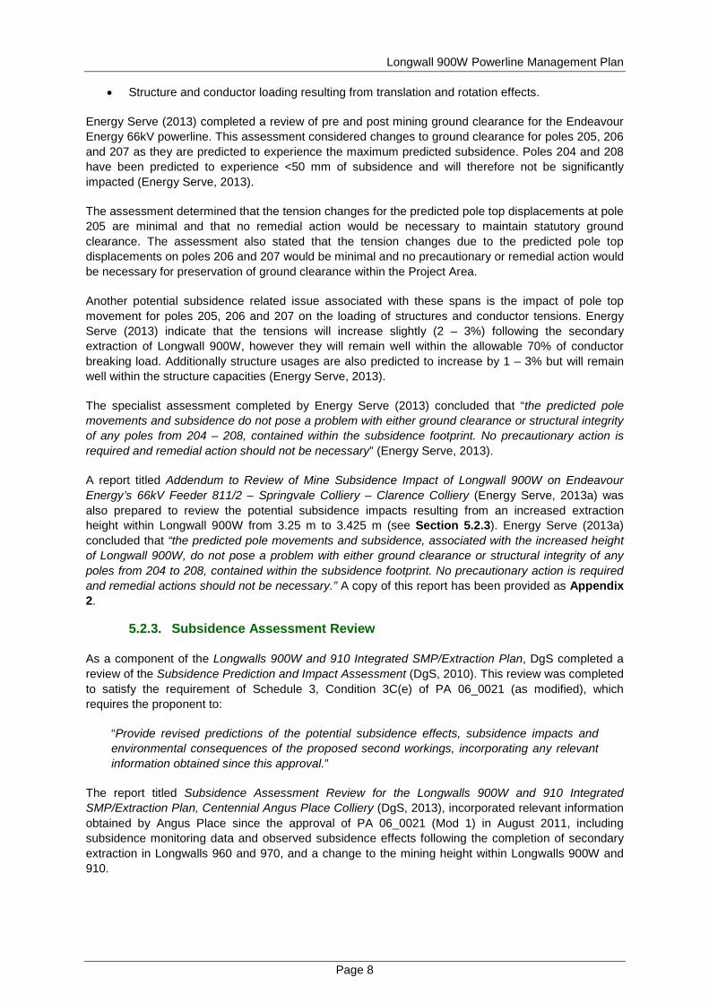
Longwall 900W Powerline Management Plan
Page 10
Risk Current Controls Risk Ranking Recommended Controls
There is a risk to Angus Place from Damage to Endeavour Energy powerlines Caused by Subsidence Resulting in Financial liability
Consultation with Endeavour Energy
Low
A centreline will be installed prior Longwall 900W secondary extraction
Subsidence assessment includes predictions for each asset
Develop Powerlines Management Plan in consultation with Endeavour Energy
Locations of power infrastructure identified
Engage specialist engineering consultant to develop impact assessment on powerlines and identify appropriate mitigation methods
No oil bearing assets in application area
Visual inspection of powerlines to be included in development of Powerlines Management System
Subsidence monitoring regime following powerlines across Longwall 900W block
There is a risk to Angus Place from Damage to Endeavour Energy powerlines Caused by Subsidence Resulting in Bushfires
Subsidence assessment includes predictions for each asset
Low
Engage specialist engineering consultant to develop impact assessment on powerlines and identify appropriate mitigation methods
Locations of power infrastructure identified
Subsidence monitoring regime following powerlines across Longwall 900W block
Consultation with Endeavour Energy
Review Angus Place Bushfire Management Plan after Powerlines Management Plan and engineering consultant plans have been completed
Angus Place Bush Fire Management Plan
Visual inspection of powerlines to be included in development of Powerlines Management System
Endeavour Energys vegetation controlling systems
No oil bearing assets in application area
To further mitigate subsidence-related risks to the 66kV powerline Angus Place has implemented the lsquorecommended controlsrsquo as outlined in Table 5 including the preparation of this Powerlines Management Plan in consultation with Endeavour Energy To mitigate the risk of subsidence exacerbating erosion along the powerline corridor Angus Place will undertake the management measures outlined in Section 8
Angus Place has also developed a powerline monitoring program as detailed in Section 9 This program includes the installation of subsidence survey lines and visual inspections as per the recommendations of the SMP Risk Assessment Energy Serve were engaged to prepare a specialist impact assessment entitled the Review of Mine Subsidence Impact of Longwall 900W on Endeavour Energyrsquos 66kV Feeder 8112 ndash Springvale Colliery ndash Clarence Colliery (Energy Serve 2013) An additional assessment was undertaken which was titled Addendum to Review of Mine Subsidence Impact of Longwall 900W on Endeavour Energyrsquos 66kV Feeder 8112 ndash Springvale Colliery ndash
Longwall 900W Powerline Management Plan
Page 11
Clarence Colliery (Energy Serve 2013a) to assess the potential subsidence impacts associated with an increased mining height within Longwall 900W from 325 m to 3425 m A summary of the findings from these assessments has been outlined in Section 522 and copies of the reports have been provided as Appendices 1 and 2
Angus Place will undertake a review of the Bushfire Management Plan prior to the commencement of secondary extraction in Longwall 900W
Longwall 900W Powerline Management Plan
Page 12
7 PERFORMANCE MEASURES AND INDICATORS
71 Performance Measures
Subsidence impact performance measures are specified in Schedule 3 Condition 3A of PA 06_0021 (as modified) The performance measures specifically relating to the 66kV transmission line include
bull That the powerline is always safe and serviceable and bull Damage that does not affect safety or serviceability must be fully repairable and must be fully
repaired unless the owner agrees otherwise in writing
72 Performance Indicators
To establish compliance with the performance measures as outlined in Section 71 Angus Place has developed a monitoring program This monitoring program (see Section 9) will be used to demonstrate that the environmental performance satisfies the following performance indicators
bull Visual inspections of the 66kV powerline to identify that there are no obvious visual abnormalities and
bull Survey monitoring within the Project Area identifies that subsidence parameters (subsidence tilt strain and angle of draw) are within the limits of the prediction model
8 MANAGEMENT MEASURES
As per the recommendations of the Subsidence Prediction and Impact Assessment (DgS 2010) Review of Mine Subsidence Impact Of Longwall 900W on Endeavour Energyrsquos 66kV Feeder 8112 ndash Springvale Colliery ndash Clarence Colliery (Energy Serve 2013) and the SMP Risk Assessment the management and mitigation measures outlined in Sections 81 and 82 will be implemented by Angus Place during the secondary extraction of Longwall 900W
81 Endeavour Energy 66kV Powerline
As specified in Sections 521 and 523 the predicted subsidence and pole movements do not pose a problem with either ground clearance or structural integrity to any poles within the Project Area (Energy Serve 2013) Additionally the specialist assessment prepared by Energy Serve (2013) concluded that ldquono precautionary action is required and remedial action should not be necessaryrdquo Although no precautionary or remedial actions are expected to be required Energy Serve (2013) recommend that the movement of power poles and the consequent action of the spans should be observed throughout the proposed secondary extraction and subsidence Accordingly Angus Place propose to implement a detailed monitoring program for the Endeavour Energy 66kV powerline This program will be undertaken to confirm that the observed subsidence parameters are consistent with the predictions of DgS (2010) and Energy Serve (2013) This will be achieved by implementing the following measures
bull Implementing a subsidence monitoring program for the 66kV powerline as detailed in Section 92 that will include
o Surveying of the proposed centreline (the lsquoI Linersquo) that will be installed at the commencing end of Longwall 900W
o Surveying of fixed survey points (reflectors) near the top and base of each power pole associated with the Project Area (poles 201 ndash 211)
bull Implementing a visual inspection program that will include the use of photo monitoring (see Section 92) In the event that any obvious abnormalities are identified during an inspection a survey will be triggered
Longwall 900W Powerline Management Plan
Page 13
bull Angus Place will prepare and distribute the results of each survey to relevant stakeholders (see Section 14)
bull In the unlikely event that subsidence monitoring andor visual inspections identify that a performance indicator has been exceeded Angus Place will implement the contingency measures as detailed in the Trigger Action Response Plan (see Table 6) and
bull Following completion of subsidence in the vicinity of the 66kV powerline the final sags in the spans will be assessed to determine if they need to be corrected
82 Existing Erosion and Sedimentation Along Powerline Corridor
As outlined in Section 6 Angus Place completed an SMP Risk Assessment at the commencement of the Angus Place Longwalls 900W and 910 Integrated SMPExtraction Plan to identify potential subsidence related hazards that may result from the secondary extraction of longwall panels within the Project Area A risk that was identified during the risk assessment and relevant to the preparation of this Powerline Management Plan is the ldquopotential for subsidence to exacerbate existing erosion along the powerline easementrdquo Although the predicted maximum consequence for subsidence related erosion along the powerline corridor was ranked as being insignificant this risk was assessed as being lsquomoderatersquo as a result of the expected likelihood of this erosion occurring (ranked as probable)
A number of lsquorecommended controlsrsquo were identified during the SMP Risk Assessment that could be used to mitigate potential subsidence related risks As outlined in Table 5 a recommendation was made to mitigate the exacerbation of existing erosion along the powerline corridor by Angus Place which outlined a commitment to ldquoinvestigate monitoring and remedial requirements with Endeavour Energyrdquo Prior to the commencement of secondary extraction within Longwall 900W and at the convenience of Endeavour Energy Angus Place propose to undertake a joint inspection of the 66kV powerline corridor to assess the condition of the existing erosion Duringfollowing this inspection both companies can commence discussions with regard to an agreeable management approach
9 MONITORING PROGRAM
91 Baseline Monitoring
Baseline monitoring of the land within the Project Area will be undertaken prior to the commencement of secondary extraction within Longwall 900W Baseline data will be obtained by Angus Place using a combination of the following methods
bull Installation of a subsidence monitoring line (the ldquoIrdquo Line) that will be used to monitor the angle of draw subsidence tilt and strain The line will be surveyed prior to secondary extraction in Longwall 900W to establish pre-mining data
bull Installation of fixed survey points (reflectors) near the top and base of each power pole These points will be used to monitor subsidence relative pole movement change in sagtensions and variation of anchorage conditions These points will be surveyed twice prior to secondary extraction within Longwall 900W to establish reliable pre-mining data and
bull A visual inspection program will be undertaken by Angus Place that includes the use of photo monitoring points prior to the commencement of secondary extraction in Longwall 900W to establish the pre-mining condition of the Endeavour Energy 66kV powerline
92 Monitoring Subsidence Impacts
The Endeavour Energy 66kV powerline will be monitored pre and post mining for evidence of any subsidence related impacts Table 6 provides a summary of the subsidence monitoring program that will be undertaken to manage this feature Figure 3 illustrates the location of proposed subsidence monitoring that is relevant to the 66kV powerline Additional detail pertaining to subsidence monitoring
Longwall 900W Powerline Management Plan
Page 14
methodology relevant to the Project Area can be found in the Longwalls 900W and 910 Subsidence Monitoring and Reporting Program
Table 6 Subsidence Monitoring Program
Monitoring Method Parameter Frequency
Subsidence survey line Subsidence tilt strain and angle of draw
Prior and post secondary extraction within Longwall 900W
Fixed survey points
Subsidence relative pole movement1 change in sagtensions2 and variation of anchorage conditions3
Powerline monitoring will be undertaken at the following frequency
bull Twice prior to commencement of secondary extraction in Longwall 900W
bull When secondary extraction of Longwall 900W reaches the following chainages CH2000 CH1890 CH1820 CH1730 CH1530 (see Figure 3)
bull Three months after CH1530 survey at the completion of secondary extraction within Longwall 900W and
bull Six monthly until no significant4 difference between successive surveys is detected
Visual inspections (including photo monitoring)
Presence or absence of visual abnormalities
Photo monitoring and visual inspections of the powerline will be undertaken at the following frequency
bull Prior to the commencement of secondary extraction in Longwall 900W
bull Weekly from commencement of secondary extraction until Longwall 900W reaches chainage CH1450 (when all poles within the Project Area have been undermined)
bull Monthly for three months bull Bi-monthly for two inspections and bull Tri-monthly for three inspections
1 The relative movement ie lean will be determined through a comparison of the bearing and distance (horizontal projection) between the top and bottom reflector from one survey to the next Total lean will be referenced against the baseline survey bearing and distance 2 A comparison between the 3D coordinates of the reflector at the top of one pole to the next will determine a baseline distance between each pole at the level of the wire attachment point A change in distance between the tops of the poles will indicate a change in sag and tension of the wires between the two relevant power poles 3 Variations to anchorage conditions will be measured at a specific point placed on each anchor point 3D coordinates will be determined for the mark and its movement relative to the reflector at the top of the pole calculated and compared to the baseline survey The change in slope distance between the anchor point and the top of the pole should indicate any change in anchor tension 4 Significant is defined as being 15 times the difference in results from the two baseline surveys
Longwall 900W Powerline Management Plan
Page 15
93 Monitoring Environmental Consequences
Angus Place will implement the monitoring program as specified in Table 6 to monitor the development of predicted subsidence associated with the Endeavour Energy 66kV powerline (see Section 52) A contingency plan has been developed as a component of this Powerline Management Plan to outline management measures that will be implemented in the event that predicted environmental consequences are exceeded (see Section 12)
94 Success of Remediation Measures
In the event that remediation of the 66kV powerline is required Angus Place will undertake rehabilitation in consultation with relevant NSW Government Agencies Endeavour Energy and the Forestry Corporation of NSW (FCNSW) During consultation and prior to implementation of any remedial measures Angus Place will determine the ongoing monitoring requirements
9
10
11
12
13
14
15
16
17
19
31
34
35
36
37
38
18
21
20
32
33
Proposed Powerline Monitoring
Proposed Powerline Monitoring
LONG
WAL
L 900
WES
T
LONGWALL 970
LONGWALL 980
Prop
osed
I L
ine
Base Plan Data Source Centennial Angus Place Pty Ltd
FIGURE 3
Longwall 900W Powerline Management Plan
Powerline Monitoring
To be printed A4
VAngus PlaceCCC07-007FiguresFinalCADLongwall 900W Powerline Management PlanFg3_CCC07-007_Powerlines Monitoring Line_130809dwg
0 400m200
Scale 1 10 000
LEGEND
S
W
N
E
Colliery Holding Boundary
Angus Place Workings
Springvale Workings
Proposed Powerline Monitoring
Proposed Subsidence Line
Longwall 900W Powerline Management Plan
Page 17
10 CONSULTATION
In accordance with Schedule 3 Condition 3C(g) of PA 06_0021 (as modified) this Powerline Management Plan was provided to Endeavour Energy as part of the consultation process on 28 August 2013 No comments have been received from Endeavour Energy regarding this Powerline Management Plan
In November 2013 this Powerline Management Plan was updated to include the relevant findings as presented in the Addendum to Review of Mine Subsidence Impact of Longwall 900W on Endeavour Energyrsquos 66kV Feeder 8112 ndash Springvale Colliery ndash Clarence Colliery (Energy Serve 2013a) and the Subsidence Assessment Review for the Longwalls 900W and 910 Integrated SMPExtraction Plan Centennial Angus Place Colliery (DgS 2013) (see Sections 522 and 523) This plan was subsequently re-submitted to Endeavour Energy for consultation on 15 November 2013
Evidence of the consultation undertaken during the preparation of this Powerline Management Plan has been provided as Appendix 3
11 ADAPTIVE MANAGEMENT
Angus Place has developed an adaptive management approach that is designed to avoid repetition of any unpredicted subsidence impacts andor environmental consequences This approach will include the monitoring and periodic evaluation of environmental consequences against the performance indicators defined in Section 72 the implementation of the contingency plan (see Section 12) in the event that a performance indicator is exceeded and the review of this Powerline Management Plan as necessary (see Section 15)
12 CONTINGENCY PLAN
A TARP has been developed using the performance indicators for the 66kV powerline as outlined in Section 72 In the event that subsidence monitoring andor visual inspections identify that a performance indicator has been exceeded Angus Place will implement the contingency measures as detailed in the TARP (see Table 7)
Longwall 900W Powerline Management Plan
Page 18
Table 7 Trigger Action Response Plan for Endeavour Energy 66kV Powerline Aspect
Category Key Element
Trigger Response
Condition Green Condition Amber Condition Red
Endeavour Energy 66kV Powerline
Subsidence
Trigger Survey monitoring along the lsquoI Linersquo identifies that measured subsidence parameters (subsidence tilt and strain) are less than the limits specified by the prediction model (DgS 2010)
Survey monitoring along the lsquoI Linersquo identifies that measured subsidence parameters (subsidence tilt and strain) are up to but do not exceed the limits of the prediction model (DgS 2010)
Survey monitoring along the lsquoI Linersquo identifies that measured subsidence parameters (subsidence tilt and strain) exceed the limits of the prediction model (DgS 2010)
Response No response required Continue monitoring program No response required Continue monitoring program
If subsidence associated with the powerline exceeds the limits of the prediction model notify the Director-General of DPampI DTIRIS Endeavour Energy and the FCNSW of exceedance of subsidence predictions Investigate exceedance of subsidence prediction model Identify and implement remedial actions in consultation with relevant stakeholders if necessary (eg undertake review of Powerline Management Plan)
Trigger
Survey monitoring of fixed survey points (reflectors) on relevant power poles identify that measured subsidence andor relative pole movements are less than the limits specified by the prediction models (DgS 2010 Energy Serve 2013)
Survey monitoring of fixed survey points (reflectors) on relevant power poles identify that measured subsidence andor relative pole movements are up to but do not exceed the limits of the prediction models (DgS 2010 Energy Serve 2013)
Survey monitoring of fixed survey points (reflectors) on relevant power poles identify that measured subsidence andor relative pole movements exceed the limits of the prediction models (DgS 2010 Energy Serve 2013)
Response No response required Continue monitoring program No response required Continue monitoring program
If subsidence associated with the powerline exceeds the limits of the prediction model notify the Director-General of DPampI DTIRIS Endeavour Energy and the FCNSW of exceedance of subsidence predictions Investigate exceedance of subsidence prediction model Identify and implement remedial actions in consultation with relevant stakeholders if necessary (eg undertake review of Powerline Management Plan)
Evidence of damage
Trigger Visual inspections of the site identify that there is no evidence of abnormalities to the powerline
Visual inspections identify potential evidence of abnormalities to the powerline ie changes to powerline ground clearance or pole verticality
Visual inspections identify evidence of abnormalities to the powerline ie obvious changes to powerline ground clearance or pole verticality
Response No response required Continue monitoring program
Review previous photographic evidence to identify if there have been visual changes to the powerline since the commencement of secondary extraction in Longwall 900W ie pole verticality If the review of photographic evidence identifies that there are no abnormalities continue monitoring program If abnormalities are identified undertake survey monitoring to identify if measured subsidence andor relative pole movements are within the limits of the prediction models (DgS 2010 Energy Serve 2013) If measured subsidence andor relative pole movements are within the limits of the prediction models report the results to the stakeholders specified in Table 9 Continue monitoring program If measured subsidence andor relative pole movements are beyond the limits of the prediction models undertake management as outlined for Condition Red responses
Undertake survey monitoring to identify if measured subsidence andor relative pole movements are within the limits of the prediction models (DgS 2010 Energy Serve 2013) If measured subsidence andor relative pole movements are within the limits of the prediction models report the results to the stakeholders specified in Table 9 Continue monitoring program If measured subsidence andor relative pole movements are beyond the limits of the prediction models notify the Director-General of DPampI DTIRIS Endeavour Energy and the FCNSW of exceedance of subsidence predictions Erect warning signs and danger tape in immediate area Investigate exceedance of subsidence prediction model Identify and implement remedial actions in consultation with relevant stakeholders if necessary
Longwall 900W Powerline Management Plan
Page 19
13 ROLES AND RESPONSIBILITIES
The responsibility for implementation monitoring and review of the Powerline Management Plan lies with the Environment and Community Coordinator The ultimate responsibility for the implementation of the Powerline Management Plan lies with the Mine Manager who shall make appropriate resources available The roles and responsibilities for this Powerline Management Plan are outlined in Table 8
Table 8 Key Personnel and Accountabilities Position Responsibility
Mine Manager bull Ensuring that sufficient resources are available to implement and execute the
requirements of this Plan and bull Reporting triggersnon-conformances to external stakeholders
Environment and Community Coordinator
Implementation monitoring and review of this plan including bull The carrying out of inspections
bull The installation and maintenance of signage
bull Reporting triggersnon-conformances internally to the Mine Manager as appropriate
bull Consulting with Endeavour Energy regarding any serviceability issues arising from subsidence
bull Consultation during the review process with relevant stakeholders and distributing this Powerline Management Plan
bull Coordinating any remediation work as required in consultation with Endeavour Energy and the FCNSW
bull Co-ordinating the generation and submission of formal reporting requirements outlined in this Plan (eg End of Panel Reports and the Annual Environmental Management Report) and
bull Reviewing this Powerline Management Plan
Endeavour Energy
bull Undertake inspections as required with Environment and Community Coordinator and
bull Determine appropriate remedial measures in conjunction with Environment and Community Coordinator if required
14 REPORTING
In accordance with the requirements of the Draft Guidelines for the Preparation of Extraction Plans (DPampI 2012) Angus Place will submit the following reports to the DPampI and DTIRIS during the secondary extraction of Longwalls 900W and 910
bull Bi-monthly Subsidence Impact Reports - These reports will be submitted following the regular monthly inspections if any new subsidence impacts are identified and
bull Six-monthly Environmental Monitoring Report - This report will include
minus a comprehensive summary of all impacts including a revised characterisation according to the relevant TARP and any proposed actions resulting from the relevant TARP (see Section 12)
minus an assessment of compliance with relevant performance indicators (see Section 72) and
Longwall 900W Powerline Management Plan
Page 20
minus a comprehensive summary of all quantitative and qualitative environmental monitoring results
The Annual Environmental Management Report (AEMR)Annual Review will be made available on the Centennial Coal website and will include subsidence monitoring results performance against subsidence predictions and identification of any subsidence related environmental impacts identified during the reporting period
In accordance with the requirements of Schedule 5 Condition 6 of PA 06_0021 (as modified) Angus Place will notify the Director-General of DPampI Endeavour Energy and any other relevant agencies of any powerline management related incident resulting from the extraction of Longwalls 900W and 910 as soon as practicable after becoming aware of the incident Within seven days of the incident the Proponent shall provide the Director-General of DPampI and any relevant agencies with a detailed report on the incident
Angus Place will also prepare an End of Panel Report to encompass all environmental and subsidence monitoring including a comparison of actual impacts with predicted subsidence impacts This report will be submitted to DTIRIS within three months of secondary extraction being completed in each longwall panel
Following the completion of each survey as outlined in Table 6 survey results will be compiled into a report that will be distributed to representatives of Endeavour Energy Energy Serve and Angus Place Contact details for the relevant representatives have been provided in Table 9
Table 9 Primary Contacts
Company Contact Title Contact Details
Endeavour Energy Rod Joyce Operational Planning
T 02 9853 6823
E RodJoyceendeavourenergycomau
Energy Serve Kevin Rugg Principal Consultant T 02 6885 3224
E kevinenergyservecomau
Angus Place
Alan Mellor Mine Surveyor T 02 6354 8702
E AlanMellorcentennialcoalcomau
Natalie Conroy Environment and Community Coordinator
T 02 6354 8938
E NatalieConroycentennialcoalcomau
15 REVIEW
This Powerline Management Plan will be reviewed in the event that the following occur
bull Endeavour Energy raise issues that necessitate a review bull There are changes to the management requirements (eg changes to related approvals) bull Where unpredicted impacts or consequences have required implementation of contingency
actions under this plan or bull Monitoring incident or audit processes demonstrate that a review is warranted
Any amendments to the Powerline Management Plan will be undertaken in consultation with Endeavour Energy and relevant stakeholders Following any changes a copy of the amended Powerline Management Plan will be forwarded to the Executive Director Mineral Resources of DTIRIS and the Director-General of the DPampI for approval
Longwall 900W Powerline Management Plan
Page 21
16 REFERENCES
Centennial Coal (2008) Centennial Coal Risk Management Standard (Management Standard ndash 004)
DgS (2010) Subsidence Prediction and Impact Assessment Report no ANP_0021
DgS (2013) Subsidence Assessment Review for the Longwalls 900W and 910 Integrated SMPExtraction Plan Centennial Angus Place Colliery Report No ANP-0027
Department of Mineral Resources (2003) Guideline for Applications for Subsidence Management Approvals
DPampI (2012) Draft Guidelines for the Preparation of Extraction Plans
EnergyServe (2013) Review of Mine Subsidence Impact of Longwall 900W on Endeavour Energyrsquos 66kV Feeder 8112 ndash Springvale Colliery ndash Clarence Colliery
Energy Serve (2013a) Addendum to Review of Mine Subsidence Impact of Longwall 900W on Endeavour Energyrsquos 66kV Feeder 8112 ndash Springvale Colliery ndash Clarence Colliery
RPS (2010) Angus Place Colliery NSW Modification of Project Approval 06_0021 under Section 75W Part 3A
Longwall 900W Powerline Management Plan
This page has been intentionally left blank
Appendix 1 Review of M
ine Subsidence Impact of
Longwall 900W
on Endeavour Energyrsquos 66kV Feeder
Jemtom Pty Ltd ta Energy Serve bull ABN 36 078 771 650 Suite 1 Level 1 139 Macquarie Street Dubbo NSW 2830
Tel (02) 6885 3224 bull Fax (02) 6885 3210 bull Mobile 0427 853 224
CENTENNIAL COAL
Angus Place Colliery Wolgan Road Lidsdale
Review of Mine Subsidence Impact
Of Longwall 900W on Endeavour Energyrsquos
66kV Feeder 8112 ndash Springvale Colliery-Clarence Colliery
2 May 2013
Amendment A
Power System Engineering amp
Energy Advisory Services
Page 2 May 2 2013
Disclaimer Due to the unpredictable nature of mine subsidence Energy Serve is unable to accurately determine the behaviour of powerlines under the influence of such movements This report and the recommendations contained herein are based on the information provided and are intended to be sufficiently conservative to cater for the range of expected movements
It is not practical to predict the dynamic nature of the subsidence or all the possible intermediate outcomes hence it is recommended that regular inspection and monitoring is undertaken during and following longwall mining in the vicinity of the powerlines in question
Energy Serve will not be liable or responsible for any damage loss of revenue loss of production or unsafe conditions caused by mine subsidence on powerlines
Contents
Amendments 2 Background 3 Methodology 3 Predicted Subsidence at Pole Locations 4 Results 4
Existing Ground Clearance Issue outside Subsidence Area 4 Ground Clearance 5 Pole amp Conductor Loading 5
Summary 7 Recommendations 7 Endeavour Energy Consultation amp Approval 7 Appendix A ndash 66kV Feeder relative to Longwall 900 West (LW900W) 8 Appendix B ndash Plan amp Profile ndash Pre-subsidence 9 Appendix C ndash Plan amp Profile ndash Post-subsidence 12 Appendix D ndash Section Usage Report ndash Existing 15 Appendix E ndash Section Usage Report ndash Post-subsidence 17 Appendix F ndash Structure Usage Report ndash Existing 19 Appendix G ndash Structure Usage Report ndash Post-subsidence 24 Appendix H ndash Endeavour Energy ndash David Mate ndash Email 25 March 2013 29
Amendments
Draft Draft for client review 01112012
Final Draft Final Draft for client review 25012013
Amendment A Endeavour Energy consultation included 01052013
Page 3 May 2 2013
Background
Energy Serve has been commissioned by GSS Environmental on behalf of Centennial Coal ndash Angus Place Colliery to review the impact of the proposed mining of the Longwall 900 West (900W) on Endeavour Energyrsquos 66kV 8112 Feeder
This feeder is generally 66kV delta suspension construction however there are four in-line or angle strain structures within the six spans potentially impacted by the predicted subsidence
The suspension structures have a significant capacity to absorb the pole movements A potential subsidence related issue can be the strain structures subject to longitudinal movement as this can have a significant effect on conductor tensions and thereby ground clearances
Appendix A shows the 8112 Feeder in relation to the proposed Longwall 900W and other workings associated with the Centennial Coal - Angus Place Colliery
The data used to conduct this review included
bull Centreline survey of the existing natural surface conducted by Cramer Elliston amp Hayes (Lithgow) Surveyors
bull Record of structure details and photos collected by Cramer Elliston amp Hayes and bull Subsidence report by Ditton Geotechnical Services Pty Ltd (DgS) for Longwalls 910 amp 900
West including predicted subsidence contours plus surface translation and rotations at each structure
Methodology
The centreline survey data was imported into PLSCADD to create an existing surface profile PLSCADD was then also used to modify the centreline data within the 900W subsidence contours to create a post-subsidence centreline The two sets of data were used to create pre- and post-subsidence profiles under the powerline
The impact of longwall mining includes not just vertical subsidence at the surface Structures at or near the surface also experience translational and rotational movements which may be transient in nature as the longwall mining progresses past the point of concern However some residual translation and rotation will remain depending on the relative position of the pole in relation to the direction and sides of the longwall cut
Pole structures are particularly sensitive to rotational impacts due to the relative height of the pole above ground What seems like a minimal rotation at ground level will get multiplied into significant movements at the pole top These movements are critical to pole top and conductor loadings as well as inter-circuit clearances A small pole top movement can result in substantial conductor tension and load changes
PLSCADD has been used to model the following
bull Before amp after ground clearance for statutory clearance and where practical intermediate scenarios where the subsidence transitions through the site and
bull Structure and conductor loading due to the abovementioned translation and rotation effects
The PLSCADD powerline software has the capability of modelling the impact on installed systems The effect of pole movement andor splicing in or cutting out of conductor can be modelled with a high degree of confidence
Page 4 May 2 2013
Predicted Subsidence at Pole Locations
The following table of predicted subsidence translation and rotations were supplied by DgS See Table 12 p37 of DgS Report No ANP-0021
Pole ID
Final Subsidence due to 900W
(mm)
Final Tilt Towards
Longwall due to 900W (mmm)
Final Tilt Along Axis of Longwall due
to 900W (mmm)
Predicted Horizontal Movement Towards
Longwall due to 900W (mm)
Predicted Horizontal
Movement Along Main Axis of
Longwall due to 900W (mm)
201 0 0 0 0 0 202 0 0 0 0 0 203 0 0 0 0 0 204 30 03 03 5 5 205 720 83 65 133 103 206 1000 55 -20 -88 -31 207 380 74 -57 -118 -91 208 40 04 -02 -6 -4 209 0 0 0 0 0 210 0 0 0 0 0 211 0 0 0 0 0
Results
The maximum predicted surface subsidence to be experienced by the 66kV feeder is 1000mm at Pole 206 Subsidence is predicted to extend over a total route length of 970 metres but will exceed 200 mm over a distance of 360 metres only impacting Poles 205-206-207
Appendix B contains Plan amp Profile Sheets showing the existing mains at a maximum operating temperature of 85degC and the pre-subsidence ground profile
Existing Ground Clearance Issue outside Subsidence Area
It is apparent that there is more than enough ground clearance throughout the subsidence area to allow for the predicted vertical subsidence
However in the span between Poles 209 amp 210 it is evident that there is insufficient clearance in the vicinity of Pole 210
Appendix A shows that Pole 210 is not within the predicted subsidence area for Longwall 900W and has not been impacted by subsidence due to other mine workings It is located outside any past or future subsidence area
Endeavour Energy may wish to review the attached profile (Appendix B) and consider taking remedial action The existing lines do not meet statutory clearance at 65degC
Page 5 May 2 2013
Ground Clearance
It can be seen that the maximum projected subsidence occurs in the vicinity of poles 205 206 amp 207 with up to 1000mm vertical displacement predicted at Pole 206 and 720mm at Pole 205
The excess ground clearance in these spans is more than sufficient to cater for the progressive subsidence impacting each pole It is likely in any case that pole 206 and the surface between 205 amp 206 will commence subsiding before pole 205 reaches its final level
The predicted subsidence at poles 204 amp 208 are less than 50mm and will therefore not be significantly impacted
A potential subsidence related issue associated with the 66kV powerline may be conductor tension changes due to pole head movement particularly at pole 205 due to its being located on the side of the subsidence area and predicted to experience the highest horizontal displacement and tilt
Appendix C indicates that the tension changes for the predicted pole top displacements at pole 205 are minimal and that no remedial action appears to be necessary to maintain statutory ground clearance
Figures 1 2 amp 3 show the pole tops for structures 205 206 amp 207 respectively
Likewise the tension changes due to the predicted pole top displacements on poles 206 amp 207 are also minimal and no precautionary or remedial action is necessary for preservation of ground clearance within the 900W subsidence footprint
Figure 1 - Structure 205 pole top
Pole amp Conductor Loading
Another potential issue with these spans is the impact of pole top movement of poles 205 206 amp 207 on the loading of structures and conductor tensions
Page 6 May 2 2013
Appendices D amp E include Pre amp Post-subsidence Section Usage reports The tensions increase slightly (2-3) but remain well within the allowable 70 of conductor breaking load
Appendices F amp G include Pre amp Post-subsidence Structure Usage reports Structure usages also increase slightly (1-3) but remain well within structure capacities Maximum usage is lt 75
Figure 2 - Structure 206 pole top
Figure 3 - Structure 207 pole top
Page 7 May 2 2013
Summary
The check survey has indicated an existing ground clearance issue between poles 209 amp 210 This span is outside the current and any previous subsidence areas Endeavour Energy may wish to follow this up
The predicted pole movements and subsidence do not pose a problem with either ground clearance or structural integrity of any of the poles from 204 to 208 contained within the subsidence footprint No precautionary action is required and remedial action should not be necessary
Recommendations
It is not recommended that any precautionary actions be taken
The movement of these poles and the consequent action of the spans should be observed throughout the proposed mining and subsidence in order to validate the predictions and ensure clearances have been maintained at all times and structure loadings have not been exceeded
Following completion of the subsidence in this vicinity the final sags in the spans should be assessed as to whether they need to be corrected
In any case the powerline should be closely monitored throughout the mining subsidence process to ensure no unexpected hazards arise and statutory clearances are maintained
Endeavour Energy Consultation amp Approval
Following review and endorsement by Centennial Coal this report was submitted to Endeavour Energy (EE) for consideration It was initially uncertain as to who within EE would provide the final approval on behalf of EE
The identification of the existing clearance issue caused an immediate reaction and action is underway to address this problem
Once the appropriate officer was identified the report was assessed by David Mate and approved by email A copy of the email approval and precedent trail of emails is included in Appendix H
No remedial action is required
Monitoring of the powerline is recommended throughout the mining subsidence process as detailed above
Kevin Rugg
Principal Consultant
Jemtom Pty Ltd ta Energy Serve bull ABN 36 078 771 650 Suite 1 Level 1 139 Macquarie Street Dubbo NSW 2830
Tel (02) 6885 3224 bull Fax (02) 6885 3210 bull Mobile 0427 853 224
Appendix A ndash 66kV Feeder relative to Longwall 900 West (LW900W)
Jemtom Pty Ltd ta Energy Serve bull ABN 36 078 771 650 Suite 1 Level 1 139 Macquarie Street Dubbo NSW 2830
Tel (02) 6885 3224 bull Fax (02) 6885 3210 bull Mobile 0427 853 224
Appendix B ndash Plan amp Profile ndash Pre-subsidence
PLS
-CA
DD
Dra
win
g
-100
0
100
200
300
400
500
600
700
800
900
1000
1100
1115
1120
1125
1130
1135
1140
1145
1150
1155
1160
1165
1170
1175
1180
1185
1190
1195
1200
1205
1210
1215
1115
1120
1125
1130
1135
1140
1145
1150
1155
1160
1165
1170
1175
1180
1185
1190
1195
1200
1205
1210
1215
PI 0deg0000
PI 41deg0000
PI -14deg4800
PI -16deg5400
19912 1045 Sunny 13C 02 ms
211 211_17-201pol
210 210_17-202pol
209 209_215-203pol
208 208_185-204pol
207 207_17-205pol
206 206_185-206pol
1341
3829
2207
2417
1227 9700
m
Ext
ent of su
bsi
dence
zone
66kV
PB-206
PB-207
PB-208
PB-209
PB-21
PB-211
14
15
16
17
211
210
209
208
207
206
PI 000
0deg0000
PI 13415 41deg0000
517034deg4800
110218
16deg5400
AN
GU
S P
L 6
6 2
0121101
Exi
stin
g11
12
012
Page 1
2V
ert
S
cale
Horiz
Sca
le
100
m
500
m
North
PLS
-CA
DD
Dra
win
g
1100
1200
1300
1400
1500
1600
1700
1800
1900
2000
1125
1130
1135
1140
1145
1150
1155
1160
1165
1170
1175
1180
1185
1190
1195
1200
1205
1210
1215
1220
1225
1125
1130
1135
1140
1145
1150
1155
1160
1165
1170
1175
1180
1185
1190
1195
1200
1205
1210
1215
1220
1225
PI 0deg0000
206 206_185-206pol
205 205_185-207pol
204 204_17-208pol
203 203_185-209pol
202 202_17-2010pol
201 201_17-2011pol
1124
2293
1521
1266
2347
Ext
ent of su
bsi
dence
zone
PO
WE
RL
I NE
VPB-2
03
PB-2
04
PB-2
05
PB-2
0607
PPB-2
00
PB20
1
PB-2
0235
36
37
38
206
205
204
203
202
201
PI 110218-16deg5400
PI 1957190deg0000
AN
GU
S P
L 6
6 2
0121101
Exi
stin
g11
12
012
Page 2
2V
ert
S
cale
Horiz
Sca
le
100
m
500
m
Nor
th
Page 12 May 2 2013
Appendix C ndash Plan amp Profile ndash Post-subsidence
PLS
-CA
DD
Dra
win
g
-100
0
100
200
300
400
500
600
700
800
900
1000
1100
1115
1120
1125
1130
1135
1140
1145
1150
1155
1160
1165
1170
1175
1180
1185
1190
1195
1200
1205
1210
1215
1115
1120
1125
1130
1135
1140
1145
1150
1155
1160
1165
1170
1175
1180
1185
1190
1195
1200
1205
1210
1215
PI 0deg0000
PI 41deg0000
PI -14deg4800
PI -16deg5400
19912 1045 Sunny 13C 02 ms
211 211_17-201pol
210 210_17-202pol
209 209_215-203pol
208 208_185-204pol
207 207_17-205pol
206 206_185-206pol
1341
3829
2207
2417
1227 9700
m
Ext
ent of su
bsi
dence
zone
66kV
PB-206
PB-207
PB-208
PB-209
PB-21
PB-211
14
15
16
17
211
210
209
208
207
206
PI 000
0deg0000
PI 13415 41deg0000
517034deg4800
110218
16deg5400
AN
GU
S P
L 6
6 2
0121101
Post
subs
+ p
ole
mvt
s11
12
012
Page 1
2V
ert
S
cale
Horiz
Sca
le
100
m
500
m
North
PLS
-CA
DD
Dra
win
g
1100
1200
1300
1400
1500
1600
1700
1800
1900
2000
1125
1130
1135
1140
1145
1150
1155
1160
1165
1170
1175
1180
1185
1190
1195
1200
1205
1210
1215
1220
1225
1125
1130
1135
1140
1145
1150
1155
1160
1165
1170
1175
1180
1185
1190
1195
1200
1205
1210
1215
1220
1225
PI 0deg0000
206 206_185-206pol
205 205_185-20_subs7pol
204 204_17-208pol
203 203_185-209pol
202 202_17-2010pol
201 201_17-2011pol
1124
2293
1521
1266
2347
Ext
ent of su
bsi
dence
zone
PO
WE
RL
I NE
VPB-2
03
PB-2
04
PB-2
05
PB-2
0607
PPB-2
00
PB20
1
PB-2
0235
36
37
38
206
205
204
203
202
201
PI 110218-16deg5400
PI 1957190deg0000
AN
GU
S P
L 6
6 2
0121101
Post
subs
+ p
ole
mvt
s11
12
012
Page 2
2V
ert
S
cale
Horiz
Sca
le
100
m
500
m
Nor
th
Page 15 May 2 2013
Appendix D ndash Section Usage Report ndash Existing
Energy Serve
Page 11
PLS-CADD Version 1210x64 40015 PM Thursday 1 November 2012
Energy Serve
Project Name cuserskevin ruggdocumentsenergy servegss environmentalangus placeplsangus pl 66 20121101DON
Line Title Existing
Section Usage Report
Sec Cable From To Percent OK
No Name Str Str Usage NG
-----------------------------------
4 lemon 208 206 498 OK
5 lemon 206 204 489 OK
0 section violations OK
Check Section Summary
designates highest percent of allowable capacity
Sec Cable From To WC Weather Case Condition Allowable Actual Allowable Actual Allowable Actual of OK
No Name Str Str No Description of of Tension Tension Catenary Catenary Allowable or
No No Ultimate Ultimate (N) (N) (m) (m) Capacity NG
-------------------------------------------------------------------------------------------------------------------------------------
4 lemon 208 206 7 Limit 1000 Initial RS 700 348 313862 13423 498 OK
5 lemon 206 204 7 Limit 1000 Initial RS 700 343 308671 13242 489 OK
Page 17 May 2 2013
Appendix E ndash Section Usage Report ndash Post-subsidence
Energy Serve
Page 11
PLS-CADD Version 1210x64 35823 PM Thursday 1 November 2012
Energy Serve
Project Name cuserskevin ruggdocumentsenergy servegss environmentalangus placeplsangus pl 66 20121101DON
Line Title Post subs + pole mvts
Section Usage Report
Sec Cable From To Percent OK
No Name Str Str Usage NG
-----------------------------------
4 lemon 208 206 539 OK
5 lemon 206 204 519 OK
0 section violations OK
Check Section Summary
designates highest percent of allowable capacity
Sec Cable From To WC Weather Case Condition Allowable Actual Allowable Actual Allowable Actual of OK
No Name Str Str No Description of of Tension Tension Catenary Catenary Allowable or
No No Ultimate Ultimate (N) (N) (m) (m) Capacity NG
-------------------------------------------------------------------------------------------------------------------------------------
4 lemon 208 206 7 Limit 1000 Initial FE 700 378 340206 14565 539 OK
5 lemon 206 204 7 Limit 1000 Initial FE 700 363 327374 14052 519 OK
Page 19 May 2 2013
Appendix F ndash Structure Usage Report ndash Existing
Energy Serve
Page 14
PLS-CADD Version 1210x64 40113 PM Thursday 1 November 2012
Energy Serve
Project Name cuserskevin ruggdocumentsenergy servegss environmentalangus placeplsangus pl 66 20121101DON
Line Title Existing
Structure Locations and Usage Report
Structure Structure Station Line --Constraints--- Structure Insulator Minimum Pole OK
Number Name Angle Prohib Req Extra Strength Swing Required Tip or
Zone Pos Cost Usage Usage Vertical Deflection NG
Load Usage
(m) (deg) () () (Uplift) ()
---------------------------------------------------------------------------------------------------------
208 208_185-204pol 73777 000 0 737 00 OK OK
207 207_17-205pol 97945 000 0 531 320 OK OK
206 206_185-206pol 110218 -1690 Y 0 698 00 OK OK
205 205_185-207pol 121453 000 0 432 495 OK OK
204 204_17-208pol 144382 000 0 694 00 OK OK
0 structure violations 0 structure warnings OK
Energy Serve
Page 24
Multiple Structure Suspension Insulator Swing Angles and V-String Load Angles
Str Set Phase Swing Weather Wire Min Max Min Max of OK
Cond Case Condition Allowed Allowed Calc Calc Allowed
Description (deg) (deg) (deg) (deg) Swing
-----------------------------------------------------------------------------------------------------
207 3 1 1 Hot 85 Creep RS -900 900 -40 -40 45 OK
2 1 Hot 85 Creep RS -900 900 27 27 30 OK
3 1 Hot 85 Creep RS -900 900 -26 -26 29 OK
1 2 Swing 210 Initial RS -900 900 -166 57 184 OK
2 2 Swing 210 Initial RS -900 900 -78 153 170 OK
3 2 Swing 210 Initial RS -900 900 -142 72 158 OK
1 3 Swing 500 Initial RS -900 900 -288 188 320 OK
2 3 Swing 500 Initial RS -900 900 -212 280 311 OK
3 3 Swing 500 Initial RS -900 900 -261 197 290 OK
1 4 Cold 0 Initial RS -900 900 -59 -59 65 OK
2 4 Cold 0 Initial RS -900 900 40 40 45 OK
3 4 Cold 0 Initial RS -900 900 -37 -37 42 OK
205 1 1 Hot 85 Creep RS -900 900 -64 -64 71 OK
2 1 Hot 85 Creep RS -900 900 45 45 50 OK
3 1 Hot 85 Creep RS -900 900 -41 -41 46 OK
1 2 Swing 210 Initial RS -900 900 -276 81 307 OK
2 2 Swing 210 Initial RS -900 900 -123 263 293 OK
3 2 Swing 210 Initial RS -900 900 -231 107 257 OK
1 3 Swing 500 Initial RS -900 900 -444 295 493 OK
2 3 Swing 500 Initial RS -900 900 -343 446 495 OK
3 3 Swing 500 Initial RS -900 900 -400 301 444 OK
1 4 Cold 0 Initial RS -900 900 -115 -115 128 OK
2 4 Cold 0 Initial RS -900 900 85 85 94 OK
3 4 Cold 0 Initial RS -900 900 -72 -72 80 OK
Energy Serve
Page 34
Multiple Structure Minimum Vertical Load (Uplift) Summary
Str Set Phase Swing Weather Wire Min Vert Vert Vert OK
Cond Case Condition Req Load Load Load
Description Vert Wind Wind Margin
Load From From
Left Right
(N) (N) (N) (N)
-----------------------------------------------------------------------------------
207 3 1 1 Hot 85 Creep RS 0 2967 2967 2967 OK
2 1 Hot 85 Creep RS 0 2901 2901 2901 OK
3 1 Hot 85 Creep RS 0 3069 3069 3069 OK
1 2 Swing 210 Initial RS 0 3982 3982 3982 OK
2 2 Swing 210 Initial RS 0 3858 3858 3858 OK
3 2 Swing 210 Initial RS 0 4172 4172 4172 OK
1 3 Swing 500 Initial RS 0 4246 4246 4246 OK
2 3 Swing 500 Initial RS 0 4107 4107 4107 OK
3 3 Swing 500 Initial RS 0 4459 4459 4459 OK
1 4 Cold 0 Initial RS 0 4175 4175 4175 OK
2 4 Cold 0 Initial RS 0 4041 4041 4041 OK
3 4 Cold 0 Initial RS 0 4382 4382 4382 OK
205 1 1 Hot 85 Creep RS 0 1936 1936 1936 OK
2 1 Hot 85 Creep RS 0 1853 1853 1853 OK
3 1 Hot 85 Creep RS 0 2033 2033 2033 OK
1 2 Swing 210 Initial RS 0 2173 2173 2173 OK
2 2 Swing 210 Initial RS 0 2016 2016 2016 OK
3 2 Swing 210 Initial RS 0 2359 2359 2359 OK
1 3 Swing 500 Initial RS 0 2231 2231 2231 OK
2 3 Swing 500 Initial RS 0 2056 2056 2056 OK
3 3 Swing 500 Initial RS 0 2438 2438 2438 OK
1 4 Cold 0 Initial RS 0 2220 2220 2220 OK
2 4 Cold 0 Initial RS 0 2049 2049 2049 OK
3 4 Cold 0 Initial RS 0 2424 2424 2424 OK
Energy Serve
Page 44
Page 24 May 2 2013
Appendix G ndash Structure Usage Report ndash Post-subsidence
Energy Serve
Page 14
PLS-CADD Version 1210x64 40449 PM Thursday 1 November 2012
Energy Serve
Project Name cuserskevin ruggdocumentsenergy servegss environmentalangus placeplsangus pl 66 20121101DON
Line Title Post subs + pole mvts
Structure Locations and Usage Report
Structure Structure Station Line --Constraints--- Structure Insulator Minimum Pole OK
Number Name Angle Prohib Req Extra Strength Swing Required Tip or
Zone Pos Cost Usage Usage Vertical Deflection NG
Load Usage
(m) (deg) () () (Uplift) ()
--------------------------------------------------------------------------------------------------------------
208 208_185-204pol 73777 000 0 747 00 OK OK
207 207_17-20_subs5pol 97945 000 0 606 288 OK OK
206 206_185-20_subs6pol 110218 -1690 Y 0 728 00 OK OK
205 205_185-20_subs7pol 121453 000 0 447 449 OK OK
204 204_17-208pol 144382 000 0 714 00 OK OK
0 structure violations 0 structure warnings OK
Energy Serve
Page 24
Multiple Structure Suspension Insulator Swing Angles and V-String Load Angles
Str Set Phase Swing Weather Wire Min Max Min Max of OK
Cond Case Condition Allowed Allowed Calc Calc Allowed
Description (deg) (deg) (deg) (deg) Swing
-----------------------------------------------------------------------------------------------------
207 3 1 1 Hot 85 Creep FE -900 900 -37 -37 41 OK
2 1 Hot 85 Creep FE -900 900 29 29 32 OK
3 1 Hot 85 Creep FE -900 900 -23 -23 26 OK
1 2 Swing 210 Initial FE -900 900 -149 49 165 OK
2 2 Swing 210 Initial FE -900 900 -62 141 157 OK
3 2 Swing 210 Initial FE -900 900 -126 64 140 OK
1 3 Swing 500 Initial FE -900 900 -259 165 288 OK
2 3 Swing 500 Initial FE -900 900 -181 255 284 OK
3 3 Swing 500 Initial FE -900 900 -234 174 260 OK
1 4 Cold 0 Initial FE -900 900 -53 -53 59 OK
2 4 Cold 0 Initial FE -900 900 42 42 47 OK
3 4 Cold 0 Initial FE -900 900 -33 -33 37 OK
205 1 1 Hot 85 Creep FE -900 900 -65 -65 72 OK
2 1 Hot 85 Creep FE -900 900 34 34 38 OK
3 1 Hot 85 Creep FE -900 900 -42 -42 47 OK
1 2 Swing 210 Initial FE -900 900 -253 52 281 OK
2 2 Swing 210 Initial FE -900 900 -113 224 249 OK
3 2 Swing 210 Initial FE -900 900 -212 84 236 OK
1 3 Swing 500 Initial FE -900 900 -404 237 449 OK
2 3 Swing 500 Initial FE -900 900 -304 393 437 OK
3 3 Swing 500 Initial FE -900 900 -365 257 406 OK
1 4 Cold 0 Initial FE -900 900 -115 -115 127 OK
2 4 Cold 0 Initial FE -900 900 65 65 72 OK
3 4 Cold 0 Initial FE -900 900 -73 -73 81 OK
Energy Serve
Page 34
Multiple Structure Minimum Vertical Load (Uplift) Summary
Str Set Phase Swing Weather Wire Min Vert Vert Vert OK
Cond Case Condition Req Load Load Load
Description Vert Wind Wind Margin
Load From From
Left Right
(N) (N) (N) (N)
-----------------------------------------------------------------------------------
207 3 1 1 Hot 85 Creep RS 0 3066 3066 3066 OK
2 1 Hot 85 Creep RS 0 3006 3006 3006 OK
3 1 Hot 85 Creep RS 0 3179 3179 3179 OK
1 2 Swing 210 Initial RS 0 4193 4186 4186 OK
2 2 Swing 210 Initial RS 0 4087 4086 4086 OK
3 2 Swing 210 Initial RS 0 4426 4419 4419 OK
1 3 Swing 500 Initial RS 0 4488 4474 4474 OK
2 3 Swing 500 Initial RS 0 4364 4361 4361 OK
3 3 Swing 500 Initial RS 0 4742 4726 4726 OK
1 4 Cold 0 Initial RS 0 4388 4388 4388 OK
2 4 Cold 0 Initial RS 0 4275 4275 4275 OK
3 4 Cold 0 Initial RS 0 4640 4640 4640 OK
205 1 1 Hot 85 Creep RS 0 1968 1968 1968 OK
2 1 Hot 85 Creep RS 0 1887 1887 1887 OK
3 1 Hot 85 Creep RS 0 2061 2061 2061 OK
1 2 Swing 210 Initial RS 0 2224 2245 2224 OK
2 2 Swing 210 Initial RS 0 2074 2059 2059 OK
3 2 Swing 210 Initial RS 0 2401 2412 2401 OK
1 3 Swing 500 Initial RS 0 2315 2353 2315 OK
2 3 Swing 500 Initial RS 0 2170 2142 2142 OK
3 3 Swing 500 Initial RS 0 2518 2539 2518 OK
1 4 Cold 0 Initial RS 0 2274 2274 2274 OK
2 4 Cold 0 Initial RS 0 2087 2087 2087 OK
3 4 Cold 0 Initial RS 0 2461 2461 2461 OK
Energy Serve
Page 44
Page 29 May 2 2013
Appendix H ndash Endeavour Energy ndash David Mate ndash Email 25 March 2013
From David MateTo Kevin RuggSubject RE Centennial Coal - Angus Place - Subsidence Impact of Endeavour Energy 66kV Feeder 811Date Monday 25 March 2013 120800 PMAttachments image001png
Hi Kevin Based on the information in the report I have no issues in relation to the subsidence at AngusPlace
RegardsDavid David MateOverhead amp Underground Mains Manager ( 02 9853 6010Egrave 0413 227 4997 02 9853 6021 davidmateendeavourenergycomau 51 Huntingwood Drive Huntingwood NSW 2148 wwwendeavourenergycomau
From Kevin Rugg [mailtokevinenergyservecomau] Sent Monday 25 March 2013 1145 AMTo David MateSubject RE Centennial Coal - Angus Place - Subsidence Impact of Endeavour Energy 66kV Feeder811 Thanks David Thatrsquos all good but I am trying to find someone within Endeavour who will give us the all clear onthe subsidence impact assessment Cheers Kevin Rugg kevinenergyservecomau Energy ServeJemtom Pty Ltd(ABN 36 078 771 650)Ph (02) 6885 3224Fax (02) 6885 3210Mob 0427 853 224 This message is intended for the addressee named and may contain confidential information If you are not the intended
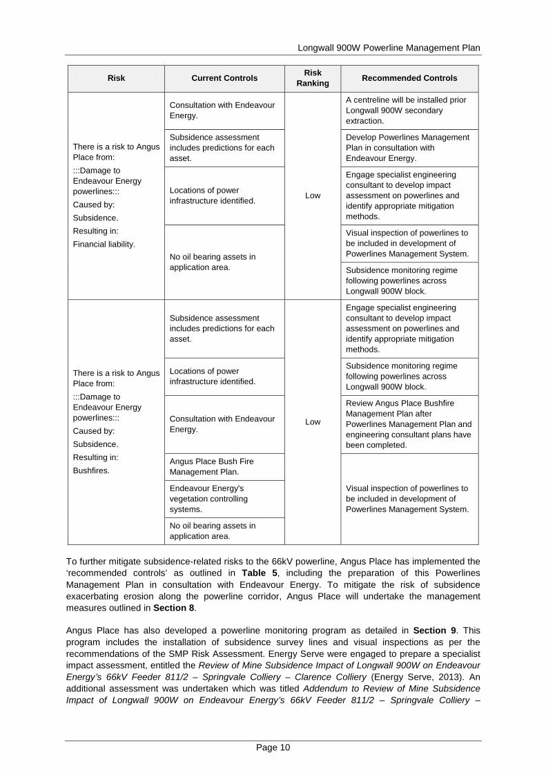
Longwall 900W Powerline Management Plan
Page 11
Clarence Colliery (Energy Serve 2013a) to assess the potential subsidence impacts associated with an increased mining height within Longwall 900W from 325 m to 3425 m A summary of the findings from these assessments has been outlined in Section 522 and copies of the reports have been provided as Appendices 1 and 2
Angus Place will undertake a review of the Bushfire Management Plan prior to the commencement of secondary extraction in Longwall 900W
Longwall 900W Powerline Management Plan
Page 12
7 PERFORMANCE MEASURES AND INDICATORS
71 Performance Measures
Subsidence impact performance measures are specified in Schedule 3 Condition 3A of PA 06_0021 (as modified) The performance measures specifically relating to the 66kV transmission line include
bull That the powerline is always safe and serviceable and bull Damage that does not affect safety or serviceability must be fully repairable and must be fully
repaired unless the owner agrees otherwise in writing
72 Performance Indicators
To establish compliance with the performance measures as outlined in Section 71 Angus Place has developed a monitoring program This monitoring program (see Section 9) will be used to demonstrate that the environmental performance satisfies the following performance indicators
bull Visual inspections of the 66kV powerline to identify that there are no obvious visual abnormalities and
bull Survey monitoring within the Project Area identifies that subsidence parameters (subsidence tilt strain and angle of draw) are within the limits of the prediction model
8 MANAGEMENT MEASURES
As per the recommendations of the Subsidence Prediction and Impact Assessment (DgS 2010) Review of Mine Subsidence Impact Of Longwall 900W on Endeavour Energyrsquos 66kV Feeder 8112 ndash Springvale Colliery ndash Clarence Colliery (Energy Serve 2013) and the SMP Risk Assessment the management and mitigation measures outlined in Sections 81 and 82 will be implemented by Angus Place during the secondary extraction of Longwall 900W
81 Endeavour Energy 66kV Powerline
As specified in Sections 521 and 523 the predicted subsidence and pole movements do not pose a problem with either ground clearance or structural integrity to any poles within the Project Area (Energy Serve 2013) Additionally the specialist assessment prepared by Energy Serve (2013) concluded that ldquono precautionary action is required and remedial action should not be necessaryrdquo Although no precautionary or remedial actions are expected to be required Energy Serve (2013) recommend that the movement of power poles and the consequent action of the spans should be observed throughout the proposed secondary extraction and subsidence Accordingly Angus Place propose to implement a detailed monitoring program for the Endeavour Energy 66kV powerline This program will be undertaken to confirm that the observed subsidence parameters are consistent with the predictions of DgS (2010) and Energy Serve (2013) This will be achieved by implementing the following measures
bull Implementing a subsidence monitoring program for the 66kV powerline as detailed in Section 92 that will include
o Surveying of the proposed centreline (the lsquoI Linersquo) that will be installed at the commencing end of Longwall 900W
o Surveying of fixed survey points (reflectors) near the top and base of each power pole associated with the Project Area (poles 201 ndash 211)
bull Implementing a visual inspection program that will include the use of photo monitoring (see Section 92) In the event that any obvious abnormalities are identified during an inspection a survey will be triggered
Longwall 900W Powerline Management Plan
Page 13
bull Angus Place will prepare and distribute the results of each survey to relevant stakeholders (see Section 14)
bull In the unlikely event that subsidence monitoring andor visual inspections identify that a performance indicator has been exceeded Angus Place will implement the contingency measures as detailed in the Trigger Action Response Plan (see Table 6) and
bull Following completion of subsidence in the vicinity of the 66kV powerline the final sags in the spans will be assessed to determine if they need to be corrected
82 Existing Erosion and Sedimentation Along Powerline Corridor
As outlined in Section 6 Angus Place completed an SMP Risk Assessment at the commencement of the Angus Place Longwalls 900W and 910 Integrated SMPExtraction Plan to identify potential subsidence related hazards that may result from the secondary extraction of longwall panels within the Project Area A risk that was identified during the risk assessment and relevant to the preparation of this Powerline Management Plan is the ldquopotential for subsidence to exacerbate existing erosion along the powerline easementrdquo Although the predicted maximum consequence for subsidence related erosion along the powerline corridor was ranked as being insignificant this risk was assessed as being lsquomoderatersquo as a result of the expected likelihood of this erosion occurring (ranked as probable)
A number of lsquorecommended controlsrsquo were identified during the SMP Risk Assessment that could be used to mitigate potential subsidence related risks As outlined in Table 5 a recommendation was made to mitigate the exacerbation of existing erosion along the powerline corridor by Angus Place which outlined a commitment to ldquoinvestigate monitoring and remedial requirements with Endeavour Energyrdquo Prior to the commencement of secondary extraction within Longwall 900W and at the convenience of Endeavour Energy Angus Place propose to undertake a joint inspection of the 66kV powerline corridor to assess the condition of the existing erosion Duringfollowing this inspection both companies can commence discussions with regard to an agreeable management approach
9 MONITORING PROGRAM
91 Baseline Monitoring
Baseline monitoring of the land within the Project Area will be undertaken prior to the commencement of secondary extraction within Longwall 900W Baseline data will be obtained by Angus Place using a combination of the following methods
bull Installation of a subsidence monitoring line (the ldquoIrdquo Line) that will be used to monitor the angle of draw subsidence tilt and strain The line will be surveyed prior to secondary extraction in Longwall 900W to establish pre-mining data
bull Installation of fixed survey points (reflectors) near the top and base of each power pole These points will be used to monitor subsidence relative pole movement change in sagtensions and variation of anchorage conditions These points will be surveyed twice prior to secondary extraction within Longwall 900W to establish reliable pre-mining data and
bull A visual inspection program will be undertaken by Angus Place that includes the use of photo monitoring points prior to the commencement of secondary extraction in Longwall 900W to establish the pre-mining condition of the Endeavour Energy 66kV powerline
92 Monitoring Subsidence Impacts
The Endeavour Energy 66kV powerline will be monitored pre and post mining for evidence of any subsidence related impacts Table 6 provides a summary of the subsidence monitoring program that will be undertaken to manage this feature Figure 3 illustrates the location of proposed subsidence monitoring that is relevant to the 66kV powerline Additional detail pertaining to subsidence monitoring
Longwall 900W Powerline Management Plan
Page 14
methodology relevant to the Project Area can be found in the Longwalls 900W and 910 Subsidence Monitoring and Reporting Program
Table 6 Subsidence Monitoring Program
Monitoring Method Parameter Frequency
Subsidence survey line Subsidence tilt strain and angle of draw
Prior and post secondary extraction within Longwall 900W
Fixed survey points
Subsidence relative pole movement1 change in sagtensions2 and variation of anchorage conditions3
Powerline monitoring will be undertaken at the following frequency
bull Twice prior to commencement of secondary extraction in Longwall 900W
bull When secondary extraction of Longwall 900W reaches the following chainages CH2000 CH1890 CH1820 CH1730 CH1530 (see Figure 3)
bull Three months after CH1530 survey at the completion of secondary extraction within Longwall 900W and
bull Six monthly until no significant4 difference between successive surveys is detected
Visual inspections (including photo monitoring)
Presence or absence of visual abnormalities
Photo monitoring and visual inspections of the powerline will be undertaken at the following frequency
bull Prior to the commencement of secondary extraction in Longwall 900W
bull Weekly from commencement of secondary extraction until Longwall 900W reaches chainage CH1450 (when all poles within the Project Area have been undermined)
bull Monthly for three months bull Bi-monthly for two inspections and bull Tri-monthly for three inspections
1 The relative movement ie lean will be determined through a comparison of the bearing and distance (horizontal projection) between the top and bottom reflector from one survey to the next Total lean will be referenced against the baseline survey bearing and distance 2 A comparison between the 3D coordinates of the reflector at the top of one pole to the next will determine a baseline distance between each pole at the level of the wire attachment point A change in distance between the tops of the poles will indicate a change in sag and tension of the wires between the two relevant power poles 3 Variations to anchorage conditions will be measured at a specific point placed on each anchor point 3D coordinates will be determined for the mark and its movement relative to the reflector at the top of the pole calculated and compared to the baseline survey The change in slope distance between the anchor point and the top of the pole should indicate any change in anchor tension 4 Significant is defined as being 15 times the difference in results from the two baseline surveys
Longwall 900W Powerline Management Plan
Page 15
93 Monitoring Environmental Consequences
Angus Place will implement the monitoring program as specified in Table 6 to monitor the development of predicted subsidence associated with the Endeavour Energy 66kV powerline (see Section 52) A contingency plan has been developed as a component of this Powerline Management Plan to outline management measures that will be implemented in the event that predicted environmental consequences are exceeded (see Section 12)
94 Success of Remediation Measures
In the event that remediation of the 66kV powerline is required Angus Place will undertake rehabilitation in consultation with relevant NSW Government Agencies Endeavour Energy and the Forestry Corporation of NSW (FCNSW) During consultation and prior to implementation of any remedial measures Angus Place will determine the ongoing monitoring requirements
9
10
11
12
13
14
15
16
17
19
31
34
35
36
37
38
18
21
20
32
33
Proposed Powerline Monitoring
Proposed Powerline Monitoring
LONG
WAL
L 900
WES
T
LONGWALL 970
LONGWALL 980
Prop
osed
I L
ine
Base Plan Data Source Centennial Angus Place Pty Ltd
FIGURE 3
Longwall 900W Powerline Management Plan
Powerline Monitoring
To be printed A4
VAngus PlaceCCC07-007FiguresFinalCADLongwall 900W Powerline Management PlanFg3_CCC07-007_Powerlines Monitoring Line_130809dwg
0 400m200
Scale 1 10 000
LEGEND
S
W
N
E
Colliery Holding Boundary
Angus Place Workings
Springvale Workings
Proposed Powerline Monitoring
Proposed Subsidence Line
Longwall 900W Powerline Management Plan
Page 17
10 CONSULTATION
In accordance with Schedule 3 Condition 3C(g) of PA 06_0021 (as modified) this Powerline Management Plan was provided to Endeavour Energy as part of the consultation process on 28 August 2013 No comments have been received from Endeavour Energy regarding this Powerline Management Plan
In November 2013 this Powerline Management Plan was updated to include the relevant findings as presented in the Addendum to Review of Mine Subsidence Impact of Longwall 900W on Endeavour Energyrsquos 66kV Feeder 8112 ndash Springvale Colliery ndash Clarence Colliery (Energy Serve 2013a) and the Subsidence Assessment Review for the Longwalls 900W and 910 Integrated SMPExtraction Plan Centennial Angus Place Colliery (DgS 2013) (see Sections 522 and 523) This plan was subsequently re-submitted to Endeavour Energy for consultation on 15 November 2013
Evidence of the consultation undertaken during the preparation of this Powerline Management Plan has been provided as Appendix 3
11 ADAPTIVE MANAGEMENT
Angus Place has developed an adaptive management approach that is designed to avoid repetition of any unpredicted subsidence impacts andor environmental consequences This approach will include the monitoring and periodic evaluation of environmental consequences against the performance indicators defined in Section 72 the implementation of the contingency plan (see Section 12) in the event that a performance indicator is exceeded and the review of this Powerline Management Plan as necessary (see Section 15)
12 CONTINGENCY PLAN
A TARP has been developed using the performance indicators for the 66kV powerline as outlined in Section 72 In the event that subsidence monitoring andor visual inspections identify that a performance indicator has been exceeded Angus Place will implement the contingency measures as detailed in the TARP (see Table 7)
Longwall 900W Powerline Management Plan
Page 18
Table 7 Trigger Action Response Plan for Endeavour Energy 66kV Powerline Aspect
Category Key Element
Trigger Response
Condition Green Condition Amber Condition Red
Endeavour Energy 66kV Powerline
Subsidence
Trigger Survey monitoring along the lsquoI Linersquo identifies that measured subsidence parameters (subsidence tilt and strain) are less than the limits specified by the prediction model (DgS 2010)
Survey monitoring along the lsquoI Linersquo identifies that measured subsidence parameters (subsidence tilt and strain) are up to but do not exceed the limits of the prediction model (DgS 2010)
Survey monitoring along the lsquoI Linersquo identifies that measured subsidence parameters (subsidence tilt and strain) exceed the limits of the prediction model (DgS 2010)
Response No response required Continue monitoring program No response required Continue monitoring program
If subsidence associated with the powerline exceeds the limits of the prediction model notify the Director-General of DPampI DTIRIS Endeavour Energy and the FCNSW of exceedance of subsidence predictions Investigate exceedance of subsidence prediction model Identify and implement remedial actions in consultation with relevant stakeholders if necessary (eg undertake review of Powerline Management Plan)
Trigger
Survey monitoring of fixed survey points (reflectors) on relevant power poles identify that measured subsidence andor relative pole movements are less than the limits specified by the prediction models (DgS 2010 Energy Serve 2013)
Survey monitoring of fixed survey points (reflectors) on relevant power poles identify that measured subsidence andor relative pole movements are up to but do not exceed the limits of the prediction models (DgS 2010 Energy Serve 2013)
Survey monitoring of fixed survey points (reflectors) on relevant power poles identify that measured subsidence andor relative pole movements exceed the limits of the prediction models (DgS 2010 Energy Serve 2013)
Response No response required Continue monitoring program No response required Continue monitoring program
If subsidence associated with the powerline exceeds the limits of the prediction model notify the Director-General of DPampI DTIRIS Endeavour Energy and the FCNSW of exceedance of subsidence predictions Investigate exceedance of subsidence prediction model Identify and implement remedial actions in consultation with relevant stakeholders if necessary (eg undertake review of Powerline Management Plan)
Evidence of damage
Trigger Visual inspections of the site identify that there is no evidence of abnormalities to the powerline
Visual inspections identify potential evidence of abnormalities to the powerline ie changes to powerline ground clearance or pole verticality
Visual inspections identify evidence of abnormalities to the powerline ie obvious changes to powerline ground clearance or pole verticality
Response No response required Continue monitoring program
Review previous photographic evidence to identify if there have been visual changes to the powerline since the commencement of secondary extraction in Longwall 900W ie pole verticality If the review of photographic evidence identifies that there are no abnormalities continue monitoring program If abnormalities are identified undertake survey monitoring to identify if measured subsidence andor relative pole movements are within the limits of the prediction models (DgS 2010 Energy Serve 2013) If measured subsidence andor relative pole movements are within the limits of the prediction models report the results to the stakeholders specified in Table 9 Continue monitoring program If measured subsidence andor relative pole movements are beyond the limits of the prediction models undertake management as outlined for Condition Red responses
Undertake survey monitoring to identify if measured subsidence andor relative pole movements are within the limits of the prediction models (DgS 2010 Energy Serve 2013) If measured subsidence andor relative pole movements are within the limits of the prediction models report the results to the stakeholders specified in Table 9 Continue monitoring program If measured subsidence andor relative pole movements are beyond the limits of the prediction models notify the Director-General of DPampI DTIRIS Endeavour Energy and the FCNSW of exceedance of subsidence predictions Erect warning signs and danger tape in immediate area Investigate exceedance of subsidence prediction model Identify and implement remedial actions in consultation with relevant stakeholders if necessary
Longwall 900W Powerline Management Plan
Page 19
13 ROLES AND RESPONSIBILITIES
The responsibility for implementation monitoring and review of the Powerline Management Plan lies with the Environment and Community Coordinator The ultimate responsibility for the implementation of the Powerline Management Plan lies with the Mine Manager who shall make appropriate resources available The roles and responsibilities for this Powerline Management Plan are outlined in Table 8
Table 8 Key Personnel and Accountabilities Position Responsibility
Mine Manager bull Ensuring that sufficient resources are available to implement and execute the
requirements of this Plan and bull Reporting triggersnon-conformances to external stakeholders
Environment and Community Coordinator
Implementation monitoring and review of this plan including bull The carrying out of inspections
bull The installation and maintenance of signage
bull Reporting triggersnon-conformances internally to the Mine Manager as appropriate
bull Consulting with Endeavour Energy regarding any serviceability issues arising from subsidence
bull Consultation during the review process with relevant stakeholders and distributing this Powerline Management Plan
bull Coordinating any remediation work as required in consultation with Endeavour Energy and the FCNSW
bull Co-ordinating the generation and submission of formal reporting requirements outlined in this Plan (eg End of Panel Reports and the Annual Environmental Management Report) and
bull Reviewing this Powerline Management Plan
Endeavour Energy
bull Undertake inspections as required with Environment and Community Coordinator and
bull Determine appropriate remedial measures in conjunction with Environment and Community Coordinator if required
14 REPORTING
In accordance with the requirements of the Draft Guidelines for the Preparation of Extraction Plans (DPampI 2012) Angus Place will submit the following reports to the DPampI and DTIRIS during the secondary extraction of Longwalls 900W and 910
bull Bi-monthly Subsidence Impact Reports - These reports will be submitted following the regular monthly inspections if any new subsidence impacts are identified and
bull Six-monthly Environmental Monitoring Report - This report will include
minus a comprehensive summary of all impacts including a revised characterisation according to the relevant TARP and any proposed actions resulting from the relevant TARP (see Section 12)
minus an assessment of compliance with relevant performance indicators (see Section 72) and
Longwall 900W Powerline Management Plan
Page 20
minus a comprehensive summary of all quantitative and qualitative environmental monitoring results
The Annual Environmental Management Report (AEMR)Annual Review will be made available on the Centennial Coal website and will include subsidence monitoring results performance against subsidence predictions and identification of any subsidence related environmental impacts identified during the reporting period
In accordance with the requirements of Schedule 5 Condition 6 of PA 06_0021 (as modified) Angus Place will notify the Director-General of DPampI Endeavour Energy and any other relevant agencies of any powerline management related incident resulting from the extraction of Longwalls 900W and 910 as soon as practicable after becoming aware of the incident Within seven days of the incident the Proponent shall provide the Director-General of DPampI and any relevant agencies with a detailed report on the incident
Angus Place will also prepare an End of Panel Report to encompass all environmental and subsidence monitoring including a comparison of actual impacts with predicted subsidence impacts This report will be submitted to DTIRIS within three months of secondary extraction being completed in each longwall panel
Following the completion of each survey as outlined in Table 6 survey results will be compiled into a report that will be distributed to representatives of Endeavour Energy Energy Serve and Angus Place Contact details for the relevant representatives have been provided in Table 9
Table 9 Primary Contacts
Company Contact Title Contact Details
Endeavour Energy Rod Joyce Operational Planning
T 02 9853 6823
E RodJoyceendeavourenergycomau
Energy Serve Kevin Rugg Principal Consultant T 02 6885 3224
E kevinenergyservecomau
Angus Place
Alan Mellor Mine Surveyor T 02 6354 8702
E AlanMellorcentennialcoalcomau
Natalie Conroy Environment and Community Coordinator
T 02 6354 8938
E NatalieConroycentennialcoalcomau
15 REVIEW
This Powerline Management Plan will be reviewed in the event that the following occur
bull Endeavour Energy raise issues that necessitate a review bull There are changes to the management requirements (eg changes to related approvals) bull Where unpredicted impacts or consequences have required implementation of contingency
actions under this plan or bull Monitoring incident or audit processes demonstrate that a review is warranted
Any amendments to the Powerline Management Plan will be undertaken in consultation with Endeavour Energy and relevant stakeholders Following any changes a copy of the amended Powerline Management Plan will be forwarded to the Executive Director Mineral Resources of DTIRIS and the Director-General of the DPampI for approval
Longwall 900W Powerline Management Plan
Page 21
16 REFERENCES
Centennial Coal (2008) Centennial Coal Risk Management Standard (Management Standard ndash 004)
DgS (2010) Subsidence Prediction and Impact Assessment Report no ANP_0021
DgS (2013) Subsidence Assessment Review for the Longwalls 900W and 910 Integrated SMPExtraction Plan Centennial Angus Place Colliery Report No ANP-0027
Department of Mineral Resources (2003) Guideline for Applications for Subsidence Management Approvals
DPampI (2012) Draft Guidelines for the Preparation of Extraction Plans
EnergyServe (2013) Review of Mine Subsidence Impact of Longwall 900W on Endeavour Energyrsquos 66kV Feeder 8112 ndash Springvale Colliery ndash Clarence Colliery
Energy Serve (2013a) Addendum to Review of Mine Subsidence Impact of Longwall 900W on Endeavour Energyrsquos 66kV Feeder 8112 ndash Springvale Colliery ndash Clarence Colliery
RPS (2010) Angus Place Colliery NSW Modification of Project Approval 06_0021 under Section 75W Part 3A
Longwall 900W Powerline Management Plan
This page has been intentionally left blank
Appendix 1 Review of M
ine Subsidence Impact of
Longwall 900W
on Endeavour Energyrsquos 66kV Feeder
Jemtom Pty Ltd ta Energy Serve bull ABN 36 078 771 650 Suite 1 Level 1 139 Macquarie Street Dubbo NSW 2830
Tel (02) 6885 3224 bull Fax (02) 6885 3210 bull Mobile 0427 853 224
CENTENNIAL COAL
Angus Place Colliery Wolgan Road Lidsdale
Review of Mine Subsidence Impact
Of Longwall 900W on Endeavour Energyrsquos
66kV Feeder 8112 ndash Springvale Colliery-Clarence Colliery
2 May 2013
Amendment A
Power System Engineering amp
Energy Advisory Services
Page 2 May 2 2013
Disclaimer Due to the unpredictable nature of mine subsidence Energy Serve is unable to accurately determine the behaviour of powerlines under the influence of such movements This report and the recommendations contained herein are based on the information provided and are intended to be sufficiently conservative to cater for the range of expected movements
It is not practical to predict the dynamic nature of the subsidence or all the possible intermediate outcomes hence it is recommended that regular inspection and monitoring is undertaken during and following longwall mining in the vicinity of the powerlines in question
Energy Serve will not be liable or responsible for any damage loss of revenue loss of production or unsafe conditions caused by mine subsidence on powerlines
Contents
Amendments 2 Background 3 Methodology 3 Predicted Subsidence at Pole Locations 4 Results 4
Existing Ground Clearance Issue outside Subsidence Area 4 Ground Clearance 5 Pole amp Conductor Loading 5
Summary 7 Recommendations 7 Endeavour Energy Consultation amp Approval 7 Appendix A ndash 66kV Feeder relative to Longwall 900 West (LW900W) 8 Appendix B ndash Plan amp Profile ndash Pre-subsidence 9 Appendix C ndash Plan amp Profile ndash Post-subsidence 12 Appendix D ndash Section Usage Report ndash Existing 15 Appendix E ndash Section Usage Report ndash Post-subsidence 17 Appendix F ndash Structure Usage Report ndash Existing 19 Appendix G ndash Structure Usage Report ndash Post-subsidence 24 Appendix H ndash Endeavour Energy ndash David Mate ndash Email 25 March 2013 29
Amendments
Draft Draft for client review 01112012
Final Draft Final Draft for client review 25012013
Amendment A Endeavour Energy consultation included 01052013
Page 3 May 2 2013
Background
Energy Serve has been commissioned by GSS Environmental on behalf of Centennial Coal ndash Angus Place Colliery to review the impact of the proposed mining of the Longwall 900 West (900W) on Endeavour Energyrsquos 66kV 8112 Feeder
This feeder is generally 66kV delta suspension construction however there are four in-line or angle strain structures within the six spans potentially impacted by the predicted subsidence
The suspension structures have a significant capacity to absorb the pole movements A potential subsidence related issue can be the strain structures subject to longitudinal movement as this can have a significant effect on conductor tensions and thereby ground clearances
Appendix A shows the 8112 Feeder in relation to the proposed Longwall 900W and other workings associated with the Centennial Coal - Angus Place Colliery
The data used to conduct this review included
bull Centreline survey of the existing natural surface conducted by Cramer Elliston amp Hayes (Lithgow) Surveyors
bull Record of structure details and photos collected by Cramer Elliston amp Hayes and bull Subsidence report by Ditton Geotechnical Services Pty Ltd (DgS) for Longwalls 910 amp 900
West including predicted subsidence contours plus surface translation and rotations at each structure
Methodology
The centreline survey data was imported into PLSCADD to create an existing surface profile PLSCADD was then also used to modify the centreline data within the 900W subsidence contours to create a post-subsidence centreline The two sets of data were used to create pre- and post-subsidence profiles under the powerline
The impact of longwall mining includes not just vertical subsidence at the surface Structures at or near the surface also experience translational and rotational movements which may be transient in nature as the longwall mining progresses past the point of concern However some residual translation and rotation will remain depending on the relative position of the pole in relation to the direction and sides of the longwall cut
Pole structures are particularly sensitive to rotational impacts due to the relative height of the pole above ground What seems like a minimal rotation at ground level will get multiplied into significant movements at the pole top These movements are critical to pole top and conductor loadings as well as inter-circuit clearances A small pole top movement can result in substantial conductor tension and load changes
PLSCADD has been used to model the following
bull Before amp after ground clearance for statutory clearance and where practical intermediate scenarios where the subsidence transitions through the site and
bull Structure and conductor loading due to the abovementioned translation and rotation effects
The PLSCADD powerline software has the capability of modelling the impact on installed systems The effect of pole movement andor splicing in or cutting out of conductor can be modelled with a high degree of confidence
Page 4 May 2 2013
Predicted Subsidence at Pole Locations
The following table of predicted subsidence translation and rotations were supplied by DgS See Table 12 p37 of DgS Report No ANP-0021
Pole ID
Final Subsidence due to 900W
(mm)
Final Tilt Towards
Longwall due to 900W (mmm)
Final Tilt Along Axis of Longwall due
to 900W (mmm)
Predicted Horizontal Movement Towards
Longwall due to 900W (mm)
Predicted Horizontal
Movement Along Main Axis of
Longwall due to 900W (mm)
201 0 0 0 0 0 202 0 0 0 0 0 203 0 0 0 0 0 204 30 03 03 5 5 205 720 83 65 133 103 206 1000 55 -20 -88 -31 207 380 74 -57 -118 -91 208 40 04 -02 -6 -4 209 0 0 0 0 0 210 0 0 0 0 0 211 0 0 0 0 0
Results
The maximum predicted surface subsidence to be experienced by the 66kV feeder is 1000mm at Pole 206 Subsidence is predicted to extend over a total route length of 970 metres but will exceed 200 mm over a distance of 360 metres only impacting Poles 205-206-207
Appendix B contains Plan amp Profile Sheets showing the existing mains at a maximum operating temperature of 85degC and the pre-subsidence ground profile
Existing Ground Clearance Issue outside Subsidence Area
It is apparent that there is more than enough ground clearance throughout the subsidence area to allow for the predicted vertical subsidence
However in the span between Poles 209 amp 210 it is evident that there is insufficient clearance in the vicinity of Pole 210
Appendix A shows that Pole 210 is not within the predicted subsidence area for Longwall 900W and has not been impacted by subsidence due to other mine workings It is located outside any past or future subsidence area
Endeavour Energy may wish to review the attached profile (Appendix B) and consider taking remedial action The existing lines do not meet statutory clearance at 65degC
Page 5 May 2 2013
Ground Clearance
It can be seen that the maximum projected subsidence occurs in the vicinity of poles 205 206 amp 207 with up to 1000mm vertical displacement predicted at Pole 206 and 720mm at Pole 205
The excess ground clearance in these spans is more than sufficient to cater for the progressive subsidence impacting each pole It is likely in any case that pole 206 and the surface between 205 amp 206 will commence subsiding before pole 205 reaches its final level
The predicted subsidence at poles 204 amp 208 are less than 50mm and will therefore not be significantly impacted
A potential subsidence related issue associated with the 66kV powerline may be conductor tension changes due to pole head movement particularly at pole 205 due to its being located on the side of the subsidence area and predicted to experience the highest horizontal displacement and tilt
Appendix C indicates that the tension changes for the predicted pole top displacements at pole 205 are minimal and that no remedial action appears to be necessary to maintain statutory ground clearance
Figures 1 2 amp 3 show the pole tops for structures 205 206 amp 207 respectively
Likewise the tension changes due to the predicted pole top displacements on poles 206 amp 207 are also minimal and no precautionary or remedial action is necessary for preservation of ground clearance within the 900W subsidence footprint
Figure 1 - Structure 205 pole top
Pole amp Conductor Loading
Another potential issue with these spans is the impact of pole top movement of poles 205 206 amp 207 on the loading of structures and conductor tensions
Page 6 May 2 2013
Appendices D amp E include Pre amp Post-subsidence Section Usage reports The tensions increase slightly (2-3) but remain well within the allowable 70 of conductor breaking load
Appendices F amp G include Pre amp Post-subsidence Structure Usage reports Structure usages also increase slightly (1-3) but remain well within structure capacities Maximum usage is lt 75
Figure 2 - Structure 206 pole top
Figure 3 - Structure 207 pole top
Page 7 May 2 2013
Summary
The check survey has indicated an existing ground clearance issue between poles 209 amp 210 This span is outside the current and any previous subsidence areas Endeavour Energy may wish to follow this up
The predicted pole movements and subsidence do not pose a problem with either ground clearance or structural integrity of any of the poles from 204 to 208 contained within the subsidence footprint No precautionary action is required and remedial action should not be necessary
Recommendations
It is not recommended that any precautionary actions be taken
The movement of these poles and the consequent action of the spans should be observed throughout the proposed mining and subsidence in order to validate the predictions and ensure clearances have been maintained at all times and structure loadings have not been exceeded
Following completion of the subsidence in this vicinity the final sags in the spans should be assessed as to whether they need to be corrected
In any case the powerline should be closely monitored throughout the mining subsidence process to ensure no unexpected hazards arise and statutory clearances are maintained
Endeavour Energy Consultation amp Approval
Following review and endorsement by Centennial Coal this report was submitted to Endeavour Energy (EE) for consideration It was initially uncertain as to who within EE would provide the final approval on behalf of EE
The identification of the existing clearance issue caused an immediate reaction and action is underway to address this problem
Once the appropriate officer was identified the report was assessed by David Mate and approved by email A copy of the email approval and precedent trail of emails is included in Appendix H
No remedial action is required
Monitoring of the powerline is recommended throughout the mining subsidence process as detailed above
Kevin Rugg
Principal Consultant
Jemtom Pty Ltd ta Energy Serve bull ABN 36 078 771 650 Suite 1 Level 1 139 Macquarie Street Dubbo NSW 2830
Tel (02) 6885 3224 bull Fax (02) 6885 3210 bull Mobile 0427 853 224
Appendix A ndash 66kV Feeder relative to Longwall 900 West (LW900W)
Jemtom Pty Ltd ta Energy Serve bull ABN 36 078 771 650 Suite 1 Level 1 139 Macquarie Street Dubbo NSW 2830
Tel (02) 6885 3224 bull Fax (02) 6885 3210 bull Mobile 0427 853 224
Appendix B ndash Plan amp Profile ndash Pre-subsidence
PLS
-CA
DD
Dra
win
g
-100
0
100
200
300
400
500
600
700
800
900
1000
1100
1115
1120
1125
1130
1135
1140
1145
1150
1155
1160
1165
1170
1175
1180
1185
1190
1195
1200
1205
1210
1215
1115
1120
1125
1130
1135
1140
1145
1150
1155
1160
1165
1170
1175
1180
1185
1190
1195
1200
1205
1210
1215
PI 0deg0000
PI 41deg0000
PI -14deg4800
PI -16deg5400
19912 1045 Sunny 13C 02 ms
211 211_17-201pol
210 210_17-202pol
209 209_215-203pol
208 208_185-204pol
207 207_17-205pol
206 206_185-206pol
1341
3829
2207
2417
1227 9700
m
Ext
ent of su
bsi
dence
zone
66kV
PB-206
PB-207
PB-208
PB-209
PB-21
PB-211
14
15
16
17
211
210
209
208
207
206
PI 000
0deg0000
PI 13415 41deg0000
517034deg4800
110218
16deg5400
AN
GU
S P
L 6
6 2
0121101
Exi
stin
g11
12
012
Page 1
2V
ert
S
cale
Horiz
Sca
le
100
m
500
m
North
PLS
-CA
DD
Dra
win
g
1100
1200
1300
1400
1500
1600
1700
1800
1900
2000
1125
1130
1135
1140
1145
1150
1155
1160
1165
1170
1175
1180
1185
1190
1195
1200
1205
1210
1215
1220
1225
1125
1130
1135
1140
1145
1150
1155
1160
1165
1170
1175
1180
1185
1190
1195
1200
1205
1210
1215
1220
1225
PI 0deg0000
206 206_185-206pol
205 205_185-207pol
204 204_17-208pol
203 203_185-209pol
202 202_17-2010pol
201 201_17-2011pol
1124
2293
1521
1266
2347
Ext
ent of su
bsi
dence
zone
PO
WE
RL
I NE
VPB-2
03
PB-2
04
PB-2
05
PB-2
0607
PPB-2
00
PB20
1
PB-2
0235
36
37
38
206
205
204
203
202
201
PI 110218-16deg5400
PI 1957190deg0000
AN
GU
S P
L 6
6 2
0121101
Exi
stin
g11
12
012
Page 2
2V
ert
S
cale
Horiz
Sca
le
100
m
500
m
Nor
th
Page 12 May 2 2013
Appendix C ndash Plan amp Profile ndash Post-subsidence
PLS
-CA
DD
Dra
win
g
-100
0
100
200
300
400
500
600
700
800
900
1000
1100
1115
1120
1125
1130
1135
1140
1145
1150
1155
1160
1165
1170
1175
1180
1185
1190
1195
1200
1205
1210
1215
1115
1120
1125
1130
1135
1140
1145
1150
1155
1160
1165
1170
1175
1180
1185
1190
1195
1200
1205
1210
1215
PI 0deg0000
PI 41deg0000
PI -14deg4800
PI -16deg5400
19912 1045 Sunny 13C 02 ms
211 211_17-201pol
210 210_17-202pol
209 209_215-203pol
208 208_185-204pol
207 207_17-205pol
206 206_185-206pol
1341
3829
2207
2417
1227 9700
m
Ext
ent of su
bsi
dence
zone
66kV
PB-206
PB-207
PB-208
PB-209
PB-21
PB-211
14
15
16
17
211
210
209
208
207
206
PI 000
0deg0000
PI 13415 41deg0000
517034deg4800
110218
16deg5400
AN
GU
S P
L 6
6 2
0121101
Post
subs
+ p
ole
mvt
s11
12
012
Page 1
2V
ert
S
cale
Horiz
Sca
le
100
m
500
m
North
PLS
-CA
DD
Dra
win
g
1100
1200
1300
1400
1500
1600
1700
1800
1900
2000
1125
1130
1135
1140
1145
1150
1155
1160
1165
1170
1175
1180
1185
1190
1195
1200
1205
1210
1215
1220
1225
1125
1130
1135
1140
1145
1150
1155
1160
1165
1170
1175
1180
1185
1190
1195
1200
1205
1210
1215
1220
1225
PI 0deg0000
206 206_185-206pol
205 205_185-20_subs7pol
204 204_17-208pol
203 203_185-209pol
202 202_17-2010pol
201 201_17-2011pol
1124
2293
1521
1266
2347
Ext
ent of su
bsi
dence
zone
PO
WE
RL
I NE
VPB-2
03
PB-2
04
PB-2
05
PB-2
0607
PPB-2
00
PB20
1
PB-2
0235
36
37
38
206
205
204
203
202
201
PI 110218-16deg5400
PI 1957190deg0000
AN
GU
S P
L 6
6 2
0121101
Post
subs
+ p
ole
mvt
s11
12
012
Page 2
2V
ert
S
cale
Horiz
Sca
le
100
m
500
m
Nor
th
Page 15 May 2 2013
Appendix D ndash Section Usage Report ndash Existing
Energy Serve
Page 11
PLS-CADD Version 1210x64 40015 PM Thursday 1 November 2012
Energy Serve
Project Name cuserskevin ruggdocumentsenergy servegss environmentalangus placeplsangus pl 66 20121101DON
Line Title Existing
Section Usage Report
Sec Cable From To Percent OK
No Name Str Str Usage NG
-----------------------------------
4 lemon 208 206 498 OK
5 lemon 206 204 489 OK
0 section violations OK
Check Section Summary
designates highest percent of allowable capacity
Sec Cable From To WC Weather Case Condition Allowable Actual Allowable Actual Allowable Actual of OK
No Name Str Str No Description of of Tension Tension Catenary Catenary Allowable or
No No Ultimate Ultimate (N) (N) (m) (m) Capacity NG
-------------------------------------------------------------------------------------------------------------------------------------
4 lemon 208 206 7 Limit 1000 Initial RS 700 348 313862 13423 498 OK
5 lemon 206 204 7 Limit 1000 Initial RS 700 343 308671 13242 489 OK
Page 17 May 2 2013
Appendix E ndash Section Usage Report ndash Post-subsidence
Energy Serve
Page 11
PLS-CADD Version 1210x64 35823 PM Thursday 1 November 2012
Energy Serve
Project Name cuserskevin ruggdocumentsenergy servegss environmentalangus placeplsangus pl 66 20121101DON
Line Title Post subs + pole mvts
Section Usage Report
Sec Cable From To Percent OK
No Name Str Str Usage NG
-----------------------------------
4 lemon 208 206 539 OK
5 lemon 206 204 519 OK
0 section violations OK
Check Section Summary
designates highest percent of allowable capacity
Sec Cable From To WC Weather Case Condition Allowable Actual Allowable Actual Allowable Actual of OK
No Name Str Str No Description of of Tension Tension Catenary Catenary Allowable or
No No Ultimate Ultimate (N) (N) (m) (m) Capacity NG
-------------------------------------------------------------------------------------------------------------------------------------
4 lemon 208 206 7 Limit 1000 Initial FE 700 378 340206 14565 539 OK
5 lemon 206 204 7 Limit 1000 Initial FE 700 363 327374 14052 519 OK
Page 19 May 2 2013
Appendix F ndash Structure Usage Report ndash Existing
Energy Serve
Page 14
PLS-CADD Version 1210x64 40113 PM Thursday 1 November 2012
Energy Serve
Project Name cuserskevin ruggdocumentsenergy servegss environmentalangus placeplsangus pl 66 20121101DON
Line Title Existing
Structure Locations and Usage Report
Structure Structure Station Line --Constraints--- Structure Insulator Minimum Pole OK
Number Name Angle Prohib Req Extra Strength Swing Required Tip or
Zone Pos Cost Usage Usage Vertical Deflection NG
Load Usage
(m) (deg) () () (Uplift) ()
---------------------------------------------------------------------------------------------------------
208 208_185-204pol 73777 000 0 737 00 OK OK
207 207_17-205pol 97945 000 0 531 320 OK OK
206 206_185-206pol 110218 -1690 Y 0 698 00 OK OK
205 205_185-207pol 121453 000 0 432 495 OK OK
204 204_17-208pol 144382 000 0 694 00 OK OK
0 structure violations 0 structure warnings OK
Energy Serve
Page 24
Multiple Structure Suspension Insulator Swing Angles and V-String Load Angles
Str Set Phase Swing Weather Wire Min Max Min Max of OK
Cond Case Condition Allowed Allowed Calc Calc Allowed
Description (deg) (deg) (deg) (deg) Swing
-----------------------------------------------------------------------------------------------------
207 3 1 1 Hot 85 Creep RS -900 900 -40 -40 45 OK
2 1 Hot 85 Creep RS -900 900 27 27 30 OK
3 1 Hot 85 Creep RS -900 900 -26 -26 29 OK
1 2 Swing 210 Initial RS -900 900 -166 57 184 OK
2 2 Swing 210 Initial RS -900 900 -78 153 170 OK
3 2 Swing 210 Initial RS -900 900 -142 72 158 OK
1 3 Swing 500 Initial RS -900 900 -288 188 320 OK
2 3 Swing 500 Initial RS -900 900 -212 280 311 OK
3 3 Swing 500 Initial RS -900 900 -261 197 290 OK
1 4 Cold 0 Initial RS -900 900 -59 -59 65 OK
2 4 Cold 0 Initial RS -900 900 40 40 45 OK
3 4 Cold 0 Initial RS -900 900 -37 -37 42 OK
205 1 1 Hot 85 Creep RS -900 900 -64 -64 71 OK
2 1 Hot 85 Creep RS -900 900 45 45 50 OK
3 1 Hot 85 Creep RS -900 900 -41 -41 46 OK
1 2 Swing 210 Initial RS -900 900 -276 81 307 OK
2 2 Swing 210 Initial RS -900 900 -123 263 293 OK
3 2 Swing 210 Initial RS -900 900 -231 107 257 OK
1 3 Swing 500 Initial RS -900 900 -444 295 493 OK
2 3 Swing 500 Initial RS -900 900 -343 446 495 OK
3 3 Swing 500 Initial RS -900 900 -400 301 444 OK
1 4 Cold 0 Initial RS -900 900 -115 -115 128 OK
2 4 Cold 0 Initial RS -900 900 85 85 94 OK
3 4 Cold 0 Initial RS -900 900 -72 -72 80 OK
Energy Serve
Page 34
Multiple Structure Minimum Vertical Load (Uplift) Summary
Str Set Phase Swing Weather Wire Min Vert Vert Vert OK
Cond Case Condition Req Load Load Load
Description Vert Wind Wind Margin
Load From From
Left Right
(N) (N) (N) (N)
-----------------------------------------------------------------------------------
207 3 1 1 Hot 85 Creep RS 0 2967 2967 2967 OK
2 1 Hot 85 Creep RS 0 2901 2901 2901 OK
3 1 Hot 85 Creep RS 0 3069 3069 3069 OK
1 2 Swing 210 Initial RS 0 3982 3982 3982 OK
2 2 Swing 210 Initial RS 0 3858 3858 3858 OK
3 2 Swing 210 Initial RS 0 4172 4172 4172 OK
1 3 Swing 500 Initial RS 0 4246 4246 4246 OK
2 3 Swing 500 Initial RS 0 4107 4107 4107 OK
3 3 Swing 500 Initial RS 0 4459 4459 4459 OK
1 4 Cold 0 Initial RS 0 4175 4175 4175 OK
2 4 Cold 0 Initial RS 0 4041 4041 4041 OK
3 4 Cold 0 Initial RS 0 4382 4382 4382 OK
205 1 1 Hot 85 Creep RS 0 1936 1936 1936 OK
2 1 Hot 85 Creep RS 0 1853 1853 1853 OK
3 1 Hot 85 Creep RS 0 2033 2033 2033 OK
1 2 Swing 210 Initial RS 0 2173 2173 2173 OK
2 2 Swing 210 Initial RS 0 2016 2016 2016 OK
3 2 Swing 210 Initial RS 0 2359 2359 2359 OK
1 3 Swing 500 Initial RS 0 2231 2231 2231 OK
2 3 Swing 500 Initial RS 0 2056 2056 2056 OK
3 3 Swing 500 Initial RS 0 2438 2438 2438 OK
1 4 Cold 0 Initial RS 0 2220 2220 2220 OK
2 4 Cold 0 Initial RS 0 2049 2049 2049 OK
3 4 Cold 0 Initial RS 0 2424 2424 2424 OK
Energy Serve
Page 44
Page 24 May 2 2013
Appendix G ndash Structure Usage Report ndash Post-subsidence
Energy Serve
Page 14
PLS-CADD Version 1210x64 40449 PM Thursday 1 November 2012
Energy Serve
Project Name cuserskevin ruggdocumentsenergy servegss environmentalangus placeplsangus pl 66 20121101DON
Line Title Post subs + pole mvts
Structure Locations and Usage Report
Structure Structure Station Line --Constraints--- Structure Insulator Minimum Pole OK
Number Name Angle Prohib Req Extra Strength Swing Required Tip or
Zone Pos Cost Usage Usage Vertical Deflection NG
Load Usage
(m) (deg) () () (Uplift) ()
--------------------------------------------------------------------------------------------------------------
208 208_185-204pol 73777 000 0 747 00 OK OK
207 207_17-20_subs5pol 97945 000 0 606 288 OK OK
206 206_185-20_subs6pol 110218 -1690 Y 0 728 00 OK OK
205 205_185-20_subs7pol 121453 000 0 447 449 OK OK
204 204_17-208pol 144382 000 0 714 00 OK OK
0 structure violations 0 structure warnings OK
Energy Serve
Page 24
Multiple Structure Suspension Insulator Swing Angles and V-String Load Angles
Str Set Phase Swing Weather Wire Min Max Min Max of OK
Cond Case Condition Allowed Allowed Calc Calc Allowed
Description (deg) (deg) (deg) (deg) Swing
-----------------------------------------------------------------------------------------------------
207 3 1 1 Hot 85 Creep FE -900 900 -37 -37 41 OK
2 1 Hot 85 Creep FE -900 900 29 29 32 OK
3 1 Hot 85 Creep FE -900 900 -23 -23 26 OK
1 2 Swing 210 Initial FE -900 900 -149 49 165 OK
2 2 Swing 210 Initial FE -900 900 -62 141 157 OK
3 2 Swing 210 Initial FE -900 900 -126 64 140 OK
1 3 Swing 500 Initial FE -900 900 -259 165 288 OK
2 3 Swing 500 Initial FE -900 900 -181 255 284 OK
3 3 Swing 500 Initial FE -900 900 -234 174 260 OK
1 4 Cold 0 Initial FE -900 900 -53 -53 59 OK
2 4 Cold 0 Initial FE -900 900 42 42 47 OK
3 4 Cold 0 Initial FE -900 900 -33 -33 37 OK
205 1 1 Hot 85 Creep FE -900 900 -65 -65 72 OK
2 1 Hot 85 Creep FE -900 900 34 34 38 OK
3 1 Hot 85 Creep FE -900 900 -42 -42 47 OK
1 2 Swing 210 Initial FE -900 900 -253 52 281 OK
2 2 Swing 210 Initial FE -900 900 -113 224 249 OK
3 2 Swing 210 Initial FE -900 900 -212 84 236 OK
1 3 Swing 500 Initial FE -900 900 -404 237 449 OK
2 3 Swing 500 Initial FE -900 900 -304 393 437 OK
3 3 Swing 500 Initial FE -900 900 -365 257 406 OK
1 4 Cold 0 Initial FE -900 900 -115 -115 127 OK
2 4 Cold 0 Initial FE -900 900 65 65 72 OK
3 4 Cold 0 Initial FE -900 900 -73 -73 81 OK
Energy Serve
Page 34
Multiple Structure Minimum Vertical Load (Uplift) Summary
Str Set Phase Swing Weather Wire Min Vert Vert Vert OK
Cond Case Condition Req Load Load Load
Description Vert Wind Wind Margin
Load From From
Left Right
(N) (N) (N) (N)
-----------------------------------------------------------------------------------
207 3 1 1 Hot 85 Creep RS 0 3066 3066 3066 OK
2 1 Hot 85 Creep RS 0 3006 3006 3006 OK
3 1 Hot 85 Creep RS 0 3179 3179 3179 OK
1 2 Swing 210 Initial RS 0 4193 4186 4186 OK
2 2 Swing 210 Initial RS 0 4087 4086 4086 OK
3 2 Swing 210 Initial RS 0 4426 4419 4419 OK
1 3 Swing 500 Initial RS 0 4488 4474 4474 OK
2 3 Swing 500 Initial RS 0 4364 4361 4361 OK
3 3 Swing 500 Initial RS 0 4742 4726 4726 OK
1 4 Cold 0 Initial RS 0 4388 4388 4388 OK
2 4 Cold 0 Initial RS 0 4275 4275 4275 OK
3 4 Cold 0 Initial RS 0 4640 4640 4640 OK
205 1 1 Hot 85 Creep RS 0 1968 1968 1968 OK
2 1 Hot 85 Creep RS 0 1887 1887 1887 OK
3 1 Hot 85 Creep RS 0 2061 2061 2061 OK
1 2 Swing 210 Initial RS 0 2224 2245 2224 OK
2 2 Swing 210 Initial RS 0 2074 2059 2059 OK
3 2 Swing 210 Initial RS 0 2401 2412 2401 OK
1 3 Swing 500 Initial RS 0 2315 2353 2315 OK
2 3 Swing 500 Initial RS 0 2170 2142 2142 OK
3 3 Swing 500 Initial RS 0 2518 2539 2518 OK
1 4 Cold 0 Initial RS 0 2274 2274 2274 OK
2 4 Cold 0 Initial RS 0 2087 2087 2087 OK
3 4 Cold 0 Initial RS 0 2461 2461 2461 OK
Energy Serve
Page 44
Page 29 May 2 2013
Appendix H ndash Endeavour Energy ndash David Mate ndash Email 25 March 2013
From David MateTo Kevin RuggSubject RE Centennial Coal - Angus Place - Subsidence Impact of Endeavour Energy 66kV Feeder 811Date Monday 25 March 2013 120800 PMAttachments image001png
Hi Kevin Based on the information in the report I have no issues in relation to the subsidence at AngusPlace
RegardsDavid David MateOverhead amp Underground Mains Manager ( 02 9853 6010Egrave 0413 227 4997 02 9853 6021 davidmateendeavourenergycomau 51 Huntingwood Drive Huntingwood NSW 2148 wwwendeavourenergycomau
From Kevin Rugg [mailtokevinenergyservecomau] Sent Monday 25 March 2013 1145 AMTo David MateSubject RE Centennial Coal - Angus Place - Subsidence Impact of Endeavour Energy 66kV Feeder811 Thanks David Thatrsquos all good but I am trying to find someone within Endeavour who will give us the all clear onthe subsidence impact assessment Cheers Kevin Rugg kevinenergyservecomau Energy ServeJemtom Pty Ltd(ABN 36 078 771 650)Ph (02) 6885 3224Fax (02) 6885 3210Mob 0427 853 224 This message is intended for the addressee named and may contain confidential information If you are not the intended
Longwall 900W Powerline Management Plan
Page 12
7 PERFORMANCE MEASURES AND INDICATORS
71 Performance Measures
Subsidence impact performance measures are specified in Schedule 3 Condition 3A of PA 06_0021 (as modified) The performance measures specifically relating to the 66kV transmission line include
bull That the powerline is always safe and serviceable and bull Damage that does not affect safety or serviceability must be fully repairable and must be fully
repaired unless the owner agrees otherwise in writing
72 Performance Indicators
To establish compliance with the performance measures as outlined in Section 71 Angus Place has developed a monitoring program This monitoring program (see Section 9) will be used to demonstrate that the environmental performance satisfies the following performance indicators
bull Visual inspections of the 66kV powerline to identify that there are no obvious visual abnormalities and
bull Survey monitoring within the Project Area identifies that subsidence parameters (subsidence tilt strain and angle of draw) are within the limits of the prediction model
8 MANAGEMENT MEASURES
As per the recommendations of the Subsidence Prediction and Impact Assessment (DgS 2010) Review of Mine Subsidence Impact Of Longwall 900W on Endeavour Energyrsquos 66kV Feeder 8112 ndash Springvale Colliery ndash Clarence Colliery (Energy Serve 2013) and the SMP Risk Assessment the management and mitigation measures outlined in Sections 81 and 82 will be implemented by Angus Place during the secondary extraction of Longwall 900W
81 Endeavour Energy 66kV Powerline
As specified in Sections 521 and 523 the predicted subsidence and pole movements do not pose a problem with either ground clearance or structural integrity to any poles within the Project Area (Energy Serve 2013) Additionally the specialist assessment prepared by Energy Serve (2013) concluded that ldquono precautionary action is required and remedial action should not be necessaryrdquo Although no precautionary or remedial actions are expected to be required Energy Serve (2013) recommend that the movement of power poles and the consequent action of the spans should be observed throughout the proposed secondary extraction and subsidence Accordingly Angus Place propose to implement a detailed monitoring program for the Endeavour Energy 66kV powerline This program will be undertaken to confirm that the observed subsidence parameters are consistent with the predictions of DgS (2010) and Energy Serve (2013) This will be achieved by implementing the following measures
bull Implementing a subsidence monitoring program for the 66kV powerline as detailed in Section 92 that will include
o Surveying of the proposed centreline (the lsquoI Linersquo) that will be installed at the commencing end of Longwall 900W
o Surveying of fixed survey points (reflectors) near the top and base of each power pole associated with the Project Area (poles 201 ndash 211)
bull Implementing a visual inspection program that will include the use of photo monitoring (see Section 92) In the event that any obvious abnormalities are identified during an inspection a survey will be triggered
Longwall 900W Powerline Management Plan
Page 13
bull Angus Place will prepare and distribute the results of each survey to relevant stakeholders (see Section 14)
bull In the unlikely event that subsidence monitoring andor visual inspections identify that a performance indicator has been exceeded Angus Place will implement the contingency measures as detailed in the Trigger Action Response Plan (see Table 6) and
bull Following completion of subsidence in the vicinity of the 66kV powerline the final sags in the spans will be assessed to determine if they need to be corrected
82 Existing Erosion and Sedimentation Along Powerline Corridor
As outlined in Section 6 Angus Place completed an SMP Risk Assessment at the commencement of the Angus Place Longwalls 900W and 910 Integrated SMPExtraction Plan to identify potential subsidence related hazards that may result from the secondary extraction of longwall panels within the Project Area A risk that was identified during the risk assessment and relevant to the preparation of this Powerline Management Plan is the ldquopotential for subsidence to exacerbate existing erosion along the powerline easementrdquo Although the predicted maximum consequence for subsidence related erosion along the powerline corridor was ranked as being insignificant this risk was assessed as being lsquomoderatersquo as a result of the expected likelihood of this erosion occurring (ranked as probable)
A number of lsquorecommended controlsrsquo were identified during the SMP Risk Assessment that could be used to mitigate potential subsidence related risks As outlined in Table 5 a recommendation was made to mitigate the exacerbation of existing erosion along the powerline corridor by Angus Place which outlined a commitment to ldquoinvestigate monitoring and remedial requirements with Endeavour Energyrdquo Prior to the commencement of secondary extraction within Longwall 900W and at the convenience of Endeavour Energy Angus Place propose to undertake a joint inspection of the 66kV powerline corridor to assess the condition of the existing erosion Duringfollowing this inspection both companies can commence discussions with regard to an agreeable management approach
9 MONITORING PROGRAM
91 Baseline Monitoring
Baseline monitoring of the land within the Project Area will be undertaken prior to the commencement of secondary extraction within Longwall 900W Baseline data will be obtained by Angus Place using a combination of the following methods
bull Installation of a subsidence monitoring line (the ldquoIrdquo Line) that will be used to monitor the angle of draw subsidence tilt and strain The line will be surveyed prior to secondary extraction in Longwall 900W to establish pre-mining data
bull Installation of fixed survey points (reflectors) near the top and base of each power pole These points will be used to monitor subsidence relative pole movement change in sagtensions and variation of anchorage conditions These points will be surveyed twice prior to secondary extraction within Longwall 900W to establish reliable pre-mining data and
bull A visual inspection program will be undertaken by Angus Place that includes the use of photo monitoring points prior to the commencement of secondary extraction in Longwall 900W to establish the pre-mining condition of the Endeavour Energy 66kV powerline
92 Monitoring Subsidence Impacts
The Endeavour Energy 66kV powerline will be monitored pre and post mining for evidence of any subsidence related impacts Table 6 provides a summary of the subsidence monitoring program that will be undertaken to manage this feature Figure 3 illustrates the location of proposed subsidence monitoring that is relevant to the 66kV powerline Additional detail pertaining to subsidence monitoring
Longwall 900W Powerline Management Plan
Page 14
methodology relevant to the Project Area can be found in the Longwalls 900W and 910 Subsidence Monitoring and Reporting Program
Table 6 Subsidence Monitoring Program
Monitoring Method Parameter Frequency
Subsidence survey line Subsidence tilt strain and angle of draw
Prior and post secondary extraction within Longwall 900W
Fixed survey points
Subsidence relative pole movement1 change in sagtensions2 and variation of anchorage conditions3
Powerline monitoring will be undertaken at the following frequency
bull Twice prior to commencement of secondary extraction in Longwall 900W
bull When secondary extraction of Longwall 900W reaches the following chainages CH2000 CH1890 CH1820 CH1730 CH1530 (see Figure 3)
bull Three months after CH1530 survey at the completion of secondary extraction within Longwall 900W and
bull Six monthly until no significant4 difference between successive surveys is detected
Visual inspections (including photo monitoring)
Presence or absence of visual abnormalities
Photo monitoring and visual inspections of the powerline will be undertaken at the following frequency
bull Prior to the commencement of secondary extraction in Longwall 900W
bull Weekly from commencement of secondary extraction until Longwall 900W reaches chainage CH1450 (when all poles within the Project Area have been undermined)
bull Monthly for three months bull Bi-monthly for two inspections and bull Tri-monthly for three inspections
1 The relative movement ie lean will be determined through a comparison of the bearing and distance (horizontal projection) between the top and bottom reflector from one survey to the next Total lean will be referenced against the baseline survey bearing and distance 2 A comparison between the 3D coordinates of the reflector at the top of one pole to the next will determine a baseline distance between each pole at the level of the wire attachment point A change in distance between the tops of the poles will indicate a change in sag and tension of the wires between the two relevant power poles 3 Variations to anchorage conditions will be measured at a specific point placed on each anchor point 3D coordinates will be determined for the mark and its movement relative to the reflector at the top of the pole calculated and compared to the baseline survey The change in slope distance between the anchor point and the top of the pole should indicate any change in anchor tension 4 Significant is defined as being 15 times the difference in results from the two baseline surveys
Longwall 900W Powerline Management Plan
Page 15
93 Monitoring Environmental Consequences
Angus Place will implement the monitoring program as specified in Table 6 to monitor the development of predicted subsidence associated with the Endeavour Energy 66kV powerline (see Section 52) A contingency plan has been developed as a component of this Powerline Management Plan to outline management measures that will be implemented in the event that predicted environmental consequences are exceeded (see Section 12)
94 Success of Remediation Measures
In the event that remediation of the 66kV powerline is required Angus Place will undertake rehabilitation in consultation with relevant NSW Government Agencies Endeavour Energy and the Forestry Corporation of NSW (FCNSW) During consultation and prior to implementation of any remedial measures Angus Place will determine the ongoing monitoring requirements
9
10
11
12
13
14
15
16
17
19
31
34
35
36
37
38
18
21
20
32
33
Proposed Powerline Monitoring
Proposed Powerline Monitoring
LONG
WAL
L 900
WES
T
LONGWALL 970
LONGWALL 980
Prop
osed
I L
ine
Base Plan Data Source Centennial Angus Place Pty Ltd
FIGURE 3
Longwall 900W Powerline Management Plan
Powerline Monitoring
To be printed A4
VAngus PlaceCCC07-007FiguresFinalCADLongwall 900W Powerline Management PlanFg3_CCC07-007_Powerlines Monitoring Line_130809dwg
0 400m200
Scale 1 10 000
LEGEND
S
W
N
E
Colliery Holding Boundary
Angus Place Workings
Springvale Workings
Proposed Powerline Monitoring
Proposed Subsidence Line
Longwall 900W Powerline Management Plan
Page 17
10 CONSULTATION
In accordance with Schedule 3 Condition 3C(g) of PA 06_0021 (as modified) this Powerline Management Plan was provided to Endeavour Energy as part of the consultation process on 28 August 2013 No comments have been received from Endeavour Energy regarding this Powerline Management Plan
In November 2013 this Powerline Management Plan was updated to include the relevant findings as presented in the Addendum to Review of Mine Subsidence Impact of Longwall 900W on Endeavour Energyrsquos 66kV Feeder 8112 ndash Springvale Colliery ndash Clarence Colliery (Energy Serve 2013a) and the Subsidence Assessment Review for the Longwalls 900W and 910 Integrated SMPExtraction Plan Centennial Angus Place Colliery (DgS 2013) (see Sections 522 and 523) This plan was subsequently re-submitted to Endeavour Energy for consultation on 15 November 2013
Evidence of the consultation undertaken during the preparation of this Powerline Management Plan has been provided as Appendix 3
11 ADAPTIVE MANAGEMENT
Angus Place has developed an adaptive management approach that is designed to avoid repetition of any unpredicted subsidence impacts andor environmental consequences This approach will include the monitoring and periodic evaluation of environmental consequences against the performance indicators defined in Section 72 the implementation of the contingency plan (see Section 12) in the event that a performance indicator is exceeded and the review of this Powerline Management Plan as necessary (see Section 15)
12 CONTINGENCY PLAN
A TARP has been developed using the performance indicators for the 66kV powerline as outlined in Section 72 In the event that subsidence monitoring andor visual inspections identify that a performance indicator has been exceeded Angus Place will implement the contingency measures as detailed in the TARP (see Table 7)
Longwall 900W Powerline Management Plan
Page 18
Table 7 Trigger Action Response Plan for Endeavour Energy 66kV Powerline Aspect
Category Key Element
Trigger Response
Condition Green Condition Amber Condition Red
Endeavour Energy 66kV Powerline
Subsidence
Trigger Survey monitoring along the lsquoI Linersquo identifies that measured subsidence parameters (subsidence tilt and strain) are less than the limits specified by the prediction model (DgS 2010)
Survey monitoring along the lsquoI Linersquo identifies that measured subsidence parameters (subsidence tilt and strain) are up to but do not exceed the limits of the prediction model (DgS 2010)
Survey monitoring along the lsquoI Linersquo identifies that measured subsidence parameters (subsidence tilt and strain) exceed the limits of the prediction model (DgS 2010)
Response No response required Continue monitoring program No response required Continue monitoring program
If subsidence associated with the powerline exceeds the limits of the prediction model notify the Director-General of DPampI DTIRIS Endeavour Energy and the FCNSW of exceedance of subsidence predictions Investigate exceedance of subsidence prediction model Identify and implement remedial actions in consultation with relevant stakeholders if necessary (eg undertake review of Powerline Management Plan)
Trigger
Survey monitoring of fixed survey points (reflectors) on relevant power poles identify that measured subsidence andor relative pole movements are less than the limits specified by the prediction models (DgS 2010 Energy Serve 2013)
Survey monitoring of fixed survey points (reflectors) on relevant power poles identify that measured subsidence andor relative pole movements are up to but do not exceed the limits of the prediction models (DgS 2010 Energy Serve 2013)
Survey monitoring of fixed survey points (reflectors) on relevant power poles identify that measured subsidence andor relative pole movements exceed the limits of the prediction models (DgS 2010 Energy Serve 2013)
Response No response required Continue monitoring program No response required Continue monitoring program
If subsidence associated with the powerline exceeds the limits of the prediction model notify the Director-General of DPampI DTIRIS Endeavour Energy and the FCNSW of exceedance of subsidence predictions Investigate exceedance of subsidence prediction model Identify and implement remedial actions in consultation with relevant stakeholders if necessary (eg undertake review of Powerline Management Plan)
Evidence of damage
Trigger Visual inspections of the site identify that there is no evidence of abnormalities to the powerline
Visual inspections identify potential evidence of abnormalities to the powerline ie changes to powerline ground clearance or pole verticality
Visual inspections identify evidence of abnormalities to the powerline ie obvious changes to powerline ground clearance or pole verticality
Response No response required Continue monitoring program
Review previous photographic evidence to identify if there have been visual changes to the powerline since the commencement of secondary extraction in Longwall 900W ie pole verticality If the review of photographic evidence identifies that there are no abnormalities continue monitoring program If abnormalities are identified undertake survey monitoring to identify if measured subsidence andor relative pole movements are within the limits of the prediction models (DgS 2010 Energy Serve 2013) If measured subsidence andor relative pole movements are within the limits of the prediction models report the results to the stakeholders specified in Table 9 Continue monitoring program If measured subsidence andor relative pole movements are beyond the limits of the prediction models undertake management as outlined for Condition Red responses
Undertake survey monitoring to identify if measured subsidence andor relative pole movements are within the limits of the prediction models (DgS 2010 Energy Serve 2013) If measured subsidence andor relative pole movements are within the limits of the prediction models report the results to the stakeholders specified in Table 9 Continue monitoring program If measured subsidence andor relative pole movements are beyond the limits of the prediction models notify the Director-General of DPampI DTIRIS Endeavour Energy and the FCNSW of exceedance of subsidence predictions Erect warning signs and danger tape in immediate area Investigate exceedance of subsidence prediction model Identify and implement remedial actions in consultation with relevant stakeholders if necessary
Longwall 900W Powerline Management Plan
Page 19
13 ROLES AND RESPONSIBILITIES
The responsibility for implementation monitoring and review of the Powerline Management Plan lies with the Environment and Community Coordinator The ultimate responsibility for the implementation of the Powerline Management Plan lies with the Mine Manager who shall make appropriate resources available The roles and responsibilities for this Powerline Management Plan are outlined in Table 8
Table 8 Key Personnel and Accountabilities Position Responsibility
Mine Manager bull Ensuring that sufficient resources are available to implement and execute the
requirements of this Plan and bull Reporting triggersnon-conformances to external stakeholders
Environment and Community Coordinator
Implementation monitoring and review of this plan including bull The carrying out of inspections
bull The installation and maintenance of signage
bull Reporting triggersnon-conformances internally to the Mine Manager as appropriate
bull Consulting with Endeavour Energy regarding any serviceability issues arising from subsidence
bull Consultation during the review process with relevant stakeholders and distributing this Powerline Management Plan
bull Coordinating any remediation work as required in consultation with Endeavour Energy and the FCNSW
bull Co-ordinating the generation and submission of formal reporting requirements outlined in this Plan (eg End of Panel Reports and the Annual Environmental Management Report) and
bull Reviewing this Powerline Management Plan
Endeavour Energy
bull Undertake inspections as required with Environment and Community Coordinator and
bull Determine appropriate remedial measures in conjunction with Environment and Community Coordinator if required
14 REPORTING
In accordance with the requirements of the Draft Guidelines for the Preparation of Extraction Plans (DPampI 2012) Angus Place will submit the following reports to the DPampI and DTIRIS during the secondary extraction of Longwalls 900W and 910
bull Bi-monthly Subsidence Impact Reports - These reports will be submitted following the regular monthly inspections if any new subsidence impacts are identified and
bull Six-monthly Environmental Monitoring Report - This report will include
minus a comprehensive summary of all impacts including a revised characterisation according to the relevant TARP and any proposed actions resulting from the relevant TARP (see Section 12)
minus an assessment of compliance with relevant performance indicators (see Section 72) and
Longwall 900W Powerline Management Plan
Page 20
minus a comprehensive summary of all quantitative and qualitative environmental monitoring results
The Annual Environmental Management Report (AEMR)Annual Review will be made available on the Centennial Coal website and will include subsidence monitoring results performance against subsidence predictions and identification of any subsidence related environmental impacts identified during the reporting period
In accordance with the requirements of Schedule 5 Condition 6 of PA 06_0021 (as modified) Angus Place will notify the Director-General of DPampI Endeavour Energy and any other relevant agencies of any powerline management related incident resulting from the extraction of Longwalls 900W and 910 as soon as practicable after becoming aware of the incident Within seven days of the incident the Proponent shall provide the Director-General of DPampI and any relevant agencies with a detailed report on the incident
Angus Place will also prepare an End of Panel Report to encompass all environmental and subsidence monitoring including a comparison of actual impacts with predicted subsidence impacts This report will be submitted to DTIRIS within three months of secondary extraction being completed in each longwall panel
Following the completion of each survey as outlined in Table 6 survey results will be compiled into a report that will be distributed to representatives of Endeavour Energy Energy Serve and Angus Place Contact details for the relevant representatives have been provided in Table 9
Table 9 Primary Contacts
Company Contact Title Contact Details
Endeavour Energy Rod Joyce Operational Planning
T 02 9853 6823
E RodJoyceendeavourenergycomau
Energy Serve Kevin Rugg Principal Consultant T 02 6885 3224
E kevinenergyservecomau
Angus Place
Alan Mellor Mine Surveyor T 02 6354 8702
E AlanMellorcentennialcoalcomau
Natalie Conroy Environment and Community Coordinator
T 02 6354 8938
E NatalieConroycentennialcoalcomau
15 REVIEW
This Powerline Management Plan will be reviewed in the event that the following occur
bull Endeavour Energy raise issues that necessitate a review bull There are changes to the management requirements (eg changes to related approvals) bull Where unpredicted impacts or consequences have required implementation of contingency
actions under this plan or bull Monitoring incident or audit processes demonstrate that a review is warranted
Any amendments to the Powerline Management Plan will be undertaken in consultation with Endeavour Energy and relevant stakeholders Following any changes a copy of the amended Powerline Management Plan will be forwarded to the Executive Director Mineral Resources of DTIRIS and the Director-General of the DPampI for approval
Longwall 900W Powerline Management Plan
Page 21
16 REFERENCES
Centennial Coal (2008) Centennial Coal Risk Management Standard (Management Standard ndash 004)
DgS (2010) Subsidence Prediction and Impact Assessment Report no ANP_0021
DgS (2013) Subsidence Assessment Review for the Longwalls 900W and 910 Integrated SMPExtraction Plan Centennial Angus Place Colliery Report No ANP-0027
Department of Mineral Resources (2003) Guideline for Applications for Subsidence Management Approvals
DPampI (2012) Draft Guidelines for the Preparation of Extraction Plans
EnergyServe (2013) Review of Mine Subsidence Impact of Longwall 900W on Endeavour Energyrsquos 66kV Feeder 8112 ndash Springvale Colliery ndash Clarence Colliery
Energy Serve (2013a) Addendum to Review of Mine Subsidence Impact of Longwall 900W on Endeavour Energyrsquos 66kV Feeder 8112 ndash Springvale Colliery ndash Clarence Colliery
RPS (2010) Angus Place Colliery NSW Modification of Project Approval 06_0021 under Section 75W Part 3A
Longwall 900W Powerline Management Plan
This page has been intentionally left blank
Appendix 1 Review of M
ine Subsidence Impact of
Longwall 900W
on Endeavour Energyrsquos 66kV Feeder
Jemtom Pty Ltd ta Energy Serve bull ABN 36 078 771 650 Suite 1 Level 1 139 Macquarie Street Dubbo NSW 2830
Tel (02) 6885 3224 bull Fax (02) 6885 3210 bull Mobile 0427 853 224
CENTENNIAL COAL
Angus Place Colliery Wolgan Road Lidsdale
Review of Mine Subsidence Impact
Of Longwall 900W on Endeavour Energyrsquos
66kV Feeder 8112 ndash Springvale Colliery-Clarence Colliery
2 May 2013
Amendment A
Power System Engineering amp
Energy Advisory Services
Page 2 May 2 2013
Disclaimer Due to the unpredictable nature of mine subsidence Energy Serve is unable to accurately determine the behaviour of powerlines under the influence of such movements This report and the recommendations contained herein are based on the information provided and are intended to be sufficiently conservative to cater for the range of expected movements
It is not practical to predict the dynamic nature of the subsidence or all the possible intermediate outcomes hence it is recommended that regular inspection and monitoring is undertaken during and following longwall mining in the vicinity of the powerlines in question
Energy Serve will not be liable or responsible for any damage loss of revenue loss of production or unsafe conditions caused by mine subsidence on powerlines
Contents
Amendments 2 Background 3 Methodology 3 Predicted Subsidence at Pole Locations 4 Results 4
Existing Ground Clearance Issue outside Subsidence Area 4 Ground Clearance 5 Pole amp Conductor Loading 5
Summary 7 Recommendations 7 Endeavour Energy Consultation amp Approval 7 Appendix A ndash 66kV Feeder relative to Longwall 900 West (LW900W) 8 Appendix B ndash Plan amp Profile ndash Pre-subsidence 9 Appendix C ndash Plan amp Profile ndash Post-subsidence 12 Appendix D ndash Section Usage Report ndash Existing 15 Appendix E ndash Section Usage Report ndash Post-subsidence 17 Appendix F ndash Structure Usage Report ndash Existing 19 Appendix G ndash Structure Usage Report ndash Post-subsidence 24 Appendix H ndash Endeavour Energy ndash David Mate ndash Email 25 March 2013 29
Amendments
Draft Draft for client review 01112012
Final Draft Final Draft for client review 25012013
Amendment A Endeavour Energy consultation included 01052013
Page 3 May 2 2013
Background
Energy Serve has been commissioned by GSS Environmental on behalf of Centennial Coal ndash Angus Place Colliery to review the impact of the proposed mining of the Longwall 900 West (900W) on Endeavour Energyrsquos 66kV 8112 Feeder
This feeder is generally 66kV delta suspension construction however there are four in-line or angle strain structures within the six spans potentially impacted by the predicted subsidence
The suspension structures have a significant capacity to absorb the pole movements A potential subsidence related issue can be the strain structures subject to longitudinal movement as this can have a significant effect on conductor tensions and thereby ground clearances
Appendix A shows the 8112 Feeder in relation to the proposed Longwall 900W and other workings associated with the Centennial Coal - Angus Place Colliery
The data used to conduct this review included
bull Centreline survey of the existing natural surface conducted by Cramer Elliston amp Hayes (Lithgow) Surveyors
bull Record of structure details and photos collected by Cramer Elliston amp Hayes and bull Subsidence report by Ditton Geotechnical Services Pty Ltd (DgS) for Longwalls 910 amp 900
West including predicted subsidence contours plus surface translation and rotations at each structure
Methodology
The centreline survey data was imported into PLSCADD to create an existing surface profile PLSCADD was then also used to modify the centreline data within the 900W subsidence contours to create a post-subsidence centreline The two sets of data were used to create pre- and post-subsidence profiles under the powerline
The impact of longwall mining includes not just vertical subsidence at the surface Structures at or near the surface also experience translational and rotational movements which may be transient in nature as the longwall mining progresses past the point of concern However some residual translation and rotation will remain depending on the relative position of the pole in relation to the direction and sides of the longwall cut
Pole structures are particularly sensitive to rotational impacts due to the relative height of the pole above ground What seems like a minimal rotation at ground level will get multiplied into significant movements at the pole top These movements are critical to pole top and conductor loadings as well as inter-circuit clearances A small pole top movement can result in substantial conductor tension and load changes
PLSCADD has been used to model the following
bull Before amp after ground clearance for statutory clearance and where practical intermediate scenarios where the subsidence transitions through the site and
bull Structure and conductor loading due to the abovementioned translation and rotation effects
The PLSCADD powerline software has the capability of modelling the impact on installed systems The effect of pole movement andor splicing in or cutting out of conductor can be modelled with a high degree of confidence
Page 4 May 2 2013
Predicted Subsidence at Pole Locations
The following table of predicted subsidence translation and rotations were supplied by DgS See Table 12 p37 of DgS Report No ANP-0021
Pole ID
Final Subsidence due to 900W
(mm)
Final Tilt Towards
Longwall due to 900W (mmm)
Final Tilt Along Axis of Longwall due
to 900W (mmm)
Predicted Horizontal Movement Towards
Longwall due to 900W (mm)
Predicted Horizontal
Movement Along Main Axis of
Longwall due to 900W (mm)
201 0 0 0 0 0 202 0 0 0 0 0 203 0 0 0 0 0 204 30 03 03 5 5 205 720 83 65 133 103 206 1000 55 -20 -88 -31 207 380 74 -57 -118 -91 208 40 04 -02 -6 -4 209 0 0 0 0 0 210 0 0 0 0 0 211 0 0 0 0 0
Results
The maximum predicted surface subsidence to be experienced by the 66kV feeder is 1000mm at Pole 206 Subsidence is predicted to extend over a total route length of 970 metres but will exceed 200 mm over a distance of 360 metres only impacting Poles 205-206-207
Appendix B contains Plan amp Profile Sheets showing the existing mains at a maximum operating temperature of 85degC and the pre-subsidence ground profile
Existing Ground Clearance Issue outside Subsidence Area
It is apparent that there is more than enough ground clearance throughout the subsidence area to allow for the predicted vertical subsidence
However in the span between Poles 209 amp 210 it is evident that there is insufficient clearance in the vicinity of Pole 210
Appendix A shows that Pole 210 is not within the predicted subsidence area for Longwall 900W and has not been impacted by subsidence due to other mine workings It is located outside any past or future subsidence area
Endeavour Energy may wish to review the attached profile (Appendix B) and consider taking remedial action The existing lines do not meet statutory clearance at 65degC
Page 5 May 2 2013
Ground Clearance
It can be seen that the maximum projected subsidence occurs in the vicinity of poles 205 206 amp 207 with up to 1000mm vertical displacement predicted at Pole 206 and 720mm at Pole 205
The excess ground clearance in these spans is more than sufficient to cater for the progressive subsidence impacting each pole It is likely in any case that pole 206 and the surface between 205 amp 206 will commence subsiding before pole 205 reaches its final level
The predicted subsidence at poles 204 amp 208 are less than 50mm and will therefore not be significantly impacted
A potential subsidence related issue associated with the 66kV powerline may be conductor tension changes due to pole head movement particularly at pole 205 due to its being located on the side of the subsidence area and predicted to experience the highest horizontal displacement and tilt
Appendix C indicates that the tension changes for the predicted pole top displacements at pole 205 are minimal and that no remedial action appears to be necessary to maintain statutory ground clearance
Figures 1 2 amp 3 show the pole tops for structures 205 206 amp 207 respectively
Likewise the tension changes due to the predicted pole top displacements on poles 206 amp 207 are also minimal and no precautionary or remedial action is necessary for preservation of ground clearance within the 900W subsidence footprint
Figure 1 - Structure 205 pole top
Pole amp Conductor Loading
Another potential issue with these spans is the impact of pole top movement of poles 205 206 amp 207 on the loading of structures and conductor tensions
Page 6 May 2 2013
Appendices D amp E include Pre amp Post-subsidence Section Usage reports The tensions increase slightly (2-3) but remain well within the allowable 70 of conductor breaking load
Appendices F amp G include Pre amp Post-subsidence Structure Usage reports Structure usages also increase slightly (1-3) but remain well within structure capacities Maximum usage is lt 75
Figure 2 - Structure 206 pole top
Figure 3 - Structure 207 pole top
Page 7 May 2 2013
Summary
The check survey has indicated an existing ground clearance issue between poles 209 amp 210 This span is outside the current and any previous subsidence areas Endeavour Energy may wish to follow this up
The predicted pole movements and subsidence do not pose a problem with either ground clearance or structural integrity of any of the poles from 204 to 208 contained within the subsidence footprint No precautionary action is required and remedial action should not be necessary
Recommendations
It is not recommended that any precautionary actions be taken
The movement of these poles and the consequent action of the spans should be observed throughout the proposed mining and subsidence in order to validate the predictions and ensure clearances have been maintained at all times and structure loadings have not been exceeded
Following completion of the subsidence in this vicinity the final sags in the spans should be assessed as to whether they need to be corrected
In any case the powerline should be closely monitored throughout the mining subsidence process to ensure no unexpected hazards arise and statutory clearances are maintained
Endeavour Energy Consultation amp Approval
Following review and endorsement by Centennial Coal this report was submitted to Endeavour Energy (EE) for consideration It was initially uncertain as to who within EE would provide the final approval on behalf of EE
The identification of the existing clearance issue caused an immediate reaction and action is underway to address this problem
Once the appropriate officer was identified the report was assessed by David Mate and approved by email A copy of the email approval and precedent trail of emails is included in Appendix H
No remedial action is required
Monitoring of the powerline is recommended throughout the mining subsidence process as detailed above
Kevin Rugg
Principal Consultant
Jemtom Pty Ltd ta Energy Serve bull ABN 36 078 771 650 Suite 1 Level 1 139 Macquarie Street Dubbo NSW 2830
Tel (02) 6885 3224 bull Fax (02) 6885 3210 bull Mobile 0427 853 224
Appendix A ndash 66kV Feeder relative to Longwall 900 West (LW900W)
Jemtom Pty Ltd ta Energy Serve bull ABN 36 078 771 650 Suite 1 Level 1 139 Macquarie Street Dubbo NSW 2830
Tel (02) 6885 3224 bull Fax (02) 6885 3210 bull Mobile 0427 853 224
Appendix B ndash Plan amp Profile ndash Pre-subsidence
PLS
-CA
DD
Dra
win
g
-100
0
100
200
300
400
500
600
700
800
900
1000
1100
1115
1120
1125
1130
1135
1140
1145
1150
1155
1160
1165
1170
1175
1180
1185
1190
1195
1200
1205
1210
1215
1115
1120
1125
1130
1135
1140
1145
1150
1155
1160
1165
1170
1175
1180
1185
1190
1195
1200
1205
1210
1215
PI 0deg0000
PI 41deg0000
PI -14deg4800
PI -16deg5400
19912 1045 Sunny 13C 02 ms
211 211_17-201pol
210 210_17-202pol
209 209_215-203pol
208 208_185-204pol
207 207_17-205pol
206 206_185-206pol
1341
3829
2207
2417
1227 9700
m
Ext
ent of su
bsi
dence
zone
66kV
PB-206
PB-207
PB-208
PB-209
PB-21
PB-211
14
15
16
17
211
210
209
208
207
206
PI 000
0deg0000
PI 13415 41deg0000
517034deg4800
110218
16deg5400
AN
GU
S P
L 6
6 2
0121101
Exi
stin
g11
12
012
Page 1
2V
ert
S
cale
Horiz
Sca
le
100
m
500
m
North
PLS
-CA
DD
Dra
win
g
1100
1200
1300
1400
1500
1600
1700
1800
1900
2000
1125
1130
1135
1140
1145
1150
1155
1160
1165
1170
1175
1180
1185
1190
1195
1200
1205
1210
1215
1220
1225
1125
1130
1135
1140
1145
1150
1155
1160
1165
1170
1175
1180
1185
1190
1195
1200
1205
1210
1215
1220
1225
PI 0deg0000
206 206_185-206pol
205 205_185-207pol
204 204_17-208pol
203 203_185-209pol
202 202_17-2010pol
201 201_17-2011pol
1124
2293
1521
1266
2347
Ext
ent of su
bsi
dence
zone
PO
WE
RL
I NE
VPB-2
03
PB-2
04
PB-2
05
PB-2
0607
PPB-2
00
PB20
1
PB-2
0235
36
37
38
206
205
204
203
202
201
PI 110218-16deg5400
PI 1957190deg0000
AN
GU
S P
L 6
6 2
0121101
Exi
stin
g11
12
012
Page 2
2V
ert
S
cale
Horiz
Sca
le
100
m
500
m
Nor
th
Page 12 May 2 2013
Appendix C ndash Plan amp Profile ndash Post-subsidence
PLS
-CA
DD
Dra
win
g
-100
0
100
200
300
400
500
600
700
800
900
1000
1100
1115
1120
1125
1130
1135
1140
1145
1150
1155
1160
1165
1170
1175
1180
1185
1190
1195
1200
1205
1210
1215
1115
1120
1125
1130
1135
1140
1145
1150
1155
1160
1165
1170
1175
1180
1185
1190
1195
1200
1205
1210
1215
PI 0deg0000
PI 41deg0000
PI -14deg4800
PI -16deg5400
19912 1045 Sunny 13C 02 ms
211 211_17-201pol
210 210_17-202pol
209 209_215-203pol
208 208_185-204pol
207 207_17-205pol
206 206_185-206pol
1341
3829
2207
2417
1227 9700
m
Ext
ent of su
bsi
dence
zone
66kV
PB-206
PB-207
PB-208
PB-209
PB-21
PB-211
14
15
16
17
211
210
209
208
207
206
PI 000
0deg0000
PI 13415 41deg0000
517034deg4800
110218
16deg5400
AN
GU
S P
L 6
6 2
0121101
Post
subs
+ p
ole
mvt
s11
12
012
Page 1
2V
ert
S
cale
Horiz
Sca
le
100
m
500
m
North
PLS
-CA
DD
Dra
win
g
1100
1200
1300
1400
1500
1600
1700
1800
1900
2000
1125
1130
1135
1140
1145
1150
1155
1160
1165
1170
1175
1180
1185
1190
1195
1200
1205
1210
1215
1220
1225
1125
1130
1135
1140
1145
1150
1155
1160
1165
1170
1175
1180
1185
1190
1195
1200
1205
1210
1215
1220
1225
PI 0deg0000
206 206_185-206pol
205 205_185-20_subs7pol
204 204_17-208pol
203 203_185-209pol
202 202_17-2010pol
201 201_17-2011pol
1124
2293
1521
1266
2347
Ext
ent of su
bsi
dence
zone
PO
WE
RL
I NE
VPB-2
03
PB-2
04
PB-2
05
PB-2
0607
PPB-2
00
PB20
1
PB-2
0235
36
37
38
206
205
204
203
202
201
PI 110218-16deg5400
PI 1957190deg0000
AN
GU
S P
L 6
6 2
0121101
Post
subs
+ p
ole
mvt
s11
12
012
Page 2
2V
ert
S
cale
Horiz
Sca
le
100
m
500
m
Nor
th
Page 15 May 2 2013
Appendix D ndash Section Usage Report ndash Existing
Energy Serve
Page 11
PLS-CADD Version 1210x64 40015 PM Thursday 1 November 2012
Energy Serve
Project Name cuserskevin ruggdocumentsenergy servegss environmentalangus placeplsangus pl 66 20121101DON
Line Title Existing
Section Usage Report
Sec Cable From To Percent OK
No Name Str Str Usage NG
-----------------------------------
4 lemon 208 206 498 OK
5 lemon 206 204 489 OK
0 section violations OK
Check Section Summary
designates highest percent of allowable capacity
Sec Cable From To WC Weather Case Condition Allowable Actual Allowable Actual Allowable Actual of OK
No Name Str Str No Description of of Tension Tension Catenary Catenary Allowable or
No No Ultimate Ultimate (N) (N) (m) (m) Capacity NG
-------------------------------------------------------------------------------------------------------------------------------------
4 lemon 208 206 7 Limit 1000 Initial RS 700 348 313862 13423 498 OK
5 lemon 206 204 7 Limit 1000 Initial RS 700 343 308671 13242 489 OK
Page 17 May 2 2013
Appendix E ndash Section Usage Report ndash Post-subsidence
Energy Serve
Page 11
PLS-CADD Version 1210x64 35823 PM Thursday 1 November 2012
Energy Serve
Project Name cuserskevin ruggdocumentsenergy servegss environmentalangus placeplsangus pl 66 20121101DON
Line Title Post subs + pole mvts
Section Usage Report
Sec Cable From To Percent OK
No Name Str Str Usage NG
-----------------------------------
4 lemon 208 206 539 OK
5 lemon 206 204 519 OK
0 section violations OK
Check Section Summary
designates highest percent of allowable capacity
Sec Cable From To WC Weather Case Condition Allowable Actual Allowable Actual Allowable Actual of OK
No Name Str Str No Description of of Tension Tension Catenary Catenary Allowable or
No No Ultimate Ultimate (N) (N) (m) (m) Capacity NG
-------------------------------------------------------------------------------------------------------------------------------------
4 lemon 208 206 7 Limit 1000 Initial FE 700 378 340206 14565 539 OK
5 lemon 206 204 7 Limit 1000 Initial FE 700 363 327374 14052 519 OK
Page 19 May 2 2013
Appendix F ndash Structure Usage Report ndash Existing
Energy Serve
Page 14
PLS-CADD Version 1210x64 40113 PM Thursday 1 November 2012
Energy Serve
Project Name cuserskevin ruggdocumentsenergy servegss environmentalangus placeplsangus pl 66 20121101DON
Line Title Existing
Structure Locations and Usage Report
Structure Structure Station Line --Constraints--- Structure Insulator Minimum Pole OK
Number Name Angle Prohib Req Extra Strength Swing Required Tip or
Zone Pos Cost Usage Usage Vertical Deflection NG
Load Usage
(m) (deg) () () (Uplift) ()
---------------------------------------------------------------------------------------------------------
208 208_185-204pol 73777 000 0 737 00 OK OK
207 207_17-205pol 97945 000 0 531 320 OK OK
206 206_185-206pol 110218 -1690 Y 0 698 00 OK OK
205 205_185-207pol 121453 000 0 432 495 OK OK
204 204_17-208pol 144382 000 0 694 00 OK OK
0 structure violations 0 structure warnings OK
Energy Serve
Page 24
Multiple Structure Suspension Insulator Swing Angles and V-String Load Angles
Str Set Phase Swing Weather Wire Min Max Min Max of OK
Cond Case Condition Allowed Allowed Calc Calc Allowed
Description (deg) (deg) (deg) (deg) Swing
-----------------------------------------------------------------------------------------------------
207 3 1 1 Hot 85 Creep RS -900 900 -40 -40 45 OK
2 1 Hot 85 Creep RS -900 900 27 27 30 OK
3 1 Hot 85 Creep RS -900 900 -26 -26 29 OK
1 2 Swing 210 Initial RS -900 900 -166 57 184 OK
2 2 Swing 210 Initial RS -900 900 -78 153 170 OK
3 2 Swing 210 Initial RS -900 900 -142 72 158 OK
1 3 Swing 500 Initial RS -900 900 -288 188 320 OK
2 3 Swing 500 Initial RS -900 900 -212 280 311 OK
3 3 Swing 500 Initial RS -900 900 -261 197 290 OK
1 4 Cold 0 Initial RS -900 900 -59 -59 65 OK
2 4 Cold 0 Initial RS -900 900 40 40 45 OK
3 4 Cold 0 Initial RS -900 900 -37 -37 42 OK
205 1 1 Hot 85 Creep RS -900 900 -64 -64 71 OK
2 1 Hot 85 Creep RS -900 900 45 45 50 OK
3 1 Hot 85 Creep RS -900 900 -41 -41 46 OK
1 2 Swing 210 Initial RS -900 900 -276 81 307 OK
2 2 Swing 210 Initial RS -900 900 -123 263 293 OK
3 2 Swing 210 Initial RS -900 900 -231 107 257 OK
1 3 Swing 500 Initial RS -900 900 -444 295 493 OK
2 3 Swing 500 Initial RS -900 900 -343 446 495 OK
3 3 Swing 500 Initial RS -900 900 -400 301 444 OK
1 4 Cold 0 Initial RS -900 900 -115 -115 128 OK
2 4 Cold 0 Initial RS -900 900 85 85 94 OK
3 4 Cold 0 Initial RS -900 900 -72 -72 80 OK
Energy Serve
Page 34
Multiple Structure Minimum Vertical Load (Uplift) Summary
Str Set Phase Swing Weather Wire Min Vert Vert Vert OK
Cond Case Condition Req Load Load Load
Description Vert Wind Wind Margin
Load From From
Left Right
(N) (N) (N) (N)
-----------------------------------------------------------------------------------
207 3 1 1 Hot 85 Creep RS 0 2967 2967 2967 OK
2 1 Hot 85 Creep RS 0 2901 2901 2901 OK
3 1 Hot 85 Creep RS 0 3069 3069 3069 OK
1 2 Swing 210 Initial RS 0 3982 3982 3982 OK
2 2 Swing 210 Initial RS 0 3858 3858 3858 OK
3 2 Swing 210 Initial RS 0 4172 4172 4172 OK
1 3 Swing 500 Initial RS 0 4246 4246 4246 OK
2 3 Swing 500 Initial RS 0 4107 4107 4107 OK
3 3 Swing 500 Initial RS 0 4459 4459 4459 OK
1 4 Cold 0 Initial RS 0 4175 4175 4175 OK
2 4 Cold 0 Initial RS 0 4041 4041 4041 OK
3 4 Cold 0 Initial RS 0 4382 4382 4382 OK
205 1 1 Hot 85 Creep RS 0 1936 1936 1936 OK
2 1 Hot 85 Creep RS 0 1853 1853 1853 OK
3 1 Hot 85 Creep RS 0 2033 2033 2033 OK
1 2 Swing 210 Initial RS 0 2173 2173 2173 OK
2 2 Swing 210 Initial RS 0 2016 2016 2016 OK
3 2 Swing 210 Initial RS 0 2359 2359 2359 OK
1 3 Swing 500 Initial RS 0 2231 2231 2231 OK
2 3 Swing 500 Initial RS 0 2056 2056 2056 OK
3 3 Swing 500 Initial RS 0 2438 2438 2438 OK
1 4 Cold 0 Initial RS 0 2220 2220 2220 OK
2 4 Cold 0 Initial RS 0 2049 2049 2049 OK
3 4 Cold 0 Initial RS 0 2424 2424 2424 OK
Energy Serve
Page 44
Page 24 May 2 2013
Appendix G ndash Structure Usage Report ndash Post-subsidence
Energy Serve
Page 14
PLS-CADD Version 1210x64 40449 PM Thursday 1 November 2012
Energy Serve
Project Name cuserskevin ruggdocumentsenergy servegss environmentalangus placeplsangus pl 66 20121101DON
Line Title Post subs + pole mvts
Structure Locations and Usage Report
Structure Structure Station Line --Constraints--- Structure Insulator Minimum Pole OK
Number Name Angle Prohib Req Extra Strength Swing Required Tip or
Zone Pos Cost Usage Usage Vertical Deflection NG
Load Usage
(m) (deg) () () (Uplift) ()
--------------------------------------------------------------------------------------------------------------
208 208_185-204pol 73777 000 0 747 00 OK OK
207 207_17-20_subs5pol 97945 000 0 606 288 OK OK
206 206_185-20_subs6pol 110218 -1690 Y 0 728 00 OK OK
205 205_185-20_subs7pol 121453 000 0 447 449 OK OK
204 204_17-208pol 144382 000 0 714 00 OK OK
0 structure violations 0 structure warnings OK
Energy Serve
Page 24
Multiple Structure Suspension Insulator Swing Angles and V-String Load Angles
Str Set Phase Swing Weather Wire Min Max Min Max of OK
Cond Case Condition Allowed Allowed Calc Calc Allowed
Description (deg) (deg) (deg) (deg) Swing
-----------------------------------------------------------------------------------------------------
207 3 1 1 Hot 85 Creep FE -900 900 -37 -37 41 OK
2 1 Hot 85 Creep FE -900 900 29 29 32 OK
3 1 Hot 85 Creep FE -900 900 -23 -23 26 OK
1 2 Swing 210 Initial FE -900 900 -149 49 165 OK
2 2 Swing 210 Initial FE -900 900 -62 141 157 OK
3 2 Swing 210 Initial FE -900 900 -126 64 140 OK
1 3 Swing 500 Initial FE -900 900 -259 165 288 OK
2 3 Swing 500 Initial FE -900 900 -181 255 284 OK
3 3 Swing 500 Initial FE -900 900 -234 174 260 OK
1 4 Cold 0 Initial FE -900 900 -53 -53 59 OK
2 4 Cold 0 Initial FE -900 900 42 42 47 OK
3 4 Cold 0 Initial FE -900 900 -33 -33 37 OK
205 1 1 Hot 85 Creep FE -900 900 -65 -65 72 OK
2 1 Hot 85 Creep FE -900 900 34 34 38 OK
3 1 Hot 85 Creep FE -900 900 -42 -42 47 OK
1 2 Swing 210 Initial FE -900 900 -253 52 281 OK
2 2 Swing 210 Initial FE -900 900 -113 224 249 OK
3 2 Swing 210 Initial FE -900 900 -212 84 236 OK
1 3 Swing 500 Initial FE -900 900 -404 237 449 OK
2 3 Swing 500 Initial FE -900 900 -304 393 437 OK
3 3 Swing 500 Initial FE -900 900 -365 257 406 OK
1 4 Cold 0 Initial FE -900 900 -115 -115 127 OK
2 4 Cold 0 Initial FE -900 900 65 65 72 OK
3 4 Cold 0 Initial FE -900 900 -73 -73 81 OK
Energy Serve
Page 34
Multiple Structure Minimum Vertical Load (Uplift) Summary
Str Set Phase Swing Weather Wire Min Vert Vert Vert OK
Cond Case Condition Req Load Load Load
Description Vert Wind Wind Margin
Load From From
Left Right
(N) (N) (N) (N)
-----------------------------------------------------------------------------------
207 3 1 1 Hot 85 Creep RS 0 3066 3066 3066 OK
2 1 Hot 85 Creep RS 0 3006 3006 3006 OK
3 1 Hot 85 Creep RS 0 3179 3179 3179 OK
1 2 Swing 210 Initial RS 0 4193 4186 4186 OK
2 2 Swing 210 Initial RS 0 4087 4086 4086 OK
3 2 Swing 210 Initial RS 0 4426 4419 4419 OK
1 3 Swing 500 Initial RS 0 4488 4474 4474 OK
2 3 Swing 500 Initial RS 0 4364 4361 4361 OK
3 3 Swing 500 Initial RS 0 4742 4726 4726 OK
1 4 Cold 0 Initial RS 0 4388 4388 4388 OK
2 4 Cold 0 Initial RS 0 4275 4275 4275 OK
3 4 Cold 0 Initial RS 0 4640 4640 4640 OK
205 1 1 Hot 85 Creep RS 0 1968 1968 1968 OK
2 1 Hot 85 Creep RS 0 1887 1887 1887 OK
3 1 Hot 85 Creep RS 0 2061 2061 2061 OK
1 2 Swing 210 Initial RS 0 2224 2245 2224 OK
2 2 Swing 210 Initial RS 0 2074 2059 2059 OK
3 2 Swing 210 Initial RS 0 2401 2412 2401 OK
1 3 Swing 500 Initial RS 0 2315 2353 2315 OK
2 3 Swing 500 Initial RS 0 2170 2142 2142 OK
3 3 Swing 500 Initial RS 0 2518 2539 2518 OK
1 4 Cold 0 Initial RS 0 2274 2274 2274 OK
2 4 Cold 0 Initial RS 0 2087 2087 2087 OK
3 4 Cold 0 Initial RS 0 2461 2461 2461 OK
Energy Serve
Page 44
Page 29 May 2 2013
Appendix H ndash Endeavour Energy ndash David Mate ndash Email 25 March 2013
From David MateTo Kevin RuggSubject RE Centennial Coal - Angus Place - Subsidence Impact of Endeavour Energy 66kV Feeder 811Date Monday 25 March 2013 120800 PMAttachments image001png
Hi Kevin Based on the information in the report I have no issues in relation to the subsidence at AngusPlace
RegardsDavid David MateOverhead amp Underground Mains Manager ( 02 9853 6010Egrave 0413 227 4997 02 9853 6021 davidmateendeavourenergycomau 51 Huntingwood Drive Huntingwood NSW 2148 wwwendeavourenergycomau
From Kevin Rugg [mailtokevinenergyservecomau] Sent Monday 25 March 2013 1145 AMTo David MateSubject RE Centennial Coal - Angus Place - Subsidence Impact of Endeavour Energy 66kV Feeder811 Thanks David Thatrsquos all good but I am trying to find someone within Endeavour who will give us the all clear onthe subsidence impact assessment Cheers Kevin Rugg kevinenergyservecomau Energy ServeJemtom Pty Ltd(ABN 36 078 771 650)Ph (02) 6885 3224Fax (02) 6885 3210Mob 0427 853 224 This message is intended for the addressee named and may contain confidential information If you are not the intended

Longwall 900W Powerline Management Plan
Page 14
methodology relevant to the Project Area can be found in the Longwalls 900W and 910 Subsidence Monitoring and Reporting Program
Table 6 Subsidence Monitoring Program
Monitoring Method Parameter Frequency
Subsidence survey line Subsidence tilt strain and angle of draw
Prior and post secondary extraction within Longwall 900W
Fixed survey points
Subsidence relative pole movement1 change in sagtensions2 and variation of anchorage conditions3
Powerline monitoring will be undertaken at the following frequency
bull Twice prior to commencement of secondary extraction in Longwall 900W
bull When secondary extraction of Longwall 900W reaches the following chainages CH2000 CH1890 CH1820 CH1730 CH1530 (see Figure 3)
bull Three months after CH1530 survey at the completion of secondary extraction within Longwall 900W and
bull Six monthly until no significant4 difference between successive surveys is detected
Visual inspections (including photo monitoring)
Presence or absence of visual abnormalities
Photo monitoring and visual inspections of the powerline will be undertaken at the following frequency
bull Prior to the commencement of secondary extraction in Longwall 900W
bull Weekly from commencement of secondary extraction until Longwall 900W reaches chainage CH1450 (when all poles within the Project Area have been undermined)
bull Monthly for three months bull Bi-monthly for two inspections and bull Tri-monthly for three inspections
1 The relative movement ie lean will be determined through a comparison of the bearing and distance (horizontal projection) between the top and bottom reflector from one survey to the next Total lean will be referenced against the baseline survey bearing and distance 2 A comparison between the 3D coordinates of the reflector at the top of one pole to the next will determine a baseline distance between each pole at the level of the wire attachment point A change in distance between the tops of the poles will indicate a change in sag and tension of the wires between the two relevant power poles 3 Variations to anchorage conditions will be measured at a specific point placed on each anchor point 3D coordinates will be determined for the mark and its movement relative to the reflector at the top of the pole calculated and compared to the baseline survey The change in slope distance between the anchor point and the top of the pole should indicate any change in anchor tension 4 Significant is defined as being 15 times the difference in results from the two baseline surveys
Longwall 900W Powerline Management Plan
Page 15
93 Monitoring Environmental Consequences
Angus Place will implement the monitoring program as specified in Table 6 to monitor the development of predicted subsidence associated with the Endeavour Energy 66kV powerline (see Section 52) A contingency plan has been developed as a component of this Powerline Management Plan to outline management measures that will be implemented in the event that predicted environmental consequences are exceeded (see Section 12)
94 Success of Remediation Measures
In the event that remediation of the 66kV powerline is required Angus Place will undertake rehabilitation in consultation with relevant NSW Government Agencies Endeavour Energy and the Forestry Corporation of NSW (FCNSW) During consultation and prior to implementation of any remedial measures Angus Place will determine the ongoing monitoring requirements
9
10
11
12
13
14
15
16
17
19
31
34
35
36
37
38
18
21
20
32
33
Proposed Powerline Monitoring
Proposed Powerline Monitoring
LONG
WAL
L 900
WES
T
LONGWALL 970
LONGWALL 980
Prop
osed
I L
ine
Base Plan Data Source Centennial Angus Place Pty Ltd
FIGURE 3
Longwall 900W Powerline Management Plan
Powerline Monitoring
To be printed A4
VAngus PlaceCCC07-007FiguresFinalCADLongwall 900W Powerline Management PlanFg3_CCC07-007_Powerlines Monitoring Line_130809dwg
0 400m200
Scale 1 10 000
LEGEND
S
W
N
E
Colliery Holding Boundary
Angus Place Workings
Springvale Workings
Proposed Powerline Monitoring
Proposed Subsidence Line
Longwall 900W Powerline Management Plan
Page 17
10 CONSULTATION
In accordance with Schedule 3 Condition 3C(g) of PA 06_0021 (as modified) this Powerline Management Plan was provided to Endeavour Energy as part of the consultation process on 28 August 2013 No comments have been received from Endeavour Energy regarding this Powerline Management Plan
In November 2013 this Powerline Management Plan was updated to include the relevant findings as presented in the Addendum to Review of Mine Subsidence Impact of Longwall 900W on Endeavour Energyrsquos 66kV Feeder 8112 ndash Springvale Colliery ndash Clarence Colliery (Energy Serve 2013a) and the Subsidence Assessment Review for the Longwalls 900W and 910 Integrated SMPExtraction Plan Centennial Angus Place Colliery (DgS 2013) (see Sections 522 and 523) This plan was subsequently re-submitted to Endeavour Energy for consultation on 15 November 2013
Evidence of the consultation undertaken during the preparation of this Powerline Management Plan has been provided as Appendix 3
11 ADAPTIVE MANAGEMENT
Angus Place has developed an adaptive management approach that is designed to avoid repetition of any unpredicted subsidence impacts andor environmental consequences This approach will include the monitoring and periodic evaluation of environmental consequences against the performance indicators defined in Section 72 the implementation of the contingency plan (see Section 12) in the event that a performance indicator is exceeded and the review of this Powerline Management Plan as necessary (see Section 15)
12 CONTINGENCY PLAN
A TARP has been developed using the performance indicators for the 66kV powerline as outlined in Section 72 In the event that subsidence monitoring andor visual inspections identify that a performance indicator has been exceeded Angus Place will implement the contingency measures as detailed in the TARP (see Table 7)
Longwall 900W Powerline Management Plan
Page 18
Table 7 Trigger Action Response Plan for Endeavour Energy 66kV Powerline Aspect
Category Key Element
Trigger Response
Condition Green Condition Amber Condition Red
Endeavour Energy 66kV Powerline
Subsidence
Trigger Survey monitoring along the lsquoI Linersquo identifies that measured subsidence parameters (subsidence tilt and strain) are less than the limits specified by the prediction model (DgS 2010)
Survey monitoring along the lsquoI Linersquo identifies that measured subsidence parameters (subsidence tilt and strain) are up to but do not exceed the limits of the prediction model (DgS 2010)
Survey monitoring along the lsquoI Linersquo identifies that measured subsidence parameters (subsidence tilt and strain) exceed the limits of the prediction model (DgS 2010)
Response No response required Continue monitoring program No response required Continue monitoring program
If subsidence associated with the powerline exceeds the limits of the prediction model notify the Director-General of DPampI DTIRIS Endeavour Energy and the FCNSW of exceedance of subsidence predictions Investigate exceedance of subsidence prediction model Identify and implement remedial actions in consultation with relevant stakeholders if necessary (eg undertake review of Powerline Management Plan)
Trigger
Survey monitoring of fixed survey points (reflectors) on relevant power poles identify that measured subsidence andor relative pole movements are less than the limits specified by the prediction models (DgS 2010 Energy Serve 2013)
Survey monitoring of fixed survey points (reflectors) on relevant power poles identify that measured subsidence andor relative pole movements are up to but do not exceed the limits of the prediction models (DgS 2010 Energy Serve 2013)
Survey monitoring of fixed survey points (reflectors) on relevant power poles identify that measured subsidence andor relative pole movements exceed the limits of the prediction models (DgS 2010 Energy Serve 2013)
Response No response required Continue monitoring program No response required Continue monitoring program
If subsidence associated with the powerline exceeds the limits of the prediction model notify the Director-General of DPampI DTIRIS Endeavour Energy and the FCNSW of exceedance of subsidence predictions Investigate exceedance of subsidence prediction model Identify and implement remedial actions in consultation with relevant stakeholders if necessary (eg undertake review of Powerline Management Plan)
Evidence of damage
Trigger Visual inspections of the site identify that there is no evidence of abnormalities to the powerline
Visual inspections identify potential evidence of abnormalities to the powerline ie changes to powerline ground clearance or pole verticality
Visual inspections identify evidence of abnormalities to the powerline ie obvious changes to powerline ground clearance or pole verticality
Response No response required Continue monitoring program
Review previous photographic evidence to identify if there have been visual changes to the powerline since the commencement of secondary extraction in Longwall 900W ie pole verticality If the review of photographic evidence identifies that there are no abnormalities continue monitoring program If abnormalities are identified undertake survey monitoring to identify if measured subsidence andor relative pole movements are within the limits of the prediction models (DgS 2010 Energy Serve 2013) If measured subsidence andor relative pole movements are within the limits of the prediction models report the results to the stakeholders specified in Table 9 Continue monitoring program If measured subsidence andor relative pole movements are beyond the limits of the prediction models undertake management as outlined for Condition Red responses
Undertake survey monitoring to identify if measured subsidence andor relative pole movements are within the limits of the prediction models (DgS 2010 Energy Serve 2013) If measured subsidence andor relative pole movements are within the limits of the prediction models report the results to the stakeholders specified in Table 9 Continue monitoring program If measured subsidence andor relative pole movements are beyond the limits of the prediction models notify the Director-General of DPampI DTIRIS Endeavour Energy and the FCNSW of exceedance of subsidence predictions Erect warning signs and danger tape in immediate area Investigate exceedance of subsidence prediction model Identify and implement remedial actions in consultation with relevant stakeholders if necessary
Longwall 900W Powerline Management Plan
Page 19
13 ROLES AND RESPONSIBILITIES
The responsibility for implementation monitoring and review of the Powerline Management Plan lies with the Environment and Community Coordinator The ultimate responsibility for the implementation of the Powerline Management Plan lies with the Mine Manager who shall make appropriate resources available The roles and responsibilities for this Powerline Management Plan are outlined in Table 8
Table 8 Key Personnel and Accountabilities Position Responsibility
Mine Manager bull Ensuring that sufficient resources are available to implement and execute the
requirements of this Plan and bull Reporting triggersnon-conformances to external stakeholders
Environment and Community Coordinator
Implementation monitoring and review of this plan including bull The carrying out of inspections
bull The installation and maintenance of signage
bull Reporting triggersnon-conformances internally to the Mine Manager as appropriate
bull Consulting with Endeavour Energy regarding any serviceability issues arising from subsidence
bull Consultation during the review process with relevant stakeholders and distributing this Powerline Management Plan
bull Coordinating any remediation work as required in consultation with Endeavour Energy and the FCNSW
bull Co-ordinating the generation and submission of formal reporting requirements outlined in this Plan (eg End of Panel Reports and the Annual Environmental Management Report) and
bull Reviewing this Powerline Management Plan
Endeavour Energy
bull Undertake inspections as required with Environment and Community Coordinator and
bull Determine appropriate remedial measures in conjunction with Environment and Community Coordinator if required
14 REPORTING
In accordance with the requirements of the Draft Guidelines for the Preparation of Extraction Plans (DPampI 2012) Angus Place will submit the following reports to the DPampI and DTIRIS during the secondary extraction of Longwalls 900W and 910
bull Bi-monthly Subsidence Impact Reports - These reports will be submitted following the regular monthly inspections if any new subsidence impacts are identified and
bull Six-monthly Environmental Monitoring Report - This report will include
minus a comprehensive summary of all impacts including a revised characterisation according to the relevant TARP and any proposed actions resulting from the relevant TARP (see Section 12)
minus an assessment of compliance with relevant performance indicators (see Section 72) and
Longwall 900W Powerline Management Plan
Page 20
minus a comprehensive summary of all quantitative and qualitative environmental monitoring results
The Annual Environmental Management Report (AEMR)Annual Review will be made available on the Centennial Coal website and will include subsidence monitoring results performance against subsidence predictions and identification of any subsidence related environmental impacts identified during the reporting period
In accordance with the requirements of Schedule 5 Condition 6 of PA 06_0021 (as modified) Angus Place will notify the Director-General of DPampI Endeavour Energy and any other relevant agencies of any powerline management related incident resulting from the extraction of Longwalls 900W and 910 as soon as practicable after becoming aware of the incident Within seven days of the incident the Proponent shall provide the Director-General of DPampI and any relevant agencies with a detailed report on the incident
Angus Place will also prepare an End of Panel Report to encompass all environmental and subsidence monitoring including a comparison of actual impacts with predicted subsidence impacts This report will be submitted to DTIRIS within three months of secondary extraction being completed in each longwall panel
Following the completion of each survey as outlined in Table 6 survey results will be compiled into a report that will be distributed to representatives of Endeavour Energy Energy Serve and Angus Place Contact details for the relevant representatives have been provided in Table 9
Table 9 Primary Contacts
Company Contact Title Contact Details
Endeavour Energy Rod Joyce Operational Planning
T 02 9853 6823
E RodJoyceendeavourenergycomau
Energy Serve Kevin Rugg Principal Consultant T 02 6885 3224
E kevinenergyservecomau
Angus Place
Alan Mellor Mine Surveyor T 02 6354 8702
E AlanMellorcentennialcoalcomau
Natalie Conroy Environment and Community Coordinator
T 02 6354 8938
E NatalieConroycentennialcoalcomau
15 REVIEW
This Powerline Management Plan will be reviewed in the event that the following occur
bull Endeavour Energy raise issues that necessitate a review bull There are changes to the management requirements (eg changes to related approvals) bull Where unpredicted impacts or consequences have required implementation of contingency
actions under this plan or bull Monitoring incident or audit processes demonstrate that a review is warranted
Any amendments to the Powerline Management Plan will be undertaken in consultation with Endeavour Energy and relevant stakeholders Following any changes a copy of the amended Powerline Management Plan will be forwarded to the Executive Director Mineral Resources of DTIRIS and the Director-General of the DPampI for approval
Longwall 900W Powerline Management Plan
Page 21
16 REFERENCES
Centennial Coal (2008) Centennial Coal Risk Management Standard (Management Standard ndash 004)
DgS (2010) Subsidence Prediction and Impact Assessment Report no ANP_0021
DgS (2013) Subsidence Assessment Review for the Longwalls 900W and 910 Integrated SMPExtraction Plan Centennial Angus Place Colliery Report No ANP-0027
Department of Mineral Resources (2003) Guideline for Applications for Subsidence Management Approvals
DPampI (2012) Draft Guidelines for the Preparation of Extraction Plans
EnergyServe (2013) Review of Mine Subsidence Impact of Longwall 900W on Endeavour Energyrsquos 66kV Feeder 8112 ndash Springvale Colliery ndash Clarence Colliery
Energy Serve (2013a) Addendum to Review of Mine Subsidence Impact of Longwall 900W on Endeavour Energyrsquos 66kV Feeder 8112 ndash Springvale Colliery ndash Clarence Colliery
RPS (2010) Angus Place Colliery NSW Modification of Project Approval 06_0021 under Section 75W Part 3A
Longwall 900W Powerline Management Plan
This page has been intentionally left blank
Appendix 1 Review of M
ine Subsidence Impact of
Longwall 900W
on Endeavour Energyrsquos 66kV Feeder
Jemtom Pty Ltd ta Energy Serve bull ABN 36 078 771 650 Suite 1 Level 1 139 Macquarie Street Dubbo NSW 2830
Tel (02) 6885 3224 bull Fax (02) 6885 3210 bull Mobile 0427 853 224
CENTENNIAL COAL
Angus Place Colliery Wolgan Road Lidsdale
Review of Mine Subsidence Impact
Of Longwall 900W on Endeavour Energyrsquos
66kV Feeder 8112 ndash Springvale Colliery-Clarence Colliery
2 May 2013
Amendment A
Power System Engineering amp
Energy Advisory Services
Page 2 May 2 2013
Disclaimer Due to the unpredictable nature of mine subsidence Energy Serve is unable to accurately determine the behaviour of powerlines under the influence of such movements This report and the recommendations contained herein are based on the information provided and are intended to be sufficiently conservative to cater for the range of expected movements
It is not practical to predict the dynamic nature of the subsidence or all the possible intermediate outcomes hence it is recommended that regular inspection and monitoring is undertaken during and following longwall mining in the vicinity of the powerlines in question
Energy Serve will not be liable or responsible for any damage loss of revenue loss of production or unsafe conditions caused by mine subsidence on powerlines
Contents
Amendments 2 Background 3 Methodology 3 Predicted Subsidence at Pole Locations 4 Results 4
Existing Ground Clearance Issue outside Subsidence Area 4 Ground Clearance 5 Pole amp Conductor Loading 5
Summary 7 Recommendations 7 Endeavour Energy Consultation amp Approval 7 Appendix A ndash 66kV Feeder relative to Longwall 900 West (LW900W) 8 Appendix B ndash Plan amp Profile ndash Pre-subsidence 9 Appendix C ndash Plan amp Profile ndash Post-subsidence 12 Appendix D ndash Section Usage Report ndash Existing 15 Appendix E ndash Section Usage Report ndash Post-subsidence 17 Appendix F ndash Structure Usage Report ndash Existing 19 Appendix G ndash Structure Usage Report ndash Post-subsidence 24 Appendix H ndash Endeavour Energy ndash David Mate ndash Email 25 March 2013 29
Amendments
Draft Draft for client review 01112012
Final Draft Final Draft for client review 25012013
Amendment A Endeavour Energy consultation included 01052013
Page 3 May 2 2013
Background
Energy Serve has been commissioned by GSS Environmental on behalf of Centennial Coal ndash Angus Place Colliery to review the impact of the proposed mining of the Longwall 900 West (900W) on Endeavour Energyrsquos 66kV 8112 Feeder
This feeder is generally 66kV delta suspension construction however there are four in-line or angle strain structures within the six spans potentially impacted by the predicted subsidence
The suspension structures have a significant capacity to absorb the pole movements A potential subsidence related issue can be the strain structures subject to longitudinal movement as this can have a significant effect on conductor tensions and thereby ground clearances
Appendix A shows the 8112 Feeder in relation to the proposed Longwall 900W and other workings associated with the Centennial Coal - Angus Place Colliery
The data used to conduct this review included
bull Centreline survey of the existing natural surface conducted by Cramer Elliston amp Hayes (Lithgow) Surveyors
bull Record of structure details and photos collected by Cramer Elliston amp Hayes and bull Subsidence report by Ditton Geotechnical Services Pty Ltd (DgS) for Longwalls 910 amp 900
West including predicted subsidence contours plus surface translation and rotations at each structure
Methodology
The centreline survey data was imported into PLSCADD to create an existing surface profile PLSCADD was then also used to modify the centreline data within the 900W subsidence contours to create a post-subsidence centreline The two sets of data were used to create pre- and post-subsidence profiles under the powerline
The impact of longwall mining includes not just vertical subsidence at the surface Structures at or near the surface also experience translational and rotational movements which may be transient in nature as the longwall mining progresses past the point of concern However some residual translation and rotation will remain depending on the relative position of the pole in relation to the direction and sides of the longwall cut
Pole structures are particularly sensitive to rotational impacts due to the relative height of the pole above ground What seems like a minimal rotation at ground level will get multiplied into significant movements at the pole top These movements are critical to pole top and conductor loadings as well as inter-circuit clearances A small pole top movement can result in substantial conductor tension and load changes
PLSCADD has been used to model the following
bull Before amp after ground clearance for statutory clearance and where practical intermediate scenarios where the subsidence transitions through the site and
bull Structure and conductor loading due to the abovementioned translation and rotation effects
The PLSCADD powerline software has the capability of modelling the impact on installed systems The effect of pole movement andor splicing in or cutting out of conductor can be modelled with a high degree of confidence
Page 4 May 2 2013
Predicted Subsidence at Pole Locations
The following table of predicted subsidence translation and rotations were supplied by DgS See Table 12 p37 of DgS Report No ANP-0021
Pole ID
Final Subsidence due to 900W
(mm)
Final Tilt Towards
Longwall due to 900W (mmm)
Final Tilt Along Axis of Longwall due
to 900W (mmm)
Predicted Horizontal Movement Towards
Longwall due to 900W (mm)
Predicted Horizontal
Movement Along Main Axis of
Longwall due to 900W (mm)
201 0 0 0 0 0 202 0 0 0 0 0 203 0 0 0 0 0 204 30 03 03 5 5 205 720 83 65 133 103 206 1000 55 -20 -88 -31 207 380 74 -57 -118 -91 208 40 04 -02 -6 -4 209 0 0 0 0 0 210 0 0 0 0 0 211 0 0 0 0 0
Results
The maximum predicted surface subsidence to be experienced by the 66kV feeder is 1000mm at Pole 206 Subsidence is predicted to extend over a total route length of 970 metres but will exceed 200 mm over a distance of 360 metres only impacting Poles 205-206-207
Appendix B contains Plan amp Profile Sheets showing the existing mains at a maximum operating temperature of 85degC and the pre-subsidence ground profile
Existing Ground Clearance Issue outside Subsidence Area
It is apparent that there is more than enough ground clearance throughout the subsidence area to allow for the predicted vertical subsidence
However in the span between Poles 209 amp 210 it is evident that there is insufficient clearance in the vicinity of Pole 210
Appendix A shows that Pole 210 is not within the predicted subsidence area for Longwall 900W and has not been impacted by subsidence due to other mine workings It is located outside any past or future subsidence area
Endeavour Energy may wish to review the attached profile (Appendix B) and consider taking remedial action The existing lines do not meet statutory clearance at 65degC
Page 5 May 2 2013
Ground Clearance
It can be seen that the maximum projected subsidence occurs in the vicinity of poles 205 206 amp 207 with up to 1000mm vertical displacement predicted at Pole 206 and 720mm at Pole 205
The excess ground clearance in these spans is more than sufficient to cater for the progressive subsidence impacting each pole It is likely in any case that pole 206 and the surface between 205 amp 206 will commence subsiding before pole 205 reaches its final level
The predicted subsidence at poles 204 amp 208 are less than 50mm and will therefore not be significantly impacted
A potential subsidence related issue associated with the 66kV powerline may be conductor tension changes due to pole head movement particularly at pole 205 due to its being located on the side of the subsidence area and predicted to experience the highest horizontal displacement and tilt
Appendix C indicates that the tension changes for the predicted pole top displacements at pole 205 are minimal and that no remedial action appears to be necessary to maintain statutory ground clearance
Figures 1 2 amp 3 show the pole tops for structures 205 206 amp 207 respectively
Likewise the tension changes due to the predicted pole top displacements on poles 206 amp 207 are also minimal and no precautionary or remedial action is necessary for preservation of ground clearance within the 900W subsidence footprint
Figure 1 - Structure 205 pole top
Pole amp Conductor Loading
Another potential issue with these spans is the impact of pole top movement of poles 205 206 amp 207 on the loading of structures and conductor tensions
Page 6 May 2 2013
Appendices D amp E include Pre amp Post-subsidence Section Usage reports The tensions increase slightly (2-3) but remain well within the allowable 70 of conductor breaking load
Appendices F amp G include Pre amp Post-subsidence Structure Usage reports Structure usages also increase slightly (1-3) but remain well within structure capacities Maximum usage is lt 75
Figure 2 - Structure 206 pole top
Figure 3 - Structure 207 pole top
Page 7 May 2 2013
Summary
The check survey has indicated an existing ground clearance issue between poles 209 amp 210 This span is outside the current and any previous subsidence areas Endeavour Energy may wish to follow this up
The predicted pole movements and subsidence do not pose a problem with either ground clearance or structural integrity of any of the poles from 204 to 208 contained within the subsidence footprint No precautionary action is required and remedial action should not be necessary
Recommendations
It is not recommended that any precautionary actions be taken
The movement of these poles and the consequent action of the spans should be observed throughout the proposed mining and subsidence in order to validate the predictions and ensure clearances have been maintained at all times and structure loadings have not been exceeded
Following completion of the subsidence in this vicinity the final sags in the spans should be assessed as to whether they need to be corrected
In any case the powerline should be closely monitored throughout the mining subsidence process to ensure no unexpected hazards arise and statutory clearances are maintained
Endeavour Energy Consultation amp Approval
Following review and endorsement by Centennial Coal this report was submitted to Endeavour Energy (EE) for consideration It was initially uncertain as to who within EE would provide the final approval on behalf of EE
The identification of the existing clearance issue caused an immediate reaction and action is underway to address this problem
Once the appropriate officer was identified the report was assessed by David Mate and approved by email A copy of the email approval and precedent trail of emails is included in Appendix H
No remedial action is required
Monitoring of the powerline is recommended throughout the mining subsidence process as detailed above
Kevin Rugg
Principal Consultant
Jemtom Pty Ltd ta Energy Serve bull ABN 36 078 771 650 Suite 1 Level 1 139 Macquarie Street Dubbo NSW 2830
Tel (02) 6885 3224 bull Fax (02) 6885 3210 bull Mobile 0427 853 224
Appendix A ndash 66kV Feeder relative to Longwall 900 West (LW900W)
Jemtom Pty Ltd ta Energy Serve bull ABN 36 078 771 650 Suite 1 Level 1 139 Macquarie Street Dubbo NSW 2830
Tel (02) 6885 3224 bull Fax (02) 6885 3210 bull Mobile 0427 853 224
Appendix B ndash Plan amp Profile ndash Pre-subsidence
PLS
-CA
DD
Dra
win
g
-100
0
100
200
300
400
500
600
700
800
900
1000
1100
1115
1120
1125
1130
1135
1140
1145
1150
1155
1160
1165
1170
1175
1180
1185
1190
1195
1200
1205
1210
1215
1115
1120
1125
1130
1135
1140
1145
1150
1155
1160
1165
1170
1175
1180
1185
1190
1195
1200
1205
1210
1215
PI 0deg0000
PI 41deg0000
PI -14deg4800
PI -16deg5400
19912 1045 Sunny 13C 02 ms
211 211_17-201pol
210 210_17-202pol
209 209_215-203pol
208 208_185-204pol
207 207_17-205pol
206 206_185-206pol
1341
3829
2207
2417
1227 9700
m
Ext
ent of su
bsi
dence
zone
66kV
PB-206
PB-207
PB-208
PB-209
PB-21
PB-211
14
15
16
17
211
210
209
208
207
206
PI 000
0deg0000
PI 13415 41deg0000
517034deg4800
110218
16deg5400
AN
GU
S P
L 6
6 2
0121101
Exi
stin
g11
12
012
Page 1
2V
ert
S
cale
Horiz
Sca
le
100
m
500
m
North
PLS
-CA
DD
Dra
win
g
1100
1200
1300
1400
1500
1600
1700
1800
1900
2000
1125
1130
1135
1140
1145
1150
1155
1160
1165
1170
1175
1180
1185
1190
1195
1200
1205
1210
1215
1220
1225
1125
1130
1135
1140
1145
1150
1155
1160
1165
1170
1175
1180
1185
1190
1195
1200
1205
1210
1215
1220
1225
PI 0deg0000
206 206_185-206pol
205 205_185-207pol
204 204_17-208pol
203 203_185-209pol
202 202_17-2010pol
201 201_17-2011pol
1124
2293
1521
1266
2347
Ext
ent of su
bsi
dence
zone
PO
WE
RL
I NE
VPB-2
03
PB-2
04
PB-2
05
PB-2
0607
PPB-2
00
PB20
1
PB-2
0235
36
37
38
206
205
204
203
202
201
PI 110218-16deg5400
PI 1957190deg0000
AN
GU
S P
L 6
6 2
0121101
Exi
stin
g11
12
012
Page 2
2V
ert
S
cale
Horiz
Sca
le
100
m
500
m
Nor
th
Page 12 May 2 2013
Appendix C ndash Plan amp Profile ndash Post-subsidence
PLS
-CA
DD
Dra
win
g
-100
0
100
200
300
400
500
600
700
800
900
1000
1100
1115
1120
1125
1130
1135
1140
1145
1150
1155
1160
1165
1170
1175
1180
1185
1190
1195
1200
1205
1210
1215
1115
1120
1125
1130
1135
1140
1145
1150
1155
1160
1165
1170
1175
1180
1185
1190
1195
1200
1205
1210
1215
PI 0deg0000
PI 41deg0000
PI -14deg4800
PI -16deg5400
19912 1045 Sunny 13C 02 ms
211 211_17-201pol
210 210_17-202pol
209 209_215-203pol
208 208_185-204pol
207 207_17-205pol
206 206_185-206pol
1341
3829
2207
2417
1227 9700
m
Ext
ent of su
bsi
dence
zone
66kV
PB-206
PB-207
PB-208
PB-209
PB-21
PB-211
14
15
16
17
211
210
209
208
207
206
PI 000
0deg0000
PI 13415 41deg0000
517034deg4800
110218
16deg5400
AN
GU
S P
L 6
6 2
0121101
Post
subs
+ p
ole
mvt
s11
12
012
Page 1
2V
ert
S
cale
Horiz
Sca
le
100
m
500
m
North
PLS
-CA
DD
Dra
win
g
1100
1200
1300
1400
1500
1600
1700
1800
1900
2000
1125
1130
1135
1140
1145
1150
1155
1160
1165
1170
1175
1180
1185
1190
1195
1200
1205
1210
1215
1220
1225
1125
1130
1135
1140
1145
1150
1155
1160
1165
1170
1175
1180
1185
1190
1195
1200
1205
1210
1215
1220
1225
PI 0deg0000
206 206_185-206pol
205 205_185-20_subs7pol
204 204_17-208pol
203 203_185-209pol
202 202_17-2010pol
201 201_17-2011pol
1124
2293
1521
1266
2347
Ext
ent of su
bsi
dence
zone
PO
WE
RL
I NE
VPB-2
03
PB-2
04
PB-2
05
PB-2
0607
PPB-2
00
PB20
1
PB-2
0235
36
37
38
206
205
204
203
202
201
PI 110218-16deg5400
PI 1957190deg0000
AN
GU
S P
L 6
6 2
0121101
Post
subs
+ p
ole
mvt
s11
12
012
Page 2
2V
ert
S
cale
Horiz
Sca
le
100
m
500
m
Nor
th
Page 15 May 2 2013
Appendix D ndash Section Usage Report ndash Existing
Energy Serve
Page 11
PLS-CADD Version 1210x64 40015 PM Thursday 1 November 2012
Energy Serve
Project Name cuserskevin ruggdocumentsenergy servegss environmentalangus placeplsangus pl 66 20121101DON
Line Title Existing
Section Usage Report
Sec Cable From To Percent OK
No Name Str Str Usage NG
-----------------------------------
4 lemon 208 206 498 OK
5 lemon 206 204 489 OK
0 section violations OK
Check Section Summary
designates highest percent of allowable capacity
Sec Cable From To WC Weather Case Condition Allowable Actual Allowable Actual Allowable Actual of OK
No Name Str Str No Description of of Tension Tension Catenary Catenary Allowable or
No No Ultimate Ultimate (N) (N) (m) (m) Capacity NG
-------------------------------------------------------------------------------------------------------------------------------------
4 lemon 208 206 7 Limit 1000 Initial RS 700 348 313862 13423 498 OK
5 lemon 206 204 7 Limit 1000 Initial RS 700 343 308671 13242 489 OK
Page 17 May 2 2013
Appendix E ndash Section Usage Report ndash Post-subsidence
Energy Serve
Page 11
PLS-CADD Version 1210x64 35823 PM Thursday 1 November 2012
Energy Serve
Project Name cuserskevin ruggdocumentsenergy servegss environmentalangus placeplsangus pl 66 20121101DON
Line Title Post subs + pole mvts
Section Usage Report
Sec Cable From To Percent OK
No Name Str Str Usage NG
-----------------------------------
4 lemon 208 206 539 OK
5 lemon 206 204 519 OK
0 section violations OK
Check Section Summary
designates highest percent of allowable capacity
Sec Cable From To WC Weather Case Condition Allowable Actual Allowable Actual Allowable Actual of OK
No Name Str Str No Description of of Tension Tension Catenary Catenary Allowable or
No No Ultimate Ultimate (N) (N) (m) (m) Capacity NG
-------------------------------------------------------------------------------------------------------------------------------------
4 lemon 208 206 7 Limit 1000 Initial FE 700 378 340206 14565 539 OK
5 lemon 206 204 7 Limit 1000 Initial FE 700 363 327374 14052 519 OK
Page 19 May 2 2013
Appendix F ndash Structure Usage Report ndash Existing
Energy Serve
Page 14
PLS-CADD Version 1210x64 40113 PM Thursday 1 November 2012
Energy Serve
Project Name cuserskevin ruggdocumentsenergy servegss environmentalangus placeplsangus pl 66 20121101DON
Line Title Existing
Structure Locations and Usage Report
Structure Structure Station Line --Constraints--- Structure Insulator Minimum Pole OK
Number Name Angle Prohib Req Extra Strength Swing Required Tip or
Zone Pos Cost Usage Usage Vertical Deflection NG
Load Usage
(m) (deg) () () (Uplift) ()
---------------------------------------------------------------------------------------------------------
208 208_185-204pol 73777 000 0 737 00 OK OK
207 207_17-205pol 97945 000 0 531 320 OK OK
206 206_185-206pol 110218 -1690 Y 0 698 00 OK OK
205 205_185-207pol 121453 000 0 432 495 OK OK
204 204_17-208pol 144382 000 0 694 00 OK OK
0 structure violations 0 structure warnings OK
Energy Serve
Page 24
Multiple Structure Suspension Insulator Swing Angles and V-String Load Angles
Str Set Phase Swing Weather Wire Min Max Min Max of OK
Cond Case Condition Allowed Allowed Calc Calc Allowed
Description (deg) (deg) (deg) (deg) Swing
-----------------------------------------------------------------------------------------------------
207 3 1 1 Hot 85 Creep RS -900 900 -40 -40 45 OK
2 1 Hot 85 Creep RS -900 900 27 27 30 OK
3 1 Hot 85 Creep RS -900 900 -26 -26 29 OK
1 2 Swing 210 Initial RS -900 900 -166 57 184 OK
2 2 Swing 210 Initial RS -900 900 -78 153 170 OK
3 2 Swing 210 Initial RS -900 900 -142 72 158 OK
1 3 Swing 500 Initial RS -900 900 -288 188 320 OK
2 3 Swing 500 Initial RS -900 900 -212 280 311 OK
3 3 Swing 500 Initial RS -900 900 -261 197 290 OK
1 4 Cold 0 Initial RS -900 900 -59 -59 65 OK
2 4 Cold 0 Initial RS -900 900 40 40 45 OK
3 4 Cold 0 Initial RS -900 900 -37 -37 42 OK
205 1 1 Hot 85 Creep RS -900 900 -64 -64 71 OK
2 1 Hot 85 Creep RS -900 900 45 45 50 OK
3 1 Hot 85 Creep RS -900 900 -41 -41 46 OK
1 2 Swing 210 Initial RS -900 900 -276 81 307 OK
2 2 Swing 210 Initial RS -900 900 -123 263 293 OK
3 2 Swing 210 Initial RS -900 900 -231 107 257 OK
1 3 Swing 500 Initial RS -900 900 -444 295 493 OK
2 3 Swing 500 Initial RS -900 900 -343 446 495 OK
3 3 Swing 500 Initial RS -900 900 -400 301 444 OK
1 4 Cold 0 Initial RS -900 900 -115 -115 128 OK
2 4 Cold 0 Initial RS -900 900 85 85 94 OK
3 4 Cold 0 Initial RS -900 900 -72 -72 80 OK
Energy Serve
Page 34
Multiple Structure Minimum Vertical Load (Uplift) Summary
Str Set Phase Swing Weather Wire Min Vert Vert Vert OK
Cond Case Condition Req Load Load Load
Description Vert Wind Wind Margin
Load From From
Left Right
(N) (N) (N) (N)
-----------------------------------------------------------------------------------
207 3 1 1 Hot 85 Creep RS 0 2967 2967 2967 OK
2 1 Hot 85 Creep RS 0 2901 2901 2901 OK
3 1 Hot 85 Creep RS 0 3069 3069 3069 OK
1 2 Swing 210 Initial RS 0 3982 3982 3982 OK
2 2 Swing 210 Initial RS 0 3858 3858 3858 OK
3 2 Swing 210 Initial RS 0 4172 4172 4172 OK
1 3 Swing 500 Initial RS 0 4246 4246 4246 OK
2 3 Swing 500 Initial RS 0 4107 4107 4107 OK
3 3 Swing 500 Initial RS 0 4459 4459 4459 OK
1 4 Cold 0 Initial RS 0 4175 4175 4175 OK
2 4 Cold 0 Initial RS 0 4041 4041 4041 OK
3 4 Cold 0 Initial RS 0 4382 4382 4382 OK
205 1 1 Hot 85 Creep RS 0 1936 1936 1936 OK
2 1 Hot 85 Creep RS 0 1853 1853 1853 OK
3 1 Hot 85 Creep RS 0 2033 2033 2033 OK
1 2 Swing 210 Initial RS 0 2173 2173 2173 OK
2 2 Swing 210 Initial RS 0 2016 2016 2016 OK
3 2 Swing 210 Initial RS 0 2359 2359 2359 OK
1 3 Swing 500 Initial RS 0 2231 2231 2231 OK
2 3 Swing 500 Initial RS 0 2056 2056 2056 OK
3 3 Swing 500 Initial RS 0 2438 2438 2438 OK
1 4 Cold 0 Initial RS 0 2220 2220 2220 OK
2 4 Cold 0 Initial RS 0 2049 2049 2049 OK
3 4 Cold 0 Initial RS 0 2424 2424 2424 OK
Energy Serve
Page 44
Page 24 May 2 2013
Appendix G ndash Structure Usage Report ndash Post-subsidence
Energy Serve
Page 14
PLS-CADD Version 1210x64 40449 PM Thursday 1 November 2012
Energy Serve
Project Name cuserskevin ruggdocumentsenergy servegss environmentalangus placeplsangus pl 66 20121101DON
Line Title Post subs + pole mvts
Structure Locations and Usage Report
Structure Structure Station Line --Constraints--- Structure Insulator Minimum Pole OK
Number Name Angle Prohib Req Extra Strength Swing Required Tip or
Zone Pos Cost Usage Usage Vertical Deflection NG
Load Usage
(m) (deg) () () (Uplift) ()
--------------------------------------------------------------------------------------------------------------
208 208_185-204pol 73777 000 0 747 00 OK OK
207 207_17-20_subs5pol 97945 000 0 606 288 OK OK
206 206_185-20_subs6pol 110218 -1690 Y 0 728 00 OK OK
205 205_185-20_subs7pol 121453 000 0 447 449 OK OK
204 204_17-208pol 144382 000 0 714 00 OK OK
0 structure violations 0 structure warnings OK
Energy Serve
Page 24
Multiple Structure Suspension Insulator Swing Angles and V-String Load Angles
Str Set Phase Swing Weather Wire Min Max Min Max of OK
Cond Case Condition Allowed Allowed Calc Calc Allowed
Description (deg) (deg) (deg) (deg) Swing
-----------------------------------------------------------------------------------------------------
207 3 1 1 Hot 85 Creep FE -900 900 -37 -37 41 OK
2 1 Hot 85 Creep FE -900 900 29 29 32 OK
3 1 Hot 85 Creep FE -900 900 -23 -23 26 OK
1 2 Swing 210 Initial FE -900 900 -149 49 165 OK
2 2 Swing 210 Initial FE -900 900 -62 141 157 OK
3 2 Swing 210 Initial FE -900 900 -126 64 140 OK
1 3 Swing 500 Initial FE -900 900 -259 165 288 OK
2 3 Swing 500 Initial FE -900 900 -181 255 284 OK
3 3 Swing 500 Initial FE -900 900 -234 174 260 OK
1 4 Cold 0 Initial FE -900 900 -53 -53 59 OK
2 4 Cold 0 Initial FE -900 900 42 42 47 OK
3 4 Cold 0 Initial FE -900 900 -33 -33 37 OK
205 1 1 Hot 85 Creep FE -900 900 -65 -65 72 OK
2 1 Hot 85 Creep FE -900 900 34 34 38 OK
3 1 Hot 85 Creep FE -900 900 -42 -42 47 OK
1 2 Swing 210 Initial FE -900 900 -253 52 281 OK
2 2 Swing 210 Initial FE -900 900 -113 224 249 OK
3 2 Swing 210 Initial FE -900 900 -212 84 236 OK
1 3 Swing 500 Initial FE -900 900 -404 237 449 OK
2 3 Swing 500 Initial FE -900 900 -304 393 437 OK
3 3 Swing 500 Initial FE -900 900 -365 257 406 OK
1 4 Cold 0 Initial FE -900 900 -115 -115 127 OK
2 4 Cold 0 Initial FE -900 900 65 65 72 OK
3 4 Cold 0 Initial FE -900 900 -73 -73 81 OK
Energy Serve
Page 34
Multiple Structure Minimum Vertical Load (Uplift) Summary
Str Set Phase Swing Weather Wire Min Vert Vert Vert OK
Cond Case Condition Req Load Load Load
Description Vert Wind Wind Margin
Load From From
Left Right
(N) (N) (N) (N)
-----------------------------------------------------------------------------------
207 3 1 1 Hot 85 Creep RS 0 3066 3066 3066 OK
2 1 Hot 85 Creep RS 0 3006 3006 3006 OK
3 1 Hot 85 Creep RS 0 3179 3179 3179 OK
1 2 Swing 210 Initial RS 0 4193 4186 4186 OK
2 2 Swing 210 Initial RS 0 4087 4086 4086 OK
3 2 Swing 210 Initial RS 0 4426 4419 4419 OK
1 3 Swing 500 Initial RS 0 4488 4474 4474 OK
2 3 Swing 500 Initial RS 0 4364 4361 4361 OK
3 3 Swing 500 Initial RS 0 4742 4726 4726 OK
1 4 Cold 0 Initial RS 0 4388 4388 4388 OK
2 4 Cold 0 Initial RS 0 4275 4275 4275 OK
3 4 Cold 0 Initial RS 0 4640 4640 4640 OK
205 1 1 Hot 85 Creep RS 0 1968 1968 1968 OK
2 1 Hot 85 Creep RS 0 1887 1887 1887 OK
3 1 Hot 85 Creep RS 0 2061 2061 2061 OK
1 2 Swing 210 Initial RS 0 2224 2245 2224 OK
2 2 Swing 210 Initial RS 0 2074 2059 2059 OK
3 2 Swing 210 Initial RS 0 2401 2412 2401 OK
1 3 Swing 500 Initial RS 0 2315 2353 2315 OK
2 3 Swing 500 Initial RS 0 2170 2142 2142 OK
3 3 Swing 500 Initial RS 0 2518 2539 2518 OK
1 4 Cold 0 Initial RS 0 2274 2274 2274 OK
2 4 Cold 0 Initial RS 0 2087 2087 2087 OK
3 4 Cold 0 Initial RS 0 2461 2461 2461 OK
Energy Serve
Page 44
Page 29 May 2 2013
Appendix H ndash Endeavour Energy ndash David Mate ndash Email 25 March 2013
From David MateTo Kevin RuggSubject RE Centennial Coal - Angus Place - Subsidence Impact of Endeavour Energy 66kV Feeder 811Date Monday 25 March 2013 120800 PMAttachments image001png
Hi Kevin Based on the information in the report I have no issues in relation to the subsidence at AngusPlace
RegardsDavid David MateOverhead amp Underground Mains Manager ( 02 9853 6010Egrave 0413 227 4997 02 9853 6021 davidmateendeavourenergycomau 51 Huntingwood Drive Huntingwood NSW 2148 wwwendeavourenergycomau
From Kevin Rugg [mailtokevinenergyservecomau] Sent Monday 25 March 2013 1145 AMTo David MateSubject RE Centennial Coal - Angus Place - Subsidence Impact of Endeavour Energy 66kV Feeder811 Thanks David Thatrsquos all good but I am trying to find someone within Endeavour who will give us the all clear onthe subsidence impact assessment Cheers Kevin Rugg kevinenergyservecomau Energy ServeJemtom Pty Ltd(ABN 36 078 771 650)Ph (02) 6885 3224Fax (02) 6885 3210Mob 0427 853 224 This message is intended for the addressee named and may contain confidential information If you are not the intended

Longwall 900W Powerline Management Plan
Page 15
93 Monitoring Environmental Consequences
Angus Place will implement the monitoring program as specified in Table 6 to monitor the development of predicted subsidence associated with the Endeavour Energy 66kV powerline (see Section 52) A contingency plan has been developed as a component of this Powerline Management Plan to outline management measures that will be implemented in the event that predicted environmental consequences are exceeded (see Section 12)
94 Success of Remediation Measures
In the event that remediation of the 66kV powerline is required Angus Place will undertake rehabilitation in consultation with relevant NSW Government Agencies Endeavour Energy and the Forestry Corporation of NSW (FCNSW) During consultation and prior to implementation of any remedial measures Angus Place will determine the ongoing monitoring requirements
9
10
11
12
13
14
15
16
17
19
31
34
35
36
37
38
18
21
20
32
33
Proposed Powerline Monitoring
Proposed Powerline Monitoring
LONG
WAL
L 900
WES
T
LONGWALL 970
LONGWALL 980
Prop
osed
I L
ine
Base Plan Data Source Centennial Angus Place Pty Ltd
FIGURE 3
Longwall 900W Powerline Management Plan
Powerline Monitoring
To be printed A4
VAngus PlaceCCC07-007FiguresFinalCADLongwall 900W Powerline Management PlanFg3_CCC07-007_Powerlines Monitoring Line_130809dwg
0 400m200
Scale 1 10 000
LEGEND
S
W
N
E
Colliery Holding Boundary
Angus Place Workings
Springvale Workings
Proposed Powerline Monitoring
Proposed Subsidence Line
Longwall 900W Powerline Management Plan
Page 17
10 CONSULTATION
In accordance with Schedule 3 Condition 3C(g) of PA 06_0021 (as modified) this Powerline Management Plan was provided to Endeavour Energy as part of the consultation process on 28 August 2013 No comments have been received from Endeavour Energy regarding this Powerline Management Plan
In November 2013 this Powerline Management Plan was updated to include the relevant findings as presented in the Addendum to Review of Mine Subsidence Impact of Longwall 900W on Endeavour Energyrsquos 66kV Feeder 8112 ndash Springvale Colliery ndash Clarence Colliery (Energy Serve 2013a) and the Subsidence Assessment Review for the Longwalls 900W and 910 Integrated SMPExtraction Plan Centennial Angus Place Colliery (DgS 2013) (see Sections 522 and 523) This plan was subsequently re-submitted to Endeavour Energy for consultation on 15 November 2013
Evidence of the consultation undertaken during the preparation of this Powerline Management Plan has been provided as Appendix 3
11 ADAPTIVE MANAGEMENT
Angus Place has developed an adaptive management approach that is designed to avoid repetition of any unpredicted subsidence impacts andor environmental consequences This approach will include the monitoring and periodic evaluation of environmental consequences against the performance indicators defined in Section 72 the implementation of the contingency plan (see Section 12) in the event that a performance indicator is exceeded and the review of this Powerline Management Plan as necessary (see Section 15)
12 CONTINGENCY PLAN
A TARP has been developed using the performance indicators for the 66kV powerline as outlined in Section 72 In the event that subsidence monitoring andor visual inspections identify that a performance indicator has been exceeded Angus Place will implement the contingency measures as detailed in the TARP (see Table 7)
Longwall 900W Powerline Management Plan
Page 18
Table 7 Trigger Action Response Plan for Endeavour Energy 66kV Powerline Aspect
Category Key Element
Trigger Response
Condition Green Condition Amber Condition Red
Endeavour Energy 66kV Powerline
Subsidence
Trigger Survey monitoring along the lsquoI Linersquo identifies that measured subsidence parameters (subsidence tilt and strain) are less than the limits specified by the prediction model (DgS 2010)
Survey monitoring along the lsquoI Linersquo identifies that measured subsidence parameters (subsidence tilt and strain) are up to but do not exceed the limits of the prediction model (DgS 2010)
Survey monitoring along the lsquoI Linersquo identifies that measured subsidence parameters (subsidence tilt and strain) exceed the limits of the prediction model (DgS 2010)
Response No response required Continue monitoring program No response required Continue monitoring program
If subsidence associated with the powerline exceeds the limits of the prediction model notify the Director-General of DPampI DTIRIS Endeavour Energy and the FCNSW of exceedance of subsidence predictions Investigate exceedance of subsidence prediction model Identify and implement remedial actions in consultation with relevant stakeholders if necessary (eg undertake review of Powerline Management Plan)
Trigger
Survey monitoring of fixed survey points (reflectors) on relevant power poles identify that measured subsidence andor relative pole movements are less than the limits specified by the prediction models (DgS 2010 Energy Serve 2013)
Survey monitoring of fixed survey points (reflectors) on relevant power poles identify that measured subsidence andor relative pole movements are up to but do not exceed the limits of the prediction models (DgS 2010 Energy Serve 2013)
Survey monitoring of fixed survey points (reflectors) on relevant power poles identify that measured subsidence andor relative pole movements exceed the limits of the prediction models (DgS 2010 Energy Serve 2013)
Response No response required Continue monitoring program No response required Continue monitoring program
If subsidence associated with the powerline exceeds the limits of the prediction model notify the Director-General of DPampI DTIRIS Endeavour Energy and the FCNSW of exceedance of subsidence predictions Investigate exceedance of subsidence prediction model Identify and implement remedial actions in consultation with relevant stakeholders if necessary (eg undertake review of Powerline Management Plan)
Evidence of damage
Trigger Visual inspections of the site identify that there is no evidence of abnormalities to the powerline
Visual inspections identify potential evidence of abnormalities to the powerline ie changes to powerline ground clearance or pole verticality
Visual inspections identify evidence of abnormalities to the powerline ie obvious changes to powerline ground clearance or pole verticality
Response No response required Continue monitoring program
Review previous photographic evidence to identify if there have been visual changes to the powerline since the commencement of secondary extraction in Longwall 900W ie pole verticality If the review of photographic evidence identifies that there are no abnormalities continue monitoring program If abnormalities are identified undertake survey monitoring to identify if measured subsidence andor relative pole movements are within the limits of the prediction models (DgS 2010 Energy Serve 2013) If measured subsidence andor relative pole movements are within the limits of the prediction models report the results to the stakeholders specified in Table 9 Continue monitoring program If measured subsidence andor relative pole movements are beyond the limits of the prediction models undertake management as outlined for Condition Red responses
Undertake survey monitoring to identify if measured subsidence andor relative pole movements are within the limits of the prediction models (DgS 2010 Energy Serve 2013) If measured subsidence andor relative pole movements are within the limits of the prediction models report the results to the stakeholders specified in Table 9 Continue monitoring program If measured subsidence andor relative pole movements are beyond the limits of the prediction models notify the Director-General of DPampI DTIRIS Endeavour Energy and the FCNSW of exceedance of subsidence predictions Erect warning signs and danger tape in immediate area Investigate exceedance of subsidence prediction model Identify and implement remedial actions in consultation with relevant stakeholders if necessary
Longwall 900W Powerline Management Plan
Page 19
13 ROLES AND RESPONSIBILITIES
The responsibility for implementation monitoring and review of the Powerline Management Plan lies with the Environment and Community Coordinator The ultimate responsibility for the implementation of the Powerline Management Plan lies with the Mine Manager who shall make appropriate resources available The roles and responsibilities for this Powerline Management Plan are outlined in Table 8
Table 8 Key Personnel and Accountabilities Position Responsibility
Mine Manager bull Ensuring that sufficient resources are available to implement and execute the
requirements of this Plan and bull Reporting triggersnon-conformances to external stakeholders
Environment and Community Coordinator
Implementation monitoring and review of this plan including bull The carrying out of inspections
bull The installation and maintenance of signage
bull Reporting triggersnon-conformances internally to the Mine Manager as appropriate
bull Consulting with Endeavour Energy regarding any serviceability issues arising from subsidence
bull Consultation during the review process with relevant stakeholders and distributing this Powerline Management Plan
bull Coordinating any remediation work as required in consultation with Endeavour Energy and the FCNSW
bull Co-ordinating the generation and submission of formal reporting requirements outlined in this Plan (eg End of Panel Reports and the Annual Environmental Management Report) and
bull Reviewing this Powerline Management Plan
Endeavour Energy
bull Undertake inspections as required with Environment and Community Coordinator and
bull Determine appropriate remedial measures in conjunction with Environment and Community Coordinator if required
14 REPORTING
In accordance with the requirements of the Draft Guidelines for the Preparation of Extraction Plans (DPampI 2012) Angus Place will submit the following reports to the DPampI and DTIRIS during the secondary extraction of Longwalls 900W and 910
bull Bi-monthly Subsidence Impact Reports - These reports will be submitted following the regular monthly inspections if any new subsidence impacts are identified and
bull Six-monthly Environmental Monitoring Report - This report will include
minus a comprehensive summary of all impacts including a revised characterisation according to the relevant TARP and any proposed actions resulting from the relevant TARP (see Section 12)
minus an assessment of compliance with relevant performance indicators (see Section 72) and
Longwall 900W Powerline Management Plan
Page 20
minus a comprehensive summary of all quantitative and qualitative environmental monitoring results
The Annual Environmental Management Report (AEMR)Annual Review will be made available on the Centennial Coal website and will include subsidence monitoring results performance against subsidence predictions and identification of any subsidence related environmental impacts identified during the reporting period
In accordance with the requirements of Schedule 5 Condition 6 of PA 06_0021 (as modified) Angus Place will notify the Director-General of DPampI Endeavour Energy and any other relevant agencies of any powerline management related incident resulting from the extraction of Longwalls 900W and 910 as soon as practicable after becoming aware of the incident Within seven days of the incident the Proponent shall provide the Director-General of DPampI and any relevant agencies with a detailed report on the incident
Angus Place will also prepare an End of Panel Report to encompass all environmental and subsidence monitoring including a comparison of actual impacts with predicted subsidence impacts This report will be submitted to DTIRIS within three months of secondary extraction being completed in each longwall panel
Following the completion of each survey as outlined in Table 6 survey results will be compiled into a report that will be distributed to representatives of Endeavour Energy Energy Serve and Angus Place Contact details for the relevant representatives have been provided in Table 9
Table 9 Primary Contacts
Company Contact Title Contact Details
Endeavour Energy Rod Joyce Operational Planning
T 02 9853 6823
E RodJoyceendeavourenergycomau
Energy Serve Kevin Rugg Principal Consultant T 02 6885 3224
E kevinenergyservecomau
Angus Place
Alan Mellor Mine Surveyor T 02 6354 8702
E AlanMellorcentennialcoalcomau
Natalie Conroy Environment and Community Coordinator
T 02 6354 8938
E NatalieConroycentennialcoalcomau
15 REVIEW
This Powerline Management Plan will be reviewed in the event that the following occur
bull Endeavour Energy raise issues that necessitate a review bull There are changes to the management requirements (eg changes to related approvals) bull Where unpredicted impacts or consequences have required implementation of contingency
actions under this plan or bull Monitoring incident or audit processes demonstrate that a review is warranted
Any amendments to the Powerline Management Plan will be undertaken in consultation with Endeavour Energy and relevant stakeholders Following any changes a copy of the amended Powerline Management Plan will be forwarded to the Executive Director Mineral Resources of DTIRIS and the Director-General of the DPampI for approval
Longwall 900W Powerline Management Plan
Page 21
16 REFERENCES
Centennial Coal (2008) Centennial Coal Risk Management Standard (Management Standard ndash 004)
DgS (2010) Subsidence Prediction and Impact Assessment Report no ANP_0021
DgS (2013) Subsidence Assessment Review for the Longwalls 900W and 910 Integrated SMPExtraction Plan Centennial Angus Place Colliery Report No ANP-0027
Department of Mineral Resources (2003) Guideline for Applications for Subsidence Management Approvals
DPampI (2012) Draft Guidelines for the Preparation of Extraction Plans
EnergyServe (2013) Review of Mine Subsidence Impact of Longwall 900W on Endeavour Energyrsquos 66kV Feeder 8112 ndash Springvale Colliery ndash Clarence Colliery
Energy Serve (2013a) Addendum to Review of Mine Subsidence Impact of Longwall 900W on Endeavour Energyrsquos 66kV Feeder 8112 ndash Springvale Colliery ndash Clarence Colliery
RPS (2010) Angus Place Colliery NSW Modification of Project Approval 06_0021 under Section 75W Part 3A
Longwall 900W Powerline Management Plan
This page has been intentionally left blank
Appendix 1 Review of M
ine Subsidence Impact of
Longwall 900W
on Endeavour Energyrsquos 66kV Feeder
Jemtom Pty Ltd ta Energy Serve bull ABN 36 078 771 650 Suite 1 Level 1 139 Macquarie Street Dubbo NSW 2830
Tel (02) 6885 3224 bull Fax (02) 6885 3210 bull Mobile 0427 853 224
CENTENNIAL COAL
Angus Place Colliery Wolgan Road Lidsdale
Review of Mine Subsidence Impact
Of Longwall 900W on Endeavour Energyrsquos
66kV Feeder 8112 ndash Springvale Colliery-Clarence Colliery
2 May 2013
Amendment A
Power System Engineering amp
Energy Advisory Services
Page 2 May 2 2013
Disclaimer Due to the unpredictable nature of mine subsidence Energy Serve is unable to accurately determine the behaviour of powerlines under the influence of such movements This report and the recommendations contained herein are based on the information provided and are intended to be sufficiently conservative to cater for the range of expected movements
It is not practical to predict the dynamic nature of the subsidence or all the possible intermediate outcomes hence it is recommended that regular inspection and monitoring is undertaken during and following longwall mining in the vicinity of the powerlines in question
Energy Serve will not be liable or responsible for any damage loss of revenue loss of production or unsafe conditions caused by mine subsidence on powerlines
Contents
Amendments 2 Background 3 Methodology 3 Predicted Subsidence at Pole Locations 4 Results 4
Existing Ground Clearance Issue outside Subsidence Area 4 Ground Clearance 5 Pole amp Conductor Loading 5
Summary 7 Recommendations 7 Endeavour Energy Consultation amp Approval 7 Appendix A ndash 66kV Feeder relative to Longwall 900 West (LW900W) 8 Appendix B ndash Plan amp Profile ndash Pre-subsidence 9 Appendix C ndash Plan amp Profile ndash Post-subsidence 12 Appendix D ndash Section Usage Report ndash Existing 15 Appendix E ndash Section Usage Report ndash Post-subsidence 17 Appendix F ndash Structure Usage Report ndash Existing 19 Appendix G ndash Structure Usage Report ndash Post-subsidence 24 Appendix H ndash Endeavour Energy ndash David Mate ndash Email 25 March 2013 29
Amendments
Draft Draft for client review 01112012
Final Draft Final Draft for client review 25012013
Amendment A Endeavour Energy consultation included 01052013
Page 3 May 2 2013
Background
Energy Serve has been commissioned by GSS Environmental on behalf of Centennial Coal ndash Angus Place Colliery to review the impact of the proposed mining of the Longwall 900 West (900W) on Endeavour Energyrsquos 66kV 8112 Feeder
This feeder is generally 66kV delta suspension construction however there are four in-line or angle strain structures within the six spans potentially impacted by the predicted subsidence
The suspension structures have a significant capacity to absorb the pole movements A potential subsidence related issue can be the strain structures subject to longitudinal movement as this can have a significant effect on conductor tensions and thereby ground clearances
Appendix A shows the 8112 Feeder in relation to the proposed Longwall 900W and other workings associated with the Centennial Coal - Angus Place Colliery
The data used to conduct this review included
bull Centreline survey of the existing natural surface conducted by Cramer Elliston amp Hayes (Lithgow) Surveyors
bull Record of structure details and photos collected by Cramer Elliston amp Hayes and bull Subsidence report by Ditton Geotechnical Services Pty Ltd (DgS) for Longwalls 910 amp 900
West including predicted subsidence contours plus surface translation and rotations at each structure
Methodology
The centreline survey data was imported into PLSCADD to create an existing surface profile PLSCADD was then also used to modify the centreline data within the 900W subsidence contours to create a post-subsidence centreline The two sets of data were used to create pre- and post-subsidence profiles under the powerline
The impact of longwall mining includes not just vertical subsidence at the surface Structures at or near the surface also experience translational and rotational movements which may be transient in nature as the longwall mining progresses past the point of concern However some residual translation and rotation will remain depending on the relative position of the pole in relation to the direction and sides of the longwall cut
Pole structures are particularly sensitive to rotational impacts due to the relative height of the pole above ground What seems like a minimal rotation at ground level will get multiplied into significant movements at the pole top These movements are critical to pole top and conductor loadings as well as inter-circuit clearances A small pole top movement can result in substantial conductor tension and load changes
PLSCADD has been used to model the following
bull Before amp after ground clearance for statutory clearance and where practical intermediate scenarios where the subsidence transitions through the site and
bull Structure and conductor loading due to the abovementioned translation and rotation effects
The PLSCADD powerline software has the capability of modelling the impact on installed systems The effect of pole movement andor splicing in or cutting out of conductor can be modelled with a high degree of confidence
Page 4 May 2 2013
Predicted Subsidence at Pole Locations
The following table of predicted subsidence translation and rotations were supplied by DgS See Table 12 p37 of DgS Report No ANP-0021
Pole ID
Final Subsidence due to 900W
(mm)
Final Tilt Towards
Longwall due to 900W (mmm)
Final Tilt Along Axis of Longwall due
to 900W (mmm)
Predicted Horizontal Movement Towards
Longwall due to 900W (mm)
Predicted Horizontal
Movement Along Main Axis of
Longwall due to 900W (mm)
201 0 0 0 0 0 202 0 0 0 0 0 203 0 0 0 0 0 204 30 03 03 5 5 205 720 83 65 133 103 206 1000 55 -20 -88 -31 207 380 74 -57 -118 -91 208 40 04 -02 -6 -4 209 0 0 0 0 0 210 0 0 0 0 0 211 0 0 0 0 0
Results
The maximum predicted surface subsidence to be experienced by the 66kV feeder is 1000mm at Pole 206 Subsidence is predicted to extend over a total route length of 970 metres but will exceed 200 mm over a distance of 360 metres only impacting Poles 205-206-207
Appendix B contains Plan amp Profile Sheets showing the existing mains at a maximum operating temperature of 85degC and the pre-subsidence ground profile
Existing Ground Clearance Issue outside Subsidence Area
It is apparent that there is more than enough ground clearance throughout the subsidence area to allow for the predicted vertical subsidence
However in the span between Poles 209 amp 210 it is evident that there is insufficient clearance in the vicinity of Pole 210
Appendix A shows that Pole 210 is not within the predicted subsidence area for Longwall 900W and has not been impacted by subsidence due to other mine workings It is located outside any past or future subsidence area
Endeavour Energy may wish to review the attached profile (Appendix B) and consider taking remedial action The existing lines do not meet statutory clearance at 65degC
Page 5 May 2 2013
Ground Clearance
It can be seen that the maximum projected subsidence occurs in the vicinity of poles 205 206 amp 207 with up to 1000mm vertical displacement predicted at Pole 206 and 720mm at Pole 205
The excess ground clearance in these spans is more than sufficient to cater for the progressive subsidence impacting each pole It is likely in any case that pole 206 and the surface between 205 amp 206 will commence subsiding before pole 205 reaches its final level
The predicted subsidence at poles 204 amp 208 are less than 50mm and will therefore not be significantly impacted
A potential subsidence related issue associated with the 66kV powerline may be conductor tension changes due to pole head movement particularly at pole 205 due to its being located on the side of the subsidence area and predicted to experience the highest horizontal displacement and tilt
Appendix C indicates that the tension changes for the predicted pole top displacements at pole 205 are minimal and that no remedial action appears to be necessary to maintain statutory ground clearance
Figures 1 2 amp 3 show the pole tops for structures 205 206 amp 207 respectively
Likewise the tension changes due to the predicted pole top displacements on poles 206 amp 207 are also minimal and no precautionary or remedial action is necessary for preservation of ground clearance within the 900W subsidence footprint
Figure 1 - Structure 205 pole top
Pole amp Conductor Loading
Another potential issue with these spans is the impact of pole top movement of poles 205 206 amp 207 on the loading of structures and conductor tensions
Page 6 May 2 2013
Appendices D amp E include Pre amp Post-subsidence Section Usage reports The tensions increase slightly (2-3) but remain well within the allowable 70 of conductor breaking load
Appendices F amp G include Pre amp Post-subsidence Structure Usage reports Structure usages also increase slightly (1-3) but remain well within structure capacities Maximum usage is lt 75
Figure 2 - Structure 206 pole top
Figure 3 - Structure 207 pole top
Page 7 May 2 2013
Summary
The check survey has indicated an existing ground clearance issue between poles 209 amp 210 This span is outside the current and any previous subsidence areas Endeavour Energy may wish to follow this up
The predicted pole movements and subsidence do not pose a problem with either ground clearance or structural integrity of any of the poles from 204 to 208 contained within the subsidence footprint No precautionary action is required and remedial action should not be necessary
Recommendations
It is not recommended that any precautionary actions be taken
The movement of these poles and the consequent action of the spans should be observed throughout the proposed mining and subsidence in order to validate the predictions and ensure clearances have been maintained at all times and structure loadings have not been exceeded
Following completion of the subsidence in this vicinity the final sags in the spans should be assessed as to whether they need to be corrected
In any case the powerline should be closely monitored throughout the mining subsidence process to ensure no unexpected hazards arise and statutory clearances are maintained
Endeavour Energy Consultation amp Approval
Following review and endorsement by Centennial Coal this report was submitted to Endeavour Energy (EE) for consideration It was initially uncertain as to who within EE would provide the final approval on behalf of EE
The identification of the existing clearance issue caused an immediate reaction and action is underway to address this problem
Once the appropriate officer was identified the report was assessed by David Mate and approved by email A copy of the email approval and precedent trail of emails is included in Appendix H
No remedial action is required
Monitoring of the powerline is recommended throughout the mining subsidence process as detailed above
Kevin Rugg
Principal Consultant
Jemtom Pty Ltd ta Energy Serve bull ABN 36 078 771 650 Suite 1 Level 1 139 Macquarie Street Dubbo NSW 2830
Tel (02) 6885 3224 bull Fax (02) 6885 3210 bull Mobile 0427 853 224
Appendix A ndash 66kV Feeder relative to Longwall 900 West (LW900W)
Jemtom Pty Ltd ta Energy Serve bull ABN 36 078 771 650 Suite 1 Level 1 139 Macquarie Street Dubbo NSW 2830
Tel (02) 6885 3224 bull Fax (02) 6885 3210 bull Mobile 0427 853 224
Appendix B ndash Plan amp Profile ndash Pre-subsidence
PLS
-CA
DD
Dra
win
g
-100
0
100
200
300
400
500
600
700
800
900
1000
1100
1115
1120
1125
1130
1135
1140
1145
1150
1155
1160
1165
1170
1175
1180
1185
1190
1195
1200
1205
1210
1215
1115
1120
1125
1130
1135
1140
1145
1150
1155
1160
1165
1170
1175
1180
1185
1190
1195
1200
1205
1210
1215
PI 0deg0000
PI 41deg0000
PI -14deg4800
PI -16deg5400
19912 1045 Sunny 13C 02 ms
211 211_17-201pol
210 210_17-202pol
209 209_215-203pol
208 208_185-204pol
207 207_17-205pol
206 206_185-206pol
1341
3829
2207
2417
1227 9700
m
Ext
ent of su
bsi
dence
zone
66kV
PB-206
PB-207
PB-208
PB-209
PB-21
PB-211
14
15
16
17
211
210
209
208
207
206
PI 000
0deg0000
PI 13415 41deg0000
517034deg4800
110218
16deg5400
AN
GU
S P
L 6
6 2
0121101
Exi
stin
g11
12
012
Page 1
2V
ert
S
cale
Horiz
Sca
le
100
m
500
m
North
PLS
-CA
DD
Dra
win
g
1100
1200
1300
1400
1500
1600
1700
1800
1900
2000
1125
1130
1135
1140
1145
1150
1155
1160
1165
1170
1175
1180
1185
1190
1195
1200
1205
1210
1215
1220
1225
1125
1130
1135
1140
1145
1150
1155
1160
1165
1170
1175
1180
1185
1190
1195
1200
1205
1210
1215
1220
1225
PI 0deg0000
206 206_185-206pol
205 205_185-207pol
204 204_17-208pol
203 203_185-209pol
202 202_17-2010pol
201 201_17-2011pol
1124
2293
1521
1266
2347
Ext
ent of su
bsi
dence
zone
PO
WE
RL
I NE
VPB-2
03
PB-2
04
PB-2
05
PB-2
0607
PPB-2
00
PB20
1
PB-2
0235
36
37
38
206
205
204
203
202
201
PI 110218-16deg5400
PI 1957190deg0000
AN
GU
S P
L 6
6 2
0121101
Exi
stin
g11
12
012
Page 2
2V
ert
S
cale
Horiz
Sca
le
100
m
500
m
Nor
th
Page 12 May 2 2013
Appendix C ndash Plan amp Profile ndash Post-subsidence
PLS
-CA
DD
Dra
win
g
-100
0
100
200
300
400
500
600
700
800
900
1000
1100
1115
1120
1125
1130
1135
1140
1145
1150
1155
1160
1165
1170
1175
1180
1185
1190
1195
1200
1205
1210
1215
1115
1120
1125
1130
1135
1140
1145
1150
1155
1160
1165
1170
1175
1180
1185
1190
1195
1200
1205
1210
1215
PI 0deg0000
PI 41deg0000
PI -14deg4800
PI -16deg5400
19912 1045 Sunny 13C 02 ms
211 211_17-201pol
210 210_17-202pol
209 209_215-203pol
208 208_185-204pol
207 207_17-205pol
206 206_185-206pol
1341
3829
2207
2417
1227 9700
m
Ext
ent of su
bsi
dence
zone
66kV
PB-206
PB-207
PB-208
PB-209
PB-21
PB-211
14
15
16
17
211
210
209
208
207
206
PI 000
0deg0000
PI 13415 41deg0000
517034deg4800
110218
16deg5400
AN
GU
S P
L 6
6 2
0121101
Post
subs
+ p
ole
mvt
s11
12
012
Page 1
2V
ert
S
cale
Horiz
Sca
le
100
m
500
m
North
PLS
-CA
DD
Dra
win
g
1100
1200
1300
1400
1500
1600
1700
1800
1900
2000
1125
1130
1135
1140
1145
1150
1155
1160
1165
1170
1175
1180
1185
1190
1195
1200
1205
1210
1215
1220
1225
1125
1130
1135
1140
1145
1150
1155
1160
1165
1170
1175
1180
1185
1190
1195
1200
1205
1210
1215
1220
1225
PI 0deg0000
206 206_185-206pol
205 205_185-20_subs7pol
204 204_17-208pol
203 203_185-209pol
202 202_17-2010pol
201 201_17-2011pol
1124
2293
1521
1266
2347
Ext
ent of su
bsi
dence
zone
PO
WE
RL
I NE
VPB-2
03
PB-2
04
PB-2
05
PB-2
0607
PPB-2
00
PB20
1
PB-2
0235
36
37
38
206
205
204
203
202
201
PI 110218-16deg5400
PI 1957190deg0000
AN
GU
S P
L 6
6 2
0121101
Post
subs
+ p
ole
mvt
s11
12
012
Page 2
2V
ert
S
cale
Horiz
Sca
le
100
m
500
m
Nor
th
Page 15 May 2 2013
Appendix D ndash Section Usage Report ndash Existing
Energy Serve
Page 11
PLS-CADD Version 1210x64 40015 PM Thursday 1 November 2012
Energy Serve
Project Name cuserskevin ruggdocumentsenergy servegss environmentalangus placeplsangus pl 66 20121101DON
Line Title Existing
Section Usage Report
Sec Cable From To Percent OK
No Name Str Str Usage NG
-----------------------------------
4 lemon 208 206 498 OK
5 lemon 206 204 489 OK
0 section violations OK
Check Section Summary
designates highest percent of allowable capacity
Sec Cable From To WC Weather Case Condition Allowable Actual Allowable Actual Allowable Actual of OK
No Name Str Str No Description of of Tension Tension Catenary Catenary Allowable or
No No Ultimate Ultimate (N) (N) (m) (m) Capacity NG
-------------------------------------------------------------------------------------------------------------------------------------
4 lemon 208 206 7 Limit 1000 Initial RS 700 348 313862 13423 498 OK
5 lemon 206 204 7 Limit 1000 Initial RS 700 343 308671 13242 489 OK
Page 17 May 2 2013
Appendix E ndash Section Usage Report ndash Post-subsidence
Energy Serve
Page 11
PLS-CADD Version 1210x64 35823 PM Thursday 1 November 2012
Energy Serve
Project Name cuserskevin ruggdocumentsenergy servegss environmentalangus placeplsangus pl 66 20121101DON
Line Title Post subs + pole mvts
Section Usage Report
Sec Cable From To Percent OK
No Name Str Str Usage NG
-----------------------------------
4 lemon 208 206 539 OK
5 lemon 206 204 519 OK
0 section violations OK
Check Section Summary
designates highest percent of allowable capacity
Sec Cable From To WC Weather Case Condition Allowable Actual Allowable Actual Allowable Actual of OK
No Name Str Str No Description of of Tension Tension Catenary Catenary Allowable or
No No Ultimate Ultimate (N) (N) (m) (m) Capacity NG
-------------------------------------------------------------------------------------------------------------------------------------
4 lemon 208 206 7 Limit 1000 Initial FE 700 378 340206 14565 539 OK
5 lemon 206 204 7 Limit 1000 Initial FE 700 363 327374 14052 519 OK
Page 19 May 2 2013
Appendix F ndash Structure Usage Report ndash Existing
Energy Serve
Page 14
PLS-CADD Version 1210x64 40113 PM Thursday 1 November 2012
Energy Serve
Project Name cuserskevin ruggdocumentsenergy servegss environmentalangus placeplsangus pl 66 20121101DON
Line Title Existing
Structure Locations and Usage Report
Structure Structure Station Line --Constraints--- Structure Insulator Minimum Pole OK
Number Name Angle Prohib Req Extra Strength Swing Required Tip or
Zone Pos Cost Usage Usage Vertical Deflection NG
Load Usage
(m) (deg) () () (Uplift) ()
---------------------------------------------------------------------------------------------------------
208 208_185-204pol 73777 000 0 737 00 OK OK
207 207_17-205pol 97945 000 0 531 320 OK OK
206 206_185-206pol 110218 -1690 Y 0 698 00 OK OK
205 205_185-207pol 121453 000 0 432 495 OK OK
204 204_17-208pol 144382 000 0 694 00 OK OK
0 structure violations 0 structure warnings OK
Energy Serve
Page 24
Multiple Structure Suspension Insulator Swing Angles and V-String Load Angles
Str Set Phase Swing Weather Wire Min Max Min Max of OK
Cond Case Condition Allowed Allowed Calc Calc Allowed
Description (deg) (deg) (deg) (deg) Swing
-----------------------------------------------------------------------------------------------------
207 3 1 1 Hot 85 Creep RS -900 900 -40 -40 45 OK
2 1 Hot 85 Creep RS -900 900 27 27 30 OK
3 1 Hot 85 Creep RS -900 900 -26 -26 29 OK
1 2 Swing 210 Initial RS -900 900 -166 57 184 OK
2 2 Swing 210 Initial RS -900 900 -78 153 170 OK
3 2 Swing 210 Initial RS -900 900 -142 72 158 OK
1 3 Swing 500 Initial RS -900 900 -288 188 320 OK
2 3 Swing 500 Initial RS -900 900 -212 280 311 OK
3 3 Swing 500 Initial RS -900 900 -261 197 290 OK
1 4 Cold 0 Initial RS -900 900 -59 -59 65 OK
2 4 Cold 0 Initial RS -900 900 40 40 45 OK
3 4 Cold 0 Initial RS -900 900 -37 -37 42 OK
205 1 1 Hot 85 Creep RS -900 900 -64 -64 71 OK
2 1 Hot 85 Creep RS -900 900 45 45 50 OK
3 1 Hot 85 Creep RS -900 900 -41 -41 46 OK
1 2 Swing 210 Initial RS -900 900 -276 81 307 OK
2 2 Swing 210 Initial RS -900 900 -123 263 293 OK
3 2 Swing 210 Initial RS -900 900 -231 107 257 OK
1 3 Swing 500 Initial RS -900 900 -444 295 493 OK
2 3 Swing 500 Initial RS -900 900 -343 446 495 OK
3 3 Swing 500 Initial RS -900 900 -400 301 444 OK
1 4 Cold 0 Initial RS -900 900 -115 -115 128 OK
2 4 Cold 0 Initial RS -900 900 85 85 94 OK
3 4 Cold 0 Initial RS -900 900 -72 -72 80 OK
Energy Serve
Page 34
Multiple Structure Minimum Vertical Load (Uplift) Summary
Str Set Phase Swing Weather Wire Min Vert Vert Vert OK
Cond Case Condition Req Load Load Load
Description Vert Wind Wind Margin
Load From From
Left Right
(N) (N) (N) (N)
-----------------------------------------------------------------------------------
207 3 1 1 Hot 85 Creep RS 0 2967 2967 2967 OK
2 1 Hot 85 Creep RS 0 2901 2901 2901 OK
3 1 Hot 85 Creep RS 0 3069 3069 3069 OK
1 2 Swing 210 Initial RS 0 3982 3982 3982 OK
2 2 Swing 210 Initial RS 0 3858 3858 3858 OK
3 2 Swing 210 Initial RS 0 4172 4172 4172 OK
1 3 Swing 500 Initial RS 0 4246 4246 4246 OK
2 3 Swing 500 Initial RS 0 4107 4107 4107 OK
3 3 Swing 500 Initial RS 0 4459 4459 4459 OK
1 4 Cold 0 Initial RS 0 4175 4175 4175 OK
2 4 Cold 0 Initial RS 0 4041 4041 4041 OK
3 4 Cold 0 Initial RS 0 4382 4382 4382 OK
205 1 1 Hot 85 Creep RS 0 1936 1936 1936 OK
2 1 Hot 85 Creep RS 0 1853 1853 1853 OK
3 1 Hot 85 Creep RS 0 2033 2033 2033 OK
1 2 Swing 210 Initial RS 0 2173 2173 2173 OK
2 2 Swing 210 Initial RS 0 2016 2016 2016 OK
3 2 Swing 210 Initial RS 0 2359 2359 2359 OK
1 3 Swing 500 Initial RS 0 2231 2231 2231 OK
2 3 Swing 500 Initial RS 0 2056 2056 2056 OK
3 3 Swing 500 Initial RS 0 2438 2438 2438 OK
1 4 Cold 0 Initial RS 0 2220 2220 2220 OK
2 4 Cold 0 Initial RS 0 2049 2049 2049 OK
3 4 Cold 0 Initial RS 0 2424 2424 2424 OK
Energy Serve
Page 44
Page 24 May 2 2013
Appendix G ndash Structure Usage Report ndash Post-subsidence
Energy Serve
Page 14
PLS-CADD Version 1210x64 40449 PM Thursday 1 November 2012
Energy Serve
Project Name cuserskevin ruggdocumentsenergy servegss environmentalangus placeplsangus pl 66 20121101DON
Line Title Post subs + pole mvts
Structure Locations and Usage Report
Structure Structure Station Line --Constraints--- Structure Insulator Minimum Pole OK
Number Name Angle Prohib Req Extra Strength Swing Required Tip or
Zone Pos Cost Usage Usage Vertical Deflection NG
Load Usage
(m) (deg) () () (Uplift) ()
--------------------------------------------------------------------------------------------------------------
208 208_185-204pol 73777 000 0 747 00 OK OK
207 207_17-20_subs5pol 97945 000 0 606 288 OK OK
206 206_185-20_subs6pol 110218 -1690 Y 0 728 00 OK OK
205 205_185-20_subs7pol 121453 000 0 447 449 OK OK
204 204_17-208pol 144382 000 0 714 00 OK OK
0 structure violations 0 structure warnings OK
Energy Serve
Page 24
Multiple Structure Suspension Insulator Swing Angles and V-String Load Angles
Str Set Phase Swing Weather Wire Min Max Min Max of OK
Cond Case Condition Allowed Allowed Calc Calc Allowed
Description (deg) (deg) (deg) (deg) Swing
-----------------------------------------------------------------------------------------------------
207 3 1 1 Hot 85 Creep FE -900 900 -37 -37 41 OK
2 1 Hot 85 Creep FE -900 900 29 29 32 OK
3 1 Hot 85 Creep FE -900 900 -23 -23 26 OK
1 2 Swing 210 Initial FE -900 900 -149 49 165 OK
2 2 Swing 210 Initial FE -900 900 -62 141 157 OK
3 2 Swing 210 Initial FE -900 900 -126 64 140 OK
1 3 Swing 500 Initial FE -900 900 -259 165 288 OK
2 3 Swing 500 Initial FE -900 900 -181 255 284 OK
3 3 Swing 500 Initial FE -900 900 -234 174 260 OK
1 4 Cold 0 Initial FE -900 900 -53 -53 59 OK
2 4 Cold 0 Initial FE -900 900 42 42 47 OK
3 4 Cold 0 Initial FE -900 900 -33 -33 37 OK
205 1 1 Hot 85 Creep FE -900 900 -65 -65 72 OK
2 1 Hot 85 Creep FE -900 900 34 34 38 OK
3 1 Hot 85 Creep FE -900 900 -42 -42 47 OK
1 2 Swing 210 Initial FE -900 900 -253 52 281 OK
2 2 Swing 210 Initial FE -900 900 -113 224 249 OK
3 2 Swing 210 Initial FE -900 900 -212 84 236 OK
1 3 Swing 500 Initial FE -900 900 -404 237 449 OK
2 3 Swing 500 Initial FE -900 900 -304 393 437 OK
3 3 Swing 500 Initial FE -900 900 -365 257 406 OK
1 4 Cold 0 Initial FE -900 900 -115 -115 127 OK
2 4 Cold 0 Initial FE -900 900 65 65 72 OK
3 4 Cold 0 Initial FE -900 900 -73 -73 81 OK
Energy Serve
Page 34
Multiple Structure Minimum Vertical Load (Uplift) Summary
Str Set Phase Swing Weather Wire Min Vert Vert Vert OK
Cond Case Condition Req Load Load Load
Description Vert Wind Wind Margin
Load From From
Left Right
(N) (N) (N) (N)
-----------------------------------------------------------------------------------
207 3 1 1 Hot 85 Creep RS 0 3066 3066 3066 OK
2 1 Hot 85 Creep RS 0 3006 3006 3006 OK
3 1 Hot 85 Creep RS 0 3179 3179 3179 OK
1 2 Swing 210 Initial RS 0 4193 4186 4186 OK
2 2 Swing 210 Initial RS 0 4087 4086 4086 OK
3 2 Swing 210 Initial RS 0 4426 4419 4419 OK
1 3 Swing 500 Initial RS 0 4488 4474 4474 OK
2 3 Swing 500 Initial RS 0 4364 4361 4361 OK
3 3 Swing 500 Initial RS 0 4742 4726 4726 OK
1 4 Cold 0 Initial RS 0 4388 4388 4388 OK
2 4 Cold 0 Initial RS 0 4275 4275 4275 OK
3 4 Cold 0 Initial RS 0 4640 4640 4640 OK
205 1 1 Hot 85 Creep RS 0 1968 1968 1968 OK
2 1 Hot 85 Creep RS 0 1887 1887 1887 OK
3 1 Hot 85 Creep RS 0 2061 2061 2061 OK
1 2 Swing 210 Initial RS 0 2224 2245 2224 OK
2 2 Swing 210 Initial RS 0 2074 2059 2059 OK
3 2 Swing 210 Initial RS 0 2401 2412 2401 OK
1 3 Swing 500 Initial RS 0 2315 2353 2315 OK
2 3 Swing 500 Initial RS 0 2170 2142 2142 OK
3 3 Swing 500 Initial RS 0 2518 2539 2518 OK
1 4 Cold 0 Initial RS 0 2274 2274 2274 OK
2 4 Cold 0 Initial RS 0 2087 2087 2087 OK
3 4 Cold 0 Initial RS 0 2461 2461 2461 OK
Energy Serve
Page 44
Page 29 May 2 2013
Appendix H ndash Endeavour Energy ndash David Mate ndash Email 25 March 2013
From David MateTo Kevin RuggSubject RE Centennial Coal - Angus Place - Subsidence Impact of Endeavour Energy 66kV Feeder 811Date Monday 25 March 2013 120800 PMAttachments image001png
Hi Kevin Based on the information in the report I have no issues in relation to the subsidence at AngusPlace
RegardsDavid David MateOverhead amp Underground Mains Manager ( 02 9853 6010Egrave 0413 227 4997 02 9853 6021 davidmateendeavourenergycomau 51 Huntingwood Drive Huntingwood NSW 2148 wwwendeavourenergycomau
From Kevin Rugg [mailtokevinenergyservecomau] Sent Monday 25 March 2013 1145 AMTo David MateSubject RE Centennial Coal - Angus Place - Subsidence Impact of Endeavour Energy 66kV Feeder811 Thanks David Thatrsquos all good but I am trying to find someone within Endeavour who will give us the all clear onthe subsidence impact assessment Cheers Kevin Rugg kevinenergyservecomau Energy ServeJemtom Pty Ltd(ABN 36 078 771 650)Ph (02) 6885 3224Fax (02) 6885 3210Mob 0427 853 224 This message is intended for the addressee named and may contain confidential information If you are not the intended

Longwall 900W Powerline Management Plan
This page has been intentionally left blank
Appendix 1 Review of M
ine Subsidence Impact of
Longwall 900W
on Endeavour Energyrsquos 66kV Feeder
Jemtom Pty Ltd ta Energy Serve bull ABN 36 078 771 650 Suite 1 Level 1 139 Macquarie Street Dubbo NSW 2830
Tel (02) 6885 3224 bull Fax (02) 6885 3210 bull Mobile 0427 853 224
CENTENNIAL COAL
Angus Place Colliery Wolgan Road Lidsdale
Review of Mine Subsidence Impact
Of Longwall 900W on Endeavour Energyrsquos
66kV Feeder 8112 ndash Springvale Colliery-Clarence Colliery
2 May 2013
Amendment A
Power System Engineering amp
Energy Advisory Services
Page 2 May 2 2013
Disclaimer Due to the unpredictable nature of mine subsidence Energy Serve is unable to accurately determine the behaviour of powerlines under the influence of such movements This report and the recommendations contained herein are based on the information provided and are intended to be sufficiently conservative to cater for the range of expected movements
It is not practical to predict the dynamic nature of the subsidence or all the possible intermediate outcomes hence it is recommended that regular inspection and monitoring is undertaken during and following longwall mining in the vicinity of the powerlines in question
Energy Serve will not be liable or responsible for any damage loss of revenue loss of production or unsafe conditions caused by mine subsidence on powerlines
Contents
Amendments 2 Background 3 Methodology 3 Predicted Subsidence at Pole Locations 4 Results 4
Existing Ground Clearance Issue outside Subsidence Area 4 Ground Clearance 5 Pole amp Conductor Loading 5
Summary 7 Recommendations 7 Endeavour Energy Consultation amp Approval 7 Appendix A ndash 66kV Feeder relative to Longwall 900 West (LW900W) 8 Appendix B ndash Plan amp Profile ndash Pre-subsidence 9 Appendix C ndash Plan amp Profile ndash Post-subsidence 12 Appendix D ndash Section Usage Report ndash Existing 15 Appendix E ndash Section Usage Report ndash Post-subsidence 17 Appendix F ndash Structure Usage Report ndash Existing 19 Appendix G ndash Structure Usage Report ndash Post-subsidence 24 Appendix H ndash Endeavour Energy ndash David Mate ndash Email 25 March 2013 29
Amendments
Draft Draft for client review 01112012
Final Draft Final Draft for client review 25012013
Amendment A Endeavour Energy consultation included 01052013
Page 3 May 2 2013
Background
Energy Serve has been commissioned by GSS Environmental on behalf of Centennial Coal ndash Angus Place Colliery to review the impact of the proposed mining of the Longwall 900 West (900W) on Endeavour Energyrsquos 66kV 8112 Feeder
This feeder is generally 66kV delta suspension construction however there are four in-line or angle strain structures within the six spans potentially impacted by the predicted subsidence
The suspension structures have a significant capacity to absorb the pole movements A potential subsidence related issue can be the strain structures subject to longitudinal movement as this can have a significant effect on conductor tensions and thereby ground clearances
Appendix A shows the 8112 Feeder in relation to the proposed Longwall 900W and other workings associated with the Centennial Coal - Angus Place Colliery
The data used to conduct this review included
bull Centreline survey of the existing natural surface conducted by Cramer Elliston amp Hayes (Lithgow) Surveyors
bull Record of structure details and photos collected by Cramer Elliston amp Hayes and bull Subsidence report by Ditton Geotechnical Services Pty Ltd (DgS) for Longwalls 910 amp 900
West including predicted subsidence contours plus surface translation and rotations at each structure
Methodology
The centreline survey data was imported into PLSCADD to create an existing surface profile PLSCADD was then also used to modify the centreline data within the 900W subsidence contours to create a post-subsidence centreline The two sets of data were used to create pre- and post-subsidence profiles under the powerline
The impact of longwall mining includes not just vertical subsidence at the surface Structures at or near the surface also experience translational and rotational movements which may be transient in nature as the longwall mining progresses past the point of concern However some residual translation and rotation will remain depending on the relative position of the pole in relation to the direction and sides of the longwall cut
Pole structures are particularly sensitive to rotational impacts due to the relative height of the pole above ground What seems like a minimal rotation at ground level will get multiplied into significant movements at the pole top These movements are critical to pole top and conductor loadings as well as inter-circuit clearances A small pole top movement can result in substantial conductor tension and load changes
PLSCADD has been used to model the following
bull Before amp after ground clearance for statutory clearance and where practical intermediate scenarios where the subsidence transitions through the site and
bull Structure and conductor loading due to the abovementioned translation and rotation effects
The PLSCADD powerline software has the capability of modelling the impact on installed systems The effect of pole movement andor splicing in or cutting out of conductor can be modelled with a high degree of confidence
Page 4 May 2 2013
Predicted Subsidence at Pole Locations
The following table of predicted subsidence translation and rotations were supplied by DgS See Table 12 p37 of DgS Report No ANP-0021
Pole ID
Final Subsidence due to 900W
(mm)
Final Tilt Towards
Longwall due to 900W (mmm)
Final Tilt Along Axis of Longwall due
to 900W (mmm)
Predicted Horizontal Movement Towards
Longwall due to 900W (mm)
Predicted Horizontal
Movement Along Main Axis of
Longwall due to 900W (mm)
201 0 0 0 0 0 202 0 0 0 0 0 203 0 0 0 0 0 204 30 03 03 5 5 205 720 83 65 133 103 206 1000 55 -20 -88 -31 207 380 74 -57 -118 -91 208 40 04 -02 -6 -4 209 0 0 0 0 0 210 0 0 0 0 0 211 0 0 0 0 0
Results
The maximum predicted surface subsidence to be experienced by the 66kV feeder is 1000mm at Pole 206 Subsidence is predicted to extend over a total route length of 970 metres but will exceed 200 mm over a distance of 360 metres only impacting Poles 205-206-207
Appendix B contains Plan amp Profile Sheets showing the existing mains at a maximum operating temperature of 85degC and the pre-subsidence ground profile
Existing Ground Clearance Issue outside Subsidence Area
It is apparent that there is more than enough ground clearance throughout the subsidence area to allow for the predicted vertical subsidence
However in the span between Poles 209 amp 210 it is evident that there is insufficient clearance in the vicinity of Pole 210
Appendix A shows that Pole 210 is not within the predicted subsidence area for Longwall 900W and has not been impacted by subsidence due to other mine workings It is located outside any past or future subsidence area
Endeavour Energy may wish to review the attached profile (Appendix B) and consider taking remedial action The existing lines do not meet statutory clearance at 65degC
Page 5 May 2 2013
Ground Clearance
It can be seen that the maximum projected subsidence occurs in the vicinity of poles 205 206 amp 207 with up to 1000mm vertical displacement predicted at Pole 206 and 720mm at Pole 205
The excess ground clearance in these spans is more than sufficient to cater for the progressive subsidence impacting each pole It is likely in any case that pole 206 and the surface between 205 amp 206 will commence subsiding before pole 205 reaches its final level
The predicted subsidence at poles 204 amp 208 are less than 50mm and will therefore not be significantly impacted
A potential subsidence related issue associated with the 66kV powerline may be conductor tension changes due to pole head movement particularly at pole 205 due to its being located on the side of the subsidence area and predicted to experience the highest horizontal displacement and tilt
Appendix C indicates that the tension changes for the predicted pole top displacements at pole 205 are minimal and that no remedial action appears to be necessary to maintain statutory ground clearance
Figures 1 2 amp 3 show the pole tops for structures 205 206 amp 207 respectively
Likewise the tension changes due to the predicted pole top displacements on poles 206 amp 207 are also minimal and no precautionary or remedial action is necessary for preservation of ground clearance within the 900W subsidence footprint
Figure 1 - Structure 205 pole top
Pole amp Conductor Loading
Another potential issue with these spans is the impact of pole top movement of poles 205 206 amp 207 on the loading of structures and conductor tensions
Page 6 May 2 2013
Appendices D amp E include Pre amp Post-subsidence Section Usage reports The tensions increase slightly (2-3) but remain well within the allowable 70 of conductor breaking load
Appendices F amp G include Pre amp Post-subsidence Structure Usage reports Structure usages also increase slightly (1-3) but remain well within structure capacities Maximum usage is lt 75
Figure 2 - Structure 206 pole top
Figure 3 - Structure 207 pole top
Page 7 May 2 2013
Summary
The check survey has indicated an existing ground clearance issue between poles 209 amp 210 This span is outside the current and any previous subsidence areas Endeavour Energy may wish to follow this up
The predicted pole movements and subsidence do not pose a problem with either ground clearance or structural integrity of any of the poles from 204 to 208 contained within the subsidence footprint No precautionary action is required and remedial action should not be necessary
Recommendations
It is not recommended that any precautionary actions be taken
The movement of these poles and the consequent action of the spans should be observed throughout the proposed mining and subsidence in order to validate the predictions and ensure clearances have been maintained at all times and structure loadings have not been exceeded
Following completion of the subsidence in this vicinity the final sags in the spans should be assessed as to whether they need to be corrected
In any case the powerline should be closely monitored throughout the mining subsidence process to ensure no unexpected hazards arise and statutory clearances are maintained
Endeavour Energy Consultation amp Approval
Following review and endorsement by Centennial Coal this report was submitted to Endeavour Energy (EE) for consideration It was initially uncertain as to who within EE would provide the final approval on behalf of EE
The identification of the existing clearance issue caused an immediate reaction and action is underway to address this problem
Once the appropriate officer was identified the report was assessed by David Mate and approved by email A copy of the email approval and precedent trail of emails is included in Appendix H
No remedial action is required
Monitoring of the powerline is recommended throughout the mining subsidence process as detailed above
Kevin Rugg
Principal Consultant
Jemtom Pty Ltd ta Energy Serve bull ABN 36 078 771 650 Suite 1 Level 1 139 Macquarie Street Dubbo NSW 2830
Tel (02) 6885 3224 bull Fax (02) 6885 3210 bull Mobile 0427 853 224
Appendix A ndash 66kV Feeder relative to Longwall 900 West (LW900W)
Jemtom Pty Ltd ta Energy Serve bull ABN 36 078 771 650 Suite 1 Level 1 139 Macquarie Street Dubbo NSW 2830
Tel (02) 6885 3224 bull Fax (02) 6885 3210 bull Mobile 0427 853 224
Appendix B ndash Plan amp Profile ndash Pre-subsidence
PLS
-CA
DD
Dra
win
g
-100
0
100
200
300
400
500
600
700
800
900
1000
1100
1115
1120
1125
1130
1135
1140
1145
1150
1155
1160
1165
1170
1175
1180
1185
1190
1195
1200
1205
1210
1215
1115
1120
1125
1130
1135
1140
1145
1150
1155
1160
1165
1170
1175
1180
1185
1190
1195
1200
1205
1210
1215
PI 0deg0000
PI 41deg0000
PI -14deg4800
PI -16deg5400
19912 1045 Sunny 13C 02 ms
211 211_17-201pol
210 210_17-202pol
209 209_215-203pol
208 208_185-204pol
207 207_17-205pol
206 206_185-206pol
1341
3829
2207
2417
1227 9700
m
Ext
ent of su
bsi
dence
zone
66kV
PB-206
PB-207
PB-208
PB-209
PB-21
PB-211
14
15
16
17
211
210
209
208
207
206
PI 000
0deg0000
PI 13415 41deg0000
517034deg4800
110218
16deg5400
AN
GU
S P
L 6
6 2
0121101
Exi
stin
g11
12
012
Page 1
2V
ert
S
cale
Horiz
Sca
le
100
m
500
m
North
PLS
-CA
DD
Dra
win
g
1100
1200
1300
1400
1500
1600
1700
1800
1900
2000
1125
1130
1135
1140
1145
1150
1155
1160
1165
1170
1175
1180
1185
1190
1195
1200
1205
1210
1215
1220
1225
1125
1130
1135
1140
1145
1150
1155
1160
1165
1170
1175
1180
1185
1190
1195
1200
1205
1210
1215
1220
1225
PI 0deg0000
206 206_185-206pol
205 205_185-207pol
204 204_17-208pol
203 203_185-209pol
202 202_17-2010pol
201 201_17-2011pol
1124
2293
1521
1266
2347
Ext
ent of su
bsi
dence
zone
PO
WE
RL
I NE
VPB-2
03
PB-2
04
PB-2
05
PB-2
0607
PPB-2
00
PB20
1
PB-2
0235
36
37
38
206
205
204
203
202
201
PI 110218-16deg5400
PI 1957190deg0000
AN
GU
S P
L 6
6 2
0121101
Exi
stin
g11
12
012
Page 2
2V
ert
S
cale
Horiz
Sca
le
100
m
500
m
Nor
th
Page 12 May 2 2013
Appendix C ndash Plan amp Profile ndash Post-subsidence
PLS
-CA
DD
Dra
win
g
-100
0
100
200
300
400
500
600
700
800
900
1000
1100
1115
1120
1125
1130
1135
1140
1145
1150
1155
1160
1165
1170
1175
1180
1185
1190
1195
1200
1205
1210
1215
1115
1120
1125
1130
1135
1140
1145
1150
1155
1160
1165
1170
1175
1180
1185
1190
1195
1200
1205
1210
1215
PI 0deg0000
PI 41deg0000
PI -14deg4800
PI -16deg5400
19912 1045 Sunny 13C 02 ms
211 211_17-201pol
210 210_17-202pol
209 209_215-203pol
208 208_185-204pol
207 207_17-205pol
206 206_185-206pol
1341
3829
2207
2417
1227 9700
m
Ext
ent of su
bsi
dence
zone
66kV
PB-206
PB-207
PB-208
PB-209
PB-21
PB-211
14
15
16
17
211
210
209
208
207
206
PI 000
0deg0000
PI 13415 41deg0000
517034deg4800
110218
16deg5400
AN
GU
S P
L 6
6 2
0121101
Post
subs
+ p
ole
mvt
s11
12
012
Page 1
2V
ert
S
cale
Horiz
Sca
le
100
m
500
m
North
PLS
-CA
DD
Dra
win
g
1100
1200
1300
1400
1500
1600
1700
1800
1900
2000
1125
1130
1135
1140
1145
1150
1155
1160
1165
1170
1175
1180
1185
1190
1195
1200
1205
1210
1215
1220
1225
1125
1130
1135
1140
1145
1150
1155
1160
1165
1170
1175
1180
1185
1190
1195
1200
1205
1210
1215
1220
1225
PI 0deg0000
206 206_185-206pol
205 205_185-20_subs7pol
204 204_17-208pol
203 203_185-209pol
202 202_17-2010pol
201 201_17-2011pol
1124
2293
1521
1266
2347
Ext
ent of su
bsi
dence
zone
PO
WE
RL
I NE
VPB-2
03
PB-2
04
PB-2
05
PB-2
0607
PPB-2
00
PB20
1
PB-2
0235
36
37
38
206
205
204
203
202
201
PI 110218-16deg5400
PI 1957190deg0000
AN
GU
S P
L 6
6 2
0121101
Post
subs
+ p
ole
mvt
s11
12
012
Page 2
2V
ert
S
cale
Horiz
Sca
le
100
m
500
m
Nor
th
Page 15 May 2 2013
Appendix D ndash Section Usage Report ndash Existing
Energy Serve
Page 11
PLS-CADD Version 1210x64 40015 PM Thursday 1 November 2012
Energy Serve
Project Name cuserskevin ruggdocumentsenergy servegss environmentalangus placeplsangus pl 66 20121101DON
Line Title Existing
Section Usage Report
Sec Cable From To Percent OK
No Name Str Str Usage NG
-----------------------------------
4 lemon 208 206 498 OK
5 lemon 206 204 489 OK
0 section violations OK
Check Section Summary
designates highest percent of allowable capacity
Sec Cable From To WC Weather Case Condition Allowable Actual Allowable Actual Allowable Actual of OK
No Name Str Str No Description of of Tension Tension Catenary Catenary Allowable or
No No Ultimate Ultimate (N) (N) (m) (m) Capacity NG
-------------------------------------------------------------------------------------------------------------------------------------
4 lemon 208 206 7 Limit 1000 Initial RS 700 348 313862 13423 498 OK
5 lemon 206 204 7 Limit 1000 Initial RS 700 343 308671 13242 489 OK
Page 17 May 2 2013
Appendix E ndash Section Usage Report ndash Post-subsidence
Energy Serve
Page 11
PLS-CADD Version 1210x64 35823 PM Thursday 1 November 2012
Energy Serve
Project Name cuserskevin ruggdocumentsenergy servegss environmentalangus placeplsangus pl 66 20121101DON
Line Title Post subs + pole mvts
Section Usage Report
Sec Cable From To Percent OK
No Name Str Str Usage NG
-----------------------------------
4 lemon 208 206 539 OK
5 lemon 206 204 519 OK
0 section violations OK
Check Section Summary
designates highest percent of allowable capacity
Sec Cable From To WC Weather Case Condition Allowable Actual Allowable Actual Allowable Actual of OK
No Name Str Str No Description of of Tension Tension Catenary Catenary Allowable or
No No Ultimate Ultimate (N) (N) (m) (m) Capacity NG
-------------------------------------------------------------------------------------------------------------------------------------
4 lemon 208 206 7 Limit 1000 Initial FE 700 378 340206 14565 539 OK
5 lemon 206 204 7 Limit 1000 Initial FE 700 363 327374 14052 519 OK
Page 19 May 2 2013
Appendix F ndash Structure Usage Report ndash Existing
Energy Serve
Page 14
PLS-CADD Version 1210x64 40113 PM Thursday 1 November 2012
Energy Serve
Project Name cuserskevin ruggdocumentsenergy servegss environmentalangus placeplsangus pl 66 20121101DON
Line Title Existing
Structure Locations and Usage Report
Structure Structure Station Line --Constraints--- Structure Insulator Minimum Pole OK
Number Name Angle Prohib Req Extra Strength Swing Required Tip or
Zone Pos Cost Usage Usage Vertical Deflection NG
Load Usage
(m) (deg) () () (Uplift) ()
---------------------------------------------------------------------------------------------------------
208 208_185-204pol 73777 000 0 737 00 OK OK
207 207_17-205pol 97945 000 0 531 320 OK OK
206 206_185-206pol 110218 -1690 Y 0 698 00 OK OK
205 205_185-207pol 121453 000 0 432 495 OK OK
204 204_17-208pol 144382 000 0 694 00 OK OK
0 structure violations 0 structure warnings OK
Energy Serve
Page 24
Multiple Structure Suspension Insulator Swing Angles and V-String Load Angles
Str Set Phase Swing Weather Wire Min Max Min Max of OK
Cond Case Condition Allowed Allowed Calc Calc Allowed
Description (deg) (deg) (deg) (deg) Swing
-----------------------------------------------------------------------------------------------------
207 3 1 1 Hot 85 Creep RS -900 900 -40 -40 45 OK
2 1 Hot 85 Creep RS -900 900 27 27 30 OK
3 1 Hot 85 Creep RS -900 900 -26 -26 29 OK
1 2 Swing 210 Initial RS -900 900 -166 57 184 OK
2 2 Swing 210 Initial RS -900 900 -78 153 170 OK
3 2 Swing 210 Initial RS -900 900 -142 72 158 OK
1 3 Swing 500 Initial RS -900 900 -288 188 320 OK
2 3 Swing 500 Initial RS -900 900 -212 280 311 OK
3 3 Swing 500 Initial RS -900 900 -261 197 290 OK
1 4 Cold 0 Initial RS -900 900 -59 -59 65 OK
2 4 Cold 0 Initial RS -900 900 40 40 45 OK
3 4 Cold 0 Initial RS -900 900 -37 -37 42 OK
205 1 1 Hot 85 Creep RS -900 900 -64 -64 71 OK
2 1 Hot 85 Creep RS -900 900 45 45 50 OK
3 1 Hot 85 Creep RS -900 900 -41 -41 46 OK
1 2 Swing 210 Initial RS -900 900 -276 81 307 OK
2 2 Swing 210 Initial RS -900 900 -123 263 293 OK
3 2 Swing 210 Initial RS -900 900 -231 107 257 OK
1 3 Swing 500 Initial RS -900 900 -444 295 493 OK
2 3 Swing 500 Initial RS -900 900 -343 446 495 OK
3 3 Swing 500 Initial RS -900 900 -400 301 444 OK
1 4 Cold 0 Initial RS -900 900 -115 -115 128 OK
2 4 Cold 0 Initial RS -900 900 85 85 94 OK
3 4 Cold 0 Initial RS -900 900 -72 -72 80 OK
Energy Serve
Page 34
Multiple Structure Minimum Vertical Load (Uplift) Summary
Str Set Phase Swing Weather Wire Min Vert Vert Vert OK
Cond Case Condition Req Load Load Load
Description Vert Wind Wind Margin
Load From From
Left Right
(N) (N) (N) (N)
-----------------------------------------------------------------------------------
207 3 1 1 Hot 85 Creep RS 0 2967 2967 2967 OK
2 1 Hot 85 Creep RS 0 2901 2901 2901 OK
3 1 Hot 85 Creep RS 0 3069 3069 3069 OK
1 2 Swing 210 Initial RS 0 3982 3982 3982 OK
2 2 Swing 210 Initial RS 0 3858 3858 3858 OK
3 2 Swing 210 Initial RS 0 4172 4172 4172 OK
1 3 Swing 500 Initial RS 0 4246 4246 4246 OK
2 3 Swing 500 Initial RS 0 4107 4107 4107 OK
3 3 Swing 500 Initial RS 0 4459 4459 4459 OK
1 4 Cold 0 Initial RS 0 4175 4175 4175 OK
2 4 Cold 0 Initial RS 0 4041 4041 4041 OK
3 4 Cold 0 Initial RS 0 4382 4382 4382 OK
205 1 1 Hot 85 Creep RS 0 1936 1936 1936 OK
2 1 Hot 85 Creep RS 0 1853 1853 1853 OK
3 1 Hot 85 Creep RS 0 2033 2033 2033 OK
1 2 Swing 210 Initial RS 0 2173 2173 2173 OK
2 2 Swing 210 Initial RS 0 2016 2016 2016 OK
3 2 Swing 210 Initial RS 0 2359 2359 2359 OK
1 3 Swing 500 Initial RS 0 2231 2231 2231 OK
2 3 Swing 500 Initial RS 0 2056 2056 2056 OK
3 3 Swing 500 Initial RS 0 2438 2438 2438 OK
1 4 Cold 0 Initial RS 0 2220 2220 2220 OK
2 4 Cold 0 Initial RS 0 2049 2049 2049 OK
3 4 Cold 0 Initial RS 0 2424 2424 2424 OK
Energy Serve
Page 44
Page 24 May 2 2013
Appendix G ndash Structure Usage Report ndash Post-subsidence
Energy Serve
Page 14
PLS-CADD Version 1210x64 40449 PM Thursday 1 November 2012
Energy Serve
Project Name cuserskevin ruggdocumentsenergy servegss environmentalangus placeplsangus pl 66 20121101DON
Line Title Post subs + pole mvts
Structure Locations and Usage Report
Structure Structure Station Line --Constraints--- Structure Insulator Minimum Pole OK
Number Name Angle Prohib Req Extra Strength Swing Required Tip or
Zone Pos Cost Usage Usage Vertical Deflection NG
Load Usage
(m) (deg) () () (Uplift) ()
--------------------------------------------------------------------------------------------------------------
208 208_185-204pol 73777 000 0 747 00 OK OK
207 207_17-20_subs5pol 97945 000 0 606 288 OK OK
206 206_185-20_subs6pol 110218 -1690 Y 0 728 00 OK OK
205 205_185-20_subs7pol 121453 000 0 447 449 OK OK
204 204_17-208pol 144382 000 0 714 00 OK OK
0 structure violations 0 structure warnings OK
Energy Serve
Page 24
Multiple Structure Suspension Insulator Swing Angles and V-String Load Angles
Str Set Phase Swing Weather Wire Min Max Min Max of OK
Cond Case Condition Allowed Allowed Calc Calc Allowed
Description (deg) (deg) (deg) (deg) Swing
-----------------------------------------------------------------------------------------------------
207 3 1 1 Hot 85 Creep FE -900 900 -37 -37 41 OK
2 1 Hot 85 Creep FE -900 900 29 29 32 OK
3 1 Hot 85 Creep FE -900 900 -23 -23 26 OK
1 2 Swing 210 Initial FE -900 900 -149 49 165 OK
2 2 Swing 210 Initial FE -900 900 -62 141 157 OK
3 2 Swing 210 Initial FE -900 900 -126 64 140 OK
1 3 Swing 500 Initial FE -900 900 -259 165 288 OK
2 3 Swing 500 Initial FE -900 900 -181 255 284 OK
3 3 Swing 500 Initial FE -900 900 -234 174 260 OK
1 4 Cold 0 Initial FE -900 900 -53 -53 59 OK
2 4 Cold 0 Initial FE -900 900 42 42 47 OK
3 4 Cold 0 Initial FE -900 900 -33 -33 37 OK
205 1 1 Hot 85 Creep FE -900 900 -65 -65 72 OK
2 1 Hot 85 Creep FE -900 900 34 34 38 OK
3 1 Hot 85 Creep FE -900 900 -42 -42 47 OK
1 2 Swing 210 Initial FE -900 900 -253 52 281 OK
2 2 Swing 210 Initial FE -900 900 -113 224 249 OK
3 2 Swing 210 Initial FE -900 900 -212 84 236 OK
1 3 Swing 500 Initial FE -900 900 -404 237 449 OK
2 3 Swing 500 Initial FE -900 900 -304 393 437 OK
3 3 Swing 500 Initial FE -900 900 -365 257 406 OK
1 4 Cold 0 Initial FE -900 900 -115 -115 127 OK
2 4 Cold 0 Initial FE -900 900 65 65 72 OK
3 4 Cold 0 Initial FE -900 900 -73 -73 81 OK
Energy Serve
Page 34
Multiple Structure Minimum Vertical Load (Uplift) Summary
Str Set Phase Swing Weather Wire Min Vert Vert Vert OK
Cond Case Condition Req Load Load Load
Description Vert Wind Wind Margin
Load From From
Left Right
(N) (N) (N) (N)
-----------------------------------------------------------------------------------
207 3 1 1 Hot 85 Creep RS 0 3066 3066 3066 OK
2 1 Hot 85 Creep RS 0 3006 3006 3006 OK
3 1 Hot 85 Creep RS 0 3179 3179 3179 OK
1 2 Swing 210 Initial RS 0 4193 4186 4186 OK
2 2 Swing 210 Initial RS 0 4087 4086 4086 OK
3 2 Swing 210 Initial RS 0 4426 4419 4419 OK
1 3 Swing 500 Initial RS 0 4488 4474 4474 OK
2 3 Swing 500 Initial RS 0 4364 4361 4361 OK
3 3 Swing 500 Initial RS 0 4742 4726 4726 OK
1 4 Cold 0 Initial RS 0 4388 4388 4388 OK
2 4 Cold 0 Initial RS 0 4275 4275 4275 OK
3 4 Cold 0 Initial RS 0 4640 4640 4640 OK
205 1 1 Hot 85 Creep RS 0 1968 1968 1968 OK
2 1 Hot 85 Creep RS 0 1887 1887 1887 OK
3 1 Hot 85 Creep RS 0 2061 2061 2061 OK
1 2 Swing 210 Initial RS 0 2224 2245 2224 OK
2 2 Swing 210 Initial RS 0 2074 2059 2059 OK
3 2 Swing 210 Initial RS 0 2401 2412 2401 OK
1 3 Swing 500 Initial RS 0 2315 2353 2315 OK
2 3 Swing 500 Initial RS 0 2170 2142 2142 OK
3 3 Swing 500 Initial RS 0 2518 2539 2518 OK
1 4 Cold 0 Initial RS 0 2274 2274 2274 OK
2 4 Cold 0 Initial RS 0 2087 2087 2087 OK
3 4 Cold 0 Initial RS 0 2461 2461 2461 OK
Energy Serve
Page 44
Page 29 May 2 2013
Appendix H ndash Endeavour Energy ndash David Mate ndash Email 25 March 2013
From David MateTo Kevin RuggSubject RE Centennial Coal - Angus Place - Subsidence Impact of Endeavour Energy 66kV Feeder 811Date Monday 25 March 2013 120800 PMAttachments image001png
Hi Kevin Based on the information in the report I have no issues in relation to the subsidence at AngusPlace
RegardsDavid David MateOverhead amp Underground Mains Manager ( 02 9853 6010Egrave 0413 227 4997 02 9853 6021 davidmateendeavourenergycomau 51 Huntingwood Drive Huntingwood NSW 2148 wwwendeavourenergycomau
From Kevin Rugg [mailtokevinenergyservecomau] Sent Monday 25 March 2013 1145 AMTo David MateSubject RE Centennial Coal - Angus Place - Subsidence Impact of Endeavour Energy 66kV Feeder811 Thanks David Thatrsquos all good but I am trying to find someone within Endeavour who will give us the all clear onthe subsidence impact assessment Cheers Kevin Rugg kevinenergyservecomau Energy ServeJemtom Pty Ltd(ABN 36 078 771 650)Ph (02) 6885 3224Fax (02) 6885 3210Mob 0427 853 224 This message is intended for the addressee named and may contain confidential information If you are not the intended

Jemtom Pty Ltd ta Energy Serve bull ABN 36 078 771 650 Suite 1 Level 1 139 Macquarie Street Dubbo NSW 2830
Tel (02) 6885 3224 bull Fax (02) 6885 3210 bull Mobile 0427 853 224
CENTENNIAL COAL
Angus Place Colliery Wolgan Road Lidsdale
Review of Mine Subsidence Impact
Of Longwall 900W on Endeavour Energyrsquos
66kV Feeder 8112 ndash Springvale Colliery-Clarence Colliery
2 May 2013
Amendment A
Power System Engineering amp
Energy Advisory Services
Page 2 May 2 2013
Disclaimer Due to the unpredictable nature of mine subsidence Energy Serve is unable to accurately determine the behaviour of powerlines under the influence of such movements This report and the recommendations contained herein are based on the information provided and are intended to be sufficiently conservative to cater for the range of expected movements
It is not practical to predict the dynamic nature of the subsidence or all the possible intermediate outcomes hence it is recommended that regular inspection and monitoring is undertaken during and following longwall mining in the vicinity of the powerlines in question
Energy Serve will not be liable or responsible for any damage loss of revenue loss of production or unsafe conditions caused by mine subsidence on powerlines
Contents
Amendments 2 Background 3 Methodology 3 Predicted Subsidence at Pole Locations 4 Results 4
Existing Ground Clearance Issue outside Subsidence Area 4 Ground Clearance 5 Pole amp Conductor Loading 5
Summary 7 Recommendations 7 Endeavour Energy Consultation amp Approval 7 Appendix A ndash 66kV Feeder relative to Longwall 900 West (LW900W) 8 Appendix B ndash Plan amp Profile ndash Pre-subsidence 9 Appendix C ndash Plan amp Profile ndash Post-subsidence 12 Appendix D ndash Section Usage Report ndash Existing 15 Appendix E ndash Section Usage Report ndash Post-subsidence 17 Appendix F ndash Structure Usage Report ndash Existing 19 Appendix G ndash Structure Usage Report ndash Post-subsidence 24 Appendix H ndash Endeavour Energy ndash David Mate ndash Email 25 March 2013 29
Amendments
Draft Draft for client review 01112012
Final Draft Final Draft for client review 25012013
Amendment A Endeavour Energy consultation included 01052013
Page 3 May 2 2013
Background
Energy Serve has been commissioned by GSS Environmental on behalf of Centennial Coal ndash Angus Place Colliery to review the impact of the proposed mining of the Longwall 900 West (900W) on Endeavour Energyrsquos 66kV 8112 Feeder
This feeder is generally 66kV delta suspension construction however there are four in-line or angle strain structures within the six spans potentially impacted by the predicted subsidence
The suspension structures have a significant capacity to absorb the pole movements A potential subsidence related issue can be the strain structures subject to longitudinal movement as this can have a significant effect on conductor tensions and thereby ground clearances
Appendix A shows the 8112 Feeder in relation to the proposed Longwall 900W and other workings associated with the Centennial Coal - Angus Place Colliery
The data used to conduct this review included
bull Centreline survey of the existing natural surface conducted by Cramer Elliston amp Hayes (Lithgow) Surveyors
bull Record of structure details and photos collected by Cramer Elliston amp Hayes and bull Subsidence report by Ditton Geotechnical Services Pty Ltd (DgS) for Longwalls 910 amp 900
West including predicted subsidence contours plus surface translation and rotations at each structure
Methodology
The centreline survey data was imported into PLSCADD to create an existing surface profile PLSCADD was then also used to modify the centreline data within the 900W subsidence contours to create a post-subsidence centreline The two sets of data were used to create pre- and post-subsidence profiles under the powerline
The impact of longwall mining includes not just vertical subsidence at the surface Structures at or near the surface also experience translational and rotational movements which may be transient in nature as the longwall mining progresses past the point of concern However some residual translation and rotation will remain depending on the relative position of the pole in relation to the direction and sides of the longwall cut
Pole structures are particularly sensitive to rotational impacts due to the relative height of the pole above ground What seems like a minimal rotation at ground level will get multiplied into significant movements at the pole top These movements are critical to pole top and conductor loadings as well as inter-circuit clearances A small pole top movement can result in substantial conductor tension and load changes
PLSCADD has been used to model the following
bull Before amp after ground clearance for statutory clearance and where practical intermediate scenarios where the subsidence transitions through the site and
bull Structure and conductor loading due to the abovementioned translation and rotation effects
The PLSCADD powerline software has the capability of modelling the impact on installed systems The effect of pole movement andor splicing in or cutting out of conductor can be modelled with a high degree of confidence
Page 4 May 2 2013
Predicted Subsidence at Pole Locations
The following table of predicted subsidence translation and rotations were supplied by DgS See Table 12 p37 of DgS Report No ANP-0021
Pole ID
Final Subsidence due to 900W
(mm)
Final Tilt Towards
Longwall due to 900W (mmm)
Final Tilt Along Axis of Longwall due
to 900W (mmm)
Predicted Horizontal Movement Towards
Longwall due to 900W (mm)
Predicted Horizontal
Movement Along Main Axis of
Longwall due to 900W (mm)
201 0 0 0 0 0 202 0 0 0 0 0 203 0 0 0 0 0 204 30 03 03 5 5 205 720 83 65 133 103 206 1000 55 -20 -88 -31 207 380 74 -57 -118 -91 208 40 04 -02 -6 -4 209 0 0 0 0 0 210 0 0 0 0 0 211 0 0 0 0 0
Results
The maximum predicted surface subsidence to be experienced by the 66kV feeder is 1000mm at Pole 206 Subsidence is predicted to extend over a total route length of 970 metres but will exceed 200 mm over a distance of 360 metres only impacting Poles 205-206-207
Appendix B contains Plan amp Profile Sheets showing the existing mains at a maximum operating temperature of 85degC and the pre-subsidence ground profile
Existing Ground Clearance Issue outside Subsidence Area
It is apparent that there is more than enough ground clearance throughout the subsidence area to allow for the predicted vertical subsidence
However in the span between Poles 209 amp 210 it is evident that there is insufficient clearance in the vicinity of Pole 210
Appendix A shows that Pole 210 is not within the predicted subsidence area for Longwall 900W and has not been impacted by subsidence due to other mine workings It is located outside any past or future subsidence area
Endeavour Energy may wish to review the attached profile (Appendix B) and consider taking remedial action The existing lines do not meet statutory clearance at 65degC
Page 5 May 2 2013
Ground Clearance
It can be seen that the maximum projected subsidence occurs in the vicinity of poles 205 206 amp 207 with up to 1000mm vertical displacement predicted at Pole 206 and 720mm at Pole 205
The excess ground clearance in these spans is more than sufficient to cater for the progressive subsidence impacting each pole It is likely in any case that pole 206 and the surface between 205 amp 206 will commence subsiding before pole 205 reaches its final level
The predicted subsidence at poles 204 amp 208 are less than 50mm and will therefore not be significantly impacted
A potential subsidence related issue associated with the 66kV powerline may be conductor tension changes due to pole head movement particularly at pole 205 due to its being located on the side of the subsidence area and predicted to experience the highest horizontal displacement and tilt
Appendix C indicates that the tension changes for the predicted pole top displacements at pole 205 are minimal and that no remedial action appears to be necessary to maintain statutory ground clearance
Figures 1 2 amp 3 show the pole tops for structures 205 206 amp 207 respectively
Likewise the tension changes due to the predicted pole top displacements on poles 206 amp 207 are also minimal and no precautionary or remedial action is necessary for preservation of ground clearance within the 900W subsidence footprint
Figure 1 - Structure 205 pole top
Pole amp Conductor Loading
Another potential issue with these spans is the impact of pole top movement of poles 205 206 amp 207 on the loading of structures and conductor tensions
Page 6 May 2 2013
Appendices D amp E include Pre amp Post-subsidence Section Usage reports The tensions increase slightly (2-3) but remain well within the allowable 70 of conductor breaking load
Appendices F amp G include Pre amp Post-subsidence Structure Usage reports Structure usages also increase slightly (1-3) but remain well within structure capacities Maximum usage is lt 75
Figure 2 - Structure 206 pole top
Figure 3 - Structure 207 pole top
Page 7 May 2 2013
Summary
The check survey has indicated an existing ground clearance issue between poles 209 amp 210 This span is outside the current and any previous subsidence areas Endeavour Energy may wish to follow this up
The predicted pole movements and subsidence do not pose a problem with either ground clearance or structural integrity of any of the poles from 204 to 208 contained within the subsidence footprint No precautionary action is required and remedial action should not be necessary
Recommendations
It is not recommended that any precautionary actions be taken
The movement of these poles and the consequent action of the spans should be observed throughout the proposed mining and subsidence in order to validate the predictions and ensure clearances have been maintained at all times and structure loadings have not been exceeded
Following completion of the subsidence in this vicinity the final sags in the spans should be assessed as to whether they need to be corrected
In any case the powerline should be closely monitored throughout the mining subsidence process to ensure no unexpected hazards arise and statutory clearances are maintained
Endeavour Energy Consultation amp Approval
Following review and endorsement by Centennial Coal this report was submitted to Endeavour Energy (EE) for consideration It was initially uncertain as to who within EE would provide the final approval on behalf of EE
The identification of the existing clearance issue caused an immediate reaction and action is underway to address this problem
Once the appropriate officer was identified the report was assessed by David Mate and approved by email A copy of the email approval and precedent trail of emails is included in Appendix H
No remedial action is required
Monitoring of the powerline is recommended throughout the mining subsidence process as detailed above
Kevin Rugg
Principal Consultant
Jemtom Pty Ltd ta Energy Serve bull ABN 36 078 771 650 Suite 1 Level 1 139 Macquarie Street Dubbo NSW 2830
Tel (02) 6885 3224 bull Fax (02) 6885 3210 bull Mobile 0427 853 224
Appendix A ndash 66kV Feeder relative to Longwall 900 West (LW900W)
Jemtom Pty Ltd ta Energy Serve bull ABN 36 078 771 650 Suite 1 Level 1 139 Macquarie Street Dubbo NSW 2830
Tel (02) 6885 3224 bull Fax (02) 6885 3210 bull Mobile 0427 853 224
Appendix B ndash Plan amp Profile ndash Pre-subsidence
PLS
-CA
DD
Dra
win
g
-100
0
100
200
300
400
500
600
700
800
900
1000
1100
1115
1120
1125
1130
1135
1140
1145
1150
1155
1160
1165
1170
1175
1180
1185
1190
1195
1200
1205
1210
1215
1115
1120
1125
1130
1135
1140
1145
1150
1155
1160
1165
1170
1175
1180
1185
1190
1195
1200
1205
1210
1215
PI 0deg0000
PI 41deg0000
PI -14deg4800
PI -16deg5400
19912 1045 Sunny 13C 02 ms
211 211_17-201pol
210 210_17-202pol
209 209_215-203pol
208 208_185-204pol
207 207_17-205pol
206 206_185-206pol
1341
3829
2207
2417
1227 9700
m
Ext
ent of su
bsi
dence
zone
66kV
PB-206
PB-207
PB-208
PB-209
PB-21
PB-211
14
15
16
17
211
210
209
208
207
206
PI 000
0deg0000
PI 13415 41deg0000
517034deg4800
110218
16deg5400
AN
GU
S P
L 6
6 2
0121101
Exi
stin
g11
12
012
Page 1
2V
ert
S
cale
Horiz
Sca
le
100
m
500
m
North
PLS
-CA
DD
Dra
win
g
1100
1200
1300
1400
1500
1600
1700
1800
1900
2000
1125
1130
1135
1140
1145
1150
1155
1160
1165
1170
1175
1180
1185
1190
1195
1200
1205
1210
1215
1220
1225
1125
1130
1135
1140
1145
1150
1155
1160
1165
1170
1175
1180
1185
1190
1195
1200
1205
1210
1215
1220
1225
PI 0deg0000
206 206_185-206pol
205 205_185-207pol
204 204_17-208pol
203 203_185-209pol
202 202_17-2010pol
201 201_17-2011pol
1124
2293
1521
1266
2347
Ext
ent of su
bsi
dence
zone
PO
WE
RL
I NE
VPB-2
03
PB-2
04
PB-2
05
PB-2
0607
PPB-2
00
PB20
1
PB-2
0235
36
37
38
206
205
204
203
202
201
PI 110218-16deg5400
PI 1957190deg0000
AN
GU
S P
L 6
6 2
0121101
Exi
stin
g11
12
012
Page 2
2V
ert
S
cale
Horiz
Sca
le
100
m
500
m
Nor
th
Page 12 May 2 2013
Appendix C ndash Plan amp Profile ndash Post-subsidence
PLS
-CA
DD
Dra
win
g
-100
0
100
200
300
400
500
600
700
800
900
1000
1100
1115
1120
1125
1130
1135
1140
1145
1150
1155
1160
1165
1170
1175
1180
1185
1190
1195
1200
1205
1210
1215
1115
1120
1125
1130
1135
1140
1145
1150
1155
1160
1165
1170
1175
1180
1185
1190
1195
1200
1205
1210
1215
PI 0deg0000
PI 41deg0000
PI -14deg4800
PI -16deg5400
19912 1045 Sunny 13C 02 ms
211 211_17-201pol
210 210_17-202pol
209 209_215-203pol
208 208_185-204pol
207 207_17-205pol
206 206_185-206pol
1341
3829
2207
2417
1227 9700
m
Ext
ent of su
bsi
dence
zone
66kV
PB-206
PB-207
PB-208
PB-209
PB-21
PB-211
14
15
16
17
211
210
209
208
207
206
PI 000
0deg0000
PI 13415 41deg0000
517034deg4800
110218
16deg5400
AN
GU
S P
L 6
6 2
0121101
Post
subs
+ p
ole
mvt
s11
12
012
Page 1
2V
ert
S
cale
Horiz
Sca
le
100
m
500
m
North
PLS
-CA
DD
Dra
win
g
1100
1200
1300
1400
1500
1600
1700
1800
1900
2000
1125
1130
1135
1140
1145
1150
1155
1160
1165
1170
1175
1180
1185
1190
1195
1200
1205
1210
1215
1220
1225
1125
1130
1135
1140
1145
1150
1155
1160
1165
1170
1175
1180
1185
1190
1195
1200
1205
1210
1215
1220
1225
PI 0deg0000
206 206_185-206pol
205 205_185-20_subs7pol
204 204_17-208pol
203 203_185-209pol
202 202_17-2010pol
201 201_17-2011pol
1124
2293
1521
1266
2347
Ext
ent of su
bsi
dence
zone
PO
WE
RL
I NE
VPB-2
03
PB-2
04
PB-2
05
PB-2
0607
PPB-2
00
PB20
1
PB-2
0235
36
37
38
206
205
204
203
202
201
PI 110218-16deg5400
PI 1957190deg0000
AN
GU
S P
L 6
6 2
0121101
Post
subs
+ p
ole
mvt
s11
12
012
Page 2
2V
ert
S
cale
Horiz
Sca
le
100
m
500
m
Nor
th
Page 15 May 2 2013
Appendix D ndash Section Usage Report ndash Existing
Energy Serve
Page 11
PLS-CADD Version 1210x64 40015 PM Thursday 1 November 2012
Energy Serve
Project Name cuserskevin ruggdocumentsenergy servegss environmentalangus placeplsangus pl 66 20121101DON
Line Title Existing
Section Usage Report
Sec Cable From To Percent OK
No Name Str Str Usage NG
-----------------------------------
4 lemon 208 206 498 OK
5 lemon 206 204 489 OK
0 section violations OK
Check Section Summary
designates highest percent of allowable capacity
Sec Cable From To WC Weather Case Condition Allowable Actual Allowable Actual Allowable Actual of OK
No Name Str Str No Description of of Tension Tension Catenary Catenary Allowable or
No No Ultimate Ultimate (N) (N) (m) (m) Capacity NG
-------------------------------------------------------------------------------------------------------------------------------------
4 lemon 208 206 7 Limit 1000 Initial RS 700 348 313862 13423 498 OK
5 lemon 206 204 7 Limit 1000 Initial RS 700 343 308671 13242 489 OK
Page 17 May 2 2013
Appendix E ndash Section Usage Report ndash Post-subsidence
Energy Serve
Page 11
PLS-CADD Version 1210x64 35823 PM Thursday 1 November 2012
Energy Serve
Project Name cuserskevin ruggdocumentsenergy servegss environmentalangus placeplsangus pl 66 20121101DON
Line Title Post subs + pole mvts
Section Usage Report
Sec Cable From To Percent OK
No Name Str Str Usage NG
-----------------------------------
4 lemon 208 206 539 OK
5 lemon 206 204 519 OK
0 section violations OK
Check Section Summary
designates highest percent of allowable capacity
Sec Cable From To WC Weather Case Condition Allowable Actual Allowable Actual Allowable Actual of OK
No Name Str Str No Description of of Tension Tension Catenary Catenary Allowable or
No No Ultimate Ultimate (N) (N) (m) (m) Capacity NG
-------------------------------------------------------------------------------------------------------------------------------------
4 lemon 208 206 7 Limit 1000 Initial FE 700 378 340206 14565 539 OK
5 lemon 206 204 7 Limit 1000 Initial FE 700 363 327374 14052 519 OK
Page 19 May 2 2013
Appendix F ndash Structure Usage Report ndash Existing
Energy Serve
Page 14
PLS-CADD Version 1210x64 40113 PM Thursday 1 November 2012
Energy Serve
Project Name cuserskevin ruggdocumentsenergy servegss environmentalangus placeplsangus pl 66 20121101DON
Line Title Existing
Structure Locations and Usage Report
Structure Structure Station Line --Constraints--- Structure Insulator Minimum Pole OK
Number Name Angle Prohib Req Extra Strength Swing Required Tip or
Zone Pos Cost Usage Usage Vertical Deflection NG
Load Usage
(m) (deg) () () (Uplift) ()
---------------------------------------------------------------------------------------------------------
208 208_185-204pol 73777 000 0 737 00 OK OK
207 207_17-205pol 97945 000 0 531 320 OK OK
206 206_185-206pol 110218 -1690 Y 0 698 00 OK OK
205 205_185-207pol 121453 000 0 432 495 OK OK
204 204_17-208pol 144382 000 0 694 00 OK OK
0 structure violations 0 structure warnings OK
Energy Serve
Page 24
Multiple Structure Suspension Insulator Swing Angles and V-String Load Angles
Str Set Phase Swing Weather Wire Min Max Min Max of OK
Cond Case Condition Allowed Allowed Calc Calc Allowed
Description (deg) (deg) (deg) (deg) Swing
-----------------------------------------------------------------------------------------------------
207 3 1 1 Hot 85 Creep RS -900 900 -40 -40 45 OK
2 1 Hot 85 Creep RS -900 900 27 27 30 OK
3 1 Hot 85 Creep RS -900 900 -26 -26 29 OK
1 2 Swing 210 Initial RS -900 900 -166 57 184 OK
2 2 Swing 210 Initial RS -900 900 -78 153 170 OK
3 2 Swing 210 Initial RS -900 900 -142 72 158 OK
1 3 Swing 500 Initial RS -900 900 -288 188 320 OK
2 3 Swing 500 Initial RS -900 900 -212 280 311 OK
3 3 Swing 500 Initial RS -900 900 -261 197 290 OK
1 4 Cold 0 Initial RS -900 900 -59 -59 65 OK
2 4 Cold 0 Initial RS -900 900 40 40 45 OK
3 4 Cold 0 Initial RS -900 900 -37 -37 42 OK
205 1 1 Hot 85 Creep RS -900 900 -64 -64 71 OK
2 1 Hot 85 Creep RS -900 900 45 45 50 OK
3 1 Hot 85 Creep RS -900 900 -41 -41 46 OK
1 2 Swing 210 Initial RS -900 900 -276 81 307 OK
2 2 Swing 210 Initial RS -900 900 -123 263 293 OK
3 2 Swing 210 Initial RS -900 900 -231 107 257 OK
1 3 Swing 500 Initial RS -900 900 -444 295 493 OK
2 3 Swing 500 Initial RS -900 900 -343 446 495 OK
3 3 Swing 500 Initial RS -900 900 -400 301 444 OK
1 4 Cold 0 Initial RS -900 900 -115 -115 128 OK
2 4 Cold 0 Initial RS -900 900 85 85 94 OK
3 4 Cold 0 Initial RS -900 900 -72 -72 80 OK
Energy Serve
Page 34
Multiple Structure Minimum Vertical Load (Uplift) Summary
Str Set Phase Swing Weather Wire Min Vert Vert Vert OK
Cond Case Condition Req Load Load Load
Description Vert Wind Wind Margin
Load From From
Left Right
(N) (N) (N) (N)
-----------------------------------------------------------------------------------
207 3 1 1 Hot 85 Creep RS 0 2967 2967 2967 OK
2 1 Hot 85 Creep RS 0 2901 2901 2901 OK
3 1 Hot 85 Creep RS 0 3069 3069 3069 OK
1 2 Swing 210 Initial RS 0 3982 3982 3982 OK
2 2 Swing 210 Initial RS 0 3858 3858 3858 OK
3 2 Swing 210 Initial RS 0 4172 4172 4172 OK
1 3 Swing 500 Initial RS 0 4246 4246 4246 OK
2 3 Swing 500 Initial RS 0 4107 4107 4107 OK
3 3 Swing 500 Initial RS 0 4459 4459 4459 OK
1 4 Cold 0 Initial RS 0 4175 4175 4175 OK
2 4 Cold 0 Initial RS 0 4041 4041 4041 OK
3 4 Cold 0 Initial RS 0 4382 4382 4382 OK
205 1 1 Hot 85 Creep RS 0 1936 1936 1936 OK
2 1 Hot 85 Creep RS 0 1853 1853 1853 OK
3 1 Hot 85 Creep RS 0 2033 2033 2033 OK
1 2 Swing 210 Initial RS 0 2173 2173 2173 OK
2 2 Swing 210 Initial RS 0 2016 2016 2016 OK
3 2 Swing 210 Initial RS 0 2359 2359 2359 OK
1 3 Swing 500 Initial RS 0 2231 2231 2231 OK
2 3 Swing 500 Initial RS 0 2056 2056 2056 OK
3 3 Swing 500 Initial RS 0 2438 2438 2438 OK
1 4 Cold 0 Initial RS 0 2220 2220 2220 OK
2 4 Cold 0 Initial RS 0 2049 2049 2049 OK
3 4 Cold 0 Initial RS 0 2424 2424 2424 OK
Energy Serve
Page 44
Page 24 May 2 2013
Appendix G ndash Structure Usage Report ndash Post-subsidence
Energy Serve
Page 14
PLS-CADD Version 1210x64 40449 PM Thursday 1 November 2012
Energy Serve
Project Name cuserskevin ruggdocumentsenergy servegss environmentalangus placeplsangus pl 66 20121101DON
Line Title Post subs + pole mvts
Structure Locations and Usage Report
Structure Structure Station Line --Constraints--- Structure Insulator Minimum Pole OK
Number Name Angle Prohib Req Extra Strength Swing Required Tip or
Zone Pos Cost Usage Usage Vertical Deflection NG
Load Usage
(m) (deg) () () (Uplift) ()
--------------------------------------------------------------------------------------------------------------
208 208_185-204pol 73777 000 0 747 00 OK OK
207 207_17-20_subs5pol 97945 000 0 606 288 OK OK
206 206_185-20_subs6pol 110218 -1690 Y 0 728 00 OK OK
205 205_185-20_subs7pol 121453 000 0 447 449 OK OK
204 204_17-208pol 144382 000 0 714 00 OK OK
0 structure violations 0 structure warnings OK
Energy Serve
Page 24
Multiple Structure Suspension Insulator Swing Angles and V-String Load Angles
Str Set Phase Swing Weather Wire Min Max Min Max of OK
Cond Case Condition Allowed Allowed Calc Calc Allowed
Description (deg) (deg) (deg) (deg) Swing
-----------------------------------------------------------------------------------------------------
207 3 1 1 Hot 85 Creep FE -900 900 -37 -37 41 OK
2 1 Hot 85 Creep FE -900 900 29 29 32 OK
3 1 Hot 85 Creep FE -900 900 -23 -23 26 OK
1 2 Swing 210 Initial FE -900 900 -149 49 165 OK
2 2 Swing 210 Initial FE -900 900 -62 141 157 OK
3 2 Swing 210 Initial FE -900 900 -126 64 140 OK
1 3 Swing 500 Initial FE -900 900 -259 165 288 OK
2 3 Swing 500 Initial FE -900 900 -181 255 284 OK
3 3 Swing 500 Initial FE -900 900 -234 174 260 OK
1 4 Cold 0 Initial FE -900 900 -53 -53 59 OK
2 4 Cold 0 Initial FE -900 900 42 42 47 OK
3 4 Cold 0 Initial FE -900 900 -33 -33 37 OK
205 1 1 Hot 85 Creep FE -900 900 -65 -65 72 OK
2 1 Hot 85 Creep FE -900 900 34 34 38 OK
3 1 Hot 85 Creep FE -900 900 -42 -42 47 OK
1 2 Swing 210 Initial FE -900 900 -253 52 281 OK
2 2 Swing 210 Initial FE -900 900 -113 224 249 OK
3 2 Swing 210 Initial FE -900 900 -212 84 236 OK
1 3 Swing 500 Initial FE -900 900 -404 237 449 OK
2 3 Swing 500 Initial FE -900 900 -304 393 437 OK
3 3 Swing 500 Initial FE -900 900 -365 257 406 OK
1 4 Cold 0 Initial FE -900 900 -115 -115 127 OK
2 4 Cold 0 Initial FE -900 900 65 65 72 OK
3 4 Cold 0 Initial FE -900 900 -73 -73 81 OK
Energy Serve
Page 34
Multiple Structure Minimum Vertical Load (Uplift) Summary
Str Set Phase Swing Weather Wire Min Vert Vert Vert OK
Cond Case Condition Req Load Load Load
Description Vert Wind Wind Margin
Load From From
Left Right
(N) (N) (N) (N)
-----------------------------------------------------------------------------------
207 3 1 1 Hot 85 Creep RS 0 3066 3066 3066 OK
2 1 Hot 85 Creep RS 0 3006 3006 3006 OK
3 1 Hot 85 Creep RS 0 3179 3179 3179 OK
1 2 Swing 210 Initial RS 0 4193 4186 4186 OK
2 2 Swing 210 Initial RS 0 4087 4086 4086 OK
3 2 Swing 210 Initial RS 0 4426 4419 4419 OK
1 3 Swing 500 Initial RS 0 4488 4474 4474 OK
2 3 Swing 500 Initial RS 0 4364 4361 4361 OK
3 3 Swing 500 Initial RS 0 4742 4726 4726 OK
1 4 Cold 0 Initial RS 0 4388 4388 4388 OK
2 4 Cold 0 Initial RS 0 4275 4275 4275 OK
3 4 Cold 0 Initial RS 0 4640 4640 4640 OK
205 1 1 Hot 85 Creep RS 0 1968 1968 1968 OK
2 1 Hot 85 Creep RS 0 1887 1887 1887 OK
3 1 Hot 85 Creep RS 0 2061 2061 2061 OK
1 2 Swing 210 Initial RS 0 2224 2245 2224 OK
2 2 Swing 210 Initial RS 0 2074 2059 2059 OK
3 2 Swing 210 Initial RS 0 2401 2412 2401 OK
1 3 Swing 500 Initial RS 0 2315 2353 2315 OK
2 3 Swing 500 Initial RS 0 2170 2142 2142 OK
3 3 Swing 500 Initial RS 0 2518 2539 2518 OK
1 4 Cold 0 Initial RS 0 2274 2274 2274 OK
2 4 Cold 0 Initial RS 0 2087 2087 2087 OK
3 4 Cold 0 Initial RS 0 2461 2461 2461 OK
Energy Serve
Page 44
Page 29 May 2 2013
Appendix H ndash Endeavour Energy ndash David Mate ndash Email 25 March 2013
From David MateTo Kevin RuggSubject RE Centennial Coal - Angus Place - Subsidence Impact of Endeavour Energy 66kV Feeder 811Date Monday 25 March 2013 120800 PMAttachments image001png
Hi Kevin Based on the information in the report I have no issues in relation to the subsidence at AngusPlace
RegardsDavid David MateOverhead amp Underground Mains Manager ( 02 9853 6010Egrave 0413 227 4997 02 9853 6021 davidmateendeavourenergycomau 51 Huntingwood Drive Huntingwood NSW 2148 wwwendeavourenergycomau
From Kevin Rugg [mailtokevinenergyservecomau] Sent Monday 25 March 2013 1145 AMTo David MateSubject RE Centennial Coal - Angus Place - Subsidence Impact of Endeavour Energy 66kV Feeder811 Thanks David Thatrsquos all good but I am trying to find someone within Endeavour who will give us the all clear onthe subsidence impact assessment Cheers Kevin Rugg kevinenergyservecomau Energy ServeJemtom Pty Ltd(ABN 36 078 771 650)Ph (02) 6885 3224Fax (02) 6885 3210Mob 0427 853 224 This message is intended for the addressee named and may contain confidential information If you are not the intended
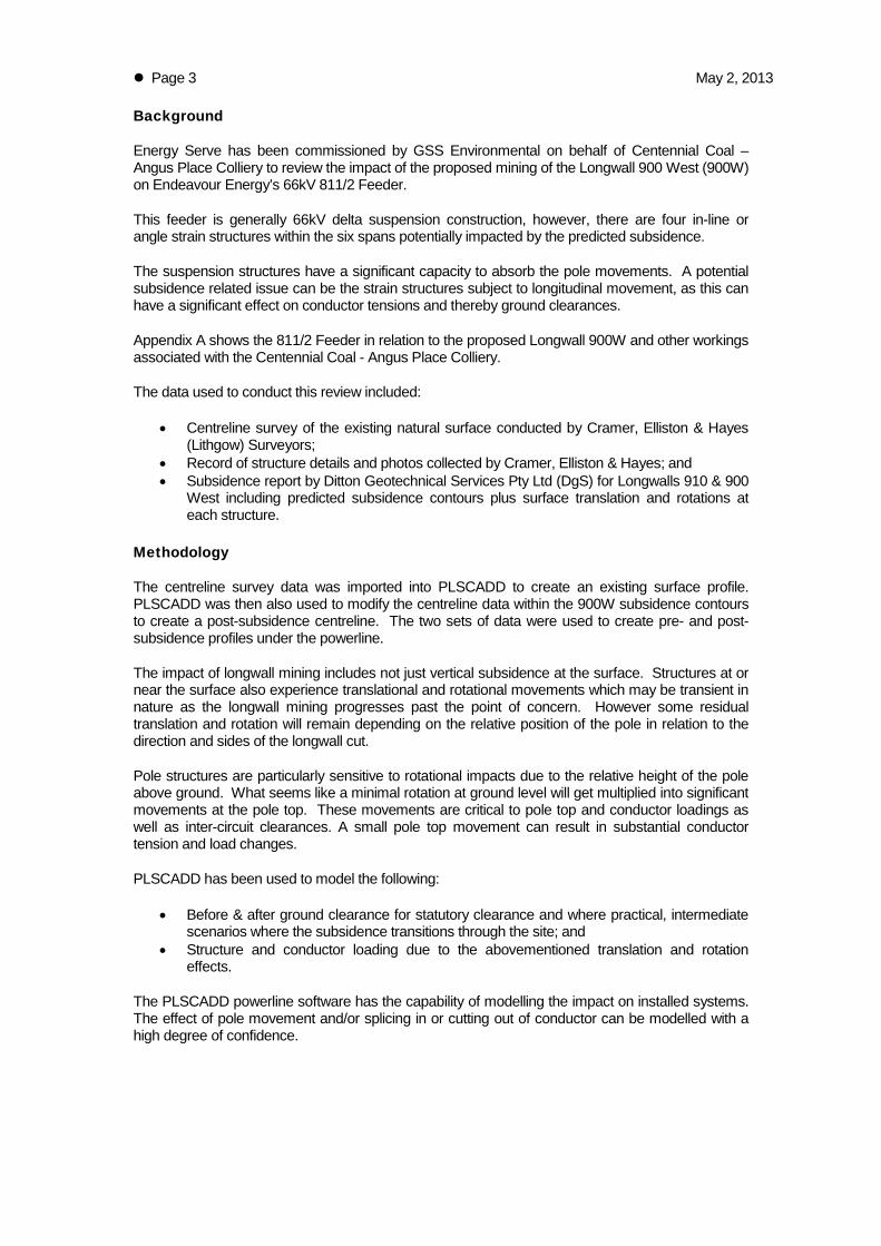
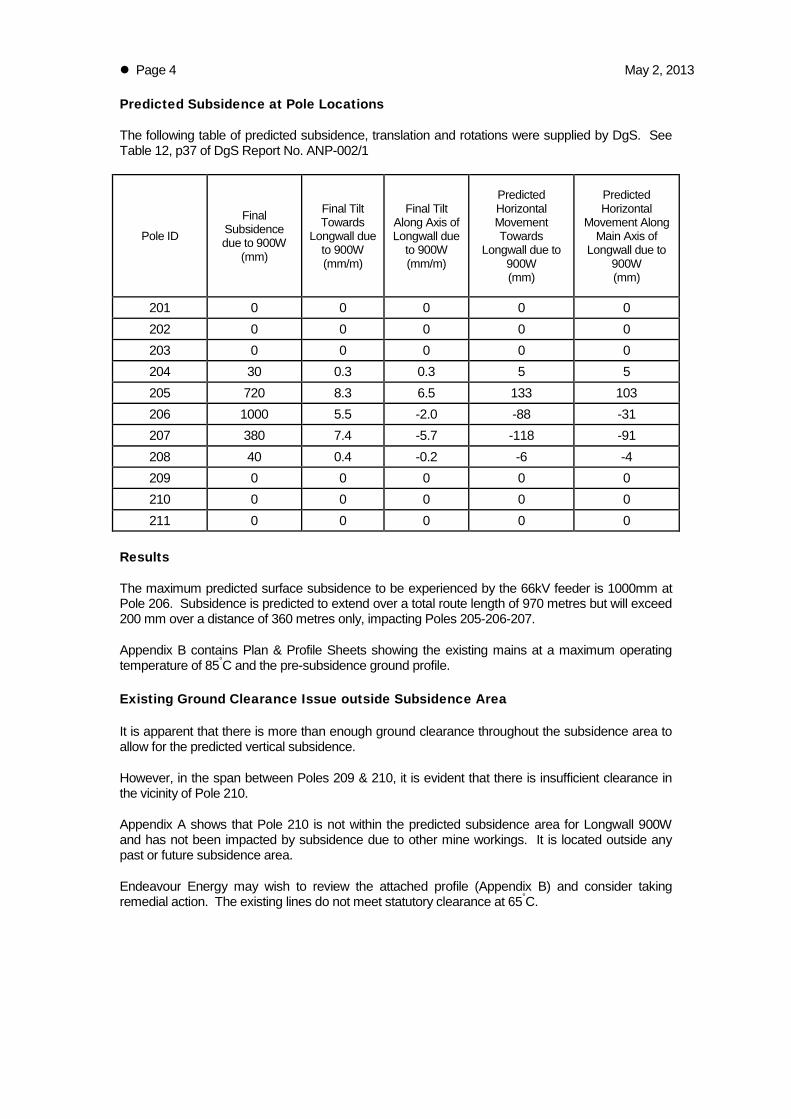

Jemtom Pty Ltd ta Energy Serve bull ABN 36 078 771 650 Suite 1 Level 1 139 Macquarie Street Dubbo NSW 2830
Tel (02) 6885 3224 bull Fax (02) 6885 3210 bull Mobile 0427 853 224
Appendix B ndash Plan amp Profile ndash Pre-subsidence
PLS
-CA
DD
Dra
win
g
-100
0
100
200
300
400
500
600
700
800
900
1000
1100
1115
1120
1125
1130
1135
1140
1145
1150
1155
1160
1165
1170
1175
1180
1185
1190
1195
1200
1205
1210
1215
1115
1120
1125
1130
1135
1140
1145
1150
1155
1160
1165
1170
1175
1180
1185
1190
1195
1200
1205
1210
1215
PI 0deg0000
PI 41deg0000
PI -14deg4800
PI -16deg5400
19912 1045 Sunny 13C 02 ms
211 211_17-201pol
210 210_17-202pol
209 209_215-203pol
208 208_185-204pol
207 207_17-205pol
206 206_185-206pol
1341
3829
2207
2417
1227 9700
m
Ext
ent of su
bsi
dence
zone
66kV
PB-206
PB-207
PB-208
PB-209
PB-21
PB-211
14
15
16
17
211
210
209
208
207
206
PI 000
0deg0000
PI 13415 41deg0000
517034deg4800
110218
16deg5400
AN
GU
S P
L 6
6 2
0121101
Exi
stin
g11
12
012
Page 1
2V
ert
S
cale
Horiz
Sca
le
100
m
500
m
North
PLS
-CA
DD
Dra
win
g
1100
1200
1300
1400
1500
1600
1700
1800
1900
2000
1125
1130
1135
1140
1145
1150
1155
1160
1165
1170
1175
1180
1185
1190
1195
1200
1205
1210
1215
1220
1225
1125
1130
1135
1140
1145
1150
1155
1160
1165
1170
1175
1180
1185
1190
1195
1200
1205
1210
1215
1220
1225
PI 0deg0000
206 206_185-206pol
205 205_185-207pol
204 204_17-208pol
203 203_185-209pol
202 202_17-2010pol
201 201_17-2011pol
1124
2293
1521
1266
2347
Ext
ent of su
bsi
dence
zone
PO
WE
RL
I NE
VPB-2
03
PB-2
04
PB-2
05
PB-2
0607
PPB-2
00
PB20
1
PB-2
0235
36
37
38
206
205
204
203
202
201
PI 110218-16deg5400
PI 1957190deg0000
AN
GU
S P
L 6
6 2
0121101
Exi
stin
g11
12
012
Page 2
2V
ert
S
cale
Horiz
Sca
le
100
m
500
m
Nor
th
Page 12 May 2 2013
Appendix C ndash Plan amp Profile ndash Post-subsidence
PLS
-CA
DD
Dra
win
g
-100
0
100
200
300
400
500
600
700
800
900
1000
1100
1115
1120
1125
1130
1135
1140
1145
1150
1155
1160
1165
1170
1175
1180
1185
1190
1195
1200
1205
1210
1215
1115
1120
1125
1130
1135
1140
1145
1150
1155
1160
1165
1170
1175
1180
1185
1190
1195
1200
1205
1210
1215
PI 0deg0000
PI 41deg0000
PI -14deg4800
PI -16deg5400
19912 1045 Sunny 13C 02 ms
211 211_17-201pol
210 210_17-202pol
209 209_215-203pol
208 208_185-204pol
207 207_17-205pol
206 206_185-206pol
1341
3829
2207
2417
1227 9700
m
Ext
ent of su
bsi
dence
zone
66kV
PB-206
PB-207
PB-208
PB-209
PB-21
PB-211
14
15
16
17
211
210
209
208
207
206
PI 000
0deg0000
PI 13415 41deg0000
517034deg4800
110218
16deg5400
AN
GU
S P
L 6
6 2
0121101
Post
subs
+ p
ole
mvt
s11
12
012
Page 1
2V
ert
S
cale
Horiz
Sca
le
100
m
500
m
North
PLS
-CA
DD
Dra
win
g
1100
1200
1300
1400
1500
1600
1700
1800
1900
2000
1125
1130
1135
1140
1145
1150
1155
1160
1165
1170
1175
1180
1185
1190
1195
1200
1205
1210
1215
1220
1225
1125
1130
1135
1140
1145
1150
1155
1160
1165
1170
1175
1180
1185
1190
1195
1200
1205
1210
1215
1220
1225
PI 0deg0000
206 206_185-206pol
205 205_185-20_subs7pol
204 204_17-208pol
203 203_185-209pol
202 202_17-2010pol
201 201_17-2011pol
1124
2293
1521
1266
2347
Ext
ent of su
bsi
dence
zone
PO
WE
RL
I NE
VPB-2
03
PB-2
04
PB-2
05
PB-2
0607
PPB-2
00
PB20
1
PB-2
0235
36
37
38
206
205
204
203
202
201
PI 110218-16deg5400
PI 1957190deg0000
AN
GU
S P
L 6
6 2
0121101
Post
subs
+ p
ole
mvt
s11
12
012
Page 2
2V
ert
S
cale
Horiz
Sca
le
100
m
500
m
Nor
th
Page 15 May 2 2013
Appendix D ndash Section Usage Report ndash Existing
Energy Serve
Page 11
PLS-CADD Version 1210x64 40015 PM Thursday 1 November 2012
Energy Serve
Project Name cuserskevin ruggdocumentsenergy servegss environmentalangus placeplsangus pl 66 20121101DON
Line Title Existing
Section Usage Report
Sec Cable From To Percent OK
No Name Str Str Usage NG
-----------------------------------
4 lemon 208 206 498 OK
5 lemon 206 204 489 OK
0 section violations OK
Check Section Summary
designates highest percent of allowable capacity
Sec Cable From To WC Weather Case Condition Allowable Actual Allowable Actual Allowable Actual of OK
No Name Str Str No Description of of Tension Tension Catenary Catenary Allowable or
No No Ultimate Ultimate (N) (N) (m) (m) Capacity NG
-------------------------------------------------------------------------------------------------------------------------------------
4 lemon 208 206 7 Limit 1000 Initial RS 700 348 313862 13423 498 OK
5 lemon 206 204 7 Limit 1000 Initial RS 700 343 308671 13242 489 OK
Page 17 May 2 2013
Appendix E ndash Section Usage Report ndash Post-subsidence
Energy Serve
Page 11
PLS-CADD Version 1210x64 35823 PM Thursday 1 November 2012
Energy Serve
Project Name cuserskevin ruggdocumentsenergy servegss environmentalangus placeplsangus pl 66 20121101DON
Line Title Post subs + pole mvts
Section Usage Report
Sec Cable From To Percent OK
No Name Str Str Usage NG
-----------------------------------
4 lemon 208 206 539 OK
5 lemon 206 204 519 OK
0 section violations OK
Check Section Summary
designates highest percent of allowable capacity
Sec Cable From To WC Weather Case Condition Allowable Actual Allowable Actual Allowable Actual of OK
No Name Str Str No Description of of Tension Tension Catenary Catenary Allowable or
No No Ultimate Ultimate (N) (N) (m) (m) Capacity NG
-------------------------------------------------------------------------------------------------------------------------------------
4 lemon 208 206 7 Limit 1000 Initial FE 700 378 340206 14565 539 OK
5 lemon 206 204 7 Limit 1000 Initial FE 700 363 327374 14052 519 OK
Page 19 May 2 2013
Appendix F ndash Structure Usage Report ndash Existing
Energy Serve
Page 14
PLS-CADD Version 1210x64 40113 PM Thursday 1 November 2012
Energy Serve
Project Name cuserskevin ruggdocumentsenergy servegss environmentalangus placeplsangus pl 66 20121101DON
Line Title Existing
Structure Locations and Usage Report
Structure Structure Station Line --Constraints--- Structure Insulator Minimum Pole OK
Number Name Angle Prohib Req Extra Strength Swing Required Tip or
Zone Pos Cost Usage Usage Vertical Deflection NG
Load Usage
(m) (deg) () () (Uplift) ()
---------------------------------------------------------------------------------------------------------
208 208_185-204pol 73777 000 0 737 00 OK OK
207 207_17-205pol 97945 000 0 531 320 OK OK
206 206_185-206pol 110218 -1690 Y 0 698 00 OK OK
205 205_185-207pol 121453 000 0 432 495 OK OK
204 204_17-208pol 144382 000 0 694 00 OK OK
0 structure violations 0 structure warnings OK
Energy Serve
Page 24
Multiple Structure Suspension Insulator Swing Angles and V-String Load Angles
Str Set Phase Swing Weather Wire Min Max Min Max of OK
Cond Case Condition Allowed Allowed Calc Calc Allowed
Description (deg) (deg) (deg) (deg) Swing
-----------------------------------------------------------------------------------------------------
207 3 1 1 Hot 85 Creep RS -900 900 -40 -40 45 OK
2 1 Hot 85 Creep RS -900 900 27 27 30 OK
3 1 Hot 85 Creep RS -900 900 -26 -26 29 OK
1 2 Swing 210 Initial RS -900 900 -166 57 184 OK
2 2 Swing 210 Initial RS -900 900 -78 153 170 OK
3 2 Swing 210 Initial RS -900 900 -142 72 158 OK
1 3 Swing 500 Initial RS -900 900 -288 188 320 OK
2 3 Swing 500 Initial RS -900 900 -212 280 311 OK
3 3 Swing 500 Initial RS -900 900 -261 197 290 OK
1 4 Cold 0 Initial RS -900 900 -59 -59 65 OK
2 4 Cold 0 Initial RS -900 900 40 40 45 OK
3 4 Cold 0 Initial RS -900 900 -37 -37 42 OK
205 1 1 Hot 85 Creep RS -900 900 -64 -64 71 OK
2 1 Hot 85 Creep RS -900 900 45 45 50 OK
3 1 Hot 85 Creep RS -900 900 -41 -41 46 OK
1 2 Swing 210 Initial RS -900 900 -276 81 307 OK
2 2 Swing 210 Initial RS -900 900 -123 263 293 OK
3 2 Swing 210 Initial RS -900 900 -231 107 257 OK
1 3 Swing 500 Initial RS -900 900 -444 295 493 OK
2 3 Swing 500 Initial RS -900 900 -343 446 495 OK
3 3 Swing 500 Initial RS -900 900 -400 301 444 OK
1 4 Cold 0 Initial RS -900 900 -115 -115 128 OK
2 4 Cold 0 Initial RS -900 900 85 85 94 OK
3 4 Cold 0 Initial RS -900 900 -72 -72 80 OK
Energy Serve
Page 34
Multiple Structure Minimum Vertical Load (Uplift) Summary
Str Set Phase Swing Weather Wire Min Vert Vert Vert OK
Cond Case Condition Req Load Load Load
Description Vert Wind Wind Margin
Load From From
Left Right
(N) (N) (N) (N)
-----------------------------------------------------------------------------------
207 3 1 1 Hot 85 Creep RS 0 2967 2967 2967 OK
2 1 Hot 85 Creep RS 0 2901 2901 2901 OK
3 1 Hot 85 Creep RS 0 3069 3069 3069 OK
1 2 Swing 210 Initial RS 0 3982 3982 3982 OK
2 2 Swing 210 Initial RS 0 3858 3858 3858 OK
3 2 Swing 210 Initial RS 0 4172 4172 4172 OK
1 3 Swing 500 Initial RS 0 4246 4246 4246 OK
2 3 Swing 500 Initial RS 0 4107 4107 4107 OK
3 3 Swing 500 Initial RS 0 4459 4459 4459 OK
1 4 Cold 0 Initial RS 0 4175 4175 4175 OK
2 4 Cold 0 Initial RS 0 4041 4041 4041 OK
3 4 Cold 0 Initial RS 0 4382 4382 4382 OK
205 1 1 Hot 85 Creep RS 0 1936 1936 1936 OK
2 1 Hot 85 Creep RS 0 1853 1853 1853 OK
3 1 Hot 85 Creep RS 0 2033 2033 2033 OK
1 2 Swing 210 Initial RS 0 2173 2173 2173 OK
2 2 Swing 210 Initial RS 0 2016 2016 2016 OK
3 2 Swing 210 Initial RS 0 2359 2359 2359 OK
1 3 Swing 500 Initial RS 0 2231 2231 2231 OK
2 3 Swing 500 Initial RS 0 2056 2056 2056 OK
3 3 Swing 500 Initial RS 0 2438 2438 2438 OK
1 4 Cold 0 Initial RS 0 2220 2220 2220 OK
2 4 Cold 0 Initial RS 0 2049 2049 2049 OK
3 4 Cold 0 Initial RS 0 2424 2424 2424 OK
Energy Serve
Page 44
Page 24 May 2 2013
Appendix G ndash Structure Usage Report ndash Post-subsidence
Energy Serve
Page 14
PLS-CADD Version 1210x64 40449 PM Thursday 1 November 2012
Energy Serve
Project Name cuserskevin ruggdocumentsenergy servegss environmentalangus placeplsangus pl 66 20121101DON
Line Title Post subs + pole mvts
Structure Locations and Usage Report
Structure Structure Station Line --Constraints--- Structure Insulator Minimum Pole OK
Number Name Angle Prohib Req Extra Strength Swing Required Tip or
Zone Pos Cost Usage Usage Vertical Deflection NG
Load Usage
(m) (deg) () () (Uplift) ()
--------------------------------------------------------------------------------------------------------------
208 208_185-204pol 73777 000 0 747 00 OK OK
207 207_17-20_subs5pol 97945 000 0 606 288 OK OK
206 206_185-20_subs6pol 110218 -1690 Y 0 728 00 OK OK
205 205_185-20_subs7pol 121453 000 0 447 449 OK OK
204 204_17-208pol 144382 000 0 714 00 OK OK
0 structure violations 0 structure warnings OK
Energy Serve
Page 24
Multiple Structure Suspension Insulator Swing Angles and V-String Load Angles
Str Set Phase Swing Weather Wire Min Max Min Max of OK
Cond Case Condition Allowed Allowed Calc Calc Allowed
Description (deg) (deg) (deg) (deg) Swing
-----------------------------------------------------------------------------------------------------
207 3 1 1 Hot 85 Creep FE -900 900 -37 -37 41 OK
2 1 Hot 85 Creep FE -900 900 29 29 32 OK
3 1 Hot 85 Creep FE -900 900 -23 -23 26 OK
1 2 Swing 210 Initial FE -900 900 -149 49 165 OK
2 2 Swing 210 Initial FE -900 900 -62 141 157 OK
3 2 Swing 210 Initial FE -900 900 -126 64 140 OK
1 3 Swing 500 Initial FE -900 900 -259 165 288 OK
2 3 Swing 500 Initial FE -900 900 -181 255 284 OK
3 3 Swing 500 Initial FE -900 900 -234 174 260 OK
1 4 Cold 0 Initial FE -900 900 -53 -53 59 OK
2 4 Cold 0 Initial FE -900 900 42 42 47 OK
3 4 Cold 0 Initial FE -900 900 -33 -33 37 OK
205 1 1 Hot 85 Creep FE -900 900 -65 -65 72 OK
2 1 Hot 85 Creep FE -900 900 34 34 38 OK
3 1 Hot 85 Creep FE -900 900 -42 -42 47 OK
1 2 Swing 210 Initial FE -900 900 -253 52 281 OK
2 2 Swing 210 Initial FE -900 900 -113 224 249 OK
3 2 Swing 210 Initial FE -900 900 -212 84 236 OK
1 3 Swing 500 Initial FE -900 900 -404 237 449 OK
2 3 Swing 500 Initial FE -900 900 -304 393 437 OK
3 3 Swing 500 Initial FE -900 900 -365 257 406 OK
1 4 Cold 0 Initial FE -900 900 -115 -115 127 OK
2 4 Cold 0 Initial FE -900 900 65 65 72 OK
3 4 Cold 0 Initial FE -900 900 -73 -73 81 OK
Energy Serve
Page 34
Multiple Structure Minimum Vertical Load (Uplift) Summary
Str Set Phase Swing Weather Wire Min Vert Vert Vert OK
Cond Case Condition Req Load Load Load
Description Vert Wind Wind Margin
Load From From
Left Right
(N) (N) (N) (N)
-----------------------------------------------------------------------------------
207 3 1 1 Hot 85 Creep RS 0 3066 3066 3066 OK
2 1 Hot 85 Creep RS 0 3006 3006 3006 OK
3 1 Hot 85 Creep RS 0 3179 3179 3179 OK
1 2 Swing 210 Initial RS 0 4193 4186 4186 OK
2 2 Swing 210 Initial RS 0 4087 4086 4086 OK
3 2 Swing 210 Initial RS 0 4426 4419 4419 OK
1 3 Swing 500 Initial RS 0 4488 4474 4474 OK
2 3 Swing 500 Initial RS 0 4364 4361 4361 OK
3 3 Swing 500 Initial RS 0 4742 4726 4726 OK
1 4 Cold 0 Initial RS 0 4388 4388 4388 OK
2 4 Cold 0 Initial RS 0 4275 4275 4275 OK
3 4 Cold 0 Initial RS 0 4640 4640 4640 OK
205 1 1 Hot 85 Creep RS 0 1968 1968 1968 OK
2 1 Hot 85 Creep RS 0 1887 1887 1887 OK
3 1 Hot 85 Creep RS 0 2061 2061 2061 OK
1 2 Swing 210 Initial RS 0 2224 2245 2224 OK
2 2 Swing 210 Initial RS 0 2074 2059 2059 OK
3 2 Swing 210 Initial RS 0 2401 2412 2401 OK
1 3 Swing 500 Initial RS 0 2315 2353 2315 OK
2 3 Swing 500 Initial RS 0 2170 2142 2142 OK
3 3 Swing 500 Initial RS 0 2518 2539 2518 OK
1 4 Cold 0 Initial RS 0 2274 2274 2274 OK
2 4 Cold 0 Initial RS 0 2087 2087 2087 OK
3 4 Cold 0 Initial RS 0 2461 2461 2461 OK
Energy Serve
Page 44
Page 29 May 2 2013
Appendix H ndash Endeavour Energy ndash David Mate ndash Email 25 March 2013
From David MateTo Kevin RuggSubject RE Centennial Coal - Angus Place - Subsidence Impact of Endeavour Energy 66kV Feeder 811Date Monday 25 March 2013 120800 PMAttachments image001png
Hi Kevin Based on the information in the report I have no issues in relation to the subsidence at AngusPlace
RegardsDavid David MateOverhead amp Underground Mains Manager ( 02 9853 6010Egrave 0413 227 4997 02 9853 6021 davidmateendeavourenergycomau 51 Huntingwood Drive Huntingwood NSW 2148 wwwendeavourenergycomau
From Kevin Rugg [mailtokevinenergyservecomau] Sent Monday 25 March 2013 1145 AMTo David MateSubject RE Centennial Coal - Angus Place - Subsidence Impact of Endeavour Energy 66kV Feeder811 Thanks David Thatrsquos all good but I am trying to find someone within Endeavour who will give us the all clear onthe subsidence impact assessment Cheers Kevin Rugg kevinenergyservecomau Energy ServeJemtom Pty Ltd(ABN 36 078 771 650)Ph (02) 6885 3224Fax (02) 6885 3210Mob 0427 853 224 This message is intended for the addressee named and may contain confidential information If you are not the intended

PLS
-CA
DD
Dra
win
g
-100
0
100
200
300
400
500
600
700
800
900
1000
1100
1115
1120
1125
1130
1135
1140
1145
1150
1155
1160
1165
1170
1175
1180
1185
1190
1195
1200
1205
1210
1215
1115
1120
1125
1130
1135
1140
1145
1150
1155
1160
1165
1170
1175
1180
1185
1190
1195
1200
1205
1210
1215
PI 0deg0000
PI 41deg0000
PI -14deg4800
PI -16deg5400
19912 1045 Sunny 13C 02 ms
211 211_17-201pol
210 210_17-202pol
209 209_215-203pol
208 208_185-204pol
207 207_17-205pol
206 206_185-206pol
1341
3829
2207
2417
1227 9700
m
Ext
ent of su
bsi
dence
zone
66kV
PB-206
PB-207
PB-208
PB-209
PB-21
PB-211
14
15
16
17
211
210
209
208
207
206
PI 000
0deg0000
PI 13415 41deg0000
517034deg4800
110218
16deg5400
AN
GU
S P
L 6
6 2
0121101
Exi
stin
g11
12
012
Page 1
2V
ert
S
cale
Horiz
Sca
le
100
m
500
m
North
PLS
-CA
DD
Dra
win
g
1100
1200
1300
1400
1500
1600
1700
1800
1900
2000
1125
1130
1135
1140
1145
1150
1155
1160
1165
1170
1175
1180
1185
1190
1195
1200
1205
1210
1215
1220
1225
1125
1130
1135
1140
1145
1150
1155
1160
1165
1170
1175
1180
1185
1190
1195
1200
1205
1210
1215
1220
1225
PI 0deg0000
206 206_185-206pol
205 205_185-207pol
204 204_17-208pol
203 203_185-209pol
202 202_17-2010pol
201 201_17-2011pol
1124
2293
1521
1266
2347
Ext
ent of su
bsi
dence
zone
PO
WE
RL
I NE
VPB-2
03
PB-2
04
PB-2
05
PB-2
0607
PPB-2
00
PB20
1
PB-2
0235
36
37
38
206
205
204
203
202
201
PI 110218-16deg5400
PI 1957190deg0000
AN
GU
S P
L 6
6 2
0121101
Exi
stin
g11
12
012
Page 2
2V
ert
S
cale
Horiz
Sca
le
100
m
500
m
Nor
th
Page 12 May 2 2013
Appendix C ndash Plan amp Profile ndash Post-subsidence
PLS
-CA
DD
Dra
win
g
-100
0
100
200
300
400
500
600
700
800
900
1000
1100
1115
1120
1125
1130
1135
1140
1145
1150
1155
1160
1165
1170
1175
1180
1185
1190
1195
1200
1205
1210
1215
1115
1120
1125
1130
1135
1140
1145
1150
1155
1160
1165
1170
1175
1180
1185
1190
1195
1200
1205
1210
1215
PI 0deg0000
PI 41deg0000
PI -14deg4800
PI -16deg5400
19912 1045 Sunny 13C 02 ms
211 211_17-201pol
210 210_17-202pol
209 209_215-203pol
208 208_185-204pol
207 207_17-205pol
206 206_185-206pol
1341
3829
2207
2417
1227 9700
m
Ext
ent of su
bsi
dence
zone
66kV
PB-206
PB-207
PB-208
PB-209
PB-21
PB-211
14
15
16
17
211
210
209
208
207
206
PI 000
0deg0000
PI 13415 41deg0000
517034deg4800
110218
16deg5400
AN
GU
S P
L 6
6 2
0121101
Post
subs
+ p
ole
mvt
s11
12
012
Page 1
2V
ert
S
cale
Horiz
Sca
le
100
m
500
m
North
PLS
-CA
DD
Dra
win
g
1100
1200
1300
1400
1500
1600
1700
1800
1900
2000
1125
1130
1135
1140
1145
1150
1155
1160
1165
1170
1175
1180
1185
1190
1195
1200
1205
1210
1215
1220
1225
1125
1130
1135
1140
1145
1150
1155
1160
1165
1170
1175
1180
1185
1190
1195
1200
1205
1210
1215
1220
1225
PI 0deg0000
206 206_185-206pol
205 205_185-20_subs7pol
204 204_17-208pol
203 203_185-209pol
202 202_17-2010pol
201 201_17-2011pol
1124
2293
1521
1266
2347
Ext
ent of su
bsi
dence
zone
PO
WE
RL
I NE
VPB-2
03
PB-2
04
PB-2
05
PB-2
0607
PPB-2
00
PB20
1
PB-2
0235
36
37
38
206
205
204
203
202
201
PI 110218-16deg5400
PI 1957190deg0000
AN
GU
S P
L 6
6 2
0121101
Post
subs
+ p
ole
mvt
s11
12
012
Page 2
2V
ert
S
cale
Horiz
Sca
le
100
m
500
m
Nor
th
Page 15 May 2 2013
Appendix D ndash Section Usage Report ndash Existing
Energy Serve
Page 11
PLS-CADD Version 1210x64 40015 PM Thursday 1 November 2012
Energy Serve
Project Name cuserskevin ruggdocumentsenergy servegss environmentalangus placeplsangus pl 66 20121101DON
Line Title Existing
Section Usage Report
Sec Cable From To Percent OK
No Name Str Str Usage NG
-----------------------------------
4 lemon 208 206 498 OK
5 lemon 206 204 489 OK
0 section violations OK
Check Section Summary
designates highest percent of allowable capacity
Sec Cable From To WC Weather Case Condition Allowable Actual Allowable Actual Allowable Actual of OK
No Name Str Str No Description of of Tension Tension Catenary Catenary Allowable or
No No Ultimate Ultimate (N) (N) (m) (m) Capacity NG
-------------------------------------------------------------------------------------------------------------------------------------
4 lemon 208 206 7 Limit 1000 Initial RS 700 348 313862 13423 498 OK
5 lemon 206 204 7 Limit 1000 Initial RS 700 343 308671 13242 489 OK
Page 17 May 2 2013
Appendix E ndash Section Usage Report ndash Post-subsidence
Energy Serve
Page 11
PLS-CADD Version 1210x64 35823 PM Thursday 1 November 2012
Energy Serve
Project Name cuserskevin ruggdocumentsenergy servegss environmentalangus placeplsangus pl 66 20121101DON
Line Title Post subs + pole mvts
Section Usage Report
Sec Cable From To Percent OK
No Name Str Str Usage NG
-----------------------------------
4 lemon 208 206 539 OK
5 lemon 206 204 519 OK
0 section violations OK
Check Section Summary
designates highest percent of allowable capacity
Sec Cable From To WC Weather Case Condition Allowable Actual Allowable Actual Allowable Actual of OK
No Name Str Str No Description of of Tension Tension Catenary Catenary Allowable or
No No Ultimate Ultimate (N) (N) (m) (m) Capacity NG
-------------------------------------------------------------------------------------------------------------------------------------
4 lemon 208 206 7 Limit 1000 Initial FE 700 378 340206 14565 539 OK
5 lemon 206 204 7 Limit 1000 Initial FE 700 363 327374 14052 519 OK
Page 19 May 2 2013
Appendix F ndash Structure Usage Report ndash Existing
Energy Serve
Page 14
PLS-CADD Version 1210x64 40113 PM Thursday 1 November 2012
Energy Serve
Project Name cuserskevin ruggdocumentsenergy servegss environmentalangus placeplsangus pl 66 20121101DON
Line Title Existing
Structure Locations and Usage Report
Structure Structure Station Line --Constraints--- Structure Insulator Minimum Pole OK
Number Name Angle Prohib Req Extra Strength Swing Required Tip or
Zone Pos Cost Usage Usage Vertical Deflection NG
Load Usage
(m) (deg) () () (Uplift) ()
---------------------------------------------------------------------------------------------------------
208 208_185-204pol 73777 000 0 737 00 OK OK
207 207_17-205pol 97945 000 0 531 320 OK OK
206 206_185-206pol 110218 -1690 Y 0 698 00 OK OK
205 205_185-207pol 121453 000 0 432 495 OK OK
204 204_17-208pol 144382 000 0 694 00 OK OK
0 structure violations 0 structure warnings OK
Energy Serve
Page 24
Multiple Structure Suspension Insulator Swing Angles and V-String Load Angles
Str Set Phase Swing Weather Wire Min Max Min Max of OK
Cond Case Condition Allowed Allowed Calc Calc Allowed
Description (deg) (deg) (deg) (deg) Swing
-----------------------------------------------------------------------------------------------------
207 3 1 1 Hot 85 Creep RS -900 900 -40 -40 45 OK
2 1 Hot 85 Creep RS -900 900 27 27 30 OK
3 1 Hot 85 Creep RS -900 900 -26 -26 29 OK
1 2 Swing 210 Initial RS -900 900 -166 57 184 OK
2 2 Swing 210 Initial RS -900 900 -78 153 170 OK
3 2 Swing 210 Initial RS -900 900 -142 72 158 OK
1 3 Swing 500 Initial RS -900 900 -288 188 320 OK
2 3 Swing 500 Initial RS -900 900 -212 280 311 OK
3 3 Swing 500 Initial RS -900 900 -261 197 290 OK
1 4 Cold 0 Initial RS -900 900 -59 -59 65 OK
2 4 Cold 0 Initial RS -900 900 40 40 45 OK
3 4 Cold 0 Initial RS -900 900 -37 -37 42 OK
205 1 1 Hot 85 Creep RS -900 900 -64 -64 71 OK
2 1 Hot 85 Creep RS -900 900 45 45 50 OK
3 1 Hot 85 Creep RS -900 900 -41 -41 46 OK
1 2 Swing 210 Initial RS -900 900 -276 81 307 OK
2 2 Swing 210 Initial RS -900 900 -123 263 293 OK
3 2 Swing 210 Initial RS -900 900 -231 107 257 OK
1 3 Swing 500 Initial RS -900 900 -444 295 493 OK
2 3 Swing 500 Initial RS -900 900 -343 446 495 OK
3 3 Swing 500 Initial RS -900 900 -400 301 444 OK
1 4 Cold 0 Initial RS -900 900 -115 -115 128 OK
2 4 Cold 0 Initial RS -900 900 85 85 94 OK
3 4 Cold 0 Initial RS -900 900 -72 -72 80 OK
Energy Serve
Page 34
Multiple Structure Minimum Vertical Load (Uplift) Summary
Str Set Phase Swing Weather Wire Min Vert Vert Vert OK
Cond Case Condition Req Load Load Load
Description Vert Wind Wind Margin
Load From From
Left Right
(N) (N) (N) (N)
-----------------------------------------------------------------------------------
207 3 1 1 Hot 85 Creep RS 0 2967 2967 2967 OK
2 1 Hot 85 Creep RS 0 2901 2901 2901 OK
3 1 Hot 85 Creep RS 0 3069 3069 3069 OK
1 2 Swing 210 Initial RS 0 3982 3982 3982 OK
2 2 Swing 210 Initial RS 0 3858 3858 3858 OK
3 2 Swing 210 Initial RS 0 4172 4172 4172 OK
1 3 Swing 500 Initial RS 0 4246 4246 4246 OK
2 3 Swing 500 Initial RS 0 4107 4107 4107 OK
3 3 Swing 500 Initial RS 0 4459 4459 4459 OK
1 4 Cold 0 Initial RS 0 4175 4175 4175 OK
2 4 Cold 0 Initial RS 0 4041 4041 4041 OK
3 4 Cold 0 Initial RS 0 4382 4382 4382 OK
205 1 1 Hot 85 Creep RS 0 1936 1936 1936 OK
2 1 Hot 85 Creep RS 0 1853 1853 1853 OK
3 1 Hot 85 Creep RS 0 2033 2033 2033 OK
1 2 Swing 210 Initial RS 0 2173 2173 2173 OK
2 2 Swing 210 Initial RS 0 2016 2016 2016 OK
3 2 Swing 210 Initial RS 0 2359 2359 2359 OK
1 3 Swing 500 Initial RS 0 2231 2231 2231 OK
2 3 Swing 500 Initial RS 0 2056 2056 2056 OK
3 3 Swing 500 Initial RS 0 2438 2438 2438 OK
1 4 Cold 0 Initial RS 0 2220 2220 2220 OK
2 4 Cold 0 Initial RS 0 2049 2049 2049 OK
3 4 Cold 0 Initial RS 0 2424 2424 2424 OK
Energy Serve
Page 44
Page 24 May 2 2013
Appendix G ndash Structure Usage Report ndash Post-subsidence
Energy Serve
Page 14
PLS-CADD Version 1210x64 40449 PM Thursday 1 November 2012
Energy Serve
Project Name cuserskevin ruggdocumentsenergy servegss environmentalangus placeplsangus pl 66 20121101DON
Line Title Post subs + pole mvts
Structure Locations and Usage Report
Structure Structure Station Line --Constraints--- Structure Insulator Minimum Pole OK
Number Name Angle Prohib Req Extra Strength Swing Required Tip or
Zone Pos Cost Usage Usage Vertical Deflection NG
Load Usage
(m) (deg) () () (Uplift) ()
--------------------------------------------------------------------------------------------------------------
208 208_185-204pol 73777 000 0 747 00 OK OK
207 207_17-20_subs5pol 97945 000 0 606 288 OK OK
206 206_185-20_subs6pol 110218 -1690 Y 0 728 00 OK OK
205 205_185-20_subs7pol 121453 000 0 447 449 OK OK
204 204_17-208pol 144382 000 0 714 00 OK OK
0 structure violations 0 structure warnings OK
Energy Serve
Page 24
Multiple Structure Suspension Insulator Swing Angles and V-String Load Angles
Str Set Phase Swing Weather Wire Min Max Min Max of OK
Cond Case Condition Allowed Allowed Calc Calc Allowed
Description (deg) (deg) (deg) (deg) Swing
-----------------------------------------------------------------------------------------------------
207 3 1 1 Hot 85 Creep FE -900 900 -37 -37 41 OK
2 1 Hot 85 Creep FE -900 900 29 29 32 OK
3 1 Hot 85 Creep FE -900 900 -23 -23 26 OK
1 2 Swing 210 Initial FE -900 900 -149 49 165 OK
2 2 Swing 210 Initial FE -900 900 -62 141 157 OK
3 2 Swing 210 Initial FE -900 900 -126 64 140 OK
1 3 Swing 500 Initial FE -900 900 -259 165 288 OK
2 3 Swing 500 Initial FE -900 900 -181 255 284 OK
3 3 Swing 500 Initial FE -900 900 -234 174 260 OK
1 4 Cold 0 Initial FE -900 900 -53 -53 59 OK
2 4 Cold 0 Initial FE -900 900 42 42 47 OK
3 4 Cold 0 Initial FE -900 900 -33 -33 37 OK
205 1 1 Hot 85 Creep FE -900 900 -65 -65 72 OK
2 1 Hot 85 Creep FE -900 900 34 34 38 OK
3 1 Hot 85 Creep FE -900 900 -42 -42 47 OK
1 2 Swing 210 Initial FE -900 900 -253 52 281 OK
2 2 Swing 210 Initial FE -900 900 -113 224 249 OK
3 2 Swing 210 Initial FE -900 900 -212 84 236 OK
1 3 Swing 500 Initial FE -900 900 -404 237 449 OK
2 3 Swing 500 Initial FE -900 900 -304 393 437 OK
3 3 Swing 500 Initial FE -900 900 -365 257 406 OK
1 4 Cold 0 Initial FE -900 900 -115 -115 127 OK
2 4 Cold 0 Initial FE -900 900 65 65 72 OK
3 4 Cold 0 Initial FE -900 900 -73 -73 81 OK
Energy Serve
Page 34
Multiple Structure Minimum Vertical Load (Uplift) Summary
Str Set Phase Swing Weather Wire Min Vert Vert Vert OK
Cond Case Condition Req Load Load Load
Description Vert Wind Wind Margin
Load From From
Left Right
(N) (N) (N) (N)
-----------------------------------------------------------------------------------
207 3 1 1 Hot 85 Creep RS 0 3066 3066 3066 OK
2 1 Hot 85 Creep RS 0 3006 3006 3006 OK
3 1 Hot 85 Creep RS 0 3179 3179 3179 OK
1 2 Swing 210 Initial RS 0 4193 4186 4186 OK
2 2 Swing 210 Initial RS 0 4087 4086 4086 OK
3 2 Swing 210 Initial RS 0 4426 4419 4419 OK
1 3 Swing 500 Initial RS 0 4488 4474 4474 OK
2 3 Swing 500 Initial RS 0 4364 4361 4361 OK
3 3 Swing 500 Initial RS 0 4742 4726 4726 OK
1 4 Cold 0 Initial RS 0 4388 4388 4388 OK
2 4 Cold 0 Initial RS 0 4275 4275 4275 OK
3 4 Cold 0 Initial RS 0 4640 4640 4640 OK
205 1 1 Hot 85 Creep RS 0 1968 1968 1968 OK
2 1 Hot 85 Creep RS 0 1887 1887 1887 OK
3 1 Hot 85 Creep RS 0 2061 2061 2061 OK
1 2 Swing 210 Initial RS 0 2224 2245 2224 OK
2 2 Swing 210 Initial RS 0 2074 2059 2059 OK
3 2 Swing 210 Initial RS 0 2401 2412 2401 OK
1 3 Swing 500 Initial RS 0 2315 2353 2315 OK
2 3 Swing 500 Initial RS 0 2170 2142 2142 OK
3 3 Swing 500 Initial RS 0 2518 2539 2518 OK
1 4 Cold 0 Initial RS 0 2274 2274 2274 OK
2 4 Cold 0 Initial RS 0 2087 2087 2087 OK
3 4 Cold 0 Initial RS 0 2461 2461 2461 OK
Energy Serve
Page 44
Page 29 May 2 2013
Appendix H ndash Endeavour Energy ndash David Mate ndash Email 25 March 2013
From David MateTo Kevin RuggSubject RE Centennial Coal - Angus Place - Subsidence Impact of Endeavour Energy 66kV Feeder 811Date Monday 25 March 2013 120800 PMAttachments image001png
Hi Kevin Based on the information in the report I have no issues in relation to the subsidence at AngusPlace
RegardsDavid David MateOverhead amp Underground Mains Manager ( 02 9853 6010Egrave 0413 227 4997 02 9853 6021 davidmateendeavourenergycomau 51 Huntingwood Drive Huntingwood NSW 2148 wwwendeavourenergycomau
From Kevin Rugg [mailtokevinenergyservecomau] Sent Monday 25 March 2013 1145 AMTo David MateSubject RE Centennial Coal - Angus Place - Subsidence Impact of Endeavour Energy 66kV Feeder811 Thanks David Thatrsquos all good but I am trying to find someone within Endeavour who will give us the all clear onthe subsidence impact assessment Cheers Kevin Rugg kevinenergyservecomau Energy ServeJemtom Pty Ltd(ABN 36 078 771 650)Ph (02) 6885 3224Fax (02) 6885 3210Mob 0427 853 224 This message is intended for the addressee named and may contain confidential information If you are not the intended

PLS
-CA
DD
Dra
win
g
1100
1200
1300
1400
1500
1600
1700
1800
1900
2000
1125
1130
1135
1140
1145
1150
1155
1160
1165
1170
1175
1180
1185
1190
1195
1200
1205
1210
1215
1220
1225
1125
1130
1135
1140
1145
1150
1155
1160
1165
1170
1175
1180
1185
1190
1195
1200
1205
1210
1215
1220
1225
PI 0deg0000
206 206_185-206pol
205 205_185-207pol
204 204_17-208pol
203 203_185-209pol
202 202_17-2010pol
201 201_17-2011pol
1124
2293
1521
1266
2347
Ext
ent of su
bsi
dence
zone
PO
WE
RL
I NE
VPB-2
03
PB-2
04
PB-2
05
PB-2
0607
PPB-2
00
PB20
1
PB-2
0235
36
37
38
206
205
204
203
202
201
PI 110218-16deg5400
PI 1957190deg0000
AN
GU
S P
L 6
6 2
0121101
Exi
stin
g11
12
012
Page 2
2V
ert
S
cale
Horiz
Sca
le
100
m
500
m
Nor
th
Page 12 May 2 2013
Appendix C ndash Plan amp Profile ndash Post-subsidence
PLS
-CA
DD
Dra
win
g
-100
0
100
200
300
400
500
600
700
800
900
1000
1100
1115
1120
1125
1130
1135
1140
1145
1150
1155
1160
1165
1170
1175
1180
1185
1190
1195
1200
1205
1210
1215
1115
1120
1125
1130
1135
1140
1145
1150
1155
1160
1165
1170
1175
1180
1185
1190
1195
1200
1205
1210
1215
PI 0deg0000
PI 41deg0000
PI -14deg4800
PI -16deg5400
19912 1045 Sunny 13C 02 ms
211 211_17-201pol
210 210_17-202pol
209 209_215-203pol
208 208_185-204pol
207 207_17-205pol
206 206_185-206pol
1341
3829
2207
2417
1227 9700
m
Ext
ent of su
bsi
dence
zone
66kV
PB-206
PB-207
PB-208
PB-209
PB-21
PB-211
14
15
16
17
211
210
209
208
207
206
PI 000
0deg0000
PI 13415 41deg0000
517034deg4800
110218
16deg5400
AN
GU
S P
L 6
6 2
0121101
Post
subs
+ p
ole
mvt
s11
12
012
Page 1
2V
ert
S
cale
Horiz
Sca
le
100
m
500
m
North
PLS
-CA
DD
Dra
win
g
1100
1200
1300
1400
1500
1600
1700
1800
1900
2000
1125
1130
1135
1140
1145
1150
1155
1160
1165
1170
1175
1180
1185
1190
1195
1200
1205
1210
1215
1220
1225
1125
1130
1135
1140
1145
1150
1155
1160
1165
1170
1175
1180
1185
1190
1195
1200
1205
1210
1215
1220
1225
PI 0deg0000
206 206_185-206pol
205 205_185-20_subs7pol
204 204_17-208pol
203 203_185-209pol
202 202_17-2010pol
201 201_17-2011pol
1124
2293
1521
1266
2347
Ext
ent of su
bsi
dence
zone
PO
WE
RL
I NE
VPB-2
03
PB-2
04
PB-2
05
PB-2
0607
PPB-2
00
PB20
1
PB-2
0235
36
37
38
206
205
204
203
202
201
PI 110218-16deg5400
PI 1957190deg0000
AN
GU
S P
L 6
6 2
0121101
Post
subs
+ p
ole
mvt
s11
12
012
Page 2
2V
ert
S
cale
Horiz
Sca
le
100
m
500
m
Nor
th
Page 15 May 2 2013
Appendix D ndash Section Usage Report ndash Existing
Energy Serve
Page 11
PLS-CADD Version 1210x64 40015 PM Thursday 1 November 2012
Energy Serve
Project Name cuserskevin ruggdocumentsenergy servegss environmentalangus placeplsangus pl 66 20121101DON
Line Title Existing
Section Usage Report
Sec Cable From To Percent OK
No Name Str Str Usage NG
-----------------------------------
4 lemon 208 206 498 OK
5 lemon 206 204 489 OK
0 section violations OK
Check Section Summary
designates highest percent of allowable capacity
Sec Cable From To WC Weather Case Condition Allowable Actual Allowable Actual Allowable Actual of OK
No Name Str Str No Description of of Tension Tension Catenary Catenary Allowable or
No No Ultimate Ultimate (N) (N) (m) (m) Capacity NG
-------------------------------------------------------------------------------------------------------------------------------------
4 lemon 208 206 7 Limit 1000 Initial RS 700 348 313862 13423 498 OK
5 lemon 206 204 7 Limit 1000 Initial RS 700 343 308671 13242 489 OK
Page 17 May 2 2013
Appendix E ndash Section Usage Report ndash Post-subsidence
Energy Serve
Page 11
PLS-CADD Version 1210x64 35823 PM Thursday 1 November 2012
Energy Serve
Project Name cuserskevin ruggdocumentsenergy servegss environmentalangus placeplsangus pl 66 20121101DON
Line Title Post subs + pole mvts
Section Usage Report
Sec Cable From To Percent OK
No Name Str Str Usage NG
-----------------------------------
4 lemon 208 206 539 OK
5 lemon 206 204 519 OK
0 section violations OK
Check Section Summary
designates highest percent of allowable capacity
Sec Cable From To WC Weather Case Condition Allowable Actual Allowable Actual Allowable Actual of OK
No Name Str Str No Description of of Tension Tension Catenary Catenary Allowable or
No No Ultimate Ultimate (N) (N) (m) (m) Capacity NG
-------------------------------------------------------------------------------------------------------------------------------------
4 lemon 208 206 7 Limit 1000 Initial FE 700 378 340206 14565 539 OK
5 lemon 206 204 7 Limit 1000 Initial FE 700 363 327374 14052 519 OK
Page 19 May 2 2013
Appendix F ndash Structure Usage Report ndash Existing
Energy Serve
Page 14
PLS-CADD Version 1210x64 40113 PM Thursday 1 November 2012
Energy Serve
Project Name cuserskevin ruggdocumentsenergy servegss environmentalangus placeplsangus pl 66 20121101DON
Line Title Existing
Structure Locations and Usage Report
Structure Structure Station Line --Constraints--- Structure Insulator Minimum Pole OK
Number Name Angle Prohib Req Extra Strength Swing Required Tip or
Zone Pos Cost Usage Usage Vertical Deflection NG
Load Usage
(m) (deg) () () (Uplift) ()
---------------------------------------------------------------------------------------------------------
208 208_185-204pol 73777 000 0 737 00 OK OK
207 207_17-205pol 97945 000 0 531 320 OK OK
206 206_185-206pol 110218 -1690 Y 0 698 00 OK OK
205 205_185-207pol 121453 000 0 432 495 OK OK
204 204_17-208pol 144382 000 0 694 00 OK OK
0 structure violations 0 structure warnings OK
Energy Serve
Page 24
Multiple Structure Suspension Insulator Swing Angles and V-String Load Angles
Str Set Phase Swing Weather Wire Min Max Min Max of OK
Cond Case Condition Allowed Allowed Calc Calc Allowed
Description (deg) (deg) (deg) (deg) Swing
-----------------------------------------------------------------------------------------------------
207 3 1 1 Hot 85 Creep RS -900 900 -40 -40 45 OK
2 1 Hot 85 Creep RS -900 900 27 27 30 OK
3 1 Hot 85 Creep RS -900 900 -26 -26 29 OK
1 2 Swing 210 Initial RS -900 900 -166 57 184 OK
2 2 Swing 210 Initial RS -900 900 -78 153 170 OK
3 2 Swing 210 Initial RS -900 900 -142 72 158 OK
1 3 Swing 500 Initial RS -900 900 -288 188 320 OK
2 3 Swing 500 Initial RS -900 900 -212 280 311 OK
3 3 Swing 500 Initial RS -900 900 -261 197 290 OK
1 4 Cold 0 Initial RS -900 900 -59 -59 65 OK
2 4 Cold 0 Initial RS -900 900 40 40 45 OK
3 4 Cold 0 Initial RS -900 900 -37 -37 42 OK
205 1 1 Hot 85 Creep RS -900 900 -64 -64 71 OK
2 1 Hot 85 Creep RS -900 900 45 45 50 OK
3 1 Hot 85 Creep RS -900 900 -41 -41 46 OK
1 2 Swing 210 Initial RS -900 900 -276 81 307 OK
2 2 Swing 210 Initial RS -900 900 -123 263 293 OK
3 2 Swing 210 Initial RS -900 900 -231 107 257 OK
1 3 Swing 500 Initial RS -900 900 -444 295 493 OK
2 3 Swing 500 Initial RS -900 900 -343 446 495 OK
3 3 Swing 500 Initial RS -900 900 -400 301 444 OK
1 4 Cold 0 Initial RS -900 900 -115 -115 128 OK
2 4 Cold 0 Initial RS -900 900 85 85 94 OK
3 4 Cold 0 Initial RS -900 900 -72 -72 80 OK
Energy Serve
Page 34
Multiple Structure Minimum Vertical Load (Uplift) Summary
Str Set Phase Swing Weather Wire Min Vert Vert Vert OK
Cond Case Condition Req Load Load Load
Description Vert Wind Wind Margin
Load From From
Left Right
(N) (N) (N) (N)
-----------------------------------------------------------------------------------
207 3 1 1 Hot 85 Creep RS 0 2967 2967 2967 OK
2 1 Hot 85 Creep RS 0 2901 2901 2901 OK
3 1 Hot 85 Creep RS 0 3069 3069 3069 OK
1 2 Swing 210 Initial RS 0 3982 3982 3982 OK
2 2 Swing 210 Initial RS 0 3858 3858 3858 OK
3 2 Swing 210 Initial RS 0 4172 4172 4172 OK
1 3 Swing 500 Initial RS 0 4246 4246 4246 OK
2 3 Swing 500 Initial RS 0 4107 4107 4107 OK
3 3 Swing 500 Initial RS 0 4459 4459 4459 OK
1 4 Cold 0 Initial RS 0 4175 4175 4175 OK
2 4 Cold 0 Initial RS 0 4041 4041 4041 OK
3 4 Cold 0 Initial RS 0 4382 4382 4382 OK
205 1 1 Hot 85 Creep RS 0 1936 1936 1936 OK
2 1 Hot 85 Creep RS 0 1853 1853 1853 OK
3 1 Hot 85 Creep RS 0 2033 2033 2033 OK
1 2 Swing 210 Initial RS 0 2173 2173 2173 OK
2 2 Swing 210 Initial RS 0 2016 2016 2016 OK
3 2 Swing 210 Initial RS 0 2359 2359 2359 OK
1 3 Swing 500 Initial RS 0 2231 2231 2231 OK
2 3 Swing 500 Initial RS 0 2056 2056 2056 OK
3 3 Swing 500 Initial RS 0 2438 2438 2438 OK
1 4 Cold 0 Initial RS 0 2220 2220 2220 OK
2 4 Cold 0 Initial RS 0 2049 2049 2049 OK
3 4 Cold 0 Initial RS 0 2424 2424 2424 OK
Energy Serve
Page 44
Page 24 May 2 2013
Appendix G ndash Structure Usage Report ndash Post-subsidence
Energy Serve
Page 14
PLS-CADD Version 1210x64 40449 PM Thursday 1 November 2012
Energy Serve
Project Name cuserskevin ruggdocumentsenergy servegss environmentalangus placeplsangus pl 66 20121101DON
Line Title Post subs + pole mvts
Structure Locations and Usage Report
Structure Structure Station Line --Constraints--- Structure Insulator Minimum Pole OK
Number Name Angle Prohib Req Extra Strength Swing Required Tip or
Zone Pos Cost Usage Usage Vertical Deflection NG
Load Usage
(m) (deg) () () (Uplift) ()
--------------------------------------------------------------------------------------------------------------
208 208_185-204pol 73777 000 0 747 00 OK OK
207 207_17-20_subs5pol 97945 000 0 606 288 OK OK
206 206_185-20_subs6pol 110218 -1690 Y 0 728 00 OK OK
205 205_185-20_subs7pol 121453 000 0 447 449 OK OK
204 204_17-208pol 144382 000 0 714 00 OK OK
0 structure violations 0 structure warnings OK
Energy Serve
Page 24
Multiple Structure Suspension Insulator Swing Angles and V-String Load Angles
Str Set Phase Swing Weather Wire Min Max Min Max of OK
Cond Case Condition Allowed Allowed Calc Calc Allowed
Description (deg) (deg) (deg) (deg) Swing
-----------------------------------------------------------------------------------------------------
207 3 1 1 Hot 85 Creep FE -900 900 -37 -37 41 OK
2 1 Hot 85 Creep FE -900 900 29 29 32 OK
3 1 Hot 85 Creep FE -900 900 -23 -23 26 OK
1 2 Swing 210 Initial FE -900 900 -149 49 165 OK
2 2 Swing 210 Initial FE -900 900 -62 141 157 OK
3 2 Swing 210 Initial FE -900 900 -126 64 140 OK
1 3 Swing 500 Initial FE -900 900 -259 165 288 OK
2 3 Swing 500 Initial FE -900 900 -181 255 284 OK
3 3 Swing 500 Initial FE -900 900 -234 174 260 OK
1 4 Cold 0 Initial FE -900 900 -53 -53 59 OK
2 4 Cold 0 Initial FE -900 900 42 42 47 OK
3 4 Cold 0 Initial FE -900 900 -33 -33 37 OK
205 1 1 Hot 85 Creep FE -900 900 -65 -65 72 OK
2 1 Hot 85 Creep FE -900 900 34 34 38 OK
3 1 Hot 85 Creep FE -900 900 -42 -42 47 OK
1 2 Swing 210 Initial FE -900 900 -253 52 281 OK
2 2 Swing 210 Initial FE -900 900 -113 224 249 OK
3 2 Swing 210 Initial FE -900 900 -212 84 236 OK
1 3 Swing 500 Initial FE -900 900 -404 237 449 OK
2 3 Swing 500 Initial FE -900 900 -304 393 437 OK
3 3 Swing 500 Initial FE -900 900 -365 257 406 OK
1 4 Cold 0 Initial FE -900 900 -115 -115 127 OK
2 4 Cold 0 Initial FE -900 900 65 65 72 OK
3 4 Cold 0 Initial FE -900 900 -73 -73 81 OK
Energy Serve
Page 34
Multiple Structure Minimum Vertical Load (Uplift) Summary
Str Set Phase Swing Weather Wire Min Vert Vert Vert OK
Cond Case Condition Req Load Load Load
Description Vert Wind Wind Margin
Load From From
Left Right
(N) (N) (N) (N)
-----------------------------------------------------------------------------------
207 3 1 1 Hot 85 Creep RS 0 3066 3066 3066 OK
2 1 Hot 85 Creep RS 0 3006 3006 3006 OK
3 1 Hot 85 Creep RS 0 3179 3179 3179 OK
1 2 Swing 210 Initial RS 0 4193 4186 4186 OK
2 2 Swing 210 Initial RS 0 4087 4086 4086 OK
3 2 Swing 210 Initial RS 0 4426 4419 4419 OK
1 3 Swing 500 Initial RS 0 4488 4474 4474 OK
2 3 Swing 500 Initial RS 0 4364 4361 4361 OK
3 3 Swing 500 Initial RS 0 4742 4726 4726 OK
1 4 Cold 0 Initial RS 0 4388 4388 4388 OK
2 4 Cold 0 Initial RS 0 4275 4275 4275 OK
3 4 Cold 0 Initial RS 0 4640 4640 4640 OK
205 1 1 Hot 85 Creep RS 0 1968 1968 1968 OK
2 1 Hot 85 Creep RS 0 1887 1887 1887 OK
3 1 Hot 85 Creep RS 0 2061 2061 2061 OK
1 2 Swing 210 Initial RS 0 2224 2245 2224 OK
2 2 Swing 210 Initial RS 0 2074 2059 2059 OK
3 2 Swing 210 Initial RS 0 2401 2412 2401 OK
1 3 Swing 500 Initial RS 0 2315 2353 2315 OK
2 3 Swing 500 Initial RS 0 2170 2142 2142 OK
3 3 Swing 500 Initial RS 0 2518 2539 2518 OK
1 4 Cold 0 Initial RS 0 2274 2274 2274 OK
2 4 Cold 0 Initial RS 0 2087 2087 2087 OK
3 4 Cold 0 Initial RS 0 2461 2461 2461 OK
Energy Serve
Page 44
Page 29 May 2 2013
Appendix H ndash Endeavour Energy ndash David Mate ndash Email 25 March 2013
From David MateTo Kevin RuggSubject RE Centennial Coal - Angus Place - Subsidence Impact of Endeavour Energy 66kV Feeder 811Date Monday 25 March 2013 120800 PMAttachments image001png
Hi Kevin Based on the information in the report I have no issues in relation to the subsidence at AngusPlace
RegardsDavid David MateOverhead amp Underground Mains Manager ( 02 9853 6010Egrave 0413 227 4997 02 9853 6021 davidmateendeavourenergycomau 51 Huntingwood Drive Huntingwood NSW 2148 wwwendeavourenergycomau
From Kevin Rugg [mailtokevinenergyservecomau] Sent Monday 25 March 2013 1145 AMTo David MateSubject RE Centennial Coal - Angus Place - Subsidence Impact of Endeavour Energy 66kV Feeder811 Thanks David Thatrsquos all good but I am trying to find someone within Endeavour who will give us the all clear onthe subsidence impact assessment Cheers Kevin Rugg kevinenergyservecomau Energy ServeJemtom Pty Ltd(ABN 36 078 771 650)Ph (02) 6885 3224Fax (02) 6885 3210Mob 0427 853 224 This message is intended for the addressee named and may contain confidential information If you are not the intended

PLS
-CA
DD
Dra
win
g
1100
1200
1300
1400
1500
1600
1700
1800
1900
2000
1125
1130
1135
1140
1145
1150
1155
1160
1165
1170
1175
1180
1185
1190
1195
1200
1205
1210
1215
1220
1225
1125
1130
1135
1140
1145
1150
1155
1160
1165
1170
1175
1180
1185
1190
1195
1200
1205
1210
1215
1220
1225
PI 0deg0000
206 206_185-206pol
205 205_185-20_subs7pol
204 204_17-208pol
203 203_185-209pol
202 202_17-2010pol
201 201_17-2011pol
1124
2293
1521
1266
2347
Ext
ent of su
bsi
dence
zone
PO
WE
RL
I NE
VPB-2
03
PB-2
04
PB-2
05
PB-2
0607
PPB-2
00
PB20
1
PB-2
0235
36
37
38
206
205
204
203
202
201
PI 110218-16deg5400
PI 1957190deg0000
AN
GU
S P
L 6
6 2
0121101
Post
subs
+ p
ole
mvt
s11
12
012
Page 2
2V
ert
S
cale
Horiz
Sca
le
100
m
500
m
Nor
th
Page 15 May 2 2013
Appendix D ndash Section Usage Report ndash Existing
Energy Serve
Page 11
PLS-CADD Version 1210x64 40015 PM Thursday 1 November 2012
Energy Serve
Project Name cuserskevin ruggdocumentsenergy servegss environmentalangus placeplsangus pl 66 20121101DON
Line Title Existing
Section Usage Report
Sec Cable From To Percent OK
No Name Str Str Usage NG
-----------------------------------
4 lemon 208 206 498 OK
5 lemon 206 204 489 OK
0 section violations OK
Check Section Summary
designates highest percent of allowable capacity
Sec Cable From To WC Weather Case Condition Allowable Actual Allowable Actual Allowable Actual of OK
No Name Str Str No Description of of Tension Tension Catenary Catenary Allowable or
No No Ultimate Ultimate (N) (N) (m) (m) Capacity NG
-------------------------------------------------------------------------------------------------------------------------------------
4 lemon 208 206 7 Limit 1000 Initial RS 700 348 313862 13423 498 OK
5 lemon 206 204 7 Limit 1000 Initial RS 700 343 308671 13242 489 OK
Page 17 May 2 2013
Appendix E ndash Section Usage Report ndash Post-subsidence
Energy Serve
Page 11
PLS-CADD Version 1210x64 35823 PM Thursday 1 November 2012
Energy Serve
Project Name cuserskevin ruggdocumentsenergy servegss environmentalangus placeplsangus pl 66 20121101DON
Line Title Post subs + pole mvts
Section Usage Report
Sec Cable From To Percent OK
No Name Str Str Usage NG
-----------------------------------
4 lemon 208 206 539 OK
5 lemon 206 204 519 OK
0 section violations OK
Check Section Summary
designates highest percent of allowable capacity
Sec Cable From To WC Weather Case Condition Allowable Actual Allowable Actual Allowable Actual of OK
No Name Str Str No Description of of Tension Tension Catenary Catenary Allowable or
No No Ultimate Ultimate (N) (N) (m) (m) Capacity NG
-------------------------------------------------------------------------------------------------------------------------------------
4 lemon 208 206 7 Limit 1000 Initial FE 700 378 340206 14565 539 OK
5 lemon 206 204 7 Limit 1000 Initial FE 700 363 327374 14052 519 OK
Page 19 May 2 2013
Appendix F ndash Structure Usage Report ndash Existing
Energy Serve
Page 14
PLS-CADD Version 1210x64 40113 PM Thursday 1 November 2012
Energy Serve
Project Name cuserskevin ruggdocumentsenergy servegss environmentalangus placeplsangus pl 66 20121101DON
Line Title Existing
Structure Locations and Usage Report
Structure Structure Station Line --Constraints--- Structure Insulator Minimum Pole OK
Number Name Angle Prohib Req Extra Strength Swing Required Tip or
Zone Pos Cost Usage Usage Vertical Deflection NG
Load Usage
(m) (deg) () () (Uplift) ()
---------------------------------------------------------------------------------------------------------
208 208_185-204pol 73777 000 0 737 00 OK OK
207 207_17-205pol 97945 000 0 531 320 OK OK
206 206_185-206pol 110218 -1690 Y 0 698 00 OK OK
205 205_185-207pol 121453 000 0 432 495 OK OK
204 204_17-208pol 144382 000 0 694 00 OK OK
0 structure violations 0 structure warnings OK
Energy Serve
Page 24
Multiple Structure Suspension Insulator Swing Angles and V-String Load Angles
Str Set Phase Swing Weather Wire Min Max Min Max of OK
Cond Case Condition Allowed Allowed Calc Calc Allowed
Description (deg) (deg) (deg) (deg) Swing
-----------------------------------------------------------------------------------------------------
207 3 1 1 Hot 85 Creep RS -900 900 -40 -40 45 OK
2 1 Hot 85 Creep RS -900 900 27 27 30 OK
3 1 Hot 85 Creep RS -900 900 -26 -26 29 OK
1 2 Swing 210 Initial RS -900 900 -166 57 184 OK
2 2 Swing 210 Initial RS -900 900 -78 153 170 OK
3 2 Swing 210 Initial RS -900 900 -142 72 158 OK
1 3 Swing 500 Initial RS -900 900 -288 188 320 OK
2 3 Swing 500 Initial RS -900 900 -212 280 311 OK
3 3 Swing 500 Initial RS -900 900 -261 197 290 OK
1 4 Cold 0 Initial RS -900 900 -59 -59 65 OK
2 4 Cold 0 Initial RS -900 900 40 40 45 OK
3 4 Cold 0 Initial RS -900 900 -37 -37 42 OK
205 1 1 Hot 85 Creep RS -900 900 -64 -64 71 OK
2 1 Hot 85 Creep RS -900 900 45 45 50 OK
3 1 Hot 85 Creep RS -900 900 -41 -41 46 OK
1 2 Swing 210 Initial RS -900 900 -276 81 307 OK
2 2 Swing 210 Initial RS -900 900 -123 263 293 OK
3 2 Swing 210 Initial RS -900 900 -231 107 257 OK
1 3 Swing 500 Initial RS -900 900 -444 295 493 OK
2 3 Swing 500 Initial RS -900 900 -343 446 495 OK
3 3 Swing 500 Initial RS -900 900 -400 301 444 OK
1 4 Cold 0 Initial RS -900 900 -115 -115 128 OK
2 4 Cold 0 Initial RS -900 900 85 85 94 OK
3 4 Cold 0 Initial RS -900 900 -72 -72 80 OK
Energy Serve
Page 34
Multiple Structure Minimum Vertical Load (Uplift) Summary
Str Set Phase Swing Weather Wire Min Vert Vert Vert OK
Cond Case Condition Req Load Load Load
Description Vert Wind Wind Margin
Load From From
Left Right
(N) (N) (N) (N)
-----------------------------------------------------------------------------------
207 3 1 1 Hot 85 Creep RS 0 2967 2967 2967 OK
2 1 Hot 85 Creep RS 0 2901 2901 2901 OK
3 1 Hot 85 Creep RS 0 3069 3069 3069 OK
1 2 Swing 210 Initial RS 0 3982 3982 3982 OK
2 2 Swing 210 Initial RS 0 3858 3858 3858 OK
3 2 Swing 210 Initial RS 0 4172 4172 4172 OK
1 3 Swing 500 Initial RS 0 4246 4246 4246 OK
2 3 Swing 500 Initial RS 0 4107 4107 4107 OK
3 3 Swing 500 Initial RS 0 4459 4459 4459 OK
1 4 Cold 0 Initial RS 0 4175 4175 4175 OK
2 4 Cold 0 Initial RS 0 4041 4041 4041 OK
3 4 Cold 0 Initial RS 0 4382 4382 4382 OK
205 1 1 Hot 85 Creep RS 0 1936 1936 1936 OK
2 1 Hot 85 Creep RS 0 1853 1853 1853 OK
3 1 Hot 85 Creep RS 0 2033 2033 2033 OK
1 2 Swing 210 Initial RS 0 2173 2173 2173 OK
2 2 Swing 210 Initial RS 0 2016 2016 2016 OK
3 2 Swing 210 Initial RS 0 2359 2359 2359 OK
1 3 Swing 500 Initial RS 0 2231 2231 2231 OK
2 3 Swing 500 Initial RS 0 2056 2056 2056 OK
3 3 Swing 500 Initial RS 0 2438 2438 2438 OK
1 4 Cold 0 Initial RS 0 2220 2220 2220 OK
2 4 Cold 0 Initial RS 0 2049 2049 2049 OK
3 4 Cold 0 Initial RS 0 2424 2424 2424 OK
Energy Serve
Page 44
Page 24 May 2 2013
Appendix G ndash Structure Usage Report ndash Post-subsidence
Energy Serve
Page 14
PLS-CADD Version 1210x64 40449 PM Thursday 1 November 2012
Energy Serve
Project Name cuserskevin ruggdocumentsenergy servegss environmentalangus placeplsangus pl 66 20121101DON
Line Title Post subs + pole mvts
Structure Locations and Usage Report
Structure Structure Station Line --Constraints--- Structure Insulator Minimum Pole OK
Number Name Angle Prohib Req Extra Strength Swing Required Tip or
Zone Pos Cost Usage Usage Vertical Deflection NG
Load Usage
(m) (deg) () () (Uplift) ()
--------------------------------------------------------------------------------------------------------------
208 208_185-204pol 73777 000 0 747 00 OK OK
207 207_17-20_subs5pol 97945 000 0 606 288 OK OK
206 206_185-20_subs6pol 110218 -1690 Y 0 728 00 OK OK
205 205_185-20_subs7pol 121453 000 0 447 449 OK OK
204 204_17-208pol 144382 000 0 714 00 OK OK
0 structure violations 0 structure warnings OK
Energy Serve
Page 24
Multiple Structure Suspension Insulator Swing Angles and V-String Load Angles
Str Set Phase Swing Weather Wire Min Max Min Max of OK
Cond Case Condition Allowed Allowed Calc Calc Allowed
Description (deg) (deg) (deg) (deg) Swing
-----------------------------------------------------------------------------------------------------
207 3 1 1 Hot 85 Creep FE -900 900 -37 -37 41 OK
2 1 Hot 85 Creep FE -900 900 29 29 32 OK
3 1 Hot 85 Creep FE -900 900 -23 -23 26 OK
1 2 Swing 210 Initial FE -900 900 -149 49 165 OK
2 2 Swing 210 Initial FE -900 900 -62 141 157 OK
3 2 Swing 210 Initial FE -900 900 -126 64 140 OK
1 3 Swing 500 Initial FE -900 900 -259 165 288 OK
2 3 Swing 500 Initial FE -900 900 -181 255 284 OK
3 3 Swing 500 Initial FE -900 900 -234 174 260 OK
1 4 Cold 0 Initial FE -900 900 -53 -53 59 OK
2 4 Cold 0 Initial FE -900 900 42 42 47 OK
3 4 Cold 0 Initial FE -900 900 -33 -33 37 OK
205 1 1 Hot 85 Creep FE -900 900 -65 -65 72 OK
2 1 Hot 85 Creep FE -900 900 34 34 38 OK
3 1 Hot 85 Creep FE -900 900 -42 -42 47 OK
1 2 Swing 210 Initial FE -900 900 -253 52 281 OK
2 2 Swing 210 Initial FE -900 900 -113 224 249 OK
3 2 Swing 210 Initial FE -900 900 -212 84 236 OK
1 3 Swing 500 Initial FE -900 900 -404 237 449 OK
2 3 Swing 500 Initial FE -900 900 -304 393 437 OK
3 3 Swing 500 Initial FE -900 900 -365 257 406 OK
1 4 Cold 0 Initial FE -900 900 -115 -115 127 OK
2 4 Cold 0 Initial FE -900 900 65 65 72 OK
3 4 Cold 0 Initial FE -900 900 -73 -73 81 OK
Energy Serve
Page 34
Multiple Structure Minimum Vertical Load (Uplift) Summary
Str Set Phase Swing Weather Wire Min Vert Vert Vert OK
Cond Case Condition Req Load Load Load
Description Vert Wind Wind Margin
Load From From
Left Right
(N) (N) (N) (N)
-----------------------------------------------------------------------------------
207 3 1 1 Hot 85 Creep RS 0 3066 3066 3066 OK
2 1 Hot 85 Creep RS 0 3006 3006 3006 OK
3 1 Hot 85 Creep RS 0 3179 3179 3179 OK
1 2 Swing 210 Initial RS 0 4193 4186 4186 OK
2 2 Swing 210 Initial RS 0 4087 4086 4086 OK
3 2 Swing 210 Initial RS 0 4426 4419 4419 OK
1 3 Swing 500 Initial RS 0 4488 4474 4474 OK
2 3 Swing 500 Initial RS 0 4364 4361 4361 OK
3 3 Swing 500 Initial RS 0 4742 4726 4726 OK
1 4 Cold 0 Initial RS 0 4388 4388 4388 OK
2 4 Cold 0 Initial RS 0 4275 4275 4275 OK
3 4 Cold 0 Initial RS 0 4640 4640 4640 OK
205 1 1 Hot 85 Creep RS 0 1968 1968 1968 OK
2 1 Hot 85 Creep RS 0 1887 1887 1887 OK
3 1 Hot 85 Creep RS 0 2061 2061 2061 OK
1 2 Swing 210 Initial RS 0 2224 2245 2224 OK
2 2 Swing 210 Initial RS 0 2074 2059 2059 OK
3 2 Swing 210 Initial RS 0 2401 2412 2401 OK
1 3 Swing 500 Initial RS 0 2315 2353 2315 OK
2 3 Swing 500 Initial RS 0 2170 2142 2142 OK
3 3 Swing 500 Initial RS 0 2518 2539 2518 OK
1 4 Cold 0 Initial RS 0 2274 2274 2274 OK
2 4 Cold 0 Initial RS 0 2087 2087 2087 OK
3 4 Cold 0 Initial RS 0 2461 2461 2461 OK
Energy Serve
Page 44
Page 29 May 2 2013
Appendix H ndash Endeavour Energy ndash David Mate ndash Email 25 March 2013
From David MateTo Kevin RuggSubject RE Centennial Coal - Angus Place - Subsidence Impact of Endeavour Energy 66kV Feeder 811Date Monday 25 March 2013 120800 PMAttachments image001png
Hi Kevin Based on the information in the report I have no issues in relation to the subsidence at AngusPlace
RegardsDavid David MateOverhead amp Underground Mains Manager ( 02 9853 6010Egrave 0413 227 4997 02 9853 6021 davidmateendeavourenergycomau 51 Huntingwood Drive Huntingwood NSW 2148 wwwendeavourenergycomau
From Kevin Rugg [mailtokevinenergyservecomau] Sent Monday 25 March 2013 1145 AMTo David MateSubject RE Centennial Coal - Angus Place - Subsidence Impact of Endeavour Energy 66kV Feeder811 Thanks David Thatrsquos all good but I am trying to find someone within Endeavour who will give us the all clear onthe subsidence impact assessment Cheers Kevin Rugg kevinenergyservecomau Energy ServeJemtom Pty Ltd(ABN 36 078 771 650)Ph (02) 6885 3224Fax (02) 6885 3210Mob 0427 853 224 This message is intended for the addressee named and may contain confidential information If you are not the intended
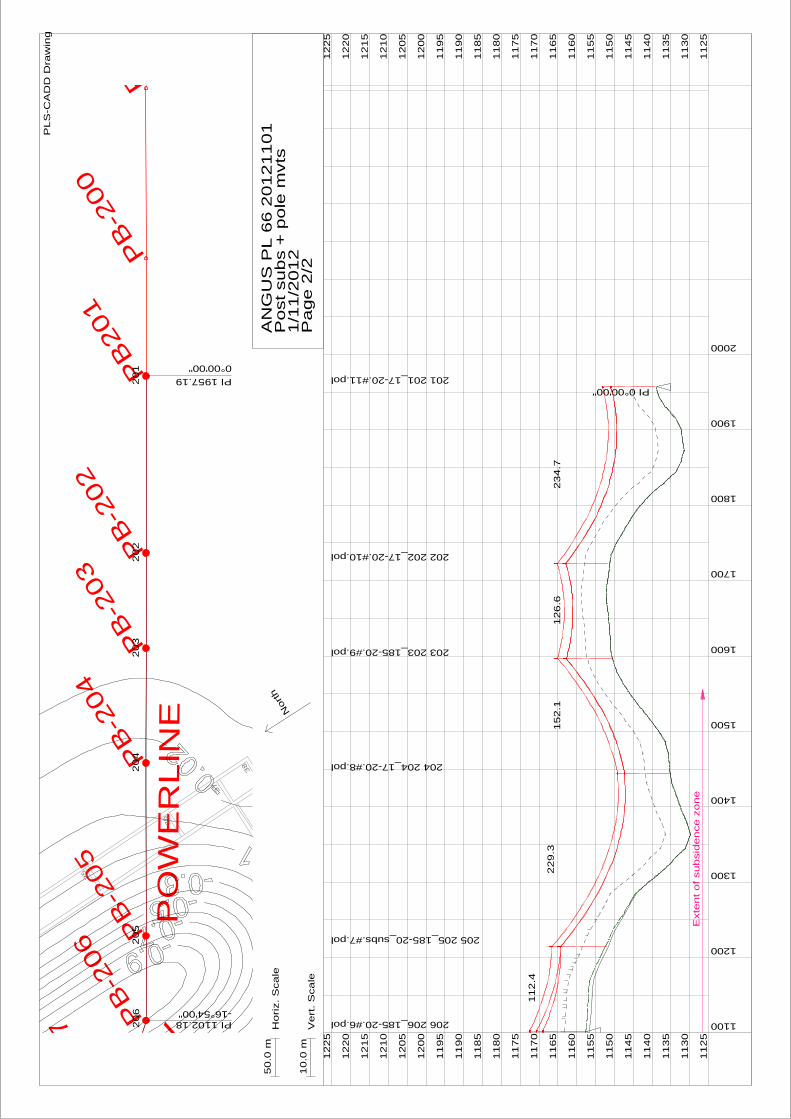

Energy Serve
Page 11
PLS-CADD Version 1210x64 40015 PM Thursday 1 November 2012
Energy Serve
Project Name cuserskevin ruggdocumentsenergy servegss environmentalangus placeplsangus pl 66 20121101DON
Line Title Existing
Section Usage Report
Sec Cable From To Percent OK
No Name Str Str Usage NG
-----------------------------------
4 lemon 208 206 498 OK
5 lemon 206 204 489 OK
0 section violations OK
Check Section Summary
designates highest percent of allowable capacity
Sec Cable From To WC Weather Case Condition Allowable Actual Allowable Actual Allowable Actual of OK
No Name Str Str No Description of of Tension Tension Catenary Catenary Allowable or
No No Ultimate Ultimate (N) (N) (m) (m) Capacity NG
-------------------------------------------------------------------------------------------------------------------------------------
4 lemon 208 206 7 Limit 1000 Initial RS 700 348 313862 13423 498 OK
5 lemon 206 204 7 Limit 1000 Initial RS 700 343 308671 13242 489 OK
Page 17 May 2 2013
Appendix E ndash Section Usage Report ndash Post-subsidence
Energy Serve
Page 11
PLS-CADD Version 1210x64 35823 PM Thursday 1 November 2012
Energy Serve
Project Name cuserskevin ruggdocumentsenergy servegss environmentalangus placeplsangus pl 66 20121101DON
Line Title Post subs + pole mvts
Section Usage Report
Sec Cable From To Percent OK
No Name Str Str Usage NG
-----------------------------------
4 lemon 208 206 539 OK
5 lemon 206 204 519 OK
0 section violations OK
Check Section Summary
designates highest percent of allowable capacity
Sec Cable From To WC Weather Case Condition Allowable Actual Allowable Actual Allowable Actual of OK
No Name Str Str No Description of of Tension Tension Catenary Catenary Allowable or
No No Ultimate Ultimate (N) (N) (m) (m) Capacity NG
-------------------------------------------------------------------------------------------------------------------------------------
4 lemon 208 206 7 Limit 1000 Initial FE 700 378 340206 14565 539 OK
5 lemon 206 204 7 Limit 1000 Initial FE 700 363 327374 14052 519 OK
Page 19 May 2 2013
Appendix F ndash Structure Usage Report ndash Existing
Energy Serve
Page 14
PLS-CADD Version 1210x64 40113 PM Thursday 1 November 2012
Energy Serve
Project Name cuserskevin ruggdocumentsenergy servegss environmentalangus placeplsangus pl 66 20121101DON
Line Title Existing
Structure Locations and Usage Report
Structure Structure Station Line --Constraints--- Structure Insulator Minimum Pole OK
Number Name Angle Prohib Req Extra Strength Swing Required Tip or
Zone Pos Cost Usage Usage Vertical Deflection NG
Load Usage
(m) (deg) () () (Uplift) ()
---------------------------------------------------------------------------------------------------------
208 208_185-204pol 73777 000 0 737 00 OK OK
207 207_17-205pol 97945 000 0 531 320 OK OK
206 206_185-206pol 110218 -1690 Y 0 698 00 OK OK
205 205_185-207pol 121453 000 0 432 495 OK OK
204 204_17-208pol 144382 000 0 694 00 OK OK
0 structure violations 0 structure warnings OK
Energy Serve
Page 24
Multiple Structure Suspension Insulator Swing Angles and V-String Load Angles
Str Set Phase Swing Weather Wire Min Max Min Max of OK
Cond Case Condition Allowed Allowed Calc Calc Allowed
Description (deg) (deg) (deg) (deg) Swing
-----------------------------------------------------------------------------------------------------
207 3 1 1 Hot 85 Creep RS -900 900 -40 -40 45 OK
2 1 Hot 85 Creep RS -900 900 27 27 30 OK
3 1 Hot 85 Creep RS -900 900 -26 -26 29 OK
1 2 Swing 210 Initial RS -900 900 -166 57 184 OK
2 2 Swing 210 Initial RS -900 900 -78 153 170 OK
3 2 Swing 210 Initial RS -900 900 -142 72 158 OK
1 3 Swing 500 Initial RS -900 900 -288 188 320 OK
2 3 Swing 500 Initial RS -900 900 -212 280 311 OK
3 3 Swing 500 Initial RS -900 900 -261 197 290 OK
1 4 Cold 0 Initial RS -900 900 -59 -59 65 OK
2 4 Cold 0 Initial RS -900 900 40 40 45 OK
3 4 Cold 0 Initial RS -900 900 -37 -37 42 OK
205 1 1 Hot 85 Creep RS -900 900 -64 -64 71 OK
2 1 Hot 85 Creep RS -900 900 45 45 50 OK
3 1 Hot 85 Creep RS -900 900 -41 -41 46 OK
1 2 Swing 210 Initial RS -900 900 -276 81 307 OK
2 2 Swing 210 Initial RS -900 900 -123 263 293 OK
3 2 Swing 210 Initial RS -900 900 -231 107 257 OK
1 3 Swing 500 Initial RS -900 900 -444 295 493 OK
2 3 Swing 500 Initial RS -900 900 -343 446 495 OK
3 3 Swing 500 Initial RS -900 900 -400 301 444 OK
1 4 Cold 0 Initial RS -900 900 -115 -115 128 OK
2 4 Cold 0 Initial RS -900 900 85 85 94 OK
3 4 Cold 0 Initial RS -900 900 -72 -72 80 OK
Energy Serve
Page 34
Multiple Structure Minimum Vertical Load (Uplift) Summary
Str Set Phase Swing Weather Wire Min Vert Vert Vert OK
Cond Case Condition Req Load Load Load
Description Vert Wind Wind Margin
Load From From
Left Right
(N) (N) (N) (N)
-----------------------------------------------------------------------------------
207 3 1 1 Hot 85 Creep RS 0 2967 2967 2967 OK
2 1 Hot 85 Creep RS 0 2901 2901 2901 OK
3 1 Hot 85 Creep RS 0 3069 3069 3069 OK
1 2 Swing 210 Initial RS 0 3982 3982 3982 OK
2 2 Swing 210 Initial RS 0 3858 3858 3858 OK
3 2 Swing 210 Initial RS 0 4172 4172 4172 OK
1 3 Swing 500 Initial RS 0 4246 4246 4246 OK
2 3 Swing 500 Initial RS 0 4107 4107 4107 OK
3 3 Swing 500 Initial RS 0 4459 4459 4459 OK
1 4 Cold 0 Initial RS 0 4175 4175 4175 OK
2 4 Cold 0 Initial RS 0 4041 4041 4041 OK
3 4 Cold 0 Initial RS 0 4382 4382 4382 OK
205 1 1 Hot 85 Creep RS 0 1936 1936 1936 OK
2 1 Hot 85 Creep RS 0 1853 1853 1853 OK
3 1 Hot 85 Creep RS 0 2033 2033 2033 OK
1 2 Swing 210 Initial RS 0 2173 2173 2173 OK
2 2 Swing 210 Initial RS 0 2016 2016 2016 OK
3 2 Swing 210 Initial RS 0 2359 2359 2359 OK
1 3 Swing 500 Initial RS 0 2231 2231 2231 OK
2 3 Swing 500 Initial RS 0 2056 2056 2056 OK
3 3 Swing 500 Initial RS 0 2438 2438 2438 OK
1 4 Cold 0 Initial RS 0 2220 2220 2220 OK
2 4 Cold 0 Initial RS 0 2049 2049 2049 OK
3 4 Cold 0 Initial RS 0 2424 2424 2424 OK
Energy Serve
Page 44
Page 24 May 2 2013
Appendix G ndash Structure Usage Report ndash Post-subsidence
Energy Serve
Page 14
PLS-CADD Version 1210x64 40449 PM Thursday 1 November 2012
Energy Serve
Project Name cuserskevin ruggdocumentsenergy servegss environmentalangus placeplsangus pl 66 20121101DON
Line Title Post subs + pole mvts
Structure Locations and Usage Report
Structure Structure Station Line --Constraints--- Structure Insulator Minimum Pole OK
Number Name Angle Prohib Req Extra Strength Swing Required Tip or
Zone Pos Cost Usage Usage Vertical Deflection NG
Load Usage
(m) (deg) () () (Uplift) ()
--------------------------------------------------------------------------------------------------------------
208 208_185-204pol 73777 000 0 747 00 OK OK
207 207_17-20_subs5pol 97945 000 0 606 288 OK OK
206 206_185-20_subs6pol 110218 -1690 Y 0 728 00 OK OK
205 205_185-20_subs7pol 121453 000 0 447 449 OK OK
204 204_17-208pol 144382 000 0 714 00 OK OK
0 structure violations 0 structure warnings OK
Energy Serve
Page 24
Multiple Structure Suspension Insulator Swing Angles and V-String Load Angles
Str Set Phase Swing Weather Wire Min Max Min Max of OK
Cond Case Condition Allowed Allowed Calc Calc Allowed
Description (deg) (deg) (deg) (deg) Swing
-----------------------------------------------------------------------------------------------------
207 3 1 1 Hot 85 Creep FE -900 900 -37 -37 41 OK
2 1 Hot 85 Creep FE -900 900 29 29 32 OK
3 1 Hot 85 Creep FE -900 900 -23 -23 26 OK
1 2 Swing 210 Initial FE -900 900 -149 49 165 OK
2 2 Swing 210 Initial FE -900 900 -62 141 157 OK
3 2 Swing 210 Initial FE -900 900 -126 64 140 OK
1 3 Swing 500 Initial FE -900 900 -259 165 288 OK
2 3 Swing 500 Initial FE -900 900 -181 255 284 OK
3 3 Swing 500 Initial FE -900 900 -234 174 260 OK
1 4 Cold 0 Initial FE -900 900 -53 -53 59 OK
2 4 Cold 0 Initial FE -900 900 42 42 47 OK
3 4 Cold 0 Initial FE -900 900 -33 -33 37 OK
205 1 1 Hot 85 Creep FE -900 900 -65 -65 72 OK
2 1 Hot 85 Creep FE -900 900 34 34 38 OK
3 1 Hot 85 Creep FE -900 900 -42 -42 47 OK
1 2 Swing 210 Initial FE -900 900 -253 52 281 OK
2 2 Swing 210 Initial FE -900 900 -113 224 249 OK
3 2 Swing 210 Initial FE -900 900 -212 84 236 OK
1 3 Swing 500 Initial FE -900 900 -404 237 449 OK
2 3 Swing 500 Initial FE -900 900 -304 393 437 OK
3 3 Swing 500 Initial FE -900 900 -365 257 406 OK
1 4 Cold 0 Initial FE -900 900 -115 -115 127 OK
2 4 Cold 0 Initial FE -900 900 65 65 72 OK
3 4 Cold 0 Initial FE -900 900 -73 -73 81 OK
Energy Serve
Page 34
Multiple Structure Minimum Vertical Load (Uplift) Summary
Str Set Phase Swing Weather Wire Min Vert Vert Vert OK
Cond Case Condition Req Load Load Load
Description Vert Wind Wind Margin
Load From From
Left Right
(N) (N) (N) (N)
-----------------------------------------------------------------------------------
207 3 1 1 Hot 85 Creep RS 0 3066 3066 3066 OK
2 1 Hot 85 Creep RS 0 3006 3006 3006 OK
3 1 Hot 85 Creep RS 0 3179 3179 3179 OK
1 2 Swing 210 Initial RS 0 4193 4186 4186 OK
2 2 Swing 210 Initial RS 0 4087 4086 4086 OK
3 2 Swing 210 Initial RS 0 4426 4419 4419 OK
1 3 Swing 500 Initial RS 0 4488 4474 4474 OK
2 3 Swing 500 Initial RS 0 4364 4361 4361 OK
3 3 Swing 500 Initial RS 0 4742 4726 4726 OK
1 4 Cold 0 Initial RS 0 4388 4388 4388 OK
2 4 Cold 0 Initial RS 0 4275 4275 4275 OK
3 4 Cold 0 Initial RS 0 4640 4640 4640 OK
205 1 1 Hot 85 Creep RS 0 1968 1968 1968 OK
2 1 Hot 85 Creep RS 0 1887 1887 1887 OK
3 1 Hot 85 Creep RS 0 2061 2061 2061 OK
1 2 Swing 210 Initial RS 0 2224 2245 2224 OK
2 2 Swing 210 Initial RS 0 2074 2059 2059 OK
3 2 Swing 210 Initial RS 0 2401 2412 2401 OK
1 3 Swing 500 Initial RS 0 2315 2353 2315 OK
2 3 Swing 500 Initial RS 0 2170 2142 2142 OK
3 3 Swing 500 Initial RS 0 2518 2539 2518 OK
1 4 Cold 0 Initial RS 0 2274 2274 2274 OK
2 4 Cold 0 Initial RS 0 2087 2087 2087 OK
3 4 Cold 0 Initial RS 0 2461 2461 2461 OK
Energy Serve
Page 44
Page 29 May 2 2013
Appendix H ndash Endeavour Energy ndash David Mate ndash Email 25 March 2013
From David MateTo Kevin RuggSubject RE Centennial Coal - Angus Place - Subsidence Impact of Endeavour Energy 66kV Feeder 811Date Monday 25 March 2013 120800 PMAttachments image001png
Hi Kevin Based on the information in the report I have no issues in relation to the subsidence at AngusPlace
RegardsDavid David MateOverhead amp Underground Mains Manager ( 02 9853 6010Egrave 0413 227 4997 02 9853 6021 davidmateendeavourenergycomau 51 Huntingwood Drive Huntingwood NSW 2148 wwwendeavourenergycomau
From Kevin Rugg [mailtokevinenergyservecomau] Sent Monday 25 March 2013 1145 AMTo David MateSubject RE Centennial Coal - Angus Place - Subsidence Impact of Endeavour Energy 66kV Feeder811 Thanks David Thatrsquos all good but I am trying to find someone within Endeavour who will give us the all clear onthe subsidence impact assessment Cheers Kevin Rugg kevinenergyservecomau Energy ServeJemtom Pty Ltd(ABN 36 078 771 650)Ph (02) 6885 3224Fax (02) 6885 3210Mob 0427 853 224 This message is intended for the addressee named and may contain confidential information If you are not the intended

Energy Serve
Page 11
PLS-CADD Version 1210x64 35823 PM Thursday 1 November 2012
Energy Serve
Project Name cuserskevin ruggdocumentsenergy servegss environmentalangus placeplsangus pl 66 20121101DON
Line Title Post subs + pole mvts
Section Usage Report
Sec Cable From To Percent OK
No Name Str Str Usage NG
-----------------------------------
4 lemon 208 206 539 OK
5 lemon 206 204 519 OK
0 section violations OK
Check Section Summary
designates highest percent of allowable capacity
Sec Cable From To WC Weather Case Condition Allowable Actual Allowable Actual Allowable Actual of OK
No Name Str Str No Description of of Tension Tension Catenary Catenary Allowable or
No No Ultimate Ultimate (N) (N) (m) (m) Capacity NG
-------------------------------------------------------------------------------------------------------------------------------------
4 lemon 208 206 7 Limit 1000 Initial FE 700 378 340206 14565 539 OK
5 lemon 206 204 7 Limit 1000 Initial FE 700 363 327374 14052 519 OK
Page 19 May 2 2013
Appendix F ndash Structure Usage Report ndash Existing
Energy Serve
Page 14
PLS-CADD Version 1210x64 40113 PM Thursday 1 November 2012
Energy Serve
Project Name cuserskevin ruggdocumentsenergy servegss environmentalangus placeplsangus pl 66 20121101DON
Line Title Existing
Structure Locations and Usage Report
Structure Structure Station Line --Constraints--- Structure Insulator Minimum Pole OK
Number Name Angle Prohib Req Extra Strength Swing Required Tip or
Zone Pos Cost Usage Usage Vertical Deflection NG
Load Usage
(m) (deg) () () (Uplift) ()
---------------------------------------------------------------------------------------------------------
208 208_185-204pol 73777 000 0 737 00 OK OK
207 207_17-205pol 97945 000 0 531 320 OK OK
206 206_185-206pol 110218 -1690 Y 0 698 00 OK OK
205 205_185-207pol 121453 000 0 432 495 OK OK
204 204_17-208pol 144382 000 0 694 00 OK OK
0 structure violations 0 structure warnings OK
Energy Serve
Page 24
Multiple Structure Suspension Insulator Swing Angles and V-String Load Angles
Str Set Phase Swing Weather Wire Min Max Min Max of OK
Cond Case Condition Allowed Allowed Calc Calc Allowed
Description (deg) (deg) (deg) (deg) Swing
-----------------------------------------------------------------------------------------------------
207 3 1 1 Hot 85 Creep RS -900 900 -40 -40 45 OK
2 1 Hot 85 Creep RS -900 900 27 27 30 OK
3 1 Hot 85 Creep RS -900 900 -26 -26 29 OK
1 2 Swing 210 Initial RS -900 900 -166 57 184 OK
2 2 Swing 210 Initial RS -900 900 -78 153 170 OK
3 2 Swing 210 Initial RS -900 900 -142 72 158 OK
1 3 Swing 500 Initial RS -900 900 -288 188 320 OK
2 3 Swing 500 Initial RS -900 900 -212 280 311 OK
3 3 Swing 500 Initial RS -900 900 -261 197 290 OK
1 4 Cold 0 Initial RS -900 900 -59 -59 65 OK
2 4 Cold 0 Initial RS -900 900 40 40 45 OK
3 4 Cold 0 Initial RS -900 900 -37 -37 42 OK
205 1 1 Hot 85 Creep RS -900 900 -64 -64 71 OK
2 1 Hot 85 Creep RS -900 900 45 45 50 OK
3 1 Hot 85 Creep RS -900 900 -41 -41 46 OK
1 2 Swing 210 Initial RS -900 900 -276 81 307 OK
2 2 Swing 210 Initial RS -900 900 -123 263 293 OK
3 2 Swing 210 Initial RS -900 900 -231 107 257 OK
1 3 Swing 500 Initial RS -900 900 -444 295 493 OK
2 3 Swing 500 Initial RS -900 900 -343 446 495 OK
3 3 Swing 500 Initial RS -900 900 -400 301 444 OK
1 4 Cold 0 Initial RS -900 900 -115 -115 128 OK
2 4 Cold 0 Initial RS -900 900 85 85 94 OK
3 4 Cold 0 Initial RS -900 900 -72 -72 80 OK
Energy Serve
Page 34
Multiple Structure Minimum Vertical Load (Uplift) Summary
Str Set Phase Swing Weather Wire Min Vert Vert Vert OK
Cond Case Condition Req Load Load Load
Description Vert Wind Wind Margin
Load From From
Left Right
(N) (N) (N) (N)
-----------------------------------------------------------------------------------
207 3 1 1 Hot 85 Creep RS 0 2967 2967 2967 OK
2 1 Hot 85 Creep RS 0 2901 2901 2901 OK
3 1 Hot 85 Creep RS 0 3069 3069 3069 OK
1 2 Swing 210 Initial RS 0 3982 3982 3982 OK
2 2 Swing 210 Initial RS 0 3858 3858 3858 OK
3 2 Swing 210 Initial RS 0 4172 4172 4172 OK
1 3 Swing 500 Initial RS 0 4246 4246 4246 OK
2 3 Swing 500 Initial RS 0 4107 4107 4107 OK
3 3 Swing 500 Initial RS 0 4459 4459 4459 OK
1 4 Cold 0 Initial RS 0 4175 4175 4175 OK
2 4 Cold 0 Initial RS 0 4041 4041 4041 OK
3 4 Cold 0 Initial RS 0 4382 4382 4382 OK
205 1 1 Hot 85 Creep RS 0 1936 1936 1936 OK
2 1 Hot 85 Creep RS 0 1853 1853 1853 OK
3 1 Hot 85 Creep RS 0 2033 2033 2033 OK
1 2 Swing 210 Initial RS 0 2173 2173 2173 OK
2 2 Swing 210 Initial RS 0 2016 2016 2016 OK
3 2 Swing 210 Initial RS 0 2359 2359 2359 OK
1 3 Swing 500 Initial RS 0 2231 2231 2231 OK
2 3 Swing 500 Initial RS 0 2056 2056 2056 OK
3 3 Swing 500 Initial RS 0 2438 2438 2438 OK
1 4 Cold 0 Initial RS 0 2220 2220 2220 OK
2 4 Cold 0 Initial RS 0 2049 2049 2049 OK
3 4 Cold 0 Initial RS 0 2424 2424 2424 OK
Energy Serve
Page 44
Page 24 May 2 2013
Appendix G ndash Structure Usage Report ndash Post-subsidence
Energy Serve
Page 14
PLS-CADD Version 1210x64 40449 PM Thursday 1 November 2012
Energy Serve
Project Name cuserskevin ruggdocumentsenergy servegss environmentalangus placeplsangus pl 66 20121101DON
Line Title Post subs + pole mvts
Structure Locations and Usage Report
Structure Structure Station Line --Constraints--- Structure Insulator Minimum Pole OK
Number Name Angle Prohib Req Extra Strength Swing Required Tip or
Zone Pos Cost Usage Usage Vertical Deflection NG
Load Usage
(m) (deg) () () (Uplift) ()
--------------------------------------------------------------------------------------------------------------
208 208_185-204pol 73777 000 0 747 00 OK OK
207 207_17-20_subs5pol 97945 000 0 606 288 OK OK
206 206_185-20_subs6pol 110218 -1690 Y 0 728 00 OK OK
205 205_185-20_subs7pol 121453 000 0 447 449 OK OK
204 204_17-208pol 144382 000 0 714 00 OK OK
0 structure violations 0 structure warnings OK
Energy Serve
Page 24
Multiple Structure Suspension Insulator Swing Angles and V-String Load Angles
Str Set Phase Swing Weather Wire Min Max Min Max of OK
Cond Case Condition Allowed Allowed Calc Calc Allowed
Description (deg) (deg) (deg) (deg) Swing
-----------------------------------------------------------------------------------------------------
207 3 1 1 Hot 85 Creep FE -900 900 -37 -37 41 OK
2 1 Hot 85 Creep FE -900 900 29 29 32 OK
3 1 Hot 85 Creep FE -900 900 -23 -23 26 OK
1 2 Swing 210 Initial FE -900 900 -149 49 165 OK
2 2 Swing 210 Initial FE -900 900 -62 141 157 OK
3 2 Swing 210 Initial FE -900 900 -126 64 140 OK
1 3 Swing 500 Initial FE -900 900 -259 165 288 OK
2 3 Swing 500 Initial FE -900 900 -181 255 284 OK
3 3 Swing 500 Initial FE -900 900 -234 174 260 OK
1 4 Cold 0 Initial FE -900 900 -53 -53 59 OK
2 4 Cold 0 Initial FE -900 900 42 42 47 OK
3 4 Cold 0 Initial FE -900 900 -33 -33 37 OK
205 1 1 Hot 85 Creep FE -900 900 -65 -65 72 OK
2 1 Hot 85 Creep FE -900 900 34 34 38 OK
3 1 Hot 85 Creep FE -900 900 -42 -42 47 OK
1 2 Swing 210 Initial FE -900 900 -253 52 281 OK
2 2 Swing 210 Initial FE -900 900 -113 224 249 OK
3 2 Swing 210 Initial FE -900 900 -212 84 236 OK
1 3 Swing 500 Initial FE -900 900 -404 237 449 OK
2 3 Swing 500 Initial FE -900 900 -304 393 437 OK
3 3 Swing 500 Initial FE -900 900 -365 257 406 OK
1 4 Cold 0 Initial FE -900 900 -115 -115 127 OK
2 4 Cold 0 Initial FE -900 900 65 65 72 OK
3 4 Cold 0 Initial FE -900 900 -73 -73 81 OK
Energy Serve
Page 34
Multiple Structure Minimum Vertical Load (Uplift) Summary
Str Set Phase Swing Weather Wire Min Vert Vert Vert OK
Cond Case Condition Req Load Load Load
Description Vert Wind Wind Margin
Load From From
Left Right
(N) (N) (N) (N)
-----------------------------------------------------------------------------------
207 3 1 1 Hot 85 Creep RS 0 3066 3066 3066 OK
2 1 Hot 85 Creep RS 0 3006 3006 3006 OK
3 1 Hot 85 Creep RS 0 3179 3179 3179 OK
1 2 Swing 210 Initial RS 0 4193 4186 4186 OK
2 2 Swing 210 Initial RS 0 4087 4086 4086 OK
3 2 Swing 210 Initial RS 0 4426 4419 4419 OK
1 3 Swing 500 Initial RS 0 4488 4474 4474 OK
2 3 Swing 500 Initial RS 0 4364 4361 4361 OK
3 3 Swing 500 Initial RS 0 4742 4726 4726 OK
1 4 Cold 0 Initial RS 0 4388 4388 4388 OK
2 4 Cold 0 Initial RS 0 4275 4275 4275 OK
3 4 Cold 0 Initial RS 0 4640 4640 4640 OK
205 1 1 Hot 85 Creep RS 0 1968 1968 1968 OK
2 1 Hot 85 Creep RS 0 1887 1887 1887 OK
3 1 Hot 85 Creep RS 0 2061 2061 2061 OK
1 2 Swing 210 Initial RS 0 2224 2245 2224 OK
2 2 Swing 210 Initial RS 0 2074 2059 2059 OK
3 2 Swing 210 Initial RS 0 2401 2412 2401 OK
1 3 Swing 500 Initial RS 0 2315 2353 2315 OK
2 3 Swing 500 Initial RS 0 2170 2142 2142 OK
3 3 Swing 500 Initial RS 0 2518 2539 2518 OK
1 4 Cold 0 Initial RS 0 2274 2274 2274 OK
2 4 Cold 0 Initial RS 0 2087 2087 2087 OK
3 4 Cold 0 Initial RS 0 2461 2461 2461 OK
Energy Serve
Page 44
Page 29 May 2 2013
Appendix H ndash Endeavour Energy ndash David Mate ndash Email 25 March 2013
From David MateTo Kevin RuggSubject RE Centennial Coal - Angus Place - Subsidence Impact of Endeavour Energy 66kV Feeder 811Date Monday 25 March 2013 120800 PMAttachments image001png
Hi Kevin Based on the information in the report I have no issues in relation to the subsidence at AngusPlace
RegardsDavid David MateOverhead amp Underground Mains Manager ( 02 9853 6010Egrave 0413 227 4997 02 9853 6021 davidmateendeavourenergycomau 51 Huntingwood Drive Huntingwood NSW 2148 wwwendeavourenergycomau
From Kevin Rugg [mailtokevinenergyservecomau] Sent Monday 25 March 2013 1145 AMTo David MateSubject RE Centennial Coal - Angus Place - Subsidence Impact of Endeavour Energy 66kV Feeder811 Thanks David Thatrsquos all good but I am trying to find someone within Endeavour who will give us the all clear onthe subsidence impact assessment Cheers Kevin Rugg kevinenergyservecomau Energy ServeJemtom Pty Ltd(ABN 36 078 771 650)Ph (02) 6885 3224Fax (02) 6885 3210Mob 0427 853 224 This message is intended for the addressee named and may contain confidential information If you are not the intended
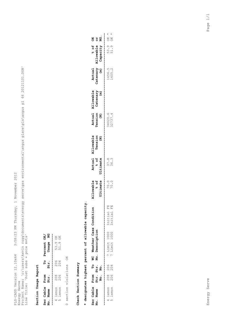

Energy Serve
Page 14
PLS-CADD Version 1210x64 40113 PM Thursday 1 November 2012
Energy Serve
Project Name cuserskevin ruggdocumentsenergy servegss environmentalangus placeplsangus pl 66 20121101DON
Line Title Existing
Structure Locations and Usage Report
Structure Structure Station Line --Constraints--- Structure Insulator Minimum Pole OK
Number Name Angle Prohib Req Extra Strength Swing Required Tip or
Zone Pos Cost Usage Usage Vertical Deflection NG
Load Usage
(m) (deg) () () (Uplift) ()
---------------------------------------------------------------------------------------------------------
208 208_185-204pol 73777 000 0 737 00 OK OK
207 207_17-205pol 97945 000 0 531 320 OK OK
206 206_185-206pol 110218 -1690 Y 0 698 00 OK OK
205 205_185-207pol 121453 000 0 432 495 OK OK
204 204_17-208pol 144382 000 0 694 00 OK OK
0 structure violations 0 structure warnings OK
Energy Serve
Page 24
Multiple Structure Suspension Insulator Swing Angles and V-String Load Angles
Str Set Phase Swing Weather Wire Min Max Min Max of OK
Cond Case Condition Allowed Allowed Calc Calc Allowed
Description (deg) (deg) (deg) (deg) Swing
-----------------------------------------------------------------------------------------------------
207 3 1 1 Hot 85 Creep RS -900 900 -40 -40 45 OK
2 1 Hot 85 Creep RS -900 900 27 27 30 OK
3 1 Hot 85 Creep RS -900 900 -26 -26 29 OK
1 2 Swing 210 Initial RS -900 900 -166 57 184 OK
2 2 Swing 210 Initial RS -900 900 -78 153 170 OK
3 2 Swing 210 Initial RS -900 900 -142 72 158 OK
1 3 Swing 500 Initial RS -900 900 -288 188 320 OK
2 3 Swing 500 Initial RS -900 900 -212 280 311 OK
3 3 Swing 500 Initial RS -900 900 -261 197 290 OK
1 4 Cold 0 Initial RS -900 900 -59 -59 65 OK
2 4 Cold 0 Initial RS -900 900 40 40 45 OK
3 4 Cold 0 Initial RS -900 900 -37 -37 42 OK
205 1 1 Hot 85 Creep RS -900 900 -64 -64 71 OK
2 1 Hot 85 Creep RS -900 900 45 45 50 OK
3 1 Hot 85 Creep RS -900 900 -41 -41 46 OK
1 2 Swing 210 Initial RS -900 900 -276 81 307 OK
2 2 Swing 210 Initial RS -900 900 -123 263 293 OK
3 2 Swing 210 Initial RS -900 900 -231 107 257 OK
1 3 Swing 500 Initial RS -900 900 -444 295 493 OK
2 3 Swing 500 Initial RS -900 900 -343 446 495 OK
3 3 Swing 500 Initial RS -900 900 -400 301 444 OK
1 4 Cold 0 Initial RS -900 900 -115 -115 128 OK
2 4 Cold 0 Initial RS -900 900 85 85 94 OK
3 4 Cold 0 Initial RS -900 900 -72 -72 80 OK
Energy Serve
Page 34
Multiple Structure Minimum Vertical Load (Uplift) Summary
Str Set Phase Swing Weather Wire Min Vert Vert Vert OK
Cond Case Condition Req Load Load Load
Description Vert Wind Wind Margin
Load From From
Left Right
(N) (N) (N) (N)
-----------------------------------------------------------------------------------
207 3 1 1 Hot 85 Creep RS 0 2967 2967 2967 OK
2 1 Hot 85 Creep RS 0 2901 2901 2901 OK
3 1 Hot 85 Creep RS 0 3069 3069 3069 OK
1 2 Swing 210 Initial RS 0 3982 3982 3982 OK
2 2 Swing 210 Initial RS 0 3858 3858 3858 OK
3 2 Swing 210 Initial RS 0 4172 4172 4172 OK
1 3 Swing 500 Initial RS 0 4246 4246 4246 OK
2 3 Swing 500 Initial RS 0 4107 4107 4107 OK
3 3 Swing 500 Initial RS 0 4459 4459 4459 OK
1 4 Cold 0 Initial RS 0 4175 4175 4175 OK
2 4 Cold 0 Initial RS 0 4041 4041 4041 OK
3 4 Cold 0 Initial RS 0 4382 4382 4382 OK
205 1 1 Hot 85 Creep RS 0 1936 1936 1936 OK
2 1 Hot 85 Creep RS 0 1853 1853 1853 OK
3 1 Hot 85 Creep RS 0 2033 2033 2033 OK
1 2 Swing 210 Initial RS 0 2173 2173 2173 OK
2 2 Swing 210 Initial RS 0 2016 2016 2016 OK
3 2 Swing 210 Initial RS 0 2359 2359 2359 OK
1 3 Swing 500 Initial RS 0 2231 2231 2231 OK
2 3 Swing 500 Initial RS 0 2056 2056 2056 OK
3 3 Swing 500 Initial RS 0 2438 2438 2438 OK
1 4 Cold 0 Initial RS 0 2220 2220 2220 OK
2 4 Cold 0 Initial RS 0 2049 2049 2049 OK
3 4 Cold 0 Initial RS 0 2424 2424 2424 OK
Energy Serve
Page 44
Page 24 May 2 2013
Appendix G ndash Structure Usage Report ndash Post-subsidence
Energy Serve
Page 14
PLS-CADD Version 1210x64 40449 PM Thursday 1 November 2012
Energy Serve
Project Name cuserskevin ruggdocumentsenergy servegss environmentalangus placeplsangus pl 66 20121101DON
Line Title Post subs + pole mvts
Structure Locations and Usage Report
Structure Structure Station Line --Constraints--- Structure Insulator Minimum Pole OK
Number Name Angle Prohib Req Extra Strength Swing Required Tip or
Zone Pos Cost Usage Usage Vertical Deflection NG
Load Usage
(m) (deg) () () (Uplift) ()
--------------------------------------------------------------------------------------------------------------
208 208_185-204pol 73777 000 0 747 00 OK OK
207 207_17-20_subs5pol 97945 000 0 606 288 OK OK
206 206_185-20_subs6pol 110218 -1690 Y 0 728 00 OK OK
205 205_185-20_subs7pol 121453 000 0 447 449 OK OK
204 204_17-208pol 144382 000 0 714 00 OK OK
0 structure violations 0 structure warnings OK
Energy Serve
Page 24
Multiple Structure Suspension Insulator Swing Angles and V-String Load Angles
Str Set Phase Swing Weather Wire Min Max Min Max of OK
Cond Case Condition Allowed Allowed Calc Calc Allowed
Description (deg) (deg) (deg) (deg) Swing
-----------------------------------------------------------------------------------------------------
207 3 1 1 Hot 85 Creep FE -900 900 -37 -37 41 OK
2 1 Hot 85 Creep FE -900 900 29 29 32 OK
3 1 Hot 85 Creep FE -900 900 -23 -23 26 OK
1 2 Swing 210 Initial FE -900 900 -149 49 165 OK
2 2 Swing 210 Initial FE -900 900 -62 141 157 OK
3 2 Swing 210 Initial FE -900 900 -126 64 140 OK
1 3 Swing 500 Initial FE -900 900 -259 165 288 OK
2 3 Swing 500 Initial FE -900 900 -181 255 284 OK
3 3 Swing 500 Initial FE -900 900 -234 174 260 OK
1 4 Cold 0 Initial FE -900 900 -53 -53 59 OK
2 4 Cold 0 Initial FE -900 900 42 42 47 OK
3 4 Cold 0 Initial FE -900 900 -33 -33 37 OK
205 1 1 Hot 85 Creep FE -900 900 -65 -65 72 OK
2 1 Hot 85 Creep FE -900 900 34 34 38 OK
3 1 Hot 85 Creep FE -900 900 -42 -42 47 OK
1 2 Swing 210 Initial FE -900 900 -253 52 281 OK
2 2 Swing 210 Initial FE -900 900 -113 224 249 OK
3 2 Swing 210 Initial FE -900 900 -212 84 236 OK
1 3 Swing 500 Initial FE -900 900 -404 237 449 OK
2 3 Swing 500 Initial FE -900 900 -304 393 437 OK
3 3 Swing 500 Initial FE -900 900 -365 257 406 OK
1 4 Cold 0 Initial FE -900 900 -115 -115 127 OK
2 4 Cold 0 Initial FE -900 900 65 65 72 OK
3 4 Cold 0 Initial FE -900 900 -73 -73 81 OK
Energy Serve
Page 34
Multiple Structure Minimum Vertical Load (Uplift) Summary
Str Set Phase Swing Weather Wire Min Vert Vert Vert OK
Cond Case Condition Req Load Load Load
Description Vert Wind Wind Margin
Load From From
Left Right
(N) (N) (N) (N)
-----------------------------------------------------------------------------------
207 3 1 1 Hot 85 Creep RS 0 3066 3066 3066 OK
2 1 Hot 85 Creep RS 0 3006 3006 3006 OK
3 1 Hot 85 Creep RS 0 3179 3179 3179 OK
1 2 Swing 210 Initial RS 0 4193 4186 4186 OK
2 2 Swing 210 Initial RS 0 4087 4086 4086 OK
3 2 Swing 210 Initial RS 0 4426 4419 4419 OK
1 3 Swing 500 Initial RS 0 4488 4474 4474 OK
2 3 Swing 500 Initial RS 0 4364 4361 4361 OK
3 3 Swing 500 Initial RS 0 4742 4726 4726 OK
1 4 Cold 0 Initial RS 0 4388 4388 4388 OK
2 4 Cold 0 Initial RS 0 4275 4275 4275 OK
3 4 Cold 0 Initial RS 0 4640 4640 4640 OK
205 1 1 Hot 85 Creep RS 0 1968 1968 1968 OK
2 1 Hot 85 Creep RS 0 1887 1887 1887 OK
3 1 Hot 85 Creep RS 0 2061 2061 2061 OK
1 2 Swing 210 Initial RS 0 2224 2245 2224 OK
2 2 Swing 210 Initial RS 0 2074 2059 2059 OK
3 2 Swing 210 Initial RS 0 2401 2412 2401 OK
1 3 Swing 500 Initial RS 0 2315 2353 2315 OK
2 3 Swing 500 Initial RS 0 2170 2142 2142 OK
3 3 Swing 500 Initial RS 0 2518 2539 2518 OK
1 4 Cold 0 Initial RS 0 2274 2274 2274 OK
2 4 Cold 0 Initial RS 0 2087 2087 2087 OK
3 4 Cold 0 Initial RS 0 2461 2461 2461 OK
Energy Serve
Page 44
Page 29 May 2 2013
Appendix H ndash Endeavour Energy ndash David Mate ndash Email 25 March 2013
From David MateTo Kevin RuggSubject RE Centennial Coal - Angus Place - Subsidence Impact of Endeavour Energy 66kV Feeder 811Date Monday 25 March 2013 120800 PMAttachments image001png
Hi Kevin Based on the information in the report I have no issues in relation to the subsidence at AngusPlace
RegardsDavid David MateOverhead amp Underground Mains Manager ( 02 9853 6010Egrave 0413 227 4997 02 9853 6021 davidmateendeavourenergycomau 51 Huntingwood Drive Huntingwood NSW 2148 wwwendeavourenergycomau
From Kevin Rugg [mailtokevinenergyservecomau] Sent Monday 25 March 2013 1145 AMTo David MateSubject RE Centennial Coal - Angus Place - Subsidence Impact of Endeavour Energy 66kV Feeder811 Thanks David Thatrsquos all good but I am trying to find someone within Endeavour who will give us the all clear onthe subsidence impact assessment Cheers Kevin Rugg kevinenergyservecomau Energy ServeJemtom Pty Ltd(ABN 36 078 771 650)Ph (02) 6885 3224Fax (02) 6885 3210Mob 0427 853 224 This message is intended for the addressee named and may contain confidential information If you are not the intended

Energy Serve
Page 24
Multiple Structure Suspension Insulator Swing Angles and V-String Load Angles
Str Set Phase Swing Weather Wire Min Max Min Max of OK
Cond Case Condition Allowed Allowed Calc Calc Allowed
Description (deg) (deg) (deg) (deg) Swing
-----------------------------------------------------------------------------------------------------
207 3 1 1 Hot 85 Creep RS -900 900 -40 -40 45 OK
2 1 Hot 85 Creep RS -900 900 27 27 30 OK
3 1 Hot 85 Creep RS -900 900 -26 -26 29 OK
1 2 Swing 210 Initial RS -900 900 -166 57 184 OK
2 2 Swing 210 Initial RS -900 900 -78 153 170 OK
3 2 Swing 210 Initial RS -900 900 -142 72 158 OK
1 3 Swing 500 Initial RS -900 900 -288 188 320 OK
2 3 Swing 500 Initial RS -900 900 -212 280 311 OK
3 3 Swing 500 Initial RS -900 900 -261 197 290 OK
1 4 Cold 0 Initial RS -900 900 -59 -59 65 OK
2 4 Cold 0 Initial RS -900 900 40 40 45 OK
3 4 Cold 0 Initial RS -900 900 -37 -37 42 OK
205 1 1 Hot 85 Creep RS -900 900 -64 -64 71 OK
2 1 Hot 85 Creep RS -900 900 45 45 50 OK
3 1 Hot 85 Creep RS -900 900 -41 -41 46 OK
1 2 Swing 210 Initial RS -900 900 -276 81 307 OK
2 2 Swing 210 Initial RS -900 900 -123 263 293 OK
3 2 Swing 210 Initial RS -900 900 -231 107 257 OK
1 3 Swing 500 Initial RS -900 900 -444 295 493 OK
2 3 Swing 500 Initial RS -900 900 -343 446 495 OK
3 3 Swing 500 Initial RS -900 900 -400 301 444 OK
1 4 Cold 0 Initial RS -900 900 -115 -115 128 OK
2 4 Cold 0 Initial RS -900 900 85 85 94 OK
3 4 Cold 0 Initial RS -900 900 -72 -72 80 OK
Energy Serve
Page 34
Multiple Structure Minimum Vertical Load (Uplift) Summary
Str Set Phase Swing Weather Wire Min Vert Vert Vert OK
Cond Case Condition Req Load Load Load
Description Vert Wind Wind Margin
Load From From
Left Right
(N) (N) (N) (N)
-----------------------------------------------------------------------------------
207 3 1 1 Hot 85 Creep RS 0 2967 2967 2967 OK
2 1 Hot 85 Creep RS 0 2901 2901 2901 OK
3 1 Hot 85 Creep RS 0 3069 3069 3069 OK
1 2 Swing 210 Initial RS 0 3982 3982 3982 OK
2 2 Swing 210 Initial RS 0 3858 3858 3858 OK
3 2 Swing 210 Initial RS 0 4172 4172 4172 OK
1 3 Swing 500 Initial RS 0 4246 4246 4246 OK
2 3 Swing 500 Initial RS 0 4107 4107 4107 OK
3 3 Swing 500 Initial RS 0 4459 4459 4459 OK
1 4 Cold 0 Initial RS 0 4175 4175 4175 OK
2 4 Cold 0 Initial RS 0 4041 4041 4041 OK
3 4 Cold 0 Initial RS 0 4382 4382 4382 OK
205 1 1 Hot 85 Creep RS 0 1936 1936 1936 OK
2 1 Hot 85 Creep RS 0 1853 1853 1853 OK
3 1 Hot 85 Creep RS 0 2033 2033 2033 OK
1 2 Swing 210 Initial RS 0 2173 2173 2173 OK
2 2 Swing 210 Initial RS 0 2016 2016 2016 OK
3 2 Swing 210 Initial RS 0 2359 2359 2359 OK
1 3 Swing 500 Initial RS 0 2231 2231 2231 OK
2 3 Swing 500 Initial RS 0 2056 2056 2056 OK
3 3 Swing 500 Initial RS 0 2438 2438 2438 OK
1 4 Cold 0 Initial RS 0 2220 2220 2220 OK
2 4 Cold 0 Initial RS 0 2049 2049 2049 OK
3 4 Cold 0 Initial RS 0 2424 2424 2424 OK
Energy Serve
Page 44
Page 24 May 2 2013
Appendix G ndash Structure Usage Report ndash Post-subsidence
Energy Serve
Page 14
PLS-CADD Version 1210x64 40449 PM Thursday 1 November 2012
Energy Serve
Project Name cuserskevin ruggdocumentsenergy servegss environmentalangus placeplsangus pl 66 20121101DON
Line Title Post subs + pole mvts
Structure Locations and Usage Report
Structure Structure Station Line --Constraints--- Structure Insulator Minimum Pole OK
Number Name Angle Prohib Req Extra Strength Swing Required Tip or
Zone Pos Cost Usage Usage Vertical Deflection NG
Load Usage
(m) (deg) () () (Uplift) ()
--------------------------------------------------------------------------------------------------------------
208 208_185-204pol 73777 000 0 747 00 OK OK
207 207_17-20_subs5pol 97945 000 0 606 288 OK OK
206 206_185-20_subs6pol 110218 -1690 Y 0 728 00 OK OK
205 205_185-20_subs7pol 121453 000 0 447 449 OK OK
204 204_17-208pol 144382 000 0 714 00 OK OK
0 structure violations 0 structure warnings OK
Energy Serve
Page 24
Multiple Structure Suspension Insulator Swing Angles and V-String Load Angles
Str Set Phase Swing Weather Wire Min Max Min Max of OK
Cond Case Condition Allowed Allowed Calc Calc Allowed
Description (deg) (deg) (deg) (deg) Swing
-----------------------------------------------------------------------------------------------------
207 3 1 1 Hot 85 Creep FE -900 900 -37 -37 41 OK
2 1 Hot 85 Creep FE -900 900 29 29 32 OK
3 1 Hot 85 Creep FE -900 900 -23 -23 26 OK
1 2 Swing 210 Initial FE -900 900 -149 49 165 OK
2 2 Swing 210 Initial FE -900 900 -62 141 157 OK
3 2 Swing 210 Initial FE -900 900 -126 64 140 OK
1 3 Swing 500 Initial FE -900 900 -259 165 288 OK
2 3 Swing 500 Initial FE -900 900 -181 255 284 OK
3 3 Swing 500 Initial FE -900 900 -234 174 260 OK
1 4 Cold 0 Initial FE -900 900 -53 -53 59 OK
2 4 Cold 0 Initial FE -900 900 42 42 47 OK
3 4 Cold 0 Initial FE -900 900 -33 -33 37 OK
205 1 1 Hot 85 Creep FE -900 900 -65 -65 72 OK
2 1 Hot 85 Creep FE -900 900 34 34 38 OK
3 1 Hot 85 Creep FE -900 900 -42 -42 47 OK
1 2 Swing 210 Initial FE -900 900 -253 52 281 OK
2 2 Swing 210 Initial FE -900 900 -113 224 249 OK
3 2 Swing 210 Initial FE -900 900 -212 84 236 OK
1 3 Swing 500 Initial FE -900 900 -404 237 449 OK
2 3 Swing 500 Initial FE -900 900 -304 393 437 OK
3 3 Swing 500 Initial FE -900 900 -365 257 406 OK
1 4 Cold 0 Initial FE -900 900 -115 -115 127 OK
2 4 Cold 0 Initial FE -900 900 65 65 72 OK
3 4 Cold 0 Initial FE -900 900 -73 -73 81 OK
Energy Serve
Page 34
Multiple Structure Minimum Vertical Load (Uplift) Summary
Str Set Phase Swing Weather Wire Min Vert Vert Vert OK
Cond Case Condition Req Load Load Load
Description Vert Wind Wind Margin
Load From From
Left Right
(N) (N) (N) (N)
-----------------------------------------------------------------------------------
207 3 1 1 Hot 85 Creep RS 0 3066 3066 3066 OK
2 1 Hot 85 Creep RS 0 3006 3006 3006 OK
3 1 Hot 85 Creep RS 0 3179 3179 3179 OK
1 2 Swing 210 Initial RS 0 4193 4186 4186 OK
2 2 Swing 210 Initial RS 0 4087 4086 4086 OK
3 2 Swing 210 Initial RS 0 4426 4419 4419 OK
1 3 Swing 500 Initial RS 0 4488 4474 4474 OK
2 3 Swing 500 Initial RS 0 4364 4361 4361 OK
3 3 Swing 500 Initial RS 0 4742 4726 4726 OK
1 4 Cold 0 Initial RS 0 4388 4388 4388 OK
2 4 Cold 0 Initial RS 0 4275 4275 4275 OK
3 4 Cold 0 Initial RS 0 4640 4640 4640 OK
205 1 1 Hot 85 Creep RS 0 1968 1968 1968 OK
2 1 Hot 85 Creep RS 0 1887 1887 1887 OK
3 1 Hot 85 Creep RS 0 2061 2061 2061 OK
1 2 Swing 210 Initial RS 0 2224 2245 2224 OK
2 2 Swing 210 Initial RS 0 2074 2059 2059 OK
3 2 Swing 210 Initial RS 0 2401 2412 2401 OK
1 3 Swing 500 Initial RS 0 2315 2353 2315 OK
2 3 Swing 500 Initial RS 0 2170 2142 2142 OK
3 3 Swing 500 Initial RS 0 2518 2539 2518 OK
1 4 Cold 0 Initial RS 0 2274 2274 2274 OK
2 4 Cold 0 Initial RS 0 2087 2087 2087 OK
3 4 Cold 0 Initial RS 0 2461 2461 2461 OK
Energy Serve
Page 44
Page 29 May 2 2013
Appendix H ndash Endeavour Energy ndash David Mate ndash Email 25 March 2013
From David MateTo Kevin RuggSubject RE Centennial Coal - Angus Place - Subsidence Impact of Endeavour Energy 66kV Feeder 811Date Monday 25 March 2013 120800 PMAttachments image001png
Hi Kevin Based on the information in the report I have no issues in relation to the subsidence at AngusPlace
RegardsDavid David MateOverhead amp Underground Mains Manager ( 02 9853 6010Egrave 0413 227 4997 02 9853 6021 davidmateendeavourenergycomau 51 Huntingwood Drive Huntingwood NSW 2148 wwwendeavourenergycomau
From Kevin Rugg [mailtokevinenergyservecomau] Sent Monday 25 March 2013 1145 AMTo David MateSubject RE Centennial Coal - Angus Place - Subsidence Impact of Endeavour Energy 66kV Feeder811 Thanks David Thatrsquos all good but I am trying to find someone within Endeavour who will give us the all clear onthe subsidence impact assessment Cheers Kevin Rugg kevinenergyservecomau Energy ServeJemtom Pty Ltd(ABN 36 078 771 650)Ph (02) 6885 3224Fax (02) 6885 3210Mob 0427 853 224 This message is intended for the addressee named and may contain confidential information If you are not the intended

Energy Serve
Page 34
Multiple Structure Minimum Vertical Load (Uplift) Summary
Str Set Phase Swing Weather Wire Min Vert Vert Vert OK
Cond Case Condition Req Load Load Load
Description Vert Wind Wind Margin
Load From From
Left Right
(N) (N) (N) (N)
-----------------------------------------------------------------------------------
207 3 1 1 Hot 85 Creep RS 0 2967 2967 2967 OK
2 1 Hot 85 Creep RS 0 2901 2901 2901 OK
3 1 Hot 85 Creep RS 0 3069 3069 3069 OK
1 2 Swing 210 Initial RS 0 3982 3982 3982 OK
2 2 Swing 210 Initial RS 0 3858 3858 3858 OK
3 2 Swing 210 Initial RS 0 4172 4172 4172 OK
1 3 Swing 500 Initial RS 0 4246 4246 4246 OK
2 3 Swing 500 Initial RS 0 4107 4107 4107 OK
3 3 Swing 500 Initial RS 0 4459 4459 4459 OK
1 4 Cold 0 Initial RS 0 4175 4175 4175 OK
2 4 Cold 0 Initial RS 0 4041 4041 4041 OK
3 4 Cold 0 Initial RS 0 4382 4382 4382 OK
205 1 1 Hot 85 Creep RS 0 1936 1936 1936 OK
2 1 Hot 85 Creep RS 0 1853 1853 1853 OK
3 1 Hot 85 Creep RS 0 2033 2033 2033 OK
1 2 Swing 210 Initial RS 0 2173 2173 2173 OK
2 2 Swing 210 Initial RS 0 2016 2016 2016 OK
3 2 Swing 210 Initial RS 0 2359 2359 2359 OK
1 3 Swing 500 Initial RS 0 2231 2231 2231 OK
2 3 Swing 500 Initial RS 0 2056 2056 2056 OK
3 3 Swing 500 Initial RS 0 2438 2438 2438 OK
1 4 Cold 0 Initial RS 0 2220 2220 2220 OK
2 4 Cold 0 Initial RS 0 2049 2049 2049 OK
3 4 Cold 0 Initial RS 0 2424 2424 2424 OK
Energy Serve
Page 44
Page 24 May 2 2013
Appendix G ndash Structure Usage Report ndash Post-subsidence
Energy Serve
Page 14
PLS-CADD Version 1210x64 40449 PM Thursday 1 November 2012
Energy Serve
Project Name cuserskevin ruggdocumentsenergy servegss environmentalangus placeplsangus pl 66 20121101DON
Line Title Post subs + pole mvts
Structure Locations and Usage Report
Structure Structure Station Line --Constraints--- Structure Insulator Minimum Pole OK
Number Name Angle Prohib Req Extra Strength Swing Required Tip or
Zone Pos Cost Usage Usage Vertical Deflection NG
Load Usage
(m) (deg) () () (Uplift) ()
--------------------------------------------------------------------------------------------------------------
208 208_185-204pol 73777 000 0 747 00 OK OK
207 207_17-20_subs5pol 97945 000 0 606 288 OK OK
206 206_185-20_subs6pol 110218 -1690 Y 0 728 00 OK OK
205 205_185-20_subs7pol 121453 000 0 447 449 OK OK
204 204_17-208pol 144382 000 0 714 00 OK OK
0 structure violations 0 structure warnings OK
Energy Serve
Page 24
Multiple Structure Suspension Insulator Swing Angles and V-String Load Angles
Str Set Phase Swing Weather Wire Min Max Min Max of OK
Cond Case Condition Allowed Allowed Calc Calc Allowed
Description (deg) (deg) (deg) (deg) Swing
-----------------------------------------------------------------------------------------------------
207 3 1 1 Hot 85 Creep FE -900 900 -37 -37 41 OK
2 1 Hot 85 Creep FE -900 900 29 29 32 OK
3 1 Hot 85 Creep FE -900 900 -23 -23 26 OK
1 2 Swing 210 Initial FE -900 900 -149 49 165 OK
2 2 Swing 210 Initial FE -900 900 -62 141 157 OK
3 2 Swing 210 Initial FE -900 900 -126 64 140 OK
1 3 Swing 500 Initial FE -900 900 -259 165 288 OK
2 3 Swing 500 Initial FE -900 900 -181 255 284 OK
3 3 Swing 500 Initial FE -900 900 -234 174 260 OK
1 4 Cold 0 Initial FE -900 900 -53 -53 59 OK
2 4 Cold 0 Initial FE -900 900 42 42 47 OK
3 4 Cold 0 Initial FE -900 900 -33 -33 37 OK
205 1 1 Hot 85 Creep FE -900 900 -65 -65 72 OK
2 1 Hot 85 Creep FE -900 900 34 34 38 OK
3 1 Hot 85 Creep FE -900 900 -42 -42 47 OK
1 2 Swing 210 Initial FE -900 900 -253 52 281 OK
2 2 Swing 210 Initial FE -900 900 -113 224 249 OK
3 2 Swing 210 Initial FE -900 900 -212 84 236 OK
1 3 Swing 500 Initial FE -900 900 -404 237 449 OK
2 3 Swing 500 Initial FE -900 900 -304 393 437 OK
3 3 Swing 500 Initial FE -900 900 -365 257 406 OK
1 4 Cold 0 Initial FE -900 900 -115 -115 127 OK
2 4 Cold 0 Initial FE -900 900 65 65 72 OK
3 4 Cold 0 Initial FE -900 900 -73 -73 81 OK
Energy Serve
Page 34
Multiple Structure Minimum Vertical Load (Uplift) Summary
Str Set Phase Swing Weather Wire Min Vert Vert Vert OK
Cond Case Condition Req Load Load Load
Description Vert Wind Wind Margin
Load From From
Left Right
(N) (N) (N) (N)
-----------------------------------------------------------------------------------
207 3 1 1 Hot 85 Creep RS 0 3066 3066 3066 OK
2 1 Hot 85 Creep RS 0 3006 3006 3006 OK
3 1 Hot 85 Creep RS 0 3179 3179 3179 OK
1 2 Swing 210 Initial RS 0 4193 4186 4186 OK
2 2 Swing 210 Initial RS 0 4087 4086 4086 OK
3 2 Swing 210 Initial RS 0 4426 4419 4419 OK
1 3 Swing 500 Initial RS 0 4488 4474 4474 OK
2 3 Swing 500 Initial RS 0 4364 4361 4361 OK
3 3 Swing 500 Initial RS 0 4742 4726 4726 OK
1 4 Cold 0 Initial RS 0 4388 4388 4388 OK
2 4 Cold 0 Initial RS 0 4275 4275 4275 OK
3 4 Cold 0 Initial RS 0 4640 4640 4640 OK
205 1 1 Hot 85 Creep RS 0 1968 1968 1968 OK
2 1 Hot 85 Creep RS 0 1887 1887 1887 OK
3 1 Hot 85 Creep RS 0 2061 2061 2061 OK
1 2 Swing 210 Initial RS 0 2224 2245 2224 OK
2 2 Swing 210 Initial RS 0 2074 2059 2059 OK
3 2 Swing 210 Initial RS 0 2401 2412 2401 OK
1 3 Swing 500 Initial RS 0 2315 2353 2315 OK
2 3 Swing 500 Initial RS 0 2170 2142 2142 OK
3 3 Swing 500 Initial RS 0 2518 2539 2518 OK
1 4 Cold 0 Initial RS 0 2274 2274 2274 OK
2 4 Cold 0 Initial RS 0 2087 2087 2087 OK
3 4 Cold 0 Initial RS 0 2461 2461 2461 OK
Energy Serve
Page 44
Page 29 May 2 2013
Appendix H ndash Endeavour Energy ndash David Mate ndash Email 25 March 2013
From David MateTo Kevin RuggSubject RE Centennial Coal - Angus Place - Subsidence Impact of Endeavour Energy 66kV Feeder 811Date Monday 25 March 2013 120800 PMAttachments image001png
Hi Kevin Based on the information in the report I have no issues in relation to the subsidence at AngusPlace
RegardsDavid David MateOverhead amp Underground Mains Manager ( 02 9853 6010Egrave 0413 227 4997 02 9853 6021 davidmateendeavourenergycomau 51 Huntingwood Drive Huntingwood NSW 2148 wwwendeavourenergycomau
From Kevin Rugg [mailtokevinenergyservecomau] Sent Monday 25 March 2013 1145 AMTo David MateSubject RE Centennial Coal - Angus Place - Subsidence Impact of Endeavour Energy 66kV Feeder811 Thanks David Thatrsquos all good but I am trying to find someone within Endeavour who will give us the all clear onthe subsidence impact assessment Cheers Kevin Rugg kevinenergyservecomau Energy ServeJemtom Pty Ltd(ABN 36 078 771 650)Ph (02) 6885 3224Fax (02) 6885 3210Mob 0427 853 224 This message is intended for the addressee named and may contain confidential information If you are not the intended

Energy Serve
Page 44
Page 24 May 2 2013
Appendix G ndash Structure Usage Report ndash Post-subsidence
Energy Serve
Page 14
PLS-CADD Version 1210x64 40449 PM Thursday 1 November 2012
Energy Serve
Project Name cuserskevin ruggdocumentsenergy servegss environmentalangus placeplsangus pl 66 20121101DON
Line Title Post subs + pole mvts
Structure Locations and Usage Report
Structure Structure Station Line --Constraints--- Structure Insulator Minimum Pole OK
Number Name Angle Prohib Req Extra Strength Swing Required Tip or
Zone Pos Cost Usage Usage Vertical Deflection NG
Load Usage
(m) (deg) () () (Uplift) ()
--------------------------------------------------------------------------------------------------------------
208 208_185-204pol 73777 000 0 747 00 OK OK
207 207_17-20_subs5pol 97945 000 0 606 288 OK OK
206 206_185-20_subs6pol 110218 -1690 Y 0 728 00 OK OK
205 205_185-20_subs7pol 121453 000 0 447 449 OK OK
204 204_17-208pol 144382 000 0 714 00 OK OK
0 structure violations 0 structure warnings OK
Energy Serve
Page 24
Multiple Structure Suspension Insulator Swing Angles and V-String Load Angles
Str Set Phase Swing Weather Wire Min Max Min Max of OK
Cond Case Condition Allowed Allowed Calc Calc Allowed
Description (deg) (deg) (deg) (deg) Swing
-----------------------------------------------------------------------------------------------------
207 3 1 1 Hot 85 Creep FE -900 900 -37 -37 41 OK
2 1 Hot 85 Creep FE -900 900 29 29 32 OK
3 1 Hot 85 Creep FE -900 900 -23 -23 26 OK
1 2 Swing 210 Initial FE -900 900 -149 49 165 OK
2 2 Swing 210 Initial FE -900 900 -62 141 157 OK
3 2 Swing 210 Initial FE -900 900 -126 64 140 OK
1 3 Swing 500 Initial FE -900 900 -259 165 288 OK
2 3 Swing 500 Initial FE -900 900 -181 255 284 OK
3 3 Swing 500 Initial FE -900 900 -234 174 260 OK
1 4 Cold 0 Initial FE -900 900 -53 -53 59 OK
2 4 Cold 0 Initial FE -900 900 42 42 47 OK
3 4 Cold 0 Initial FE -900 900 -33 -33 37 OK
205 1 1 Hot 85 Creep FE -900 900 -65 -65 72 OK
2 1 Hot 85 Creep FE -900 900 34 34 38 OK
3 1 Hot 85 Creep FE -900 900 -42 -42 47 OK
1 2 Swing 210 Initial FE -900 900 -253 52 281 OK
2 2 Swing 210 Initial FE -900 900 -113 224 249 OK
3 2 Swing 210 Initial FE -900 900 -212 84 236 OK
1 3 Swing 500 Initial FE -900 900 -404 237 449 OK
2 3 Swing 500 Initial FE -900 900 -304 393 437 OK
3 3 Swing 500 Initial FE -900 900 -365 257 406 OK
1 4 Cold 0 Initial FE -900 900 -115 -115 127 OK
2 4 Cold 0 Initial FE -900 900 65 65 72 OK
3 4 Cold 0 Initial FE -900 900 -73 -73 81 OK
Energy Serve
Page 34
Multiple Structure Minimum Vertical Load (Uplift) Summary
Str Set Phase Swing Weather Wire Min Vert Vert Vert OK
Cond Case Condition Req Load Load Load
Description Vert Wind Wind Margin
Load From From
Left Right
(N) (N) (N) (N)
-----------------------------------------------------------------------------------
207 3 1 1 Hot 85 Creep RS 0 3066 3066 3066 OK
2 1 Hot 85 Creep RS 0 3006 3006 3006 OK
3 1 Hot 85 Creep RS 0 3179 3179 3179 OK
1 2 Swing 210 Initial RS 0 4193 4186 4186 OK
2 2 Swing 210 Initial RS 0 4087 4086 4086 OK
3 2 Swing 210 Initial RS 0 4426 4419 4419 OK
1 3 Swing 500 Initial RS 0 4488 4474 4474 OK
2 3 Swing 500 Initial RS 0 4364 4361 4361 OK
3 3 Swing 500 Initial RS 0 4742 4726 4726 OK
1 4 Cold 0 Initial RS 0 4388 4388 4388 OK
2 4 Cold 0 Initial RS 0 4275 4275 4275 OK
3 4 Cold 0 Initial RS 0 4640 4640 4640 OK
205 1 1 Hot 85 Creep RS 0 1968 1968 1968 OK
2 1 Hot 85 Creep RS 0 1887 1887 1887 OK
3 1 Hot 85 Creep RS 0 2061 2061 2061 OK
1 2 Swing 210 Initial RS 0 2224 2245 2224 OK
2 2 Swing 210 Initial RS 0 2074 2059 2059 OK
3 2 Swing 210 Initial RS 0 2401 2412 2401 OK
1 3 Swing 500 Initial RS 0 2315 2353 2315 OK
2 3 Swing 500 Initial RS 0 2170 2142 2142 OK
3 3 Swing 500 Initial RS 0 2518 2539 2518 OK
1 4 Cold 0 Initial RS 0 2274 2274 2274 OK
2 4 Cold 0 Initial RS 0 2087 2087 2087 OK
3 4 Cold 0 Initial RS 0 2461 2461 2461 OK
Energy Serve
Page 44
Page 29 May 2 2013
Appendix H ndash Endeavour Energy ndash David Mate ndash Email 25 March 2013
From David MateTo Kevin RuggSubject RE Centennial Coal - Angus Place - Subsidence Impact of Endeavour Energy 66kV Feeder 811Date Monday 25 March 2013 120800 PMAttachments image001png
Hi Kevin Based on the information in the report I have no issues in relation to the subsidence at AngusPlace
RegardsDavid David MateOverhead amp Underground Mains Manager ( 02 9853 6010Egrave 0413 227 4997 02 9853 6021 davidmateendeavourenergycomau 51 Huntingwood Drive Huntingwood NSW 2148 wwwendeavourenergycomau
From Kevin Rugg [mailtokevinenergyservecomau] Sent Monday 25 March 2013 1145 AMTo David MateSubject RE Centennial Coal - Angus Place - Subsidence Impact of Endeavour Energy 66kV Feeder811 Thanks David Thatrsquos all good but I am trying to find someone within Endeavour who will give us the all clear onthe subsidence impact assessment Cheers Kevin Rugg kevinenergyservecomau Energy ServeJemtom Pty Ltd(ABN 36 078 771 650)Ph (02) 6885 3224Fax (02) 6885 3210Mob 0427 853 224 This message is intended for the addressee named and may contain confidential information If you are not the intended

Energy Serve
Page 34
Multiple Structure Minimum Vertical Load (Uplift) Summary
Str Set Phase Swing Weather Wire Min Vert Vert Vert OK
Cond Case Condition Req Load Load Load
Description Vert Wind Wind Margin
Load From From
Left Right
(N) (N) (N) (N)
-----------------------------------------------------------------------------------
207 3 1 1 Hot 85 Creep RS 0 3066 3066 3066 OK
2 1 Hot 85 Creep RS 0 3006 3006 3006 OK
3 1 Hot 85 Creep RS 0 3179 3179 3179 OK
1 2 Swing 210 Initial RS 0 4193 4186 4186 OK
2 2 Swing 210 Initial RS 0 4087 4086 4086 OK
3 2 Swing 210 Initial RS 0 4426 4419 4419 OK
1 3 Swing 500 Initial RS 0 4488 4474 4474 OK
2 3 Swing 500 Initial RS 0 4364 4361 4361 OK
3 3 Swing 500 Initial RS 0 4742 4726 4726 OK
1 4 Cold 0 Initial RS 0 4388 4388 4388 OK
2 4 Cold 0 Initial RS 0 4275 4275 4275 OK
3 4 Cold 0 Initial RS 0 4640 4640 4640 OK
205 1 1 Hot 85 Creep RS 0 1968 1968 1968 OK
2 1 Hot 85 Creep RS 0 1887 1887 1887 OK
3 1 Hot 85 Creep RS 0 2061 2061 2061 OK
1 2 Swing 210 Initial RS 0 2224 2245 2224 OK
2 2 Swing 210 Initial RS 0 2074 2059 2059 OK
3 2 Swing 210 Initial RS 0 2401 2412 2401 OK
1 3 Swing 500 Initial RS 0 2315 2353 2315 OK
2 3 Swing 500 Initial RS 0 2170 2142 2142 OK
3 3 Swing 500 Initial RS 0 2518 2539 2518 OK
1 4 Cold 0 Initial RS 0 2274 2274 2274 OK
2 4 Cold 0 Initial RS 0 2087 2087 2087 OK
3 4 Cold 0 Initial RS 0 2461 2461 2461 OK
Energy Serve
Page 44
Page 29 May 2 2013
Appendix H ndash Endeavour Energy ndash David Mate ndash Email 25 March 2013
From David MateTo Kevin RuggSubject RE Centennial Coal - Angus Place - Subsidence Impact of Endeavour Energy 66kV Feeder 811Date Monday 25 March 2013 120800 PMAttachments image001png
Hi Kevin Based on the information in the report I have no issues in relation to the subsidence at AngusPlace
RegardsDavid David MateOverhead amp Underground Mains Manager ( 02 9853 6010Egrave 0413 227 4997 02 9853 6021 davidmateendeavourenergycomau 51 Huntingwood Drive Huntingwood NSW 2148 wwwendeavourenergycomau
From Kevin Rugg [mailtokevinenergyservecomau] Sent Monday 25 March 2013 1145 AMTo David MateSubject RE Centennial Coal - Angus Place - Subsidence Impact of Endeavour Energy 66kV Feeder811 Thanks David Thatrsquos all good but I am trying to find someone within Endeavour who will give us the all clear onthe subsidence impact assessment Cheers Kevin Rugg kevinenergyservecomau Energy ServeJemtom Pty Ltd(ABN 36 078 771 650)Ph (02) 6885 3224Fax (02) 6885 3210Mob 0427 853 224 This message is intended for the addressee named and may contain confidential information If you are not the intended
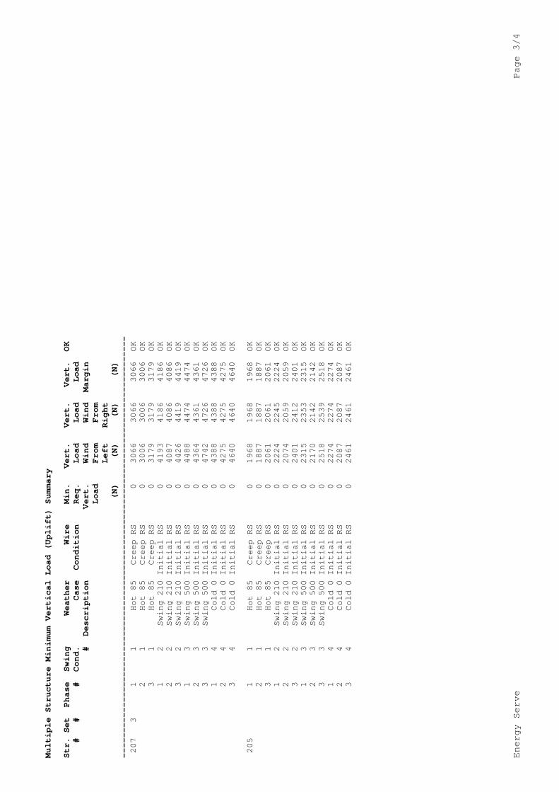
Energy Serve
Page 44
Page 29 May 2 2013
Appendix H ndash Endeavour Energy ndash David Mate ndash Email 25 March 2013
From David MateTo Kevin RuggSubject RE Centennial Coal - Angus Place - Subsidence Impact of Endeavour Energy 66kV Feeder 811Date Monday 25 March 2013 120800 PMAttachments image001png
Hi Kevin Based on the information in the report I have no issues in relation to the subsidence at AngusPlace
RegardsDavid David MateOverhead amp Underground Mains Manager ( 02 9853 6010Egrave 0413 227 4997 02 9853 6021 davidmateendeavourenergycomau 51 Huntingwood Drive Huntingwood NSW 2148 wwwendeavourenergycomau
From Kevin Rugg [mailtokevinenergyservecomau] Sent Monday 25 March 2013 1145 AMTo David MateSubject RE Centennial Coal - Angus Place - Subsidence Impact of Endeavour Energy 66kV Feeder811 Thanks David Thatrsquos all good but I am trying to find someone within Endeavour who will give us the all clear onthe subsidence impact assessment Cheers Kevin Rugg kevinenergyservecomau Energy ServeJemtom Pty Ltd(ABN 36 078 771 650)Ph (02) 6885 3224Fax (02) 6885 3210Mob 0427 853 224 This message is intended for the addressee named and may contain confidential information If you are not the intended

recipient please delete it and notify the sender From David Mate [mailtoDavidMateendeavourenergycomau] Sent Monday 25 March 2013 1135 AMTo Kevin RuggSubject RE Centennial Coal - Angus Place - Subsidence Impact of Endeavour Energy 66kV Feeder811 Hi Kevin The current rating of the line has a maximum operating temperature of 62degC the data has beensent to our regional staff to determine the most suitable way of increasing the clearances I will contact the our regional staff later this week to see what progress has occurred RegardsDavid
From Kevin Rugg [mailtokevinenergyservecomau] Sent Monday 25 March 2013 1117 AMTo David MateSubject FW Centennial Coal - Angus Place - Subsidence Impact of Endeavour Energy 66kV Feeder811 Hi David I believe the consideration of the attached report has fallen to you in regard to the subsidenceissues Kris Shankar has been following up the ground clearance issue found outside the subsidence zone Can you please confirm if this is so and whether any progress has been made Cheers Kevin Rugg kevinenergyservecomau Energy ServeJemtom Pty Ltd(ABN 36 078 771 650)Ph (02) 6885 3224Fax (02) 6885 3210Mob 0427 853 224 This message is intended for the addressee named and may contain confidential information If you are not the intendedrecipient please delete it and notify the sender From Kevin Rugg [mailtokevinenergyservecomau] Sent Friday 15 February 2013 847 AMTo markezzyendeavourenergycomauCc Adam WilliamsSubject FW Centennial Coal - Angus Place - Subsidence Impact of Endeavour Energy 66kV Feeder811 Hi Mark
I sent the email below to David Olley yesterday but I have since been advised that you will be theappropriate Endeavour contact person for this matter I have attached the report for your consideration and will follow up with a phone call shortly If I miss you can you please give me a call as soon as convenient Cheers Kevin Rugg kevinenergyservecomau Energy ServeJemtom Pty Ltd(ABN 36 078 771 650)Ph (02) 6885 3224Fax (02) 6885 3210Mob 0427 853 224 This message is intended for the addressee named and may contain confidential information If you are not the intendedrecipient please delete it and notify the sender From Kevin Rugg [mailtokevinenergyservecomau] Sent Thursday 14 February 2013 1226 PMTo davidolleyendeavourenergycomauCc Adam WilliamsSubject Centennial Coal - Angus Place - Subsidence Impact of Endeavour Energy 66kV Feeder 811 Hi David I have been engaged by Centennial Coal to undertake a review of potential subsidence impacts onFeeder 811 from the mining of LW900W at Angus Place Colliery The arrangement was originally that Centennial Coal were going to liaise with Endeavour Energybut now I have been asked to contact you directly to ensure that the attached report fully addressesEndeavourrsquos requirementsconcerns I have tried calling you today to discuss the report however there was no answer I will be out ofthe office for the rest of today but will call you tomorrow to follow up If however there is a time that best suits you to discuss the report please let me know Cheers Kevin Rugg kevinenergyservecomau Energy ServeJemtom Pty Ltd(ABN 36 078 771 650)Ph (02) 6885 3224Fax (02) 6885 3210Mob 0427 853 224 This message is intended for the addressee named and may contain confidential information If you are not the intendedrecipient please delete it and notify the sender
Longwall 900W Powerline Management Plan
This page has been intentionally left blank
Appendix 2 Addendum to Review
of Mine Subsidence
Impact of Longw
all 900W on Endeavour Energyrsquos 66kV
Feeder
CENTENNIAL COAL
Angus Place Colliery Wolgan Road Lidsdale
Addendum to
Review of Mine Subsidence Impact
Of Longwall 900W on Endeavour Energyrsquos
66kV Feeder 8112 ndash Springvale Colliery-Clarence Colliery
14 November 2013
Original Issue
Power System Engineering amp
Energy Advisory Services
Jemtom Pty Ltd ta Energy Serve bull ABN 36 078 771 650 Suite 1 Level 1 139 Macquarie Street Dubbo NSW 2830
Tel (02) 6885 3224 bull Fax (02) 6885 3210 bull Mobile 0427 853 224
Page 2 November 14 2013
Disclaimer Due to the unpredictable nature of mine subsidence Energy Serve is unable to accurately determine the behaviour of powerlines under the influence of such movements This report and the recommendations contained herein are based on the information provided and are intended to be sufficiently conservative to cater for the range of expected movements
It is not practical to predict the dynamic nature of the subsidence or all the possible intermediate outcomes hence it is recommended that regular inspection and monitoring is undertaken during and following longwall mining in the vicinity of the powerlines in question
Energy Serve will not be liable or responsible for any damage loss of revenue loss of production or unsafe conditions caused by mine subsidence on powerlines
Contents
Amendments 2 Background 3 Predicted Subsidence at Pole Locations 3 Results 3
Ground Clearance 5 Pole amp Conductor Loading 5
Summary 5 Recommendations 5
Amendments
Original issue Final Draft for client review 14112013
Page 3 November 14 2013
Background
Energy Serve has been commissioned by GSS Environmental on behalf of Centennial Coal ndash Angus Place Colliery to review the impact of the proposed mining of the Longwall 900 West (900W) on Endeavour Energyrsquos 66kV 8112 Feeder
This report is an addendum to the Final Report ndash Amendment A dated 2 May 2013 Reference should be made to the final Report for details on methodology and assumptions
The purpose of this addendum is to review the potential subsidence impacts due to an increase in nominal extraction height in Longwall 900W from 325m to 3425m
In addition to the data used to prepare the original report the following report was used to conduct this review
bull ldquoSubsidence Assessment Review for the Longwalls 900W and 910 Integrated SMPExtraction Plan Centennial Angus Place Collieryrdquo report by Ditton Geotechnical Services Pty Ltd (DgS) including predicted subsidence contours plus surface translation and rotations at each structure
Predicted Subsidence at Pole Locations
The following table of predicted subsidence translation and rotations were supplied by DgS The original and revised predictions are shown below
Pole ID
Final Subsidence due to 900W (mm)
Final Tilt Towards Longwall due to 900W (mmm)
Final Tilt Along Axis of Longwall
due to 900W (mmm)
Predicted Horizontal Movement
Towards Longwall due to 900W
(mm)
Predicted Horizontal
Movement Along Main Axis of
Longwall due to 900W (mm)
Orig Revised Orig Revised Orig Revised Orig Revised Orig Revised 201 0 0 0 0 0 0 0 0 0 0 202 0 0 0 0 0 0 0 0 0 0 203 0 10 0 02 0 0 0 3 0 0 204 30 70 03 06 03 02 5 9 5 3 205 720 770 83 125 65 67 133 201 103 107 206 1000 1080 55 84 -20 -21 -88 -135 -31 -34 207 380 410 74 108 -57 -60 -118 -173 -91 -96 208 40 80 04 06 -02 -01 -6 -10 -4 -2 209 0 10 0 02 0 -02 0 -3 0 3 210 0 0 0 0 0 0 0 0 0 0 211 0 0 0 0 0 0 0 0 0 0 Results
The maximum predicted surface subsidence to be experienced by the 66kV feeder has increased to 1080 mm at Pole 206 Subsidence is predicted to extend over a total route length of 970 metres but will exceed 200 mm over a distance of 360 metres only impacting poles 205-206-207 The poles 204 208 and 209 are within the predicted subsidence area but will be subject to insignificant impact
Page 4 November 14 2013
The figure below shows the impacted mains at a maximum operating temperature of 100degC and the post-subsidence ground profile for poles 204 to 207
Page 5 November 14 2013
Ground Clearance
It can be seen that there is more than adequate ground clearance in spite of the marginally increased subsidence and pole displacements rotations
The minimum ground clearance at 1000C within the subsidence zone is 88 metres
Pole amp Conductor Loading
Another potential issue with these spans is the impact of pole top movement of poles 205 206 amp 207 on the loading of structures and conductor tensions
Structure usages remain well within structure capacities Maximum usage is lt 75
Summary
The predicted pole movements and subsidence associated with the increased extraction height of Longwall 900W do not pose a problem with either ground clearance or structural integrity of any of the poles from 204 to 208 contained within the subsidence footprint No precautionary action is required and remedial action should not be necessary
Recommendations
It is not recommended that any precautionary actions be taken
The movement of these poles and the consequent action of the spans should be observed throughout the proposed mining and subsidence in order to validate the predictions and ensure clearances have been maintained at all times and structure loadings have not been exceeded
Following completion of the subsidence in this vicinity the final sags in the spans should be assessed as to whether they need to be corrected
In any case the powerline should be closely monitored throughout the mining subsidence process to ensure no unexpected hazards arise and statutory clearances are maintained
Kevin Rugg
Principal Consultant
Appendix 3 Stakeholder Consultation
Angus Place Colliery
PO Box 42
Wallerawang NSW 2845
- 1 Introduction
- 2 Purpose
- 3 Scope
- 4 Regulatory Requirements
-
- 41 Project Approval and Statement of Commitments
- 42 Mining Leases
- 43 Longwalls 930 ndash 980 SMP Approval
-
- 5 Relevant Feature(s) and Predicted Impacts
-
- 51 Relevant Feature(s)
- 52 Predicted Impacts
-
- 521 Subsidence Predictions
- 522 Specialist Powerline Impact Assessment
- 523 Subsidence Assessment Review
-
- 6 Identified Risks
- 7 Performance Measures and Indicators
-
- 71 Performance Measures
- 72 Performance Indicators
-
- 8 Management Measures
-
- 81 Endeavour Energy 66kV Powerline
- 82 Existing Erosion and Sedimentation Along Powerline Corridor
-
- 9 Monitoring Program
-
- 91 Baseline Monitoring
- 92 Monitoring Subsidence Impacts
- 93 Monitoring Environmental Consequences
- 94 Success of Remediation Measures
-
- 10 Consultation
- 11 Adaptive Management
- 12 Contingency Plan
- 13 Roles and Responsibilities
- 14 Reporting
- 15 Review
- 16 References
- Centennial Coal - Angus Place - LW900W Impact on Powerline 811_2 - 20130501pdf
-
- Amendments
- Background
- Methodology
- Predicted Subsidence at Pole Locations
- Results
-
- Existing Ground Clearance Issue outside Subsidence Area
- Ground Clearance
- Pole amp Conductor Loading
-
- Summary
- Recommendations
- Endeavour Energy Consultation amp Approval
- Appendix A ndash 66kV Feeder relative to Longwall 900 West (LW900W)
- Appendix B ndash Plan amp Profile ndash Pre-subsidence
- Appendix C ndash Plan amp Profile ndash Post-subsidence
- Appendix D ndash Section Usage Report ndash Existing
- Appendix E ndash Section Usage Report ndash Post-subsidence
- Appendix F ndash Structure Usage Report ndash Existing
- Appendix G ndash Structure Usage Report ndash Post-subsidence
- Appendix H ndash Endeavour Energy ndash David Mate ndash Email 25 March 2013
-
- Centennial Coal - Angus Place - LW900W Impact on Powerline 811_2 -Addendum - 20131114pdf
-
- Amendments
- Background
- Predicted Subsidence at Pole Locations
- Results
-
- Ground Clearance
- Pole amp Conductor Loading
-
- Summary
- Recommendations
-