LogiCORE™ SPI-4.2 Core v6application-notes.digchip.com/077/77-43557.pdf · SPI-4.2 v6.3 Getting...
58
R LogiCORE™ SPI-4.2 Core v6.3 Getting Started Guide UG231 February 15, 2006
Transcript of LogiCORE™ SPI-4.2 Core v6application-notes.digchip.com/077/77-43557.pdf · SPI-4.2 v6.3 Getting...
R
LogiCORE™SPI-4.2 Core v6.3
Getting Started GuideUG231 February 15, 2006

SPI-4.2 v6.3 Getting Started Guide www.xilinx.comUG231 February 15, 2006
"Xilinx" and the Xilinx logo shown above are registered trademarks of Xilinx, Inc. Any rights not expressly granted herein are reserved.
CoolRunner, RocketChips, Rocket IP, Spartan, StateBENCH, StateCAD, Virtex, XACT, XC2064, XC3090, XC4005, and XC5210 are registered trademarks of Xilinx, Inc.
The shadow X shown above is a trademark of Xilinx, Inc.
ACE Controller, ACE Flash, A.K.A. Speed, Alliance Series, AllianceCORE, Bencher, ChipScope, Configurable Logic Cell, CORE Generator, CoreLINX, Dual Block, EZTag, Fast CLK, Fast CONNECT, Fast FLASH, FastMap, Fast Zero Power, Foundation, Gigabit Speeds...and Beyond!, HardWire, HDL Bencher, IRL, J Drive, JBits, LCA, LogiBLOX, Logic Cell, LogiCORE, LogicProfessor, MicroBlaze, MicroVia, MultiLINX, NanoBlaze, PicoBlaze, PLUSASM, PowerGuide, PowerMaze, QPro, Real-PCI, RocketIO, SelectIO, SelectRAM, SelectRAM+, Silicon Xpresso, Smartguide, Smart-IP, SmartSearch, SMARTswitch, System ACE, Testbench In A Minute, TrueMap, UIM, VectorMaze, VersaBlock, VersaRing, Virtex-II Pro, Virtex-II EasyPath, Virtex-4, Wave Table, WebFITTER, WebPACK, WebPOWERED, XABEL, XACT-Floorplanner, XACT-Performance, XACTstep Advanced, XACTstep Foundry, XAM, XAPP, X-BLOX +, XC designated products, XChecker, XDM, XEPLD, Xilinx Foundation Series, Xilinx XDTV, Xinfo, XSI, XtremeDSP and ZERO+ are trademarks of Xilinx, Inc.
The Programmable Logic Company is a service mark of Xilinx, Inc.
All other trademarks are the property of their respective owners.
Xilinx, Inc. does not assume any liability arising out of the application or use of any product described or shown herein; nor does it convey any license under its patents, copyrights, or maskwork rights or any rights of others. Xilinx, Inc. reserves the right to make changes, at any time, in order to improve reliability, function or design and to supply the best product possible. Xilinx, Inc. will not assume responsibility for the use of any circuitry described herein other than circuitry entirely embodied in its products. Xilinx provides any design, code, or information shown or described herein "as is." By providing the design, code, or information as one possible implementation of a feature, application, or standard, Xilinx makes no representation that such implementation is free from any claims of infringement. You are responsible for obtaining any rights you may require for your implementation. Xilinx expressly disclaims any warranty whatsoever with respect to the adequacy of any such implementation, including but not limited to any warranties or representations that the implementation is free from claims of infringement, as well as any implied warranties of merchantability or fitness for a particular purpose. Xilinx, Inc. devices and products are protected under U.S. Patents. Other U.S. and foreign patents pending. Xilinx, Inc. does not represent that devices shown or products described herein are free from patent infringement or from any other third party right. Xilinx, Inc. assumes no obligation to correct any errors contained herein or to advise any user of this text of any correction if such be made. Xilinx, Inc. will not assume any liability for the accuracy or correctness of any engineering or software support or assistance provided to a user.
Xilinx products are not intended for use in life support appliances, devices, or systems. Use of a Xilinx product in such applications without the written consent of the appropriate Xilinx officer is prohibited.
The contents of this manual are owned and copyrighted by Xilinx. Copyright 1994-2006 Xilinx, Inc. All Rights Reserved. Except as stated herein, none of the material may be copied, reproduced, distributed, republished, downloaded, displayed, posted, or transmitted in any form or by any means including, but not limited to, electronic, mechanical, photocopying, recording, or otherwise, without the prior written consent of Xilinx. Any unauthorized use of any material contained in this manual may violate copyright laws, trademark laws, the laws of privacy and publicity, and communications regulations and statutes.
R

www.xilinx.com SPI-4.2 v6.3 Getting Started GuideUG231 February 15, 2006
Revision History
The following table shows the revision history for this document.
Date Version Revision
2/15/06 1.0 Initial Xilinx release.

www.xilinx.com SPI-4.2 v6.3 Getting Started GuideUG231 February 15, 2006
Preface: About This GuideContents . . . . . . . . . . . . . . . . . . . . . . . . . . . . . . . . . . . . . . . . . . . . . . . . . . . . . . . . . . . . . . . . . . . . . 3Additional Resources . . . . . . . . . . . . . . . . . . . . . . . . . . . . . . . . . . . . . . . . . . . . . . . . . . . . . . . . 4Conventions . . . . . . . . . . . . . . . . . . . . . . . . . . . . . . . . . . . . . . . . . . . . . . . . . . . . . . . . . . . . . . . . . 4
Typographical . . . . . . . . . . . . . . . . . . . . . . . . . . . . . . . . . . . . . . . . . . . . . . . . . . . . . . . . . . . . . 4Online Document . . . . . . . . . . . . . . . . . . . . . . . . . . . . . . . . . . . . . . . . . . . . . . . . . . . . . . . . . . 6
Chapter 1: IntroductionAbout the Core . . . . . . . . . . . . . . . . . . . . . . . . . . . . . . . . . . . . . . . . . . . . . . . . . . . . . . . . . . . . . . . 7Recommended Design Experience . . . . . . . . . . . . . . . . . . . . . . . . . . . . . . . . . . . . . . . . . . . . 7Additional Core Resources . . . . . . . . . . . . . . . . . . . . . . . . . . . . . . . . . . . . . . . . . . . . . . . . . . . 7Technical Support. . . . . . . . . . . . . . . . . . . . . . . . . . . . . . . . . . . . . . . . . . . . . . . . . . . . . . . . . . . . 8Feedback. . . . . . . . . . . . . . . . . . . . . . . . . . . . . . . . . . . . . . . . . . . . . . . . . . . . . . . . . . . . . . . . . . . . . 8
Core . . . . . . . . . . . . . . . . . . . . . . . . . . . . . . . . . . . . . . . . . . . . . . . . . . . . . . . . . . . . . . . . . . . . . 8Document . . . . . . . . . . . . . . . . . . . . . . . . . . . . . . . . . . . . . . . . . . . . . . . . . . . . . . . . . . . . . . . . 8
Chapter 2: Installing and Licensing the CoreSystem Requirements . . . . . . . . . . . . . . . . . . . . . . . . . . . . . . . . . . . . . . . . . . . . . . . . . . . . . . . . 9Before You Begin . . . . . . . . . . . . . . . . . . . . . . . . . . . . . . . . . . . . . . . . . . . . . . . . . . . . . . . . . . . . 9Installing the Core . . . . . . . . . . . . . . . . . . . . . . . . . . . . . . . . . . . . . . . . . . . . . . . . . . . . . . . . . . . 9
CORE Generator IP Updates Installer . . . . . . . . . . . . . . . . . . . . . . . . . . . . . . . . . . . . . . . 10Manual Installation . . . . . . . . . . . . . . . . . . . . . . . . . . . . . . . . . . . . . . . . . . . . . . . . . . . . . . . 10
Verifying the Installation . . . . . . . . . . . . . . . . . . . . . . . . . . . . . . . . . . . . . . . . . . . . . . . . . . . 10License Options . . . . . . . . . . . . . . . . . . . . . . . . . . . . . . . . . . . . . . . . . . . . . . . . . . . . . . . . . . . . . 11
Simulation-Only Evaluation . . . . . . . . . . . . . . . . . . . . . . . . . . . . . . . . . . . . . . . . . . . . . . . . 11Full System Hardware Evaluation . . . . . . . . . . . . . . . . . . . . . . . . . . . . . . . . . . . . . . . . . . 12Full . . . . . . . . . . . . . . . . . . . . . . . . . . . . . . . . . . . . . . . . . . . . . . . . . . . . . . . . . . . . . . . . . . . . . 12
Obtaining Your License . . . . . . . . . . . . . . . . . . . . . . . . . . . . . . . . . . . . . . . . . . . . . . . . . . . . . 12Installing Your License File . . . . . . . . . . . . . . . . . . . . . . . . . . . . . . . . . . . . . . . . . . . . . . . . . 13
Chapter 3: Quick Start Example DesignOverview . . . . . . . . . . . . . . . . . . . . . . . . . . . . . . . . . . . . . . . . . . . . . . . . . . . . . . . . . . . . . . . . . . . 15Generating the Core . . . . . . . . . . . . . . . . . . . . . . . . . . . . . . . . . . . . . . . . . . . . . . . . . . . . . . . . . 15Implementing the Example Design . . . . . . . . . . . . . . . . . . . . . . . . . . . . . . . . . . . . . . . . . . 17Running the Simulation . . . . . . . . . . . . . . . . . . . . . . . . . . . . . . . . . . . . . . . . . . . . . . . . . . . . . 17
Setting up for Simulation . . . . . . . . . . . . . . . . . . . . . . . . . . . . . . . . . . . . . . . . . . . . . . . . . . 17Functional Simulation . . . . . . . . . . . . . . . . . . . . . . . . . . . . . . . . . . . . . . . . . . . . . . . . . . . . . 17Timing Simulation . . . . . . . . . . . . . . . . . . . . . . . . . . . . . . . . . . . . . . . . . . . . . . . . . . . . . . . . 18
Table of Contents

www.xilinx.com SPI-4.2 v6.3 Getting Started GuideUG231 February 15, 2006
Chapter 4: Detailed Example DesignDirectory Structure . . . . . . . . . . . . . . . . . . . . . . . . . . . . . . . . . . . . . . . . . . . . . . . . . . . . . . . . . . 19
Project Directory (<project_dir>) . . . . . . . . . . . . . . . . . . . . . . . . . . . . . . . . . . . . . . . . . . . . 19Implementation and Simulation Scripts . . . . . . . . . . . . . . . . . . . . . . . . . . . . . . . . . . . . . 23
Simulation Script Details. . . . . . . . . . . . . . . . . . . . . . . . . . . . . . . . . . . . . . . . . . . . . . . . . . . 23Example Design Configuration . . . . . . . . . . . . . . . . . . . . . . . . . . . . . . . . . . . . . . . . . . . . . . 24
Loopback Module . . . . . . . . . . . . . . . . . . . . . . . . . . . . . . . . . . . . . . . . . . . . . . . . . . . . . . . . 24Basic Loopback Operation . . . . . . . . . . . . . . . . . . . . . . . . . . . . . . . . . . . . . . . . . . . . . . . . . 24
Demonstration Test Bench . . . . . . . . . . . . . . . . . . . . . . . . . . . . . . . . . . . . . . . . . . . . . . . . . . 25Clock Generator . . . . . . . . . . . . . . . . . . . . . . . . . . . . . . . . . . . . . . . . . . . . . . . . . . . . . . . . . . 26Startup Module. . . . . . . . . . . . . . . . . . . . . . . . . . . . . . . . . . . . . . . . . . . . . . . . . . . . . . . . . . . 27Stimulus Module . . . . . . . . . . . . . . . . . . . . . . . . . . . . . . . . . . . . . . . . . . . . . . . . . . . . . . . . . 28Procedures Module . . . . . . . . . . . . . . . . . . . . . . . . . . . . . . . . . . . . . . . . . . . . . . . . . . . . . . . 29Data Monitor . . . . . . . . . . . . . . . . . . . . . . . . . . . . . . . . . . . . . . . . . . . . . . . . . . . . . . . . . . . . . 29Status Monitor . . . . . . . . . . . . . . . . . . . . . . . . . . . . . . . . . . . . . . . . . . . . . . . . . . . . . . . . . . . 29Customizing the Demonstration Test Bench . . . . . . . . . . . . . . . . . . . . . . . . . . . . . . . . . . 30Testcase Package . . . . . . . . . . . . . . . . . . . . . . . . . . . . . . . . . . . . . . . . . . . . . . . . . . . . . . . . . 30Testcase Module . . . . . . . . . . . . . . . . . . . . . . . . . . . . . . . . . . . . . . . . . . . . . . . . . . . . . . . . . . 32Calendar Sequence Files (Sink and Source) . . . . . . . . . . . . . . . . . . . . . . . . . . . . . . . . . . . 33
Appendix A: VHDL DetailsProcedures Module . . . . . . . . . . . . . . . . . . . . . . . . . . . . . . . . . . . . . . . . . . . . . . . . . . . . . . . . . 35
Appendix B: Verilog DetailsProcedures Module . . . . . . . . . . . . . . . . . . . . . . . . . . . . . . . . . . . . . . . . . . . . . . . . . . . . . . . . . 39Random Testcase Sample Code. . . . . . . . . . . . . . . . . . . . . . . . . . . . . . . . . . . . . . . . . . . . . . 41
Appendix C: SPI-4.2 File Descriptions
Appendix D: Data and Status Monitor Warnings

www.xilinx.com SPI-4.2 v6.3 Getting Started GuideUG231 February 15, 2006
Chapter 1: Introduction
Chapter 2: Installing and Licensing the Core
Chapter 3: Quick Start Example Design
Chapter 4: Detailed Example DesignTable 4-1: Testcase Package User-Defined Constants . . . . . . . . . . . . . . . . . . . . . . . . . . . . . . 30Table 4-2: Useful Testcase Signals. . . . . . . . . . . . . . . . . . . . . . . . . . . . . . . . . . . . . . . . . . . . . . . 32Table 4-3: Testcase Module Request Signals . . . . . . . . . . . . . . . . . . . . . . . . . . . . . . . . . . . . . 33
Appendix A: VHDL DetailsTable A-1: send_packet (PBr, addr, bytes) Inputs. . . . . . . . . . . . . . . . . . . . . . . . . . . . . . . . . . 35Table A-2: send_user_data (PBr, SOP, EOP, Err, Addr, bytes) Inputs . . . . . . . . . . . . . . . . 36Table A-3: send_idles (PBr, cycles) Inputs . . . . . . . . . . . . . . . . . . . . . . . . . . . . . . . . . . . . . . . . 36Table A-4: send_training (PBr, patterns) Inputs . . . . . . . . . . . . . . . . . . . . . . . . . . . . . . . . . . . 36Table A-5: sop_spacing Inputs . . . . . . . . . . . . . . . . . . . . . . . . . . . . . . . . . . . . . . . . . . . . . . . . . . 36Table A-6: send_status (PBt, channel, value) Inputs . . . . . . . . . . . . . . . . . . . . . . . . . . . . . . . 37Table A-7: get_status (PBt, channel) Inputs . . . . . . . . . . . . . . . . . . . . . . . . . . . . . . . . . . . . . . . 37
Appendix B: Verilog DetailsTable B-1: send_packet (Addr, bytes) Inputs. . . . . . . . . . . . . . . . . . . . . . . . . . . . . . . . . . . . . . 39Table B-2: send_user_data (SOP, EOP, Err, Addr, bytes) Inputs . . . . . . . . . . . . . . . . . . . . . 39Table B-3: send_idles (cycles) Inputs . . . . . . . . . . . . . . . . . . . . . . . . . . . . . . . . . . . . . . . . . . . . 40Table B-4: send_training (patterns) Inputs . . . . . . . . . . . . . . . . . . . . . . . . . . . . . . . . . . . . . . . 40Table B-5: sop_spacing (Bytes1, Err1, Addr1, EOP2, Err2, Addr2, Bytes2, num_cycles) Inputs 40Table B-6: send_status (channel, value) Inputs. . . . . . . . . . . . . . . . . . . . . . . . . . . . . . . . . . . . 41Table B-7: get_status (channel) Inputs . . . . . . . . . . . . . . . . . . . . . . . . . . . . . . . . . . . . . . . . . . . 41
Appendix C: SPI-4.2 File Descriptions
Appendix D: Data and Status Monitor Warnings

www.xilinx.com SPI-4.2 v6.3 Getting Started GuideUG231 February 15, 2006
Chapter 1: Introduction
Chapter 2: Installing and Licensing the CoreFigure 2-1: CORE Generator Window . . . . . . . . . . . . . . . . . . . . . . . . . . . . . . . . . . . . . . . . . . . 11
Chapter 3: Quick Start Example DesignFigure 3-1: Core Customization GUI Main Window. . . . . . . . . . . . . . . . . . . . . . . . . . . . . . . 16
Chapter 4: Detailed Example DesignFigure 4-1: SPI-4.2 Directory Structure. . . . . . . . . . . . . . . . . . . . . . . . . . . . . . . . . . . . . . . . . . . 19Figure 4-2: Example Design Configuration . . . . . . . . . . . . . . . . . . . . . . . . . . . . . . . . . . . . . . . 24Figure 4-3: Demonstration Test Bench Connections . . . . . . . . . . . . . . . . . . . . . . . . . . . . . . . 25Figure 4-4: Test bench Modules. . . . . . . . . . . . . . . . . . . . . . . . . . . . . . . . . . . . . . . . . . . . . . . . . 26Figure 4-5: Startup State Diagram . . . . . . . . . . . . . . . . . . . . . . . . . . . . . . . . . . . . . . . . . . . . . . . 27
Appendix A: VHDL Details
Appendix B: Verilog Details
Appendix C: SPI-4.2 File Descriptions
Appendix D: Data and Status Monitor Warnings
List of Figures
SPI-4.2 v6.3 Getting Started Guide www.xilinx.com 3UG231 February 15, 2006
R
Preface
About This Guide
This guide provides information about generating the Xilinx LogiCORE™ SPI-4.2 core (targeting VirtexTM-II and Virtex-II Pro), customizing and simulating the core using the provided example design, and running the design files through implementation using the Xilinx tools.
ContentsThis guide contains the following chapters:
• Preface, “About this Guide” introduces the organization and purpose of the Getting Started Guide, a list of additional resources, and the conventions used in this document.
• Chapter 1, “Introduction” describes the core and related information, including recommended design experience, additional resources, technical support, and submitting feedback to Xilinx.
• Chapter 2, “Installing and Licensing the Core” provides information about installing and licensing the core.
• Chapter 3, “Quick Start Example Design” provides instructions to quickly generate the core and run the example design through implementation and simulation using the default settings.
• Chapter 4, “Detailed Example Design” describes the demonstration test bench in detail and provides directions for how to customize the demonstration test bench for use in an application.
• Appendix A, “VHDL Details” provides details about the VHDL demonstration test bench and how to customize it.
• Appendix B, “Verilog Details” provides details about the Verilog demonstration test bench and how to customize it.
• Appendix C, “SPI-4.2 File Descriptions” provides details about the core directory and files.
• Appendix D, “Data and Status Monitor Warnings” describes the common demonstration test bench warnings.

4 www.xilinx.com SPI-4.2 v6.3 Getting Started GuideUG231 February 15, 2006
Preface: About This GuideR
Additional ResourcesFor additional information, go to http://support.xilinx.com. The following table lists some of the resources you can access from this website. You can also directly access these resources using the provided URLs.
ConventionsThis document uses the following conventions. An example illustrates each convention.
TypographicalThe following typographical conventions are used in this document:
Resource Description/URL
Tutorials Tutorials covering Xilinx design flows, from design entry to verification and debugging
www.support.xilinx.com/support/techsup/tutorials/index.htm
Answer Browser Database of Xilinx solution records
www.support.xilinx.com/xlnx/xil_ans_browser.jsp
Application Notes Descriptions of device-specific design techniques and approaches
www.xilinx.com/xlnx/xweb/xil_publications_index.jsp?category=Application+Notes
Data Sheets Device-specific information on Xilinx device characteristics, including readback, boundary scan, configuration, length count, and debugging
www.support.xilinx.com/xlnx/xweb/xil_publications_index.jsp
Problem Solvers Interactive tools that allow you to troubleshoot your design issues
www.support.xilinx.com/support/troubleshoot/psolvers.htm
Tech Tips Latest news, design tips, and patch information for the Xilinx design environment
www.support.xilinx.com/xlnx/xil_tt_home.jsp
Convention Meaning or Use Example
Courier fontMessages, prompts, and program files that the system displays
speed grade: - 100
Courier boldLiteral commands that you enter in a syntactical statement ngdbuild design_name

SPI-4.2 v6.3 Getting Started Guide www.xilinx.com 5UG231 February 15, 2006
ConventionsR
Italic font
Variables in a syntax statement for which you must supply values
ngdbuild design_name
References to other manualsSee the Development System Reference Guide for more information.
Emphasis in textIf a wire is drawn so that it overlaps the pin of a symbol, the two nets are not connected.
Square brackets [ ]
An optional entry or parameter. However, in bus specifications, such as bus[7:0], they are required.
ngdbuild [option_name] design_name
Braces { } A list of items from which you must choose one or more lowpwr ={on|off}
Vertical bar | Separates items in a list of choices lowpwr ={on|off}
Vertical ellipsis...
Repetitive material that has been omitted
IOB #1: Name = QOUT’ IOB #2: Name = CLKIN’...
Horizontal ellipsis . . . Repetitive material that has been omitted
allow block block_name loc1 loc2 ... locn;
Convention Meaning or Use Example

6 www.xilinx.com SPI-4.2 v6.3 Getting Started GuideUG231 February 15, 2006
Preface: About This GuideR
Online DocumentThe following conventions are used in this document:
Convention Meaning or Use Example
Blue textCross-reference link to a location in the current document
See the section “Additional Resources” for details.
Refer to “Title Formats” in Chapter 1 for details.
Blue, underlined text Hyperlink to a website (URL) Go to http://www.xilinx.com for the latest speed files.

SPI-4.2 v6.3 Getting Started Guide www.xilinx.com 7UG231 February 15, 2006
R
Chapter 1
Introduction
The Xilinx LogiCORE™ SPI-4.2 (PL4) core is a fully-verified design solution that supports Verilog and VHDL. The example design in this guide is provided in both Verilog and VHDL.
This chapter introduces the SPI-4.2 core and provides related information, including recommended design experience, additional resources, technical support, and how to submit feedback to Xilinx.
About the CoreThe SPI-4.2 core is a Xilinx CORE Generator™ IP core, (targeting Virtex-II and Virtex-II Pro) that can be downloaded from the SPI-4.2 v6.3 product lounge.
For detailed information about the core, see
www.xilinx.com/ipcenter/posphyl4/spi42_core.htm.
For information about system requirements, installation, and licensing options, see Chapter 2, “Installing and Licensing the Core.”
Recommended Design ExperienceAlthough the SPI-4.2 core is a fully-verified solution, the challenges associated with implementing a complete design vary, depending on desired configuration and functionality. For best results, previous experience building high-performance, pipelined FPGA designs using Xilinx implementation software and user constraints files (UCF) is recommended.
Contact your local Xilinx representative for a closer review and estimate of the effort required to meet your specific design requirements.
Additional Core ResourcesFor detailed information and updates about the SPI-4.2 core, see the following additional documents located on the SPI-4.2 product lounge page at:
http://www.xilinx.com/ipcenter/posphyl4/spi42_core.htm.
• LogiCORE SPI-4.2 Data Sheet
• LogiCORE SPI-4.2 Release Notes
For updates to this document, see the LogiCORE SPI-4.2 Getting Started Guide, also located on the Xilinx SPI-4.2 product page.

8 www.xilinx.com SPI-4.2 v6.3 Getting Started GuideUG231 February 15, 2006
Chapter 1: IntroductionR
Technical SupportTo obtain technical support specific to the SPI-4.2 core, visit http://support.xilinx.com/. Questions are routed to a team of engineers with expertise using the SPI-4.2 core.
Xilinx will provide technical support for use of this product as described in the SPI-4.2 Data Sheet and the SPI-4.2 Getting Started Guide. Xilinx cannot guarantee timing, functionality, or support of this product for designs outside the guidelines presented in this document.
FeedbackXilinx welcomes comments and suggestions about the SPI-4.2 core and the documentation provided with the core.
CoreFor comments or suggestions about the SPI-4.2 core, please submit a WebCase from http://support.xilinx.com/. Be sure to include the following information:
• Product name
• Core version number
• Explanation of your comments
DocumentFor comments or suggestions about this document, please submit a WebCase from http://support.xilinx.com/. Be sure to include the following information:
• Document title
• Document number
• Page number(s) to which your comments refer
• Explanation of your comments
SPI-4.2 v6.3 Getting Started Guide www.xilinx.com 9UG231 February 15, 2006
R
Chapter 2
Installing and Licensing the Core
This chapter provides instructions for installing the SPI-4.2 core and obtaining a license for the core so that you can use the core in a design. The SPI-4.2 core is provided under the terms of the Xilinx LogiCORE Site License Agreement. This license agreement conforms to the terms of the SignOnce IP License standard defined by the Common License Consortium. Purchase of the core entitles you to technical support and access to updates for a period of one year.
System Requirements
Windows
• Windows® 2000 Professional with Service Pack 2-4
• Windows XP Professional with Service Pack 1
Solaris/Linux
• Sun Solaris® 8/9
• Red Hat® Enterprise Linux 3.0 (32-bit and 64-bit)
Software
• Xilinx ISETM 8.1i
Before You BeginBefore installing the core, you must have a Xilinx.com account and the ISE 8.1i software installed on your system. If you have already completed these steps, go to “Installing the Core.”
1. Click Login at the top of the Xilinx home page; then follow the onscreen instructions to create a support account.
2. Install the ISE 8.1i software and the applicable Service Pack software. ISE Service Packs can be downloaded from www.xilinx.com/support/download.htm.
Installing the CoreYou can install the core in two ways—using the CORE Generator IP Updates Installer, which lets you select from a list of updates, or by performing a manual installation after downloading the core from the web.

10 www.xilinx.com SPI-4.2 v6.3 Getting Started GuideUG231 February 15, 2006
Chapter 2: Installing and Licensing the CoreR
CORE Generator IP Updates InstallerNote: To use this installation method behind a firewall, you must know your proxy settings. Contact your administrator to determine the proxy host address and port number before you begin if necessary.
1. Start the CORE Generator; then open an existing project or create a new one.
2. From the main CORE Generator window, choose Tools > Updates Installer to start the Updates Installer. If you are behind a firewall, you will be prompted to enter your proxy host and port settings.
3. If prompted, enter your proxy settings; then click Set. The IP Updates installer appears.
4. Click the checkbox next to 8.1i_IP_Update1 to select it; then click Install Selected. Informational messages may appear indicating that additional installations are required.
5. Click OK to accept any messages and continue. The User Login dialog box appears.
6. Enter your login name and password; then click OK. The Updates Installer Generator downloads and installs the selected products, and then exits.
7. To confirm the installation, check the following file: C:\Xilinx\coregen\install\install_history. Note that this step assumes your Xilinx software is installed in C:\Xilinx.
Manual Installation1. Close the CORE Generator application if it is running.
2. Download the IP Update ZIP file from the following location and save it to a temporary directory: www.xilinx.com/xlnx/xil_sw_updates_home.jsp?update=ip&software=8.1i
3. Unpack the ZIP files using either WinZip (Windows) or Unzip (UNIX).
4. Extract the ZIP file (ise_81i_ip_update1.zip) archive to the root directory of your Xilinx software installation. (Allow the extractor utility you use to overwrite all existing files and maintain the directory structure defined in the archive.)
5. If you do not have a zip utility, do one of the following:
− Windows. From a command window, type the following:%XILINX%/bin/nt/unzip -d %XILINX% ise_81i_ip_update1.zip
− Linux. From a UNIX shell, type the following: $XILINX/bin/lin/unzip -d $XILINX ise_81i_ip_update1.zip
− Solaris. From a UNIX shell, type the following: $XILINX/bin/sol/unzip -d $XILINX ise_81i_ip_update1.zip
6. To verify the root directory of your Xilinx installation, do one of the following:
− Windows. Type echo %XILINX% from a DOS prompt.
− UNIX. If you have already installed the Xilinx ISE software, the Xilinx variable defined by your set-up script identifies the location of the Xilinx installation directory. After sourcing the Xilinx set-up script, type echo $XILINX to determine the location of the Xilinx installation.
Verifying the Installation1. Start the CORE Generator.

SPI-4.2 v6.3 Getting Started Guide www.xilinx.com 11UG231 February 15, 2006
License OptionsR
2. After creating a new project or opening an existing one, the IP core functional categories appear at the left side of the window.
3. Click to expand or collapse the view of individual functional categories, or click the View by Name tab at the bottom of the list to see an alphabetical list of all cores in all categories.
4. To view specific versions of the cores, choose an option from the Show drop-down list at the top of the window:
− Latest Versions. Display the latest versions of all cores.
− All Versions. Display all versions of cores, including new cores and new versions of cores.
− All Versions including Obsolete. Display all cores, including those scheduled to become obsolete.
5. Determine if the installation was successful by verifying that the new core or cores appear in the CORE Generator GUI.
For additional assistance installing the IP Update, contact www.xilinx.com/support.
License OptionsThe SPI-4.2 core provides three licensing options, described in the following sections.
Simulation-Only EvaluationThe Simulation-Only Evaluation license is provided with the Xilinx CORE Generator system. This license lets you evaluate core functionality using a provided example design.
Figure 2-1: CORE Generator Window
FunctionalCategories
Viewing Options
View by Name

12 www.xilinx.com SPI-4.2 v6.3 Getting Started GuideUG231 February 15, 2006
Chapter 2: Installing and Licensing the CoreR
You can also use your own design and simulate the various interfaces on the core. Functional simulation is supported by a dynamically generated gate-level netlist.
Full System Hardware EvaluationThe Full System Hardware Evaluation license is available at no cost and lets you fully integrate the core into an FPGA design, place and route the design, evaluate timing, and perform back-annotated gate-level simulation using the demonstration test bench provided.
In addition, the license lets you generate a bitstream from the placed and routed design, which can then be downloaded to a supported device and tested in hardware. The core can be tested in the target device for a limited time before timing out. The core can be reactivated by re-configuring the device after a time out.
You can obtain the Full System Evaluation License in one of the following ways, depending on the core:
• By registering on the Xilinx IP Evaluation page and filling out a form to request an automatically-generated evaluation license
• By contacting your local Xilinx FAE to request a Full System Hardware Evaluation license key
Click Evaluate on the associated core product page for information about obtaining a Full System Hardware Evaluation License.
Full The Full license is provided when you purchase the core. This option provides full access to all core functionality both in simulation and in hardware, including:
• Gate-level functional simulation support
• Back annotated gate-level simulation support
• Full implementation support including place and route and bitstream generation
• Full functionality in the programmed device with no time-outs
Obtaining Your License
Obtaining a Simulation-Only or Full System Hardware Evaluation License
To obtain a Simulation-Only or Full System Hardware Evaluation license, do the following:
• Navigate to the SPI-4.2 product page: www.xilinx.com/ipcenter/posphyl4/spi42_core.htm.
• Click Evaluate.• Select one of the following:
− Simulation-Only Evaluation
− Full System Hardware Evaluation
For both types of licenses, follow the onscreen instructions to both download the CORE Generator files (delivered as an IP update) and satisfy any additional requirements associated with the license type.
SPI-4.2 v6.3 Getting Started Guide www.xilinx.com 13UG231 February 15, 2006
Installing Your License FileR
Obtaining a Full License
To obtain a Full license, you must purchase the core. After purchase, you will receive a letter containing a serial number. This serical number is used to register for access to the lounge, a secured area of the SPI-4.2 product page.
• From the product page, click Register to register and request access to the lounge. • Xilinx will review your access request. Requests for access are typically granted
within 48 hours. Contact Xilinx Customer Service if you need faster turnaround. • After you receive confirmation of lounge access, click Access Lounge on the SPI-4.2
product page and log in.
Follow the instructions in the lounge to fill out the license request form; then click Submit to automatically generate the license. An email containing the license and installation instructions will be sent to you immediately.
Installing Your License FileAfter selecting a license option, an email is sent to your login account that includes instructions for installing your license file. In addition, information about advanced licensing options and technical support is provided.

14 www.xilinx.com SPI-4.2 v6.3 Getting Started GuideUG231 February 15, 2006
Chapter 2: Installing and Licensing the CoreR
SPI-4.2 v6.3 Getting Started Guide www.xilinx.com 15UG231 February 15, 2006
R
Chapter 3
Quick Start Example Design
The quick start steps provide information to quickly generate a SPI-4.2 core, run the design through implementation with the Xilinx tools, and simulate the example design using the provided demonstration test bench. For more detailed information about this example design, see Chapter 4, “Detailed Example Design.”
OverviewThe SPI-4.2 example design consists of the following:
• SPI-4.2 Sink and Source core netlists
• SPI-4.2 Sink and Source core simulation models
• Example HDL wrapper (which instantiates the cores and example design)
• Customizable demonstration test bench to simulate the example design
Generating the CoreTo generate a SPI-4.2 core with default values using the Xilinx CORE Generator system, do the following:
1. Start the CORE Generator system.
For help starting and using the CORE Generator system, see the Xilinx CORE Generator Guide, available from the ISE documentation.
2. Choose File > New Project.
3. Type a directory name. For this example design, use the directory name design.
4. Set the following project options:
♦ Part Options
- From Target Architecture, select the Virtex-II or Virtex-II Pro family.
Note: If an unsupported silicon family is selected, the SPI-4.2 core will not appear in the taxonomy tree.
Note: The Device, Package and Speed Grade selected in the Part Options tab have no effect on the generated core. The core is delivered with an example UCF targeting the device and package selected in the GUI of the core.
♦ Generation Options
- For Design Entry, select either VHDL or Verilog.
- For Vendor, select Synplicity or Other (for XST).

16 www.xilinx.com SPI-4.2 v6.3 Getting Started GuideUG231 February 15, 2006
Chapter 3: Quick Start Example DesignR
5. Using the Show box in the tool bar, customize to display all versions of the core. If you have SPI-4.2 v7.4 of the core installed, perform this step so that you can view the v6.3 core.
6. After creating the project, locate the directory containing the SPI-4.2 core in the taxonomy tree; it appears under Communications & Networking > Telecommunications > SPI-4.2.
7. Double-click the core to bring up the customization GUI.
8. In the Component Name field, enter a name for the core instance. (In this example, the name quickstart is used.)
9. After selecting the desired features and parameters from the GUI screens, click Generate.
The cores and supporting files, including the example design, are generated in the project directory. For detailed information and an illustration of the example design files and directories produced, see “Directory Structure” in Chapter 4.
Figure 3-1: Core Customization GUI Main Window

SPI-4.2 v6.3 Getting Started Guide www.xilinx.com 17UG231 February 15, 2006
Implementing the Example DesignR
Implementing the Example DesignAfter generating a core with a Full System Hardware Evaluation or Full license, the netlists and the example design can be processed by the Xilinx implementation tools. The generated output files include scripts to assist the user in running the Xilinx tools.
To implement the SPI-4.2 example design, open a command prompt or terminal window and type the following commands:
For Windows
ms-dos> cd <proj>\<quickstart>\implementms-dos> implement.bat
For UNIX
unix-shell% cd <proj>/<quickstart>/implementunix-shell% ./implement.sh
These commands execute a script that synthesizes, builds, maps, and place-and-routes the example design. The script then generates a post-par simulation model for use in timing simulation. The resulting files are placed in the results directory.
Running the Simulation Using the provided example design, the user can quickly simulate and observe the behavior of the SPI-4.2 core. There are two different simulation types, functional and timing. The simulation models provided are either in VHDL or Verilog, depending on the CORE Generator Design Entry project option selected by the user.
Setting up for SimulationThe Xilinx UniSim and SimPrim libraries must be mapped into the simulator. If the UniSim or SimPrim libraries are not set for the test environment, go to www.xilinx.com/support, where the following solution records are located:
• Compiling Xilinx Simulation Libraries (MTI) - Answer Record 2561
• Compiling Xilinx Simulation Libraries (NC-SIM) - Answer Record 2554
Functional SimulationInstructions for running a functional simulation of the SPI-4.2 core using either VHDL or Verilog are given below. Functional simulation models are provided when the core is generated. Note that implementing the core before simulating the functional models is not required. If a configuration file (referenced in the CORE Generator GUI as the COE file) was used to program the calendar, special steps are required to include the calendar sequence in the simulation. See the SPI-4.2 Core Data Sheet for details on including the calendar initialization values in simulation.
To run a VHDL or Verilog functional simulation of the example design using MTI:
1. Set the current directory to:
<quickstart>/simulation/functional/
2. Launch the ModelSim® simulator.
3. Launch the simulation script:
modelsim> do simulate_mti.do

18 www.xilinx.com SPI-4.2 v6.3 Getting Started GuideUG231 February 15, 2006
Chapter 3: Quick Start Example DesignR
The simulation script compiles the functional simulation models, the loopback and the demonstration test bench, adds relevant signals to the wave window, and runs the simulation. To observe the operation of the core, inspect the simulation transcript and the waveform.
Note that you can only run a timing simulation on a Sink core with dynamic alignment. To simulate DPA alignment core, use timing simulation or static alignment during functional simulation.
Timing SimulationTiming simulation is available only with purchase of the core (Full license) or with access to the Full System Hardware Evaluation license. With a Simulation Only Evaluation license the core cannot be run through the implementation tools, which is required for timing based simulation.
Instructions for running a timing simulation of the SPI-4.2 core using either VHDL or Verilog are given below. A timing simulation model is generated when the core is run through the Xilinx tools using the implement script. Calendar information specified in a COE file is included in the timing simulation netlist.
To run a VHDL or Verilog functional simulation of the example design using MTI:
1. Set the current directory to:
<quickstart>/simulation/timing/
2. Launch the ModelSim simulator.
3. Launch the simulation script:
modelsim> do simulate_mti.do
The simulation script compiles the timing simulation model and the demonstration test bench, adds relevant signals to the wave window, and runs the simulation. To observe the operation of the core, inspect the simulation transcript and the waveform.

SPI-4.2 v6.3 Getting Started Guide www.xilinx.com 19UG231 February 15, 2006
R
Chapter 4
Detailed Example Design
This chapter provides detailed information about the example design. The example design includes a description of the files and the directory structure generated by the Xilinx CORE Generator system, the purpose and contents of the provided scripts, the contents of the example HDL wrappers, and the operation of the demonstration test bench.
Directory StructureFigure 4-1 shows the files and directories created by CORE Generator. The CORE Generator project directory is <proj_dir>, and the component name, entered in the SPI-4.2 core customization dialog box, is <component_name>.
Project Directory (<project_dir>)The CORE Generator system provides the resulting Sink and Source core files in the <proj_dir> directory. The EDIF files are the resulting core netlists, the VHDL and Verilog files are the functional simulation models, and the VHO and VEO files are instantiation templates.
<component_name>_pl4_snk_top.edf
Figure 4-1: SPI-4.2 Directory Structure
<component_name>_pl4_snk_top.edf<component_name>_pl4_src_top.edf<component_name>_pl4_snk_top.v{ho | eo}<component_name>_pl4_src_top.v{ho | eo}<component_name>_pl4_snk_top.v[hd]<component_name>_pl4_src_top.v[hd] <component_name>.xco <component_name>_flist.txt
spi4_2_ds209.pdfspi4_2_gsg154.pdf
implement.shimplement.bat{xst.prj | synplify.prj}[xst.scr]
simulate_mti.dowave_mti.do
data_file.datpl4_clk_gen.v[hd]pl4_data_monitor.v[hd]pl4_demo_testbench.v[hd]pl4_procedures.v[hd]pl4_src_clk.v[hd]pl4_startup.v[hd]pl4_status_monitor.v[hd]pl4_stimulus.v[hd]pl4_testcase.v[hd]pl4_testcase_pkg.v[hd]snk_calendar.datsrc_calendar.dat[glbl.v]
<component_name>_top.ucf <component_name>_top.v[hd]
pl4_fifo_loopback.v[hd]pl4_fifo_loopback_read.v[hd]pl4_fifo_loopback_write.v[hd]pl4_src_clk.v[hd]
<project_dir>
<component_name>
implement
doc
results
example_design
functional
timing
simulation
Generated by the implement scriptRuns through the Xilinx tools and produces theback-annotated simulation files
simulate_mti.dowave_mti.do
spi4_2_release_notes.txt
<component_name>_pl4_snk_top.ncf<component_name>_pl4_src_top.ncf
virtex2.v

20 www.xilinx.com SPI-4.2 v6.3 Getting Started GuideUG231 February 15, 2006
Chapter 4: Detailed Example DesignR
<component_name>_pl4_src_top.edf
The EDIF files for the sink and source core.
<component_name>_pl4_snk_top.v[hd]
<component_name>_pl4_src_top.v[hd]
The Verilog or VHDL functional simulation models (UniSim based). Note that for Dynamic Phase Alignment mode, the generated sink functional simulation model is for Static Alignment. This is because DPA mode does not support functional simulation, only timing simulation.
<component_name>_pl4_snk_top.veo[vho]
<component_name>_pl4_src_top.veo[vho]
The Verilog and VHDL instantiation templates.
<component_name>.xco
The CORE Generator project specific option file.
<component_name>_flist.txt
The CORE Generator file that lists all the generated outputs.
<project_dir>/<component_name>
spi4_2_release_notes.txt
The SPI-4.2 Release Notes text file.
<component_name>/doc
spi4_2_ds209.pdf
The SPI-4.2 Data Sheet PDF file.
spi4_2_gsg231.pdf
The SPI-4.2 Getting Started Guide PDF file.
<component_name>/example_design
<component_name>_top.ucf
The user constraints file (UCF) for the core provides example constraints necessary for processing the SPI-4.2 core using Xilinx implementation tools. The UCF file can be modified by the user to meet individual system requirements. The example UCF contains timing and placement constraints on both the Sink and Source cores. This file is generated by the Core GeneratorTM system to match the parameters the user selected in the GUI. You must regenerate the core to change any of these parameters.
Note that the example UCF file is only generated for the Full System Hardware Evaluation and Full license types. See Chapter 2, “Installing and Licensing the Core,” for more information regarding licensing.
<component_name>_pl4_snk_top.ncf
<component_name>_pl4_src_top.ncf

SPI-4.2 v6.3 Getting Started Guide www.xilinx.com 21UG231 February 15, 2006
Directory StructureR
The core constraint files (.ncf) provides critical timing and placement constraints necessary for processing each Sink and Source SP-4.2 core using the Xilinx tools. The NCF file should not be user-modified.
<component_name>_top.v[hd]
The VHDL or Verilog wrapper file for the example design; it instantiates the Sink and Source cores and the loopback module. This is the top-level synthesis file for the example design. This wrapper has been customized based on the static configuration signals and status channel electrical interface (LVTTL or LVDS) that is selected on the SPI-4.2 GUI, and by the design entry tool chosen in the Coregen project option.
pl4_fifo_loopback.v[hd]
The top level loopback file used in the example design; it instantiates the loopback read and write modules.
pl4_fifo_loopback_read.v[hd]
The loopback read module used in the example design; it interfaces to the SPI-4.2 Sink core.
pl4_fifo_loopback_write.v[hd]
The loopback write module used in the example design; it interfaces to the SPI-4.2 Source core.
pl4_src_clk.v[hd]
Example clocking module used in the example design when the Source core is configured for slave clocking.
virtex2.v
Synplicity component declaration file for all the UniSim primitives. Used when synthesizing in Synplicity.
<component_name>/implement
The implement directory is only generated for Full System Hardware Evaluation and Full license types. See Chapter 2, “Installing and Licensing the Core,” for more information regarding licensing.
implement.{sh | bat}
A Windows (.bat) or Unix (.sh) script that processes the example design through the Xilinx tool flow. For more information, see “Implementation and Simulation Scripts,” page 23.
xst.prj
The XST project file for the example design; it lists all of the source files to be synthesized. It is only available when the CORE Generator vendor project option is set to “Other.”
xst.scr
The XST script file for the example design that is used to synthesize the core, and it is called from the implement script described above. It is only available when the CORE Generator vendor project option is set to “Other.”
synplify.prj
The Synplicity project file for the example design; it lists all of the source files to be synthesized. It is only available when the CORE Generator vendor project option is set to “Synplicity.”

22 www.xilinx.com SPI-4.2 v6.3 Getting Started GuideUG231 February 15, 2006
Chapter 4: Detailed Example DesignR
<component_name>/implement/results
The results directory is created by the implement script. Implement script results are placed in this directory.
<component_name>/simulation
A directory containing the necessary files to test a VHDL or Verilog example design with the demonstration test bench. The demonstration test bench files include:
data_file.datpl4_clk_gen.v[hd]pl4_data_monitor.v[hd]pl4_demo_testbench.v[hd]pl4_procedures.v[hd]pl4_src_clk.v[hd]pl4_startup.v[hd]pl4_status_monitor.v[hd]pl4_stimulus.v[hd]pl4_testcase.v[hd]pl4_testcase_pkg.v[hd]snk_calendar.datsrc_calendar.dat[glbl.v]
Two files, pl4_testcase_pkg and pl4_testcase, control the operation of the demonstration test bench and can be modified by the user. For information about modifying these files, see “Customizing the Demonstration Test Bench,” page 30.
<component_name>/simulation/functional
simulate_mti.do
A ModelSim macro file that compiles the functional netlist, loopback HDL and demo HDL source. The script also loads and runs the simulation for 8 μs.
wave_mti.do
A ModelSim macro file that opens a wave window and adds key signals to the wave viewer. The wave_mti.do file is called by the simulate_mti.do macro file.
<component_name>/simulation/timing
Note that the timing simulation directory is only generated for Full System Hardware Evaluation and Full license types. See Chapter 2, “Installing and Licensing the Core,” for more information regarding licensing.
simulate_mti.do
A ModelSim macro file that compiles the post-par timing netlist and demo HDL source. The script also loads and runs the simulation for 8 μs. Note that the implement script must first be run to generate the post-par timing simulation model. Simulation can only be run after the timing simulation model is generated.
wave_mti.do
A ModelSim macro file that opens a wave window and adds key signals to the wave viewer. The wave_mti.do file is called by the simulate_mit.do macro file.

SPI-4.2 v6.3 Getting Started Guide www.xilinx.com 23UG231 February 15, 2006
Implementation and Simulation ScriptsR
Implementation and Simulation ScriptsThe implementation script is either a shell script or a batch file that runs the example design through the Xilinx tool flow. The scripts are located in the following directory:
<proj_dir>/<component_name>/implement/
The implementation scripts are parameterized based on the Design Entry Tool and Design Entry Language CORE Generator project options. If either of these project options are changed, the core must be regenerated to create the appropriate implementation scripts.
If the core was generated with the Full System Hardware Evaluation or the Full license, the implementation script is present and performs the following steps:
• Synthesizes the example design using the selected synthesis tool (XST or Synplify)
• Runs ngdbuild to consolidate the core netlists, wrapper netlist, and constraints file into the common database
• Runs map to perform technology specific mapping of the design
• Runs par to perform place and route of the design. Par options used:
“-w -pl high -rt high”
• Runs trce to perform static timing analysis of the routed design
• Runs bitgen to generate a bitstream for download to the target FPGA
• Runs netgen to generate a post-par simulation model for use in timing simulation
Simulation Script DetailsThe simulation scripts for ModelSim and NCSIM that simulate the demonstration test bench are located in one of the following directories:
<proj_dir>/<component_name>/simulation/{functional | timing }/
For functional simulation, the simulation script performs the following tasks:
• Compiles the simulation models provided with the core
• Compiles the loopback example design
• Compiles the wrapper file, which instantiates the cores and the loopback
• Compiles the demonstration test bench
• Starts a simulation of the demonstration test bench
• Opens the waveform viewer and adds key signals (wave_mti.do)
• Runs the simulation
For timing simulation, the simulation script performs the following tasks:
• Compiles the post-par design example, which includes the cores and the loopback
• Compiles the demonstration test bench
• Starts a simulation of the demonstration test bench
• Opens the waveform viewer and adds key signals (wave_mti.do)
• Runs the simulation

24 www.xilinx.com SPI-4.2 v6.3 Getting Started GuideUG231 February 15, 2006
Chapter 4: Detailed Example DesignR
Example Design ConfigurationIn the example design, a Loopback Module is connected to the user interface of the SPI-4.2 core. Typically, the user interface would be connected directly to the design. The SPI-4.2 Interface, which is the interface defined by the OIF-SPI4-02.1 specification, typically connects to a SPI-4.2 PHY layer device or network processor. Figure 4-2 shows the example design modules architecture and interfaces to the SPI-4.2 core.
Loopback ModuleThe Loopback Module connects to the user interface of the SPI-4.2 Sink and Source cores. There is a Read Module that accesses packet data from the Sink FIFO and a Write Module that transfers data into the Source FIFO. The Read Module polls the status signals SnkFFEmpty_n and SnkFFAlmostEmpty_n to determine whether it can perform a read from the Sink FIFO. The Write Module polls SrcFFAlmostFull_n to determine whether it can transfer data into the Source FIFO.
Basic Loopback OperationWhen the Almost Full flag (SrcFFAlmostFull_n) is deasserted, the Write Module asserts a read request (RReq) that is sent to the Read Module. When a read request is received, the Read Module verifies that the FIFO is not empty and initiates a read from the Sink FIFO.
Figure 4-2: Example Design Configuration
SPI-4.2 CoreLoopBack Module
Sink
Interface
PL4
Source
Interface
Write Module
Read Module
SnkFFData
SnkFFAddr
SnkFFMod
SnkFFSOP
SnkFFEOP
SnkFFErr
SrcFFData
SrcFFAddr
SrcFFMod
SrcFFSOP
SrcFFEOP
SrcFFErr
SrcFFWrEn_n
SrcFFAlmostFull_n
SnkFFValid
Write
State
Machine
SnkFFAlmostEmpty_n
SnkFFEmpty_n
SnkFFRdEn_n
Read
State
Machine
Register
Bank
RAck
RReq

SPI-4.2 v6.3 Getting Started Guide www.xilinx.com 25UG231 February 15, 2006
Demonstration Test BenchR
On the next cycle, the data appears on SnkFFData and SnkFFValid is asserted. SnkFFValid drives the SrcFFWrEn_n signal directly, which enables the writing of data into the Source FIFO. The transfer of data continues until the Source FIFO becomes almost full or the Sink FIFO becomes empty. If the Source FIFO becomes almost full, all outstanding data is written into the Source FIFO and the transfer of data between the FIFOs is halted.
Demonstration Test Bench The demonstration test bench emulates a PHY device by generating and receiving packet data across the SPI-4.2 interface. The interface between the demonstration test bench and the SPI-4.2 core is illustrated in Figure 4-3.
The modules for sending data and status are described in “Customizing the Demonstration Test Bench,” later in this section. As described below and shown in Figure 4-4, the demonstration test bench consists of the following modules:
• Clock Generator
• Startup
Figure 4-3: Demonstration Test Bench Connections
DemonstrationTestbench
StimulusModule
DataMonitor
StatusMonitor
SPI-4.2 Core
Sink Core
UserSink
Interface
SPI-4.2Sink
Interface
Source Core
UserSource
Interface
SPI-4.2Source
Interface
TCtl_N
TCtl_P
TDat_N
TDat_P
TSClk
TStat
TDClk_N
TDClk_P
RCtl_N
RCtl_P
RDat_N
RDat_P
RSClk
RStat
RDClk_N
RDClk_P
IdleRequest
TrainingRequest
SnkDip2ErrRequest
Source Static Config Signals
Sink Static Config Signals
SrcInFrame
SnkInFrame

26 www.xilinx.com SPI-4.2 v6.3 Getting Started GuideUG231 February 15, 2006
Chapter 4: Detailed Example DesignR
• Stimulus
• Data Monitor
• Status Monitor
• Testcase
Clock GeneratorThe Clock Generator creates all of the clocks that are used in the Design Example, including SysClk, RDClk2x, UserClk, TSClk, and SnkIdelayRefClk. These clocks are described in more detail in Table 4-1.
Figure 4-4: Test bench Modules
Demonstration Testbench
TestcaseModule
StimulusModule
Static Config. Signals
TCDat
TCCtl
TCStat
TCChan
TCIdleRequest
TCTrainingRequest
TCSinkDip2ErrRequest
TCDIP2Request
CtlFull
FFWriteEn
SopErr
GetStatusChan
GetStatus
FullVec
StatusMonitor
SnkInFrame
DataMonitor SrcInFrame
Procedures
TestcasePackage
ClockGenerator

SPI-4.2 v6.3 Getting Started Guide www.xilinx.com 27UG231 February 15, 2006
Demonstration Test BenchR
Startup ModuleThe Startup Module contains three functions: DCM setup, calendar loading, and Dynamic Phase Alignment (DPA) Initialization. These functions are described in detail below.
DCM Startup
The DCM Startup is a state machine that ensures that the DCMs are reset in the appropriate order. If they are not reset appropriately, the DCMs will not lock. The Startup Module first asserts the DCMReset_TDClk signal. Once the Locked_TDClk signal is asserted, it resets the DCMReset_RDClk signal. Then it waits for Locked_RDClk before asserting the DCMReset_TSClk signal. After the Locked_TSClk signal is asserted, the state machine waits until the SnkClksRdy and SrcClksRdy signals are asserted. The Reset_n signal is deasserted only after this occurs. All operations are performed in the SysClk domain.
Figure 4-5 illustrates the nine states for this machine.
IDLE. Initial state after reset; DCMReset_TDClk is asserted.
TDCLK_RST. Holds DCMReset_TDClk for 8 cycles then releases it.
TDCLK_LCK. Waits for the Locked_TDClk signal.
Figure 4-5: Startup State Diagram
IDLEDCMReset_TDClk = 0
DCMReset_RDClk = 0Reset_n = 0
TDCLK_RSTDCMReset_TDClk = 1
DCMReset_RDClk = 0
Reset_n = 0
RDCLK_RSTDCMReset_TDClk = 0
DCMReset_RDClk = 1
Reset_n = 0
TDCLK_LCKDCMReset_TDClk = 0
DCMReset_RDClk = 0Reset_n = 0
RDCLK_LCKDCMReset_TDClk = 0DCMReset_RDClk = 0
Reset_n = 0
Reset_n
Count < 8
Count = 8
Locked_TDClk = 1
Count = 8
Locked_RDClk = 1
1
SnkClksRdy = 1 &SrcClksRdy = 0
Count = 512
Count = 512
Count < 8
1
Count < 512 &Locked_TDClk = 0
Count < 512 &Locked_RDClk = 0
CLKS_RDYSnkClksRdy = 1SrcClksRdy = 1
SnkClksRdy = 0 orSrcClksRdy = 0
RELEASE_RSTDCMReset_TDClk = 0DCMReset_RDClk = 0
SnkClksRdy = 1
SrcClksRdy = 1Reset_n = 0

28 www.xilinx.com SPI-4.2 v6.3 Getting Started GuideUG231 February 15, 2006
Chapter 4: Detailed Example DesignR
RDCLK_RST. Holds DCMReset_RDClk for 8 cycles then releases it
RDCLK_LCK. Waits for the Locked_RDClk signal.
TSCLK_RST. Holds DCMReset_TSClk for 12 cycles then releases it.
TSCLK_LCK. Waits for the Locked_TSClk signal.
CLKS_RDY. Waits for SnkClksRdy and SrcClksRdy signals.
RELEASE_RST. Releases Reset_n.
Calendar Loader
The second function of the Startup module is the logic to load the calendars. The demonstration test bench reads the Sink calendar sequence and the Source calendar sequence from two different files and loads this information into the calendars of the Sink and Source cores and into the Stimulus module. It also loads the calendar into the Status Monitor so that it can identify which channel is receiving status. The calendar sequences can be modified (see “Calendar Sequence Files (Sink and Source),” page 33).
DPA Initialization
The third function of the Startup module is to initialize the Dynamic Phase Alignment section of the Sink core. It is present in the module only if Dynamic Alignment is selected in the CORE Generator system. It simply asserts the PhaseAlignRequest signal to the Sink core for two cycles of UserClk, once the core is out of reset. It continues to pulse PhaseAlignRequest every 200 cycles until PhaseAlignComplete is asserted by the core.
Once PhaseAlignRequest is asserted, the dynamic alignment algorithm needs some time before completing its alignment and asserting PhaseAlignComplete.
Stimulus ModuleWhile the Testcase module and the Procedures module are used to generate data and status, the Stimulus module is used to actually send this data to the SPI-4.2 core. The Stimulus module either transmits data and status generated by the Testcase module, or it directly transmits training or idle data and framing status. In addition to sending status and data, the Stimulus module drives the Static Configuration Signals defined in the Testcase module. The behavior of the Stimulus module can be modified with the constants defined in the Testcase package.
The Stimulus module also performs the following operations:
• Sends training or framing if the core is out of frame
• Inserts periodic training on RDat
• Ensures minimum SOP spacing is met
• Calculates DIP2 and DIP4 values
• Drives Source core request signals
• Merges SOP and EOP control words
The Stimulus module has two status inputs: SnkInFrame and SrcInFrame. If SnkInFrame is deasserted, then the Stimulus module sends training patterns over RDat until SnkInFrame is asserted. If SrcInFrame is deasserted, then the Stimulus module sends framing over TStat until SrcInFrame is asserted.

SPI-4.2 v6.3 Getting Started Guide www.xilinx.com 29UG231 February 15, 2006
Demonstration Test BenchR
Procedures ModuleThe Procedures module is a package of functions instantiated in the Testcase module to simplify sending data and status to the Stimulus module. Using these functions, a user can create any desired sequence of data or status. The method by which functions are called varies among languages, and is described in the appendices.
The following functions are supported in the Procedures module:
send_packet. Used to transmit an entire packet of data. This procedure will always send an SOP control word before the burst of data and an EOP control word following the data burst.
send_user_data. Used to transmit a burst of data. The presence of an SOP control word (before the burst of data) and an EOP control word (following the data burst) can be specified. The EOP can optionally specify an abort (ERR).
send_idles. Used to send idle cycles.
send_training. Used to send training patterns.
sop_spacing. Used to send erred data by sending two SOP words in less than eight cycles. This function limits the number of cycles between the two SOPs to less than seven. This ensures that an SOP spacing error occurs.
reset. Used to reset the interface to the stimulus module. Should be called at the beginning of any testcase.
send_status. Used to change the status (on TStat) for a particular channel.
get_status. Used to check the status of a specific channel.
Data MonitorThe Data monitor is responsible for verifying that data sent from the demonstration test bench is the same as the data received from the core. This is accomplished by monitoring the RDat and RCtl signals that are input into the Sink core, and comparing them to the TCtl and TDat signals output from the Source core. This is a simple comparison as long as the data being sent does not violate the OIF-SPI4-02.1 specification. If the specification is violated, the SPI-4.2 core modifies the data to enforce compliance, and the Data Monitor accounts for the modification before comparing TDat to RDat. In addition to the data, the monitor also verifies DIP4, SOP spacing, IDLE request, Training request, DATA_MAX_T, and ALPHA_DATA compliance. Changes in the testcase can create situations that cause the Data monitor to output warning messages. For more information on output warning messages, see Appendix D, “Data and Status Monitor Warnings.”
Status MonitorThe Status monitor inspects the RStat bus. In addition to verifying correct values for channel status, it compiles the current status for each channel into the vector FullVec. FullVec is used by the Testcase module when the CHECK_RSTAT constant is set to stall data on RDat when the targeted channel is full. See Table 4-2 for more information about the FullVec vector.
The Status monitor also calculates the DIP2 value for RStat and compares it with what is actually received. If there is an error, it looks at the signal SnkDIP2ErrRequest to see if it was asserted and the error is expected.

30 www.xilinx.com SPI-4.2 v6.3 Getting Started GuideUG231 February 15, 2006
Chapter 4: Detailed Example DesignR
Lastly, the signal SnkInFrame is created in the Status monitor by inverting SnkOof. This signal is used by the Stimulus module to send training. See Appendix D, “Data and Status Monitor Warnings.”
Customizing the Demonstration Test BenchThe demonstration test bench can be used with default settings or customized to observe the behavior of the SPI-4.2 core for different configurations.
The demonstration test bench can be programmed to transmit a range of stimuli by modifying TSCLK_LCK. Waits for the Locked_TSClk signal. these four modules:
• Testcase Package—contains constants used by the Testcase Module
• Testcase Module—generates data and status
• Sink Calendar Sequence—contains the channel order for the Sink core status
• Source Calendar Sequence—contains the channel order for the Source core status
The following sections describe each module, including customization methods and resulting behavior. The module descriptions are applicable to both VHDL and Verilog designs. Language-specific details for VHDL are provided in Appendix A, “VHDL Details.” Language-specific details and source code showing how to further randomize input to the SPI-4.2 core for Verilog are provided in Appendix B, “Verilog Details.”
Testcase PackageThe Testcase package contains a list of constants that define the ways that the cores and demonstration test bench operate. Some of these are user-defined and can be modified, while others are defined when the core is generated. Table 4-1 provides test bench constants that can be modified. These constants are modified by regenerating the core in CORE Generator system.
Table 4-1: Testcase Package User-Defined Constants
NameConstant
TypeDefault Value
(Range)Description
SNK_CAL_DATA String snk_calendar.dat
<filename>
Contains the name of the file with the Sink calendar sequence to be programmed.
SRC_CAL_DATA String src_calendar.dat
<filename>
Contains the name of the file with the Source calendar sequence to be programmed.
SNK_ALPHA_DATA Integer 3 <0 - 255> Sets the number of repetitions of the 20-word training pattern sent to the Sink core. (0 means don’t send periodic training)
SNK_DATA_MAX_T Integer 4000 <0-65535> Sets the number of cycles between training patterns sent to the Sink core (0 means don’t send periodic training).

SPI-4.2 v6.3 Getting Started Guide www.xilinx.com 31UG231 February 15, 2006
Demonstration Test BenchR
MERGE_PAYLOAD Integer 0 <0 or 1> Before data is sent on RDat, the demonstration test bench can either merge an EOP and SOP control word into one payload control word, or it can leave them as two separate control words.
1: Merge EOP and SOP is enabled.
0: Merge EOP and SOP is disabled.
CHECK_RSTAT Integer 0 <0 or 1> The demonstration test bench can operate in two modes with respect to the incoming status signal RStat. It either ignores the value on RStat or checks the value on RStat.
0: Ignore the value on RStat. The test bench continues to send data on RDat regardless of the status of the current channel.
1: Check the value on RStat. The test bench checks the status of the current channel before sending data to it. If the channel is satisfied (RStat = ‘10’), the test bench does not send the packet of data and instead tries to send the next packet. The test bench sends the packet if the channel is starving or hungry (RStat = ‘01’ or ‘00’).
DATA_TYPE Integer 1 <0, 1, 2> Three types of data can be generated on RDat. The first type simply increments the data on each channel (e.g. sends 0, 1, 2 to channel 0, sends 0, 1, 2 to channel 1 , then sends 3, 4, 5 to channel 0). The second sends randomized data on RDat. The last type sends data read from the file <TEST_DATA_FILE>.
0: Send incremental data
1: Send random data
2: Send data read from file
TEST_DATA_FILE String data_file.dat
<filename>
Contains the name of the file to be read if DATA_TYPE = 2
RANDOM_SEED Integer (Verilog)
5431 <any 32-bit integer value>
Initial seed for the random number generator. To get different results between two runs of a random test bench, the seed must be changed. If the seed is not changed between runs, then every random number is the same as the previous run.
std_logic_vector(31 downto 0) (VHDL)
x”1537” <any 32-bit vector>
Table 4-1: Testcase Package User-Defined Constants (Continued)
NameConstant
TypeDefault Value
(Range)Description

32 www.xilinx.com SPI-4.2 v6.3 Getting Started GuideUG231 February 15, 2006
Chapter 4: Detailed Example DesignR
Testcase ModuleThe Testcase module generates data and sends it to the Stimulus module, which in turn transmits data to the Sink core and status to the Source core. The following data is created in the Testcase Module:
• Static Configuration Signals
• SPI-4.2 and Demonstration Testbench requests
• Source core status and Sink core data
Figure 4-3 shows the interface between the Testcase module and Stimulus module.
The Static Configuration Signals are set when the SPI-4.2 core is generated; these signals can also be modified in circuit. The description of these signals can be found in the SPI-4.2 Core User Guide.
The status and data generation is simplified by instantiating the Procedures module and calling the functions contained in the module. This allows the Testcase module to be completely asynchronous, as all of the clocking is done in the Procedures module.
Table 4-2 contains a list of common useful test case signals and their description.
DATA_NUM_TRAIN_SEQ Integer 3 <0 - 255> Sets the number of complete training patterns that the demonstration test bench has to receive on TDat (upon startup) before it stops sending framing sequences on TStat. Once this happens, the test bench begins sending valid status.
TDCLK_PERIOD Time 2.86 ns
<time>
Sets the period of the SysClk signal, used by the Source core to generate TDClk. Value must be greater than or equal to 2.00 ns (≤ 500 MHz).
RDCLK_PERIOD Time 2.86 ns
<time>
Sets the period of the RDClk signal and the half-period of the RDClk2x signal. Value must be greater than or equal to 2.00 ns (≤ 500 MHz).
USERCLK_PERIOD Time 5.71 ns
<time>
Sets the period of the UserClk, used for the loopback interface to the cores and programming of the calendars. Value must be greater than or equal to 4.00 ns (≤ 250 MHz).
TFF Time 500 ps
<time>
Clock-to-out time used by logic in the demonstration test bench
Table 4-1: Testcase Package User-Defined Constants (Continued)
NameConstant
TypeDefault Value
(Range)Description
Table 4-2: Useful Testcase Signals
Name Description
FullVec An array of bits indicating the last status received on RStat for each channel. For each channel, the corresponding bit is set (1) if the status received was “10” - satisfied, and cleared (0) if the status was “01” - hungry or “00” - starving.
NumLinks The number of channels the core was configured for.

SPI-4.2 v6.3 Getting Started Guide www.xilinx.com 33UG231 February 15, 2006
Demonstration Test BenchR
There are five request signals that can be asserted in the Testcase module. The first four signals interface to the Stimulus module (see Figure 4-3, page 25). The fifth is encapsulated with the generated data sent to the Stimulus module. Table 4-3 details request signals.
In addition to the request signals described above, the Testcase module has control over the Sink and Source cores via the SnkEn, SrcEn, SnkFifoReset_n, and SrcFifoReset_n signals. Descriptions of these signals can be found in the SPI-4.2 Core User Guide.
The Source core status is also generated in the Testcase module using functions contained in the Procedures module. Using the function send_status, you can specify a channel and the status for that channel. This sends the status and the channel to the Stimulus module for transmission to the core. The Stimulus module ensures that the status is sent in the correct location of the calendar sequence.
Calendar Sequence Files (Sink and Source) The snk_calendar.dat and src_calendar.dat files are used to define the order that status is sent on the SPI-4.2 Interface. The number of lines in a file is equal to the length of the calendar sequence (SnkCalendar_Len + 1 and SrcCalendar_Len +1). Each line of the file represents an 8-bit calendar entry in hexadecimal format. For example, a calendar
Reset_n Reset signal to the Sink and Source core (active low).
SnkEn Enable signal to the Sink core.
SnkFifoReset_n FIFO Reset signal to the Sink core (active low).
SnkInFrame Asserted when the Sink core is in frame (as interpreted by the Status Monitor).
SnkOof Out-of-Frame signal from the Sink core.
SrcEn Enable signal to the Source core.
SrcFifoReset_n FIFO Reset signal to the Source core (active low).
SrcInFrame Asserted when the Source core is in frame (as interpreted by the Data Monitor).
SrcOof Out-of-Frame signal from the Source core.
Table 4-3: Testcase Module Request Signals
Name Function
TCIdleRequest Drives the IdleRequest input to the Source core, which results in idles begin transmitted on TDat.
TCTrainingRequest Drives the TrainingRequest input to the Source core, which causes training to be sent on TDat.
TCSnkDip2ErrRequest Drives the SnkDip2ErrRequest input to the Sink core, which results in DIP2 errors on RStat.
TCDIP2Request When asserted (active high), causes DIP2 errors to be transmitted on TStat.
TCDIP4Request When asserted (active high), causes DIP4 errors to be transmitted on RDat.
Table 4-2: Useful Testcase Signals

34 www.xilinx.com SPI-4.2 v6.3 Getting Started GuideUG231 February 15, 2006
Chapter 4: Detailed Example DesignR
with a length of 5 and a sequence of <channel 0, channel 1, channel 0, channel 2, channel 3> can be generated by the following format:
0001000203
File names are defined in the Testcase package, and can be changed if desired.

SPI-4.2 v6.3 Getting Started Guide www.xilinx.com 35UG231 February 15, 2006
R
Appendix A
VHDL Details
Procedures ModuleThe Procedures module is a package of functions instantiated in the Testcase module to simplify the sending of data and status to the Stimulus module. By using these functions, the user can create any desired sequence of data or status. All functions are called from the Testcase module using the following format:
Format: <function name>(<IOBus>, <inputs>) Example: send_packet(ProBusR, 0, 40): A 40-byte long packet is sent on channel 0.
The Procedures module handles all clocking for the Testcase module. For an example of how these procedures are used, see the default file (pl4_testcase.vhd) provided with the core.
All functions in the VHDL Procedures module use a passed-in record to inspect and modify the state of the interface with the Stimulus module. There are two such record types defined in the Procedures module: ProceduresRDClkBusType (PBr) and ProceduresTSClkBusType (PBt). For a usage example, see the provided testcase file (pl4_testcase.vhd).
The tables in this section describe supported functions included in the Procedures module.
reset (PBr) and reset (PBr) procedures are used to initialize the PBr and PBt records. They must be called at the beginning of every testcase.
The send_packet procedure (Table A-1) is used to transmit an entire packet of data. This procedure always sends a SOP control word before the burst of data and an EOP control word following the data burst. The EOPs (bits 14:13 of the control word following the burst) are automatically calculated from the number of bytes sent.
The send_user_data procedure (Table A-2) is used to transmit a burst of data. The presence of a SOP control word (before the burst of data) and an EOP control word (following the data burst), can be specified. The EOPs (bits 14:13 of the control word following the burst) are automatically calculated from the number of bytes sent. ERR has a higher priority than EOP; if EOP and ERR are both ‘1’, the EOPs for the burst is an EOP abort = ‘01’.
Table A-1: send_packet (PBr, addr, bytes) Inputs
Name Range Description
ADDR 0 to 255 Channel on which the packet should be sent.
BYTES 1 to 255 Number of bytes to send on the selected channel.

36 www.xilinx.com SPI-4.2 v6.3 Getting Started GuideUG231 February 15, 2006
Appendix A: VHDL DetailsR
The send_idles procedure (Table A-3) is used to send idle control words.
The send_training procedure (Table A-4) is used to send training patterns.
The sop_spacing procedure (Table A-5) is used to send errored data by sending two SOPs in less than eight cycles. This function limits the number of cycles between the two SOPs to less than seven. This ensures that a SOP spacing error occurs.
Table A-2: send_user_data (PBr, SOP, EOP, Err, Addr, bytes) Inputs
Name Range Description
SOP 0 or 1 Defines if the packet should begin with a SOP.
EOP 0 or 1 Defines if the packet should be terminated with an EOP.
ERR 0 or 1 Defines if the packet should be terminated with an EOP abort.
ADDR 0 to 255 Channel on which the packet should be sent.
BYTES 1 to 255 Number of bytes to send on the selected channel.
Table A-3: send_idles (PBr, cycles) Inputs
Name Range Description
CYCLES 0 to 511 Number of idle control words to send on RDat.
Table A-4: send_training (PBr, patterns) Inputs
Name Range Description
PATTERNS 0 to 255 Number of training patterns to send.
Table A-5: sop_spacing Inputs
Name Range Description
BYTES1 0 to 10 The number of bytes to send in the first burst. This is limited to 10 bytes to ensure SOP spacing is violated.
ERR1 0 or 1 Defines if the first packet should be terminated with an EOP abort. If set to 0 the EOPs will be calculated from BYTES1.
ADDR1 0 to 255 Channel on which the first packet should be sent.
EOP2 0 or 1 Defines if the second packet should be terminated with an EOP.
ERR2 0 or 1 Defines if the second packet should be terminated with an EOP abort. If set to 0 the EOPs will be calculated from Bytes1.
ADDR2 0 to 255 Channel on which the second packet should be sent.

SPI-4.2 v6.3 Getting Started Guide www.xilinx.com 37UG231 February 15, 2006
Procedures ModuleR
The send_status procedure (Table A-6) is used to change the status for a particular channel.
The get_status procedure (Table A-7) is called to check status of a specific channel. It will cause the status value of that channel to be returned to the Testcase.
BYTES2 1 to 255 The number of bytes to send in the second burst.
NUM_CYCLES 0 to [5 - roundup (BYTES1/2)]
The number of idle cycles between the first and second burst.
Table A-6: send_status (PBt, channel, value) Inputs
Name Range Description
CHANNEL 0 to 255 Defines the channel for which status is updated.
VALUE 00,01,10,11 Defines the new status value to assign to the selected channel.
Table A-7: get_status (PBt, channel) Inputs
Name Range Description
CHANNEL 0 to 255 Defines the channel for which status is read.
Table A-5: sop_spacing Inputs (Continued)
Name Range Description

38 www.xilinx.com SPI-4.2 v6.3 Getting Started GuideUG231 February 15, 2006
Appendix A: VHDL DetailsR

SPI-4.2 v6.3 Getting Started Guide www.xilinx.com 39UG231 February 15, 2006
R
Appendix B
Verilog Details
Procedures ModuleThe Procedures module is a package of functions instantiated in the Testcase module to simplify sending data and status to the Stimulus module. Use these functions to create any desired sequence of data or status. All functions are called from the Testcase module using the following format:
Format: tasks.<function name>(<inputs>) Example: tasks.send_packet(0,40): A 40-byte long packet is sent on channel 0.
The Procedures module handles all clocking for the Testcase module. For an example of how these procedures are used, see the default file (pl4_testcase.v) provided with the core.
The reset procedure is used to reset the interface to the Stimulus Module. This procedure should be called at the beginning of any testcase.
The send_packet procedure (Table B-1) is used to transmit an entire packet of data. This procedure will always send a SOP control word before the burst of data and an EOP control word following the data burst. The EOPS (bits 14:13 of the control word following the burst) are automatically calculated from the number of bytes sent.
The send_user_data procedure (Table B-2) is used to transmit a burst of data. The presence of a SOP control word (before the burst of data) and an EOP control word (following the data burst), can be specified. The EOPS (bits 14:13 of the control word following the burst) are automatically calculated from the number of bytes sent. ERR has a higher priority than EOP; if EOP and ERR are both ‘1’, the EOPs for the burst is an EOP abort = ‘01.’
Table B-1: send_packet (Addr, bytes) Inputs
Name Range Description
ADDR 0 to 255 Channel on which the packet should be sent.
BYTES 1 to 255 Number of bytes to send on the selected channel.
Table B-2: send_user_data (SOP, EOP, Err, Addr, bytes) Inputs
Name Range Description
SOP 0 or 1 Defines if the packet should begin with an SOP.
EOP 0 or 1 Defines if the packet should be terminated with an EOP.

40 www.xilinx.com SPI-4.2 v6.3 Getting Started GuideUG231 February 15, 2006
Appendix B: Verilog DetailsR
The send_idles procedure (Table B-3) is used to send idle control words.
The send_training procedure (Table B-4) is used to send training patterns.
The sop_spacing procedure (Table B-5) is used to send erred data by sending two SOPs in less than eight cycles. This function limits the number of cycles between the two SOPs to less than seven. This ensures that a SOP spacing error occurs.
ERR 0 or 1 Defines if the packet should be terminated with an EOP abort.
ADDR 0 to 255 Channel on which the packet should be sent.
BYTES 1 to 255 Number of bytes to send on the selected channel.
Table B-3: send_idles (cycles) Inputs
Name Range Description
CYCLES 0 to 511 Number of idle control words to send on RDat.
Table B-4: send_training (patterns) Inputs
Name Range Description
PATTERNS 0 to 255 Number of training patterns to send.
Table B-5: sop_spacing (Bytes1, Err1, Addr1, EOP2, Err2, Addr2, Bytes2, num_cycles) Inputs
Name Range Description
BYTES1 0 to 10 The number of bytes to send in the first burst. This is limited to 10 bytes to ensure SOP spacing is violated.
ERR1 0 or 1 Defines if the first packet should be terminated with an EOP abort. If set to 0 the EOPs will be calculated from BYTES1.
ADDR1 0 to 255 Channel on which the first packet should be sent.
EOP2 0 or 1 Defines if the second packet should be terminated with an EOP.
ERR2 0 or 1 Defines if the second packet should be terminated with an EOP abort. If set to 0 the EOPs will be calculated from Bytes1.
ADDR2 0 to 255 Channel on which the second packet should be sent.
BYTES2 1 to 255 The number of bytes to send in the second burst.
NUM_CYCLES 0 to [5 - roundup (BYTES1/2)]
The number of idle cycles between the first and second burst.
Table B-2: send_user_data (SOP, EOP, Err, Addr, bytes) Inputs (Continued)

SPI-4.2 v6.3 Getting Started Guide www.xilinx.com 41UG231 February 15, 2006
Random Testcase Sample CodeR
The send_status procedure (Table B-6) is used to change the status for a particular channel.
The get_status procedure(Table B-7) is called to check status of a specific channel. It will cause the status value of that channel to be returned to the Testcase.
Random Testcase Sample CodeThe following code is an example that can be inserted into the pl4_testcase.v file to send randomized data to the Sink core. It should replace the default code used to send data. In addition to sending randomized data, it also randomly asserts each request signal.
wait (Reset_n == 1);@ (posedge RDClk2x);
//**************************************************************************// Sends out randomized data, idles, or training.// It also randomly toggles TCIdleRequest, TCTrainingRequest,// TCDIP4Request, TCDIP2Request, and TCSnkDip2ErrRequest//**************************************************************************foreverbeginRandTask = {$random(`RANDOM_SEED + $time)} % 4;RandIdleRequest = {$random(`RANDOM_SEED + $random(`RANDOM_SEED +
$time))} % 100;RandTrainingRequest = {$random(`RANDOM_SEED + $time)} % 100;RandDIP4Request = {$random(`RANDOM_SEED + $time +
$random(`RANDOM_SEED))} % 100;RandDIP2Request = {$random($random(`RANDOM_SEED) + $time)} % 100;RandSnkDip2ErrRequest = {$random(`RANDOM_SEED + $random($time))} %
100;
//Randomly set TCIdleRequest to 1if ((RandIdleRequest == 0) || (TCIdleRequest == 1))beginif (TCIdleRequest == 1)beginif (IdleRequestCnt > 0)beginIdleRequestCnt <= IdleRequestCnt - 1'b1;TCIdleRequest <= 1'b1;
Table B-6: send_status (channel, value) Inputs
Name Range Description
CHANNEL 0 to 255 Defines the channel whose status will be updated.
VALUE 00,01,10,11 Defines the new status value to assign to the selected channel.
Table B-7: get_status (channel) Inputs
Input Range Description
CHANNEL 0 to 255 Defines the channel whose status will be read.
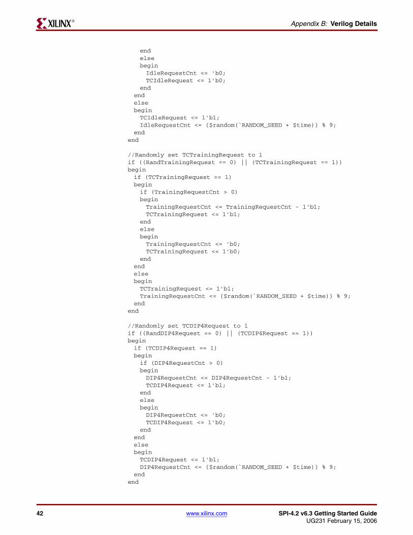
42 www.xilinx.com SPI-4.2 v6.3 Getting Started GuideUG231 February 15, 2006
Appendix B: Verilog DetailsR
endelsebeginIdleRequestCnt <= 'b0;TCIdleRequest <= 1'b0;
endendelsebeginTCIdleRequest <= 1'b1;IdleRequestCnt <= {$random(`RANDOM_SEED + $time)} % 9;
endend
//Randomly set TCTrainingRequest to 1if ((RandTrainingRequest == 0) || (TCTrainingRequest == 1))beginif (TCTrainingRequest == 1)beginif (TrainingRequestCnt > 0)beginTrainingRequestCnt <= TrainingRequestCnt - 1'b1;TCTrainingRequest <= 1'b1;
endelsebeginTrainingRequestCnt <= 'b0;TCTrainingRequest <= 1'b0;
endendelsebeginTCTrainingRequest <= 1'b1;TrainingRequestCnt <= {$random(`RANDOM_SEED + $time)} % 9;
endend
//Randomly set TCDIP4Request to 1if ((RandDIP4Request == 0) || (TCDIP4Request == 1))beginif (TCDIP4Request == 1)beginif (DIP4RequestCnt > 0)beginDIP4RequestCnt <= DIP4RequestCnt - 1'b1;TCDIP4Request <= 1'b1;
endelsebeginDIP4RequestCnt <= 'b0;TCDIP4Request <= 1'b0;
endendelsebeginTCDIP4Request <= 1'b1;DIP4RequestCnt <= {$random(`RANDOM_SEED + $time)} % 9;
endend

SPI-4.2 v6.3 Getting Started Guide www.xilinx.com 43UG231 February 15, 2006
Random Testcase Sample CodeR
//Randomly set TCDIP2Request to 1if ((RandDIP2Request == 0) || (TCDIP2Request == 1))beginif (TCDIP2Request == 1)beginif (DIP2RequestCnt > 0)beginDIP2RequestCnt <= DIP2RequestCnt - 1'b1;TCDIP2Request <= 1'b1;
endelsebeginDIP2RequestCnt <= 'b0;TCDIP2Request <= 1'b0;
endendelsebeginTCDIP2Request <= 1'b1;DIP2RequestCnt <= {$random(`RANDOM_SEED + $time)} % 9;
endend
//Randomly set TCSnkDip2ErrRequest to 1if ((RandSnkDip2ErrRequest == 0) || (TCSnkDip2ErrRequest == 1))beginif (TCSnkDip2ErrRequest == 1)beginif (SnkDip2ErrRequestCnt > 0)beginSnkDip2ErrRequestCnt <= SnkDip2ErrRequestCnt - 1'b1;TCSnkDip2ErrRequest <= 1'b1;
endelsebeginSnkDip2ErrRequestCnt <= 'b0;TCSnkDip2ErrRequest <= 1'b0;
endendelsebeginTCSnkDip2ErrRequest <= 1'b1;SnkDip2ErrRequestCnt <= {$random(`RANDOM_SEED + $time)} % 9;
endend
//Sends a random sized packet to a random channelif (RandTask == 0)begintasks.send_packet({$random(`RANDOM_SEED + $time)} % (`NUM_CHANNELS
- 1), ($random(`RANDOM_SEED + $time) % 255) + 1'b1);end//Sends a random sized packet to a random channel. Also SOP, EOP, and//Err are randomizedelse if (RandTask == 1)begintasks.send_user_data({$random(`RANDOM_SEED + $time)} % 2,
{$random(`RANDOM_SEED + $time + $random(`RANDOM_SEED))} % 2,

44 www.xilinx.com SPI-4.2 v6.3 Getting Started GuideUG231 February 15, 2006
Appendix B: Verilog DetailsR
{$random(`RANDOM_SEED + $time + $random(`RANDOM_SEED + $time))} % 2, {$random(`RANDOM_SEED + $time)} % (`NUM_CHANNELS - 1), ($random(`RANDOM_SEED + $time) % 255) + 1'b1);end//Sends a random number of idles to the Sink Coreelse if (RandTask == 2)begintasks.send_idles(({$random(`RANDOM_SEED + $time)} % 10) + 1);
end//Sends a random number of training patterns to the sink coreelse if (RandTask == 3)begintasks.send_training(({$random(`RANDOM_SEED + $time)} % 10) + 1);
endelsebegin@ (posedge RDClk2x);$display("Out of Range: %0d", $time);
endend

SPI-4.2 v6.3 Getting Started Guide www.xilinx.com 45UG231 February 15, 2006
R
Appendix C
SPI-4.2 File Descriptions
This appendix lists the files generated by the Xilinx CORE Generator system.
Name Description
CORE Generator Project Files (<proj_dir>)
<component_name>_pl4_snk_top.edf* Sink core netlist
<component_name>_pl4_src_top.edf* Source core netlist
<component_name>_pl4_snk_top.v[hd] Sink core functional VHDL or Verilog simulation model (UniSim base)
<component_name>_pl4_src_top.v[hd] Source core functional VHDL or Verilog simulation model (UniSim base)
<component_name>_pl4_snk_top.v{ho | eo} Sink core VHDL or Verilog instantiation template
<component_name>_pl4_src_top.{ho | eo} Source core VHDL or Verilog instantiation template
<component_name>.xco CORE Generator project specific option file
<component_name>_flist.txt
Release Notes (<proj_dir>/<component_name>)
spi4_2_release_notes.txt SPI-4.2 v6.3.2 Release Notes in a text file
Documentation (<proj_dir>/<component_name>/doc)
spi4_2_ds209.pdf SPI-4.2 Core Data Sheet in a PDF file
spi4_2_gsg231.pdf SPI-4.2 Getting Started Guide in a PDF file
Example Design Files (<proj_dir>/<component_name>/example_design)
<component_name>_top.ucf* SPI-4.2 Core wrapper design example constraints file
<component_name>_top.v[hd]* Core VHDL or Verilog top level wrapper file
<component_name>_snk_top.ncf Sink core constraints (NCF) file
<component_name>_src_top.ncf Source core constraints (NCF) file
[<component_name>_snk_top.v] Verilog component declaration for the Sink core
[<component_name>_src_top.v] Verilog component declaration for the Source core
pl4_fifo_loopback.v[hd] FIFO Loopback VHDL or Verilog Top-level File
pl4_fifo_loopback_read.v[hd] FIFO Loopback VHDL or Verilog Read Module
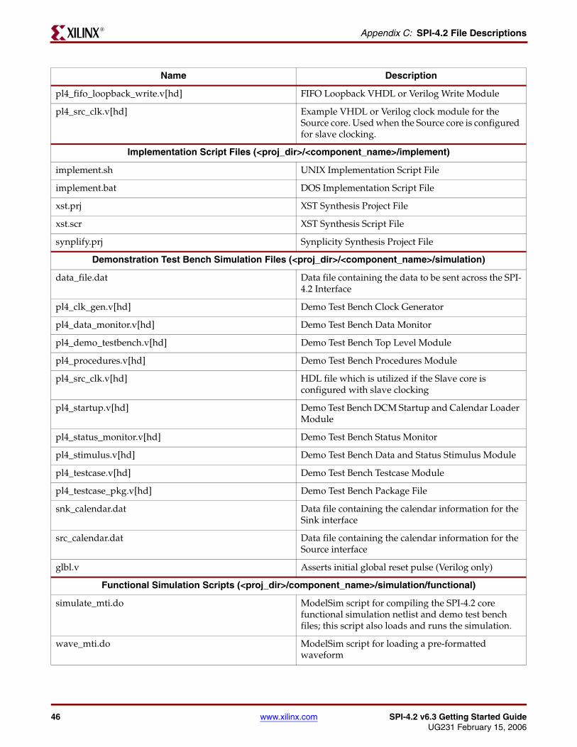
46 www.xilinx.com SPI-4.2 v6.3 Getting Started GuideUG231 February 15, 2006
Appendix C: SPI-4.2 File DescriptionsR
pl4_fifo_loopback_write.v[hd] FIFO Loopback VHDL or Verilog Write Module
pl4_src_clk.v[hd] Example VHDL or Verilog clock module for the Source core. Used when the Source core is configured for slave clocking.
Implementation Script Files (<proj_dir>/<component_name>/implement)
implement.sh UNIX Implementation Script File
implement.bat DOS Implementation Script File
xst.prj XST Synthesis Project File
xst.scr XST Synthesis Script File
synplify.prj Synplicity Synthesis Project File
Demonstration Test Bench Simulation Files (<proj_dir>/<component_name>/simulation)
data_file.dat Data file containing the data to be sent across the SPI-4.2 Interface
pl4_clk_gen.v[hd] Demo Test Bench Clock Generator
pl4_data_monitor.v[hd] Demo Test Bench Data Monitor
pl4_demo_testbench.v[hd] Demo Test Bench Top Level Module
pl4_procedures.v[hd] Demo Test Bench Procedures Module
pl4_src_clk.v[hd] HDL file which is utilized if the Slave core is configured with slave clocking
pl4_startup.v[hd] Demo Test Bench DCM Startup and Calendar Loader Module
pl4_status_monitor.v[hd] Demo Test Bench Status Monitor
pl4_stimulus.v[hd] Demo Test Bench Data and Status Stimulus Module
pl4_testcase.v[hd] Demo Test Bench Testcase Module
pl4_testcase_pkg.v[hd] Demo Test Bench Package File
snk_calendar.dat Data file containing the calendar information for the Sink interface
src_calendar.dat Data file containing the calendar information for the Source interface
glbl.v Asserts initial global reset pulse (Verilog only)
Functional Simulation Scripts (<proj_dir>/component_name>/simulation/functional)
simulate_mti.do ModelSim script for compiling the SPI-4.2 core functional simulation netlist and demo test bench files; this script also loads and runs the simulation.
wave_mti.do ModelSim script for loading a pre-formatted waveform
Name Description

SPI-4.2 v6.3 Getting Started Guide www.xilinx.com 47UG231 February 15, 2006
R
Timing Simulation Scripts (<proj_dir>/component_name>/simulation/timing)
simulate_mti.do ModelSim script for compiling the SPI-4.2 core back-annotated timing netlist and demo test bench files; this script also loads and runs the simulation.
wave_mti.do ModelSim script for loading a pre-formatted waveform
*File is required for implementation.
Name Description

48 www.xilinx.com SPI-4.2 v6.3 Getting Started GuideUG231 February 15, 2006
Appendix C: SPI-4.2 File DescriptionsR

SPI-4.2 v6.3 Getting Started Guide www.xilinx.com 49UG231 February 15, 2006
R
Appendix D
Data and Status Monitor Warnings
The Data and Status monitors continuously check data sent to and received from the demonstration test bench. There are several common warnings that occur when the Testcase module is modified. The warnings are listed and described below.
TDat Warning. Source is segmenting packets <simulation time>
This warning means that the Source core is sending payload resumes in the middle of sending a burst. This is acceptable operation if SrcBurstMode = 0. If SrcBurstMode = 1, this should only occur if the maximum burst length is reached (as defined by SrcBurstLen).
RStat Info. Sink is out of frame. Expect TDat mismatches <simulation time>
This indicates that the Sink core went out of frame during operation. Unless training or idles are being sent on RDat when this occurs, there will be data errors on TDat. This is because what is being sent in on RDat is no longer being transferred to TDat.
RStat Info. Expected DIP2 mismatch received: SnkDip2ErrReqFlag = 1 <simulation time>
This indicates that a DIP2 error was detected on RStat. It is only a note and not an error because SnkDip2ErrReq was asserted, which means that a DIP2 error is expected.
RDat Warning. Protocol Violation #4. Idle follows data on a non-credit boundary <simulation time>
This indicates that the SPI-4.2 protocol was violated when data was sent from the demonstration test bench. The most likely cause is that send_user_data was used to send data without an EOPS, which ended on a non-credit boundary, then an idle was sent using send_idles.
RDat Warning. Protocol Violation
Any RDat protocol violation occurred because of incorrectly formatted data transmitted from the Testcase Module (that is, they are user-created).

50 www.xilinx.com SPI-4.2 v6.3 Getting Started GuideUG231 February 15, 2006
Appendix D: Data and Status Monitor WarningsR