Logical Systems and Knowledge Representation Fuzzy Logical Systems 1.

Logical and Physical Design Issues for SmartCard Databases
CRISTIANA BOLCHINI, FABIO SALICE, FABIO A. SCHREIBER, andLETIZIA TANCAPolitecnico di Milano
The design of very small databases for smart cards and for portable embedded systems is deeplyconstrained by the peculiar features of the physical medium. We propose a joint approach to thelogical and physical database design phases and evaluate several data structures with respect tothe performance, power consumption, and endurance parameters of read/program operations onthe Flash-EEPROM storage medium.
Categories and Subject Descriptors: H.2.1 [Database Management]: Logical Design; H.2.2[Database Management]: Physical Design—Access methods
General Terms: Design, Performance
Additional Key Words and Phrases: Design methodology, access methods, data structures, flashmemory, personal information systems, smart card
1. INTRODUCTION
The Information Management area is currently seeing the growth, in numberas well as in size, of applications that can profit from modern portable devicessuch as palm computers, cell phones, and smart cards.
While smart cards have been recognized as being among today’s most secureportable computing devices [ItGov 2002; Sun Microsystems 1999; DataQuest1998; Bobineau et al. 2000], almost no attention has been devoted to the mostappropriate ways of adapting database techniques to this most powerful tool.Bobineau et al. [2000] made a very thorough examination of the relevant issuesthat arise in this context, by proposing a storage model complete with querycost evaluation, plus transaction techniques for atomicity and durability in thisparticular environment. To our knowledge, this is the most complete attempt toanalyze in-depth database management system (DBMS) design problems withrespect to microdevices.
The attention of Bobineau et al. [2000] was mostly devoted to DBMS de-sign techniques, following the traditional assumption that data structures and
Authors’ address: Politecnico di Milano, Dip. Elettronica e Informazione, P.zza L. da Vinci, 32,20133 Milan, Italy; email: {bolchini,salice,schreibe,tanca}@elet.polimi.it.Permission to make digital/hard copy of part or all of this work for personal or classroom use isgranted without fee provided that the copies are not made or distributed for profit or commercialadvantage, the copyright notice, the title of the publication, and its date appear, and notice is giventhat copying is by permission of ACM, Inc. To copy otherwise, to republish, to post on servers, or toredistribute to lists requires prior specific permission and/or a fee.C© 2003 ACM 1046-8188/03/0700-0254 $5.00
ACM Transactions on Information Systems, Vol. 21, No. 3, July 2003, Pages 254–285.

Design Issues for Smart Card Databases • 255
access methods should be designed once and for all by the DBMS manufac-turer while the database designer should be in charge of conceptual and logicaldatabase design, confining the physical design phase to the mere choice of fieldsto be indexed. By contrast, we claim that, besides the typical interface for tabledefinition and indexing, the data definition language (DDL) of a smart cardDBMS should expose also the handles for a number of data structures (withthe corresponding algorithms), ready to be chosen by the smart card databasedesigner, appropriately assisted by system support. Indeed, owing to the in-trinsic limitations of the smart card medium, the database designer shouldbe aware of the physical constraints from the very beginning of the designprocess; there are two main design phases where these constraints are to beenforced:
—The classical information system lifecycle contemplates, at conceptual de-sign time, a view design and integration phase where data and proceduresbelonging to information system areas are first singled out and then appro-priately integrated. When the system is distributed, at logical design timetables are partitioned among the system sites according to appropriate frag-mentation and replication criteria. In a similar way, in our context, such dataand procedures must be accommodated on the smart card itself, and appro-priately distributed and replicated on other fixed sites the smart card mightbe connected to.
—At logical/physical design time, the threefold objective of performance, powerconsumption and memory endurance optimization must influence the eval-uation of on-card data structures and algorithms, and the policy of data ma-nipulation (e.g., delete operations). An accurate study of this phase allowsthe smart card database designer, appropriately supported by our tool, tospecify to the DBMS which of these data structures and algorithms shouldbe used for table access.
Note that power management is also an issue in this scenery, since sometimesthe smart card terminal is not directly connected to a power source, for example,in case of subscriber information module (SIM) cards for cellular phones.
Moreover, some applications can involve sensible personal data that requirea variable level of privacy. Since privacy aspects have a great importance in auniform storage medium with tightly packed sensitive information, their im-pact should be considered as early as possible in the design phase [Bolchini andSchreiber 2002].
The purpose of our research was to conceive a full-fledged database designmethodology, which should guide the database designer from the conceptualdesign step, carried out in the traditional way by using one of the well-knownconceptual design models, to the semiautomatic choice of the data structures,access methods, and memory allocation/management policies, based on theanalysis of the physical storage devices currently offered by smart card tech-nology. To this aim, we propose a logical-physical data model, that is, a numberof structures and algorithms the smart card DBMS should implement and offerto the choice of the system-assisted database designer.
ACM Transactions on Information Systems, Vol. 21, No. 3, July 2003.

256 • Bolchini et al.
Since the real restrictions of today’s smart cards concern much more sec-ondary storage capacity than the computational power of their instruction sets,rather than studying possible reductions to SQL (as the standard ISO/IEC7816-7 does, introducing Structured Card Query Language (SCQL) [Rankl andEwffing 1999], a subset of SQL for smart cards), we concentrate on the best dataorganization policies for secondary memory, in order to implement a full-fledgedquery language.
In this paper we introduce the design methodology, and then concentrate onthe logical-physical data model that supports the design of such novel databaseapplications.
The paper is organized as follows: after the introduction of a running ex-ample that will be used throughout the paper, Section 2 outlines the proposedmethodology and singles out the specific topic addressed by this paper, that is,the guidelines for semiautomatic design of data structures and access methodsfor smart card data. Section 3 presents the reader with a brief on the most re-cent technological issues related with our problem, namely, smart card storagedevices. Section 4 introduces the data structures we propose for the physicalstorage of on-card tables, together with the annotations the designer is requiredto specify in order for the system to provide physical design support. Sections 5and 6 examine the issue from the DBMS viewpoint, that is, they study thecost of the various access operations as well as the most suitable physical im-plementation policies, which are strongly related to the technological featuresof smart card memory support. The discussion is supported by simulation re-sults in Section 7. Future developments and research trends are discussed inSection 8, along with the final conclusions.
2. A SMART CARD DATABASE DESIGN METHODOLOGY
In this section, after a short discussion on possible categories of smart carddatabases, we introduce our running example and briefly outline the generalmethodology for smart card database design. The next sections are devotedto the details of those methodology steps that are the subject matter of thispaper.
In our view, smart card databases can be classified into two main categories:
(a) Single-application databases (SADs), where only one application ismodeled: examples of this category are personal financial databases as thestock portfolio, or a personal travel database, recording all the travel infor-mation considered interesting by the smart card owner; the PIA (portableinternet access database), reported in the sequel as a running example,belongs to this category.
(b) Personal (micro) information systems (PISs), whose most noticeable exam-ple is the citizen’s card, recording such administrative personal data asdriver’s licence and car information, passport, judicial registry, etc.; anotherexample of this category is the medical record, reporting the owner’s clinicalhistory complete with all the past clinical tests and diagnoses [Sutherlandand Van Den Heuvel 2002].
ACM Transactions on Information Systems, Vol. 21, No. 3, July 2003.
Design Issues for Smart Card Databases • 257
A noticeable feature of smart card databases is that the owner and all his/herinformation have a peculiar role in the entity-relationship (ER) schema; infact, while items of the card owner’s data constitute the virtual center of thedatabase, they often amount to a unique entry, that is, a singleton record. Thisrole could be compared to that of the home page of a Web site, which is justa singleton entity in the site schema, or to the fact table of a relational on-line analytical processing (OLAP) schema for a data warehouse [Atzeni et al.2000].
This point is much less relevant for SADs than for PISs, where the futureapplications of smart cards will see the integration of more than one personalapplication, all conceptually related to one another by means of such a databasecenter. The design of this category of smart card databases presents many simi-larities to that of distributed applications, for the relevant information must bedistributed among the smart card and other fixed devices the smart card willbe connected to: imagine the road police department recording all the driver’slicense and car data, a portion of which is also recorded and appropriatelyupdated on-card, while the court of justice records contains all the possiblelegal charges against the owner. Notice that this consideration has driven usto proposing, for our methodology, some initial steps that mimic very closelydistributed database design.
Now we introduce our running example: a portable database used to storepersonal information related to Internet navigation.
2.1 The Portable Internet Access Database
As an example of a single-application database, let us consider the case of asmart card for Internet access data, storing personal information related to auser’s Internet navigation history. Here the key idea is to store information con-cerning favorite Web sites (bookmarks), {login, password} pairs used to accessprotected areas of the Web, a log of the most recently accessed unified resourcelocator (URLs), and, finally, an electronic purse (e-purse) to directly managepayments, with a log of the most recent ones; note that e-purses might be mul-tiple, as in the case of several credit cards (for instance, a corporate one forcompany expenses and a personal card for one’s own use).
All this information is meant to be available on the smart card, possiblyprotected by encryption in order to guarantee information privacy: the cardowner will sit in front of a generic Internet-connected machine, and find his/herInternet environment ready for use.
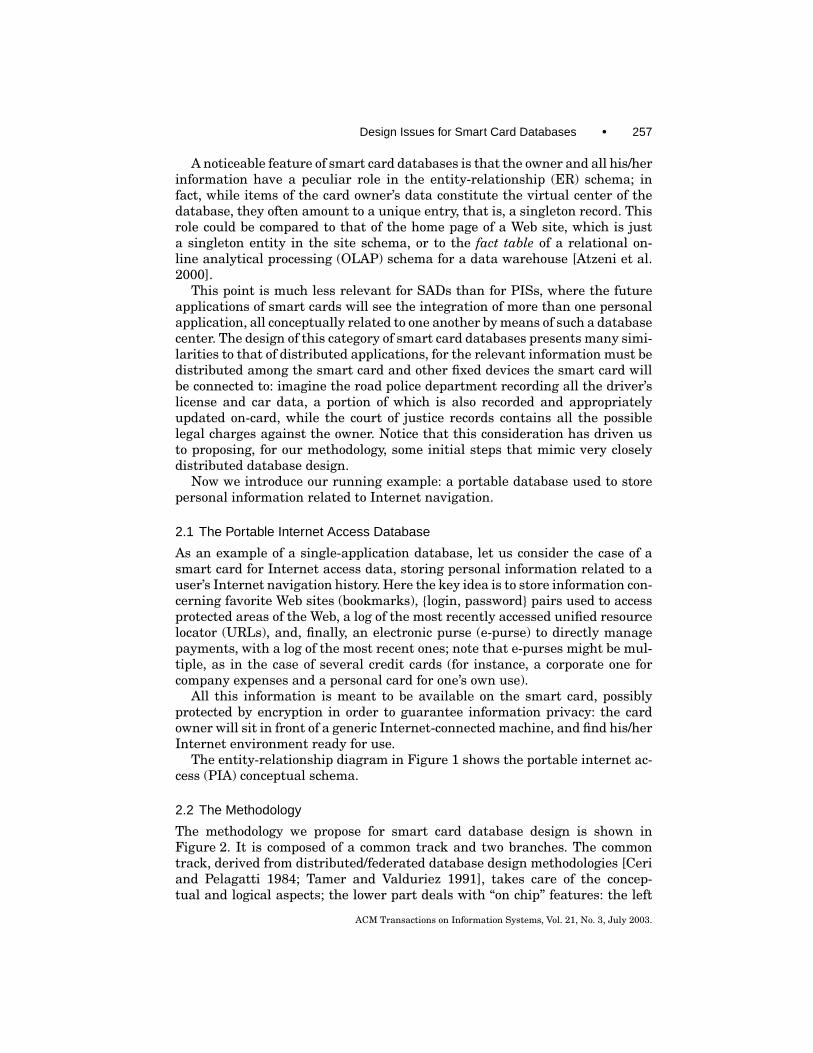
The entity-relationship diagram in Figure 1 shows the portable internet ac-cess (PIA) conceptual schema.
2.2 The Methodology
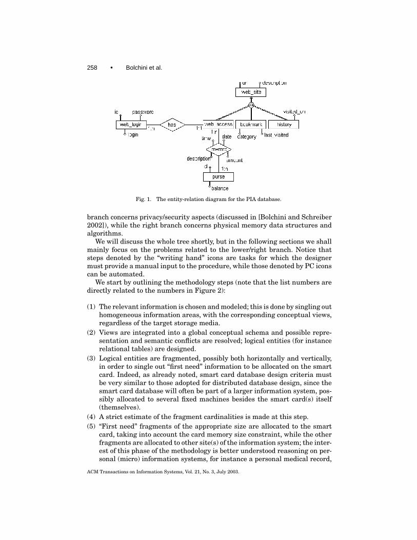
The methodology we propose for smart card database design is shown inFigure 2. It is composed of a common track and two branches. The commontrack, derived from distributed/federated database design methodologies [Ceriand Pelagatti 1984; Tamer and Valduriez 1991], takes care of the concep-tual and logical aspects; the lower part deals with “on chip” features: the left
ACM Transactions on Information Systems, Vol. 21, No. 3, July 2003.
258 • Bolchini et al.
Fig. 1. The entity-relation diagram for the PIA database.
branch concerns privacy/security aspects (discussed in [Bolchini and Schreiber2002]), while the right branch concerns physical memory data structures andalgorithms.
We will discuss the whole tree shortly, but in the following sections we shallmainly focus on the problems related to the lower/right branch. Notice thatsteps denoted by the “writing hand” icons are tasks for which the designermust provide a manual input to the procedure, while those denoted by PC iconscan be automated.
We start by outlining the methodology steps (note that the list numbers aredirectly related to the numbers in Figure 2):
(1) The relevant information is chosen and modeled; this is done by singling outhomogeneous information areas, with the corresponding conceptual views,regardless of the target storage media.
(2) Views are integrated into a global conceptual schema and possible repre-sentation and semantic conflicts are resolved; logical entities (for instancerelational tables) are designed.
(3) Logical entities are fragmented, possibly both horizontally and vertically,in order to single out “first need” information to be allocated on the smartcard. Indeed, as already noted, smart card database design criteria mustbe very similar to those adopted for distributed database design, since thesmart card database will often be part of a larger information system, pos-sibly allocated to several fixed machines besides the smart card(s) itself(themselves).
(4) A strict estimate of the fragment cardinalities is made at this step.(5) “First need” fragments of the appropriate size are allocated to the smart
card, taking into account the card memory size constraint, while the otherfragments are allocated to other site(s) of the information system; the inter-est of this phase of the methodology is better understood reasoning on per-sonal (micro) information systems, for instance a personal medical record,
ACM Transactions on Information Systems, Vol. 21, No. 3, July 2003.
Design Issues for Smart Card Databases • 259
Fig. 2. The entire methodology.
where the most recent clinical tests are kept on card, while the whole per-sonal clinical record is stored in the family physician’s computer.
At this point a first comparison is to be made between the fragments andthe smart card storage capacity: possibly fragmentation and allocation criteriashall be reconsidered.
(6) (a) Access rights are defined for each fragment and for each user class,and the relevant constraints are included in the view definitions: for in-stance, in the case of a car accident, the first aid personnel of an ambulanceshould read from the medical card the patient’s blood pressure record, butnot his/her possible insurance policies (to be used later by the hospital ad-ministration); with respect to the personal legal information card, the traf-fic authorities should have a read-only access to the relevant informationof the judicial registry connected to the individual’s license [Bolchini andSchreiber 2002]; (b) the type of access mode (read only, read/write) and the
ACM Transactions on Information Systems, Vol. 21, No. 3, July 2003.

260 • Bolchini et al.
volatility (for example in terms of update/query ratio) are estimated foreach fragment (see Sections 4 to 6 later in this paper).
(7) (a) Memory protection mechanisms are to be designed in order to preventunauthorised users to access sensitive information; (b) the most convenientdata structures are chosen (see Sections 4 to 6).
(8) (a) Possibly an encryption algorithm is chosen for some very sensitive data;(b) access methods are chosen for the data structures defined at step 7(b)under the constraints coming from step 7(a) (see Sections 4 to 6).
At step 6(b) the information is gathered in order to allocate the same type ofinformation, in terms of volume and volatility, on the same sets of blocks. In par-ticular, if asymmetric Flash-EEPROM (EEPROM = electrically erasable pro-grammable read-only memory) is considered (for more details see Section 3.2),where four different block sizes are normally used, very low-volume informationcan be stored in the smallest blocks while high-volume information can be storedin one or more of the biggest blocks. At steps 7(b) and 8(b), the methodology issupported by a tool for the choice of the appropriate physical data structuresand access algorithms among those offered by the smart card DBMS, as shownin Sections 4 to 6.
3. SMART CARD TECHNOLOGY ISSUES
Smart cards are essentially devices that allow information storage and process-ing, but need to interact with an active device providing the necessary powersupply. Based on the technology adopted for the memory device and for the on-card processing unit, different types of smart cards can be chosen, according tothe required security level.
The simplest architecture is the processor card, which contains a micropro-cessor, a simple cryptographic coprocessor, and blocks of memory includingrandom access memory (RAM), read-only memory (ROM), and a nonvolatilememory (usually EEPROM or Flash-EEPROM). More sophisticated cards, cryp-tographically enabled, are based on the processor card architecture where thesimple cryptographic coprocessor is replaced by an advanced one. The improve-ment in the crypto cards allows public key encryption, whereas processor cardsonly provide private key encryption. Given the application environment this pa-per presents, the target architecture is the microprocessor multifunction card(MMC).
3.1 Microprocessor Multifunction Cards
The microcontroller used in Smart card applications contains a central pro-cessing unit (CPU) and blocks of memory, including RAM, ROM, and repro-grammable nonvolatile memory (NVM). RAM is used to store executing pro-grams and data temporarily, while ROM is used to store the operating system(Card Operating System, or COS), fixed data, standard routines, and lookuptables. The reprogrammable nonvolatile memory is used to store informationthat has to be retained when power is removed, but that must also be alter-able to accommodate data specific to individual cards or any changes possible
ACM Transactions on Information Systems, Vol. 21, No. 3, July 2003.

Design Issues for Smart Card Databases • 261
Fig. 3. A schematic representation of a smart card microcontroller.
Table I. Smart Card MicrocontrollerCharacteristics (December 2002)
Component CharacteristicsCPU 8-16-32 bitsRAM 256 bytes to 1 kbytesROM up to 32 kbytesEEPROM 256 bytes to 64 kbyteswrite/erase cycles minimum 100,000 cycles
over their lifetimes; more specifically, the smartcard NVM constitutes the datastorage for the database. Based on this consideration, technology issues have asignificant impact on the overall system performance.
Components of this type of architecture include a CPU, RAM, ROM, andEEPROM. The operating system is typically stored in ROM, the CPU usesRAM as its working memory, and most of the data is stored in EEPROM. A ruleof thumb for smart card silicon is that RAM requires four times as much spaceas EEPROM, which in turn requires four times as much space as ROM. Typicalconventional smart card architectures (Figure 3) have properties as shown inthe following Table I.
A preliminary analysis concerns a comparison of the features and perfor-mance of the two main NVM architectures, in order to focus our analysis on aspecific memory type. In fact, although classical EEPROM (from now on calledsimply EEPROMs) and Flash-EEPROM (from now on called simply Flash) arefunctionally equivalent (both are electrically erasable reprogrammable non-volatile memory), they differ in terms of performance, integration density, cost,read/program/erase methods. The comparison we summarize later in this paperseems to be to the advantage of Flash memories as more promising for futureMMC. Furthermore, the size reduction of the transistor used to implementmemories makes it increasingly difficult to scale EEPROMs since this tech-nology requires relatively high voltage (18 V) to be applied during the writeprocess; thus, EEPROMs will not be suitable for high-density product genera-tion beyond 0.18 µm [Stockdill 2002].
ACM Transactions on Information Systems, Vol. 21, No. 3, July 2003.

262 • Bolchini et al.
In EEPROMs, the contents may be erased and programmed at byte level,typically 16, 32, or 64 bytes. The erase operation is transparent to the user;read time is approximately 150 ns, program time is 10 ms/16, 32, or 64 bytepage (157–625 µs/byte) while erase time is not applicable.
In Flash memories write data operations are programming operations thatcan only be performed if the target location has never been written before,or has been previously erased. A further complication and space/performancecost arise from the fact the erase operation works only on blocks of data ata time. Flash memories are divided into blocks, and each block can be erasedseparately; read and program operations work independently of the blocks; anybyte (word) can be read or programmed separately.
Thus, in Flash memories the minimum erase element is larger than theminimum read/program element; the erase element is a page, sector, or theentire device, while the read/program element is a byte or a word; read time isapproximately 80 ns at 5 V (or 120 ns at 3 V), program time is 10 µs/byte at 5 V(17 µs/byte at 3 V) and the erase operation requires approximately 0.45 s/8-kBblock at 5 V (0.5 s/8-kB block at 3 V). As for integration density, Flash memoriesare more compact than EEPROMs; in particular, Flash is approximately twotimes more compact than EEPROM [Stockdill 2002].
Summarizing, although Flash memories are more interesting than EEP-ROMs in terms of read/write time and integration density, they present a dis-advantage concerning the erase operation that is particularly expensive withrespect to time and power consumption. However, these drawbacks can bestrongly reduced if a correct erase policy is applied. For example, if a blockis erased only when its entire content has to be modified, an EEPROM memoryis approximately four times slower than a Flash one in writing 64k bytes in thesame single block for n times. Although this example represents a special case,an appropriate set of policies can make Flash memories much more interestingthan EEPROMs.
As a consequence, in what follows we concentrate on the peculiar character-istics of Flash memories, in order to target the previously presented analysis toaccess times, costs, and architectural characteristics to this specific technology.
In Butler et al. [2001], the authors explored the problems related to EEPROMstorage optimization for smart cards and introduced the “transacted memory”technology which embeds transaction capabilities in the memory itself, whilemanaging data information and EEPROM space. The main assumption, whichinfluences and motivates the approach proposed by the authors, is that EEP-ROM technology allows only block writes. Given this premise, the transactedmemory manager provides tags and additional components to optimize storageuse and transaction features. In the technological environment we consider,there is not such a restriction to write on a per block basis; thus our approachhas different requirements and constraints. Nevertheless, as we will discuss inwhat follows, we also adopt a tagging technique in order to optimize storageuse and to achieve a long EEPROM lifetime.
We must also notice that the peculiar features of Flash memories makesmart card databases differ from main memory databases (MMDBs). In fact,Eich [1992] noted: “In a Main Memory Database system . . . the need for I/O
ACM Transactions on Information Systems, Vol. 21, No. 3, July 2003.

Design Issues for Smart Card Databases • 263
Table II. EEPROM and Flash-EEPROM Technical Characteristics (December 2002)
EEPROM Flash-EEPROMRead (nsec) 150 80@5V to 120@3VProgram (µsec/byte) 157 (64 Byte) to 625 (16 Byte) 10@5V to 17@3VErase (sec/block) N.A. 0.45@5V to 0.5@3VCell Components 2 transistors 1 transistorCell Size (µm2 @ 0.4 µm tech) 4,2 2Cost per bit Medium LowEndurance (write/erase cycles) 10k to 100k write cycle/byte 10k to 100k erase cycle/block
operations to perform database applications is eliminated . . .” (p. 507); this as-sertion is due to the substantial homogeneity of the RAM storage medium forMMDBs [Garcia-Molina and Salem 1992]. Moreover a great part of main mem-ory database studies are devoted to overcoming the RAM volatility proper-ties. This is not the case for a smart card database system where Flash mem-ory acts as a true secondary storage with very different read/write propertieswith respect to the RAM main memory, making it look more like a traditionalDBMS.
3.2 Flash Memories: Dimension, Power and Timing Issues
So far, the amount of data storage available in a Flash memory ranges form32 Mbit to 512 Mbit (both organized by 8 or 16). Research for 512 Mbit andabove is currently taking place. Power requirements vary depending on theoperation that has to be performed. A read operation requires an average ofabout 10 mA (12 mA max) whereas program and erase operations require anaverage of about 20 mA (35 mA max).
Access time depends on both the operations and the mode. To enlarge onwhat we introduced in Section 3.1, as far as read access is concerned, randomread requires about 150 ns (for example, 100 ns in NOR Flash architecture(Intel, AMD) and 120 ns in DINOR Flash architecture (Mitsubishi)), whereasread page mode and read burst mode (when supported by the memory) requiresabout 35 µs to access the first byte in a page and 50 ns for subsequent reads(for example, 25 µs first byte and 50 ns subsequent bytes in NAND Flash ar-chitecture (Toshiba) and 50 µs first byte and 50 ns subsequent bytes in ANDFlash architecture (Hitachi)). Concerning programming time, each program op-eration takes approximately an average of 13 µs per byte or word. Erase timedepends on block dimension: typically a 64-kbyte block takes about 0.7 s. An-other consideration concerns Flash endurance: in fact, a Flash memory worksfor 100,000 erase cycles/block. This data is all reported in Table II.
In order to achieve good performance and a long endurance, it is thus neces-sary to reduce the number of data modifications. Since update, delete, and insertoperations are required and inevitable, the remainder of the paper focuses onstorage and management techniques that minimize the cost associated withthe required operations.
It is worth noting that the time to erase a block is approximately 10 timesthat required to program a block, which, in turn, is 100 times that required
ACM Transactions on Information Systems, Vol. 21, No. 3, July 2003.

264 • Bolchini et al.
to read a block; as a consequence, our effort is to reduce the number of eraseoperations.
4. DATA STRUCTURES AND ANNOTATIONS: THE LOGICAL-TO-PHYSICALDATA MODEL
Given the main applications we envisage for smart card databases, and in gen-eral for embedded systems based on a Flash memory permanent storage, weassume that the volumes of data which must be readily available will not needto be not very huge: data fragmentation and allocation will lead to a reductionof the cardinality of the relations actually stored on the smart card. For exam-ple, even if we imagine that the PIA will store all the user’s visited sites, mostprobably only the last 30 sites will be kept on card, while the rest will consti-tute a fragment allocated in the card owner’s personal computer. Thus we claimthat the data types adopted for physical storage must be very simple, appropri-ately used in relation to the data volume and usage type of each specific dataclass.
In order to illustrate this part of the methodology, we rely of the PIA databaseexample, introduced in Section 2: this very simple example will be useful forthis paper’s purposes, where the relevant issue is more related to logical andphysical considerations than to the (equally interesting) subject of fragmenta-tion and allocation criteria.
From now on, to fix ideas and without loss of generality, we shall refer to therelational model of data [Atzeni et al. 2000], also because this model affordsa high degree of simplicity consistent with the dimensional requirements ofthe device. However, our considerations can be extended to other logical modelswithout much effort. We consider the logical schema of the PIA database shownin Figure 1 (primary keys are underlined):
TBL BOOKMARKS (URL,DESCRIPTION,CATEGORY, LAST VISITED)TBL HISTORY (URL, DESCRIPTION, VISITED ON)TBL WEBLOGIN (ID, LOGIN, PASSWORD)TBL ACCESS (URL, DESCRIPTION, LOGIN ID)TBL MOVEMENTS (PURSE ID, DATE, TIME, URL, DESCRIPTION, AMOUNT)TBL PURSE (ID, BALANCE)
In order to model the relations to be stored and managed by the database,four data types have been identified1:
—Heap relation, characterized by a limited cardinality, generally less than 10records, used to store a few records, unsorted, typically accessed by scan-ning all records when looking for a specific one. In the running example, thelogin/password pairs relation fits these characteristics.
—Sorted relation, characterized by medium cardinality (∼100 to ∼1000records) and by being sorted with respect to a field. This kind of relationis used to store information typically accessed by the order key. Dependingon the size of the relation, it will be possible to store the entire relation on
1The terms are partially taken from file classification.
ACM Transactions on Information Systems, Vol. 21, No. 3, July 2003.
Design Issues for Smart Card Databases • 265
card, or eventually only a subset of the records; once the upper bound isreached, the user will have to delete a record before adding a new one. Withrespect to the running example, URL bookmarks can be managed by meansof sorted data.
—Circular list relation, still characterized by the same cardinality of the previ-ous data type, but stored and managed as a circular list, typically sorted bydate/time. This kind of relation is typically suitable to manage a fixed num-ber of log data; once the maximum number of records is reached, the nextnew record will substitute the oldest one. In the PIA example, data logs ofthe last m URLs most recently visited and the last n payments in the e-pursecan be stored by means of circular lists.
—Generic relation (multiindex structure), not belonging to the previously de-fined categories. Such data might be indexed with respect to more than onefield, by means of some of the data structures suggested in Bobineau et al.[2000] (for instance the ring index approach detailed later in this paper). Thisis the only data structure we propose which resembles the data structuresused in classical DBMSs; however, due to the limited amount of data, webelieve that such data structure will seldom be useful.
4.1 Table Schema Annotation
In this phase the designer feeds the tool with the information needed to choose,for each relation, one of the four data structures just presented.
As a matter of fact, while logical design involves all the parts of the database,on card or allocated on the fixed devices, schema annotation is applied onlyto those relations that will reside on the card. Thus, input of this phase isthe on-card table and fragment definition as produced by steps 4 and 5 of themethodology.
The designer must input, for each on-card relation, the following information:
—number, type, and size (when not determined by the type, e.g., a variablelength character field) of the attributes; such information will provide records’length (in bytes);
—expected relation size, that is, number of records (order of magnitude); and—existence of an upper bound of the number of records during the stable phase
of the database life.
It is then possible to evaluate the amount of permanent memory that will berequired to store the data, without taking into account additional costs due todata management. Such overheads will be estimated in the subsequent stepsof the design methodology.
Now all the relation schemas must be annotated with those aspects thatlead to the selection of the best data type and memory support. The purpose ofthis annotation is to provide estimates of the elements that mainly impact onaccess time and card endurance, in order for the tool to select the most suitablephysical data schema and implementation. For each table, we must know the
ACM Transactions on Information Systems, Vol. 21, No. 3, July 2003.

266 • Bolchini et al.
Fig. 4. Expected operation frequency statements for the initial life of the database for the book-marks relation. The percentages shown on the chart are determined by the input qualitative values.
following:
—Is it a sorted relation (no further indices): yes/no?—Log-like (e.g. sorted on date/time)—Other (specify sort key)
—What is the expected relative frequency of the following operations:—Insert?—Delete?—Update?—Select (sequential scan, equality selection, range selection)?
The designer is expected to give, for each relation, a qualitative compositionof the foreseen workload stating how data access will be distributed among thepossible query types. Note that it is not required to express a precise value;instead what is needed is a percentage of one operation type with respect to theothers. Consider as an example the bookmarks relation in the PIA database.As further discussed later in this paper, we can distinguish two phases in therelation lifetime: an initial time, when the relation is empty and we are build-ing our bookmarks list, and a subsequent phase, when we mainly search thebookmark of the Web site we want to visit.
The designer might thus produce the following two “expected operation fre-quency statements”:
—Initial/startup phase—phase I (Figure 4):—Insert: high frequency;—Delete: low frequency;—Update: low frequency;—Select:
Sequential scan: low frequency;Equality search: medium frequency;Range search: no operation.
—Stable phase—Phase II (Figure 5):—Insert: low frequency;—Delete: low frequency;
ACM Transactions on Information Systems, Vol. 21, No. 3, July 2003.

Design Issues for Smart Card Databases • 267
Fig. 5. Expected operation frequency statements during the stable life of the database for thebookmarks relation. The chart shows the percentages determined by the input qualitative values.
—Update: low frequency;—Select:
Sequential scan: medium frequency;Equality search: high frequency;Range search: no operation.
The designer is expected to enter these parameters as qualitative values:for each operation, whether the operation will never occur (no operation), occurseldom (low frequency), occur moderately (medium frequency), or occur often(high frequency) with respect to the possible operations. It has to be understoodthat the terms low, medium, and high here have only relative significance. Thisinformation is used to foresee the work balance between the types of operations,also characterizing each table’s volatility in order to select the most convenientmemory support, especially since the technological aspects have a relevant im-pact on the smart card performance and life. Such information is required foreach table belonging to the “on-card” relations, and it is provided for the long-term, stable, life of the database.
This annotation step has been carried out on the PIA database, whose anno-tated logical schema is presented in Figure 6.
The next step in the methodology is performed automatically on the basis ofthe gathered information, as described in the following section.
4.2 Physical Design
The tool allocation policy interprets user’s annotations to select one of the avail-able data structures for each one of the database relations. When processingeach relation and its annotations, one of the following situations is met:
(A) limited cardinality relations;(B) ordered date/time field (maximum cardinality constraint);(C) high number of expected records, ordered and with a high volatility (possi-
bly maximum cardinality constraint);(D) none of the above.
ACM Transactions on Information Systems, Vol. 21, No. 3, July 2003.

268 • Bolchini et al.
Fig. 6. The annotated logical schema for the PIA database. The table annotations will be used todetermine, for each relation, the most suitable physical data model.
In the physical data organization step, data structures are selected on thebasis of these four categories:
(A) Limited cardinality relations. When data cardinality is limited (below 10,20), a heap organization is viable even for sorted data, since the overheadof any complex structure maintaining the sorting is not costly, owing to theshort time required for scanning the whole data.
(B) Ordered date/time field (maximum cardinality constraint). The selectionof the circular list data model for relations with a date/time ordering anda maximum cardinality constraint is straightforward.
(C) High number of expected records, ordered and with a high volatility. Re-lations belonging to the third class are physically modeled by means of anordered data structure. It is possible to foresee a particular overhead inmaintaining data sorting during the initial phase of the database, whenmodification operations (i.e., insert, update, delete) prevail with respect toretrieval queries. As a consequence, the implementation of such an ordereddata structure will need to provide a mechanism to efficiently support mod-ification operations, as discussed in Section 6.4.
(D) None of the above. When the relation cannot be referred to any of thediscussed situations, some classical data structure for the implementation
ACM Transactions on Information Systems, Vol. 21, No. 3, July 2003.

Design Issues for Smart Card Databases • 269
of relational tables is adopted, possibly introducing indices when items ofdata are mainly downloaded on the card at programming time and thusproduce mainly query accesses rather than data modifications, as we willsee what follows.
With respect to the PIA example, the applied annotation leads to the follow-ing results:
TBL BOOKMARKS: SORTEDTBL HISTORY: CIRCULAR LISTTBL WEBLOGIN: HEAPTBL ACCESS: SORTEDTBL MOVEMENTS: CIRCULAR LISTTBL PURSE: HEAP
5. ACCESS TYPES, OPERATIONS AND COSTS
In this section, we perform a comparison of the four adopted data types withrespect to the typical foreseen operations to be performed on the data of eachon-card table [Ramakrishnan and Gehrke 2000].
—Scan: fetch all records in the table.—Search with equality selection: fetch all records that satisfy an equality se-
lection, for instance, “find the VisitedURL for day = #05/01/2001#.”—Search with range selection: fetch all records that satisfy a range selection,
such as, for example, “find the movements with amount between $10 and$100.”
—Insert: insert a given record into a table. Depending on how the records arestored, ordered or not, the operation may require a shift of the records follow-ing the position where the new record is inserted, that is, fetch all records,include the new one, and write back all records.
—Delete: search the record(s) and remove it (them) by freeing the space. Moreprecisely, it is necessary to identify the record, fetch the block containing it,modify it, and write the block back. Depending on the record organization,it may be necessary to fetch, modify, and write back all the records followingthe one under consideration.
—Update: search a given record(s), read it (them) and rewrite it (them).
In order to estimate the cost (in terms of access/execution time) of differentdatabase operations:
—let B be the number of data blocks with R records per block, and C theaverage time to process a record (e.g., to compare a field value to a selectionconstant);
—let FRB, FWB, and BE be, respectively, the average time to read, write, anderase a block from/to the Flash memory;
—let FRR and FWR be the average time to read and write a single recordfrom/to the Flash memory, respectively;
ACM Transactions on Information Systems, Vol. 21, No. 3, July 2003.

270 • Bolchini et al.
Table III. Access Timing Costs Estimated for the Three Data Models with Respect to the AccessOperation
Heap data Sorted data Circular dataScan TS H = B×R× (FRR +C) TS S =B×R× (FRR +C) TS C =B×R× (FRR +C)Search
eq.TSEQ H = 1/2 B×R×
(FRR+C)TSEQ S = 2×FRR×
Log2 B+C×Log2 RTSEQ C = 2×FRR×
Log2 B+R×Log2 CSearch
rangeTSR H = B×R× (FRR+
C)+ (FRR+ RWR)×n r
TSR S = TSEQ S+(FRR+RWR)×n r
TSR C = TSEQ C+(FRR+RWR)×n r
Insert TIN H = FRR×R+ C+FWR
TIN S =TSEQ S+ (FRR+FWR+RRR+RWR)×R+C+BE+1/2 B× (FRR+FWR+RRR+ RWR+BE)
TIN C = FRR×R+C+FWR
Delete TDE H = TSEQ H+(FRR+FWR+RRR+RWR)×R+C+BE
TDE S = TIN S TDE C = FRR×R+ C+(FRR+FWR+RRR+RWR)×R+C+BE
Update TUP H = TDE H TUP S = TSEQ S+(FRR+FWR+RRR+RWR)×R+C+BE
TUP C = TDE C
—and finally, for RAM access, let RRR and RWR represent the time to readand write a record in RAM, respectively.
Table III reports the costs for accessing stored data with respect to the dif-ferent organizations. The adopted algorithms exploit the existence of a sortingfield when available, and take into account the Flash technological requirementof allowing the programming only of unwritten elements. As a result, the algo-rithms (and consequently the costs) feature—when necessary—a procedure forsaving data in RAM, erasing an entire Flash block, and restoring from RAMthe part of the block that must be left unchanged. Table III summarizes accesscosts for the first three discussed data models.
As far as heap relations are concerned, there is no specific issue that involvesany of the possible data accesses. Block erasure, which is actually the peculiaraspect, occurs anytime a modification needs to be carried out on the stored data,either to delete records or to update existing ones.
Sorted relations are the ones mostly affected by the technological constraint,due to the need to rewrite the block containing the information to be updated,and, for the insert and delete operations, eventually the adjacent blocks if therecords’ shifting involves more than a single block.
As far as circular list relations are concerned, let us notice that this kind ofrelation is typically adopted for logging information, and thus the operationsmost commonly performed are insertion of a new record after all the validones. A pointer to the first free memory location is maintained so that it is notnecessary to carry out a search before inserting the record. Delete and updateoperations are expected to occur seldom; nevertheless their costs have beenestimated as well.
Generic relations, with multiple indices, were presented in Bobineau et al.[2000], where the authors proposed an indexing mechanism for smart cards,
ACM Transactions on Information Systems, Vol. 21, No. 3, July 2003.
Design Issues for Smart Card Databases • 271
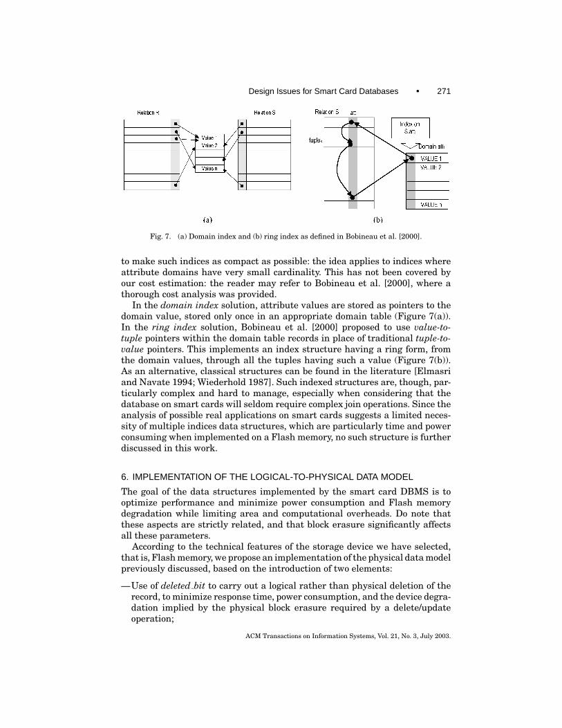
Fig. 7. (a) Domain index and (b) ring index as defined in Bobineau et al. [2000].
to make such indices as compact as possible: the idea applies to indices whereattribute domains have very small cardinality. This has not been covered byour cost estimation: the reader may refer to Bobineau et al. [2000], where athorough cost analysis was provided.
In the domain index solution, attribute values are stored as pointers to thedomain value, stored only once in an appropriate domain table (Figure 7(a)).In the ring index solution, Bobineau et al. [2000] proposed to use value-to-tuple pointers within the domain table records in place of traditional tuple-to-value pointers. This implements an index structure having a ring form, fromthe domain values, through all the tuples having such a value (Figure 7(b)).As an alternative, classical structures can be found in the literature [Elmasriand Navate 1994; Wiederhold 1987]. Such indexed structures are, though, par-ticularly complex and hard to manage, especially when considering that thedatabase on smart cards will seldom require complex join operations. Since theanalysis of possible real applications on smart cards suggests a limited neces-sity of multiple indices data structures, which are particularly time and powerconsuming when implemented on a Flash memory, no such structure is furtherdiscussed in this work.
6. IMPLEMENTATION OF THE LOGICAL-TO-PHYSICAL DATA MODEL
The goal of the data structures implemented by the smart card DBMS is tooptimize performance and minimize power consumption and Flash memorydegradation while limiting area and computational overheads. Do note thatthese aspects are strictly related, and that block erasure significantly affectsall these parameters.
According to the technical features of the storage device we have selected,that is, Flash memory, we propose an implementation of the physical data modelpreviously discussed, based on the introduction of two elements:
—Use of deleted bit to carry out a logical rather than physical deletion of therecord, to minimize response time, power consumption, and the device degra-dation implied by the physical block erasure required by a delete/updateoperation;
ACM Transactions on Information Systems, Vol. 21, No. 3, July 2003.
272 • Bolchini et al.
—Introduction of a number of dummy records per block, allowing the controlof the filling of a block and the organization of the records within the block.Such techniques are already widely used in the management of several datastructures; noticeable examples can be found in B-trees of order n, whereeach node can host a number of items varying from n/2 to n, or in statichash tables where the filling of pages is controlled in order to avoid too manycollisions [Elmasri and Navate 1994; Wiederhold 1987].
These two aspects are discussed in Sections 6.1 and 6.2, focusing on theirbenefits and costs, and comparing them with a straightforward implementationof the identified data structures according to traditional approaches.
6.1 Use of deleted bit
The introduction of this bit positively affects performance every time a recordneeds to be deleted and a logical elimination of the record can be performedrather than the physical one. This technique has been adopted for the followingthree basic situations:
6.1.1 Record Deletions. The deletion of a record in a block requires deter-mining the location of the record (by means of a search) within a block andthe erasure and reprogramming of the block. In order to save time, a deletecan be managed by means of an additional bit per record, deleted bit, to be set(programmed) to 1 when the record is deleted and not valid anymore.
This will cause the presence of invalid records within a block, which leadsboth to a waste of space and a performance degradation in all operations involv-ing a search. This problem is solved by performing a garbage collection-like op-eration during each erase/program cycle of a block, where only the valid recordsare programmed, according to the data structure (heap, ordered, . . . ). This so-lution allows us to reduce the number of erasures to be performed, exploitingthe necessary ones to carry out also the pending delete requests.
6.1.2 Record Updates. Update operations are often seen as a sequence ofdelete and insert operations. In our technological scenario, the delete operationconsists of programming deleted bit, and introducing a new record. In a sortedrelation and in the case of a circular list, when updating a random record (notthe last one) the insertion requires the erase/program operation for at leastone block; thus there is no gain in interpreting the update operation as anindependent delete followed by an insert.
On the other hand, if the insertion requires no ordering, as in the heap andthe circular list (when updating the last record) data organization, the updateconsists of two program operations, a convenient solution in terms of both timeand endurance. As a result, depending on the type of data organization, theupdate consists of the deletion of a record and the introduction of a new in-dependent one, or of the erase/program of the block containing the involvedrecord.
6.1.3 Circular Lists Implementation. The circular list data organizationrequires an append operation and a delete operation for each inserted element.
ACM Transactions on Information Systems, Vol. 21, No. 3, July 2003.

Design Issues for Smart Card Databases • 273
Fig. 8. Circular list implementation by means of a sliding window.
Independently of how the list is organized (single or multiblock), each updaterequires the erasure of the block impacting energy consumption, enduranceand performance.
Let j denote the number of records to be provided by the circular list2 and kthe actual number of physical records used to implement the mechanism. Theuser view of data is obtained by means of a sliding window j records long, whilethe actual space allocated to the circular list is k records long. In this way, thenumber of data observable by the user is constant, equal to j, and independentof time. This data organization allows us to save energy and maxime perfor-mance, but consumes space. Figure 8 shows data organization and its potentialevolution in the case of k = 2 ∗ j ; the gray area represents the sliding window.
Let us assume the initial situation shown in Figure 8(a) with the j elementsalready inserted; when a new element is appended, the first valid element ofthe list is deleted and the window slides (the situation in Figure 8(b)). Afterk − j appends (Figure 8(c)) the available space is used up and a block erasehas to be performed before a new append can be completed (Figure 8(d)). It isworth noting that the erase operation has period k − j and is independent ofthe number of blocks involved.
6.2 Use of Dummy Records
By further exploiting the idea of reducing memory modifications by deletingrecords logically rather than physically (except when necessary), we introducea storage management policy that “leaves” unused records, so that subsequentinsert operations requiring an ordering may be performed without moving thepreexisting records. The term dummy record has been selected to identify theseunused records among the ones containing the relation data.
6.2.1 Sorted Data Structure Implementation. Insert operations on a sortedrelation are characterized by a high probability to cause a block erasure in orderto insert the new record (unless an append situation occurs) and eventuallycause the adjacent and following blocks to be erased and reprogrammed too.
2It is worth noting that it is not relevant whether the physical elements are concentrated into asingle block or are distributed on more blocks.
ACM Transactions on Information Systems, Vol. 21, No. 3, July 2003.
274 • Bolchini et al.
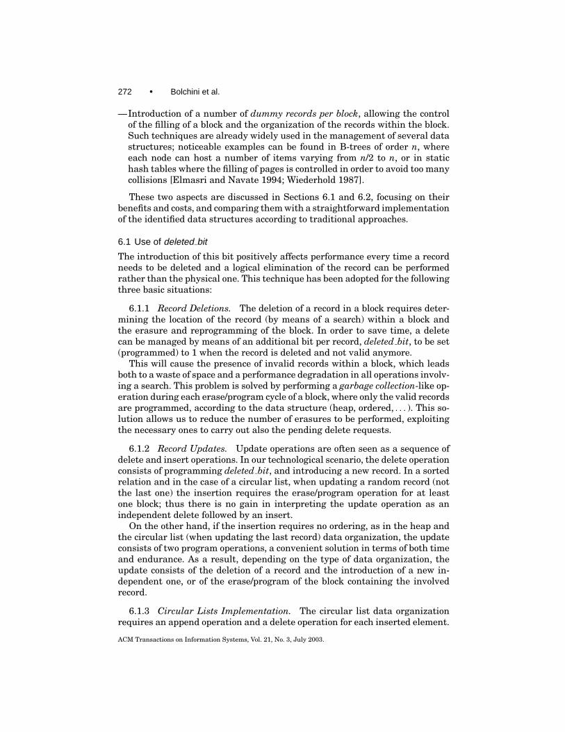
Fig. 9. The buffer of d dummy records out of the n records of the block.
This (these) block(s) erase/program task has (have) a significant overheadin terms of time, power, and endurance. Indeed, the analysis of the actual op-erations to be carried out relates to the general considerations presented inSection 5, with the only exception related to the fact that the entire block iserased when the operation requires it. The use of deleted bit and its impacton the operation costs is straightforward; thus, our physical implementationpolicy has envisioned two alternative physical data organizations to limit theoverall number of erase/program operations, both based on the use of dummyrecords.
For each n-records sized block of memory, d empty records are used as buffersto be left empty and used as the block gets filled; the aim of these records is toreduce the number of blocks involved by the insert operation, possibly to oneblock, the one where the record is to be inserted. Consider the following situationwith respect to the insert operation. In this policy, for the insertion of the firstn records, the existence of the dummy buffer does not introduce any differenceand Block 1 is totally filled. When the next record needs to be inserted, the totalof n+ 1 records will be distributed between the two blocks (two erase/programoperations) so that in Block 1 there is a buffer of d empty records and d + 1records are stored in Block 2. The next insertion will most probably (unless anappend occurs and only a program operation is performed) require modifying(erasing and programming) either Block 1 or Block 2, since now there is roomin the buffer of Block 1 (e.g. Figure 9). Thus, the main difference in the behaviorof the data structure with respect to a structure with no dummy records canbe seen after the first n records are inserted, introducing a different number oferase/program operations. Clearly, there is a complexity overhead due to recordmanagement and to the need for additional counters for keeping track of thecurrent space in the blocks; moreover, depending on the location of the dummybuffer, there is an impact on read operations.
Different scenarios have been taken into consideration, with respect to theposition of dummy records. Considering the locality of dummy records, the al-ternatives are as follows:
—dummy records are all adjacent, either at the beginning or at the end of theblock, or
—dummy records are distributed in the block.
ACM Transactions on Information Systems, Vol. 21, No. 3, July 2003.

Design Issues for Smart Card Databases • 275
The policies are described in the following two sections, and the simulationsof their behaviors are compared in Section 6.4.3.
6.2.2 Adjacent Dummy Records Policy. By keeping all used records adja-cent to one another (as well as the dummy ones), search operations are efficient,since the scanned records are only the valid ones; in fact, given x valid recordsout of the total n records of the block, the cost of a search relates to x ratherthan to n.
Delete. deleted bit is programmed. Cost: search + program.
Update. The block is erased and programmed with the modified record.Cost: search + erase + program. It is worth noting that no overflow ever occursin the following block.
Insert. The operation cost, when involving a single block, is that of a search,plus the cost of a program and, if it is not an append kind of insertion, there isthe added cost of the erase. Altogether, the costs are as follows:
—Insert (append): search + program;—Insert (no append): search + erase + program.
In case there are no dummy records available, this operation may cause anoverflow in the block where the new record is to be inserted. Actually, dependingon the emptiness level of the following blocks, a waterfall mechanism may startto redistribute records in the blocks. In the worst case, all the blocks of therelation need to be erased and programmed. Do note that, depending on thedistribution of the valid records, it might happen that, when inserting a newrecord, if the following blocks are full (and thus there are free records in thepreceding blocks, otherwise the insertion would be forbidden), even a blockpreceding the one where the record is to be inserted needs to be erased andprogrammed.
Insertions are managed as follows: the first n records are inserted in the firstblock. When the n + 1th record needs to be inserted, n − d records remain inthe first block and, d + 1 are programmed in the second block; as a result, thefirst block is erased and programmed, while the second one is programmed.
The next d insertions require the erasure of a single block (they possibly canfit all in the first block).
When the total number of valid records of all blocks of the relation reaches(n−d )×b, two approaches can be adopted: either the remaining dummy recordsare redistributed among the blocks or no further movement of records is per-formed in order to provide a limited number of dummy records per block. Ofcourse, when the number of valid records is equal to n× b, no further recordscan be inserted.
6.2.3 Distributed Dummy Records Policy. By considering an even distribu-tion of the records to be inserted with respect to the sort key, the use of adjacentdummy records limits the number of blocks involved in the operation to one.Nevertheless, in order to perform the insertion of a record in the correct order,
ACM Transactions on Information Systems, Vol. 21, No. 3, July 2003.
276 • Bolchini et al.
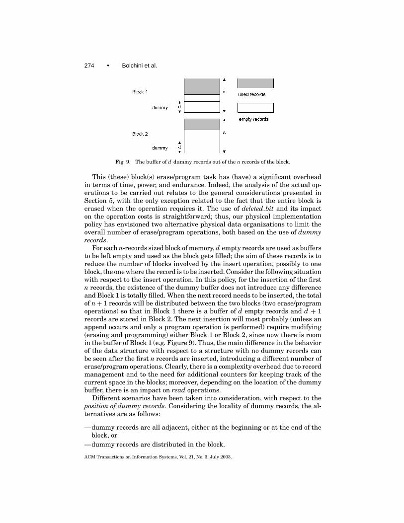
Fig. 10. Distributed dummy records per block to reduce the number of program/erase operations.
if all records are inserted adjacent to one another, the probability of erasing theblock that will contain the record is very high.
As a consequence, in order to keep the probability of block erasure low, thedummy records are evenly distributed through the block so that each recordis inserted according to the defined order, leaving empty records between theexisting records in the block. This is achieved by means of an address-mappingfunction (similar to a hash function) that, given the sort key value, determinesthe address in the block of the record to be inserted (Figure 10).
The sequence shown in Figure 10 refers to four insert operations in an or-dered fashion: each time an insert is performed, the address-mapping functionis evaluated on the value of the field with respect to which ordering is main-tained. The address-mapping function is implemented in hardware exploitingthe additional spare logic available in the smart card architecture.
To appreciate the effectiveness of the use of dummy records, consider thediagram shown in Figure 11, where each tile represents a block erasure dueto an insert operation. As an example, consider the traditional sorted relationmanagement (first diagram). After the first three operations, a block erasureoccurs on the sorted relation with no particular management policy; the sameoccurs with the adoption of the deleted bit policy. Such an event does not occuruntil the 30th operation, when dummy records are used.
The introduction of deleted bit reduces the number of block erasures (26)with respect to the traditional, straightforward approach (31); the adoption ofdummy records significantly improves the performance, requiring only sevenerasures, confirming the expected results.
6.3 Overheads
The introduction of the proposed logical and physical implementation strategiesare characterized by costs in terms of area for storing the additional informationand management for maintaining a consistent data and control information.
6.3.1 Deleted and Validity Bits Implementation. The additional bits formanaging records with both the deleted bit strategy and the validity bit strat-egy (associated with the dummy records policy) have been represented as partof the data record. Such a representation is a logical one: at the physical level,in order to optimize control bit manipulation, we group them at the beginning(or at the end) of a memory block, as shown in Figure 12.
This separation between control bits and data allows one to optimize theaccess to valid records and to delimitate the range of action on the memory
ACM Transactions on Information Systems, Vol. 21, No. 3, July 2003.

Design Issues for Smart Card Databases • 277
Fig. 11. Block erasure operations caused by a sequence of access operations (insert, select, delete,and update) on a sorted relation; each tile represents one block erasure. Three different datastructures are compared: sorted, sorted with deleted bit, sorted with dummy records.
Fig. 12. Flash memory block organization with specific records for control bits (deleted and/orvalidity) and data.
block for updating the status of a record. It is worth noting that both typesof control bits need to be written when a record is first valid and when it isdeleted. Thus data record modification implies the programming of control bits,never the erasure, unless the record needs to be physically deleted. In such acase, though, the entire block is erased together with its control bits. As a result,the programming of control bits and their storage in nonvolatile memory doesnot introduce any overhead in terms of additional block erasure operations; theoverhead only consists of the memory block space devoted to such accessoryinformation.
ACM Transactions on Information Systems, Vol. 21, No. 3, July 2003.

278 • Bolchini et al.
6.3.2 Counter and Pointer Management. For the circular list data struc-ture and for the concentrated dummy records strategy, additional informationindicating the first available data record is necessary and needs to be stored innonvolatile memory as well. Such a requirement leads to the reservation of acontrol memory block for hosting all the pointers. In order to reduce the numberof update operations on the NVM it is possible to investigate the possibility ofloading such a block of information into RAM at the beginning of the applica-tion operations and to keep up-to-date information there. Immediately beforeterminating the application, the memory block with the pointers is updated,dumping the information stored in RAM.
7. EXPERIMENTAL EVIDENCE
A simulator has been developed, modeling the CPU, RAM, and Flash memories,and the system bus, to evaluate the behavior of the proposed data structures andtheir impact on the parameters determining performance, power consumption,and response time. More in detail, the user can characterize the system modelin terms of the following:
—architectural model;—Data and address bus;
—memory model:—Flash memory block size/number;—RAM memory size;
—data model:—relation cardinality,—record size;
—Model of the operations performed on the data:—number of select/delete/update operations,—Data set (random generated/user provided).
The evaluation parameters taken into consideration are as follows:
—number of read/written bits (related to response time/power consumption),—number of bits on the data bus (related to power consumption),—number of changing bits on bus (related to power consumption),—number of block erasures (related to response time/power consumption), and—area.
Once the architecture and data structure have been selected, it is possibleto simulate the performance and costs of the adopted data structure either onrandomly generated or on user-defined input data. The analysis of the experi-mental results is reported in the next sections, for a complete evaluation of theproposed approach.
ACM Transactions on Information Systems, Vol. 21, No. 3, July 2003.

Design Issues for Smart Card Databases • 279
7.1 Benefits and Costs Evaluation When Using deleted bit
The introduction of deleted bit improves performance but introduces costs interms of space overhead and computational complexity (and consequently in-creases response time). Space overhead is deleted bit itself, one for each record,while computational overhead refers to the time necessary to control deleted bitin order to determine if the record needs to be handled or not. A set of exper-iments has been carried out to compare the traditional heap and circular listimplementations to the proposed implementations adopting deleted bit.
The experimental setup for this comparison adopted for all the analyseswe carried out has been built by randomly generating the data set, and byapplying a mixed sequence of access operations to simulate a real workload. Foreach emulated situation 50 different simulations have been repeated, finallyreporting the mean value. Figure 13 shows the results for the heap relation case.
The graph in Figure 13(a) shows the average probability of block erasuresthat occurred during a sequence of 100 operations inserting, deleting, updat-ing and selecting data. The graph in Figure 13(b) shows the number of blockerasures occurring during a single simulation in the traditional and in thedeleted bit case. The graphs in Figures 13(c) show the number of read/writeoperations on the Flash memory for the same sequence of operations and theaverage read/written kbytes from Flash in order to perform such operations,respectively.
As expected, in the traditional implementation, each delete and update op-eration causes a block erasure, and the situation does not change during time,since the Flash memory block only contains valid records. Things are differentin the deleted bit implementation. At the beginning, record deletion and updateare performed by invalidating the current record and, in the case of an update,the insertion of the modified record. This behavior does not force any block era-sure until the moment when there are no spare records in the block. At thatpoint, a block erasure occurs, a garbage-collection-like operation occurs, andthe memory block is left with only valid records. The probability that this eventoccurs before the first 50 to 60 operations is zero with respect to the simulationresults.
Clearly this behavior somewhat depends on the data set used and the se-quence of operations, but the use of 50 different simulations should limit theirinfluence. The graph of the average probability does not show that, once theblock erasure occurs, the probability goes back to zero until the subsequentblock erasure, exposing a quasiperiodical behavior. Therefore, the two tracesof block erasures are reported in the middle graph, to better highlight such abehavior. In order to expose such a periodical occurrence in the case of the heapimplemented with the deleted bit approach, the test sequence was composed of400 operations.
As can be noted, the introduction of deleted bit reduces both the amount ofaccessed data and the number of block erasures, thus leading to a performanceimprovement and to reduced power consumption. Specifically, for the set ofreported experiments, there was an average reduction of 15% for read operationand of 27% in write operations when using deleted bit.
ACM Transactions on Information Systems, Vol. 21, No. 3, July 2003.

280 • Bolchini et al.
Fig. 13. Performance impact due to the introduction of deleted bit with a heap relation.
Simulation has also been carried out with the distributed dummy physi-cal implementation, without achieving significant results: the number of era-sures was comparable to that of the traditional implementation, and sometimesworse. This is the result we expected: maintaining an ordered relation is ex-pensive and only in exceptional situations can such costs be balanced by blockerasures caused by a highly volatile heap relation.
ACM Transactions on Information Systems, Vol. 21, No. 3, July 2003.

Design Issues for Smart Card Databases • 281
Table IV. Access Timing Costs for the Different Sorted Data Policies
Adjacent dummy/No dummy Distributed dummyScan B×TR× (FRR+C) B×R× (FRR+C)Search eq. 2×FRR×Log2 B+C×Log2 TR 1/2B×R× (FRR+C)Search range TSEQ EQ+ (FRR+RWR)×n r B×R× (FRR +C)+ (FRR+RWR)×n rInsert PCD× (FRR×TR+C+FWR)+
(1–PCD)×TDE
PDD× (FRR×R+C+FWR)+(1− PDD)×TDE
Delete TSEQ EQ+ (FRR+FWR+RRR+RWR)×R+C+BE
TINS
Update TDE TSEQ EQ+ (FRR+FWR+RRR+RWR)×R+C+BE
7.2 Benefits and Costs Evaluation When Using Dummy Records
The adoption of dummy records reduces time and power consumption when in-troducing new records in a sorted relation, causing possible performance degra-dation in the search task due to the presence of nonsignificant records (thedummy ones) that nevertheless need to be recognized as such. Table IV showsa comparison of the costs with respect to the three physical data organizationsdiscussed above. A few additional notations are introduced, to distinguish be-tween valid, deleted and dummy records, and precisely:
—DR: number of deleted records;—VR: number of valid records;—TR: total number of programmed records (valid or deleted).
It is worth noting that when a relation fits completely on a single block onlythe distributed and no dummy organizations need to be considered, since theadjacent dummy organization provides the same performance as the no dummyone.
These formulas do not include the pointer to the last valid record (adja-cent dummy policy) and the valid bit (distributed dummy policy) managementcontributions, considering that such data are loaded into the CPU before pro-cessing the records, thus requiring a unique additional reading operation fromthe Flash memory. Nevertheless, such contributions have been explicitly takeninto account during simulation, where the count of the number of read andwritten bits also includes access cost for control information.
The two dummy records management policies have been simulated in orderto compare their performance; results for the search and insert operations areshown in Figures 14(a) 14(b).
There is still a final consideration: there are two phases in the life of a smartcard database: an initial transient phase, when data is mainly inserted andupdated, and a second—more stable—phase, where data is mainly accessedfor retrieval. As a consequence, the suitability of a data structure for a givenrelation may change over time, since the expected frequency of the operationscharacterizing the two phases would lead to the selection of different data struc-tures and of their related algorithms.
Power consumption maintains a significant role at all times. When consid-ering the first transient phase, data structures and algorithms are targeted to
ACM Transactions on Information Systems, Vol. 21, No. 3, July 2003.

282 • Bolchini et al.
Fig. 14. Simulation of the search with equality and insert times as a function of the number ofrecords in a block.
Fig. 15. Suitability areas for the considered policies when analyzed on a single block.
limit the number of memory block erasures, identifying a satisfying tradeoffwith respect to space occupation. In the second phase, efficiency in retrievaland data size are predominant aspects. Figure 15 shows a comparison betweenthe different dummy records allocation policies with respect to the mix of oper-ations in the workload.
Since the distributed dummy records approach seems to perform signifi-cantly better during the first initial phase, we carried out a set of experiments tohighlight this situation, by comparing the normal (traditional), the deleted bit(and no dummy), and the distributed dummy solutions, as we already showedin Section 6.3.2. The results are reported in Figure 16, where a sequence of250 operations has been applied to the three physical data structures, startingfrom an empty memory. One hundred simulations for each setup have beenperformed to achieve the values of the probability of block erasures. A different
ACM Transactions on Information Systems, Vol. 21, No. 3, July 2003.

Design Issues for Smart Card Databases • 283
Fig. 16. Performance comparison for a mixed sequence of operations: the distributed dummy solu-tion is well below the normal and deleted bit solutions, significantly reducing the number of blockerasures required to maintain a sorted relation.
representation of the results with respect to the one used in Figure 11 hasbeen adopted to better point out the differences between performances. For thesake of clarity, the adjacent dummy approach is not reported leading to resultssimilar to the deleted bit ones.
As can be seen in Figure 16, the distributed dummy requires a lower num-ber of block erasures (bottom trend line), followed by the deleted bit and nor-mal implementations, during the entire sequence of operations. This will leadto reduced power consumption and response times in performing the desiredoperations.
It is worth noting that the deleted bit solution, which significantly improvesa heap relation, does not provide the same relevant advantages in the case ofa sorted relation. As has already been pointed out, in fact, the maintenance ofthe ordering forces many modifications in the relation records, thus requiringfrequent block erasures. Yet, when the volatility of data lowers, that is, in thesecond phase of the database life, when data is mainly retrieved and seldommodified, the use of deleted bit could substitute for the dummy solution in orderto lower costs without requiring too many block erasures.
7.3 Overall Evaluation
Each one of the proposed logical and physical data structures has been charac-terized in terms of costs and benefits, in order to be able to compare the differentsolutions for each relation while trying to identify the most promising databaseimplementation. Each of the significant elements has been introduced as a con-tribution to a cost function that computes the cost of each implementation and
ACM Transactions on Information Systems, Vol. 21, No. 3, July 2003.

284 • Bolchini et al.
identifies for each relation the most convenient solution, exploring the entiresolution space.
Such a cost function is also used to evaluate the performance and costs ofthe possible approaches also considering the expected volatility of relations (thenumber of changing records within a relation during time) to explore the possi-bility of adopting different physical data structures based on the “evolutionaryphase” of the relation, initial/startup, or stable phase.
8. CONCLUSIONS AND FUTURE DEVELOPMENTS
This research proposes a methodology for smart card database design usingFlash-EEPROM storage; the process is strongly driven by the technological is-sues, which impose a very careful design on the logical and physical data struc-tures in order to meet the constraints the smart card architecture introduces,and to provide satisfactory performance.
In this paper we concentrated on the logical-physical smart card databasedesign phase, with attention to the most appropriate data structures and algo-rithms that must be made available for the database designer to choose. Ouranalysis pointed out that there are several factors guiding the selection of themost suitable data structures when deriving the physical database design fromthe annotated logical schema: power consumption, endurance, performance,physical size requirements.
We examined a number of data structures with respect to the insertion,search with equality, search with range selection, and delete and update opera-tions, analyzing their features in terms of time performance and memory size.Furthermore, in order to reduce block erasures that, in Flash-EEPROMs, arelengthy, power-consuming, and life-shortening operations, we focused on theinsertion operation in sorted data structures. We introduced a set of dummyrecords and compared two different policies for their allocation.
We found that the performance of the two allocation policies differ with re-spect to the mix of operation types. In particular, the distributed dummy recordspolicy is well suited at times when the database contents undergo deep changes,whereas the no dummy or adjacent dummy records policies are suited whenmost of the operation involves retrieval queries. Simulation results supportingthe described behavior are shown.
Our proposal focuses on the logical and physical data structures designed tosupport a database approach for managing data stored in a smart card. Futurework on the methodology will address the following aspects:
—the “upper parts” of the methodology tree, in order to find design, fragmen-tation and allocation criteria for the different logical units (e.g., tables) of thesmart card database;
—ad hoc architectural enhancements, with particular attention to the smartcard processor, to the instruction set, to power consumption, to the possibilityof implementing different storage technologies on the same card in order tobenefit from their peculiarities, and to the analysis of other data managementpolicies for performance optimization.
ACM Transactions on Information Systems, Vol. 21, No. 3, July 2003.

Design Issues for Smart Card Databases • 285
We will also investigate the following other interesting research issues re-lated to smart card technology:
—transaction management to guarantee data consistency, especially useful forsituations where a card is disconnected (e.g. extracted from the reader) beforecommitting the transaction;
—synchronization between the smart card database and the central one, hostedby a server, when smart card data processing is performed off-line.
It is important to notice that the proposed design methodology can be adoptedindependently of these last two points, since many applications do not require acentral server database at all, while others do not need implementation of a fulltransaction environment, only requiring a minimal amount of data consistency.
REFERENCES
ATZENI, P., CERI, S., PARABOSCHI, S., AND TORLONE, R. 2000. Database Systems. McGraw-Hill,New York, NY.
BOBINEAU, C., BOUGANIM, L., PUCHERAL, P., AND VALDURIEZ, P. 2000. PicoDBMS: Scaling downdatabase techniques for smart card. In Proceedings of the 26th International Conference on VeryLarge Databases. 11–20.
BOLCHINI, C. AND SCHREIBER, F. A. 2002. Smart card embedded information systems: A methodol-ogy for privacy oriented architectural design. Data & Knowl. Eng. 41, 2-3, 159–182.
BUTLER, M. J., HARTEL, P. H., DE JONG, E., AND LONGLEY, M. 2001. Transacted memory for smartcards. In Proceedings FME 2001, Formal Methods for Increasing Software Productivity. 478–499.
CERI, S. AND PELAGATTI, G. 1984. Distributed Databases: Principles and Systems. McGraw-Hill,New York, NY.
EICH M. H. 1992. Main memory databases: Current and future research issues. IEEE Trans.Knowl. Data. Eng. 4, 6, 507–508.
ELMASRI, R. AND NAVATHE, S. H. 1994. Fundamental of Database Systems. 2nd ed. BenjaminCummings, Redwood City, CA.
GARCIA-MOLINA, H. AND SALEM, K. 1992. Main memory database systems: An overview. IEEETrans. Knowl. Data. Eng. 4, 6, 509–516.
ITGOV. 2002. Smart card adoption for ID application in the Italian Government. Available onlineat http://www.innovazione.gov.it/ita/comunicati/2002 02 08cie.shtml.
RAMAKRISHNAN, R. AND GEHRKE, J. 2000. Database Management Systems, 2nd ed. McGraw-Hill,New York, NY.
RANKL, W. and EWFFING, W. 1999. Smart Card Handbook, 2nd ed. Wiley, New York, NY.STOCKDILL, R. 2002. STMicroelctronics debuts word’s most advance smart card memory tech-
nology. STMicroelectronics Technical Press Relations, Carrollton, TX. Available online at http://www.st.com/stonline/press/news/year2002/p1249.htm.
SUN MICROSYSTEMS. 1999. JavaCard 2.1 Application Programming Interface Specification, Java-Soft Documentation. Sun Microsystems, Santa Clara, CA.
SUTHERLAND, J. and VAN DEN HEUVEL, W. J. 2002. Enterprise application integration and complexadaptive systems. Comm. of ACM, 45, 10, 59–64.
TAMER, O. M. AND VALDURIEZ, P. 1991. Principles of Distributed Database Systems. Prentice Hall,Englewood Cliffs, NJ.
WIEDERHOLD, G. 1987. File Organization for Database Design. McGraw Hill, New York, NY.
Received August 2002; revised January 2003; accepted May 2003
ACM Transactions on Information Systems, Vol. 21, No. 3, July 2003.