Logic Synthesis with VHDL System Synthesis - …dropzone.tamu.edu/~wshi/468/vhdl_system.pdf ·...
35
Logic Synthesis with VHDL System Synthesis Bob Reese Electrical Engineering Department Mississippi State University
Transcript of Logic Synthesis with VHDL System Synthesis - …dropzone.tamu.edu/~wshi/468/vhdl_system.pdf ·...
Logic Synthesis with VHDLSystem Synthesis
Bob ReeseElectrical Engineering Department
Mississippi State University
Mississippi State UniversityElectrical & Computer Engineering
System Design with VHDLSystem–2 Bob Reese 5/95
VHDL Packages
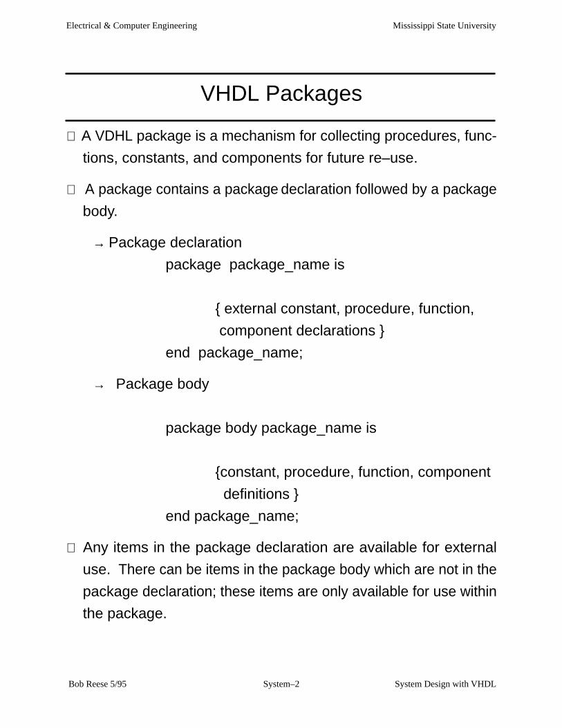
⇒ A VDHL package is a mechanism for collecting procedures, func-
tions, constants, and components for future re–use.
⇒ A package contains a package declaration followed by a package
body.
→ Package declaration
package package_name is
{ external constant, procedure, function,
component declarations }
end package_name;
→ Package body
package body package_name is
{constant, procedure, function, component
definitions }
end package_name;
⇒ Any items in the package declaration are available for external
use. There can be items in the package body which are not in the
package declaration; these items are only available for use within
the package.

Mississippi State UniversityElectrical & Computer Engineering
System Design with VHDLSystem–3 Bob Reese 5/95
Example VHDL Package
Library IEEE; use IEEE.std_logic_1164.all;
package iscas is
procedure ripple_adder (a,b: in std_logic_vector; cin: in std_logic; sum: inout std_logic_vector; cout: out std_logic);
end iscas;
package body iscas is
function xor3 (a,b,c: in std_logic) return std_logic is begin return (a xor b xor c); end xor3;
procedure ripple_adder (a,b: in std_logic_vector; cin: in std_logic; sum: inout std_logic_vector; cout: out std_logic) is
variable c: std_logic_vector((a’high–a’low+1) downto 0); begin c(0) := cin; for i in 0 to (a’high–a’low) loop sum(i+sum’low) := xor3 (a(i+a’low), b(i+b’low), c(i) ); c(i+1) := (a(i+a’low) and b(i+b’low)) or
(c(i) and (a(i+a’low) or b(i+b’low))); end loop; cout := c(c’high); end ripple_adder;
end iscas;

Mississippi State UniversityElectrical & Computer Engineering
System Design with VHDLSystem–4 Bob Reese 5/95
VHDL Functions
⇒ General form:
function function_name ( parameter list) return return_type is
{variable declarations}
begin
{sequential statements}
end function_name;
function xor3 (a,b,c: in std_logic) return std_logic is begin return (a xor b xor c); end xor3;
⇒ A VHDL function computes a return value based upon its parame-
ter list.
→All parameters passed to a VHDL function must be of mode in;
i.e, the function is not allowed to modify any of the function
parameters.
→ The default class of the elements in a parameter list for either
procedures or functions is variable.
→ Signals can be passed in the parameter list; in this case the
parameter list would look like:
(signal a, b, c: std_logic)
→ More on the difference between variables and signals will be
given later.
Mississippi State UniversityElectrical & Computer Engineering
System Design with VHDLSystem–5 Bob Reese 5/95
VHDL Procedures
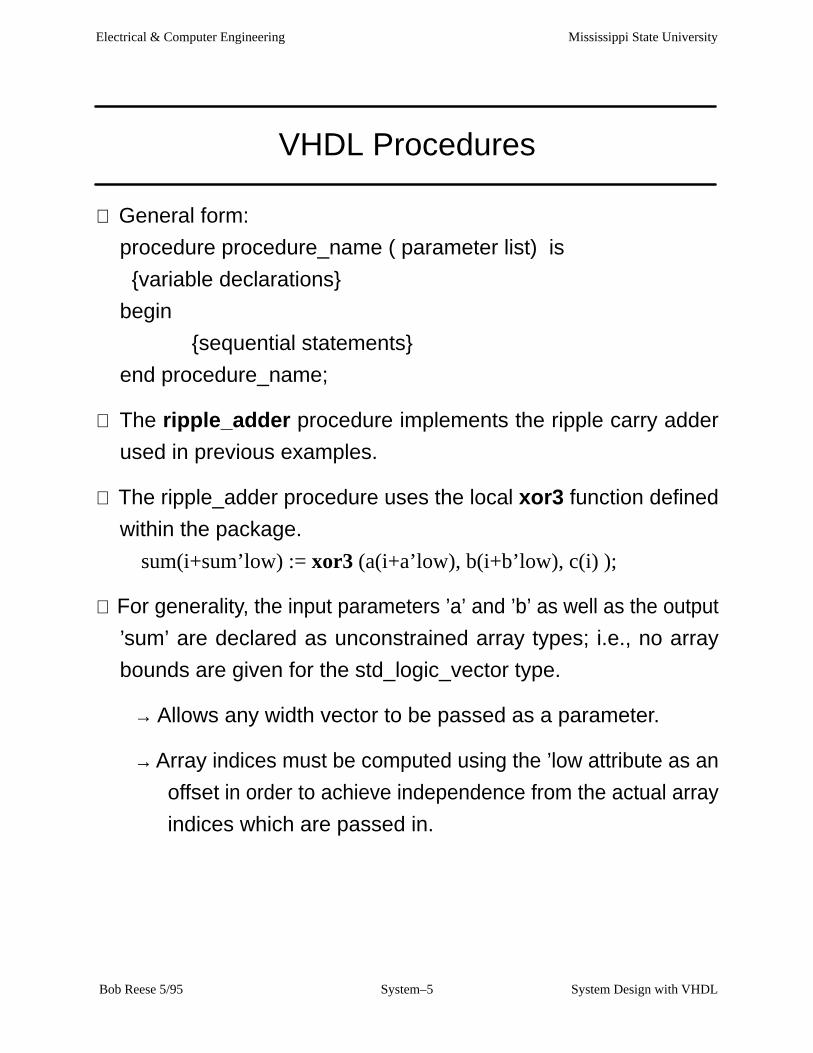
⇒ General form:
procedure procedure_name ( parameter list) is
{variable declarations}
begin
{sequential statements}
end procedure_name;
⇒ The ripple_adder procedure implements the ripple carry adder
used in previous examples.
⇒ The ripple_adder procedure uses the local xor3 function defined
within the package.
sum(i+sum’low) := xor3 (a(i+a’low), b(i+b’low), c(i) );
⇒ For generality, the input parameters ’a’ and ’b’ as well as the output
’sum’ are declared as unconstrained array types; i.e., no array
bounds are given for the std_logic_vector type.
→ Allows any width vector to be passed as a parameter.
→ Array indices must be computed using the ’low attribute as an
offset in order to achieve independence from the actual array
indices which are passed in.

Mississippi State UniversityElectrical & Computer Engineering
System Design with VHDLSystem–6 Bob Reese 5/95
Signals vs Variables
⇒ Only signals are used as the connection ports for VHDL entities.
→ Variables are declared within process blocks, procedures,
and functions.
→ Signals can only be declared within architecture bodies; they
can be passed as parameters to functions and procedures.
⇒ Signals are assigned via ”<=”; Variables are assigned via ”:=”.
⇒ From a simulation point of view:
→ Signals have events occurring on them and this event history
is tracked via an internal event list.
→ Signal assignment can be delayed such as:
a <= ’1’ after 10 ns
→ Variable assignment is always immediate.
a <= ’1’;
→ Signals require more overhead in terms of storage and
simulation time than variables. A general rule of thumb is to
use variables wherever possible.
⇒ From a synthesis point of view, both variables and signals can turn
into internal circuit nodes.

Mississippi State UniversityElectrical & Computer Engineering
System Design with VHDLSystem–7 Bob Reese 5/95
Using the ripple_adder Procedure
Library IEEE;use IEEE.std_logic_1164.all;use work.iscas.all;
entity adder_test isport ( signal a,b: in std_logic_vector (15 downto 0); signal cin: in std_logic; signal sum: out std_logic_vector(15 downto 0); signal cout: out std_logic); end adder_test;
architecture behavior of adder_test is
begin process (a,b,cin) variable temp_sum: std_logic_vector (sum’range); variable temp_cout: std_logic; begin ripple_adder(a, b, cin, temp_sum, temp_cout); sum <= temp_sum; cout <= temp_cout; end process; end behavior;
’work’ is the default library name forpackages. The ’all’ keyword says touse all externally available packageitems in the ’iscas’ package.
Call the ’ripple_adder’ procedure.Variables are used as parameterswithin ’ripple_adder’ so variablesmust be passed in as arguments.These variables are then assigned tothe target signals.

Mississippi State UniversityElectrical & Computer Engineering
System Design with VHDLSystem–8 Bob Reese 5/95
A Carry Select Adder
A
B
CI
COUT
SUM
A
B
CI
COUT
SUM
0
A
B
CI
COUT
SUM
1
0
1
MUX
CS0
CS0
A
B
CI
COUT
SUM
0
A
B
CI
COUT
SUM
1
0
1
MUX
CS1
CS1 CS2
....... etc.
K bits
L bits
M bits
SUM
SUM
SUM
Each stage computes part of thesum. Typically, the stage sizes in-crease; so a 16 bit adder stagesizes might be 4, 5, 7 = total of16 bits. Ripple adders are usedfor stage adders.

Mississippi State UniversityElectrical & Computer Engineering
System Design with VHDLSystem–9 Bob Reese 5/95
Carry_Select_Adder Procedure
procedure carry_select_adder (groups: iarray; a,b: in std_logic_vector; cin: in std_logic; sum: inout std_logic_vector; cout: out std_logic) is
variable low_index, high_index :integer; variable temp_sum_a, temp_sum_b : std_logic_vector(sum’range); variable carry_selects :std_logic_vector(groups’range); variable carry_zero :std_logic_vector(groups’low to (groups’high–1)); variable carry_one :std_logic_vector(groups’low to (groups’high–1));
begin low_index := 0; for i in groups’low to groups’high loop high_index := (groups(i)–1) + low_index ; if (i = 0) then –– first group, just do one ripple–carry
ripple_adder (a(high_index downto low_index), b(high_index downto low_index), cin, sum(high_index downto low_index), carry_selects(0) );
else–– need to do two ripple carry adders then use mux to select ripple_adder (a(high_index downto low_index), b(high_index downto low_index),
’0’, temp_sum_a(high_index downto low_index), carry_zero(i–1));
ripple_adder (a(high_index downto low_index), b(high_index downto low_index), ’1’, temp_sum_b(high_index downto low_index), carry_one(i–1));if (carry_selects(i–1) = ’0’) then
sum(high_index downto low_index) := temp_sum_a(high_index downto low_index); else sum(high_index downto low_index) := temp_sum_b(high_index downto low_index);
end if; carry_selects(i) := (carry_selects(i–1) and carry_one(i–1) ) or carry_zero(i–1); end if; low_index := high_index + 1; end loop; cout := carry_selects(groups’high); end ripple_adder;
Mississippi State UniversityElectrical & Computer Engineering
System Design with VHDLSystem–10 Bob Reese 5/95
iscas Package Declaration
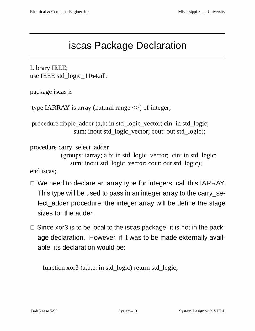
Library IEEE;use IEEE.std_logic_1164.all;
package iscas is
type IARRAY is array (natural range <>) of integer;
procedure ripple_adder (a,b: in std_logic_vector; cin: in std_logic; sum: inout std_logic_vector; cout: out std_logic);
procedure carry_select_adder (groups: iarray; a,b: in std_logic_vector; cin: in std_logic;
sum: inout std_logic_vector; cout: out std_logic);end iscas;
⇒ We need to declare an array type for integers; call this IARRAY.
This type will be used to pass in an integer array to the carry_se-
lect_adder procedure; the integer array will be define the stage
sizes for the adder.
⇒ Since xor3 is to be local to the iscas package; it is not in the pack-
age declaration. However, if it was to be made externally avail-
able, its declaration would be:
function xor3 (a,b,c: in std_logic) return std_logic;
Mississippi State UniversityElectrical & Computer Engineering
System Design with VHDLSystem–11 Bob Reese 5/95
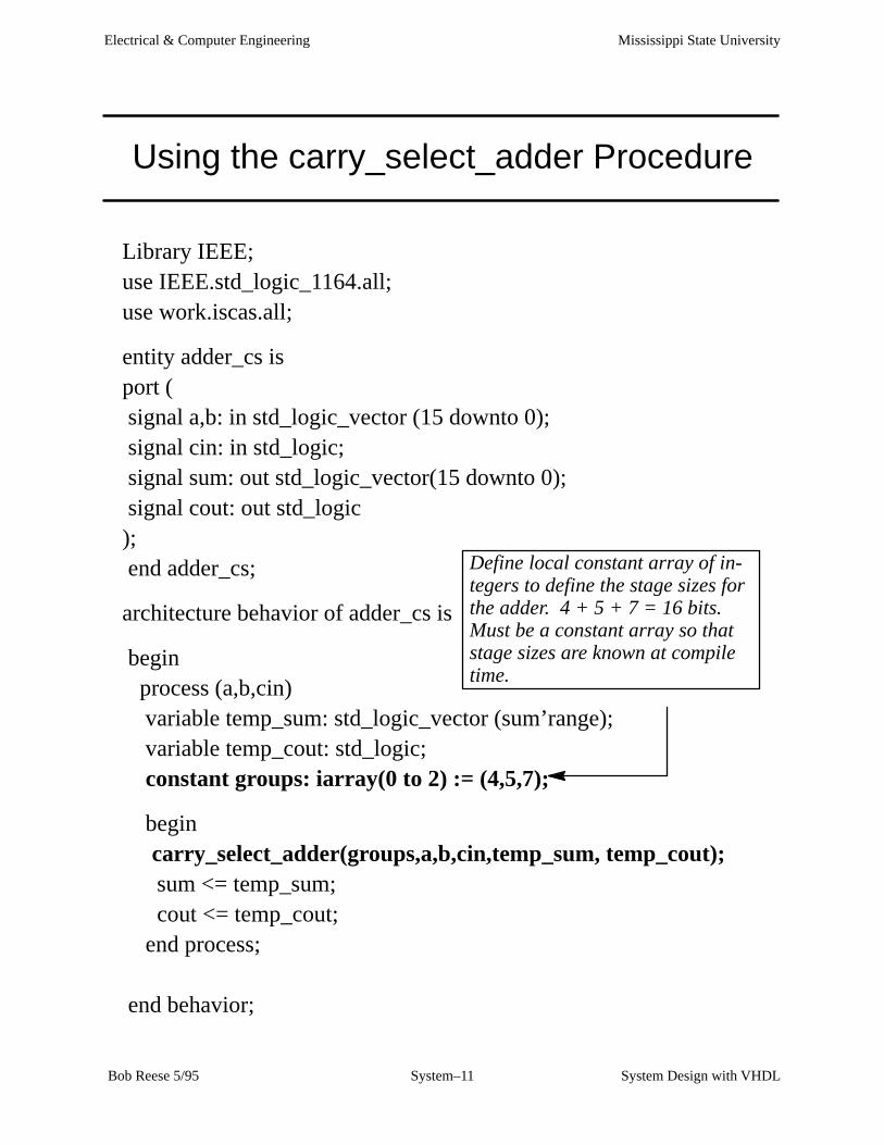
Using the carry_select_adder Procedure
Library IEEE;use IEEE.std_logic_1164.all;use work.iscas.all;
entity adder_cs isport ( signal a,b: in std_logic_vector (15 downto 0); signal cin: in std_logic; signal sum: out std_logic_vector(15 downto 0); signal cout: out std_logic); end adder_cs;
architecture behavior of adder_cs is
begin process (a,b,cin) variable temp_sum: std_logic_vector (sum’range); variable temp_cout: std_logic; constant groups: iarray(0 to 2) := (4,5,7);
begin carry_select_adder(groups,a,b,cin,temp_sum, temp_cout); sum <= temp_sum; cout <= temp_cout; end process; end behavior;
Define local constant array of in-tegers to define the stage sizes forthe adder. 4 + 5 + 7 = 16 bits.Must be a constant array so thatstage sizes are known at compiletime.

Mississippi State UniversityElectrical & Computer Engineering
System Design with VHDLSystem–12 Bob Reese 5/95
12
34
56
78
12
34
56
78
A B C D
A B C D
4
10
1
0
122 310
12 14
11
10
12
9
4
56
2
1
7
12
4
5
2
1
6
13
14
8
8
14
1
6
6
0
8
9
15
15
10
54893211510
3
12
15
14
14
1311
10
8
8
1113
9
5
7
7
3
15
2
3
8
0
4
2
3
9
1
13
14
8
01413121176
0
11
10
6
6
0
2
12
39
7
1
5
cin
a(15
:0)
a(15
:0)
n10
44
n10
38
n10
31
n10
24
n10
18
n10
11
n1042
n10
27
a(4)
a(6)
a(1)
a(7)
a(11)
a(12)
a(12)
a(8)
a(13)
a(14)
b(1
5:0)
n10
16a(
6)n
1065
b(6
)su
m(6
)
b(7)
b(11)
n10
43
n10
40n
1039
n10
41
n99
3n
1034
n1035
sum
(7)
n10
33
a(7)
n10
37n
1036
b(7
)
n1029
n10
55n
1026
n1028
sum
(11)
n10
25
a(11
)n
1030
b(1
1)
a(12
)n
1063
b(1
2)n
1022
sum
(12)
n10
23
n10
20
n10
19b
(15:
0)n
1021
n10
57n
1013
n1015
sum
(13)
n10
12
a(13
)n
1017
b(1
3)n
1060
a(14
)
a(14
)b
(14)
n10
09su
m(1
4)b
(14)
n10
62n
1010
n10
61
n10
07n
1008
b(1
4)
a(9)
a(0)
sum
(0)
n10
05b
(0)
a(10
)b
(9)
b(1
0)
n1000
a(10
)su
m(1
0)n
1054
n97
6b
(10)
n10
01n
974
sum
(15:
0)n
975
b(4)
b(0
)n
1056
cin
b(1
2)n
973
n96
5b
(0)
a(0)
b(1
0)
n1058
n1059
a(10
)
n984
b(1
)a(
9)n
966
sum
(15)
a(1)
n10
47n
999
b(1
)n
1048
n98
3b
(2)
n98
5
a(2)
b(1
2)n
1014
a(1)
sum
(1)
b(1
3)n
991
b(2
)b
(3)
b(1
)n
967
a(2)
a(3)
a(2)
b(3
)n
988
n96
8b
(2)
sum
(2)
a(3)
a(3)
sum
(3)
n98
7
b(8
)b
(8)
b(3
)
a(8)
n96
2a(
5)n
1006
n10
49n
969
n99
6su
m(9
)n
964
b(8)
b(9
)a(
9)b
(6)
n10
52n
998
n97
2b
(5)
n1053
n994
n97
1
n1032
a(8)
n10
64su
m(8
)n
961
a(6)
n99
5
b(6
)a(
8)
n97
7n
1002
n98
0
n97
9n
981
n97
0su
m(4
)a(
4)n
1046
b(4
)
n1004
a(5)
b(5)
sum(15:0)
n10
03n
1051
n10
50su
m(5
)
n958
n10
45n
982
n99
2
n97
8
n997
n95
9n
960
n96
3
n98
6n
989
n99
0
b(1
5)n
957
a(15
)
cou
tco
ut
a(15
)
b(1
5)
Mississippi State UniversityElectrical & Computer Engineering
System Design with VHDLSystem–13 Bob Reese 5/95
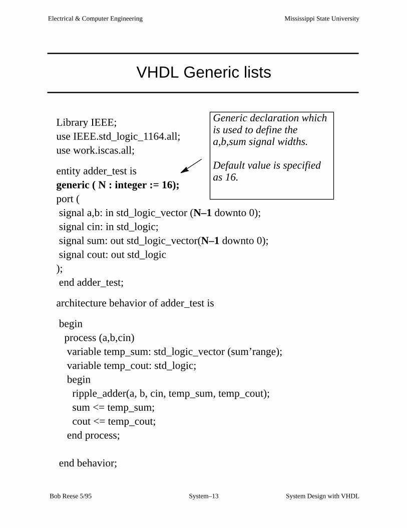
VHDL Generic lists
Library IEEE;use IEEE.std_logic_1164.all;use work.iscas.all;
entity adder_test isgeneric ( N : integer := 16);port ( signal a,b: in std_logic_vector (N–1 downto 0); signal cin: in std_logic; signal sum: out std_logic_vector(N–1 downto 0); signal cout: out std_logic); end adder_test;
architecture behavior of adder_test is
begin process (a,b,cin) variable temp_sum: std_logic_vector (sum’range); variable temp_cout: std_logic; begin ripple_adder(a, b, cin, temp_sum, temp_cout); sum <= temp_sum; cout <= temp_cout; end process; end behavior;
Generic declaration whichis used to define thea,b,sum signal widths.
Default value is specifiedas 16.

Mississippi State UniversityElectrical & Computer Engineering
System Design with VHDLSystem–14 Bob Reese 5/95
VHDL Generic lists (cont.)
⇒ VHDL generic lists are used in entity declarations for passing stat-
ic information.
→ Typical uses of generics are for controlling bus widths, feature
inclusion, message generation, timing values.
⇒ A generic will usually have a specified default value; this value can
be overridden via VHDL configurations or by vendor–specific
back–annotation methods.
→ Generics offer a method for parameterizing entity
declarations and architectures. Because the method of
specifying generic values (other than defaults) can be
vendor specific, generics will not be covered further in this
tutorial.
Mississippi State UniversityElectrical & Computer Engineering
System Design with VHDLSystem–15 Bob Reese 5/95
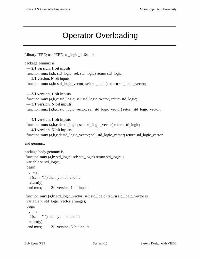
Operator Overloading
Library IEEE; use IEEE.std_logic_1164.all;
package genmux is –– 2/1 version, 1 bit inputs function mux (a,b: std_logic; sel: std_logic) return std_logic; –– 2/1 version, N bit inputs function mux (a,b: std_logic_vector; sel: std_logic) return std_logic_vector;
–– 3/1 version, 1 bit inputs function mux (a,b,c: std_logic; sel: std_logic_vector) return std_logic; –– 3/1 version, N bit inputs function mux (a,b,c: std_logic_vector; sel: std_logic_vector) return std_logic_vector;
–– 4/1 version, 1 bit inputs function mux (a,b,c,d: std_logic; sel: std_logic_vector) return std_logic; –– 4/1 version, N bit inputs function mux (a,b,c,d: std_logic_vector; sel: std_logic_vector) return std_logic_vector;
end genmux;
package body genmux is function mux (a,b: std_logic; sel: std_logic) return std_logic is variable y: std_logic; begin y := a; if (sel = ’1’) then y := b; end if; return(y); end mux; –– 2/1 version, 1 bit inputs
function mux (a,b: std_logic_vector; sel: std_logic) return std_logic_vector is variable y: std_logic_vector(a’range); begin y := a; if (sel = ’1’) then y := b; end if; return(y); end mux; –– 2/1 version, N bit inputs
Mississippi State UniversityElectrical & Computer Engineering
System Design with VHDLSystem–16 Bob Reese 5/95
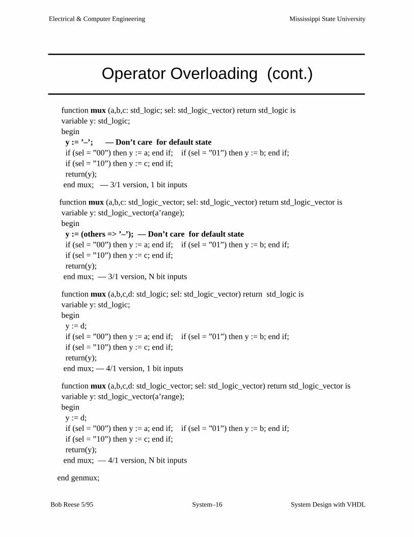
Operator Overloading (cont.)
function mux (a,b,c: std_logic; sel: std_logic_vector) return std_logic is variable y: std_logic; begin y := ’–’; –– Don’t care for default state if (sel = ”00”) then y := a; end if; if (sel = ”01”) then y := b; end if; if (sel = ”10”) then y := c; end if; return(y); end mux; –– 3/1 version, 1 bit inputs
function mux (a,b,c: std_logic_vector; sel: std_logic_vector) return std_logic_vector is variable y: std_logic_vector(a’range); begin y := (others => ’–’); –– Don’t care for default state if (sel = ”00”) then y := a; end if; if (sel = ”01”) then y := b; end if; if (sel = ”10”) then y := c; end if; return(y); end mux; –– 3/1 version, N bit inputs
function mux (a,b,c,d: std_logic; sel: std_logic_vector) return std_logic is variable y: std_logic; begin y := d; if (sel = ”00”) then y := a; end if; if (sel = ”01”) then y := b; end if; if (sel = ”10”) then y := c; end if; return(y); end mux; –– 4/1 version, 1 bit inputs
function mux (a,b,c,d: std_logic_vector; sel: std_logic_vector) return std_logic_vector is variable y: std_logic_vector(a’range); begin y := d; if (sel = ”00”) then y := a; end if; if (sel = ”01”) then y := b; end if; if (sel = ”10”) then y := c; end if; return(y); end mux; –– 4/1 version, N bit inputs
end genmux;

Mississippi State UniversityElectrical & Computer Engineering
System Design with VHDLSystem–17 Bob Reese 5/95
Test of ’mux’ Function
Library IEEE;use IEEE.std_logic_1164.all;use work.genmux.all;
entity muxtest isport ( signal a,b,c: in std_logic; signal s_a: in std_logic_vector(1 downto 0); signal y: out std_logic; signal j,k,l: in std_logic_vector(3 downto 0); signal s_b: in std_logic_vector(1 downto 0); signal z: out std_logic_vector(3 downto 0)); end muxtest;
architecture behavior of muxtest is
begin
y <= mux (a,b,c,s_a); z <= mux (j,k,l,s_b); end behavior;
The mux operator is overloaded; thecorrect mux function is chosen bydoing template matching on the pa-rameter lists.
Mississippi State UniversityElectrical & Computer Engineering
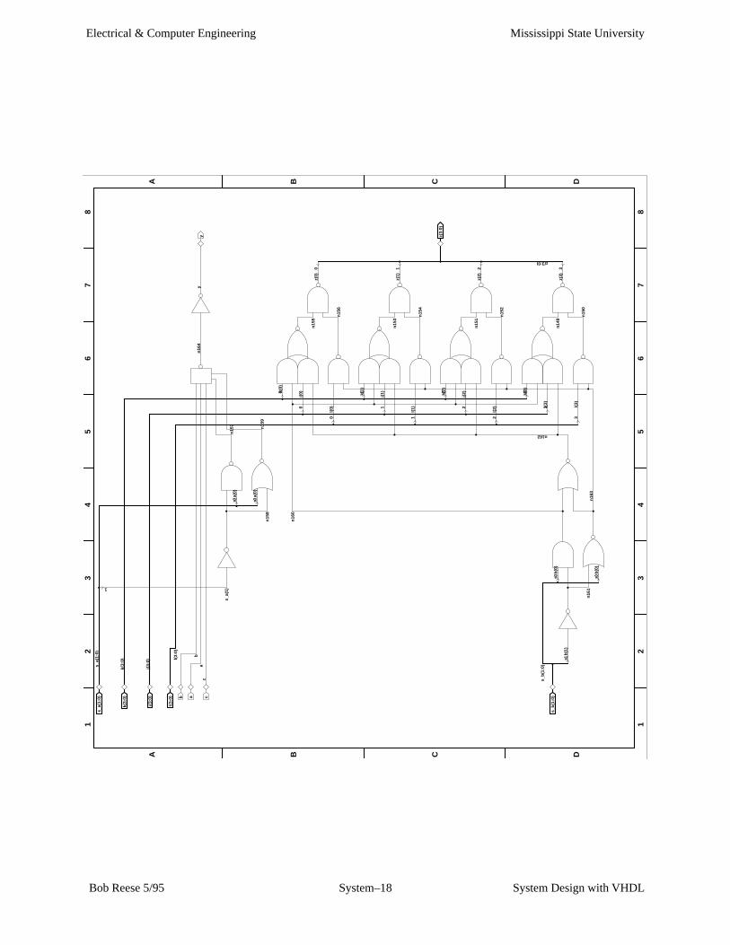
System Design with VHDLSystem–18 Bob Reese 5/95
12
34
56
78
12
34
56
78
A B C D
A B C D
3210
1
0 0
1
0 0
310 2
1 20 3
3210
s_a(
1:0)
s_a(
1:0)
k(3:
0)k(
3:0)
j(3:
0)j(
3:0)
l(3:
0)l(
3:0)
b ab
an
164
yy
cc
s_a(
1)n
157
s_a(
0)
s_a(
0)
n15
9n
158
k(0)
n16
0
j(0)
n15
5z(
0)
l(0)
n15
6
k(1)
j(1)
n15
3z(
1)
l(1)
n15
4
z(3:
0)k(
2)
j(2)
n15
1z(
2)
l(2)
n15
2
k(3)
s_b
(1:0
)
n162
z(3:0)
j(3)
s_b
(1:0
)s_
b(0
)n
149
z(3)
s_b
(1)
l(3)
n15
0n
161
n16
3s_
b(0
)
Mississippi State UniversityElectrical & Computer Engineering
System Design with VHDLSystem–19 Bob Reese 5/95
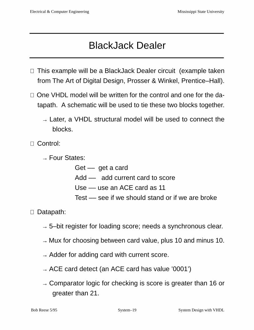
BlackJack Dealer
⇒ This example will be a BlackJack Dealer circuit (example taken
from The Art of Digital Design, Prosser & Winkel, Prentice–Hall).
⇒ One VHDL model will be written for the control and one for the da-
tapath. A schematic will be used to tie these two blocks together.
→ Later, a VHDL structural model will be used to connect the
blocks.
⇒ Control:
→ Four States:
Get –– get a card
Add –– add current card to score
Use –– use an ACE card as 11
Test –– see if we should stand or if we are broke
⇒ Datapath:
→ 5–bit register for loading score; needs a synchronous clear.
→ Mux for choosing between card value, plus 10 and minus 10.
→ Adder for adding card with current score.
→ ACE card detect (an ACE card has value ’0001’)
→ Comparator logic for checking is score is greater than 16 or
greater than 21.
Mississippi State UniversityElectrical & Computer Engineering
System Design with VHDLSystem–20 Bob Reese 5/95
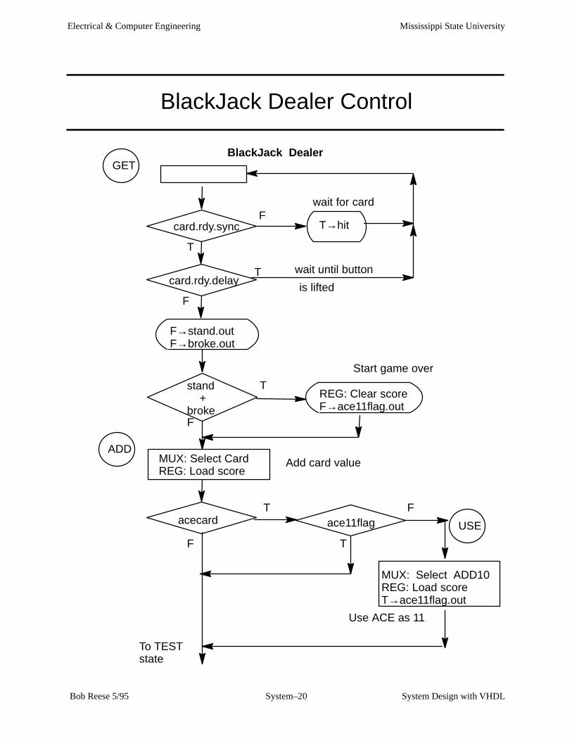
BlackJack Dealer Control
GET
card.rdy.sync
MUX: Select Card REG: Load score
T→hit
ADD
BlackJack Dealer
F
card.rdy.delay
F
F→stand.outF→broke.out
REG: Clear scoreF→ace11flag.out
acecard ace11flag USE
MUX: Select ADD10REG: Load scoreT→ace11flag.out
T
T
T
F
stand +broke
T
T
F
F
To TEST state
Use ACE as 11
Start game over
Add card value
wait for card
wait until button
is lifted
Mississippi State UniversityElectrical & Computer Engineering
System Design with VHDLSystem–21 Bob Reese 5/95
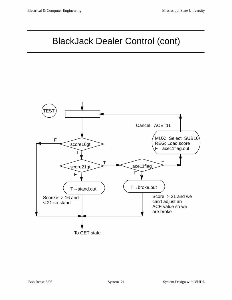
BlackJack Dealer Control (cont)
TEST
score16gt
score21gt
F
T→stand.out
T
Tace11flag
MUX: Select SUB10REG: Load scoreF→ace11flag.out
F
T→broke.out
F
T
T
To GET state
Cancel ACE=11
Score is > 16 and< 21 so stand
Score > 21 and wecan’t adjust anACE value so weare broke

Mississippi State UniversityElectrical & Computer Engineering
System Design with VHDLSystem–22 Bob Reese 5/95
BlackJack DatapathC
ard
Sw
itche
s MUX
5+10
5–10
54
Ace Finderacecard
2
sel
ADDER Score
REG
clear
5
5
5
5
5
Comparatorscore16gt
score21gtMiscellanous Flip Flops to be included in Control
stand.out stand
broke.out broke
ace11flag.outace11flag
CardRdy button
card.rdy.sync
card.rdy.delay
score
load
Mississippi State UniversityElectrical & Computer Engineering
System Design with VHDLSystem–23 Bob Reese 5/95
VHDL File for BlackJack Datapath
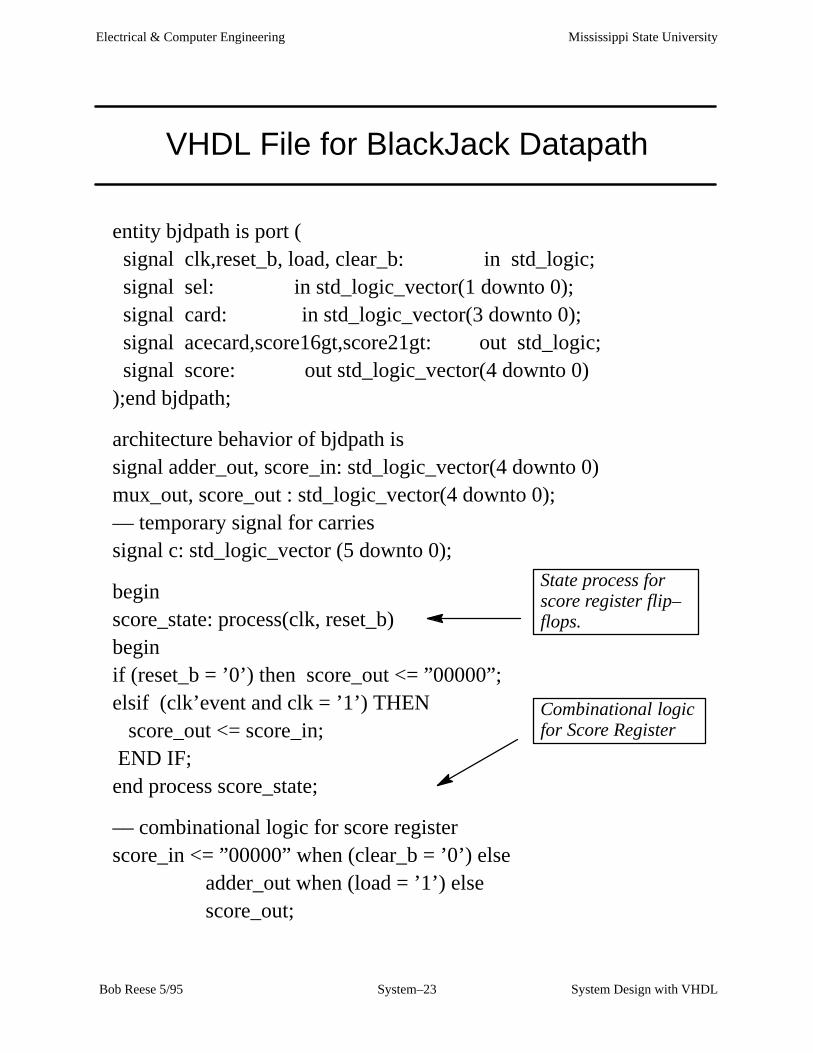
entity bjdpath is port ( signal clk,reset_b, load, clear_b: in std_logic; signal sel: in std_logic_vector(1 downto 0); signal card: in std_logic_vector(3 downto 0); signal acecard,score16gt,score21gt: out std_logic; signal score: out std_logic_vector(4 downto 0));end bjdpath;
architecture behavior of bjdpath issignal adder_out, score_in: std_logic_vector(4 downto 0)mux_out, score_out : std_logic_vector(4 downto 0);–– temporary signal for carriessignal c: std_logic_vector (5 downto 0);
beginscore_state: process(clk, reset_b)beginif (reset_b = ’0’) then score_out <= ”00000”;elsif (clk’event and clk = ’1’) THEN score_out <= score_in; END IF;end process score_state;
–– combinational logic for score registerscore_in <= ”00000” when (clear_b = ’0’) else
adder_out when (load = ’1’) else score_out;
State process forscore register flip–flops.
Combinational logicfor Score Register

Mississippi State UniversityElectrical & Computer Engineering
System Design with VHDLSystem–24 Bob Reese 5/95
VHDL File for BlackJack Datapath (cont.)
–– adder process–– adder_out <= score_out + mux_outadder:process (score_out, mux_out) begin c(0) <= ’0’; for i in score_out’range loop adder_out(i) <= score_out(i) xor mux_out(i) xor c(i); c(i+1) <= (score_out(i) and mux_out(i)) or
(c(i) and (score_out(i) or mux_out(i))); end loop;end process adder;
mux_out <= ”01010” when (sel = B”00”) else ”10110” when (sel = B”10”) else ’0’ & card;
acecard <= ’1’ when (card = B”0001”) else ’0’;
score <= score_out;
score16gt <= ’1’ when (score_out > B”10000”) else ’0’;score21gt <= ’1’ when (score_out > B”10101”) else ’0’; end behavior;
MUX forcard, plus 10,minus 10.
ADDER process
Ace Finder
Comparators

Mississippi State UniversityElectrical & Computer Engineering
System Design with VHDLSystem–25 Bob Reese 5/95
VHDL File for BlackJack Control
entity bjcontrol is port ( signal clk, reset_b, card_rdy, acecard: in std_logic; signal score16gt, score21gt: in std_logic; signal hit, broke, stand: out std_logic; signal sel: out std_logic_vector(1 downto 0); signal score_clear_b, score_load: out std_logic); end bjcontrol;
architecture behavior of bjcontrol is
–– declare internal signals here signal n_state, p_state : std_logic_vector(1 downto 0);signal ace11flag_pstate, ace11flag_nstate: std_logic;signal broke_pstate, broke_nstate: std_logic;signal stand_pstate, stand_nstate: std_logic;signal card_rdy_dly, card_rdy_sync: std_logic;
–– state assignments are as followsconstant get_state: std_logic_vector(1 downto 0) := B”00”;constant add_state: std_logic_vector(1 downto 0) := B”01”;constant test_state: std_logic_vector(1 downto 0) := B”10”;constant use_state: std_logic_vector(1 downto 0) := B”11”;
constant add_10_plus: std_logic_vector(1 downto 0) := B”00”;constant add_card: std_logic_vector(1 downto 0) := B”01”;constant add_10_minus: std_logic_vector(1 downto 0) := B”10”;
Entity declarationand State Assignments

Mississippi State UniversityElectrical & Computer Engineering
System Design with VHDLSystem–26 Bob Reese 5/95
VHDL File for BlackJack Control (cont.)
begin –– state process to implement flag flip–flops and FSM statestate: process(clk, reset_b)beginif (reset_b = ’0’) then p_state <= ”00”;elsif (clk’event and clk = ’1’) THEN p_state <= n_state; ace11flag_pstate <= ace11flag_nstate; broke_pstate <= broke_nstate; stand_pstate <= stand_nstate; card_rdy_dly <= card_rdy_sync; card_rdy_sync <= card_rdy; END IF;end process state;
broke <= broke_pstate;stand <= stand_pstate;
State process to define flip–flops for various flags andfinite state machine .

Mississippi State UniversityElectrical & Computer Engineering
System Design with VHDLSystem–27 Bob Reese 5/95
VHDL File for BlackJack Control (cont.)
comb: process (p_state, ace11flag_pstate, broke_pstate, stand_pstate, acecard, card_rdy_dly, card_rdy_sync, score16gt, score21gt)
beginsel <= B”00”;score_load <= ’0’; score_clear_b <= ’1’;hit <= ’0’; n_state <= p_state;ace11flag_nstate <= ace11flag_pstate;stand_nstate <= stand_pstate; broke_nstate <= broke_pstate;
case p_state is when get_state =>
if (card_rdy_sync = ’0’) then hit <= ’1’; elsif (card_rdy_dly = ’0’) then
stand_nstate <= ’0’; broke_nstate <= ’0’; if (stand_pstate = ’1’ or broke_pstate = ’1’) then score_clear_b <= ’0’; ace11flag_nstate <= ’0’; end if; n_state <= add_state;end if;
when add_state =>sel <= add_card; score_load <= ’1’;if (acecard = ’1’ and ace11flag_pstate = ’0’) then n_state <= use_state;else n_state <= test_state;end if;
’get’ and ’add’states
Mississippi State UniversityElectrical & Computer Engineering
System Design with VHDLSystem–28 Bob Reese 5/95
VHDL File for BlackJack Control (cont.)
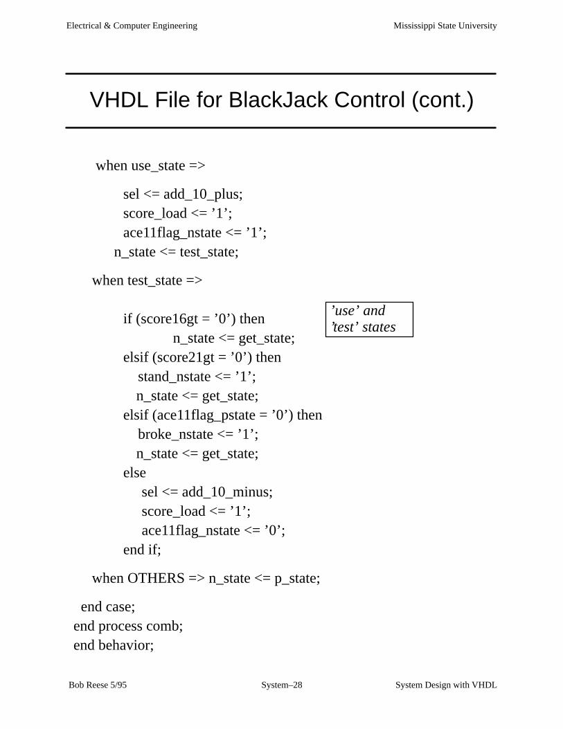
when use_state =>
sel <= add_10_plus;score_load <= ’1’;ace11flag_nstate <= ’1’;
n_state <= test_state;
when test_state =>
if (score16gt = ’0’) then n_state <= get_state;
elsif (score21gt = ’0’) then stand_nstate <= ’1’;
n_state <= get_state;elsif (ace11flag_pstate = ’0’) then broke_nstate <= ’1’;
n_state <= get_state;else sel <= add_10_minus; score_load <= ’1’; ace11flag_nstate <= ’0’;end if;
when OTHERS => n_state <= p_state;
end case;end process comb;end behavior;
’use’ and’test’ states

Mississippi State UniversityElectrical & Computer Engineering
System Design with VHDLSystem–29 Bob Reese 5/95
Top Level Schematic for Dealer

Mississippi State UniversityElectrical & Computer Engineering
System Design with VHDLSystem–30 Bob Reese 5/95
Blackjack Dealer Simulation
Initial Scoreof zero
Enter ’5’ Card Enter ’8’ Card Enter ’4’ Card
Score = 5 + 0 = 5
Score = 8 + 5 = 13
Score = 13 + 4 = 17; score is > 16 so we STAND.
Mississippi State UniversityElectrical & Computer Engineering
System Design with VHDLSystem–31 Bob Reese 5/95
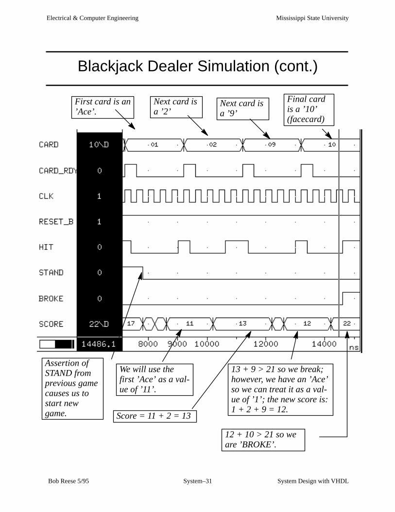
Blackjack Dealer Simulation (cont.)
Assertion ofSTAND fromprevious gamecauses us tostart newgame.
First card is an’Ace’.
Next card is a ’2’
Next card is a ’9’
We will use thefirst ’Ace’ as a val-ue of ’11’.
Score = 11 + 2 = 13
13 + 9 > 21 so we break;however, we have an ’Ace’so we can treat it as a val-ue of ’1’; the new score is:1 + 2 + 9 = 12.
Final cardis a ’10’(facecard)
12 + 10 > 21 so weare ’BROKE’.
Mississippi State UniversityElectrical & Computer Engineering
System Design with VHDLSystem–32 Bob Reese 5/95
Structural VHDL
⇒ You do not have to use a schematic to connect VHDL blocks. You
can write a structural VHDL model which ties the blocks together.
⇒ Pros:
→ When you synthesize the design all of the VHDL blocks are
flattened (collapsed into one block) and it is possible that the
resulting logic may be more efficient.
→ The structural VHDL code is more portable to other design
systems than a schematic.
⇒ Cons:
→ Writing structural VHDL code can be more error prone than
creating a schematic (very easy to misplace a net when you
don’t have a ’picture’ to go by).
→ The resulting flattened netlist can be more difficult to debug.

Mississippi State UniversityElectrical & Computer Engineering
System Design with VHDLSystem–33 Bob Reese 5/95
Structural VHDL for BlackJack Player
entity bj_struct is port ( signal reset_b, clk, card_rdy : in std_logic; signal card: in std_logic_vector(3 downto 0); signal stand, broke,hit: out std_logic; signal score: out std_logic_vector(4 downto 0) );end bj_struct;
architecture structure of bj_struct is component bjcontrol port ( signal clk,reset_b: in std_logic; signal card_rdy, acecard: in std_logic; signal score16gt, score21gt: in std_logic; signal hit, broke,stand: out std_logic; signal sel: out std_logic_vector(1 downto 0); signal score_clear_b: out std_logic; signal score_load: out std_logic ); end component;
component bjdpath port ( signal clk, reset_b: in std_logic; signal load, clear_b: in std_logic; signal sel: in std_logic_vector(1 downto 0); signal card: in std_logic_vector(3 downto 0); signal acecard, score16gt: out std_logic; signal score21gt: out std_logic; signal score: out std_logic_vector(4 downto 0) );
end component;
Need a component dec-laration for each differ-ent type of componentused in the schematic
Normal entitydeclaration.

Mississippi State UniversityElectrical & Computer Engineering
System Design with VHDLSystem–34 Bob Reese 5/95
Structural VHDL for BlackJack Player (cont)
signal load_net, clear_net, acecard_net : std_logic; signal sel_net : std_logic_vector (1 downto 0); signal s21gt_net, s16gt_net: std_logic;
begin c1: bjcontrol port map ( clk => clk,
reset_b => reset_b,card_rdy => card_rdy, acecard => acecard_net,score16gt => s16gt_net,score21gt => s21gt_net,hit => hit, broke => broke, stand => stand,sel => sel_net,score_clear_b => clear_net,score_load => load_net);
c2: bjdpath port map ( clk => clk,
reset_b => reset_b,load => load_net,clear_b => clear_net,
sel => sel_net, card => card, acecard => acecard_net,
score16gt => s16gt_net,score21gt => s21gt_net,
score => score );
end structure;
Internal signal declara-tion for those nets notconnected to externalports.
Each component used in thedesign is given along withits port map.
’c1’ is the component label,’bjcontrol’ gives the compo-nent type.
Only two components inthis design.
Mississippi State UniversityElectrical & Computer Engineering
System Design with VHDLSystem–35 Bob Reese 5/95
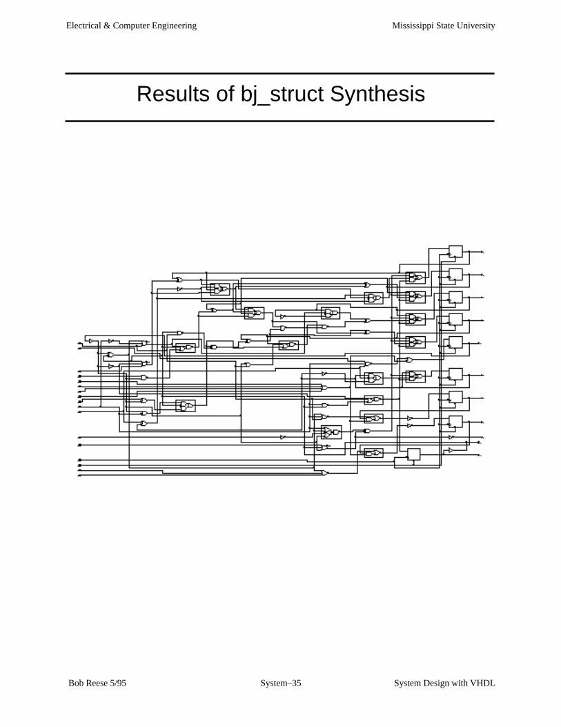
Results of bj_struct Synthesis