LOGIC CONTROL OWNER'S MANUAL - LiftMaster · OWNER'S MANUAL MODELS: J H HJ SOLID STATE INDUSTRIAL...
24
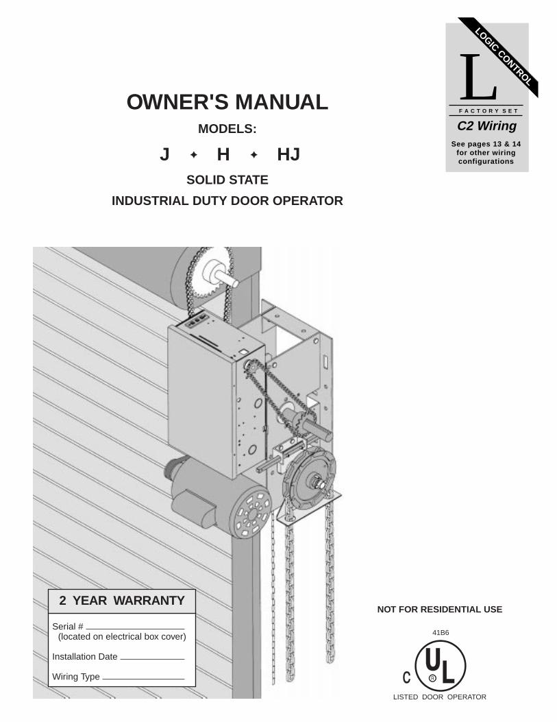
OWNER'S MANUAL MODELS: J ✦ H ✦ HJ SOLID STATE INDUSTRIAL DUTY DOOR OPERATOR LOGIC CONTROL L C2 Wiring F A C T O R Y SET See pages 13 & 14 for other wiring configurations NOT FOR RESIDENTIAL USE LISTED DOOR OPERATOR 41B6 Serial # (located on electrical box cover) Installation Date Wiring Type 2 YEAR WARRANTY
Transcript of LOGIC CONTROL OWNER'S MANUAL - LiftMaster · OWNER'S MANUAL MODELS: J H HJ SOLID STATE INDUSTRIAL...
OWNER'S MANUALMODELS:
J ✦✦ H ✦✦ HJSOLID STATE
INDUSTRIAL DUTY DOOR OPERATOR
LOGIC CONTROLLC2 WiringF A C T O R Y S E T
See pages 13 & 14for other wiringconfigurations
NOT FOR RESIDENTIAL USE
LISTED DOOR OPERATOR
41B6Serial #
(located on electrical box cover)
Installation Date
Wiring Type
2 YEAR WARRANTY

2
MOTORTYPE: .................................Continuous duty
HORSEPOWER: .................1/3, 1/2, 3/4 & 1 HpSingle or Three phase
SPEED: ...............................1725 RPM
VOLTAGE: ..........................115, 220, 230 Singlephase208, 230, 460, 575 Threephase
CURRENT: .........................See motor nameplate
MECHANICALDRIVE REDUCTION:...Primary: Heavy duty (5L) V-Belt.Secondary: #48 chain/sprocket Output: #50 chain
OUTPUT SHAFT SPEED: .....36 R.P.M.
DOOR SPEED: ......................6 - 7” per sec.depending on door
BRAKE: (Optional) ...............Solenoid actuated discbrake
BEARINGS: ...........................Output Shaft: Shielded Ball Bearing. Clutch Shaft: IronCopper sintered andoil impregnated.
HAND CHAIN WHEEL: .........Left or right handingModels H and HJ only.
SAFETYDISCONNECT :
Model J : Floor level disconnect for emergency manual door operation.
Model H: Floor level chain hoist with electrical interlock for emergency manual door operation.
Model HJ: Includes both floor level disconnect systems stated above.
REVERSING EDGE: ......(Optional) Electric or pneumaticsensing device attached to the bottom edge of door.
A REVERSING EDGE IS STRONGLYRECOMMENDED FOR ALL COMMERCIALOPERATOR INSTALLATIONS. REQUIRED WHENTHE 3 BUTTON CONTROL STATION IS OUT OFSIGHT OF DOOR OR ANY OTHER CONTROL(AUTOMATIC OR MANUAL) IS USED.
SPECIFICATIONS
ELECTRICALTRANSFORMER: .............24VAC
CONTROL STATION: ......NEMA 1 three button station.OPEN/CLOSE/STOP
WIRING TYPE: .................C2 (Factory Shipped) Momentary contact to OPEN & STOP, constantpressure to CLOSE, open override plus wiring forsensing device to reverse. See pages 13 and 14 foroptional control settings and operating modes.
LIMIT ADJUST: ................Linear driven, fully adjustable screw type cams. Adjustable to 24 feet.
20.91”
7.50”
5.50”
6.63”
13.75”
1.50”
4.75”
4.41”
4.63
13.00”
16.50”
14.50”
7.25”
8.00” 7.50”
AA
AA
BB
BB
MOUNTING DIMENSIONSA - Wall MountingB - Bracket Mounting (rolling door)
WEIGHTS AND DIMENSIONSHANGING WEIGHT: .........80-110 LBS.
Hand Chain Wheelpresent with ModelsH and HJ only.

3
2-1/4"
FIGURE 1
Shaft Support Bracketwith Bearing (Not Supplied)Door Sprocket
TO AVOID DAMAGE TO DOOR AND OPERATOR,MAKE ALL DOOR LOCKS INOPERATIVE. SECURELOCK(S) IN "OPEN" POSITION.IF THE DOOR LOCK NEEDS TO REMAINFUNCTIONAL, INSTALL AN INTERLOCK SWITCH. DO NOT CONNECT ELECTRIC POWER UNTILINSTRUCTED TO DO SO.
KEEP DOOR BALANCED. STICKING OR BINDINGDOORS MUST BE REPAIRED. DOORS, DOORSPRINGS, CABLES, PULLEYS, BRACKETS ANDTHEIR HARDWARE MAY BE UNDER EXTREMETENSION AND CAN CAUSE SERIOUS PERSONALINJURY. CALL A PROFESSIONAL DOORSERVICEMAN TO MOVE OR ADJUST DOORSPRINGS OR HARDWARE.
CAUTIONCAUTION WARNING
SITE PREPARATIONSIt is imperative that the wall or mounting surfaceprovide adequate support for the operator.This surface must:
a) Be rigid to prevent play between operator and door shaft.
b) Provide a level base.c) Permit the operator to be fastened securely and
with the drive shaft parallel to the door shaft.
The safety and wear of the operator will be adverselyaffected if any of the above requirements are not met.
For metal buildings, fasten 2” x 2” x 3/16” (or larger)angle iron frames to the building purlins. Retain5-1/2” between frames. See Figure 1.
Both J and H series operators have dual output shafts and may be mounted on either the right (standard) or leftside of door, and in either a vertical (standard) or horizontal mounting position. If you need to move the drivesprocket, loosen BOTH set screws, remove the sprocket and key, and place on the opposite side of the driveshaft. Be sure to tighten BOTH set screws securely
OPERATOR PREPARATION
Hand Chain HandingFor models H and HJ with manual hoist hand chain systems, the handing of the operator must be determined atthe time of order. The handing is indicated by last letter of the model name (R or L). The hand chain wheel cannot be switched on site. If your installation causes the hand chain to hang in the door opening, hook the chainoff to the side near the top of the door jamb.
IMPORTANT SAFETY NOTES
Output Shaft Key
Drive Sprocket
(2) Set Screws
5-1/2”

4
1a. Wall MountingThe operator should generally be installed belowthe door shaft, and as close to the door aspossible. The optimum distance between the doorshaft and operator drive shaft is between 12” - 15”.Refer to Figure 3.
OPERATOR MOUNTING
IMPORTANT: The shelf or bracket mustprovide adequate support, prevent playbetween operator and door shaft, and permitoperator to be fastened securely and with thedrive shaft parallel to the door shaft.
1b. Bracket or Shelf Mounting The operator may be mounted either above orbelow the door shaft. The optimum distancebetween the door shaft and operator drive shaft isbetween 12” - 15”. Refer to Figure 4.
1c. Place door sprocket on the door shaft. Do notinsert the key at this time.
2. Place drive sprocket on the appropriate side ofthe operator. Do not insert the key at this time.
3. Wrap drive chain around door sprocket and joinroller chain ends together with master link.
4. Raise operator to approximate mounting positionand position chain over operator sprocket.
5. Raise or lower operator until the chain is taut (nottight). Make sure the operator output shaft isparallel to door shaft and sprockets are aligned.When in position, secure the operator to wall ormounting bracket.
6. Align sprockets and secure, (see Figure 5).
FIGURE 4FIGURE 3
Before your operator is installed, be sure the door has been properly aligned and is working smoothly. Theoperator may be wall mounted or mounted on a bracket or shelf. If necessary, refer to the operator preparationson page 3. Refer to the illustration and instructions below that suits your application.
Typical Right HandWall Mounted Operator
Optimum Distance12 - 15”
Optimum Distance12 - 15”
OPTIONALMounting BracketP/N 08-9098
Be sure doorsprocket is properlyaligned with drivebefore securing tothe shaft.
Chain Keeper
FIGURE 5
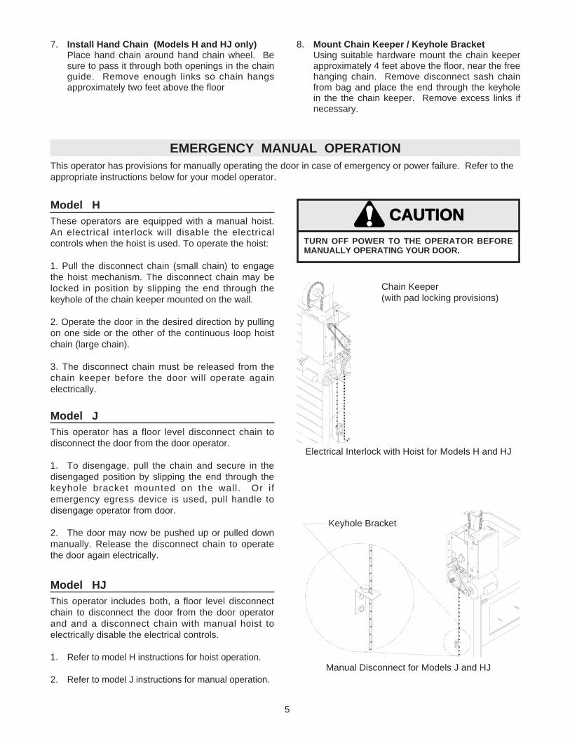
These operators are equipped with a manual hoist.An electrical interlock will disable the electricalcontrols when the hoist is used. To operate the hoist:
1. Pull the disconnect chain (small chain) to engagethe hoist mechanism. The disconnect chain may belocked in position by slipping the end through thekeyhole of the chain keeper mounted on the wall.
2. Operate the door in the desired direction by pullingon one side or the other of the continuous loop hoistchain (large chain).
3. The disconnect chain must be released from thechain keeper before the door will operate againelectrically.
5
7. Install Hand Chain (Models H and HJ only)Place hand chain around hand chain wheel. Besure to pass it through both openings in the chainguide. Remove enough links so chain hangsapproximately two feet above the floor
EMERGENCY MANUAL OPERATIONThis operator has provisions for manually operating the door in case of emergency or power failure. Refer to theappropriate instructions below for your model operator.
Model H
Model JThis operator has a floor level disconnect chain todisconnect the door from the door operator.
1. To disengage, pull the chain and secure in thedisengaged position by slipping the end through thekeyhole bracket mounted on the wall. Or ifemergency egress device is used, pull handle todisengage operator from door.
2. The door may now be pushed up or pulled downmanually. Release the disconnect chain to operatethe door again electrically.
Chain Keeper(with pad locking provisions)
Keyhole Bracket
8. Mount Chain Keeper / Keyhole BracketUsing suitable hardware mount the chain keeperapproximately 4 feet above the floor, near the freehanging chain. Remove disconnect sash chainfrom bag and place the end through the keyholein the the chain keeper. Remove excess links ifnecessary.
Model HJThis operator includes both, a floor level disconnectchain to disconnect the door from the door operatorand and a disconnect chain with manual hoist toelectrically disable the electrical controls.
1. Refer to model H instructions for hoist operation.
2. Refer to model J instructions for manual operation.Manual Disconnect for Models J and HJ
Electrical Interlock with Hoist for Models H and HJ
TURN OFF POWER TO THE OPERATOR BEFOREMANUALLY OPERATING YOUR DOOR.
CAUTIONCAUTION

6
TO AVOID SERIOUS PERSONAL INJURY OR DEATHFROM ELECTROCUTION, DISCONNECT ELECTRICPOWER BEFORE MANUALLY MOVING LIMIT NUTS.
WARNING
LIMIT SWITCH ADJUSTMENTMAKE SURE THE LIMIT NUTS ARE POSITIONED BETWEEN THE LIMIT SWITCH ACTUATORS BEFOREPROCEEDING WITH ADJUSTMENTS.
SENSING EDGESAll types of sensing edges with an isolated normallyopen (N.O.) output are compatible with youroperator. This includes pneumatic and electricedges. If your door does not have a bottom sensingedge and you wish to purchase one, contact thesupplier of your operator.
If not pre-installed by the door manufacturer, mountthe sensing edge on the door according to theinstructions provided with the edge. The sensingedge may be electrically connected by either coiledcord or take-up reel. Refer to the steps below.
Important Notes:a) Proceed with Limit Switch Adjustments before
making any sensing edge wiring connections tooperator as described below.
b) Electrician must hardwire the junction box to theoperator electrical box in accordance with localcodes.
ENTRAPMENT PROTECTION ACCESSORIES (OPTIONAL)
IT IS STRONGLY RECOMMENDED THAT ASENSING EDGE OR OTHER ENTRAPMENTPROTECTION DEVICE BE USED INCONJUNCTION WITH THIS OPERATOR.
TAKE-UP REEL: Take-up reel should be installed12" above the top of the door.
COIL CORD: Connect operator end of coil cord tojunction box (not supplied) fastened to the wallapproximately halfway up the door opening.
If other problems persist, call our toll-free number forassistance - 1-800-528-2806.
1. To adjust limit nuts depress retaining plate to allownut to spin freely. After adjustment, release plateand ensure it seats fully in slots of both nuts.
2. To increase door travel, spin nut away fromactuator. To decrease door travel, spin limit nuttoward actuator.
3. Adjust open limit nut so that door will stop in openposition with the bottom of the door even with topof door opening.
4. Repeat Steps 1 and 2 for close cycle. Adjust closelimit nut so that actuator is engaged as door fullyseats at the floor.
Retaining Plate
CLOSE Limit Switch
SAFETY(Aux. Close) Limit Switch
OPEN Limit Switch
Actuator
Aux. OPEN Limit Switch

7
W A R N I N GTO PREVENT ENTRAPMENT
DO NOT START DOOR DOWNWARD
UNLESS DOORWAY IS CLEAR
OPEN
CLOSE
STOP
Control Station
WARNING Notice
PushButtons
WARNINGDISCONNECT POWER AT THE FUSE BOX BEFOREPROCEEDING.OPERATOR MUST BE PROPERLY GROUNDED ANDCONNECTED IN ACCORDANCE WITH LOCALELECTRICAL CODES. NOTE: THE OPERATORSHOULD BE ON A SEPARATE FUSED LINE OFADEQUATE CAPACITY.ALL ELECTRICAL CONNECTIONS MUST BE MADEBY A QUALIFIED INDIVIDUAL.
WARNINGTO AVOID DAMAGE TO DOOR AND OPERATOR,MAKE ALL DOOR LOCKS INOPERATIVE. SECURELOCK(S) IN "OPEN" POSITION.IF THE DOOR LOCK NEEDS TO REMAINFUNCTIONAL, INSTALL AN INTERLOCK SWITCH.
WARNINGINSTALL THE CONTROL STATION WHERE THEDOOR IS VISIBLE, BUT AWAY FROM THE DOOR ANDITS HARDWARE. IF CONTROL STATION CANNOT BEINSTALLED WHERE DOOR IS VISIBLE, OR IF ANYDEVICE OTHER THAN THE CONTROL STATION ISUSED TO ACTIVATE THE DOOR, A REVERSINGEDGE MUST BE INSTALLED ON THE BOTTOM OFTHE DOOR. FAILURE TO INSTALL A REVERSINGEDGE UNDER THESE CIRCUMSTANCES MAYRESULT IN SERIOUS INJURY OR DEATH TOPERSONS TRAPPED BENEATH THE DOOR.
1. Complete electrical connections to the operatorand the control station. Fasten the control stationto the wall and MOUNT THE WARNING NOTICEBESIDE OR BELOW THE PUSH BUTTONSTATION.
2. Apply power to the operator. Press OPEN pushbutton and observe direction of door travel andthen Press the STOP button.If door did not move in the correct direction,check for improper wiring at the control station orbetween operator and control station.If the operator is three phase and control stationwiring is correct, exchange any two of the threeincoming power leads.If electrical problems persist, call our Toll Freenumber for assistance (1-800-528-2806).
CABLE CONNECTION NOTE:Be sure to use the control box opening with the 7/8” dia. hole for CONTROL cable(s). All power wiresuse the 1-1/16” dia. hole.
Refer to Control Connection Diagrams on pages11 & 13. Make connection through hole labeled forcontrol. Do not run control wires in the sameconduit as power wires.
Before installing control station be sure to follow all warnings described below. Failure to do so mayresult in severe injury to persons and/or damage to operator. Do not install any wiring or attempt to runthe operator without consulting the wiring diagram. Install the optional Reversing Edge before proceedingwith the Control Station installation.
IMPORTANT: Mount WARNING NOTICE beside orbelow the push button station.
IMPORTANT SAFETY NOTES CONTROL STATION WIRING
MOUNT WARNING NOTICE
INSTALL POWER WIRING & CONTROL STATION
1-1/16” dia. PowerWiring Access Hole
7/8” dia. ControlWiring Access Hole(Opposite Side)

8
CLUTCH ADJUSTMENT
1. Remove cotterpin from nut on the clutch shaft.
2. Back off clutch nut until there is very little tensionon the clutch spring.
3. Tighten clutch nut gradually until there is justenough tension to permit the operator to move thedoor smoothly but to allow the clutch to slip if the dooris obstructed. When the clutch is properly adjusted, itshould generally be possible to stop the door by handduring travel.
4. Reinstall Cotterpin.
CAUTION: The adjustable friction clutch is NOTan automatic reversing device. An electric orpneumatic reversing edge can be added tobottom edge of door if desired.
Cotterpin
Adjusting Nut
Spring
Clutch Pulley
Clutch Plate
Clutch Pad
Washer
BRAKE ADJUSTMENT
A solenoid brake is an optional modification. If present, the brake is adjusted at the factory and should not needadditional adjustment for the the life of the friction pad. If desired, a brake can also be field installed. To order akit for field installation on an existing operator, call the parts and service department at 1-800-528-2806.
Replace friction pads when necessary. Refer to theillustration for identification of components for thesolenoid type brake system.
Friction Pads
Release Lever
Plate Assembly
Solenoid
Solenoid Brake System

9
✳✳ Use SAE 30 Oil (Never use grease or silicone spray).
✔✔ Repeat ALL procedures.
■■ Do not lubricate motor. Motor bearings are rated for continuous operation.
■■ Do not lubricate clutch or V-belt.
■■ Inspect and service whenever a malfunction is observed or suspected.
■■ CAUTION: BEFORE SERVICING, ALWAYS DISCONNECT OPERATOR FROM POWER SUPPLY.
Check at the intervals listed in the following chart.
HOW TO ORDER REPAIR PARTSOUR LARGE SERVICE ORGANIZATION
SPANS AMERICAINSTALLATION AND SERVICE INFORMATION
ARE AVAILABLE 6 DAYS A WEEKCALL OUR TOLL FREE NUMBER - 1-800-528-2806
HOURS 7:00 TO 3:30 p.m. (Mountain Std. Time)MONDAY Through SATURDAY
WHEN ORDERING REPAIR PARTSPLEASE SUPPLY THE FOLLOWING INFORMATION:PART NUMBER DESCRIPTION MODEL NUMBER
ADDRESS ORDER TO:THE CHAMBERLAIN GROUP, INC.
Electronic Parts & Service Dept.2301 N. Forbes Blvd., Suite 104
Tucson, AZ 85745
EVERY EVERY EVERYITEM PROCEDURE 3 MONTHS 6 MONTHS 12 MONTHSDrive Chain Check for excessive slack.
Check & adjust as required.Lubricate.* ● ✔
Sprockets Check set screw tightness ●● ✔✔
Clutch Check & adjust as required ●● ✔✔
Belt Check condition & tension ●● ✔✔
Fasteners Check & tighten as required ●● ✔✔
Manual Disconnect Check & Operate ●● ✔✔
Bearings & Shafts Check for wear & lubricate ●● ✔✔
MAINTENANCE SCHEDULE
10
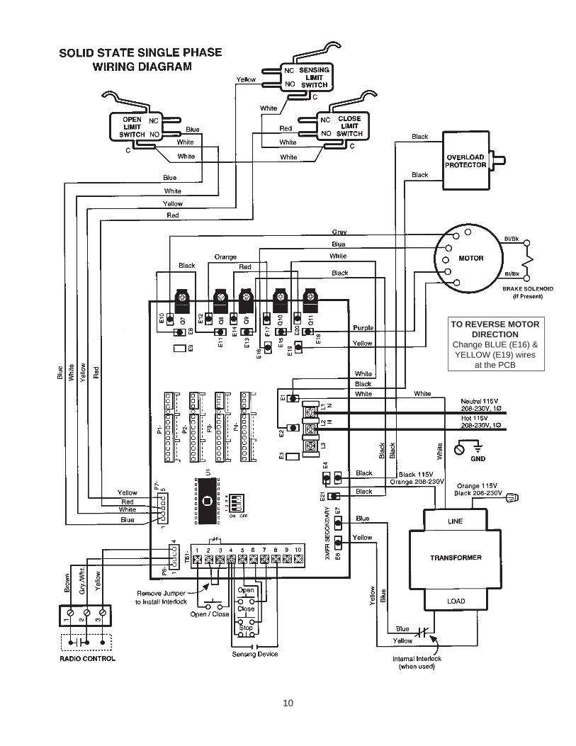
TO REVERSE MOTORDIRECTION
Change BLUE (E16) &YELLOW (E19) wires
at the PCB

STANDARD POWER & CONTROL CONNECTION DIAGRAM
1 2 3 4 5 6 7 8 9 10
L3
L2 H
L1 N
TB1-
1 2 3
Open
Open / Close
Remove Jumperto Install Interlock
RADIO CONTROL(24V dc only)
Stop
Sensing Device
Hot 115V, 208-230V, 1Ø
Neutral 115V, 208-230V, 1Ø
Close GND
1 2 3 4 5 6 7 8 9 10
L3
L2 H
L1 N
TB1-
1 2 3
Open
Open / Close
RADIO CONTROL(24V dc only)
Stop
Sensing Device
208-230V, 3Ø
208-230V, 3Ø
208-230V, 3Ø
Close GND
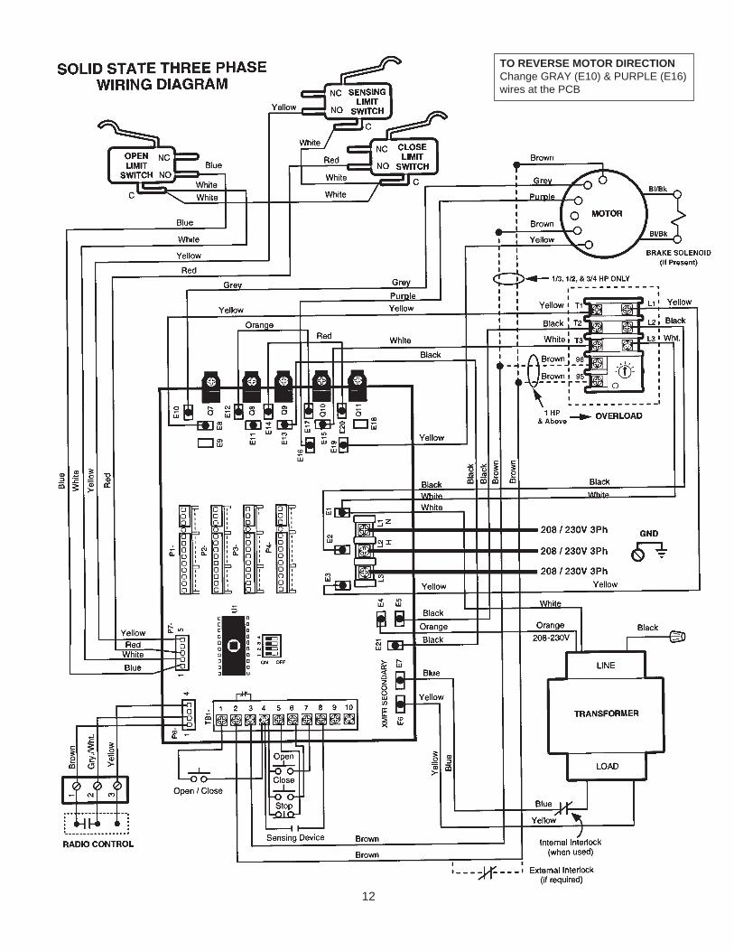
STANDARD POWER & CONTROL CONNECTION DIAGRAM
Solid State Board CDO - 115V, 208-230V, 1Ph
Solid State Board CDO - 208-230V3Ph
11
12
TO REVERSE MOTOR DIRECTIONChange GRAY (E10) & PURPLE (E16)wires at the PCB
13
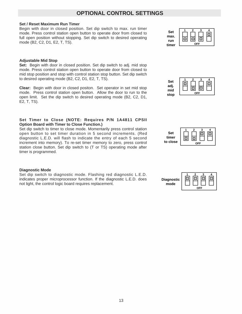
Set / Reset Maximum Run TimerBegin with door in closed position. Set dip switch to max. run timermode. Press control station open button to operate door from closed tofull open position without stopping. Set dip switch to desired operatingmode (B2, C2, D1, E2, T, TS).
Adjustable Mid StopSet: Begin with door in closed position. Set dip switch to adj. mid stopmode. Press control station open button to operate door from closed tomid stop position and stop with control station stop button. Set dip switchto desired operating mode (B2, C2, D1, E2, T, TS).
Clear: Begin with door in closed positon. Set operator in set mid stopmode. Press control station open button. Allow the door to run to theopen limit. Set the dip switch to desired operating mode (B2, C2, D1,E2, T, TS).
Set Timer to Close (NOTE: Requires P/N 1A4811 CPSIIOption Board with Timer to Close Function.)Set dip switch to timer to close mode. Momentarily press control stationopen button to set timer duration in 5 second increments. (Reddiagnostic L.E.D. will flash to indicate the entry of each 5 secondincrement into memory). To re-set timer memory to zero, press controlstation close button. Set dip switch to (T or TS) operating mode aftertimer is programmed.
Diagnostic ModeSet dip switch to diagnostic mode. Flashing red diagnostic L.E.D.indicates proper microprocessor function. If the diagnostic L.E.D. doesnot light, the control logic board requires replacement.
Setmax.run
timer
1 2 3
OFF
4
OPTIONAL CONTROL SETTINGS
Setadj.midstop
1 2 3
OFF
4
Settimer
to close
1 2 3
OFF
4
Diagnosticmode
1 2 3
OFF
4

14
C2
D1
E2
T
TS
B2
1 2 3
OFF
4
1 2 3
OFF
4
1 2 3
OFF
4
1 2 3
OFF
4
1 2 3
OFF
4
1 2 3
OFF
4
TYPE STATION
B2 3 Button, 1 Button, 1 & 3 Button Radio ControlFunction: Momentary contact to open, close and stop, plus wiring forsensing device to reverse and auxiliary devices to open and closewith open override.
C2 3 Button, 3 Button Radio ControlFunction: Momentary contact to open and stop with constant pressureto close, open override plus wiring for sensing device to reverse.
D1 2 Button, 3 Button Radio ControlFunction: Constant pressure to open and close with wiring for sensingdevice to stop.
E2 2 Button, 3 Button Radio ControlFunction: Momentary contact to open with override and constantpressure to close. Release of close button will cause door to reverse(roll-back feature) plus wiring for sensing device to reverse.
T* 3 Button, 1 Button, 1 & 3 Button Radio ControlFunction: Momentary contact to open, close, and stop, with openoverride and timer to close. Every device that causes door to open,except a reversing device, activates timer to close. Auxiliary controlscan be connected to open input to activate the timer to close. If thetimer has been activated, the open button and radio control canrecycle the timer. The stop button will deactivate the timer until theclose button is used to close the door. (NOTE: Requires P/N 1A4811CPSII Option Board with Timer to Close Function.)
TS* 3 Button, 1 Button, 1 & 3 Button Radio ControlFunction: Momentary contact to open, close, and stop with openoverride and timer to close. Every device that causes door to open,including a reversing device, activates timer to close. Auxiliarycontrols can be connected to open input to activate the timer to close.If the timer has been activated, the open button and radio control canrecycle the timer. The stop button will deactivate the timer until theclose button is used to close the door. (NOTE: Requires P/N 1A4811CPSII Option Board with Timer to Close Function.)
NOTE:
1. External interlocks may be used with all functional modes.2. Auxiliary devices are any devices that have only one set of
contacts. Examples are: photocell, loop detector, pneumatic orelectrical treadles, residential radio controls, one button stations,pull cords, etc.
3. Open override means that the door may be reversed while closingby activating an opening device without the need to use the stopbutton first.
OPERATING MODE

15
NEMA MOTOR WIRING DIAGRAMS
SINGLE VOLTA G E1/3 & 1/2HP 1 15V ONLY
1 PHASE
3 PHASE
Motor
Purple
Grey
Blue
Yellow
Cable
T1-Blue
T4-Yellow
T5-Black
T8-Red
Motor
Grey
Blue
Purple
Yellow
Cable
T2-White
T4-Yellow
T5-Black
T8-Red
T3-OrangeT1-Blue
115V
115V
Motor
Blue
Purple
Yellow
Cable
T4-Yellow
T5-Black
T1-Blue
208-230V
T3Orange
T2White
T8Red
Grey
(Not Used)
Motor
Grey
Purple
Yellow
Cable
T1
T2
T6
208-230V
T4
T5
T7
T3
T9
T8
Motor
Grey
Brown
BrownPurple
Yellow
Cable
T1
T2
T6
208-230V
T4
T5
T7
T3
T9
T8
P1
P2
1/3, 1/2 & 3/4 Horsepower 1 Horsepower and above
11
5V
BR
AK
E S
OL
EN
OID
(WH
EN
RE
QU
IRE
D)
BLACK/BLUE
BLACK/BLUE
23
0V
BR
AK
E S
OL
EN
OID
(WH
EN
RE
QU
IRE
D)
BLACK/BLUE
BLACK/BLUE
23
0V
BR
AK
E S
OL
EN
OID
(WH
EN
RE
QU
IRE
D)
BLACK/BLUE
BLACK/BLUE
23
0V
BR
AK
E S
OL
EN
OID
(WH
EN
RE
QU
IRE
D)
BLACK/BLUE
BLACK/BLUE
TO REVERSE MOTOR DIRECTIONChange BLUE (E16) & YELLOW (E19)wires at the PCB
TO REVERSE MOTOR DIRECTIONChange GRAY (E10) & PURPLE (E16)wires at the PCB
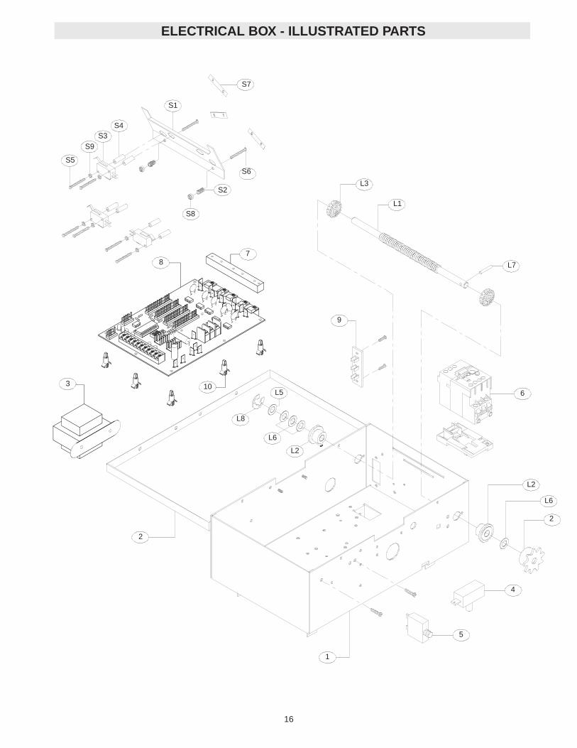
ELECTRICAL BOX - ILLUSTRATED PARTS
16
2
1
5
2
L6
L2
6
L7
L3
L1
9
3 10
78
S8
S2
S6
S1
S4S3
S9
S5
S7
L6
L2
L8
L5
4
17
Qty123662326
ItemS1S2S3S4S5S6S7S8S9
P/N 10-1001318-1003623-1004131-1004382-PX04-1982-PX06-1684-DT-0484-LH-0685-IG-04
DescritionDepress PlateSpring, Depress PlateLimit SwitchStandoff, Limit SwitchScrew, #4-40 x 1-3/8” Pan Head PhScrew, #6-32 x 1” Pan Hd PhilNut, Double TinnermanLocknut, #6-32 Nylon HexLockwasher, #4 Internal Tooth
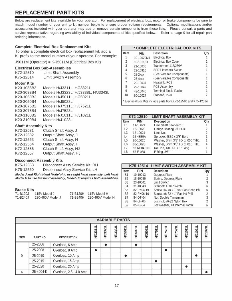
REPLACEMENT PART KITSBelow are replacement kits available for your operator. For replacement of electrical box, motor or brake components be sure tomatch model number of your unit to kit number below to ensure proper voltage requirements. Optional modifications and/oraccessories included with your operator may add or remove certain components from these lists. Please consult a parts andservice representative regarding availability of individual components of kits specified below. Refer to page 9 for all repair partordering information.
Complete Electrical Box Replacement Kits To order a complete electrical box replacement kit, add aK- prefix to the model number of your operator. For example:
J5011M (Operator) = K-J5011M (Electrical Box Kit)
Electrical Box Sub-AssembliesK72-12510 Limit Shaft AssemblyK75-12514 Limit Switch Assembly
Motor KitsK20-1033B2 Models H/J3311L, H/J3321LK20-3033B4 Models H/J3323L, H/J3338L, H/J3343LK20-1050B2 Models H/J5011L, H/J5021LK20-3050B4 Models H/J5023LK20-1075B2 Models H/J7511L, H/J7521LK20-3075B4 Models H/J7523LK20-1100B2 Models H/J1011L, H/J1021LK20-3100B4 Models H/J1023L
Shaft Assembly KitsK72-12531 Clutch Shaft Assy, JK72-12532 Output Shaft Assy, JK72-12563 Clutch Shaft Assy, HK72-12564 Output Shaft Assy, HK72-12556 Clutch Shaft Assy, HJK72-12557 Output Shaft Assy, HJ
Disconnect Assembly KitsK75-12558 Disconnect Assy Service Kit, RHK75-12560 Disconnect Assy Service Kit, LHModel J and RIght Hand Model H to use right hand assembly, Left handModel H to use left hand assembly, Model HJ requires both assemblies
Brake Kits71-B120J 115V Model J 71-B120H 115V Model H71-B240J 230-460V Model J 71-B240H 230-460V Model H
K72-12510 LIMIT SHAFT ASSEMBLY KITItemL1L2L3L4L5L6L7L8
DescriptionLimit Shaft, Standard TFlange Bearing, 3/8” I.D.Limit NutSprocket 48B9 x 3/8” BoreWasher, Shim 3/8” I.D. x .050 THK.Washer, Shim 3/8” I.D. x .010 THK.Roll Pin, 1/8 DIA. x 1” LongE Ring, 3/8”
Qty12211411
K75-12514 LIMIT SWITCH ASSEMBLY KIT
P/N 11-1002112-1002813-1002415-48B9A80-1002580-1002686-RP04-10087-E-038
* COMPLETE ELECTRICAL BOX KITSItem
123456789
10
DescritionElectrical BoxElectrical Box CoverTranformer, 115/230VSPDT Interlock Switch(See Varaible Components)(See Varaible Components)Heatsink, PCBPCB AssemblyTerminal Block, RadioStandoff, PCB
Qty1111111117
P/N 10-10020M110-10115X21-1003823-1091625-2xxx25-4xxx29-1003729-1004242-1004080-10027
* Electrical Box Kits include parts from K72-12510 and K75-12514
ITEM
5
6
VARIABLE PARTS
PART NO.
25-2006
25-2008
25-201025-201525-202025-4004-K
DESCRIPTION
Overload, 6 AmpOverload, 8 AmpOverload, 10 AmpOverload, 15 Amp
Overload, 20 AmpOverload, 2.5 - 4.0 Amp
H/J
3311
L
H/J
3321
L
H/J
3323
L
H/J
5011
L
H/J
5021
L
H/J
5023
L
H/J
7511
L
H/J
7521
L
H/J
7523
L
H/J
1011
L
H/J
1021
L
H/J
1023
L
18
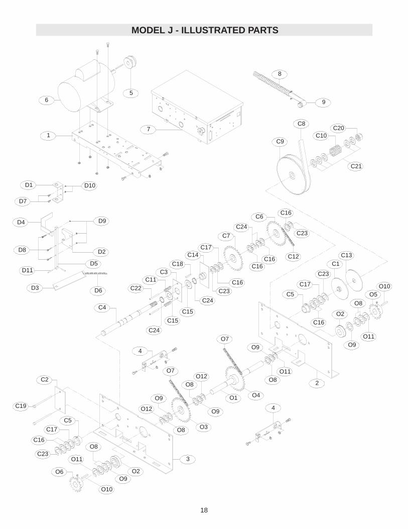
MODEL J - ILLUSTRATED PARTS
C20C10
C9
C8
C21
C16C6
C24
C7
C17
C16C16 C12
C23
C14
C18C3
C11C22
C16
C23
C24
C15
C15
C24
C4
C2
C19
C23
C16
C5
C17
O8
O11
O6 O2O9
O10
O7
O8O12
O4O1
O9
O3O8
O12
O9
O7O9
O11O8
C5
C16
C17
C23
C1C13
O2
O9
O8
O5
O11
O10
D1
D7
D4
D8
D11
D3
D10
D6
D9
D2
D5
7
6
1
5
4
4
3
2
8
9

19
SOLID STATEREPLACEMENT PARTS LIST – MODEL J
Refer to the parts lists below for replacement kits available for your operator. If optional modifications and/oraccessories are included with your operator, certain components may be added or remove from these lists.Individual components of each kit may not be available. Please consult a parts and service representativeregarding availability of individual components. Refer to page 9 for all repair part ordering information.
K72-12531 CLUTCH SHAFT ASSEMBLY KIT
ITEM PART # DESCRIPTION QTY
C1
C2
C3
C4
C5
C6
C7
C8
C9
C10
C11
C12
C13
C14
C15
C16
C17
C18
C19
C20
C21
C22
C23
C24
Clutch Plate
External Disconnect Bracket
Internal Disconnect Plate
Clutch Shaft
1” Flanged Keyed Bearing
48B32/48B14 Idler Sprocket Assy
Compound Sprocket #48B32 x 14
V Belt, 5L x 30”
7” Pulley
Compression Spring LG MW ZP
Compression Spring
#48 Chain 47P W/ML
Clutch Pad
Rotor Assembly
Flatwasher
Spacer 1-1/32 x 1-1/2 x 1/64
Spacer 1-1/16 x 1-1/2 x 1/16
Key 1/4 x 1/4 x 1-1/2
#10-32 x 3 SLTD RNH HD-ZP
Hex Castle Nut 3/4 x 16 ZP
Washer .75 I.D. x 1.5 O.D. x .125
Roll Pin 5/16 x 2-1/2”
E Ring, 1” Plated
External Snap Ring, Zinc Coated
1
1
1
1
2
1
1
1
1
1
2
1
1
1
2
8
3
2
2
1
5
2
6
2
K72-12532 OUTPUT SHAFT ASSEMBLY KIT
ITEM PART # DESCRIPTION QTY
O1
O2
O3
O4
O5
O6
O7
O8
O9
O10
O11
O12
Output Shaft
1” Ball Bearing
Sprocket Assy, 48B32/48B14
Sprocket, 48B332
Sprocket, 48B18 x 1” Bore
Sprocket, 50B12 x 1” Bore
#48 Chain 47P W/ML
Spacer 1-1/32 x 1-1/2 x 1/64
Spacer 1-1/16 x 1-1/2 x 1-16
Key 1/4 x 1/4 x 1-1/2
E Ring, 1” Plated
Push on Fastener
1
2
1
1
1
1
2
7
5
2
3
2
K75-12558 RIGHT HAND DISCONNECT ASSY KIT
ITEM PART # DESCRIPTION QTY
D1
D2
D3
D4
D5
D6
D7
D8
D9
D10
D11
Disconnect Support Bracket
Yoke
Disconnect Lever
Interlock Switch Actuator
Disconnect Shaft
12 ft. Of Sash Chain
1/4-20 x 3/4 HEX HD CAP Scr
Screw 10-32 x 7/8”
Serrated Flange Nut, #10-32
Nut, 1/4-20 Serrated Flange
Roll Pin 1/8 x 1”
1
1
1
1
1
1
2
3
3
2
2
11-10879
12-10891
15-10885
15-48B32LXX
15-48B18LGE
15-50B12LGF
19-48047M
80-206-10
80-206-11
80-207-19
87-E-100
87-P-100
10-10707
10-10708
10-10875
10-10898
11-10878
19-8A-12
82-HN25-12
82-SH10-14
84-FN-10
84-FN-25
86-RP04-100
10-10166
10-10930
10-10932
11-10920
12-10715
15-10885
15-10923
16-5L300
17-10165
18-10168
18-10931
19-48047M
39-10167
75-10921
80-202-24
80-206-10
80-206-11
80-207-19
80-PX10-28
84-SH-76
85-FW-75
86-RP10-208
87-E-100
87-E-150
INDIVIDUAL PARTS
ITEM PART # DESCRIPTION QTY
1
2
3
4
5
6
7
8
9
Motor Plate
Side Plate RH
Side Plate LH
Frame Connecting Bracket
2” Motor Pulley
Motor Replacement Kit
Elec. Box Replacement Kit
Conduit, 3/8”
Connector, 90 degree
1
1
1
2
1
1
1
1
1
10-10871
10-10872
10-10873
10-10874
17-6014
See Page 17
See Page 17
28-10218
28-10219

20
ILLUSTRATED PARTS – Model H
D1
D7
D4
D8
D11
D3 D6
D2
D9
D10
D5
C16
C2
C6C5
C17
C15
C12
C18
C19
C25
C4
C18C7
C25
C19C18
C8
C3
C24
C19
C13
C25 C22
C23
O5
O2O11
O9
O8
O10
O11O9
O3O8
O9
O11
O8
O7O1 O4
O7
O8
O6O9
O11O10
O2
C14
C1
C25C19
C4
C9
C10
C18
C11C20
C21
1
65
7
4
4
32
8
9
SOLID STATE

SOLID STATE
21
REPLACEMENT PARTS LIST - MODEL H
Refer to the parts lists below for replacement kits available for your operator. If optional modifications and/oraccessories are included with your operator, certain components may be added or remove from these lists.Individual components of each kit may not be available. Please consult a parts and service representativeregarding availability of individual components. Refer to page 9 for all repair part ordering information.
Output Shaft1” I.D. Ball BearingSprocket, 48B32/48B14 Sprocket, 48B32 x 1” BoreSprocket, 48B18 x 1” BoreSprocket, 50B12 x 1” Bore#48 Chain 47P W/MLSpacer 1-1/32 x 1/64Spacer 1-1/16 x 1/16Key 1/4 x 1/4 x 1-1/2 E Ring 1” Plated
12111126424
11-1087912-1089115-1088515-48B32LXX15-48B18LGE15-50B12LGF19-48047M80-206-1080-206-1180-207-1987-E-100
O1O2O3O4O5O6O7O8O9O10O11
K72-12563 CLUTCH SHAFT REPLACEMENT KIT
Clutch PlateChain GuideClutch ShaftBushing Flange, 1”Bushing .753 I.D. x 5/8”NY Liner BearingSprocket, 48B32/48B14 Sprocket, 48B14 x 1” BoreV Belt, 5L x 30.4”7” PulleySpring, Comp. - Clutch Spring, Comp. - Hoist#48 Chain 47P W/MLClutch PadChain Wheel AssySpacer .80 I.D. Washer .753 I.D. Spacer 1-1/32 x 1-1/2 x 1/64Spacer 1-1/16 x 1-1/2 x 1/16Hex Castle Nut 3/4 x 16 ZPWasher 3/4 I.D. Roll Pin 1/4” x 2”Roll Pin 5/16” x 2”Roll Pin 5/16” x 2-1/2”E Ring 1” Plated
1
1
1
2
1
1
1
1
1
1
1
1
1
1
1
2
1
7
4
1
5
1
1
1
4
10-1016610-1088211-1089212-1071512-1088212-1088315-1088515-48B14LXX16-5L30417-1016518-1016818-1137919-48047M39-1016775-1088480-1002280-1088380-206-1080-206-1184-SH-7685-FW-7586-RP08-20086-RP10-20086-RP10-20887-E-100
C1C2C3C4C5C6C7C8C9C10C11C12C13C14C15C16C17C18C19C20C21C22C23C24C25
K72-12564 OUTPUT SHAFT REPLACEMENT KIT
INDIVIDUAL PARTS
ITEM PART # DESCRIPTION QTY
123456789
Motor PlateSide Plate RHSide Plate LHFrame Connecting Bracket2” Motor PulleyMotor Replacement KitsElectrical Box Replacement KitConduit, 3/8”Connector, 90 degree
111211111
10-1087110-1087210-1087310-1087417-6014See Page 17See Page 1728-1021828-10219
ITEM PART # DESCRIPTION QTY
ITEM PART # DESCRIPTION QTY
K75-12558 RIGHT HAND DISCONNECT ASSY KIT
ITEM PART # DESCRIPTION QTY
D1
D2
D3
D4
D5
D6
D7
D8
D9
D10
D11
Disconnect Support Bracket
Yoke
Disconnect Lever
Interlock Switch Actuator
Disconnect Shaft
12 ft. Of Sash Chain
1/4-20 x 3/4 HEX HD CAP Scr
Screw 10-32 x 7/8”
Serrated Flange Nut, #10-32
Nut, 1/4-20 Serrated Flange
Roll Pin 1/8 x 1”
1
1
1
1
1
1
2
3
3
2
2
10-10707
10-10708
10-10875
10-10898
11-10878
19-8A-12
82-HN25-12
82-SH10-14
84-FN-10
84-FN-25
86-RP04-100
K75-12560 LEFT HAND DISCONNECT ASSY KIT
ITEM PART # DESCRIPTION QTY
D1
D2
D3
D4
D5
D6
D7
D8
D9
D10
D11
Disconnect Support Bracket
Yoke
Disconnect Lever
Interlock Switch Actuator
Disconnect Shaft
12 ft. Of Sash Chain
1/4-20 x 3/4 HEX HD CAP Scr
Screw 10-32 x 7/8”
Serrated Flange Nut, #10-32
Nut, 1/4-20 Serrated Flange
Roll Pin 1/8 x 1”
1
1
1
1
1
1
2
3
3
2
2
10-10707
10-10708
10-10875
10-10898-L
11-10878
19-8A-12
82-HN25-12
82-SH10-14
84-FN-10
84-FN-25
86-RP04-100
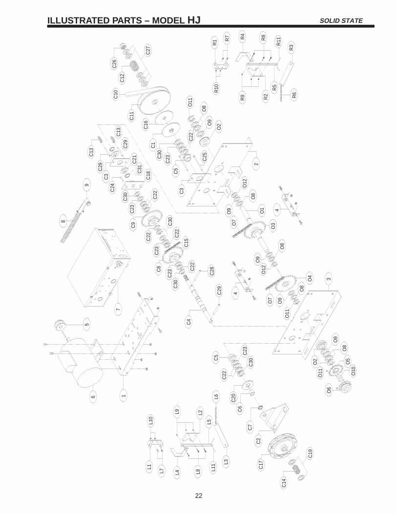
SOLID STATEILLUSTRATED PARTS – MODEL HJ
22
C26
C12
C27
C10
C11
C16
C29
C13
C1
C13
C30
C21
C29
C3
C24
C31
C22
C18
R10
R9 R2 R6
R5
R3R
11R8R4
R7
R1
O11
O8
O9
O2
2
O12
O8
C5
C22
C25
C23
C3
4O9
O1
O7
O3
O8
C30
C23
C9
C22
C30
C22
C15
C23
L10
L9 L2
L6L5
L3
L11
L8L4L7
L1
6 1
5 C4
7
C8 C22
C30
C23
4
O9
O12
C14
C17
C2
C7
C6
C20
C22
C5 C
23C
30
O6
O11
O2
O9
O8
O5
O10
C19
3O4
O8
O11
O9
O7
8
9
C29
C28

23
SOLID STATEREPLACEMENT PARTS LIST – MODEL HJ
Refer to the parts lists below for replacement kits available for your operator. If optional modifications and/oraccessories are included with your operator, certain components may be added or remove from these lists.Individual components of each kit may not be available. Please consult a parts and service representativeregarding availability of individual components. Refer to page 9 for all repair part ordering information.
K72-12556 CLUTCH SHAFT ASSEMBLY KIT
ITEM PART # DESCRIPTION QTY
C1C2C3C4C5C6C7C8C9
C10C11C12C13C14C15C16C17C18C19C20C21C22C23C24C25C26C27C28C29C30C31
Clutch PlateChain GuideInternal Disconnect PlateClutch Shaft1” Flanged Keyed BushingBushing .753 I.D. x 1.003 O.D. x 5/8NY Liner Bearing48B32/48B14 Idler Sprocket AssySprocket #48B32/48B14V Belt, 5L x 30.4”7” PulleySpring, Comp. - ClutchSpring, Comp. - DisconnectSpring, Comp. - Hoist#48 Chain 47P W/MLClutch PadChain Wheel AssyRotor AssemblySpacer .80 I.D. x 1.125 O.D. x .050Washer .753 I.D. x 2.50 O.D. x 1/8FlatwasherSpacer 1-1/32 x 1-1/2 x 1/64Spacer 1-1/16 x 1-1/2 x 1/16Key 1/4 x 1/4 x 1-1/2#10-32 x 3 SLTD RNH HD-ZPHex Castle Nut 3/4 x 16 ZPWasher 3/4 I.D. x 1-1/2 O.D. x .125Roll Pin 1/4” x 2”Roll Pin 5/16 x 2-1/2”E Ring 1” PlatedExternal Snap Ring, ZP
112121111111211111212
10512151362
K72-12557 OUTPUT SHAFT ASSEMBLY KIT
ITEM PART # DESCRIPTION QTY
O1
O2
O3
O4
O5
O6
O7
O8
O9
O10
O11
O12
Output Shaft
1” Ball Bearing
Sprocket Assy, 48B32/48B14
Sprocket, 48B332
Sprocket, 48B18 x 1” bore
Sprocket, 50B12 x 1” bore
#48 Chain 47P W/ML
Spacer 1-1/32 x 1-1/2 x 1/64
Spacer 1-1/16 x 1-1/2 x 1-16
Key 1/4 x 1/4 x 1-1/2
E Ring, 1” Plated
Push on Fastener
1
2
1
1
1
1
2
7
5
2
3
2
11-10879
12-10891
15-10885
15-48B32L
15-48B18LGE
15-50B12LGF
19-48047M
80-206-10
80-206-11
80-207-19
87-E-100
87-P-10010-1016610-1088210-1093211-1183612-1071512-1088212-1088315-1088515-1092316-5L30417-1016518-1016818-1093118-1137919-48047M39-1016775-1088475-1092180-1002280-1088380-202-2480-206-1080-206-1180-207-1980-PX10-2884-SH-7685-FW-7586-RP08-20086-RP10-20887-E-10087-E-150
INDIVIDUAL PARTS
ITEM PART # DESCRIPTION QTY
123456789
Motor PlateSide Plate RHSide Plate LHFrame Connecting Bracket2” Motor PulleyMotor Replacement KitElec. Box Replacement KitConduit, 3/8”Connector, 90 degree
111211111
10-1087110-1087210-1087310-1087417-6014See Page 17See Page 1728-1021828-10219
K75-12558 RIGHT HAND DISCONNECT ASSY KIT
ITEM PART # DESCRIPTION QTY
R1R2R3R4R5R6R7R8R9R10R11
Disconnect Support BracketYokeDisconnect LeverInterlock Switch ActuatorDisconnect Shaft12 ft. Of Sash Chain1/4-20 x 3/4 HEX HD CAP ScrScrew 10-32 x 7/8”Serrated Flange Nut, #10-32Nut, 1/4-20 Serrated FlangeRoll Pin 1/8 x 1”
11111123322
10-1070710-1070810-1087510-1089811-1087819-8A-1282-HN25-1282-SH10-1484-FN-1084-FN-2586-RP04-100
K75-12560 LEFT HAND DISCONNECT ASSY KIT
ITEM PART # DESCRIPTION QTY
L1L2L3L4L5L6L7L8L9L10L11
Disconnect Support BracketYokeDisconnect LeverInterlock Switch ActuatorDisconnect Shaft12 ft. Of Sash Chain1/4-20 x 3/4 HEX HD CAP ScrScrew 10-32 x 7/8”Serrated Flange Nut, #10-32Nut, 1/4-20 Serrated FlangeRoll Pin 1/8 x 1”
11111123322
10-1070710-1070810-1087510-10898-L11-1087819-8A-1282-HN25-1282-SH10-1484-FN-1084-FN-2586-RP04-100

c 1998, The Chamberlain Group, Inc.
All rights Reserved
OPEN / CLOSE
3 BUTTON STATION OR 3 POSITION KEYSWITCH WITH SPRING RETURN TO CENTER AND STOP BUTTON
2 OR MORE KEY LOCKOUT
4 1 10
7 6 4 5
Stop
Close
Open
Stop
Close
Open
7 6 4 5
Stop
Close
Open
2 BUTTON STATION OR 3 POSITION KEYSWITCH WITH SPRING RETURN TO CENTER
STANDARD
7 6 4
Close
Open
D1 & E2MODE ONLY
2 OR MORE7 6 4
Close
Open
Close
Open
D1 & E2MODE ONLY
OPEN / CLOSE
1 4B2, T & TS
MODE ONLY
RADIO CONTROL(24VDC ONLY)
1 BUTTON STATION OR ANY AUXILIARY DEVICE RESIDENTIAL RADIO CONTROLS
SENSING DEVICE TO REVERSE OR STOP EXTERNAL INTERLOCK
4 82 3 2 3
Remove JumperWhen Interlock is Used
ONE 2 OR MORE
STANDARD
7 6 4 5
Stop
Close
Open
IMPORTANT NOTES: The 3-Button Control Station provided must be connected for operation. If a STOP button is not used, a jumper must be placed between termianls 4 and 5.
All Wiring Types
Keyswitch
Sensing Device
LISTED DOOR OPERATOR
41B6
CONTROL CONNECTION DIAGRAM
01-10850D