Logic and Computer Design Fundamentalsinfo.psu.edu.sa/psu/cis/kalmustafa/CS_151/Lecture... ·...
26
Chapter 3 – Combinational Logic and Computer Design Fundamentals Charles Kime & Thomas Kaminski ゥ 2008 Pearson Education, Inc. (Hyperlinks are active in View Show mode) Logic Design Part 2 – Combinational Logic
Transcript of Logic and Computer Design Fundamentalsinfo.psu.edu.sa/psu/cis/kalmustafa/CS_151/Lecture... ·...

Chapter 3 – CombinationalLogic Design
Part 2 – Combinational Logic
Logic and Computer Design Fundamentals
Charles Kime & Thomas Kaminski
© 2008 Pearson Education, Inc.(Hyperlinks are active in View Show mode)
Chapter 3 – CombinationalLogic Design
Part 2 – Combinational Logic

OverviewPart 2 – Combinational Logic
• Functions and functional blocks• Rudimentary logic functions• Decoding using Decoders
Implementing Combinational Functionswith Decoders
• Encoding using Encoders• Selecting using Multiplexers
Implementing Combinational Functionswith Multiplexers
Chapter 3 2
Part 2 – Combinational Logic• Functions and functional blocks• Rudimentary logic functions• Decoding using Decoders
Implementing Combinational Functionswith Decoders
• Encoding using Encoders• Selecting using Multiplexers
Implementing Combinational Functionswith Multiplexers
Enabling Function
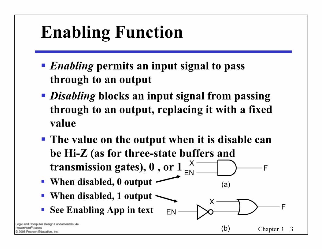
Enabling permits an input signal to passthrough to an output
Disabling blocks an input signal from passingthrough to an output, replacing it with a fixedvalue
The value on the output when it is disable canbe Hi-Z (as for three-state buffers andtransmission gates), 0 , or 1
When disabled, 0 output When disabled, 1 output See Enabling App in text
Chapter 3 3
Enabling permits an input signal to passthrough to an output
Disabling blocks an input signal from passingthrough to an output, replacing it with a fixedvalue
The value on the output when it is disable canbe Hi-Z (as for three-state buffers andtransmission gates), 0 , or 1
When disabled, 0 output When disabled, 1 output See Enabling App in text
XFEN
(a)
ENX
F
(b)

Decoding - the conversion of an n-bit inputcode to an m-bit output code withn m 2n such that each valid code wordproduces a unique output code
Circuits that perform decoding are calleddecoders
Here, functional blocks for decoding are• called n-to-m line decoders, where m 2n, and• generate 2n (or fewer) minterms for the n input
variables
Decoding
Chapter 3 4
Decoding - the conversion of an n-bit inputcode to an m-bit output code withn m 2n such that each valid code wordproduces a unique output code
Circuits that perform decoding are calleddecoders
Here, functional blocks for decoding are• called n-to-m line decoders, where m 2n, and• generate 2n (or fewer) minterms for the n input
variables
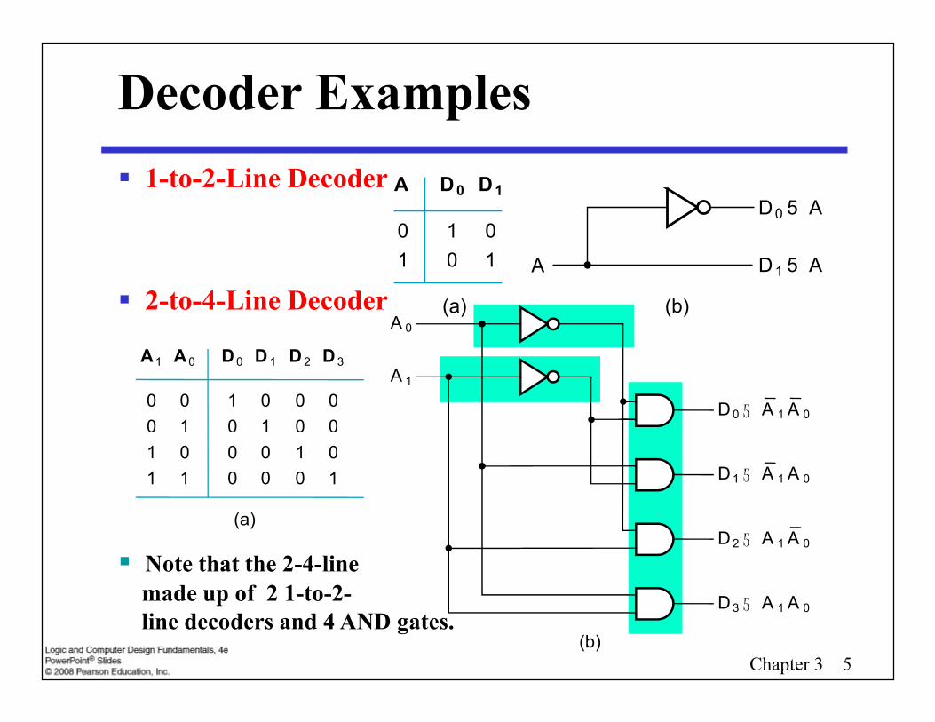
1-to-2-Line Decoder
2-to-4-Line Decoder
Decoder ExamplesA D0 D1
0 1 01 0 1
(a) (b)
D1 5 AA
D0 5 A
A 1 A 0 D 0 D 1 D 2 D 3A
A 0
Chapter 3 5
1-to-2-Line Decoder
2-to-4-Line Decoder
Note that the 2-4-linemade up of 2 1-to-2-line decoders and 4 AND gates.
A 1
0011
A 0
0101
D 0
1000
D 1
0100
D 2
0010
D 3
0001
(a)
D 0 5 A 1A 0
D 1 5 A 1A 0
D 2 5 A 1A 0
D 3 5 A 1A 0
(b)
A 1
Decoder Expansion - Example 1
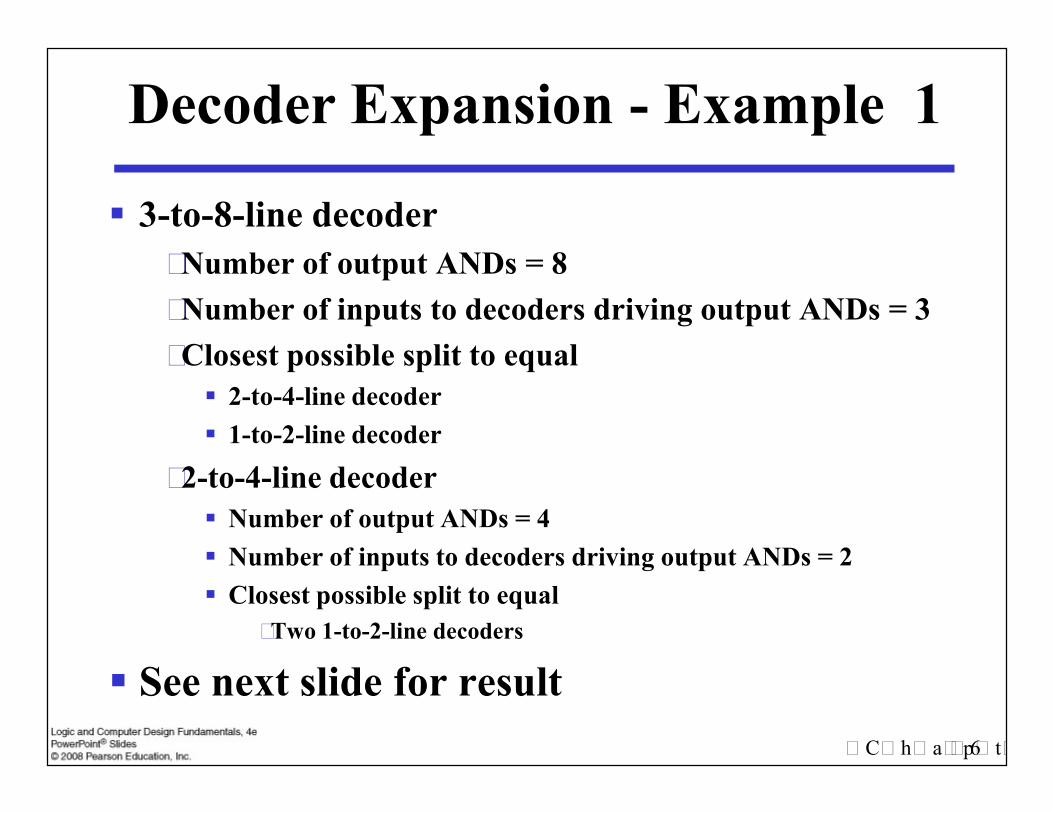
3-to-8-line decoder• Number of output ANDs = 8• Number of inputs to decoders driving output ANDs = 3• Closest possible split to equal
2-to-4-line decoder 1-to-2-line decoder
• 2-to-4-line decoder Number of output ANDs = 4 Number of inputs to decoders driving output ANDs = 2 Closest possible split to equal
• Two 1-to-2-line decoders
See next slide for resultChapter 3 6
3-to-8-line decoder• Number of output ANDs = 8• Number of inputs to decoders driving output ANDs = 3• Closest possible split to equal
2-to-4-line decoder 1-to-2-line decoder
• 2-to-4-line decoder Number of output ANDs = 4 Number of inputs to decoders driving output ANDs = 2 Closest possible split to equal
• Two 1-to-2-line decoders
See next slide for result
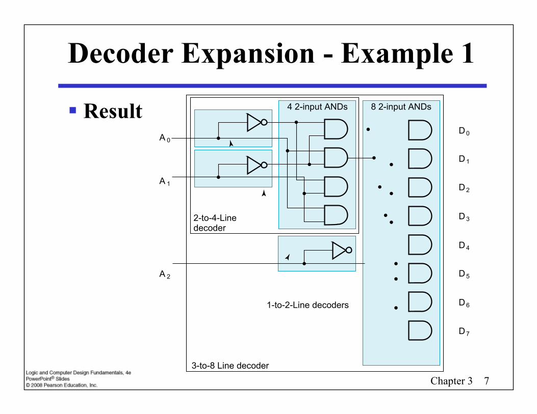
Decoder Expansion - Example 1
Result
3-to-8 Line decoder
1-to-2-Line decoders
4 2-input ANDs 8 2-input ANDs
2-to-4-Linedecoder
D0A 0
A 1
A 2
D1
D2
D3
D4
D5
D6
D7
Chapter 3 73-to-8 Line decoder
1-to-2-Line decoders
4 2-input ANDs 8 2-input ANDs
2-to-4-Linedecoder
D0A 0
A 1
A 2
D1
D2
D3
D4
D5
D6
D7

In general, attach m-enabling circuits to the outputs See truth table below for function
• Note use of X’s to denote both 0 and 1• Combination containing two X’s represent four binary combinations
Alternatively, can be viewed as distributing value of signalEN to 1 of 4 outputs
In this case, called ademultiplexer
EN
A 1
A 0D0
D1
D2
D3
(b)
EN A1 A0 D0 D1 D2 D3
01111
X0011
X0101
01000
00100
00010
00001
(a)
Decoder with Enable
Chapter 3 8
In general, attach m-enabling circuits to the outputs See truth table below for function
• Note use of X’s to denote both 0 and 1• Combination containing two X’s represent four binary combinations
Alternatively, can be viewed as distributing value of signalEN to 1 of 4 outputs
In this case, called ademultiplexer
EN
A 1
A 0D0
D1
D2
D3
(b)
EN A1 A0 D0 D1 D2 D3
01111
X0011
X0101
01000
00100
00010
00001
(a)
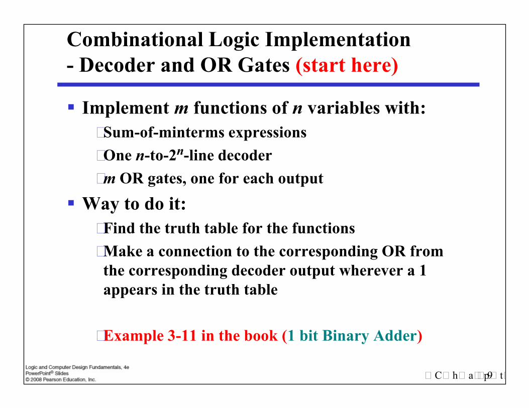
Combinational Logic Implementation- Decoder and OR Gates (start here)
Implement m functions of n variables with:• Sum-of-minterms expressions• One n-to-2n-line decoder• m OR gates, one for each output
Way to do it:• Find the truth table for the functions• Make a connection to the corresponding OR from
the corresponding decoder output wherever a 1appears in the truth table
• Example 3-11 in the book (1 bit Binary Adder)
Chapter 3 9
Implement m functions of n variables with:• Sum-of-minterms expressions• One n-to-2n-line decoder• m OR gates, one for each output
Way to do it:• Find the truth table for the functions• Make a connection to the corresponding OR from
the corresponding decoder output wherever a 1appears in the truth table
• Example 3-11 in the book (1 bit Binary Adder)

Encoding Encoding - the opposite of decoding - the conversion
of an m-bit input code to a n-bit output code with n m 2n such that each valid code word produces aunique output code
Circuits that perform encoding are called encoders An encoder has 2n (or fewer) input lines and n output
lines which generate the binary code correspondingto the input values
Typically, an encoder converts a code containingexactly one bit that is 1 to a binary code corres-ponding to the position in which the 1 appears.
Chapter 3 10
Encoding - the opposite of decoding - the conversionof an m-bit input code to a n-bit output code with n m 2n such that each valid code word produces aunique output code
Circuits that perform encoding are called encoders An encoder has 2n (or fewer) input lines and n output
lines which generate the binary code correspondingto the input values
Typically, an encoder converts a code containingexactly one bit that is 1 to a binary code corres-ponding to the position in which the 1 appears.
Encoder Example
A decimal-to-BCD encoder• Inputs: 10 bits corresponding to decimal
digits 0 through 9, (D0, …, D9)• Outputs: 4 bits with BCD codes• Function: If input bit Di is a 1, then the
output (A3, A2, A1, A0) is the BCD code for i, The truth table could be formed, but
alternatively, the equations for each of thefour outputs can be obtained directly.
Chapter 3 11
A decimal-to-BCD encoder• Inputs: 10 bits corresponding to decimal
digits 0 through 9, (D0, …, D9)• Outputs: 4 bits with BCD codes• Function: If input bit Di is a 1, then the
output (A3, A2, A1, A0) is the BCD code for i, The truth table could be formed, but
alternatively, the equations for each of thefour outputs can be obtained directly.

Encoder Example (continued)
Input Di is a term in equation Aj if bit Aj is 1in the binary value for i.
Equations:A3 = D8 + D9
A2 = D4 + D5 + D6 + D7
A1 = D2 + D3 + D6 + D7
A0 = D1 + D3 + D5 + D7 + D9
F1 = D6 + D7 can be extracted from A2 and A1Is there any cost saving?
Chapter 3 12
Input Di is a term in equation Aj if bit Aj is 1in the binary value for i.
Equations:A3 = D8 + D9
A2 = D4 + D5 + D6 + D7
A1 = D2 + D3 + D6 + D7
A0 = D1 + D3 + D5 + D7 + D9
F1 = D6 + D7 can be extracted from A2 and A1Is there any cost saving?

Priority Encoder
If more than one input value is 1, then theencoder just designed does not work.
One encoder that can accept all possiblecombinations of input values and producea meaningful result is a priority encoder.
Among the 1s that appear, it selects themost significant input position (or theleast significant input position) containinga 1 and responds with the correspondingbinary code for that position.
Chapter 3 13
If more than one input value is 1, then theencoder just designed does not work.
One encoder that can accept all possiblecombinations of input values and producea meaningful result is a priority encoder.
Among the 1s that appear, it selects themost significant input position (or theleast significant input position) containinga 1 and responds with the correspondingbinary code for that position.

Priority Encoder Example Priority encoder with 4 inputs (D3, D2, D1, D0) - highest priority to most
significant 1 present - Code outputs A1 and A0.
Inputs Outputs
D3 D2 D1 D0 A1 A00 0 0 0 X X0 0 0 1 0 0
Chapter 3 14
Priority encoder with 4 inputs (D3, D2, D1, D0) - highest priority to mostsignificant 1 present - Code outputs A1 and A0.
0 0 0 1 0 00 0 1 X 0 10 1 X X 1 01 X X X 1 1
The input having most ones would takethe value 3 (11) in its output
Selecting of data or information is a criticalfunction in digital systems and computers
Circuits that perform selecting have:• A set of information inputs from which the selection
is made• A single output• A set of control lines for making the selection
Logic circuits that perform selecting are calledmultiplexers
Selecting
Chapter 3 15
Selecting of data or information is a criticalfunction in digital systems and computers
Circuits that perform selecting have:• A set of information inputs from which the selection
is made• A single output• A set of control lines for making the selection
Logic circuits that perform selecting are calledmultiplexers

Multiplexers
A multiplexer selects information from aninput line and directs the information toan output line
A typical multiplexer has n control inputs(Sn 1, … S0) called selection inputs, 2n
information inputs (I2n
1, … I0), and oneoutput Y
Chapter 3 16
A multiplexer selects information from aninput line and directs the information toan output line
A typical multiplexer has n control inputs(Sn 1, … S0) called selection inputs, 2n
information inputs (I2n
1, … I0), and oneoutput Y
2-to-1-Line Multiplexer
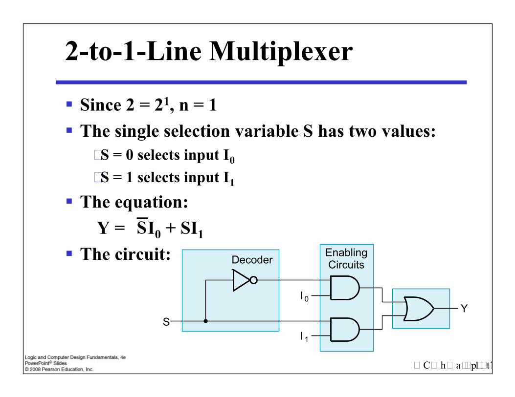
Since 2 = 21, n = 1 The single selection variable S has two values:
• S = 0 selects input I0
• S = 1 selects input I1
The equation:Y = I0 + SI1
The circuit:
Chapter 3 17
Since 2 = 21, n = 1 The single selection variable S has two values:
• S = 0 selects input I0
• S = 1 selects input I1
The equation:Y = I0 + SI1
The circuit:S
S
I0
I1
DecoderEnablingCircuits
Y

2-to-1-Line Multiplexer
D04D05
D03D02D01D00
OutD14D15
D13D12D11D10
Out
11
1
11
11
00
0
0
0
00
Y Z
00110101
01101001
Y S
S I0 I1 Y
0 0 0 0
0 0 1 0
0 1 0 1
0 1 1 1
Chapter 3 18
D05D06D07
S1S0
AB
S2
C
D15D16D17
S1S0
AB
S2
C
111 0
00
8-to-1MUX
8-to-1MUX
00110101
01101001
SI0
I1
XYZ
Another example is detectingA three bits prime number
0 1 1 1
1 0 0 0
1 0 1 1
1 1 0 0
1 1 1 1

Example: 4-to-1-line Multiplexer
2-to-22-line decoder 22 2 AND-OR
S1Decoder
S0
Y
S1Decoder
S0
Y
S1Decoder
4 3 2 AND-ORS0
Y
I2
I3
I1
I0
Chapter 3 19
S1Decoder
S0
Y
S1Decoder
S0
Y
S1Decoder
4 3 2 AND-ORS0
Y
I2
I3
I1
I0

Example: Gray to Binary Code
Design a circuit toconvert a 3-bit Graycode to a binary code
The formulation givesthe truth table on theright
It is obvious from thistable that X = C and theY and Z are more complex
GrayA B C
Binaryx y z
0 0 0 0 0 01 0 0 0 0 11 1 0 0 1 00 1 0 0 1 1
Chapter 3 20
Design a circuit toconvert a 3-bit Graycode to a binary code
The formulation givesthe truth table on theright
It is obvious from thistable that X = C and theY and Z are more complex
0 1 0 0 1 10 1 1 1 0 01 1 1 1 0 11 0 1 1 1 00 0 1 1 1 1

Gray to Binary (continued)
Rearrange the table sothat the input combinationsare in counting order
Functions y and z canbe implemented usinga dual 8-to-1-linemultiplexer by:
• connecting A, B, and C to the multiplexer select inputs• placing y and z on the two multiplexer outputs• connecting their respective truth table values to the inputs
GrayA B C
Binaryx y z
0 0 0 0 0 00 0 1 1 1 10 1 0 0 1 10 1 1 1 0 01 0 0 0 0 11 0 1 1 1 01 1 0 0 1 01 1 1 1 0 1
Chapter 3 21
Rearrange the table sothat the input combinationsare in counting order
Functions y and z canbe implemented usinga dual 8-to-1-linemultiplexer by:
• connecting A, B, and C to the multiplexer select inputs• placing y and z on the two multiplexer outputs• connecting their respective truth table values to the inputs
GrayA B C
Binaryx y z
0 0 0 0 0 00 0 1 1 1 10 1 0 0 1 10 1 1 1 0 01 0 0 0 0 11 0 1 1 1 01 1 0 0 1 01 1 1 1 0 1

Gray to Binary (continued)
D04D05
D03D02D01D00
OutD14D15
D13D12D11D10
Out
11
1
11
11
00
0
0
0
00
Y Z
Chapter 3 22
D05D06D07
S1S0
AB
S2
C
D15D16D17
S1S0
AB
S2
C
111 0
00
8-to-1MUX
8-to-1MUX

Another example: 3-11 in the book(1 bit Binary Adder) that we did last class
We solved the problem last class using 3-8 line Decoder,now we do it using multiplexers.
The truth table for the adder is as follows:X Y Z S C
0 0 0 0 0
We solved the problem last class using 3-8 line Decoder,now we do it using multiplexers.
The truth table for the adder is as follows:
Chapter 3 23
0 0 1 1 0
0 1 0 1 0
0 1 1 0 1
1 0 0 1 0
1 0 1 0 1
1 1 0 0 1
1 1 1 1 1
1 bit Binary Adder
since there are three selections (X,Y,Z)and a total of 8 inputs, (as numbers of bitsfor the C and the S columns), we can use8-1 line multiplexer for C and for the Soutputs:
since there are three selections (X,Y,Z)and a total of 8 inputs, (as numbers of bitsfor the C and the S columns), we can use8-1 line multiplexer for C and for the Soutputs:
Chapter 3 24
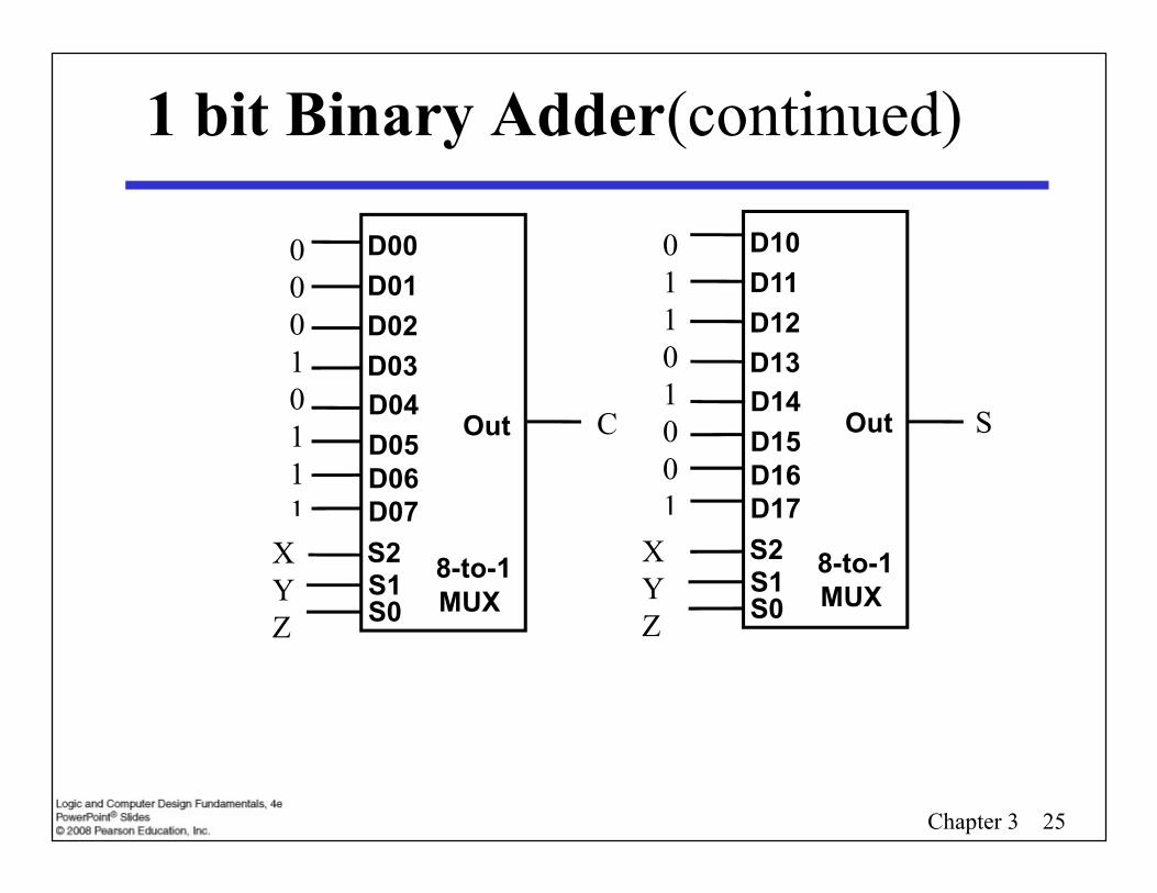
1 bit Binary Adder(continued)
D04D05
D03D02D01D00
OutD14D15
D13D12D11D10
Out
11
1
11
11
00
0
0
0
00
Y Z
00010111
01101001
C S
Chapter 3 25
D05D06D07
S1S0
AB
S2
C
D15D16D17
S1S0
AB
S2
C
111 0
00
8-to-1MUX
8-to-1MUX
00010111
01101001
XYZ
XYZ
Terms of Use All (or portions) of this material © 2008 by Pearson
Education, Inc. Permission is given to incorporate this material or
adaptations thereof into classroom presentations andhandouts to instructors in courses adopting the latestedition of Logic and Computer Design Fundamentals asthe course textbook.
These materials or adaptations thereof are not to besold or otherwise offered for consideration.
This Terms of Use slide or page is to be included withinthe original materials or any adaptations thereof.
Chapter 3 26
All (or portions) of this material © 2008 by PearsonEducation, Inc.
Permission is given to incorporate this material oradaptations thereof into classroom presentations andhandouts to instructors in courses adopting the latestedition of Logic and Computer Design Fundamentals asthe course textbook.
These materials or adaptations thereof are not to besold or otherwise offered for consideration.
This Terms of Use slide or page is to be included withinthe original materials or any adaptations thereof.