Drilling, logging, and sampling of five ... - hmis.hanford.gov
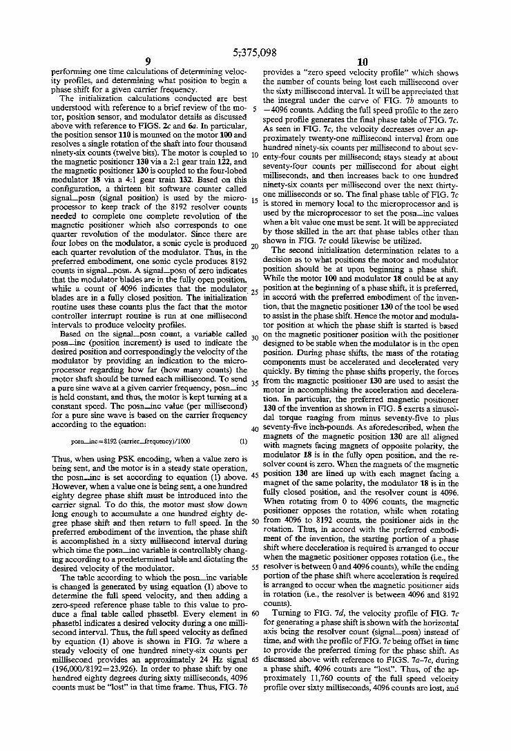
United States Patent [191 Malone et a1.
USOO5375098A
[11] Patent Number: 5,375,098 [451 Date of Patent: * Dec. 20, 1994
[54] LoGGING WHILE DRILLING TOOLS, SYSTEMS, AND METHODS CAPABLE OF TRANSMITTING DATA AT A PLURALITY OF DIFFERENT FREQUENCIES
[75] Inventors: David Malone, Sugar Land; Mike Johnson, Houston, both of Tex.
[73] Assignee: Schlumberger Technology Corporation, Houston, Tex.
[ * ] Notice: The portion of the term of this patent subsequent to Aug. 17, 2010 has been disclaimed.
[21] Appl. No.: 934,137 [22] Filed: Aug. 21, 1992
[51] Int. Cl.5 ............................................. .. H04H 9/00 [52] US. Cl. ...................................... .. 367/83; 367/84;
175/40; 340/853.1 [58] Field of Search ..................... .. 367/84, 83, 85, 81;
175/40, 45; 340/853.3, 854.3, 856.4, 853.1 [56] References Cited
U.S. PATENT DOCUMENTS
Re. 29,734 8/1978 Manning ........................... .. 175/232 Re. 30,055 7/ 1979 Claycomb 340/ 182 D 3,309,656 3/1967 Godbey ..... .. 340/ 18 3,705,603 12/1972 Hawk . . . . . . . . . . . .. 175/50
3,764,968 10/ 1973 Anderson ..... .. 340/ 18 NC 3,764,969 10/1973 Cubberly, Jr. . ....... .. 175/232
3,789,355 1/ 1974 Patton ........... .. 340/18 LD 3,792,428 2/ 1974 Harrell et al. .. ......... .. 322/32
3,792,429 2/ 1974 Patton et a1. 340/ 18 LD 3,820,063 6/1974 Sexton et a1. ......... .. 175/50
3,821,696 6/ 1974 Harrell et al. .. 340/ 18 LD 3,932,836 1/1976 Harrell et a1. .. ....... .. 318/171
3,982,224 9/1976 Patton ........... .. 340/ 18 NC 4,100,528 7/1978 Bernard et a1 ....... .. 318/314 4,103,281 7/1978 Strom et a1. 340/18 LD 4,167,000 9/ 1979 Bernard et a1 ..... .. 367/ 84 4,785,300 11/1988 Chin et a1. .... .. 367/84
4,847,815 7/ 1989 Malone ......... .. . 367/84
5,146,433 9/ 1992 Kosmala et a1. .................... .. 367/83
5,182,731 1/ 1993 Hoelscher et a1. .................. .. 367/84 ' 5,237,540 8/1993 Malone ............. .. 367/81
5,249,161 9/1993 Jones et al. .................... 367/83
OTHER PUBLICATIONS
T. Kenjo et al., Permanent-Magnet and Brushless DC Motors, pp. 79-102, 1985, Oxford, England. Clifton Precision, Litton Systems, Inc., Synchro and Resolver Engineering Handbook, 1989, Clifton Heights, Pa.
Primary Examiner-J. Woodrow Eldred Attorney, Agent, or Firm-John J. Ryberg; David P. Gordon; Wayne I. Kanak
[57] ABSTRACT A LWD tool is disclosed comprising, a stator, a rotor which rotates relative to the stator thereby effecting a signal in the borehole ?uid ?owing therethrough, a brushless DC motor coupled to the rotor for driving the rotor, a position sensor coupled to the motor for sensing the rotational position of the motor, motor drive elec tronics coupled to motor for driving the motor, and a microprocessor coupled to the position sensor and to the drive electronics for controlling the drive signals to the motor based on the actual and desired positions of the motor. By controlling the drive signal to the motor, the speed of the motor is controlled, thus effecting changes in frequency and/or phase of the signal in the borehole ?uid or mud. With the ability to change the frequency and/ or phase, different encoding techniques such as PSK-type and FSK-type can be used. Other preferred aspects of the invention include: choosing carrier frequency based on system noise; the use of magnetic positioner and the coordination of the decela ration and acceleration of the modulator to correspond to desired magnetic positioner positions in effecting a phase shift; and jamming avoidance techniques utilizing the position sensor and microprocessor.
22 Claims, 16 Drawing Sheets
2 RESOLVER GEARTRA
MAGNETIC 411 POSITIONER GEARTRAIN MODULATOR

US. Patent Dec. 20, 1994 Sheet 1 of 16 5,375,098
30
L /J \ ' a2 36';
PROCESSOR
a4
PUMPS ‘2
23(27 24 13 -1- 17 1o
/ E? 22 fl 31 ’
I \ ._
’ h- ‘2% MUD PIT
26A I, 26 \ / ' u
< '29 /


US. Patent Dec. 20, 1992; Sheet 3 0f 16 5,375,098
FIG. 2b
US. Patent Dec. 20, 1994 Sheet 4 of 16 5,375,098
FIG. 20

Dec. 20, 1994 Sheet 5 of 16 5,375,098 US. Patent
361 \\\\\\\\\\\\\\\~

US. Patent Dec. 20, 1991 Sheet 6 of 16 5,375,098

US. Patent Dec. 20, 1994 Sheet 7 of 16 5,375,098
O <I'
92 U.
.8; r——-r-rrrm Q’ 9
8|. “
8 1-K -_N
[is . i is
5;?! g §| @ F- q q:
2_ - - _g
N LL. ‘2
a N 7 169/1

US. Patent Dec. 20, 1994 Sheet 8 of 16 5,375,098
Zach-huge 538mm @052
36E
mam
E2159‘??? _ M25:


US. Patent Dec. 20, 1994 Sheet 10 0f 16 5,375,098
VELOCITY (COUNTS/ms ) L
196
TIME (ms)
1 | u n I I *’ O 10 2O 30 40 50 60 PHASETBIUNDEX)
F|G.70
VELOCITY ‘(COUNTS/ms ) I
196
T|ME(ms ) 7 0R
PHASETBHINDEX)
VELOClTY(COUNTS/ms )
196
TlME(ms ) | I 1 I l | l >
0 10 20 30 40 50 60 PHASETBI (INDEX)
US. Patent Dec. 20, 1994 Sheet 12 of 16 5,375,098
an .wE
$82M:
:2 m N _ G
m5: 1 1 1 1.
_ _ _
_ n u n 35.5% “ 555% m 35.5%
_
_ n u
_ _
_ _
tam mast L:
3% $38”:
US. Patent Dec. 20, 1994 Sheet 14 of 16
OBTAIN SPECTRUM OF NOISE WITHOUT MWD IN HOLE OR
DURING PERIODS WHERE MWD IS NOT OPERATING
N302
DEIERMINE FREQUENCY BANDS WITHIN TOOL OPERATING RANGE
WHERE NOISE IS MINIMAL
RECONFIGURE TOOL FOR CARRIER FREQUENCY WITHIN BANDS OF MINIMAL NOISE USING DOWNLINK OR SURFACE CONFIGURATION
FIG.8
5,375,098

5,375,098 1
LOGGING WHILE DRILLING TOOLS, SYSTEMS, AND METHODS CAPABLE OF TRANSMITTING
DATA AT A PLURALITY OF DIFFERENT ' _ FREQUENCIES
BACKGROUND OF THE INVENTION 1. Field of the Invention This invention relates to communication systems, and
particularly, to systems and methods for generating and transmitting data signals to the surface of the earth in a logging-while-drilling system.
2. Prior Art Logging-while-drilling or measurement-while-drill
ing (both hereinafter referred to as LWD) involves the transmission to the earth’s surface of downhole mea surements taken during drilling. The measurements are generally taken by instruments mounted within drill collars above the drill bit. Indications of the measure ments must then be transmitted uphole to the earth’s surface. Various schemes have been proposed for achieving transmission of measurement information to the earth’s surface. For example, one proposed tech nique transmits logging measurements by means of insu lated electrical conductors extending through the drill string. This scheme, however, requires adaptation of drill string pipes including expensive provision for elec trical connections at the drill pipe couplings. Another proposed scheme employs an acoustic wave that is generated downhole and travels upward through the metal drill string; but the high levels of interfering noise in a drill string are a problem in this technique. The most common scheme for transmitting measure
ment information utilizes the drilling ?uid within the borehole as a transmission medium for acoustic waves modulated to represent the measurement information. Typically, drilling ?uid or “mud” is circulated down ward through the drill string and drill bit and upward through the annulus de?ned by the portion of the bore hole surrounding the drill string. The drilling ?uid not only removes drill cuttings and maintains a desired hydrostatic pressure in the borehole, but cools the drill bit. In a species of the technique referred to above, a downhole acoustic transmitter known as a rotary valve or “mud siren”, repeatedly interrupts the ?ow of the drilling ?uid, and this causes a varying pressure wave to be generated in the drilling ?uid at a frequency that is proportional to the rate of interruption. Logging data is transmitted by modulating the acoustic carrier as a function of the downhole measured data. One dif?culty in transmitting measurement informa
tion via the drilling mud is that the signal received is typically of low amplitude relative to the noise gener ated by the mud pumps which circulate the mud, as the downhole signal is generated remote from the uphole sensors while the mud pumps are close to the uphole sensors. In particular, where the downhole tool gener ates a pressure wave that is phase modulated to encode binary data, such as is disclosed in US. Pat. No. 4,847,815 and assigned to the assignee hereof, and where the periodic noise sources are at frequencies which are at or near the frequency of the carrier wave (e.g. 12 Hz), difficulties arise. Mud pumps are large positive displacement pumps
which generate ?ow by moving a piston back and forth within a cylinder while simultaneously opening and closing intake and exhaust valves. A mud pump typi cally has three pistons attached to a common drive
10
25
'30
35
45
50
55
65
2 shaft. These pistons are one hundred and twenty de grees out of phase with one another to minimize pres sure variations. Mud pump noise is caused primarily by pressure variations while forcing mud through the ex haust valve. The fundamental frequency in Hertz of the noise
generated by the mud pumps is equal to the strokes per minute of the mud pump divided by sixty. Due to the physical nature and operation of mud pumps, harmonics are also generated, leading to noise peaks of varying amplitude at all integer values of the fundamental fre quency. The highest amplitudes generally occur at inte ger multiples of the number of pistons per pump times the fundamental frequency, e.g., 3 F, 6 F, 9 F, etc. for a pump with three pistons. Mud pumps are capable of generating very large
noise peaks if pump pressure variations are not damp ened. Thus, drilling rigs are typically provided with pulsation dampeners at the output of each pump. De spite the pulsation dampeners, however, the mud pump noise amplitude is typically much greater than the am plitude of the signal being received from the downhole acoustic transmitter.
SUMMARY OF THE INVENTION
It is therefore an object of the invention to provide a LWD system and method where the carrying fre quency of the generated signal is chosen to avoid noisy areas of the frequency spectrum.
It is another object of the invention to provide a tool which can generate a signal at different frequencies up to at least 24 Hz.
It is a further object of the invention to provide a LWD tool which utilizes a brushless DC motor for turning a rotor and generating a sinusoidal signal of desired frequency. Another object of the invention is to provide a LWD
tool capable of using different data transmission tech niques such as phase shift keying (PSK) and frequency shift keying (FSK) to provide an LWD signal. A further object of the invention is to provide a
LWD tool having a permanent magnet, brushless DC motor with a position sensor and a microprocessor for relatively high frequency data transmission and for jamming avoidance. An additional object of the invention is to provide a
LWD tool utilizing a brushless DC motor for providing a PSK signal in conjunction with a magnetic positioner on a drive shaft of the motor, where the phase shifting is coordinated with the magnetic positioner at desired times in the cycle of the motor. Yet another object of the invention is to provide a
jamming avoidance algorithm for a LWD tool utilizing a brushless DC motor with a position sensor and a mi croprocessor.
In accord with the objects of the invention, a LWD tool is provided and generally comprises, a stator, a rotor which rotates relative to the stator thereby effect ing a signal in the borehole ?uid ?owing therethrough, a brushless DC motor coupled to the rotor for driving the rotor, a position sensor coupled to the motor for sensing the rotational position of the motor, motor drive electronics coupled to motor for driving the motor, and a microprocessor coupled to the position sensor and to the drive electronics for controlling the drive signals to the motor based on the actual and desired positions of the motor. By controlling the drive signal to the motor,

5,375,098 3
the speed of the motor is controlled, thus effecting changes in frequency and/or phase of the signal in the borehole ?uid or mud. With the ability to change the frequency and/or phase, different encoding techniques such as phase shift keying (PSK) and variants thereon, and frequency shift keying (F SK) and variants thereon can be used. One preferred embodiment of the LWD tool uses
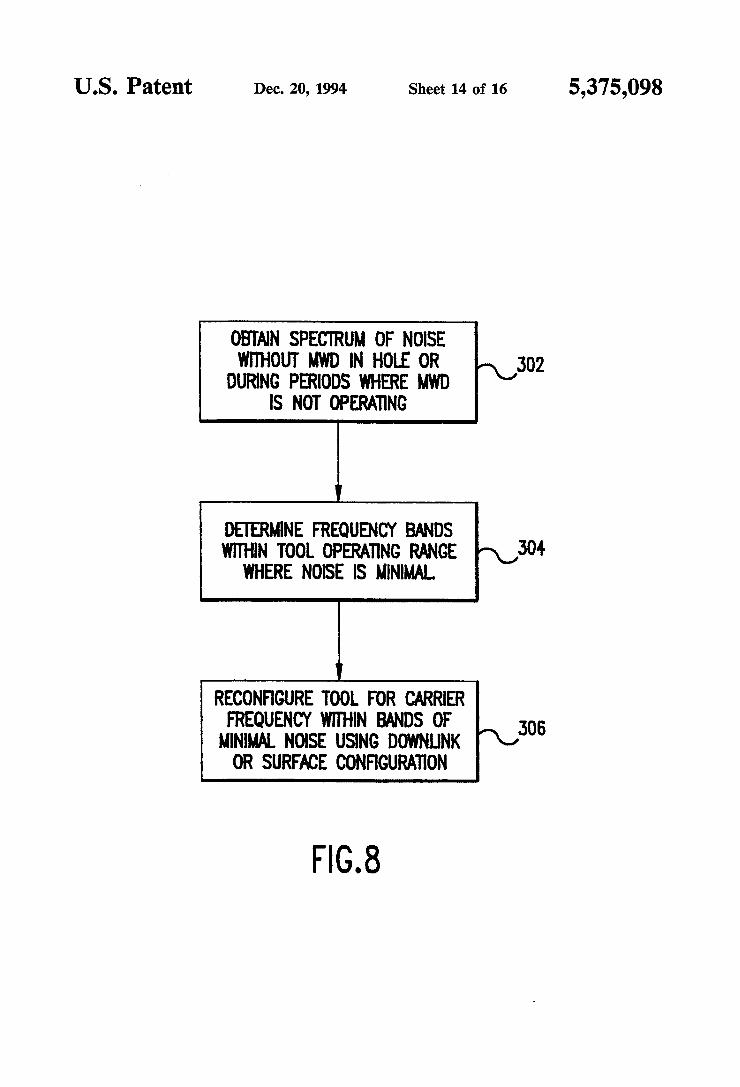
PSK-type encoding. Because the LWD tool has the ability to provide signals of different frequencies, a method which utilizes that ability in a PSK-type coding scheme is provided. The method comprises obtaining a sample of the noise in the system, analyzing the system noise with a spectrum analyzer (i.e., taking a Fourier transform of the noise), and choosing an operating car rier frequency for the LWD tool which generates the PSK-type encoded signal at a frequency with relatively little noise. In this manner the signal/noise ratio of the tool is effectively increased. Another preferred embodiment of the LWD tool uses
FSK-type encoding. The previously summarized noise analysis of the system is also advantageously utilized in the FSK-type system, as the frequencies used for con veying information are chosen to avoid high system noise frequencies. With PSK-type encoding, if, for ex ample, eight different transmission frequencies are uti lized, three bits of information can be sent at a time during each signal period.
Another preferred aspect of the tool is the provision of a magnetic positioner on a rotating component of the drive shaft system (e. g., on the drive shaft of the motor). The magnetic positioner guarantees that upon shut down of the system, the rotor is rotated to a fully open position. In the fully open position, mud ?ows through relatively unimpeded, and jamming and/or loss of power is avoided.
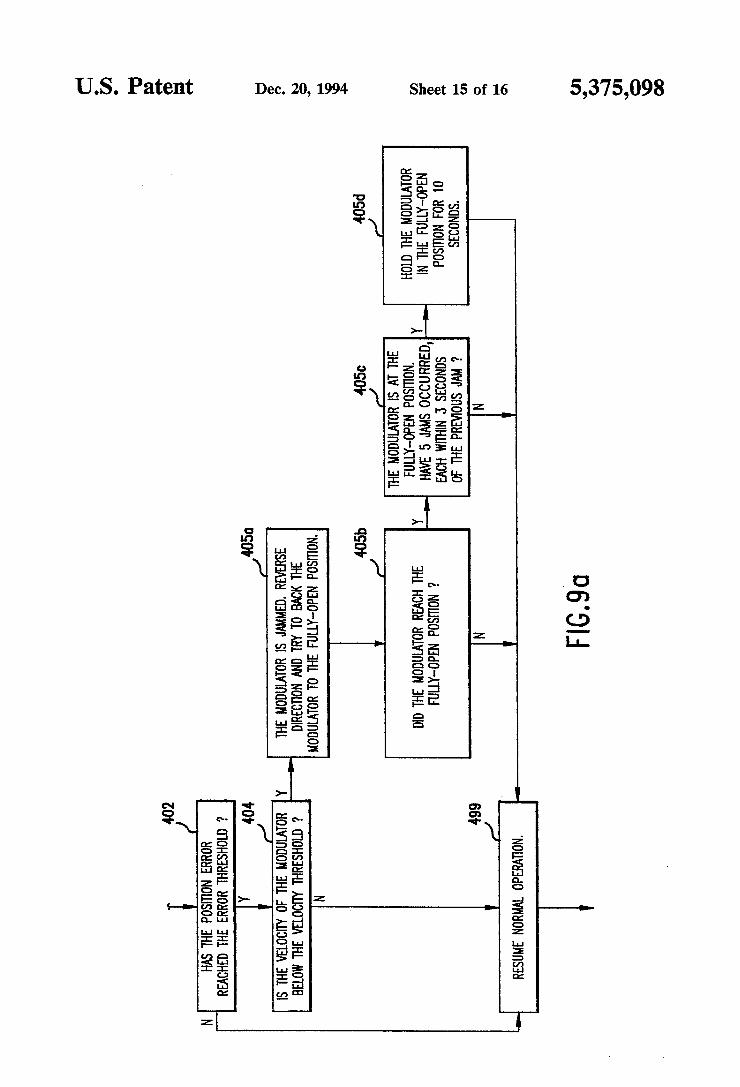
Other aspects of the invention include the timing of the phase shifting of the PSK-type signal, and an anti jamming algorithm. The timing of the phase shifting of the PSK-type signal is arranged to coordinate with the magnetic positioner so that the drive shaft is in position for the magnetic positioner to provide resistance during the period of time the rotor is slowing down, while the drive shaft is in position for the magnetic positioner to provide impetus during the period of time the rotor is speeding up. This timing of the phase shifting is accom plishable due to the fact that the motor has a position sensor. The anti-jamming algorithm is also accomplish able due to the position sensor. The anti-jamming algo rithm utilizes the position error of the motor in conjunc tion with the motor velocity in order to determine whether or not there is a jam. If the rotor velocity is below a predetermined velocity threshold, and the posi tion error has reached a predetermined maximum value, a jam is detected. However, where the position error has reached the predetermined maximum value, but the velocity threshold has not been met, rather than a jam, a low power state is declared, where not enough power is available to turn the motor at the commanded speed. In this state, the carrier frequency of the system is pref erably reduced.
Additional objects and advantages of the invention will become apparent to those skilled in the art upon reference to the detailed description taken in conjunc tion with the provided ?gures.
20
40
45
50
65
4
BRIEF DESCRIPTION OF THE DRAWINGS
FIG. 1 is a schematic diagram showing a LWD tool in its typical drilling environment. _ FIG. 2 is a schematic diagram of the LWD tool of the
invention which shows how FIGS. 2a-2d relate to each other and also shows other components of the LWD tool. FIGS. 2a and 2b, and 2c and 2d are respectively par
tially cut-away perspective representations, and cross sectional representations through portions of the pre ferred LWD tool of the invention. FIGS. 30 and 3b are respectively isometric and front
plan views of the preferred stator of FIG. 2d. FIGS. 4a, 4b, and 4c are respectively isometric, front
plan, and side elevational views of the preferred rotor of FIG. 2d. FIG. 5 is a cross sectional view of the magnetic posi
tioner of FIG. 2c. FIG. 6a is a block diagram of the motor drive appara
tus and motor controller function of the invention. FIG. 6b is a software ?ow diagram of the motor
control software for the microprocessor of FIGS. 2 and 6a FIGS. 7a-7c are graphs which show rotor velocity
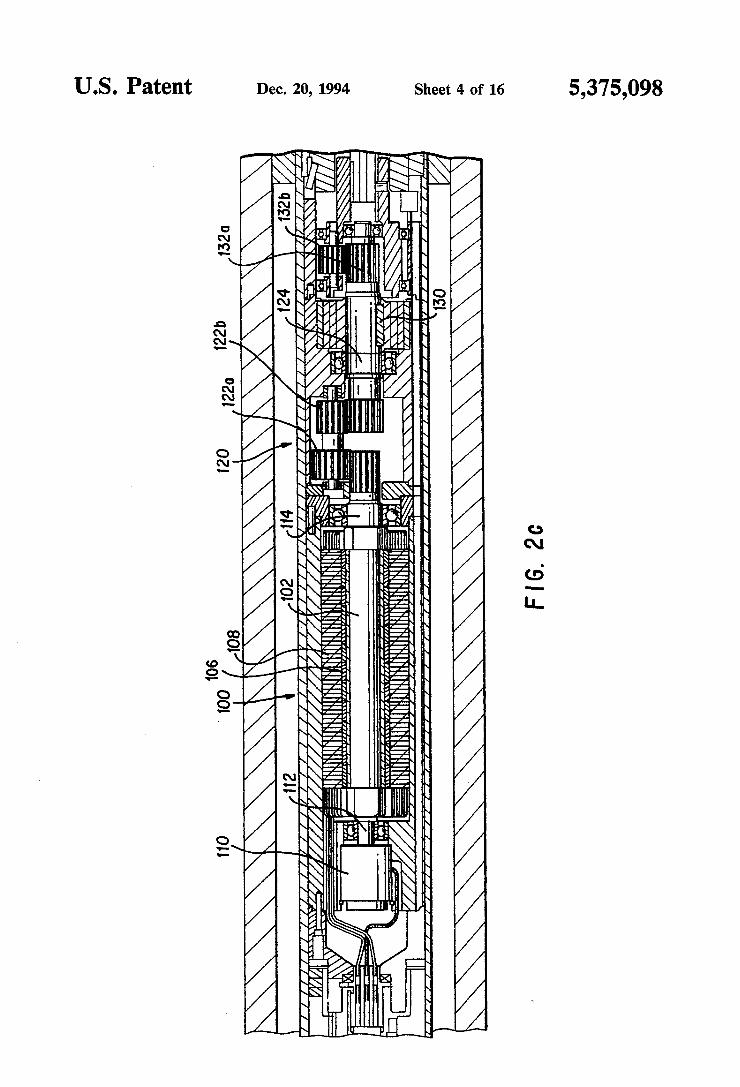
over time for a full speed velocity pro?le, a zero speed referenced velocity pro?le, and a phase shift velocity pro?le respectively. FIG. 7d is a graph which shows rotor velocity versus
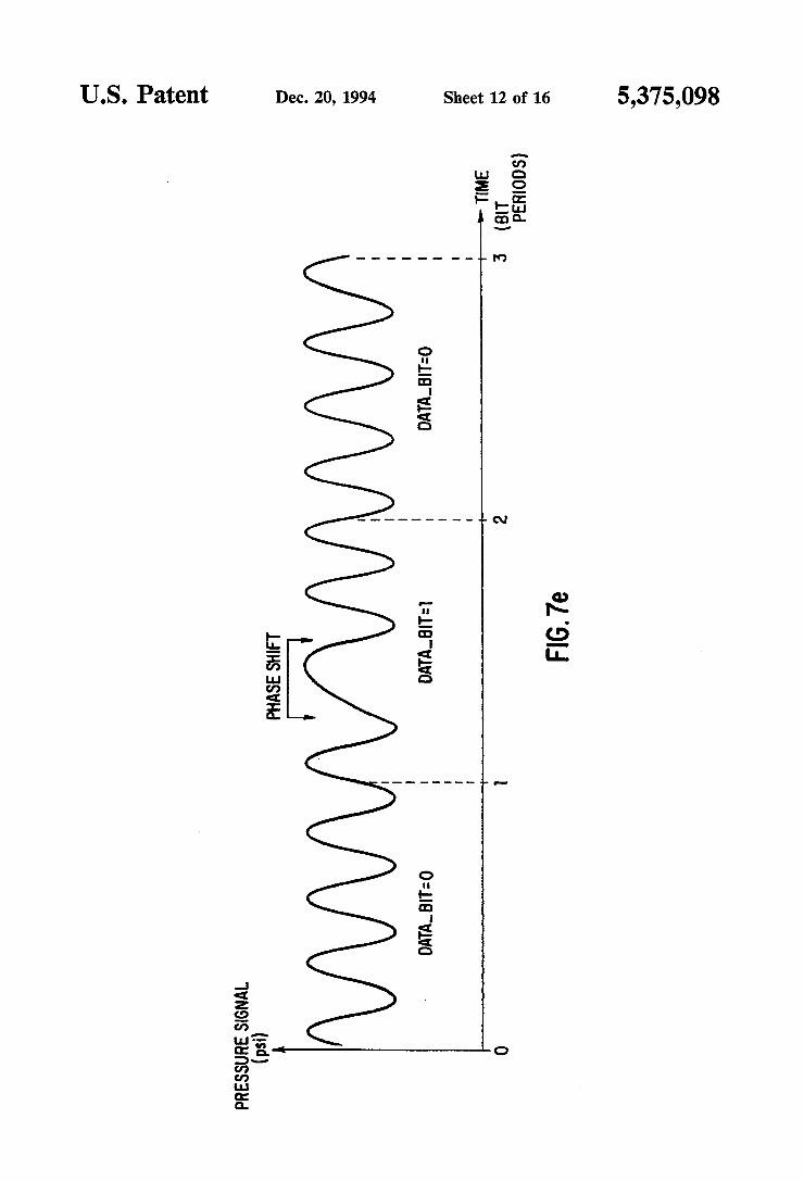
rotor position relative to a magnetic positioner for a phase shift velocity pro?le assisted by the magnetic positioner. FIG. 7e is a graph showing a typical pressure signal
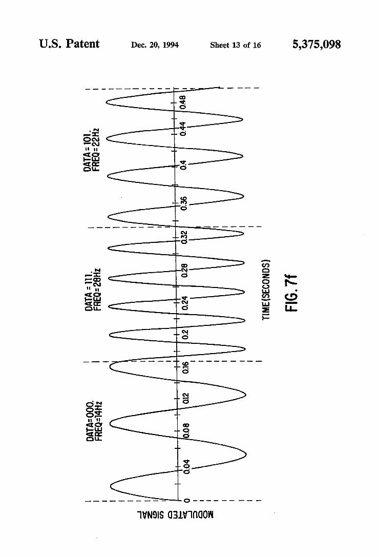
over time of a PSK signal according to the invention. FIG. 7f is a graph showing a typical pressure signal
over time of a FSK signal according to the invention. FIG. 8 is a ?ow chart of the preferred method of the
invention for operating the preferred tool of the inven tion at a desired carrier frequency. FIGS. 9a and 9b are respectively high-level and
lower level software flow diagrams of the anti-jamming software for the microprocessor of FIGS. 2 and 6a.
DETAILED DESCRIPTION OF THE PREFERRED EMBODIMENTS
Referring to FIG. 1, the operation of the present invention in a typical drilling arrangement is illustrated schematically. Drilling mud 10 is picked up from mud pit 11 by one or more mud pumps 12 which are typi cally of the piston reciprocating type. The mud 10 is circulated through mud line 13, down through the drill string 14, through the drill bit 15, and back to the sur face of the formation via the annulus 16 between the drill stem and the wall of the well bore 29. Upon reach ing the earth’s surface 31, the mud is discharged through line 17 back into the mud pit 11 where cuttings of rock or other well debris are allowed to settle out before the mud is recirculated. A downhole pressure pulse signaling device 18 is
incorporated in the drill string for transmission of data signals derived during the drilling operation by the measurement instrument package 19. A preferred rotor and stator for the signaling device which generates sinusoidal signals is discussed hereinafter with reference to FIGS. 3a, 3b, and 4a-4c, although a similar device disclosed in US. Pat. No. 4,847,815 assigned to the assignee hereof may also be utilized. Data signals are encoded in a desired form (also as discussed hereinafter)

5,375,098 5
by appropriate electronic means in the downhole tool. Arrows 21, 22, and 23 illustrate the path taken by the pressure pulses provided by the downhole signaling device 18 under typical well conditions. Pump 12 also produces pressure pulses in the mud line 13 and these are indicated by arrows, 24, 25, 26 and 26a which also illustrate the flow of the mud through the annulus 16.
In order for the downhole pressure pulse signals to be recovered at the surface, some means is preferably pro vided to remove or substantially eliminate the portion of the mud pressure signal due to the mud pumps. Sub system 30, including pressure transducer 32, mud pump piston position sensors 34, and computer or processor 36, comprises one possible such means and is disclosed in detail in copending Ser. No. 07/770,198 which is hereby incorporated by reference herein. Some of the more pertinent details of the LWD tool
50 are seen with reference to FIGS. 2 and 2a-2d. In FIGS. 2a-2d, the tool 50 is seen inside and supported by a drill collar 52. Thus, as seen in FIG. 2a, the tool 50 is provided with a shoulder 54 which supports the tool in the drill collar 52. Also seen in FIG. 2a are a local tool bus extender 56 which provides power and a data link to other sensors. As seen in FIG. 2b, a turbine 58 is provided. The
turbine includes a turbine rotor 60, a turbine stator 62, and a turbine shaft 64. The turbine 58 is driven by the mud circulating through the borehole and the LWD too]. As the mud pushes by the turbine 58, the turbine shaft 64 rotates. The turbine shaft 64 is coupled to an alternator 70 which uses the rotating shaft to generate an electric signal which is recti?ed for driving (power ing) the brushless dc servo motor 100 (see FIG. 2c) and allowing the motor 100 to operate. Turning to FIG. 2, as seen in schematic form, and
located between the alternator 70 (of FIG. 2b) and the motor 100 (of FIG. 2c), are a pressure bulkhead 84, sensors 19 (inclinometers, etc.), an electronics package 90 including a microprocessor 91 (details of which will be discussed hereinafter with reference to FIGS. 6a, 6b, 8, and 9a and 9b), and a pressure compensator 92. The pressure bulkhead 84 and compensator 92 keep the electronics package 90 and sensors 86 at or near atmo spheric pressure so that they may function properly. The brushless dc servo motor 100 which drives the
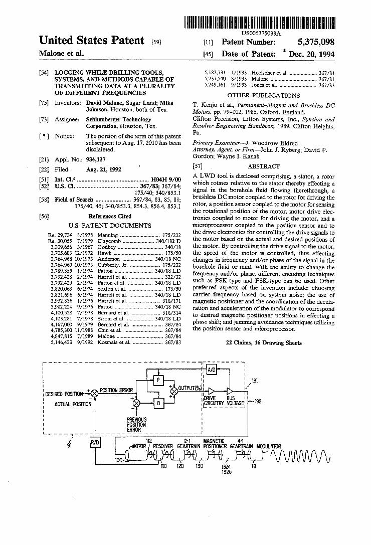
rotor 160 (see FIG. 2:!) of the LWD tool 50 is seen in FIG. 20. In the preferred embodiment, the motor is a motor available from MOOG of East Aurora, N.Y. under part #303F052, and includes a motor shaft/rotor 102, magnets 106, and a motor stator 108. Details of similar types of motors are obtained from Kenjo, T., and Nagamori, S., Permanent-Magnet and Brushless DC Motors (Monographs in Electrical and Electronic Engineering 18); Oxford Science Publications: Clarendon Press (Oxford 1985, pp. 194), which is hereby incorporated by reference herein in its entirety. On the tail end 112 of shaft 102 of the motor is located a position sensor 110 sold under part #JSSBH-lS-C l/Pl37 by the Clifton Precision subsidiary of Litton Systems, Inc., Clifton Heights, Pa. Details of similar types of position sensors are obtained from Engineering Staff of Clifton Precision, “Synchro and Resolver Engi neering Handbook”, Litton Clifton Precision (1989), which is also hereby incorporated by reference herein in its entirety. The function of the position sensor 110 is to determine exactly how far the shaft 102 has rotated. Preferably, position sensor 110 resolves a single rotation
25
35
45
50
60
65
6 of the shaft into four thousand ninety-six counts (twelve bits). The driving end 114 of shaft 102 is coupled to a gear
train 120 which reduces the rotation by a factor of eight. The ?rst gears 122a and 122b of the gear train effect a 2:1 reduction in rotation speed. Located on the shaft 124 coupled to gear 122b is a magnetic positioner 130, dis cussed in detail hereinafter with reference to FIG. 5. The function of the magnetic positioner 130 is to pre vent the modulator 18 (seen in FIG. 2d) from getting stuck in a closed position, and thereby preventing mud from circulating up through the LWD tool and driving the turbine 58. However, according to one aspect of the invention (discussed with reference to FIG. 7/), the arrangement of the magnetic positioner 130 is also used as an aid to the motor causing a modulation in a gener ated signal. As seen in FIG. 20, gear train 120 also includes gears
132a and 132b which effect a further 4:1 reduction in rotation speed of the shaft. Thus, the rotor 160 seen in FIG. 2d, rotates one time for every eight revolutions of the motor 100. Because the rotor 160 (as discussed in more detail with reference to FIGS. 3a, 3b, and 4a—4c) has four lobes, one full rotation of the rotor 160 relative to the stator 150 of FIG. 2d generates a signal approxi mating four sinusoids. With the eight to one reduction, two revolutions of the motor 100 are required to gener ate a single sinusoid from the modulator 18 which in cludes the rotor 160 and stator 150 together. FIGS. 30 and 3b are respectively isometric and front
plan views of the preferred stator 150 of the invention. The stator 150 and the rotor 160 (shown in FIGS. 4a, 4b, and 4c) generally comply with the teachings of US. Pat. No. 4,847,815 and generate sinusoidal waves. In particular, the stator 150 is seen with four lobes 171a, 171b, 171c, and 171d. Each lobe has a ?rst side 152 a second side 154 and an outer edge 156. As seen in FIG. 3b, the ?rst side 152 is radial from the origin 0 of the stator. However, instead of the second side 154 of the lobe being parallel with the ?rst side 152 (as taught in the preferred embodiment of US. Pat. No. 4,847,815), as shown in FIG. 3b, they are at an angle of approxi mately thirteen degrees relative to each other. Also, as shown in FIG. 3b, but seen better in FIG. 3a, the lobes 171 of the stator are undercut at an angle as seen at 158. Turning to FIGS. 40, 4b, and 4c, isometric, front plan,
and side elevational views of the preferred rotor 160 are seen. The rotor 160, as discussed above with reference to FIGS. 2a-2d is coupled to a drive shaft which rotates the rotor 160 relative to the stator 150, thereby generat ing a signal. As with the stator 150, the rotor 160 has four lobes 1720, 172b, 1720, and 172d. Each lobe has a ?rst side 162, a second side 164, and an outer edge 166. As seen in FIG. 4b, the ?rst side 162 is radial from the origin A of the rotor. The second side 166 of the lobe is at an angle of approximately thirteen degrees relative to the ?rst side 164. With the provided geometry of the stator 150 in conjunction with the similar geometry of the rotor 160, when the rotor is at a steady speed, the ori?ce between the rotor and the stator varies in time substantially with the inverse of the square root of a linear function of a sine wave (as discussed in detail in US. Pat. No. 4,847,815). The resulting signal is there fore generally sinusoidal in nature. FIG. 5 is a cross sectional view of the magnetic posi
tioner 130 of FIG. 2c. The magnetic positioner is simply comprised of four sets of magnets 130aS, 130aN, 130bS and 130bN. Two of the four sets of magnets 13008 and