Logbook Control Functions - Agilent · 2020-04-27 · Logbook The Logbook screen is a configurable...
2
Agilent Instant Pilot Quick Reference Guide Functionality For information on other Agilent modules, please refer to the Module’s Manual. Agilent Instant Pilot Quick Reference Guide Functionality Agilent Instant Pilot Quick Reference Guide Functionality For information on other Agilent modules, please refer to the Module’s Manual. For information on other Agilent modules, please refer to the Module’s Manual. Method General The screen displays complete or filtered method setpoints of all modules. Depending on the number of modules, you may have to scroll through the display. To edit a parameter, select it using the arrow up / down buttons and press Edit or OK key. Functions: Filters opens a screen to setup a filter to control the visibility of the parameters in the method screen. The filter is stored with the method. Compare two methods. The differences are shown in a list by displaying the values from both methods. Timetable opens a screen showing the timetable programmed parameters. The timetable can be edited in the timetable screen and is stored together with the method. Properties of a method can be reviewed in the Properties screen. You can view changes and the reasons for them. File: Method parameter sets can be accessed from the internal flash disc or on a USB Flash Drive, can be imported from the old Control Module or edited offline. Toggle: switches between filtered and unfiltered view. Sequence General A sequence consists of a list of items that should be processed sequentially. The items are inserted in the list using the Insert button or, in the case of samples and calibration samples, by using the wizard. The Sequence can be edited using the Edit or OK key, Delete or Copy buttons. Functions: Edit or OK key allows changes to a selected sequence line. Insert opens a menu containing elements to insert into the sequence list before the selected line. Delete/Copy/Paste deletes/copies/pastes a selected sequence line. Wizard allows easy definition of sample ranges and calibration processing. It starts with the input of the location. File Sequence parameter sets can be accessed from the internal flash disc or a USB Flash Drive using the file dialog box. Tray View shows the current sequence's status graphically. The sequence samples are shown at their locations on the tray using colors representing their states and purpose (sample/calib.). Status General The Status screen is a configurable overview of the instrument status. You can view actual values/states and edit parameters. The screen is divided into four tiles. Each tile itself can also hold up to four smaller tiles. The Instant Pilot automatically chooses the size of the tiles based on the selection. Large tiles can hold signal plots Functions: Plot shows different signals of the connected modules over time. The signals are user-selectable, can automatically be rescaled for best on-screen fitting. Setup lets you set up the views. A Default button loads a pre-defined view (depends on system). Select lets you choose to load one of the last 4 setups. Logbook General The Logbook screen is a configurable overview of the information, internal sequences, error, maintenance, system and Early Maintenance Feedback (EMF) messages. Functions: Filters allows the configuration of the view Print allows the screen to be printed to a USB Flash Drive for storage or printing via a PC. System shows all entries of all modules, the module specific buttons a single module's logbook. Details (System Info) General All modules of the system are listed with serial number, firmware revision and on-time. Functions: Print allows the printing of the screen to a USB Flash Drive for storage or print via a PC. Plot (via Status) General The Plot screen gives you many opportunities to display a wide variety of signals on a graphic display while the analysis is ongoing or otherwise. The plot screen can show different signals of the connected modules over time. The signals are user-selectable, and can automatically be rescaled to optimize the viewing area. Functions: Setup to select the signals of interest. Rescale to maximize the signals of interest. Select to make a signal active on the Y-axis or use the number keys 1, 2, 3 or 4. Print to print the plot window to the USB Flash Drive. Direction keys to change the Y-range (up/down) or the time scale (left/right). Control Functions General All control menu items directly trigger a day-to-day action on the instrument outside an analysis. The control menu can be opened in major screens via the Control button. Typical functions are detector balancing, or getting the instrument in a “ready for analysis” state. Functions: On/Off screen for easy and visual turn on/off of modules. Get Ready performs all required actions to bring a system into a ready state. Clear Errors clears all errors in the modules, if the error cause is eliminated (see also Control-Get Ready). Set Defaults resets all module's method parameters to factory defaults. Scan (DAD/MWD/VWD/FLD) spectrum. Start Analysis (pressing Start) General The Start Analysis screen allows an analysis to be set up: • Setup a simple vial range and the method to be used • Select the currently loaded sequence • Resume a paused sequence • Blank run • Start from selected line The selected action will get started by pressing continue, cancel closes the start dialog without starting analysis. Note: If the system is in not-ready state, the Instant Pilot brings up the System On/ Off screen. Follow the instructions on that screen and the Start is executed as soon as the System is in Ready state. Configuration (via More) General These parameters allow the setup of the instrument configuration. Typically, these configurations are linked to properties of the instrument (e.g. module names, flow path volumes, analog output configuration, LAN address) that are set up only at installation or after modification of the instrument setup. Functions: Edit or OK key allows changes of the select parameter. Setup (System only) starts the Setup Wizard and allows the setting of Date & Time, Instrument Name, Unit- and Formats, Display and LAN interface.
Transcript of Logbook Control Functions - Agilent · 2020-04-27 · Logbook The Logbook screen is a configurable...
Agilent Instant Pilot Quick Reference Guide Functionality
For information on other Agilent modules, please refer to the Module’s Manual.
Agilent Instant Pilot Quick Reference Guide Functionality Agilent Instant Pilot Quick Reference Guide Functionality
For information on other Agilent modules, please refer to the Module’s Manual. For information on other Agilent modules, please refer to the Module’s Manual.
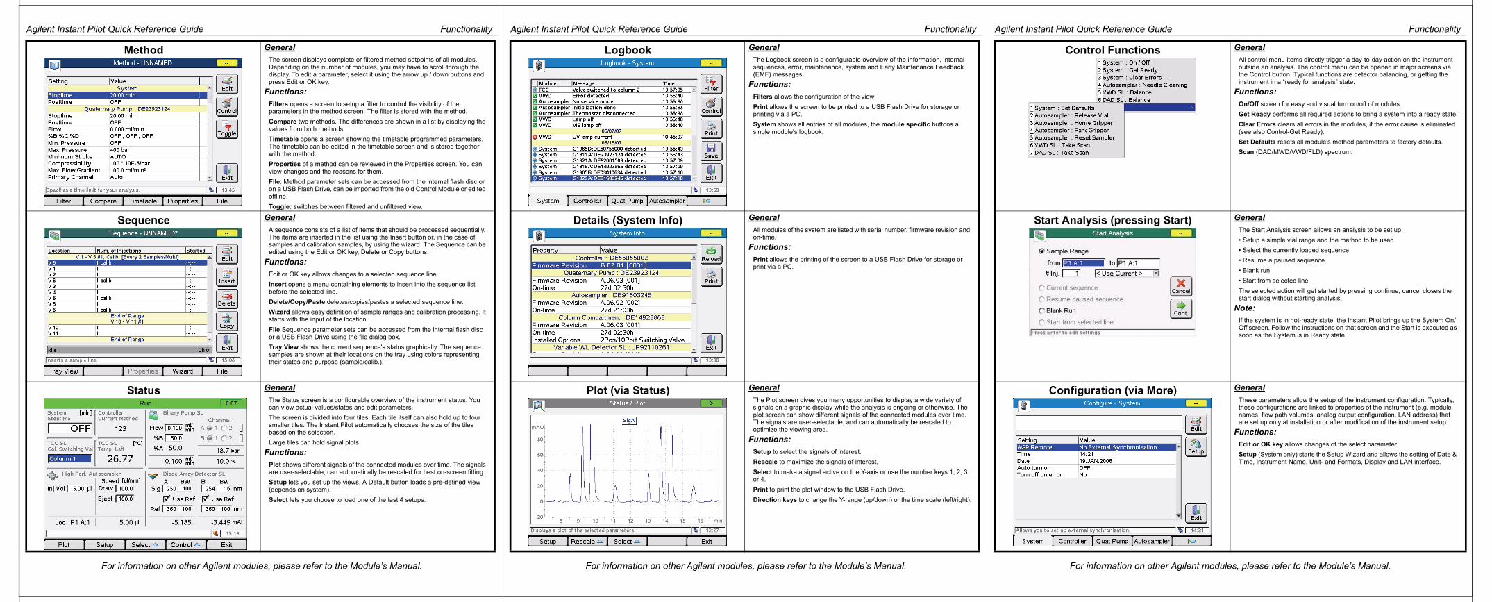
Method GeneralThe screen displays complete or filtered method setpoints of all modules. Depending on the number of modules, you may have to scroll through the display. To edit a parameter, select it using the arrow up / down buttons and press Edit or OK key.
Functions:Filters opens a screen to setup a filter to control the visibility of the parameters in the method screen. The filter is stored with the method.
Compare two methods. The differences are shown in a list by displaying the values from both methods.
Timetable opens a screen showing the timetable programmed parameters. The timetable can be edited in the timetable screen and is stored together with the method.
Properties of a method can be reviewed in the Properties screen. You can view changes and the reasons for them.
File: Method parameter sets can be accessed from the internal flash disc or on a USB Flash Drive, can be imported from the old Control Module or edited offline.
Toggle: switches between filtered and unfiltered view.
Sequence GeneralA sequence consists of a list of items that should be processed sequentially. The items are inserted in the list using the Insert button or, in the case of samples and calibration samples, by using the wizard. The Sequence can be edited using the Edit or OK key, Delete or Copy buttons.
Functions:Edit or OK key allows changes to a selected sequence line.
Insert opens a menu containing elements to insert into the sequence list before the selected line.
Delete/Copy/Paste deletes/copies/pastes a selected sequence line.
Wizard allows easy definition of sample ranges and calibration processing. It starts with the input of the location.
File Sequence parameter sets can be accessed from the internal flash disc or a USB Flash Drive using the file dialog box.
Tray View shows the current sequence's status graphically. The sequence samples are shown at their locations on the tray using colors representing their states and purpose (sample/calib.).
Status GeneralThe Status screen is a configurable overview of the instrument status. You can view actual values/states and edit parameters.
The screen is divided into four tiles. Each tile itself can also hold up to four smaller tiles. The Instant Pilot automatically chooses the size of the tiles based on the selection.
Large tiles can hold signal plots
Functions:Plot shows different signals of the connected modules over time. The signals are user-selectable, can automatically be rescaled for best on-screen fitting.
Setup lets you set up the views. A Default button loads a pre-defined view (depends on system).
Select lets you choose to load one of the last 4 setups.
Logbook GeneralThe Logbook screen is a configurable overview of the information, internal sequences, error, maintenance, system and Early Maintenance Feedback (EMF) messages.
Functions:Filters allows the configuration of the view
Print allows the screen to be printed to a USB Flash Drive for storage or printing via a PC.
System shows all entries of all modules, the module specific buttons a single module's logbook.
Details (System Info) GeneralAll modules of the system are listed with serial number, firmware revision and on-time.
Functions:Print allows the printing of the screen to a USB Flash Drive for storage or print via a PC.
Plot (via Status) GeneralThe Plot screen gives you many opportunities to display a wide variety of signals on a graphic display while the analysis is ongoing or otherwise. The plot screen can show different signals of the connected modules over time. The signals are user-selectable, and can automatically be rescaled to optimize the viewing area.
Functions:Setup to select the signals of interest.
Rescale to maximize the signals of interest.
Select to make a signal active on the Y-axis or use the number keys 1, 2, 3 or 4.
Print to print the plot window to the USB Flash Drive.
Direction keys to change the Y-range (up/down) or the time scale (left/right).
Control Functions GeneralAll control menu items directly trigger a day-to-day action on the instrument outside an analysis. The control menu can be opened in major screens via the Control button. Typical functions are detector balancing, or getting the instrument in a “ready for analysis” state.
Functions:On/Off screen for easy and visual turn on/off of modules.
Get Ready performs all required actions to bring a system into a ready state.
Clear Errors clears all errors in the modules, if the error cause is eliminated (see also Control-Get Ready).
Set Defaults resets all module's method parameters to factory defaults.
Scan (DAD/MWD/VWD/FLD) spectrum.
Start Analysis (pressing Start) GeneralThe Start Analysis screen allows an analysis to be set up:
• Setup a simple vial range and the method to be used
• Select the currently loaded sequence
• Resume a paused sequence
• Blank run
• Start from selected line
The selected action will get started by pressing continue, cancel closes the start dialog without starting analysis.
Note:If the system is in not-ready state, the Instant Pilot brings up the System On/Off screen. Follow the instructions on that screen and the Start is executed as soon as the System is in Ready state.
Configuration (via More) GeneralThese parameters allow the setup of the instrument configuration. Typically, these configurations are linked to properties of the instrument (e.g. module names, flow path volumes, analog output configuration, LAN address) that are set up only at installation or after modification of the instrument setup.
Functions:Edit or OK key allows changes of the select parameter.
Setup (System only) starts the Setup Wizard and allows the setting of Date & Time, Instrument Name, Unit- and Formats, Display and LAN interface.
Agilent Instant Pilot Quick Reference Guide Functionality
For information on other Agilent modules, please refer to the Module’s Manual.
Agilent Instant Pilot Quick Reference Guide Functionality
*G4208-90007**G4208-90007*G4208-90007 For information on other Agilent modules, please refer to the Module’s Manual.
© Agilent Technologies 2007-2010
Printed in Malaysia06/10
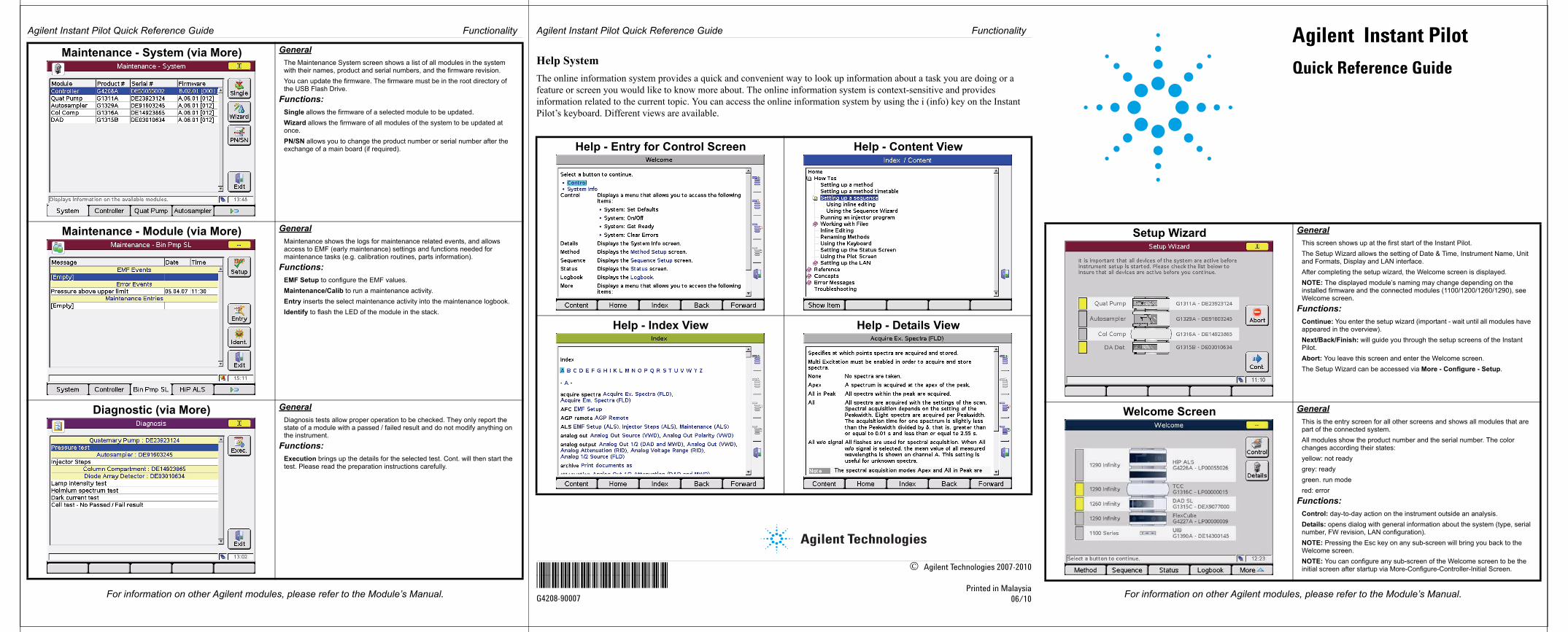
Help SystemThe online information system provides a quick and convenient way to look up information about a task you are doing or a feature or screen you would like to know more about. The online information system is context-sensitive and provides information related to the current topic. You can access the online information system by using the i (info) key on the Instant Pilot’s keyboard. Different views are available.
Maintenance - System (via More) GeneralThe Maintenance System screen shows a list of all modules in the system with their names, product and serial numbers, and the firmware revision.
You can update the firmware. The firmware must be in the root directory of the USB Flash Drive.
Functions:Single allows the firmware of a selected module to be updated.
Wizard allows the firmware of all modules of the system to be updated at once.
PN/SN allows you to change the product number or serial number after the exchange of a main board (if required).
Maintenance - Module (via More) GeneralMaintenance shows the logs for maintenance related events, and allows access to EMF (early maintenance) settings and functions needed for maintenance tasks (e.g. calibration routines, parts information).
Functions:EMF Setup to configure the EMF values.
Maintenance/Calib to run a maintenance activity.
Entry inserts the select maintenance activity into the maintenance logbook.
Identify to flash the LED of the module in the stack.
Diagnostic (via More) GeneralDiagnosis tests allow proper operation to be checked. They only report the state of a module with a passed / failed result and do not modify anything on the instrument.
Functions:Execution brings up the details for the selected test. Cont. will then start the test. Please read the preparation instructions carefully.
Help - Entry for Control Screen Help - Content View
Help - Index View Help - Details View
Setup Wizard GeneralThis screen shows up at the first start of the Instant Pilot.
The Setup Wizard allows the setting of Date & Time, Instrument Name, Unit and Formats, Display and LAN interface.
After completing the setup wizard, the Welcome screen is displayed.
NOTE: The displayed module’s naming may change depending on the installed firmware and the connected modules (1100/1200/1260/1290), see Welcome screen.
Functions:Continue: You enter the setup wizard (important - wait until all modules have appeared in the overview).
Next/Back/Finish: will guide you through the setup screens of the Instant Pilot.
Abort: You leave this screen and enter the Welcome screen.
The Setup Wizard can be accessed via More - Configure - Setup.
Welcome Screen GeneralThis is the entry screen for all other screens and shows all modules that are part of the connected system.
All modules show the product number and the serial number. The color changes according their states:
yellow: not ready
grey: ready
green. run mode
red: error
Functions:Control: day-to-day action on the instrument outside an analysis.
Details: opens dialog with general information about the system (type, serial number, FW revision, LAN configuration).
NOTE: Pressing the Esc key on any sub-screen will bring you back to the Welcome screen.
NOTE: You can configure any sub-screen of the Welcome screen to be the initial screen after startup via More-Configure-Controller-Initial Screen.
Agilent Instant Pilot
Quick Reference Guide