Lodge II Pergola - Pergola Kits USA · Lodge II Pergola Manual and Installation Instructions Please...
14
Lodge II Pergola Manual and Installation Instructions Please read these instructions before removing parts from crate
Transcript of Lodge II Pergola - Pergola Kits USA · Lodge II Pergola Manual and Installation Instructions Please...
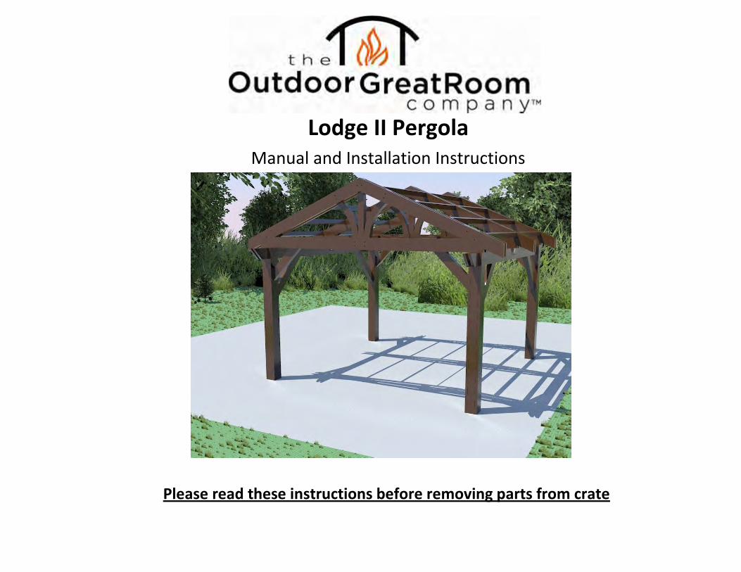
Lodge II Pergola Manual and Installation Instructions
Please read these instructions before removing parts from crate
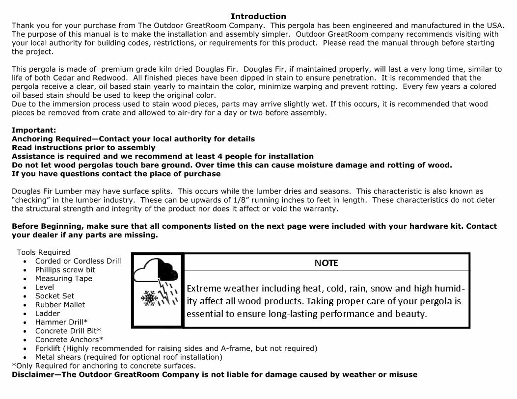
Introduction Thank you for your purchase from The Outdoor GreatRoom Company. This pergola has been engineered and manufactured in the USA. The purpose of this manual is to make the installation and assembly simpler. Outdoor GreatRoom company recommends visiting with your local authority for building codes, restrictions, or requirements for this product. Please read the manual through before starting
the project.
This pergola is made of premium grade kiln dried Douglas Fir. Douglas Fir, if maintained properly, will last a very long time, similar to life of both Cedar and Redwood. All finished pieces have been dipped in stain to ensure penetration. It is recommended that the pergola receive a clear, oil based stain yearly to maintain the color, minimize warping and prevent rotting. Every few years a colored
oil based stain should be used to keep the original color. Due to the immersion process used to stain wood pieces, parts may arrive slightly wet. If this occurs, it is recommended that wood
pieces be removed from crate and allowed to air-dry for a day or two before assembly. Important:
Anchoring Required—Contact your local authority for details Read instructions prior to assembly
Assistance is required and we recommend at least 4 people for installation Do not let wood pergolas touch bare ground. Over time this can cause moisture damage and rotting of wood. If you have questions contact the place of purchase
Douglas Fir Lumber may have surface splits. This occurs while the lumber dries and seasons. This characteristic is also known as
“checking” in the lumber industry. These can be upwards of 1/8” running inches to feet in length. These characteristics do not deter the structural strength and integrity of the product nor does it affect or void the warranty.
Before Beginning, make sure that all components listed on the next page were included with your hardware kit. Contact your dealer if any parts are missing.
Tools Required
Corded or Cordless Drill
Phillips screw bit Measuring Tape
Level Socket Set
Rubber Mallet Ladder Hammer Drill*
Concrete Drill Bit* Concrete Anchors*
Forklift (Highly recommended for raising sides and A-frame, but not required) Metal shears (required for optional roof installation)
*Only Required for anchoring to concrete surfaces.
Disclaimer—The Outdoor GreatRoom Company is not liable for damage caused by weather or misuse
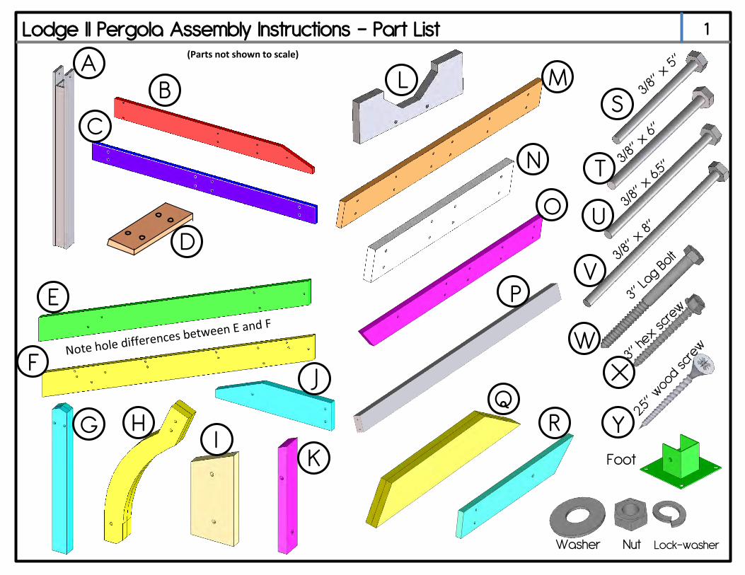
Lodge II Pergola Assembly Instructions – Part List
U
T
S
R Q
P
O
N
M
I
L
F
K
E
J
D
H
C
G
B A
Y
X
W
V
Washer Nut Lock-washer
(Parts not shown to scale)
1
Foot
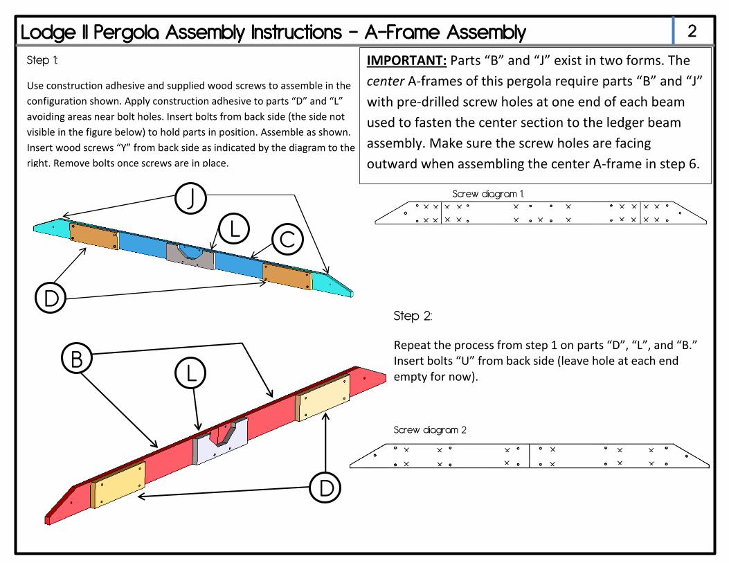
2 Lodge II Pergola Assembly Instructions – A-Frame Assembly
Step 1:
Use construction adhesive and supplied wood screws to assemble in the
configuration shown. Apply construction adhesive to parts “D” and “L”
avoiding areas near bolt holes. Insert bolts from back side (the side not
visible in the figure below) to hold parts in position. Assemble as shown.
Insert wood screws “Y” from back side as indicated by the diagram to the
right. Remove bolts once screws are in place.
D
L C
J x
x
x
x
x
x
x
x
x
x
x
x
x
x
x
x
x
x x x
x
Screw diagram 2
Step 2:
Repeat the process from step 1 on parts “D”, “L”, and “B.” Insert bolts “U” from back side (leave hole at each end empty for now).
D
L B
x x
x x
x
x
x
x x
x x
x
Screw diagram 1.
IMPORTANT: Parts “B” and “J” exist in two forms. The
center A-frames of this pergola require parts “B” and “J”
with pre-drilled screw holes at one end of each beam
used to fasten the center section to the ledger beam
assembly. Make sure the screw holes are facing
outward when assembling the center A-frame in step 6.
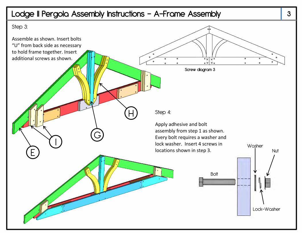
Lodge II Pergola Assembly Instructions – A-Frame Assembly 3
Step 3:
Assemble as shown. Insert bolts “U” from back side as necessary to hold frame together. Insert additional screws as shown.
E
G
H
I
x x x x
Bolt
Washer
Lock-Washer
Nut
Step 4:
Apply adhesive and bolt assembly from step 1 as shown. Every bolt requires a washer and lock washer. Insert 4 screws in locations shown in step 3.
Screw diagram 3
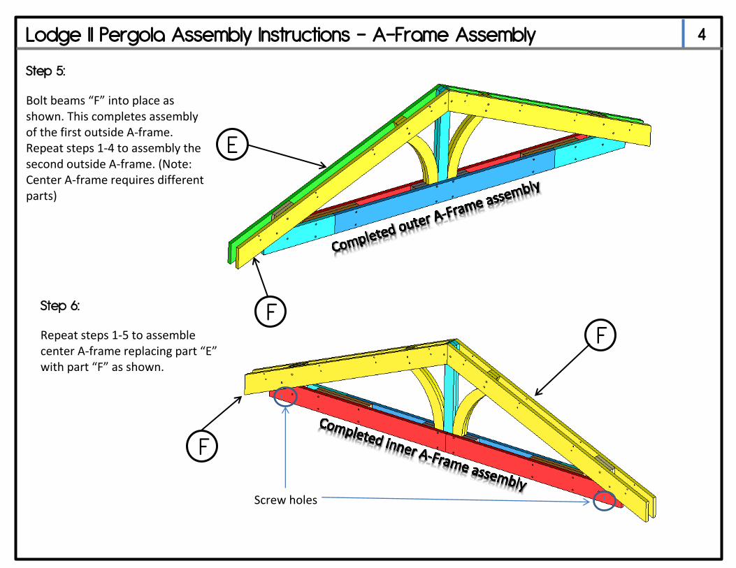
Lodge II Pergola Assembly Instructions – A-Frame Assembly 4
Step 5:
Bolt beams “F” into place as shown. This completes assembly of the first outside A-frame. Repeat steps 1-4 to assembly the second outside A-frame. (Note: Center A-frame requires different parts)
Step 6:
Repeat steps 1-5 to assemble center A-frame replacing part “E” with part “F” as shown.
F F
F
E
Screw holes
Lodge II Pergola Assembly Instructions – Ledger Beam Assembly 5
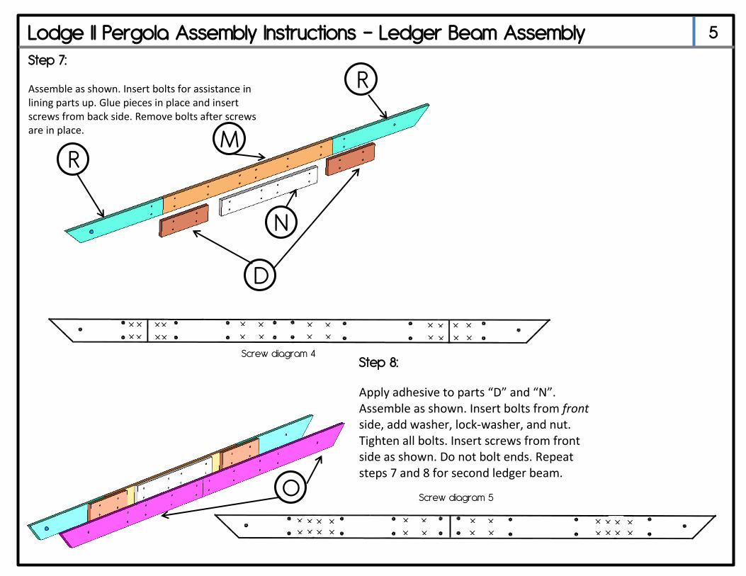
Step 7:
Assemble as shown. Insert bolts for assistance in lining parts up. Glue pieces in place and insert screws from back side. Remove bolts after screws are in place.
M
N
D
R
R
x x
x x
x x
x x
x x
x x
x
x x
x
x
x
x
x
x
x
x
Step 8:
Apply adhesive to parts “D” and “N”. Assemble as shown. Insert bolts from front side, add washer, lock-washer, and nut. Tighten all bolts. Insert screws from front side as shown. Do not bolt ends. Repeat steps 7 and 8 for second ledger beam.
Screw diagram 4
Screw diagram 5
x
x
x x x
x x
x x x
x x x
x x
x x x x
x x
x x
x x
O
Lodge II Pergola Assembly Instructions – Column Assembly 6
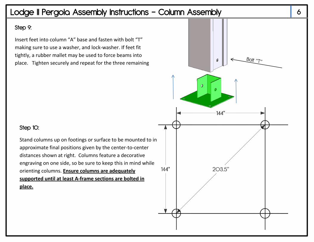
Step 9:
Insert feet into column “A” base and fasten with bolt “T”
making sure to use a washer, and lock-washer. If feet fit
tightly, a rubber mallet may be used to force beams into
place. Tighten securely and repeat for the three remaining
columns.
Step 10:
Stand columns up on footings or surface to be mounted to in
approximate final positions given by the center-to-center
distances shown at right. Columns feature a decorative
engraving on one side, so be sure to keep this in mind while
orienting columns. Ensure columns are adequately
supported until at least A-frame sections are bolted in
place.
Lodge II Pergola Assembly Instructions – Main Assembly 7
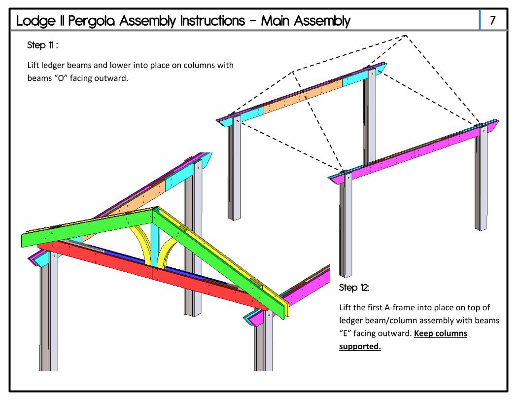
Step 11 :
Lift ledger beams and lower into place on columns with
beams “O” facing outward.
Step 12:
Lift the first A-frame into place on top of
ledger beam/column assembly with beams
“E” facing outward. Keep columns
supported.
Lodge II Pergola Assembly Instructions – Main Assembly 8
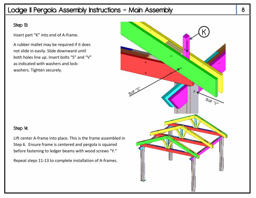
Step 13:
Insert part “K” into end of A-frame.
A rubber mallet may be required if it does
not slide in easily. Slide downward until
both holes line up. Insert bolts “S” and “V”
as indicated with washers and lock-
washers. Tighten securely.
K
Step 14:
Lift center A-frame into place. This is the frame assembled in
Step 6. Ensure frame is centered and pergola is squared
before fastening to ledger beams with wood screws “Y.”
Repeat steps 11-13 to complete installation of A-frames.
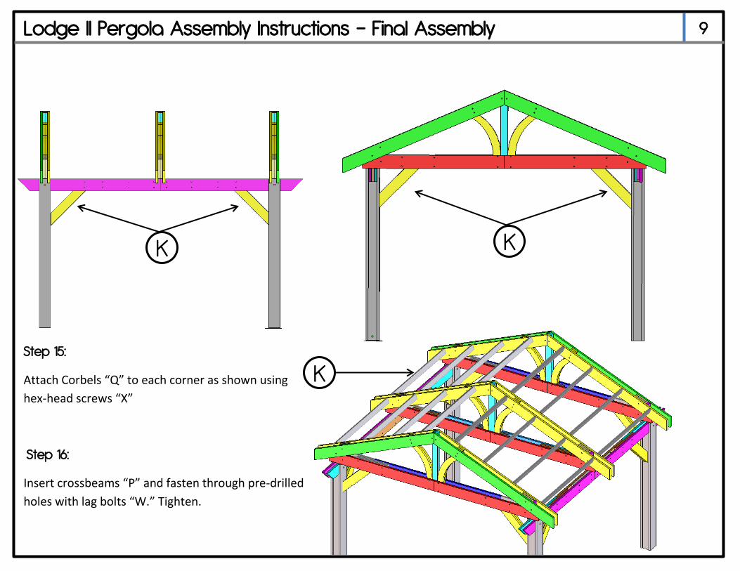
Lodge II Pergola Assembly Instructions – Final Assembly 9
Step 15:
Attach Corbels “Q” to each corner as shown using
hex-head screws “X”
Step 16:
Insert crossbeams “P” and fasten through pre-drilled
holes with lag bolts “W.” Tighten.
K
K
K
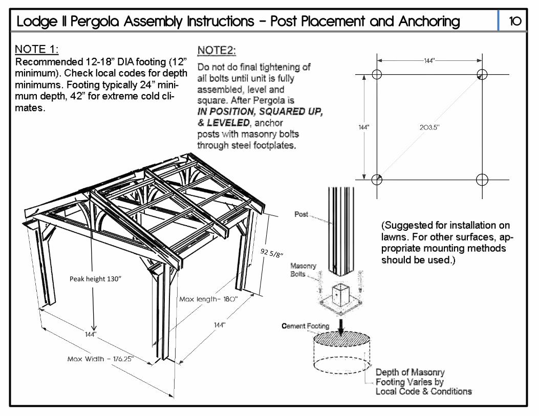
Lodge II Pergola Assembly Instructions – Post Placement and Anchoring 10
Peak height 130”
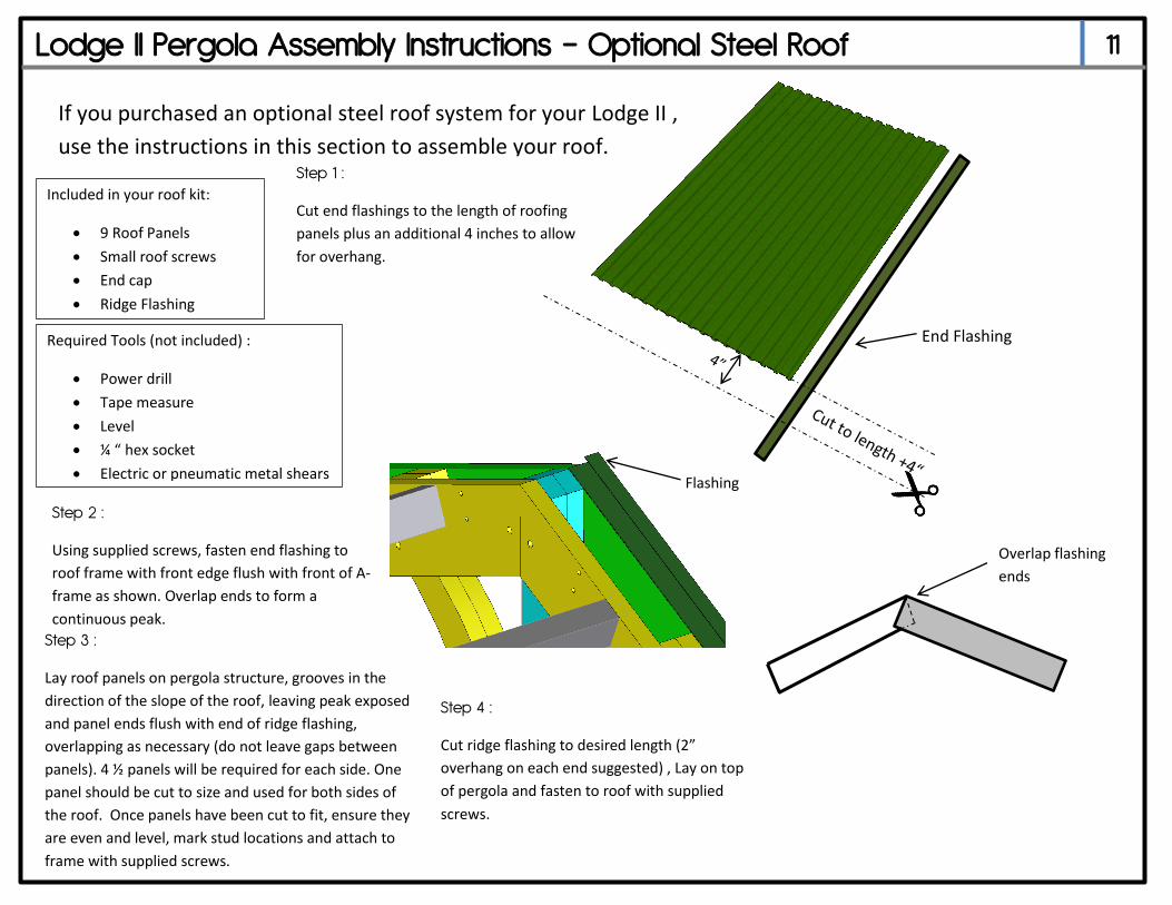
Lodge II Pergola Assembly Instructions – Optional Steel Roof 11
If you purchased an optional steel roof system for your Lodge II ,
use the instructions in this section to assemble your roof.
Included in your roof kit:
9 Roof Panels
Small roof screws
End cap
Ridge Flashing
Step 1 :
Cut end flashings to the length of roofing
panels plus an additional 4 inches to allow
for overhang.
End Flashing
Step 3 :
Lay roof panels on pergola structure, grooves in the
direction of the slope of the roof, leaving peak exposed
and panel ends flush with end of ridge flashing,
overlapping as necessary (do not leave gaps between
panels). 4 ½ panels will be required for each side. One
panel should be cut to size and used for both sides of
the roof. Once panels have been cut to fit, ensure they
are even and level, mark stud locations and attach to
frame with supplied screws.
Step 2 :
Using supplied screws, fasten end flashing to
roof frame with front edge flush with front of A-
frame as shown. Overlap ends to form a
continuous peak.
Flashing
Required Tools (not included) :
Power drill
Tape measure
Level
¼ “ hex socket
Electric or pneumatic metal shears
Overlap flashing
ends
Step 4 :
Cut ridge flashing to desired length (2”
overhang on each end suggested) , Lay on top
of pergola and fasten to roof with supplied
screws.
Lodge II Pergola Assembly Instructions - Warranty Info 12
Lodge II Pergola Warranty Information
Your new Lodge II pergola is warranted against structural defects for a period of three (3) years from the date of purchase. This does not apply to damage caused by
excessive loads such as snow or use of roof as storage. Your Lodge II pergola is warranted against defects in finish and other defects not related to structure for a period of one (1) year from the date of purchase. All metal hardware must be sprayed with a clear lacquer sealer once your pergola is assembled to prevent rust and
corrosion. The Outdoor Greatroom Company extends the following warranty for Outdoor Greatroom outdoor products used in the United States of America or Canada.
Dealers and employees of The Outdoor Greatroom Company have no authority to make any warranty or authorize any remedies in addition to or inconsistent with the terms of this warranty. This warranty gives you specific legal rights. You may also have other rights that vary from state to state.
The Outdoor Greatroom Company warrants that this Outdoor Greatroom Outdoor Product (the “Product”) will be free from defects in material and workmanship for a period of one (1) year for finish and other non-structural defects and three (3) years from its date of purchase structurally. This warranty is subject to the conditions, exclusions and limitations described below.
This warranty applies only to the original owner of the Product and is non-transferable. The Outdoor Greatroom Company obligation under this warranty does not extend to damages resulting from (1) assembly, operation or maintenance of the Product not in accordance with the Installation/Assembly Instructions, Operating Instruc-tions and the Listing Agency Identification Label furnished with the Product; (2) installation or use which does not comply with local building codes and ordinances; (3) shipping, improper handling, improper operation, abuse, misuse, accident or unworkmanlike repairs; (4) use of fuels other than those specified in the Operating Instructions; (5) Installation or use of components not supplied with the Product or any other components not expressly authorized and approved in writing by The Outdoor Greatroom Company; and/or (6) modification of the Product not expressly authorized and approved in writing by The Outdoor Greatroom Company. Any of the circumstances described in the previous sentence voids this warranty. This warranty is void if the Product or any component has been removed, repaired, or replaced before The Outdoor Greatroom Company has been afforded a reasonable opportunity to inspect the Product.
This warranty is limited to the replacement or repair of defective components or workmanship and The Outdoor Greatroom Company may fully discharge its obligations under this warranty by repairing or replacing, at its discretion, the defective components. The Outdoor Greatroom Company will provide replacement parts at no charge and will pay reasonable and necessary labor and freight costs related to replacing or repairing defective components under this warranty. The maximum amount recoverable under this warranty is limited to the pur-chase price of the Product and, if The Outdoor Greatroom Company is unable to provide replacement or repair in an expedient and cost-effective manner, The Outdoor Greatroom Company may discharge all obligations under this warranty by refunding the purchase price of the Product.
EXCEPT TO THE EXTENT PROVIDED BY LAW, THE OUTDOOR GREATROOM COMPANY MAKES NO EXPRESS WARRANTIES OTHER THAN THE WARRANTY EXPRESSED HEREIN. THE DURATION OF ANY IMPLIED WARRANTY IS LIMITED TO THE DURATION OF THE WARRANTY SPECIFIED ABOVE. IN NO EVENT SHALL THE OUTDOOR GREATROOM COMPANY BE LIABLE FOR ANY INCIDENTAL OR CONSE-QUENTIAL DAMAGES CAUSED BY DEFECTS IN THE PRODUCT. Some states do not allow limitations on how long an implied warranty lasts, or do not allow exclusion or limitation of incidental or consequential dam-ages, so these limitations may not apply to you.
Send written notice of the claimed condition to: The Outdoor Greatroom Company, 2015 Silver Bell Road, #195, Eagan, MN 55122.
Affirm that you are the original owner of the Product.
Provide The Outdoor Greatroom Company reasonable opportunity to investigate the claim, including reasonable opportunity to inspect the Product prior to any repair or replacement work and before the Product or any component of the Product has been removed.
Obtain The Outdoor Greatroom Company’s consent to any warranty work before the work is done. © The Outdoor Greatroom Company