LOD Spec 2017 Part I - BIMForumbimforum.org/.../LOD-Spec-2017-Part-I-2017-11-07-1.pdf · LOD Spec...
231
20 17 LEVEL OF DEVELOPMENT SPECIFICATION PART I November 2017 Copyright © 2017 BIM Forum PARTICIPATING ORGANIZATIONS
Transcript of LOD Spec 2017 Part I - BIMForumbimforum.org/.../LOD-Spec-2017-Part-I-2017-11-07-1.pdf · LOD Spec...

20 17
LEVEL OF DEVELOPMENT SPECIFICATION PART I November 2017
Copyright © 2017 BIM Forum
PARTICIPATING ORGANIZATIONS

LOD Spec 2017 Part I
Version: 2017
November 2017
For Building Information Models
Nothing contained in this work shall be considered the rendering of legal advice. Readers are responsible for obtaining such advice from their own legal counsel. This work and any forms herein are intended solely for educational and informational purposes. All images are intended to illustrate building conditions in compliance with common building codes. However, the images do not take into account site specific conditions, regional building codes and other important information that may require a material change for specific projects. These illustrations do not make representation for fitness for a particular project nor for code or design compliance. Copyright © 2017 by BIMForum. All rights reserved The LOD Specification Part I and Part II as well as the LOD Specification Guide are made available to the public without charge. In order to maintain the integrity and usefulness of these documents as a reference standard, certain restrictions apply to their use. These documents are licensed to the public under Creative Commons licenses as follows:
Part I of this work is licensed under the Creative Commons Attribution-NonCommercial-NoDerivatives 4.0 International License (http://creativecommons.org/licenses/by-nc-nd/4.0/). Part II of this work is licensed under the Creative Commons Attribution-NonCommercial 4.0 International License (http://creativecommons.org/licenses/by-nc/4.0/). The LOD Spec Guide is licensed under the Creative Commons Attribution-NonCommercial-NoDerivatives 4.0 International License (http://creativecommons.org/licenses/by-nc-nd/4.0/). Licensing questions should be directed to [email protected].

Level of Development Specification Version: 2017
www.bimforum.org/lod
Back to TOC Copyright © 2017 by BIMForum. All rights reserved 2
This document is copyrighted under a Creative Commons Attribution-NonCommercial-NoDerivatives 4.0 International License.
ACKNOWLEDGEMENTS
Many thanks to all the individuals and organizations who reviewed and contributed to this work, and to the following industry association representatives and co-chairs of the major discipline subgroups who made this document possible:
Overall Co-Chairs
Jan Reinhardt, Adept Project Delivery
Jim Bedrick, FAIA, AEC Process Engineering
Domain Co-Chairs
Design Construction
Structures
Will Ikerd, PE, LEED AP IKERD Consulting, LLC
David Merrifield Steel Fab, Inc.
Exterior Skin
James Vandezande, AIA HOK
Jon McFarland Wheaton Sprague
Interior Construction
Ron Dellaria, AIA, CSI Collaborative Construction Consultants
Brian Filkins The Beck Group
Conveying
Brian Skripac, Assoc. AIA, LEED AP BD+C Cannon Design
Ken Flannigan, LEED AP KONE
Building Services
Birgitta Foster VDCO Tech
David Francis Murray Company
Civil
Will Ikerd, PE, LEED AP IKERD Consulting, LLC
Gregg Madsen, RPLS Wier & Associates, Inc.
Bridge: Highway & Rail
Will Ikerd, PE, LEED AP IKERD Consulting, LLC
David Merrifield Steel Fab, Inc.
Legal
Carl G. Roberts, Law Offices of Carl G. Roberts LLC
Industry Association Representatives
Dmitri Alferieff, Associated General Contractors
Michael Bomba, Esq., American Institute of Architects
Level of Development Specification Version: 2017
www.bimforum.org/lod
Back to TOC Copyright © 2017 by BIMForum. All rights reserved 3
This document is copyrighted under a Creative Commons Attribution-NonCommercial-NoDerivatives 4.0 International License.
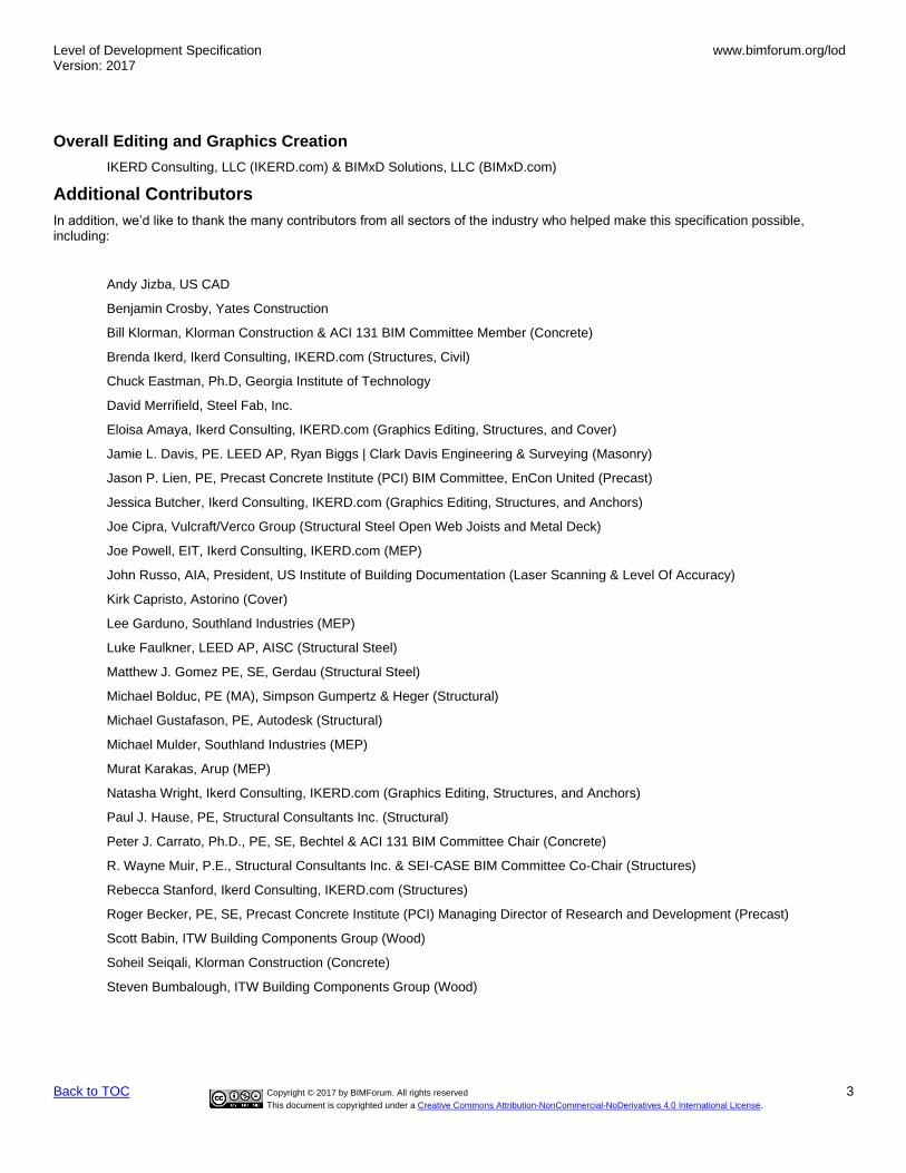
Overall Editing and Graphics Creation
IKERD Consulting, LLC (IKERD.com) & BIMxD Solutions, LLC (BIMxD.com)
Additional Contributors
In addition, we’d like to thank the many contributors from all sectors of the industry who helped make this specification possible, including:
Andy Jizba, US CAD
Benjamin Crosby, Yates Construction
Bill Klorman, Klorman Construction & ACI 131 BIM Committee Member (Concrete)
Brenda Ikerd, Ikerd Consulting, IKERD.com (Structures, Civil)
Chuck Eastman, Ph.D, Georgia Institute of Technology
David Merrifield, Steel Fab, Inc.
Eloisa Amaya, Ikerd Consulting, IKERD.com (Graphics Editing, Structures, and Cover)
Jamie L. Davis, PE. LEED AP, Ryan Biggs | Clark Davis Engineering & Surveying (Masonry)
Jason P. Lien, PE, Precast Concrete Institute (PCI) BIM Committee, EnCon United (Precast)
Jessica Butcher, Ikerd Consulting, IKERD.com (Graphics Editing, Structures, and Anchors)
Joe Cipra, Vulcraft/Verco Group (Structural Steel Open Web Joists and Metal Deck)
Joe Powell, EIT, Ikerd Consulting, IKERD.com (MEP)
John Russo, AIA, President, US Institute of Building Documentation (Laser Scanning & Level Of Accuracy)
Kirk Capristo, Astorino (Cover)
Lee Garduno, Southland Industries (MEP)
Luke Faulkner, LEED AP, AISC (Structural Steel)
Matthew J. Gomez PE, SE, Gerdau (Structural Steel)
Michael Bolduc, PE (MA), Simpson Gumpertz & Heger (Structural)
Michael Gustafason, PE, Autodesk (Structural)
Michael Mulder, Southland Industries (MEP)
Murat Karakas, Arup (MEP)
Natasha Wright, Ikerd Consulting, IKERD.com (Graphics Editing, Structures, and Anchors)
Paul J. Hause, PE, Structural Consultants Inc. (Structural)
Peter J. Carrato, Ph.D., PE, SE, Bechtel & ACI 131 BIM Committee Chair (Concrete)
R. Wayne Muir, P.E., Structural Consultants Inc. & SEI-CASE BIM Committee Co-Chair (Structures)
Rebecca Stanford, Ikerd Consulting, IKERD.com (Structures)
Roger Becker, PE, SE, Precast Concrete Institute (PCI) Managing Director of Research and Development (Precast)
Scott Babin, ITW Building Components Group (Wood)
Soheil Seiqali, Klorman Construction (Concrete)
Steven Bumbalough, ITW Building Components Group (Wood)

Level of Development Specification Version: 2017
www.bimforum.org/lod
Back to TOC Copyright © 2017 by BIMForum. All rights reserved 4
This document is copyrighted under a Creative Commons Attribution-NonCommercial-NoDerivatives 4.0 International License.
EXECUTIVE SUMMARY
For a detailed guide on the use of this Specification see LOD Spec Guide.
The Level of Development (LOD) Specification is a reference tool intended to improve the quality of communication among users of Building Information Models (BIMs) about the characteristics of elements in models. The LOD Specification expands upon the LOD schema developed by the American Institute of Architects (AIA) for its E202-2009 BIM and Digital Data Exhibit and updated for the AIA’s G202-2013 Project BIM Protocol Form1 by providing definitions and illustrations of BIM elements of different building systems at different stages of their development and use in the design and construction process.
Building Information Modeling presents information about a construction project or structure in the form of three-dimensional graphical representations of elements (e.g., doors, beams, etc.), which can be further associated with information about other characteristics of those elements. It is possible for the graphical representation of an element, taken alone, to suggest that greater accuracy or intention can be attributed to the element than is in fact the case. The AIA’s LOD Schema was developed to provide a more systematic way of conveying the extent of reliance that may be placed on an element. Many participants in the design and construction process felt, however, that the industry would benefit from a more detailed treatment of the AIA’s brief narrative definitions.
Discussions within the BIMForum led to the creation of a multi-disciplinary task force to develop and maintain the LOD Specification. The LOD Specification is an organized collection of interpretations of the AIA’s LOD definitions describing input and information requirements and providing graphical examples of the different levels of development of a broad variety of building element classes.
Users of the LOD Specification are cautioned that the it does not prescribe the necessary levels of development for different steps in the construction process. That determination is left to each project team. It is believed, however, that the availability of more precise definitions will reduce the risks of miscommunication among members of project teams when the expectations for different stages in the design and construction process are established, through easier identification of what each member of the team is expected to deliver and greater predictability of the level of effort that is required to create each member’s deliverables.
The LOD Specification is organized by CSI Uniformat 20102, with the subclasses expanded to Level 4 (and in a few cases to Level 5) to provide detail and clarity to the element definitions. The LOD Specification addresses only LOD 100 through LOD 400 of the AIA’s LOD Schema, along with a new level – LOD 350 – which was added between LOD 300 and LOD 400 to better address the information levels required for effective trade coordination. The LOD Specification does not address LOD 500 since that LOD relates to field verification and is not an indication of progression to a higher level of geometry or information. See below for the Fundamental LOD Definitions.
The LOD Specification does not prescribe who the author of a particular component at a given LOD should be, as that will vary from one project to another. However, the document does provide a concise schematic means through the spreadsheet in Part II for a project team to identify model element authors, again in the interest of improving communication among model users. In addition, the LOD Specification task force has been working with software developers to provide a means within the software of tagging individual elements within a model with their current LOD level.
The LOD Specification is intended as a reference standard, but is also intended to evolve as the use of BIM develops. The Specification is updated annually, and previous versions are maintained on the BIMForum website (www.bimforum.org/lod). Users are invited to provide comments and recommendations for consideration in future editions. These should be sent by email to [email protected].
1 AIA Contract Document G202-2013, Building Information Modeling Protocol Form is part of a series of digital practice documents the AIA published in June 2013. This series consists of AIA E203™–2013, Building Information Modeling and Digital Data Exhibit, AIA G201™–2013, Project Digital Data Protocol Form, and AIA G202™–2013, Project Building Information Modeling Protocol Form. For general information on the documents and downloadable samples see www.aia.org/digitaldocs. For executable versions of the documents see http://www.aia.org/contractdocs. 2 UniFormatTM Numbers and Titles used in this publication are from UniFormatTM, published by CSI and Construction Specifications Canada (CSC), and are used with permission from CSI. For a more in-depth explanation of UniFormatTM and its use in the construction industry visit http://www.csinet.org or contact CSI, 110 South Union Street, Suite 100, Alexandria, VA 22314. (800) 689-2900.

Level of Development Specification Version: 2017
www.bimforum.org/lod
Back to TOC Copyright © 2017 by BIMForum. All rights reserved 5
This document is copyrighted under a Creative Commons Attribution-NonCommercial-NoDerivatives 4.0 International License.
CONTENTS EXECUTIVE SUMMARY ............................................................................................................................................................................ 4
CHANGES FROM 2016 VERSION .......................................................................................................................................................... 10
UPDATES OF THIS DOCUMENT ............................................................................................................................................................ 12
FUNDAMENTAL LOD DEFINITIONS ...................................................................................................................................................... 13
PART I – ELEMENT GEOMETRY ........................................................................................................................................................... 15
N/A 36-51 OFFICE RESOURCES .......................................................................................................................................................... 15
N/A 36-51 73 11 13 11 19 SPACES .............................................................................................................................................. 15
N/A 36-51 73 11 13 17 11 Horizontal Grids ................................................................................................................................... 16
N/A 36-51 73 11 13 17 13 Vertical Levels ...................................................................................................................................... 16
A 21-01 SUBSTRUCTURE .................................................................................................................................................................. 18
A10 21-01 10 Foundations ............................................................................................................................................................. 18
A1010 21-01 10 10 Standard Foundations ................................................................................................................................ 18
A1020 21-01 10 20 Special Foundations ................................................................................................................................... 24
A20 21-01 20 Subgrade Enclosures ............................................................................................................................................... 28
A2010 21-01 20 10 Walls for Subgrade Enclosures .................................................................................................................. 29
A40 21-01 40 Slabs-on-Grade ....................................................................................................................................................... 30
A4010 21-01 40 10 Standard Slabs-on-Grade .......................................................................................................................... 30
A4020 21-01 40 20 Structural Slabs-on-Grade ......................................................................................................................... 31
A4030 21-01-40-30 Slab Trenches TBD ................................................................................................................................... 32
A4040 21-01-40-40 Pits and Bases TBD .................................................................................................................................. 32
A4090 21-01-40-90 Slab-On-Grade Supplementary Components TBD .................................................................................... 32
A60 21-01-60 Water and Gas Mitigation TBD ................................................................................................................................ 33
A6010 21-01-60-10 Building Subdrainage TBD........................................................................................................................ 33
A6020 21-01-60-20 Off-Gassing Mitigation TBD ...................................................................................................................... 33
A90 21-01-90 Substructure Related Activities TBD ....................................................................................................................... 33
A9010 21-01-90-10 Substructure Excavation TBD ................................................................................................................... 33
A9020 21-01-90-20 Construction Dewatering TBD .................................................................................................................. 33
A9030 21-01-90-30 Excavation Support TBD .......................................................................................................................... 33
A9040 21-01-90-40 Soil Treatment TBD .................................................................................................................................. 33
B 21-02 00 00 SHELL ......................................................................................................................................................................... 34
B10 21-02 10 Superstructure ......................................................................................................................................................... 34
B1010 21-02 10 10 Floor Construction ...................................................................................................................................... 34
B1020 21-02 10 20 Roof Construction ...................................................................................................................................... 56
B1080 21-02 10 80 Stairs .......................................................................................................................................................... 57
B20 21-02 20 Exterior Vertical Enclosures ..................................................................................................................................... 64
B2010 21-02 20 10 Exterior Walls ............................................................................................................................................. 65
B2020 21-02 20 20 Exterior Windows ....................................................................................................................................... 78
B2050 21-02 20 50 Exterior Doors and Grilles .......................................................................................................................... 83
B2070 Exterior Louvers and Vents ........................................................................................................................................... 85
B30 21-02 30 Exterior Horizontal Enclosures ................................................................................................................................. 87

Level of Development Specification Version: 2017
www.bimforum.org/lod
Back to TOC Copyright © 2017 by BIMForum. All rights reserved 6
This document is copyrighted under a Creative Commons Attribution-NonCommercial-NoDerivatives 4.0 International License.
B3010 21-02 30 10 Roofing ....................................................................................................................................................... 87
B3020 21-02 30 20 Roof Appurtenances .................................................................................................................................. 88
B3040 21-02 30 40 Traffic Bearing Horizontal Enclosures ........................................................................................................ 89
B3060 21-02 30 60 Horizontal Openings ................................................................................................................................... 91
B3080 21-02 30 80 Overhead Exterior Enclosures ................................................................................................................... 91
C 21-03 INTERIORS ............................................................................................................................................................................ 93
C10 21-03 10 Interior Construction ................................................................................................................................................. 93
C1010 21-03 10 10 Interior Partitions ........................................................................................................................................ 93
C1020 21-03 10 20 Interior Windows ...................................................................................................................................... 104
C1030 21-03 10 30 Interior Doors ........................................................................................................................................... 105
C1040 21-03 10 40 Interior Grilles and Gates ......................................................................................................................... 108
C1060 21-03 10 60 Raised Floor Construction ........................................................................................................................ 108
C1070 21-03 10 70 Suspended Ceiling Construction .............................................................................................................. 109
C1090 21-03 10 90 Interior Specialties .................................................................................................................................... 111
C20 21-03 20 Interior Finishes ..................................................................................................................................................... 113
C2010 21-03 20 10 Wall Finishes ............................................................................................................................................ 113
C2020 21-03 20 20 Interior Fabrications ................................................................................................................................. 115
C2030 21-03 20 30 Flooring .................................................................................................................................................... 115
C2040 21-03 20 40 Stair Finishes ........................................................................................................................................... 116
C2050 21-03 20 50 Ceiling Finishes ........................................................................................................................................ 117
D 21-04 00 00 SERVICES ................................................................................................................................................................ 118
D10 21-04 10 Conveying .............................................................................................................................................................. 118
D1010 21-04 10 10 Vertical Conveying Systems..................................................................................................................... 118
D1030 21-04 10 30 Horizontal Conveying ............................................................................................................................... 122
D1050 21-04 10 50 Material Handling ..................................................................................................................................... 122
D1080 21-04 10 80 Operable Access Systems ....................................................................................................................... 126
D20 21-04 20 Plumbing ................................................................................................................................................................ 126
D2010 21-04 20 10 Domestic Water Distribution ..................................................................................................................... 126
D2020 21-04 20 20 Sanitary Drainage .................................................................................................................................... 132
D2030 21-04 20 30 Building Support Plumbing Systems ........................................................................................................ 134
D2050 21-04 20 50 General Service Compressed-Air ............................................................................................................. 139
D2060 21-04 20 60 Process Support Plumbing Systems ........................................................................................................ 139
D30 21-04 30 Heating, Ventilation, and Air Conditioning (HVAC) .............................................................................................. 141
D3010 21-04 30 10 Facility Fuel Systems ............................................................................................................................... 141
D3020 21-04 30 20 Heating Systems ...................................................................................................................................... 144
D3030 21-04 30 30 Cooling Systems ...................................................................................................................................... 146
D3050 21-04 30 50 Facility HVAC Distribution Systems ......................................................................................................... 150
D3060 21-04 30 60 Ventilation ................................................................................................................................................ 153
D3070 21-04 30 70 Special Purpose HVAC Systems ............................................................................................................. 156
D40 21-04 40 Fire Protection ....................................................................................................................................................... 157
D4010 21-04 40 10 Fire Suppression ...................................................................................................................................... 157
D4030 21-04 40 30 Fire Protection Specialties........................................................................................................................ 159

Level of Development Specification Version: 2017
www.bimforum.org/lod
Back to TOC Copyright © 2017 by BIMForum. All rights reserved 7
This document is copyrighted under a Creative Commons Attribution-NonCommercial-NoDerivatives 4.0 International License.
D50 21-04 50 Electrical ................................................................................................................................................................ 160
D5010 21-04 50 10 Facility Power Generation ........................................................................................................................ 160
D5020 21-04 50 20 Electrical Service and Distribution ............................................................................................................ 162
D5030 21-04 50 30 General Purpose Electrical Power ........................................................................................................... 165
D5040 21-04 50 40 Lighting .................................................................................................................................................... 167
D5080 21-04 50 80 Miscellaneous Electrical Systems ............................................................................................................ 169
D60 21-04 60 Communications .................................................................................................................................................... 170
D6010 21-04 60 10 Data Communications .............................................................................................................................. 170
D6020 21-04 60 20 Voice Communications ............................................................................................................................ 170
D6030 21-04 60 30 Audio-Video Communication .................................................................................................................... 171
D6060 21-04 60 60 Distributed Communications and Monitoring ............................................................................................ 171
D6090 21-04 60 90 Communications Supplementary Components ........................................................................................ 171
D70 21-04 70 Electronic Safety and Security .............................................................................................................................. 171
D7010 21-04 70 10 Access Control and Intrusion Detection ................................................................................................... 171
D7030 21-04 70 30 Electronic Surveillance ............................................................................................................................. 171
D7050 21-04 70 50 Detection and Alarm ................................................................................................................................. 171
D7070 21-04 70 70 Electronic Monitoring and Control ............................................................................................................ 171
D7090 21-04 70 90 Electronic Safety and Security Supplementary Components ................................................................ 172
D80 21-04 80 Integrated Automation ............................................................................................................................................ 172
D8010 21-04 80 10 Integrated Automation Facility Controls ................................................................................................... 172
E 21-05 00 00 EQUIPMENT & FURNISHINGS ................................................................................................................................. 173
E10 21-05 10 Equipment .............................................................................................................................................................. 173
E1010 21-05 10 10 Vehicle and Pedestrian Equipment .......................................................................................................... 173
E1030 21-05 10 30 Commercial Equipment ............................................................................................................................ 174
E1040 21-05 10 40 Institutional Equipment ............................................................................................................................. 176
E1060 21-05 10 60 Residential Equipment ............................................................................................................................. 177
E1070 21-05 10 70 Entertainment and Recreational Equipment ............................................................................................. 177
E1090 21-05 10 90 Other Equipment Associated Masterformat Sections: 11 90 00 ............................................................... 178
E20 21-05 20 Furnishings ............................................................................................................................................................ 178
E2010 21-05 20 10 Fixed Furnishings .................................................................................................................................... 179
E2050 21-05 20 50 Movable Furnishings ................................................................................................................................ 180
F 21-06 00 00 SPECIAL CONSTRUCTION & DEMOLITION ......................................................................................................... 182
F10 21-06 10 Special Construction ............................................................................................................................................. 182
F1010 21-06 10 10 Integrated Construction ........................................................................................................................... 182
F1020 21-06 10 20 Special Structures Associated Masterformat Sections: 13 30 00 / 01 88 13 .......................................... 182
F1030 21-06 10 30 Special Function Construction Associated Masterformat Sections: ......................................................... 190
F1050 21-06 10 50 Special Facility Components Associated Masterformat Sections: ............................................................ 190
F1060 21-06 10 60 Athletic and Recreational Special Construction ........................................................................................ 190
F1080 21-06 10 80 Special Instrumentation ............................................................................................................................ 191
F20 21-06 20 Facility Remediation Associated Masterformat Sections: ...................................................................................... 191
F2010 21-06 20 10 Hazardous Materials Remediation ........................................................................................................... 191
F30 21-06 30 Demolition .............................................................................................................................................................. 191
Level of Development Specification Version: 2017
www.bimforum.org/lod
Back to TOC Copyright © 2017 by BIMForum. All rights reserved 8
This document is copyrighted under a Creative Commons Attribution-NonCommercial-NoDerivatives 4.0 International License.
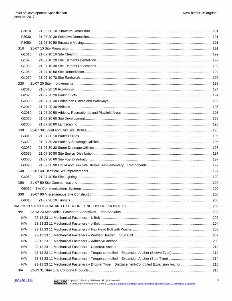
F3010 21-06 30 10 Structure Demolition ................................................................................................................................ 191
F3030 21-06 30 30 Selective Demolition ................................................................................................................................. 191
F3050 21-06 30 50 Structure Moving ...................................................................................................................................... 191
G10 21-07 10 Site Preparation ..................................................................................................................................................... 191
G1010 21-07 10 10 Site Clearing ............................................................................................................................................. 192
G1020 21-07 10 20 Site Elements Demolition ......................................................................................................................... 192
G1030 21-07 10 30 Site Element Relocations ......................................................................................................................... 192
G1050 21-07 10 50 Site Remediation ...................................................................................................................................... 192
G1070 21-07 10 70 Site Earthwork .......................................................................................................................................... 192
G20 21-07 20 Site Improvements ................................................................................................................................................. 193
G2010 21-07 20 10 Roadways ................................................................................................................................................ 194
G2020 21-07 20 20 Parking Lots ............................................................................................................................................. 194
G2030 21-07 20 30 Pedestrian Plazas and Walkways ............................................................................................................ 195
G2040 21-07 20 40 Airfields .................................................................................................................................................... 195
G2050 21-07 20 50 Athletic, Recreational, and Playfield Areas .............................................................................................. 195
G2060 21-07 20 60 Site Development ..................................................................................................................................... 195
G2080 21-07 20 80 Landscaping ............................................................................................................................................. 195
G30 21-07 30 Liquid and Gas Site Utilities ................................................................................................................................... 195
G3010 21-07 30 10 Water Utilities ........................................................................................................................................... 196
G3020 21-07 30 20 Sanitary Sewerage Utilities ...................................................................................................................... 196
G3030 21-07 30 30 Storm Drainage Utilities ........................................................................................................................... 197
G3050 21-07 30 50 Site Energy Distribution ............................................................................................................................ 197
G3060 21-07 30 60 Site Fuel Distribution ................................................................................................................................ 197
G3090 21-07 30 90 Liquid and Gas Site Utilities Supplementary Components .................................................................... 197
G40 21-07 40 Electrical Site Improvements ................................................................................................................................. 197
G4050 21-07 40 50 Site Lighting ............................................................................................................................................. 199
G50 21-07 50 Site Communications ............................................................................................................................................. 199
G5010 – Site Communications Systems ........................................................................................................................................ 200
G90 21-07 90 Miscellaneous Site Construction ............................................................................................................................ 200
G9010 21-07 90 10 Tunnels .................................................................................................................................................... 200
N/A 23-13 STRUCTURAL AND EXTERIOR ENCLOSURE PRODUCTS .......................................................................................... 202
N/A 23-13-23 Mechanical Fasteners, Adhesives, and Sealants ............................................................................................... 202
N/A 23-13 23 11 Mechanical Fasteners – L-Bolt ..................................................................................................................... 202
N/A 23-13 23 11 Mechanical Fasteners – J-Bolt ..................................................................................................................... 204
N/A 23-13 23 11 Mechanical Fasteners – Hex Head Bolt with Washer ................................................................................... 205
N/A 23-13 23 11 Mechanical Fasteners – Welded Headed Stud Bolt .................................................................................. 207
N/A 23-13 23 11 Mechanical Fasteners – Adhesive Anchor ................................................................................................... 208
N/A 23-13 23 11 Mechanical Fasteners – Undercut Anchor .................................................................................................... 210
N/A 23-13 23 11 Mechanical Fasteners – Torque-controlled Expansion Anchor (Sleeve Type) .......................................... 212
N/A 23-13 23 11 Mechanical Fasteners – Torque-controlled Expansion Anchor (Stud Type) .............................................. 214
N/A 23-13 23 11 Mechanical Fasteners – Drop-in Type Displacement-Controlled Expansion Anchor ................................. 216
N/A 23-13 31 Structural Concrete Products ................................................................................................................................. 218
Level of Development Specification Version: 2017
www.bimforum.org/lod
Back to TOC Copyright © 2017 by BIMForum. All rights reserved 9
This document is copyrighted under a Creative Commons Attribution-NonCommercial-NoDerivatives 4.0 International License.
N/A 23-13 31 17 Formwork– Concrete Column ....................................................................................................................... 218
N/A 23-13 31 17 Formwork– Concrete Slab ............................................................................................................................ 220
CIVIL ...................................................................................................................................................................................................... 222
Highway Bridges Precast Structural I Girder (Concrete) .................................................................................................................... 222
Highway Bridge Girder Steel .............................................................................................................................................................. 225
Railroad Bridges Precast Structural I Girder (Concrete) ..................................................................................................................... 226
Railroad Bridge Girder Steel ............................................................................................................................................................... 228

Level of Development Specification Version: 2017
www.bimforum.org/lod
Back to TOC Copyright © 2017 by BIMForum. All rights reserved 10
This document is copyrighted under a Creative Commons Attribution-NonCommercial-NoDerivatives 4.0 International License.
CHANGES FROM 2016 VERSION
Note – Changes in the Element Geometry section are indicated with a change bar in the left margin. Items such as
grammar corrections, added Uniformat descriptions, added Masterformat references, added or upgraded graphics, minor
corrections/additions, etc. are marked with a bar but not detailed in this section.
General notes
Non-Graphic Information
All calls for non-graphic information have been deleted from Part I and addressed in Part II
“No-fly zones”
Where zones that are not to be penetrated by other elements are required by code, operational, or structural considerations (door
swings, electrical panel access clearance, foundation element areas or bearing influence, etc.), an item has been added to LOD 300
definitions calling for the zones to be either modeled to facilitate clash detection or accommodated by model-checking software.
Opening Elements (doors, windows, etc.)
Existing LOD 350 calls for modeling of rough opening deleted, moved to definitions of walls, floors, and roofs.
Openings and Penetrations and Similar Elements
LOD 300 definitions have been adjusted to call for major openings such as windows, doors, and large mechanical elements to be
modeled to nominal dimensions.
LOD 350 definitions have been adjusted to call for all penetrations to be modeled to rough opening dimensions.
Where elements such as MEP distribution components penetrate other elements such as walls, the existing LOD 350 calls for modeling
of the penetration element itself (e.g. a sleeve) have been clarified.
Specific Changes
Introduction The Introduction has been removed and provided in a separate document – LOD Spec 2017 Guide. This Document also includes white papers on use of the spec.
Executive Summary
Added
Fundamental LOD Definitions – LOD 300
Call for element location added
Uniformat Omniclass
N/A 36-51 73 11 13 11 19 Spaces – Added
N/A 36-51 73 11 13 17 11 Horizontal Grids – Added
N/A 36-51 73 11 13 17 13 Vertical Levels - Added
A10 21-01 10 Foundations – LOD 200. Provision for location added
A1020.10.10 21-01 10 20 20 Helical Piles and Piers – Added
A4010 21-01 40 10 Standard Slabs-on-Grade
• LOD 300. Provision for openings added
• LOD 400. Provision for fully modeled rebar added

Level of Development Specification Version: 2017
www.bimforum.org/lod
Back to TOC Copyright © 2017 by BIMForum. All rights reserved 11
This document is copyrighted under a Creative Commons Attribution-NonCommercial-NoDerivatives 4.0 International License.
B1020 21-02 10 20 Roof Construction – logic clarification added:
• If modeling roof as a single composite element including structure use B1020
• If modeling individual layers as separate elements use: o B1020.10 Roof Structural Frame o B1020.20 Roof Decks, Slabs, and Sheathing
B1020.20 21-02 10 20 20 Roof Decks, Slabs, and Sheathing – Detail added
B1080.70 21-02 10 80 70 Metal Walkways – Detail added
B2010 21-02 20 10 Exterior Walls – logic clarification added:
• If modeling wall as a single composite element use B2010
• If modeling individual layers as separate elements use: o B2010.10 Exterior Wall Veneer o B2010.20 Exterior Wall Construction o B2010.30 Exterior Wall Interior Skin
B2010 21-02 20 10 Exterior Walls – LOD 350. Requirement for hosted objects to be at LOD 350 deleted.
B2010.20.10 21-02 20 10 10 Exterior Wall Construction (Wood) – Previously B2010
B2010.20.20 21-02 20 10 20 Exterior Wall Construction (Cold-Form Metal Framoing) – Previously B2010
B2010.20.30 21-02 20 10 20 30 Exterior Wall Construction (Masonry) – Previously B2010
B2010.20.40 21-02 20 10 20 40 Exterior Wall Construction (Concrete) – Previously B2010
B2010.30 21-02 20 10 30 Exterior Wall Interior Skin
• LOD 100 – Changed to N/A
• LOD 200 – Detail added
• LOD 300 – Detail added
B2020.30 21-02 20 20 30 Exterior Window Wall – LOD 300. “Structural support systems of wall to be modeled” deleted – addressed in wall element definitions
B3010 21-02 30 10 Roofing – Detail added
D1010.10 21-04 10 10 10 Elevators – Added detail
G1070.10 21-07 10 70 10 Grading – Added
N/A 23-13 23 11 Mechanical Fasteners – Added
N/A 23-13 31 17 Formwork - Added

Level of Development Specification Version: 2017
www.bimforum.org/lod
Back to TOC Copyright © 2017 by BIMForum. All rights reserved 12
This document is copyrighted under a Creative Commons Attribution-NonCommercial-NoDerivatives 4.0 International License.
UPDATES OF THIS DOCUMENT While this document is intended as a reference that can be cited in agreements such as contracts and BIM execution plans, it is recognized that the use of BIM in design and construction is evolving. To accommodate this evolution this document will be updated periodically in clearly identifiable versions. A project can adopt a specific version and then has the option to remain with that version or update if a new version is published. Initially the target update frequency is annually, but that may change in the future. In addition, interim updates may be issued if needed.
Revision History 11/07/17 Level of Development Specification 2017
08/25/17 Level of Development Specification 2017
DRAFT FOR PUBLIC COMMENT
10/17/16 Level of Development Specification 2016
08/25/16 Level of Development Specification 2016
DRAFT FOR PUBLIC COMMENT
Definitions have not been changed except for minor grammatical corrections and formatting. Engineered metal building structures, precast concrete, highway and rail road bridge content moved from Appendix to main body.
10/30/15 Level of Development Specification 2015 Definitions have not been changed except for minor grammatical corrections and formatting. New content released as an Appendix to Part A for engineered metal building structures, precast concrete, highway bridge content and rail road bridge content.
4/30/15 Level of Development Specification 2015
DRAFT FOR PUBLIC COMMENT
Definitions have not been changed except for minor grammatical corrections and formatting. Part B, Model Element Table, and Attribute Tables were added.
12/30/14 Level of Development Specification 2014 Definitions have not been changed except for minor grammatical corrections and formatting. Images and image
notes have been added in blue italics font.
8/22/13 Level of Development Specification 2013
4/24/13 Initial draft for public review
Revision Process
Public Comment
Each new version is first released as a draft for public comment. Feedback is evaluated and resolved prior to the publishing of the official version.
Appendix
An increasing number of professional organizations are adopting this Specification and providing additional content relating to their domains. To accommodate information that becomes available after the public-comment release but prior to the final release, content is developed in collaboration with industry organizations and leading expert practitioners, and then vetted by the LOD working group. This content is released as an Appendix to Part A and as additional identified Attribute Table tabs in Part B. The new content is then integrated into the next public comment draft.

Level of Development Specification Version: 2017
www.bimforum.org/lod
Back to TOC Copyright © 2017 by BIMForum. All rights reserved 13
This document is copyrighted under a Creative Commons Attribution-NonCommercial-NoDerivatives 4.0 International License.
FUNDAMENTAL LOD DEFINITIONS3
LOD 100
The Model Element may be graphically represented in the Model with a symbol or other generic representation, but does not satisfy the requirements for LOD 200. Information related to the Model Element (i.e. cost per square foot, tonnage of HVAC, etc.) can be derived from other Model Elements.
BIMForum Interpretation: LOD 100 elements are not geometric representations. Examples are information attached to other model elements or symbols showing the existence of a component but not its shape, size, or precise location. Any information derived from LOD 100 elements must be considered approximate.
LOD 200
The Model Element is graphically represented within the Model as a generic system, object, or assembly with approximate quantities, size, shape, location, and orientation. Non-graphic information may also be attached to the Model Element.
BIMForum interpretation: At this LOD elements are generic placeholders. They may be recognizable as the components they represent, or they may be volumes for space reservation. Any information derived from LOD 200 elements must be considered approximate.
LOD 300
The Model Element is graphically represented within the Model as a specific system, object or assembly in terms of quantity, size, shape, location, and orientation. Non-graphic information may also be attached to the Model Element.
BIMForum interpretation: The quantity, size, shape, location, and orientation of the element as designed can be measured directly from the model without referring to non-modeled information such as notes or dimension call-outs. The project origin is defined and the element is located accurately with respect to the project origin.
LOD 350
The Model Element is graphically represented within the Model as a specific system, object, or assembly in terms of quantity, size, shape, location, orientation, and interfaces with other building systems. Non-graphic information may also be attached to the Model Element.
BIMForum interpretation. Parts necessary for coordination of the element with nearby or attached elements are modeled. These parts will include such items as supports and connections. The quantity, size, shape, location, and orientation of the element as designed can be measured directly from the model without referring to non-modeled information such as notes or dimension call-outs.
LOD 400
The Model Element is graphically represented within the Model as a specific system, object or assembly in terms of size, shape, location, quantity, and orientation with detailing, fabrication, assembly, and installation information. Non-graphic information may also be attached to the Model Element.
BIMForum interpretation. An LOD 400 element is modeled at sufficient detail and accuracy for fabrication of the represented component. The quantity, size, shape, location, and orientation of the element as designed can be measured directly from the model without referring to non-modeled information such as notes or dimension call-outs.
3 The definitions for LOD 100, 200, 300, 400, and 500 included in this Specification represent the updated language that appears in the AIA’s most recent BIM
protocol document, G202–2013, Building Information Modeling Protocol Form. The LOD 100, 200, 300, 400 and 500 definitions are produced by the AIA and have been used by permission. Copyright © 2013. The American Institute of Architects. All rights reserved. LOD 350 was developed by the BIMForum working group. Copyright © 2013. The BIMForum and the American Institute of Architects. All rights reserved.
Level of Development Specification Version: 2017
www.bimforum.org/lod
Back to TOC Copyright © 2017 by BIMForum. All rights reserved 14
This document is copyrighted under a Creative Commons Attribution-NonCommercial-NoDerivatives 4.0 International License.
LOD 500
The Model Element is a field verified representation in terms of size, shape, location, quantity, and orientation. Non-graphic information may also be attached to the Model Elements.
BIMForum interpretation. Since LOD 500 relates to field verification and is not an indication of progression to a higher level of model element geometry or non-graphic information, this Specification does not define or illustrate it.
Example – Light Fixture: 1) 100 cost/sf attached to floor slabs 2) 200 light fixture, generic/approximate size/shape/location 3) 300 Design specified 2x4 troffer, specific size/shape/location 4) 350 Actual model, Lightolier DPA2G12LS232, specific size/shape/location 5) 400 As 350, plus special mounting details, as in a decorative soffit

Level of Development Specification Version: 2017
www.bimforum.org/lod
Uniformat Omniclass
Back to TOC Copyright © 2017 by BIMForum. All rights reserved 15
This document is copyrighted under a Creative Commons Attribution-NonCommercial-NoDerivatives 4.0 International License.
PART I – ELEMENT GEOMETRY
N/A 36-51 OFFICE RESOURCES
N/A 36-51 73 11 13 11 19 SPACES Associated Masterformat Sections: N/A
100 Spaces are modeled as generic objects with approximate size, shape and location. This level is typically appropriate for design of spatial requirements where space objects are placed in a model either in a random manner for quantification or in a ‘blocking and stacking’ process.
Bounding elements are not required, but may be needed if specific dimensions are desired.
Element modeling to include:
• Space object based on area required by program or brief.
•
From http://revitaddons.blogspot.com/2014/02/free-space-planning-massing-from-excel.html
200 Spaces are modeled or placed with bounding elements such as walls and columns that are at a minimum of LOD200. Perimeter and area of spaces are calculated with respect to the bounding elements.
LOD of spaces shall not exceed the LOD of the bounding elements. For example, if interior partitions are defined at LOD200, the space objects for the project cannot be delivered at LOD300.
Element modeling to include:
• Vertical bounding elements at LOD200
• Space objects that automatically associate with vertical bounding elements
From http://cad-3d.blogspot.com/2012/06/improve-usage-of-bim-during-early.html
300 Spaces are modeled or placed with bounding elements that are at a minimum of LOD300. Perimeter and area of spaces are calculated with respect to the bounding elements.
Element modeling to include:

Level of Development Specification Version: 2017
www.bimforum.org/lod
Uniformat Omniclass
Back to TOC Copyright © 2017 by BIMForum. All rights reserved 16
This document is copyrighted under a Creative Commons Attribution-NonCommercial-NoDerivatives 4.0 International License.
1) Vertical bounding elements at LOD300 2) Space objects that automatically associate with vertical
bounding elements
350 Comply with the LOD300 requirements.
Volume of the space is accurately calculated to the nearest horizontal finish surface such as a ceiling or underside of slab above.
Element modeling to include:
1) Vertical bounding elements to minimum LOD300 2) Horizontal bounding elements such as ceilings or slabs 3) Space objects that automatically associate with vertical
and horizontal bounding elements
N/A 36-51 73 11 13 17 11 Horizontal Grids N/A 36-51 73 11 13 17 13 Vertical Levels Includes: Grids and elevations used to coordinate and annotate models.
100
200 Grids & Elevations
Equipment, Building, Campus, Civil, and GIS is approximate in its relation to the content in the given model.
LOD 200 Grids & Elevations

Level of Development Specification Version: 2017
www.bimforum.org/lod
Uniformat Omniclass
Back to TOC Copyright © 2017 by BIMForum. All rights reserved 17
This document is copyrighted under a Creative Commons Attribution-NonCommercial-NoDerivatives 4.0 International License.
300 Grids & Elevations
Equipment, Building, Campus, Civil, and GIS is specific in its relation to the content in the given model.
LOD 300 Grids & Elevations

Level of Development Specification Version: 2017
www.bimforum.org/lod
Uniformat Omniclass
Back to TOC Copyright © 2017 by BIMForum. All rights reserved 18
This document is copyrighted under a Creative Commons Attribution-NonCommercial-NoDerivatives 4.0 International License.
A 21-01 SUBSTRUCTURE Associated Masterformat Sections: 01 82 00
A10 21-01 10 Foundations Associated Masterformat Sections: 01 82 13
100 Assumptions for foundations are included in other modeled elements such as an architectural floor element or volumetric mass that contains layer for assumed structural framing depth.
Or, schematic elements that are not distinguishable by type or material. Assembly depth/thickness and locations still flexible.
200 Element modeling to include:
• Approximate size and shape of foundation element
• Structural building grids for local project coordinate system are defined in model and approximately coordinated with civil coordinate .
A1010 21-01 10 10 Standard Foundations Includes: Formwork, concrete, masonry and reinforcement. Includes Standard Foundation Supplementary Components as appropriate. May Include: Related Activities: Excavation, dewatering, excavation support systems, backfill and compaction, and soil treatment.
Note – for formwork see Structural Concrete Products
Associated Masterformat Sections: 01 82 13
100 See A10
200 See A10
300 Elements are modeled to the design-specified size and shape of the foundation.
Element modeling to include:
• Overall size and geometry of the foundation element
• Sloping surfaces or floor depressions
• External dimensions of the members
• Main openings such as elevators and other shafts

Level of Development Specification Version: 2017
www.bimforum.org/lod
Uniformat Omniclass
Back to TOC Copyright © 2017 by BIMForum. All rights reserved 19
This document is copyrighted under a Creative Commons Attribution-NonCommercial-NoDerivatives 4.0 International License.
A1010.10 21-01 10 10 10 Wall Foundations (Shallow Foundations) Associated Masterformat Sections: 03 30 00 / 03 40 00 / 04 20 00 / 06 14 00
100 See A10
200 See A10
Image Notes:
• Generic wall foundation is modeled.
• Site is generically modeled from geotechnical
information in geotechnical report.
300 Element modeling to include:
1) Overall size and geometry of the foundation element 2) Sloping surfaces. 3) External dimensions of the members 4) Geotechnical bearing strata elevation is modeled from
geotechnical report. 5) Area of bearing influence – modeled or
accommodated by model checking software
Image Notes:
6) Wall foundation sizes are accurately modeled with
footings where applicable.
7) Bearing elevation is modeled from the geotechnical
report.
8) Geotechnical regions are shown for context and not
required to be modeled as part of this element at this
LOD.
9) See slab on grade for related conditions at this LOD.
2 A1010.10-LOD-300 Wall Foundation
4
2
1
3
1 A1010.10-LOD-200 Wall Foundation
Level of Development Specification Version: 2017
www.bimforum.org/lod
Uniformat Omniclass
Back to TOC Copyright © 2017 by BIMForum. All rights reserved 20
This document is copyrighted under a Creative Commons Attribution-NonCommercial-NoDerivatives 4.0 International License.
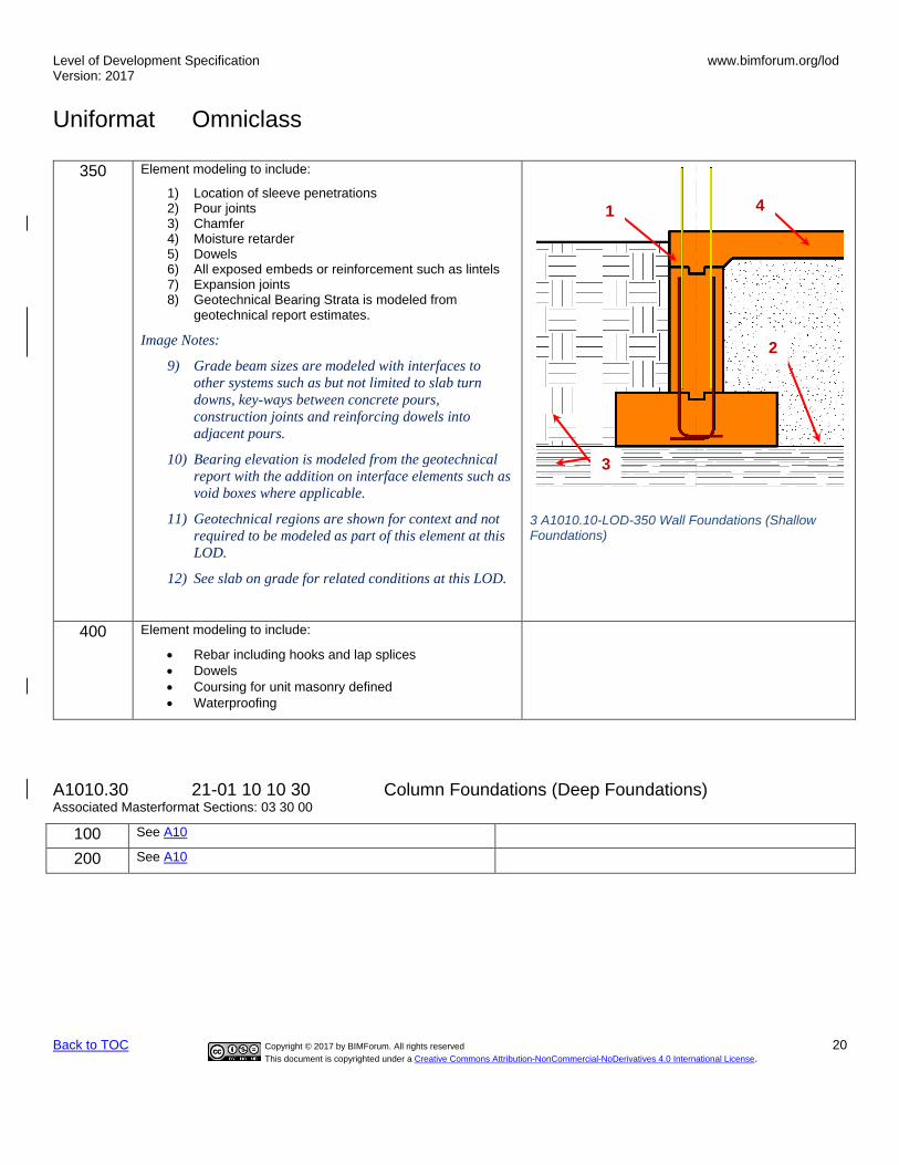
350 Element modeling to include:
1) Location of sleeve penetrations 2) Pour joints 3) Chamfer 4) Moisture retarder 5) Dowels 6) All exposed embeds or reinforcement such as lintels 7) Expansion joints 8) Geotechnical Bearing Strata is modeled from
geotechnical report estimates.
Image Notes:
9) Grade beam sizes are modeled with interfaces to
other systems such as but not limited to slab turn
downs, key-ways between concrete pours,
construction joints and reinforcing dowels into
adjacent pours.
10) Bearing elevation is modeled from the geotechnical
report with the addition on interface elements such as
void boxes where applicable.
11) Geotechnical regions are shown for context and not
required to be modeled as part of this element at this
LOD.
12) See slab on grade for related conditions at this LOD.
3 A1010.10-LOD-350 Wall Foundations (Shallow Foundations)
400 Element modeling to include:
• Rebar including hooks and lap splices
• Dowels
• Coursing for unit masonry defined
• Waterproofing
A1010.30 21-01 10 10 30 Column Foundations (Deep Foundations) Associated Masterformat Sections: 03 30 00
100 See A10
200 See A10
4
2
1
3

Level of Development Specification Version: 2017
www.bimforum.org/lod
Uniformat Omniclass
Back to TOC Copyright © 2017 by BIMForum. All rights reserved 21
This document is copyrighted under a Creative Commons Attribution-NonCommercial-NoDerivatives 4.0 International License.
300 Element modeling to include:
1) Assumed bearing depth per geotechnical report with designed penetration geometry modeled.
2) Top of Pier 3) Size of Pier 4) Area of bearing influence - modeled or
accommodated by model checking software
Image Notes:
5) Pier sizes are accurately modeled with top of pier
elevation, estimated depth to bearing and
specified depth of penetration into bearing strata.
6) Geotechnical regions are shown for context and
not required to be modeled as part of this element
at this LOD.
1
2
4 A1010.30-LOD-300 Column Foundations (Deep Foundations)

Level of Development Specification Version: 2017
www.bimforum.org/lod
Uniformat Omniclass
Back to TOC Copyright © 2017 by BIMForum. All rights reserved 22
This document is copyrighted under a Creative Commons Attribution-NonCommercial-NoDerivatives 4.0 International License.
350 Element modeling to include:
• Actual Top of Pier (TOP) and expected Bottom of Pier (BOT) modeled per engineer’s review of site conditions
• Foundation dowel locations and anchor rods if applicable.
Image Notes:
• Pier sizes are accurately modeled with interfaces
to other systems such as but not limited to slab
turn downs, key-ways between concrete pours,
construction joints and reinforcing dowels into
adjacent pours.
• Geotechnical regions are shown for context and
not required to be modeled as part of this element
at this LOD.
5 A1010.30-LOD-350 Column Foundations
1
2
Level of Development Specification Version: 2017
www.bimforum.org/lod
Uniformat Omniclass
Back to TOC Copyright © 2017 by BIMForum. All rights reserved 23
This document is copyrighted under a Creative Commons Attribution-NonCommercial-NoDerivatives 4.0 International License.
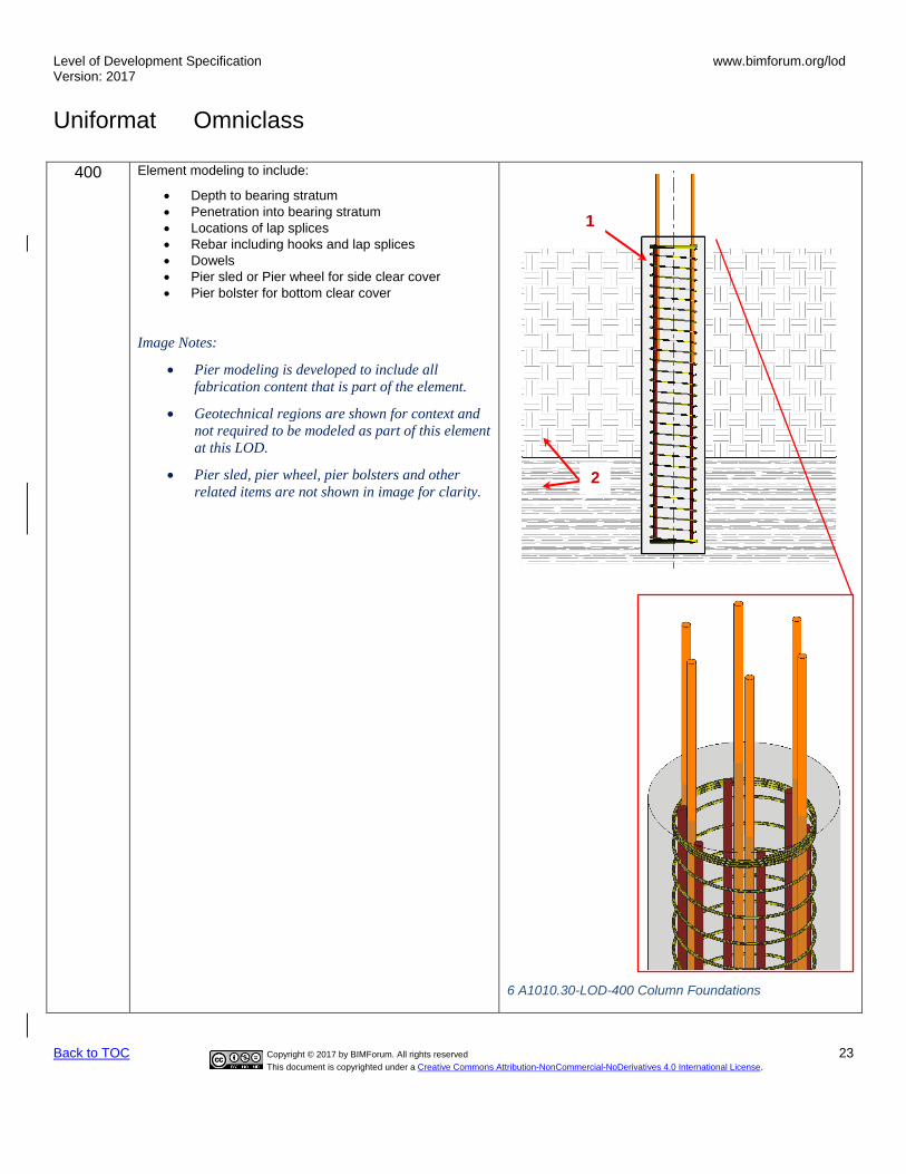
400 Element modeling to include:
• Depth to bearing stratum
• Penetration into bearing stratum
• Locations of lap splices
• Rebar including hooks and lap splices
• Dowels
• Pier sled or Pier wheel for side clear cover
• Pier bolster for bottom clear cover
Image Notes:
• Pier modeling is developed to include all
fabrication content that is part of the element.
• Geotechnical regions are shown for context and
not required to be modeled as part of this element
at this LOD.
• Pier sled, pier wheel, pier bolsters and other
related items are not shown in image for clarity.
6 A1010.30-LOD-400 Column Foundations
1
2
Level of Development Specification Version: 2017
www.bimforum.org/lod
Uniformat Omniclass
Back to TOC Copyright © 2017 by BIMForum. All rights reserved 24
This document is copyrighted under a Creative Commons Attribution-NonCommercial-NoDerivatives 4.0 International License.
A1010.90 21-01 10 10 90 Standard Foundation Supplementary Components TBD
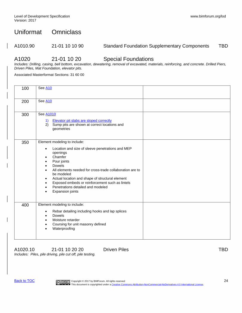
A1020 21-01 10 20 Special Foundations Includes: Drilling, casing, bell bottom, excavation, dewatering, removal of excavated, materials, reinforcing, and concrete. Drilled Piers, Driven Piles, Mat Foundation, elevator pits.
Associated Masterformat Sections: 31 60 00
100 See A10
200 See A10
300 See A1010
1) Elevator pit slabs are sloped correctly 2) Sump pits are shown at correct locations and
geometries
350 Element modeling to include:
• Location and size of sleeve penetrations and MEP openings
• Chamfer
• Pour joints
• Dowels
• All elements needed for cross-trade collaboration are to be modeled
• Actual location and shape of structural element
• Exposed embeds or reinforcement such as lintels
• Penetrations detailed and modeled
• Expansion joints
400 Element modeling to include:
• Rebar detailing including hooks and lap splices
• Dowels
• Moisture retarder
• Coursing for unit masonry defined
• Waterproofing
A1020.10 21-01 10 20 20 Driven Piles TBD Includes: Piles, pile driving, pile cut off, pile testing.

Level of Development Specification Version: 2017
www.bimforum.org/lod
Uniformat Omniclass
Back to TOC Copyright © 2017 by BIMForum. All rights reserved 25
This document is copyrighted under a Creative Commons Attribution-NonCommercial-NoDerivatives 4.0 International License.
A1020.10.10 21-01 10 20 20 Helical Piles, Helical Piers Associated Masterformat Sections: N/A
100 See A10
200 See A10
Helical Pile
A1020.10.10 LOD 200 Helical Piers
300 Element modeling to include:
• Pile system type
• Pile material
• Coating
• Influence area modeled or accommodated by model checking software
A1020.10.10 LOD 300 Helical Piers

Level of Development Specification Version: 2017
www.bimforum.org/lod
Uniformat Omniclass
Back to TOC Copyright © 2017 by BIMForum. All rights reserved 26
This document is copyrighted under a Creative Commons Attribution-NonCommercial-NoDerivatives 4.0 International License.
350 Element modeling to include:
• Spacing
• Plate Size
• Bearing Strata
A1020.10.10 LOD 350 Helical Piers
400 Element modeling to include:
• Full fabrication connections
A1020.10.10 LOD 400 Helical Piers
A1020.20 21-01 10 20 20 Caissons TBD
A1020.30 21-01 10 20 30 Special Foundation Walls TBD
A1020.40 21-01 10 20 40 Foundation Anchors TBD
A1020.50 21-01 10 20 50 Underpinning TBD

Level of Development Specification Version: 2017
www.bimforum.org/lod
Uniformat Omniclass
Back to TOC Copyright © 2017 by BIMForum. All rights reserved 27
This document is copyrighted under a Creative Commons Attribution-NonCommercial-NoDerivatives 4.0 International License.
A1020.60 21-01 10 20 60 Raft Foundations TBD
A1020.70 21-01 10 20 70 Pile Caps TBD
A1020.80 21-01 10 20 80 Grade Beams Includes: Formwork, reinforcement, and concrete.
Associated Masterformat Sections: 03 30 00
100 See A10
200 See A10
Image Notes:
• Generic beam geometry is shown.
• Geotechnical regions are shown for context and not
required to be modeled as part of this element at this
LOD.
7 A1020.80-LOD-200 Grade Beams
300 See A1010
Image Notes:
1) Grade Beam
2) See slab on grade (A4010, A4020) for related
conditions at this LOD.
1) Geotechnical regions are shown for context and not
required to be modeled as part of this element at this
LOD.
8 A1020.80-LOD-300 Grade Beams
2
1
2
3

Level of Development Specification Version: 2017
www.bimforum.org/lod
Uniformat Omniclass
Back to TOC Copyright © 2017 by BIMForum. All rights reserved 28
This document is copyrighted under a Creative Commons Attribution-NonCommercial-NoDerivatives 4.0 International License.
350 Element modeling to include:
• Water stops
• Pour joints and sequences required to identify reinforcing lap spice, scheduling, etc.
• Chamfer
Image Notes:
• Grade beam sizes are modeled with interfaces to
other systems such as but not limited to slab turn
downs, key-ways between concrete pours,
construction joints and reinforcing dowels into
adjacent pours.
• Interface elements such as void boxes or critical
bearing zones are modeled where applicable.
• See slab on grade ((A4010, A4020) for related
conditions at this LOD.
• Geotechnical regions are shown for context and not
required to be modeled as part of this element at this
LOD.
9 A1020.80-LOD-350 Grade Beams
400 Element modeling to include:
• Detailed post-tensioned components
• Rebar including hooks and lap splices
• Dowels
• Waterproofing
A20 21-01 20 Subgrade Enclosures Associated Masterformat Sections: 01 82 16
100 Solid mass model representing overall building volume; or, schematic wall elements that are not distinguishable by type or material.
Assembly depth/thickness and locations still flexible.
200 Element modeling to include:
• Approximate size and shape of the subgrade enclosure element.
• Structural building grids for local project coordinate system are defined in model and coordinated with global civil coordinate system (State Plane Coordinate System, etc).
Suggested Baseline Attributes
1) Member Type
2
1 3
4

Level of Development Specification Version: 2017
www.bimforum.org/lod
Uniformat Omniclass
Back to TOC Copyright © 2017 by BIMForum. All rights reserved 29
This document is copyrighted under a Creative Commons Attribution-NonCommercial-NoDerivatives 4.0 International License.
A2010 21-01 20 10 Walls for Subgrade Enclosures Includes: Perimeter walls enclosing building space below grade. Includes formwork, reinforcing, concrete and masonry. Includes Subgrade Enclosure Wall Supplementary Components as appropriate. May Include: Related Activities: Excavation, dewatering, excavation support systems, backfill and compaction, and soil treatment.
Associated Masterformat Sections: 01 82 16
100 See A20
200 See A20
300 Element modeling to include:
• Overall size and geometry of the subgrade element
• Sloping surfaces
• External dimensions of the element
• Major openings such as large mechanical elements modeled to nominal dimensions.
350 Element modeling to include:
• Chamfers
• All penetrations modeled to rough opening dimensions.
• Pour joints
• Rebar and any embedded elements modeled at congested areas where specified by project BXP which is typically with in a set distance from the area of congestion.
• Any permanent shoring or forming structures such as void boxes
• insulation
• Expansion joints
• Moisture retarder
• Exposed embeds or reinforcement such as lintels
• Penetrations detailed and modeled
• Expansion joints
400 Element modeling to include:
• Rebar including hooks and lap splices
• Dowels
• Coursing for unit masonry defined
• Waterproofing
A2010.10 21-01 20 10 10 Subgrade Enclosure Wall Construction TBD
A2010.20 21-01 20 10 20 Subgrade Enclosure Wall Interior Skin TBD
A2010.90 21-01 20 10 90 Subgrade Enclosure Wall Supplementary Components TBD

Level of Development Specification Version: 2017
www.bimforum.org/lod
Uniformat Omniclass
Back to TOC Copyright © 2017 by BIMForum. All rights reserved 30
This document is copyrighted under a Creative Commons Attribution-NonCommercial-NoDerivatives 4.0 International License.
A40 21-01 40 Slabs-on-Grade Associated Masterformat Sections: 01 82 00
100 Assumptions for slabs are included in other modeled elements such as a volumetric mass or architectural floor element that contains a layer for assumed structural framing depth.
200 Element modeling to include
• Generic slab with approximate thickness.
• Structural building grids for local project coordinate system are defined in model and coordinated with global civil coordinate system (State Plane Coordinate System, etc.)
10 A40-LOD-200 Slabs-on-Grade
A4010 21-01 40 10 Standard Slabs-on-Grade Includes: Slab construction supported continuously by earth or compacted fill. Includes fine grading, subbase layer, mud slab, insulation, vapor retarder, waterproofing, formwork, expansion joints, control joints, reinforcement, concrete, and finishing includes: Slabs-On-Grade Supplementary Components as appropriate. May Include: Related Activities: Excavation, dewatering, excavation support systems, backfill and compaction, and soil treatment.
Associated Masterformat Sections: 03 30 00
100 See A40
200 See A40
300 Element modeling to include:
• Overall size, thickness and geometry of the slab
• Major openings such as large mechanical elements modeled to nominal dimensions.
• Slab depressions
• Edge turn downs
• Material strength
• Surfaces modeled to actual slopes
11 A4010-LOD-300 Standard Slabs-on-Grade

Level of Development Specification Version: 2017
www.bimforum.org/lod
Uniformat Omniclass
Back to TOC Copyright © 2017 by BIMForum. All rights reserved 31
This document is copyrighted under a Creative Commons Attribution-NonCommercial-NoDerivatives 4.0 International License.
350 Element modeling to include:
• All penetrations modeled to rough opening dimensions.
• Pour joints
• Control joints
• Expansion joints
• Water stops
• Rebar and any embedded elements modeled at congested areas where specified by project BIMXP which is typically with in a set distance from the area of congestion.
• Void boxes
• Anchor rods
• Dowels
• Post-tension profile and strands if required by the BXP.
400 Element modeling to include:
• Fully modeled rebar
• Actual slab dimensions and profiles with fully modeled rebar
• Post tensioning components
• All joints
• Water proofing
• Finish
A4020 21-01 40 20 Structural Slabs-on-Grade
Includes: Self-supporting slab construction not supported continuously by earth or compacted fill. Includes formwork, accessories, reinforcement, concrete, and finishing. Includes Slabs-On-Grade Supplementary Components as appropriate. May Include: Related Activities: Excavation, dewatering, excavation support systems, backfill and compaction, and soil treatment.
Associated Masterformat Sections: 03 30 00
100 See A40
200 See A40
12 A4010-LOD-350 Standard Slabs-on-Grade

Level of Development Specification Version: 2017
www.bimforum.org/lod
Uniformat Omniclass
Back to TOC Copyright © 2017 by BIMForum. All rights reserved 32
This document is copyrighted under a Creative Commons Attribution-NonCommercial-NoDerivatives 4.0 International License.
300 Element modeling to include:
• Overall size, thickness and geometry of the slab-on-grade
• Major openings such as large mechanical elements modeled to nominal dimensions.
• Slab depressions
• Edge turn downs
• All sloping surfaces included in model element with exception of elements affected by manufacturer selection which are not known at this LOD. Such conditions could include floor geometry differences where different specified manufacturers will not be known until the actual system is selected.
350 Element modeling to include:
• All penetrations modeled to rough opening dimensions.
• Pour joints
• Control joints
• Expansion joints
• Water Stops
• Rebar and any embedded elements modeled at congested areas where specified by project BXP which is typically with in a set distance from the area of congestion.
• Void boxes
• Anchor rods
• Moisture retarder
• Dowels
• Post-tension profile and strands modeled if required by the BXP
400 Element modeling to include:
• Fully modeled rebar
• Actual slab dimensions and profiles with fully modeled rebar
• Post tensioning components
• All joints
• Water proofing
• Finish
A4030 21-01-40-30 Slab Trenches TBD
A4040 21-01-40-40 Pits and Bases TBD
A4090 21-01-40-90 Slab-On-Grade Supplementary Components TBD
13 A4020-LOD-300 Structural Slabs-on-Grade
14 A4020-LOD-350 Structural Slabs-on-Grade

Level of Development Specification Version: 2017
www.bimforum.org/lod
Uniformat Omniclass
Back to TOC Copyright © 2017 by BIMForum. All rights reserved 33
This document is copyrighted under a Creative Commons Attribution-NonCommercial-NoDerivatives 4.0 International License.
A60 21-01-60 Water and Gas Mitigation TBD
A6010 21-01-60-10 Building Subdrainage TBD
A6020 21-01-60-20 Off-Gassing Mitigation TBD
A90 21-01-90 Substructure Related Activities TBD
A9010 21-01-90-10 Substructure Excavation TBD
A9020 21-01-90-20 Construction Dewatering TBD
A9030 21-01-90-30 Excavation Support TBD
A9040 21-01-90-40 Soil Treatment TBD

Level of Development Specification Version: 2017
www.bimforum.org/lod
Uniformat Omniclass
Back to TOC Copyright © 2017 by BIMForum. All rights reserved 34
This document is copyrighted under a Creative Commons Attribution-NonCommercial-NoDerivatives 4.0 International License.
B 21-02 00 00 SHELL Associated Masterformat Sections: 01 83 00
B10 21-02 10 Superstructure Associated Masterformat Sections: 01 83 13
100 Assumptions for structural framing are included in other modeled elements such as an architectural floor element that contains a layer for assumed structural framing depth or schematic structural elements that are not distinguishable by type or material.
Assembly depth/thickness or component size and locations still flexible.
B1010 21-02 10 10 Floor Construction Associated Masterformat Sections: 01 83 13
100 See B10
200 Model elements to include:
• Floor with approximate dimensions
• Approximate supporting framing members
• Structural grids defined accurately
B1010.10 21-02 10 10 10 Floor Structural Frame Includes: Structural elements required for support of floor construction within basements and above grade. Includes columns, girders, beams, trusses, joists. Includes cast-in-place concrete, precast concrete, unit masonry, metal framed, and wood framed systems. Includes framed and sleeved openings for services. Includes Floor Construction Supplementary Components as appropriate.
Specific structural systems within this section are listed as follows:
• Concrete B1010.10.10
• Precast Structural Inverted T Beam B1010.10.11
• Precast Structural Column B1010.10.12
• Masonry B1010.10.20
• Steel Framing Columns B1010.10.30
• Steel Framing Beams B1010.10.40
• Steel Framing Bracing Rods B1010.10.50
• Steel Joists B1010.10.60
• Cold-Formed Metal Framing B1010.10.70
• Wood Floor Trusses B1010.10.80
Associated Masterformat Sections: 03 30 00 / 03 40 00 / 04 20 00 / 05 10 00 / 05 20 00 05 21 23 / 05 42 00 / 05 44 00 / 06 11 00 / 06 13 00 / 06 13 26 / 06 17 33 / 06 17 36 06 17 53 / 06 18 13 / 06 18 16 / 06 50 00
B1010.10.10 21-02 10 10 10 10 Floor Structural Frame (Concrete)
Associated Masterformat Sections: 03 30 00 / 03 40 00

Level of Development Specification Version: 2017
www.bimforum.org/lod
Uniformat Omniclass
Back to TOC Copyright © 2017 by BIMForum. All rights reserved 35
This document is copyrighted under a Creative Commons Attribution-NonCommercial-NoDerivatives 4.0 International License.
100 See B10
200 Element modeling to include:
• Type of structural concrete system
• Approximate geometry (e.g. depth) of structural elements
300 Element modeling to include:
1) Composite model assembly by type with overall thickness of structural frame
• Specific sizes and locations of main concrete structural members modeled per defined structural grid with correct orientation
• Concrete defined per spec (strength, air entrainment, aggregate size, etc.)
• All sloping surfaces included in model element with exception of elements affected by manufacturer selection
350 Element modeling to include:
• Reinforcing Post-tension profiles and strand locations
• Reinforcement called out, modeled if required by the BXP, typically only in congested areas
• Pour joints and sequences to help identify reinforcing lap splice locations, scheduling, etc.
• Expansion Joints
• Embeds and anchor rods
• Post-tension profile and strands modeled if required by the BXP
• Penetrations for items such as MEP
• Any permanent forming or shoring components
• Shear reinforcing and stud rails
• Critical structural zones for coordination, including but not limited to zones that cannot be penetrated, cut, or damaged
• Chamfer
400 Element modeling to include:
• All reinforcement including post tension elements detailed and modeled camber, etc.
B1010.10.11 21-02 10 10 10 11 Precast Structural Inverted T Beam (Concrete)
Includes: Structural elements required for support of floor construction within basements and above grade. Includes columns, girders, beams, trusses, joists. Includes cast-in-place concrete, precast concrete, unit masonry, metal framed, and wood framed systems. Includes framed and sleeved openings for services.Includes Floor Construction Supplementary Components as appropriate.
Associated Masterformat Sections: 03 30 00 / 03 40 00 / 04 20 00 / 05 10 00 / 05 20 00 05 21 23 / 05 42 00 / 05 44 00 / 06 11 00 / 06 13 00 / 06 13 26 / 06 17 33 / 06 17 36 06 17 53 / 06 18 13 / 06 18 16 / 06 50 00

Level of Development Specification Version: 2017
www.bimforum.org/lod
Uniformat Omniclass
Back to TOC Copyright © 2017 by BIMForum. All rights reserved 36
This document is copyrighted under a Creative Commons Attribution-NonCommercial-NoDerivatives 4.0 International License.
100 See B10
200 Element modeling to include:
• Type of structural concrete system
• Approximate geometry (e.g. depth) of structural elements
15 B1010.10-LOD 200 Precast Structural Inverted T Beam (Concrete)
300 Element modeling to include:
• Specific sizes and locations of main concrete structural members modeled per defined structural grid with correct orientation
• All sloping surfaces included in model element with exception of elements affected by manufacturer selection
16 B1010.10-LOD 300 Precast Structural Inverted T Beam (Concrete)

Level of Development Specification Version: 2017
www.bimforum.org/lod
Uniformat Omniclass
Back to TOC Copyright © 2017 by BIMForum. All rights reserved 37
This document is copyrighted under a Creative Commons Attribution-NonCommercial-NoDerivatives 4.0 International License.
350 Element modeling to include:
• Reinforcing Post-tension profiles and strand locations
• Reinforcement called out, modeled if required by the BXP, typically only in congested areas
• Chamfer
• Pour joints and sequences to help identify reinforcing lap splice locations, scheduling, etc.
• Lifting devices
• Expansion Joints
• Embeds and anchor rods
• Post-tension profile and strands modeled if required by the BXP
• Penetrations for items such as MEP
• Any permanent forming or shoring components
17 B1010.10-LOD 350 Precast Structural Inverted T Beam (Concrete)
400 Element modeling to include:
• All reinforcement including post tension elements detailed and modeled
• Finishes
18 B1010.10-LOD 400 Precast Structural Inverted T Beam (Concrete)
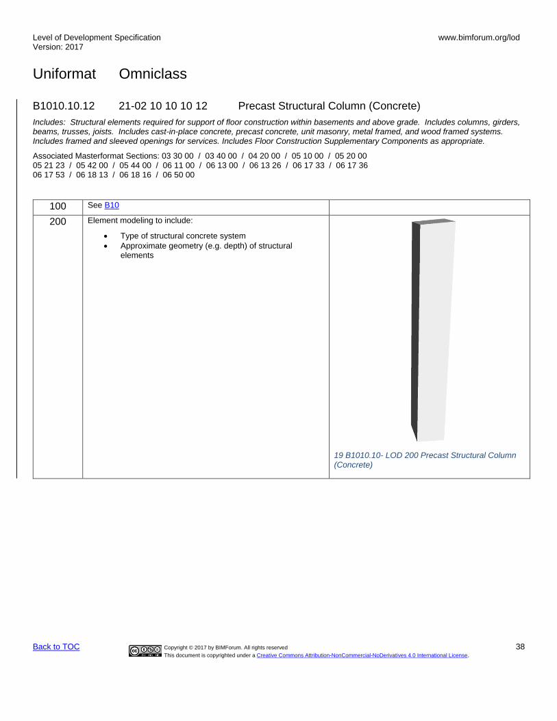
Level of Development Specification Version: 2017
www.bimforum.org/lod
Uniformat Omniclass
Back to TOC Copyright © 2017 by BIMForum. All rights reserved 38
This document is copyrighted under a Creative Commons Attribution-NonCommercial-NoDerivatives 4.0 International License.
B1010.10.12 21-02 10 10 10 12 Precast Structural Column (Concrete)
Includes: Structural elements required for support of floor construction within basements and above grade. Includes columns, girders, beams, trusses, joists. Includes cast-in-place concrete, precast concrete, unit masonry, metal framed, and wood framed systems. Includes framed and sleeved openings for services. Includes Floor Construction Supplementary Components as appropriate.
Associated Masterformat Sections: 03 30 00 / 03 40 00 / 04 20 00 / 05 10 00 / 05 20 00 05 21 23 / 05 42 00 / 05 44 00 / 06 11 00 / 06 13 00 / 06 13 26 / 06 17 33 / 06 17 36 06 17 53 / 06 18 13 / 06 18 16 / 06 50 00
100 See B10
200 Element modeling to include:
• Type of structural concrete system
• Approximate geometry (e.g. depth) of structural elements
19 B1010.10- LOD 200 Precast Structural Column (Concrete)

Level of Development Specification Version: 2017
www.bimforum.org/lod
Uniformat Omniclass
Back to TOC Copyright © 2017 by BIMForum. All rights reserved 39
This document is copyrighted under a Creative Commons Attribution-NonCommercial-NoDerivatives 4.0 International License.
300 Element modeling to include:
• Specific sizes and locations of main concrete structural members modeled per defined structural grid with correct orientation
• All sloping surfaces included in model element with exception of elements affected by manufacturer selection
20 B1010.10 - LOD 300 Precast Structural Column (Concrete)
350 Element modeling to include:
• Reinforcing Post-tension profiles and strand locations
• Reinforcement called out, modeled if required by the BXP, typically only in congested areas
• Chamfer
• Pour joints and sequences to help identify reinforcing lap splice locations, scheduling, etc.
• Expansion Joints
• Lifting devices
• Embeds and anchor rods
• Post-tension profile and strands modeled if required by the BXP
• Penetrations for items such as MEP
• Any permanent forming or shoring components
21 B1010.10 - LOD 350 Precast Structural Column (Concrete)

Level of Development Specification Version: 2017
www.bimforum.org/lod
Uniformat Omniclass
Back to TOC Copyright © 2017 by BIMForum. All rights reserved 40
This document is copyrighted under a Creative Commons Attribution-NonCommercial-NoDerivatives 4.0 International License.
400 Element modeling to include:
• All reinforcement including post tension elements detailed and modeled
• Finishes
22 B1010.10 - LOD 400 Precast Structural Column (Concrete)
B1010.10.20 21-02 10 10 10 20 Floor Structural Frame (Masonry)
Associated Masterformat Sections: 04 20 00
100 See B10
200 Element modeling to include:
• Type of structural masonry system
300 Element modeling to include:
• Specific sizes of main structural elements modeled per defined structural grid with correct dimensions
• Rough openings with reinforcement and lintels called out
• Penetrations for items such as MEP
350 Element modeling to include:
• Actual location and shape of structural masonry element
• All exposed embeds or reinforcement such as lintels
• All penetrations modeled to rough opening dimensions
• Expansion joints
• Grouted cell locations

Level of Development Specification Version: 2017
www.bimforum.org/lod
Uniformat Omniclass
Back to TOC Copyright © 2017 by BIMForum. All rights reserved 41
This document is copyrighted under a Creative Commons Attribution-NonCommercial-NoDerivatives 4.0 International License.
400 Element modeling to include:
• Waterproofing
• Coursing
• Reinforcing Grout
B1010.10.30 21-02 10 10 10 30 Floor Structural Frame (Steel Framing Columns)
Associated Masterformat Sections: 05 10 00
100 Generic column element, See B10.
200 See B1010
300 Element modeling to include:
• Specific sizes of main vertical structural members modeled per defined structural grid with correct location and orientation
23 B1010.10-LOD-100 Floor Structural Frame (Steel Framing Columns)
24 B1010.10-LOD-200 Floor Structural Frame (Steel Framing Columns)
25 B1010.10-LOD-300 Floor Structural Frame (Steel Framing Columns)
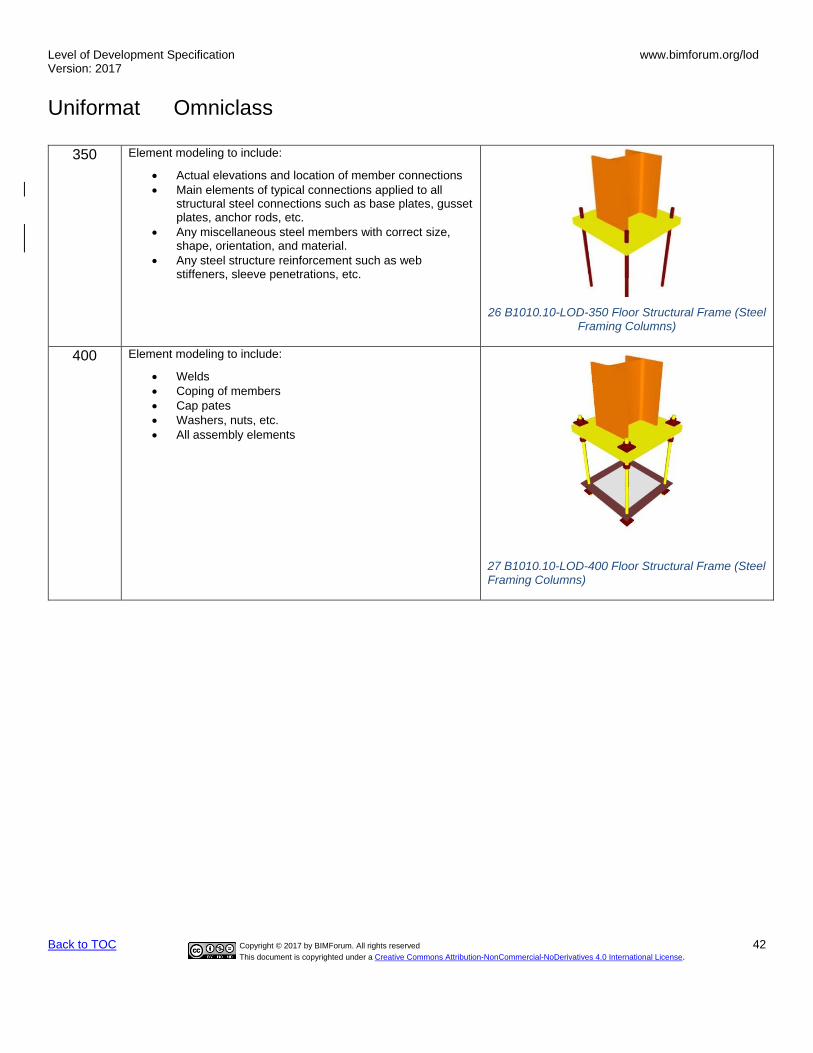
Level of Development Specification Version: 2017
www.bimforum.org/lod
Uniformat Omniclass
Back to TOC Copyright © 2017 by BIMForum. All rights reserved 42
This document is copyrighted under a Creative Commons Attribution-NonCommercial-NoDerivatives 4.0 International License.
350 Element modeling to include:
• Actual elevations and location of member connections
• Main elements of typical connections applied to all structural steel connections such as base plates, gusset plates, anchor rods, etc.
• Any miscellaneous steel members with correct size, shape, orientation, and material.
• Any steel structure reinforcement such as web stiffeners, sleeve penetrations, etc.
26 B1010.10-LOD-350 Floor Structural Frame (Steel Framing Columns)
400 Element modeling to include:
• Welds
• Coping of members
• Cap pates
• Washers, nuts, etc.
• All assembly elements
27 B1010.10-LOD-400 Floor Structural Frame (Steel Framing Columns)

Level of Development Specification Version: 2017
www.bimforum.org/lod
Uniformat Omniclass
Back to TOC Copyright © 2017 by BIMForum. All rights reserved 43
This document is copyrighted under a Creative Commons Attribution-NonCommercial-NoDerivatives 4.0 International License.
B1010.10.40 21-02 10 10 10 40 Floor Structural Frame (Steel Framing Beams)
Associated Masterformat Sections: 05 10 00 / 05 20 00 / 05 21 23
100 See B10
200 See B1010
300 Element modeling to include:
• Specific sizes of main horizontal structural members modeled per defined structural grid with correct orientation, slope and elevation
•
28 B1010.10-LOD-300 Floor Structural Frame (Steel Framing Beams)
350 Element modeling to include:
• Actual elevations and location of member connections
• Main elements of typical connections applied to all structural steel connections such as base plates, gusset plates, anchor rods, etc.
• Any miscellaneous steel members with correct size, shape, orientation and material
• Any steel structure reinforcement such as web stiffeners, sleeve penetrations, etc.
29 B1010.10-LOD-350 Floor Structural Frame (Steel Framing Beams)
400 Element modeling to include:
• Welds
• Coping of members
• Bent plates, cap pates, etc.
• Bolts, washers, nuts, etc.
• All assembly elements
30 B1010.10-LOD-400 Floor Structural Frame (Steel Framing Beams)

Level of Development Specification Version: 2017
www.bimforum.org/lod
Uniformat Omniclass
Back to TOC Copyright © 2017 by BIMForum. All rights reserved 44
This document is copyrighted under a Creative Commons Attribution-NonCommercial-NoDerivatives 4.0 International License.
B1010.10.50 21-02 10 10 10 50 Floor Structural Frame (Steel Framing Bracing Rods)
Associated Masterformat Sections: 05 10 00
100 See B10
200 See B1010
300 Element modeling to include:
• Specific sizes of main structural braces modeled per defined structural grid
31 B1010.100-LOD-300 Floor Structural Frame (Steel Framing Bracing Rods)
350 Element modeling to include:
• Connection details
• Actual elevations and location of member connections
• Main elements of typical connections applied to all structural steel connections such as base plates, gusset plates, anchor rods, etc.
• Any miscellaneous steel members with correct size, shape, orientation and material
32 B1010.100-LOD-350 Floor Structural Frame (Steel Framing Bracing Rods)
400 Element modeling to include:
• Welds
• Clevis
• Bolts, washers, nuts, etc.
• All assembly elements
33 B1010.100-LOD-400 Floor Structural Frame (Steel Framing Bracing Rods)

Level of Development Specification Version: 2017
www.bimforum.org/lod
Uniformat Omniclass
Back to TOC Copyright © 2017 by BIMForum. All rights reserved 45
This document is copyrighted under a Creative Commons Attribution-NonCommercial-NoDerivatives 4.0 International License.
B1010.10.60 21-02 10 10 10 60 Floor Structural Frame (Steel Joists)
Associated Masterformat Sections: 05 10 00 / 05 20 00 / 05 21 23
100 See B10
200 Element modeling to include:
• Approximate depth
300
Element modeling to include:
• Joist size, depth, slope, and material
• Spacing and end elevations
• Joist seat depth
•
35 B1010.10-LOD-300 Floor Structural Frame (Steel Joists)
34 B1010.10-LOD-200 Floor Structural Frame (Steel Joists)

Level of Development Specification Version: 2017
www.bimforum.org/lod
Uniformat Omniclass
Back to TOC Copyright © 2017 by BIMForum. All rights reserved 46
This document is copyrighted under a Creative Commons Attribution-NonCommercial-NoDerivatives 4.0 International License.
350 Element modeling to include, information needed for cross trade collaboration such as:
• Actual final joist profile locations with accurate panel points
• Joist bridging and lateral braces.
• Fire protection coating
• Any miscellaneous steel pertaining to the joist
• Joist seat width
• Erection details for installation
• Chord and web member section profiles are defined
• Joist layout in coordination with metal deck fasteners would be confirmed
• Non-standard joist seat depths and\or sloping joist seat
36 B1010.10-LOD-350 Floor Structural Frame (Steel Joists)
400 Element modeling to include:
• Welds
• Connection plates
• Member fabrication part number
• Quantity
• Spacing
• Anchorage
• Material required for proper installation
• Mark identification that correlates with bill of material
Type of shop paint if required
37 B1010.10-LOD-400 Floor Structural Frame (Steel Joists)
B1010.10.70 21-02 10 10 10 70 Floor Structural Framing (Cold Formed Metal Framing)
Associated Masterformat Sections: 05 10 00 / 05 42 00 / 05 44 00

Level of Development Specification Version: 2017
www.bimforum.org/lod
Uniformat Omniclass
Back to TOC Copyright © 2017 by BIMForum. All rights reserved 47
This document is copyrighted under a Creative Commons Attribution-NonCommercial-NoDerivatives 4.0 International License.
100 See B10
200 Element modeling to include:
• Rough architectural masses
• Approximate member depth
• Desired member spacing
300 Element modeling to include:
• floor element with design-specified locations and geometries
350 Element modeling to include:
• Members modeled at any interface with wall edges (top, bottom, sides) or opening through wall
• Bridging or straps
400 Element modeling to include:
• Welds
• Connections
• Member fabrication part number
• Any part required for complete installation
B1010.10 21-02 10 10 10 Floor Structural Frame (Masonry Framing)
Includes: Structural elements required for support of floor construction within basements and above grade. Includes columns, girders, beams, trusses, joists. Includes cast-in-place concrete, precast concrete, unit masonry, metal framed, and wood framed systems. Includes framed and sleeved openings for services. Includes Floor Construction Supplementary Components as appropriate.
Associated Masterformat Sections: 04 20 00
100 See B10

Level of Development Specification Version: 2017
www.bimforum.org/lod
Uniformat Omniclass
Back to TOC Copyright © 2017 by BIMForum. All rights reserved 48
This document is copyrighted under a Creative Commons Attribution-NonCommercial-NoDerivatives 4.0 International License.
200 See B10
38 B1010.10-LOD-200 Floor Structural Frame (Masonry Framing)
300 Element modeling to include:
• floor element with design-specified locations and geometries
39 B1010.10-LOD-300 Floor Structural Frame (Masonry Framing)
350 Element modeling to include:
• Members modeled at any interface with wall edges (top, bottom, sides) or opening through wall
• Any regions that would impact coordination with other systems such as but not limited to:
o Bond Beam & Lintel Regions o Reinforcing & Embed Regions o Jam Regions o Any other grouted regions
40 B1010.10-LOD-350 Floor Structural Frame (Masonry Framing)

Level of Development Specification Version: 2017
www.bimforum.org/lod
Uniformat Omniclass
Back to TOC Copyright © 2017 by BIMForum. All rights reserved 49
This document is copyrighted under a Creative Commons Attribution-NonCommercial-NoDerivatives 4.0 International License.
400 Element modeling to include:
• Reinforcing
• Connections
• Grouting Material
• Jams
• Bond Beams
• Lintels
• Member fabrication part number
• Any part required for complete installation
41 B1010.10-LOD-400 Floor Structural Frame (Masonry Framing)
B1010.10.80 21-02 10 10 10 80 Floor Structural Frame (Wood Floor Trusses)
Associated Masterformat Sections: 06 11 00 / 06 13 26 / 06 17 53
100 See B10

Level of Development Specification Version: 2017
www.bimforum.org/lod
Uniformat Omniclass
Back to TOC Copyright © 2017 by BIMForum. All rights reserved 50
This document is copyrighted under a Creative Commons Attribution-NonCommercial-NoDerivatives 4.0 International License.
200 Element modeling to include:
• Top chord or bottom chord bearing
• Truss orientation
• Approximate depth
• Approximate width
• Truss orientation
• Approximate centerline location of individual trusses
42 B1010.10-LOD-200 Floor Structural Frame (Wood Floor Trusses)
300 Element modeling to include:
• Truss size, depth, and material with sloping geometry
• Spacing and end elevations
• Support locations
43 B1010.10-LOD-300 Floor Structural Frame (Wood Floor Trusses)
350 Element modeling to include:
• Actual final truss profile with accurate panel points
• Bridging and lateral braces
• Fire protection coating
• Any miscellaneous framing pertaining the truss
• Erection details for installation
• Chord and web member section profiles are accurately defined
• Truss layout in coordination with deck fasteners would be confirmed
• Hold down locations for large bolts.
44 B1010.10-LOD-350 Floor Structural Frame (Wood Floor Trusses)
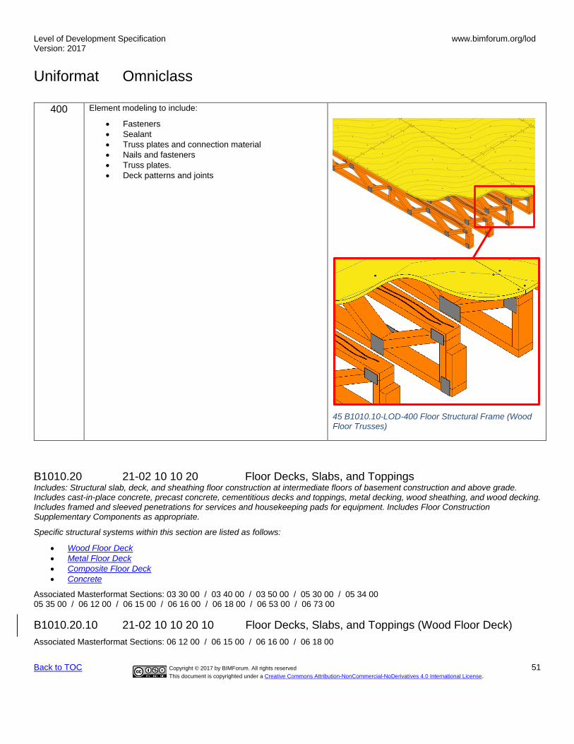
Level of Development Specification Version: 2017
www.bimforum.org/lod
Uniformat Omniclass
Back to TOC Copyright © 2017 by BIMForum. All rights reserved 51
This document is copyrighted under a Creative Commons Attribution-NonCommercial-NoDerivatives 4.0 International License.
400 Element modeling to include:
• Fasteners
• Sealant
• Truss plates and connection material
• Nails and fasteners
• Truss plates.
• Deck patterns and joints
45 B1010.10-LOD-400 Floor Structural Frame (Wood Floor Trusses)
B1010.20 21-02 10 10 20 Floor Decks, Slabs, and Toppings Includes: Structural slab, deck, and sheathing floor construction at intermediate floors of basement construction and above grade. Includes cast-in-place concrete, precast concrete, cementitious decks and toppings, metal decking, wood sheathing, and wood decking. Includes framed and sleeved penetrations for services and housekeeping pads for equipment. Includes Floor Construction Supplementary Components as appropriate.
Specific structural systems within this section are listed as follows:
• Wood Floor Deck
• Metal Floor Deck
• Composite Floor Deck
• Concrete
Associated Masterformat Sections: 03 30 00 / 03 40 00 / 03 50 00 / 05 30 00 / 05 34 00 05 35 00 / 06 12 00 / 06 15 00 / 06 16 00 / 06 18 00 / 06 53 00 / 06 73 00
B1010.20.10 21-02 10 10 20 10 Floor Decks, Slabs, and Toppings (Wood Floor Deck)
Associated Masterformat Sections: 06 12 00 / 06 15 00 / 06 16 00 / 06 18 00
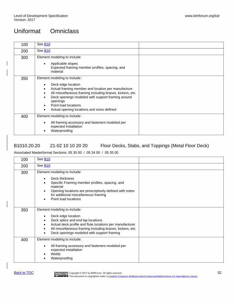
Level of Development Specification Version: 2017
www.bimforum.org/lod
Uniformat Omniclass
Back to TOC Copyright © 2017 by BIMForum. All rights reserved 52
This document is copyrighted under a Creative Commons Attribution-NonCommercial-NoDerivatives 4.0 International License.
100 See B10
200 See B10
300 Element modeling to include:
• Applicable slopes Expected framing member profiles, spacing, and material
350 Element modeling to include:
• Deck edge location
• Actual framing member and location per manufacture
• All miscellaneous framing including braces, kickers, etc.
• Deck openings modeled with support framing around openings
• Point load locations
• Actual opening locations and sizes defined
400 Element modeling to include:
• All framing accessory and fasteners modeled per expected installation
• Waterproofing
B1010.20.20 21-02 10 10 20 20 Floor Decks, Slabs, and Toppings (Metal Floor Deck)
Associated Masterformat Sections: 05 30 00 / 05 34 00 / 05 35 00
100 See B10
200 See B10
300 Element modeling to include:
• Deck thickness
• Specific Framing member profiles, spacing, and material
• Opening locations are prescriptively defined with notes for additional miscellaneous framing
• Point load locations
350 Element modeling to include:
• Deck edge location
• Deck splice and end lap locations
• Actual deck profile and flute locations per manufacturer
• All miscellaneous framing including braces, kickers, etc.
• Deck openings modeled with support framing
400 Element modeling to include:
• All framing accessory and fasteners modeled per expected installation
• Welds
• Waterproofing

Level of Development Specification Version: 2017
www.bimforum.org/lod
Uniformat Omniclass
Back to TOC Copyright © 2017 by BIMForum. All rights reserved 53
This document is copyrighted under a Creative Commons Attribution-NonCommercial-NoDerivatives 4.0 International License.
B1010.20.30 21-02 10 10 20 30 Floor Decks, Slabs, and Toppings (Composite Floor Deck)
Associated Masterformat Sections: 06 73 00
100 See B10
200 See B10
300 Element modeling to include:
• Specific deck thickness
• Specific Framing member profiles, spacing, material
• Opening locations are prescriptively defined with notes for additional miscellaneous framing
350 Element modeling to include:
• Deck edge location
• Actual deck profile and flute locations per manufacture
• Deck splice and end lap locations
• Actual framing member and location per manufacture
• All miscellaneous framing including deck support, deck closure, shear studs, etc.
• Slab openings modeled with support framing around openings
• Point load locations
• Slab reinforcing modeled if specified in BXP
400 Element modeling to include:
• All framing accessory and fasteners modeled per expected installation
• All slab reinforcing
• Welds
• Waterproofing
B1010.20.40 21-02 10 10 20 40 Floor Decks, Slabs, and Toppings (Concrete)
Associated Masterformat Sections: 03 30 00 / 03 40 00 / 03 50 00
100 See B10
200 Element modeling to include:
• Type of structural concrete system (e.g. cast-in-place or precast)
• Approximate geometry (e.g. depth) of structural elements

Level of Development Specification Version: 2017
www.bimforum.org/lod
Uniformat Omniclass
Back to TOC Copyright © 2017 by BIMForum. All rights reserved 54
This document is copyrighted under a Creative Commons Attribution-NonCommercial-NoDerivatives 4.0 International License.
300 Element modeling to include:
• Specific sizes and locations of main concrete structural members modeled per defined structural grid with correct orientation
• All sloping surfaces included in model element with exception of elements affected by manufacturer selection
350 Element modeling to include:
• Reinforcement called out, modeled if required by the BXP, typically only in congested areas
• Chamfer
• Pour joints and sequences to help identify reinforcing lap splice locations, scheduling, etc.
• Expansion Joints
• Embeds and anchor rods
• Post-tension profile and strands modeled if required by the BXP
• Penetrations for items such as MEP
• Any permanent forming or shoring components
• Shear reinforcing and stud rails
400 Element modeling to include:
• All reinforcement including post tension elements detailed and modeled
• Finishes
B1010.20.41 21-02 10 10 10 41 Precast Structural Double Tee (Concrete)
Includes: Structural elements required for support of floor construction within basements and above grade. Includes columns, girders, beams, trusses, joists. Includes cast-in-place concrete, precast concrete, unit masonry, metal framed, and wood framed systems. Includes framed and sleeved openings for services. Includes Floor Construction Supplementary Components as appropriate
Associated Masterformat Sections: 03 30 00 / 03 40 00 / 04 20 00 / 05 10 00 / 05 20 00 05 21 23 / 05 42 00 / 05 44 00 / 06 11 00 / 06 13 00 / 06 13 26 / 06 17 33 / 06 17 36 06 17 53 / 06 18 13 / 06 18 16 / 06 50 00
100 See B10B10
200 Element modeling to include:
• Approximate geometry (e.g. depth) of structural elements
46 B1010.20 – LOD 200 Precast Structural Double Tee (Concrete)

Level of Development Specification Version: 2017
www.bimforum.org/lod
Uniformat Omniclass
Back to TOC Copyright © 2017 by BIMForum. All rights reserved 55
This document is copyrighted under a Creative Commons Attribution-NonCommercial-NoDerivatives 4.0 International License.
300 Element modeling to include:
• Specific sizes and locations of main concrete structural members modeled per defined structural grid with correct orientation
• Concrete defined per spec (strength, air entrainment, aggregate size, etc.)
• All sloping surfaces included in model element with exception of elements affected by manufacturer selection
47 B1010.20 – LOD 300 Precast Structural Double Tee (Concrete)
350 Element modeling to include:
• Reinforcing Post-tension profiles and strand locations
• Reinforcement called out, modeled if required by the BXP, typically only in congested areas
• Chamfer
• Pour joints and sequences to help identify reinforcing lap splice locations, scheduling, etc.
• Expansion Joints
• Lifting devices
• Embeds and anchor rods
• Penetrations for items such as MEP
• Any permanent forming or shoring components
48 B1010.20 – LOD 350 Precast Structural Double Tee (Concrete)
400 Element modeling to include:
• All reinforcement including post tension elements detailed and modeled
• Finishes
49 B1010.20 – LOD 400 Precast Structural Double Tee (Concrete)
B1010.30 21-02 10 10 30 Balcony Floor Construction TBD
B1010.40 21-02 10 10 40 Mezzanine Floor Construction TBD
B1010.50 21-02 10 10 50 Ramps TBD
B1010.90 21-02 10 10 50 Floor Construction Supplementary Components TBD
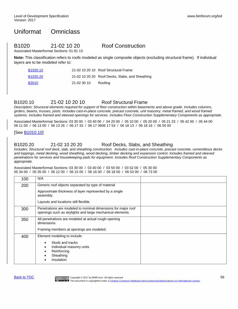
Level of Development Specification Version: 2017
www.bimforum.org/lod
Uniformat Omniclass
Back to TOC Copyright © 2017 by BIMForum. All rights reserved 56
This document is copyrighted under a Creative Commons Attribution-NonCommercial-NoDerivatives 4.0 International License.
B1020 21-02 10 20 Roof Construction Associated Masterformat Sections: 01 81 13
Note: This classification refers to roofs modeled as single composite objects (excluding structural frame). If individual
layers are to be modeled refer to:
B1020.10 21-02 10 20 10 Roof Structural Frame
B1020.20 21-02 10 20 20 Roof Decks, Slabs, and Sheathing
B3010 21-02 30 10 Roofing
B1020.10 21-02 10 20 10 Roof Structural Frame Description: Structural elements required for support of floor construction within basements and above grade. Includes columns, girders, beams, trusses, joists. Includes cast-in-place concrete, precast concrete, unit masonry, metal framed, and wood framed systems. Includes framed and sleeved openings for services. Includes Floor Construction Supplementary Components as appropriate.
Associated Masterformat Sections: 03 30 00 / 03 40 00 / 04 20 00 / 05 10 00 / 05 20 00 / 05 21 23 / 05 42 00 / 05 44 00 06 11 00 / 06 13 00 / 06 13 26 / 06 17 33 / 06 17 3606 17 53 / 06 18 13 / 06 18 16 / 06 50 00
[See B1010.10]
B1020.20 21-02 10 20 20 Roof Decks, Slabs, and Sheathing Includes: Structural roof deck, slab, and sheathing construction. Includes cast-in-place concrete, precast concrete, cementitious decks and toppings, metal decking, wood sheathing, wood decking, timber decking and expansion control. Includes framed and sleeved penetrations for services and housekeeping pads for equipment. Includes Roof Construction Supplementary Components as appropriate.
Associated Masterformat Sections: 03 30 00 / 03 40 00 / 03 50 00 / 03 52 00 / 05 30 00 05 34 00 / 05 35 00 / 06 12 00 / 06 15 00 / 06 16 00 / 06 18 00 / 06 53 00 / 06 73 00
100 N/A
200 Generic roof objects separated by type of material
Approximate thickness of layer represented by a single assembly.
Layouts and locations still flexible.
300 Penetrations are modeled to nominal dimensions for major roof openings such as skylights and large mechanical elements.
350 All penetrations are modeled at actual rough-opening dimensions.
Framing members at openings are modeled.
400 Element modeling to include:
• Studs and tracks
• Individual masonry units
• Reinforcing
• Sheathing
• Insulation
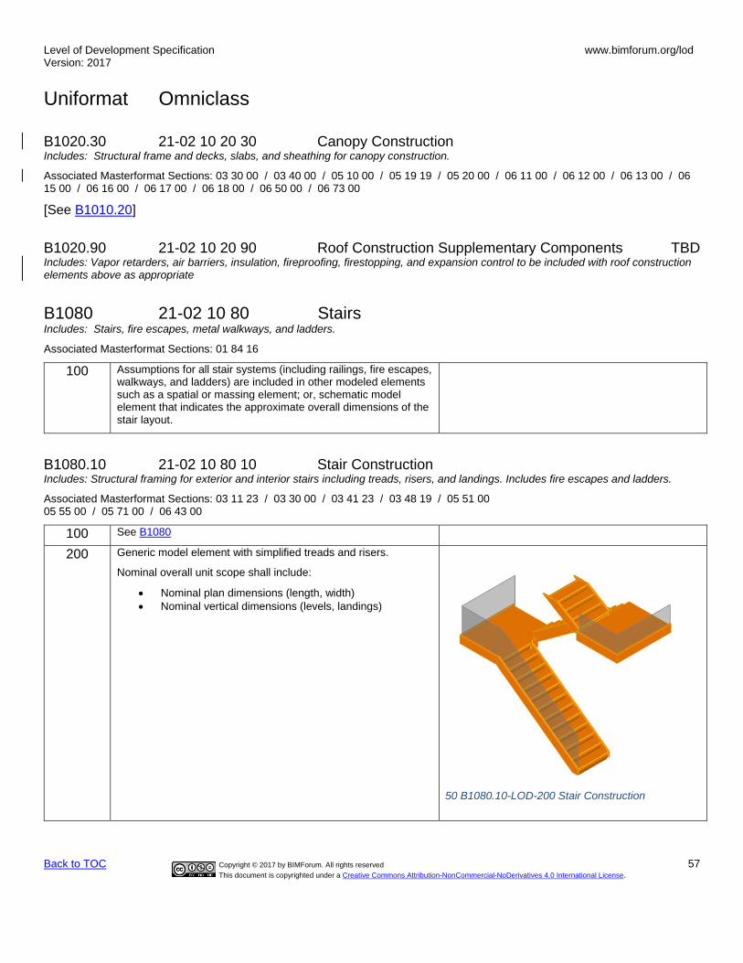
Level of Development Specification Version: 2017
www.bimforum.org/lod
Uniformat Omniclass
Back to TOC Copyright © 2017 by BIMForum. All rights reserved 57
This document is copyrighted under a Creative Commons Attribution-NonCommercial-NoDerivatives 4.0 International License.
B1020.30 21-02 10 20 30 Canopy Construction Includes: Structural frame and decks, slabs, and sheathing for canopy construction.
Associated Masterformat Sections: 03 30 00 / 03 40 00 / 05 10 00 / 05 19 19 / 05 20 00 / 06 11 00 / 06 12 00 / 06 13 00 / 06 15 00 / 06 16 00 / 06 17 00 / 06 18 00 / 06 50 00 / 06 73 00
[See B1010.20]
B1020.90 21-02 10 20 90 Roof Construction Supplementary Components TBD Includes: Vapor retarders, air barriers, insulation, fireproofing, firestopping, and expansion control to be included with roof construction elements above as appropriate
B1080 21-02 10 80 Stairs Includes: Stairs, fire escapes, metal walkways, and ladders.
Associated Masterformat Sections: 01 84 16
100 Assumptions for all stair systems (including railings, fire escapes, walkways, and ladders) are included in other modeled elements such as a spatial or massing element; or, schematic model element that indicates the approximate overall dimensions of the stair layout.
B1080.10 21-02 10 80 10 Stair Construction Includes: Structural framing for exterior and interior stairs including treads, risers, and landings. Includes fire escapes and ladders.
Associated Masterformat Sections: 03 11 23 / 03 30 00 / 03 41 23 / 03 48 19 / 05 51 00 05 55 00 / 05 71 00 / 06 43 00
100 See B1080
200 Generic model element with simplified treads and risers.
Nominal overall unit scope shall include:
• Nominal plan dimensions (length, width)
• Nominal vertical dimensions (levels, landings)
50 B1080.10-LOD-200 Stair Construction

Level of Development Specification Version: 2017
www.bimforum.org/lod
Uniformat Omniclass
Back to TOC Copyright © 2017 by BIMForum. All rights reserved 58
This document is copyrighted under a Creative Commons Attribution-NonCommercial-NoDerivatives 4.0 International License.
300 Major stair support elements are modeled (stringers).
Element is accurate as to
• Riser count
• Riser height
• Tread width
• Nosing conditions, including top and bottom
• Landing geometry
51 B1080.10-LOD-300 Stair Construction
350 Secondary stair support elements are modeled (hangers, brackets, handrail connection points etc.).
52 B1080.10-LOD-350 Stair Construction
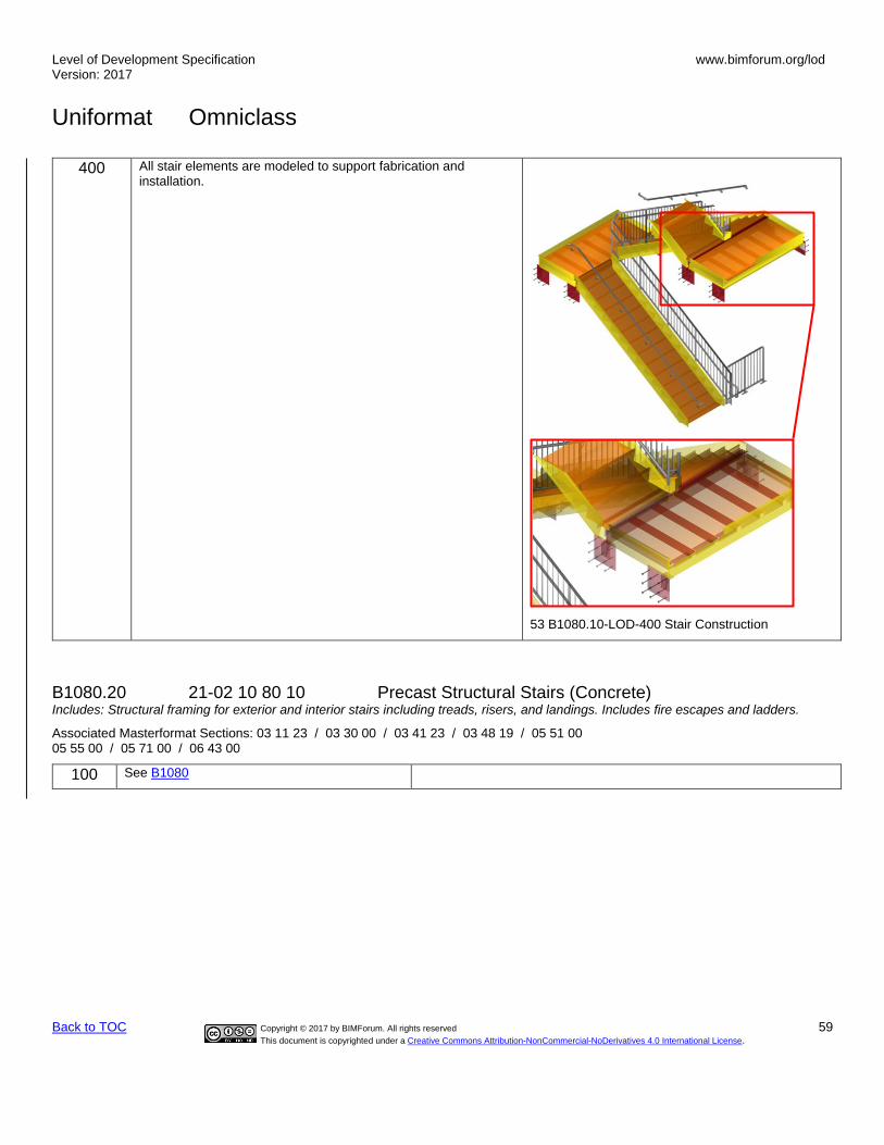
Level of Development Specification Version: 2017
www.bimforum.org/lod
Uniformat Omniclass
Back to TOC Copyright © 2017 by BIMForum. All rights reserved 59
This document is copyrighted under a Creative Commons Attribution-NonCommercial-NoDerivatives 4.0 International License.
400 All stair elements are modeled to support fabrication and installation.
53 B1080.10-LOD-400 Stair Construction
B1080.20 21-02 10 80 10 Precast Structural Stairs (Concrete) Includes: Structural framing for exterior and interior stairs including treads, risers, and landings. Includes fire escapes and ladders.
Associated Masterformat Sections: 03 11 23 / 03 30 00 / 03 41 23 / 03 48 19 / 05 51 00 05 55 00 / 05 71 00 / 06 43 00
100 See B1080

Level of Development Specification Version: 2017
www.bimforum.org/lod
Uniformat Omniclass
Back to TOC Copyright © 2017 by BIMForum. All rights reserved 60
This document is copyrighted under a Creative Commons Attribution-NonCommercial-NoDerivatives 4.0 International License.
200 Element modeling to include:
• Type of structural concrete system
• Approximate geometry (e.g. depth) of structural elements
55 B1080.10-LOD 200 Precast Structural Stairs (Concrete)
300 Element is accurate as to
• Riser count
• Riser height
• Tread width
• Nosing conditions, including top and bottom
• Landing geometry
56 B1080.10-LOD 300 Precast Structural Stairs (Concrete)

Level of Development Specification Version: 2017
www.bimforum.org/lod
Uniformat Omniclass
Back to TOC Copyright © 2017 by BIMForum. All rights reserved 61
This document is copyrighted under a Creative Commons Attribution-NonCommercial-NoDerivatives 4.0 International License.
350 Element modeling to include:
• Reinforcing Post-tension profiles and strand locations
• Reinforcement called out, modeled if required by the BXP, typically only in congested areas
• Pour joints and sequences to help identify reinforcing lap splice locations, scheduling, etc.
• Chamfer
• Expansion Joints
• Lifting devices
• Embeds and anchor rods
• Post-tension profile and strands modeled if required by the BXP
• All penetrations modeled to rough opening dimensions.
• Any permanent forming or shoring components
57 B1080.10-LOD 350 Precast Structural Stairs (Concrete)
400 Element modeling to include:
• All reinforcement including post tension elements detailed and modeled
• Finishes, , etc.
58 B1080.10-LOD 400 Precast Structural Stairs (Concrete)
B1080.30 21-02 10 80 30 Stair Soffits TBD
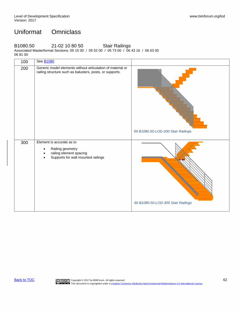
Level of Development Specification Version: 2017
www.bimforum.org/lod
Uniformat Omniclass
Back to TOC Copyright © 2017 by BIMForum. All rights reserved 62
This document is copyrighted under a Creative Commons Attribution-NonCommercial-NoDerivatives 4.0 International License.
B1080.50 21-02 10 80 50 Stair Railings Associated Masterformat Sections: 05 15 00 / 05 52 00 / 05 73 00 / 06 43 16 / 06 63 00 06 81 00
100 See B1080
200 Generic model elements without articulation of material or railing structure such as balusters, posts, or supports.
300 Element is accurate as to
• Railing geometry
• railing element spacing
• Supports for wall mounted railings
59 B1080.50-LOD-200 Stair Railings
60 B1080.50-LOD-300 Stair Railings

Level of Development Specification Version: 2017
www.bimforum.org/lod
Uniformat Omniclass
Back to TOC Copyright © 2017 by BIMForum. All rights reserved 63
This document is copyrighted under a Creative Commons Attribution-NonCommercial-NoDerivatives 4.0 International License.
400 [See Fundamental LOD Definitions]
B1080.60 21-02 10 80 60 Fire Escapes Associated Masterformat Sections: 05 51 23
[See B1080.10 and B1080.50]
B1080.70 21-02 10 80 70 Metal Walkways Includes: Catwalks and gratings over horizontal openings
Associated Masterformat Sections: 05 51 36 / 05 51 36.13 / 05 53 00
[See B1080.10 and B1080.50]
100 See B1080
200 Grating type
B1080.70 LOD 200 Grating
61 B1080.50-LOD-400 Stair Railings

Level of Development Specification Version: 2017
www.bimforum.org/lod
Uniformat Omniclass
Back to TOC Copyright © 2017 by BIMForum. All rights reserved 64
This document is copyrighted under a Creative Commons Attribution-NonCommercial-NoDerivatives 4.0 International License.
300 Element modeling to include:
• Grating type and overall geometry.
• Thickness
• Surface pattern showing span direction.
B1080.70 LOD 300 Grating
350 Element modeling to include:
• Panel layout and grating deck edges.
• Banding, openings, and grating penetrations.
B1080.70 LOD 350 Grating
400 Element modeling to include:
• Full fabrication connections
B1080.80 21-02 10 80 80 Ladders Associated Masterformat Sections: 05 51 33 / 05 51 33.13 / 05 51 33.16 / 05 51 33.23
[See B1080.10 and B1080.50]
B20 21-02 20 Exterior Vertical Enclosures Associated Masterformat Sections: 01 83 16
100 Solid mass model representing overall building volume; or, schematic wall elements that are not distinguishable by type or material.
Assembly depth/thickness and locations still flexible.

Level of Development Specification Version: 2017
www.bimforum.org/lod
Uniformat Omniclass
Back to TOC Copyright © 2017 by BIMForum. All rights reserved 65
This document is copyrighted under a Creative Commons Attribution-NonCommercial-NoDerivatives 4.0 International License.
B2010 21-02 20 10 Exterior Walls Includes: Exterior Wall Supplementary Components as appropriate. Includes Exterior Wall Opening Supplementary Components as appropriate. Includes: Solid wall construction that is composite in nature; in other words, multiple layers of materials to form an overall assembly.
Associated Masterformat Sections: 01 83 16
Note: This classification refers to walls modeled as single composite objects. If individual layers are to be modeled refer
to:
B2010.10 21-02 20 10 10 Exterior Wall Veneer
B2010.20 21-02 20 10 20 Exterior Wall Construction
B2010.30 21-02 20 10 30 Exterior Wall Interior Skin
100 See B20
200 Generic wall objects separated by type of material (e.g. brick wall vs. terracotta).
Approximate overall wall thickness represented by a single assembly.
Layouts and locations still flexible.
62 B2010-LOD-200 Exterior Walls
300 Single model element with specific overall thickness that accounts for veneer, structure, insulation, air space, and interior skin specified for the wall system. (Refer to LOD350 and LOD400 for individually modeled elements)
Penetrations are modeled to nominal dimensions for major wall openings such as windows, doors, and large mechanical elements.
63 B2010-LOD-300 Exterior Walls
350 May be modeled as a dingle model element.
Main structural members such as headers and jambs at openings are modeled.
All penetrations are modeled at actual rough-opening dimensions.
64 B2010-LOD-350 Exterior Walls

Level of Development Specification Version: 2017
www.bimforum.org/lod
Uniformat Omniclass
Back to TOC Copyright © 2017 by BIMForum. All rights reserved 66
This document is copyrighted under a Creative Commons Attribution-NonCommercial-NoDerivatives 4.0 International License.
B2010.10 21-02 20 10 10 Exterior Wall Veneer Includes: Nonstructural outside face elements of exterior walls. Includes precast concrete, unit masonry, EIFS, manufactured siding, and stucco Includes water repellents, coatings, and painting.
Associated Masterformat Sections: 03 40 00 / 04 20 00 / 04 26 13 / 04 42 00 / 04 43 13 04 70 00 / 05 19 13 / 06 20 13 / 06 61 00 / 07 19 00 / 07 24 00 / 07 42 00 / 07 44 00 07 46 00 / 09 24 00 / 09 24 23 / 09 90 00
100 N/A
200 Generic wall objects separated by type of material (e.g. brick wall vs. terracotta).
Approximate thickness of layer represented by a single assembly.
Layouts and locations still flexible.
300 Exterior wall veneer modeled as a separate element.
Specific wall modeled to actual dimensions.
Penetrations are modeled to nominal dimensions for major wall openings such as windows, doors, and large mechanical elements.
350 Exterior wall veneer modeled as a separate element.
All penetrations are modeled at actual rough-opening dimensions.
Precast concrete panels are individually modeled. Connection points are specified.
Connection to interfacing systems
Images notes:
• Wall veneer element
1 2
3
4
65 B2010.10-LOD-200 Exterior Wall Veneer
66 B2010.10-LOD-300 Exterior Wall Veneer
67 B2010.10-LOD-350 Exterior Wall Veneer
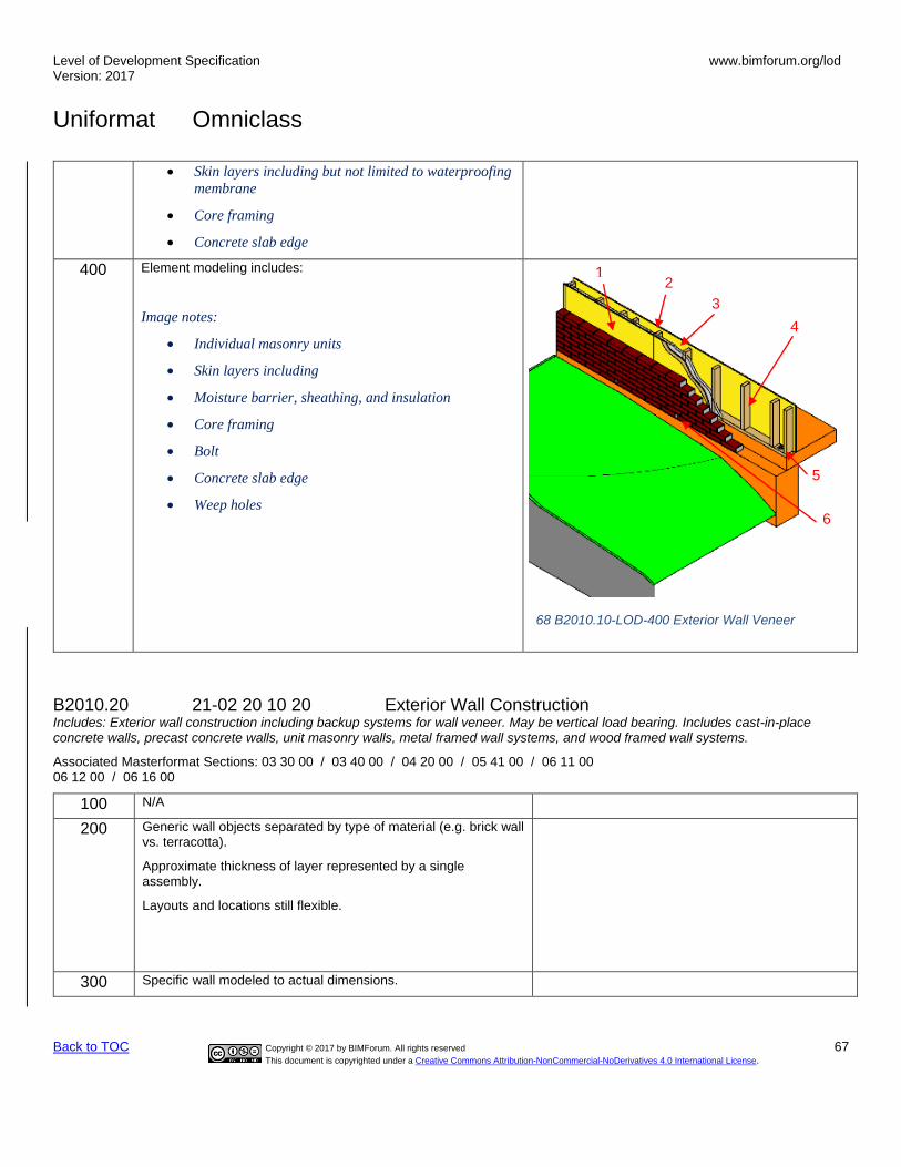
Level of Development Specification Version: 2017
www.bimforum.org/lod
Uniformat Omniclass
Back to TOC Copyright © 2017 by BIMForum. All rights reserved 67
This document is copyrighted under a Creative Commons Attribution-NonCommercial-NoDerivatives 4.0 International License.
• Skin layers including but not limited to waterproofing
membrane
• Core framing
• Concrete slab edge
400 Element modeling includes:
Image notes:
• Individual masonry units
• Skin layers including
• Moisture barrier, sheathing, and insulation
• Core framing
• Bolt
• Concrete slab edge
• Weep holes
B2010.20 21-02 20 10 20 Exterior Wall Construction Includes: Exterior wall construction including backup systems for wall veneer. May be vertical load bearing. Includes cast-in-place concrete walls, precast concrete walls, unit masonry walls, metal framed wall systems, and wood framed wall systems.
Associated Masterformat Sections: 03 30 00 / 03 40 00 / 04 20 00 / 05 41 00 / 06 11 00 06 12 00 / 06 16 00
100 N/A
200 Generic wall objects separated by type of material (e.g. brick wall vs. terracotta).
Approximate thickness of layer represented by a single assembly.
Layouts and locations still flexible.
300 Specific wall modeled to actual dimensions.
1 2
3
4
5
6
68 B2010.10-LOD-400 Exterior Wall Veneer
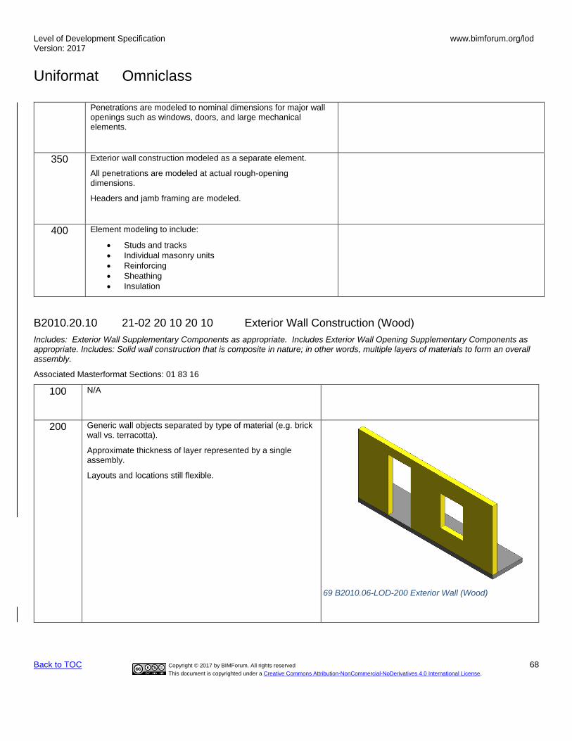
Level of Development Specification Version: 2017
www.bimforum.org/lod
Uniformat Omniclass
Back to TOC Copyright © 2017 by BIMForum. All rights reserved 68
This document is copyrighted under a Creative Commons Attribution-NonCommercial-NoDerivatives 4.0 International License.
Penetrations are modeled to nominal dimensions for major wall openings such as windows, doors, and large mechanical elements.
350 Exterior wall construction modeled as a separate element.
All penetrations are modeled at actual rough-opening dimensions.
Headers and jamb framing are modeled.
400 Element modeling to include:
• Studs and tracks
• Individual masonry units
• Reinforcing
• Sheathing
• Insulation
B2010.20.10 21-02 20 10 20 10 Exterior Wall Construction (Wood)
Includes: Exterior Wall Supplementary Components as appropriate. Includes Exterior Wall Opening Supplementary Components as appropriate. Includes: Solid wall construction that is composite in nature; in other words, multiple layers of materials to form an overall assembly.
Associated Masterformat Sections: 01 83 16
100
N/A
200 Generic wall objects separated by type of material (e.g. brick wall vs. terracotta).
Approximate thickness of layer represented by a single assembly.
Layouts and locations still flexible.
69 B2010.06-LOD-200 Exterior Wall (Wood)

Level of Development Specification Version: 2017
www.bimforum.org/lod
Uniformat Omniclass
Back to TOC Copyright © 2017 by BIMForum. All rights reserved 69
This document is copyrighted under a Creative Commons Attribution-NonCommercial-NoDerivatives 4.0 International License.
300 Specific wall modeled to actual dimensions.
Penetrations are modeled to nominal dimensions for major wall openings such as windows, doors, and large mechanical elements.
Shear panels
350 Wood framing is developed with sufficient elements to support detailed interface coordination with other systems such as MEP.
All penetrations are modeled at actual rough-opening dimensions.
Openings modeled with support framing around openings
Image notes:
1) Elements in red are critical wall support elements
that cannot be easily cut for coordination of MEP
opening through the walls.
2) Infill wood framing modeling may be omitted at this
LOD if stated in the BXP.
3) Cladding and sheathing are not shown for clarity in
this image.
2
1
70 B2010.06-LOD-300 Exterior Wall (Wood)
71 B2010.06-LOD-350 Exterior Wall (Wood)

Level of Development Specification Version: 2017
www.bimforum.org/lod
Uniformat Omniclass
Back to TOC Copyright © 2017 by BIMForum. All rights reserved 70
This document is copyrighted under a Creative Commons Attribution-NonCommercial-NoDerivatives 4.0 International License.
400 Wood framing is developed with sufficient elements that support the fabrication of the wood framing system.
Image notes:
1) Connection content is development in the wall
elements. This includes but is not limited to
fasteners, anchor rods, and other related hardware.
2) Cladding and sheathing are not shown for clarity in
this image.
72 B2010.06-LOD-400 Exterior Wall (Wood)
B2010.20.20 21-02 20 10 20 20 Exterior Wall Construction (Cold-Form Metal Framing)
Includes: Exterior Wall Supplementary Components as appropriate. Includes Exterior Wall Opening Supplementary Components as appropriate. Includes: Solid wall construction that is composite in nature; in other words, multiple layers of materials to form an overall assembly.
Associated Masterformat Sections: 01 83 16
100 N/A
1

Level of Development Specification Version: 2017
www.bimforum.org/lod
Uniformat Omniclass
Back to TOC Copyright © 2017 by BIMForum. All rights reserved 71
This document is copyrighted under a Creative Commons Attribution-NonCommercial-NoDerivatives 4.0 International License.
200 Generic wall objects separated by type of material (e.g. brick wall vs. terracotta).
Approximate thickness of layer represented by a single assembly.
Layouts and locations still flexible.
300 Specific wall modeled to actual dimensions.
Penetrations are modeled to nominal dimensions for major wall openings such as windows, doors, and large mechanical elements.
Shear panels
73 B2010.05-LOD-200 Exterior Wall (Cold-Form Metal Framing)
74 B2010.05-LOD-300 Exterior Wall (Cold-Form Metal Framing)

Level of Development Specification Version: 2017
www.bimforum.org/lod
Uniformat Omniclass
Back to TOC Copyright © 2017 by BIMForum. All rights reserved 72
This document is copyrighted under a Creative Commons Attribution-NonCommercial-NoDerivatives 4.0 International License.
350 Cold formed metal framing is developed with sufficient elements to support detailed interface coordination with other systems such as MEP.
All penetrations are modeled at actual rough-opening dimensions.
Openings modeled with support framing around openings
Image notes:
• Elements in red are critical wall support elements
that cannot be easily cut for coordination of MEP
opening through the walls.
• Diagonal bracing (kickers) that may be in the
above ceiling space are modeled for coordination
with other building content such as MEP passing
along the wall in the above ceiling spaces.
• Infill cold formed metal framing modeling (Orange)
may be omitted at this LOD if stated in the BXP.
• Cladding and sheathing are not shown for clarity in
this image.
2
1
3
75 B2010.05-LOD-350 Exterior Wall (Cold-Form Metal Framing)

Level of Development Specification Version: 2017
www.bimforum.org/lod
Uniformat Omniclass
Back to TOC Copyright © 2017 by BIMForum. All rights reserved 73
This document is copyrighted under a Creative Commons Attribution-NonCommercial-NoDerivatives 4.0 International License.
400 Cold formed metal framing is developed with sufficient elements that support the fabrication of the CFMF system.
Image notes:
• Connection content is development in the wall
elements. This includes but is not limited to
fasteners, clips, and other related hardware.
• Cladding and sheathing are not shown for clarity in
this image.
B2010.20.30 21-02 20 10 20 30 Exterior Wall Construction (Masonry)
Includes: Exterior Wall Supplementary Components as appropriate. Includes Exterior Wall Opening Supplementary Components as appropriate. Includes: Solid wall construction that is composite in nature; in other words, multiple layers of materials to form an overall assembly.
Associated Masterformat Sections: 01 83 16
100 N/A
1
76 B2010.05-LOD-400 Exterior Wall (Cold-Form Metal Framing)

Level of Development Specification Version: 2017
www.bimforum.org/lod
Uniformat Omniclass
Back to TOC Copyright © 2017 by BIMForum. All rights reserved 74
This document is copyrighted under a Creative Commons Attribution-NonCommercial-NoDerivatives 4.0 International License.
200 Generic wall objects separated by type of material (e.g. brick wall vs. terracotta).
Approximate thickness of layer represented by a single assembly.
Layouts and locations still flexible.
77 B2010.04-LOD-200 Exterior Wall (Masonry)
300 Specific wall modeled to actual dimensions.
Penetrations are modeled to nominal dimensions for major wall openings such as windows, doors, and large mechanical elements.
Shear panels
78 B2010.04-LOD-300 Exterior Wall (Masonry)
350 Element modeling to include:
• Members modeled at any interface with wall edges (top, bottom, sides) or opening through wall
• All penetrations are modeled at actual rough-opening dimensions.
• Openings modeled with support framing around openings
• Any regions that would impact coordination with other systems such as but not limited to:
o Bond Beam & Lintel Regions o Reinforcing & Embed Regions o Jam Regions o Any other grouted regions
79 B2010.04-LOD-350 Exterior Wall (Masonry)

Level of Development Specification Version: 2017
www.bimforum.org/lod
Uniformat Omniclass
Back to TOC Copyright © 2017 by BIMForum. All rights reserved 75
This document is copyrighted under a Creative Commons Attribution-NonCommercial-NoDerivatives 4.0 International License.
400 Element modeling to include:
• Reinforcing
• Connections
• Grouting Material
• Jams
• Bond Beams
• Lintels
• Member fabrication part number
• Any part required for complete installation
80 B2010.04-LOD-400 Exterior Wall (Masonry)

Level of Development Specification Version: 2017
www.bimforum.org/lod
Uniformat Omniclass
Back to TOC Copyright © 2017 by BIMForum. All rights reserved 76
This document is copyrighted under a Creative Commons Attribution-NonCommercial-NoDerivatives 4.0 International License.
B2010.20.40 21-02 20 10 20 40 Precast Wall Construction (Concrete)
Includes: Exterior wall construction including backup systems for wall veneer. May be vertical load bearing. Includes cast-in-place concrete walls, precast concrete walls, unit masonry walls, metal framed wall systems, and wood framed wall systems.
Associated Masterformat Sections: 03 30 00 / 03 40 00 / 04 20 00 / 05 41 00 / 06 11 00 06 12 00 / 06 16 00
100 N/A
200 Generic wall objects separated by type of material (e.g. brick wall vs. terracotta).
Approximate thickness of layer represented by a single assembly.
Layouts and locations still flexible.
300 Specific wall modeled to actual dimensions.
Penetrations are modeled to nominal dimensions for major wall openings such as windows, doors, and large mechanical elements.
Shear panels
350 Element modeling to include:
• Reinforcing Post-tension profiles and strand locations
• Reinforcement called out, modeled if required by the BXP, typically only in congested areas
• Pour joints and sequences to help identify reinforcing lap splice locations, scheduling, etc.
• Expansion Joints
• Lifting devices
• Embeds and anchor rods
• Post-tension profile and strands modeled if required by the BXP
• All penetrations are modeled at actual rough-opening dimensions.
• Any permanent forming or shoring components
• Chamfer, reveals, etc.
93 B2010.20– LOD 350 Precast Wall (Concrete)
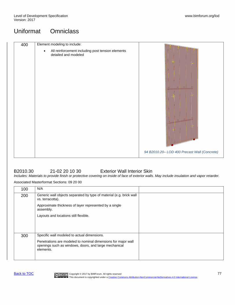
Level of Development Specification Version: 2017
www.bimforum.org/lod
Uniformat Omniclass
Back to TOC Copyright © 2017 by BIMForum. All rights reserved 77
This document is copyrighted under a Creative Commons Attribution-NonCommercial-NoDerivatives 4.0 International License.
400 Element modeling to include:
• All reinforcement including post tension elements detailed and modeled
94 B2010.20– LOD 400 Precast Wall (Concrete)
B2010.30 21-02 20 10 30 Exterior Wall Interior Skin Includes: Materials to provide finish or protective covering on inside of face of exterior walls. May include insulation and vapor retarder.
Associated Masterformat Sections: 09 20 00
100 N/A
200 Generic wall objects separated by type of material (e.g. brick wall vs. terracotta).
Approximate thickness of layer represented by a single assembly.
Layouts and locations still flexible.
300 Specific wall modeled to actual dimensions.
Penetrations are modeled to nominal dimensions for major wall openings such as windows, doors, and large mechanical elements.

Level of Development Specification Version: 2017
www.bimforum.org/lod
Uniformat Omniclass
Back to TOC Copyright © 2017 by BIMForum. All rights reserved 78
This document is copyrighted under a Creative Commons Attribution-NonCommercial-NoDerivatives 4.0 International License.
350 Exterior wall interior skin modeled as a separate element.
All openings modeled to rough opening dimensions.
400 Element modeling to include:
1) Studs and tracks
• Individual masonry units
• Reinforcing
• Wall board
• Insulation
B2010.40 21-02 20 10 40 Fabricated Exterior Wall Assemblies TBD Includes: Manufactured or fabricated assemblies that include exterior veneer and wall construction within one fabricated assembly and may also include interior skin. Includes Exterior Wall Supplementary Components as appropriate.
Associated Masterformat Sections: 04 25 00 / 07 42 63 / 07 44 63 / 08 44 00 / 08 45 00
Note: For Curtain Walls see:
B2020.30 21-02 20 20 30 Exterior Window Wall
B2010.50 21-02 20 10 50 Parapets Includes: Exterior wall construction above plane of roof.
Associated Masterformat Sections: 03 30 00 / 03 40 00 / 04 20 00 / 05 41 00 / 06 11 00 06 12 00 / 06 16 00
[See B2010, B2010.10, B2010.20, and B2010.30]
B2010.60 21-02 20 10 60 Equipment Screens Includes: Exterior wall construction to screen equipment from public view.
Associated Masterformat Sections: 03 40 00 / 04 20 00 / 08 92 00
[See B2010, B2010.10, B2010.20, and B2010.30]
B2010.80 21-02 20 10 80 Exterior Wall Supplementary Components TBD
B2010.90 21-02 20 10 90 Exterior Wall Opening Supplementary Components TBD
B2020 21-02 20 20 Exterior Windows Includes: Fixed or operable windows used singly and in multiples located in the exterior vertical enclosure. Includes Exterior Window Supplementary Components as appropriate. Includes windows units with louver blinds integrally set between glass panels. Includes metal, wood, plastic, and composite window units. May Include: Wall Opening Supplementary Components as appropriate.
Associated Masterformat Sections: 01 83 16 / 08 50 00
100 See B20
Level of Development Specification Version: 2017
www.bimforum.org/lod
Uniformat Omniclass
Back to TOC Copyright © 2017 by BIMForum. All rights reserved 79
This document is copyrighted under a Creative Commons Attribution-NonCommercial-NoDerivatives 4.0 International License.
200
Windows approximate in terms of location, size, count and type. Units are modeled as a simple, monolithic component; or represented with simple frame and glazing.
Nominal unit size is provided.
B2020.10 21-02 20 20 10 Exterior Operating Windows Includes: Window screens and storm windows.
Associated Masterformat Sections: 08 50 00 / 08 51 66 / 08 52 66 / 08 53 66 / 08 54 66 08 51 69 / 08 52 69 / 08 53 69 / 08 54 69
100 See B20
200 See B2020
300 Units are modeled based on specified location and nominal size. Outer geometry (profile) of window frame elements and glazing modeled in correct location
Operation is indicated.
350 Attachment method of window to structure
Embed elements
Backer rod and sealant
400 Detailed frame extrusion profiles
Glazing sub-components (gaskets)
Attachment components
1) End dam 2) Fasteners
B2020.20 21-02 20 20 20 Exterior Fixed Windows Associated Masterformat Sections: 08 50 00
[See B2020.10]
B2020.30 21-02 20 20 30 Exterior Window Wall Associated Masterformat Sections: 08 43 00
100 See B20
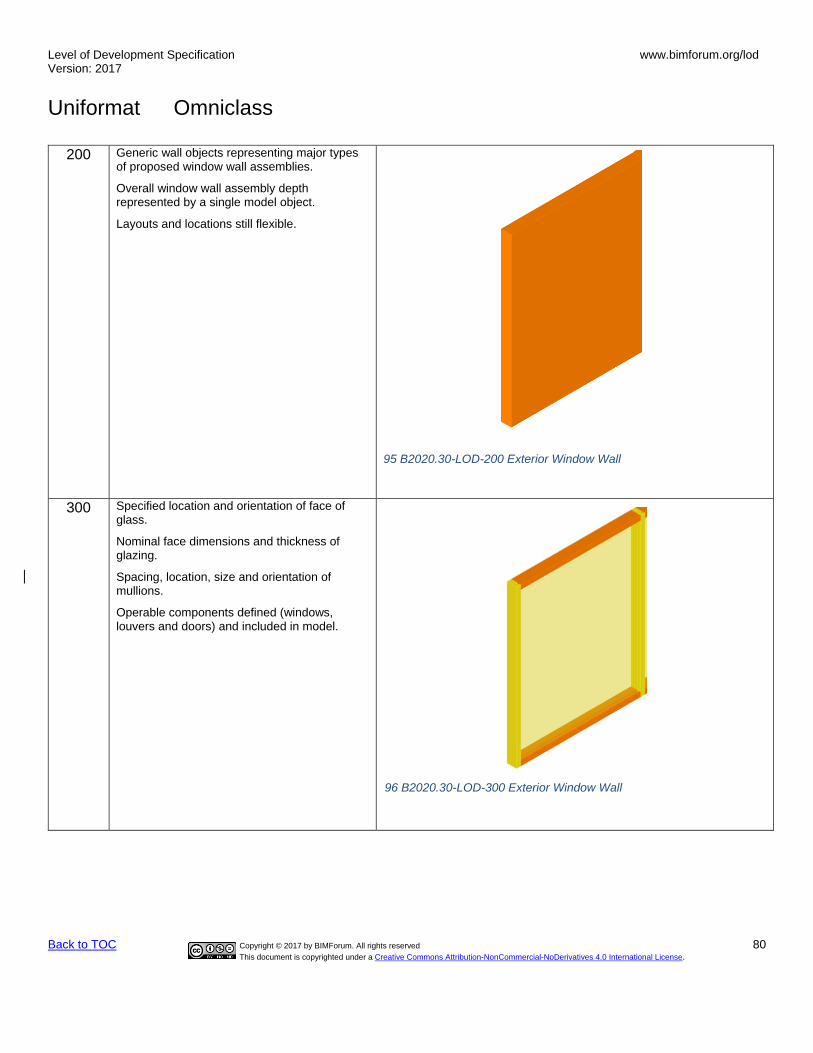
Level of Development Specification Version: 2017
www.bimforum.org/lod
Uniformat Omniclass
Back to TOC Copyright © 2017 by BIMForum. All rights reserved 80
This document is copyrighted under a Creative Commons Attribution-NonCommercial-NoDerivatives 4.0 International License.
200 Generic wall objects representing major types of proposed window wall assemblies.
Overall window wall assembly depth represented by a single model object.
Layouts and locations still flexible.
95 B2020.30-LOD-200 Exterior Window Wall
300 Specified location and orientation of face of glass.
Nominal face dimensions and thickness of glazing.
Spacing, location, size and orientation of mullions.
Operable components defined (windows, louvers and doors) and included in model.
96 B2020.30-LOD-300 Exterior Window Wall

Level of Development Specification Version: 2017
www.bimforum.org/lod
Uniformat Omniclass
Back to TOC Copyright © 2017 by BIMForum. All rights reserved 81
This document is copyrighted under a Creative Commons Attribution-NonCommercial-NoDerivatives 4.0 International License.
350 Mullion shapes and geometry defined.
Actual anchorage layouts and types defined and modeled.
Actual panel dimensions (including seating).
97 B2020.30-LOD-350 Exterior Window Wall

Level of Development Specification Version: 2017
www.bimforum.org/lod
Uniformat Omniclass
Back to TOC Copyright © 2017 by BIMForum. All rights reserved 82
This document is copyrighted under a Creative Commons Attribution-NonCommercial-NoDerivatives 4.0 International License.
400 Complete mullion extrusion profiles.
Interface details between wall systems (within) and wall and support systems including sealants, end dams, flashings and membranes.
98 B2020.30-LOD-400 Exterior Window Wall
B2020.50 21-02 20 20 50 Exterior Special Function Windows Includes: Exterior windows with special characteristics for a special function.
Associated Masterformat Sections: 08 56 00 / 08 55 00 / 08 88 39 / 08 56 19 / 08 56 46 08 56 49 / 08 88 49 / 08 56 53 / 08 88 53 / 08 88 56 / 08 56 63 / 08 56 73 / 08 75 00 08 80 00
[See B2020.10]

Level of Development Specification Version: 2017
www.bimforum.org/lod
Uniformat Omniclass
Back to TOC Copyright © 2017 by BIMForum. All rights reserved 83
This document is copyrighted under a Creative Commons Attribution-NonCommercial-NoDerivatives 4.0 International License.
B2050 21-02 20 50 Exterior Doors and Grilles Includes: Doors, grilles, and gates located in the exterior vertical enclosure. Includes screen and storm door assemblies. Includes Exterior Door Supplementary Components as appropriate. May Include: Wall Opening Supplementary Components as appropriate.
Associated Masterformat Sections: 01 83 16
100 Simple representation of a door unit. Size, count, and location are approximate.
200 Units are modeled as a simple, monolithic component; or represented with simple frame and panel.
Nominal unit size is provided.
B2050.10 21-02 20 50 10 Exterior Entrance Doors Includes: Exterior personnel door assemblies at main entrances. Includes automatic, revolving, balanced, and other special operating entrance doors, and sliding storefront wall systems.
Associated Masterformat Sections: 08 32 00 / 08 42 00 / 08 42 26 / 08 42 29 / 08 42 33 08 42 36 / 08 43 29
100 See B20
200 See B2050
300 Entrance door assemblies modeled by type to include the following:
Specific door panels and frames (if applicable).
Operation is specified. Spatial requirements for operation may be modeled if required by BXP.
350 Major framing elements are modeled at jambs and head.
Thresholds
Operation or mechanism enclosures are modeled.
All connections and interfaces modeled including brackets and supports.
400 Complete mullion extrusion profiles Actual panel size dimensions.
.
B2050.20 21-02 20 50 20 Exterior Utility Doors Includes: Exterior personnel door assemblies other than at main entrances.
Associated Masterformat Sections: 08 10 00

Level of Development Specification Version: 2017
www.bimforum.org/lod
Uniformat Omniclass
Back to TOC Copyright © 2017 by BIMForum. All rights reserved 84
This document is copyrighted under a Creative Commons Attribution-NonCommercial-NoDerivatives 4.0 International License.
100 See B20
200 See B2050
300 See B2050.10
350 See B2050.10
400 All connections and interfaces modeled including brackets, supports, sealants, and thresholds.
B2050.30 21-02 20 50 30 Exterior Oversize Doors Includes: Large exterior door assemblies to allow for passage of large objects involving various operating methods. Includes Exterior Door Supplementary Components as appropriate including operators and drive mechanisms.
Associated Masterformat Sections: 08 33 00 / 08 36 00 / 08 36 13 / 08 36 16 / 08 36 19 08 36 23 / 08 34 16
100 See B20
200 See B2050
300 Oversize door assemblies modeled by type to include the following:
Door panels with nominal dimensions.
Frames with nominal dimensions.
Clearance zones are modeled or accommodated by model checking software for operation of overhead doors (other than coiling doors).
Enclosures and motor housings are modeled with overall nominal dimensions.
350 Major framing elements in wall are modeled at jambs and head.
Attachment elements are modeled
400 All connections and interfaces modeled including brackets, supports, sealants, and thresholds.
B2050.40 21-02 20 50 40 Exterior Special Function Doors Includes: Exterior door assemblies for a variety of special functions and applications involving a variety of operating methods. Includes Exterior Door Supplementary Components as appropriate including controls and operators.
Associated Masterformat Sections: 08 30 00 / 08 34 13 / 08 34 19 / 08 34 46 / 08 34 49 08 34 53 / 08 34 63 / 08 34 73 / 08 38 00 / 08 39 00 / 08 88 49 / 08 88 53 / 08 88 56
[See B2050.20 or B2050.30]
B2050.60 21-02 20 50 60 Exterior Grilles Includes: Exterior devices of open construction to provide moveable barrier to provide access through wall or other divider.
Associated Masterformat Sections: 08 33 00 / 08 35 16

Level of Development Specification Version: 2017
www.bimforum.org/lod
Uniformat Omniclass
Back to TOC Copyright © 2017 by BIMForum. All rights reserved 85
This document is copyrighted under a Creative Commons Attribution-NonCommercial-NoDerivatives 4.0 International License.
100 See B20
200 See B2050
300 Grille assemblies modeled by type to include the following:
Nominal size of unit.
Operation is specified.
350 Major framing elements are modeled at jambs and head.
400 All connections and interfaces modeled including brackets, supports, sealants, and thresholds.
B2050.70 21-02 20 50 70 Exterior Gates Includes: Exterior devices of solid or open construction to provide moveable barrier to provide access through wall or other divider.
Associated Masterformat Sections: 08 34 56
[See B2050.60]
B2050.90 21-02 20 70 Exterior Door Supplementary Components Includes frames, hardware, glazing and louvers that are part of door to be included with exterior door elements above as appropriate.
These components are typically modeled as part of other assemblies listed in the tables above. Do not assign this Uniformat classification unless a supplementary component is modeled independently of another assembly.
Associated Masterformat Sections: 08 10 00 / 08 30 00 / 08 71 00 / 08 80 00 / 08 91 26
B2070 Exterior Louvers and Vents Includes: Exterior louvers which are not an integral part of mechanical equipment, including louvers connected to ducts.
Associated Masterformat Sections: 08 90 00
100 See B20
200 Generic model element that is indicative of approximate area and location of intended louver/vent.
B2070.10 21-02 20 70 10 Exterior Louvers Associated Masterformat Sections: 01 83 16 / 08 91 00
100 See B20
200 See B2070
300 Louver assembly modeled by type, indicative of area and location of intended louver/vent.
Accurate frame and blade boundary areas.
Opening for louver is cut from host wall

Level of Development Specification Version: 2017
www.bimforum.org/lod
Uniformat Omniclass
Back to TOC Copyright © 2017 by BIMForum. All rights reserved 86
This document is copyrighted under a Creative Commons Attribution-NonCommercial-NoDerivatives 4.0 International License.
350 Major framing elements are modeled at connection points.
Connection points are modeled.
400 All connections and interfaces modeled including brackets, supports, and sealants.
B2070.50 21-02 20 70 50 Exterior Vents Associated Masterformat Sections: 08 95 00
[See B2070.10]
B2080 21-02 20 80 Exterior Wall Appurtenances
Includes: Exterior enclosures, grilles and screens of wood, metal, plastic, and other materials for a variety of purposes including screening of equipment.
Associated Masterformat Sections:
[See B2050]
B2080.10 21-02 20 80 10 Exterior Fixed Grilles and Screens Includes: Exterior enclosures, grilles and screens of wood, metal, plastic, and other materials for a variety of purposes including screening of equipment.
Associated Masterformat Sections: 05 70 00 / 06 49 00 / 06 60 00 / 06 80 00 / 10 82 13
[See B2050.60]
B2080.30 21-02 20 80 30 Exterior Opening Protection Devices Includes: Manufactured items such as louvers, fins, shutters, demountable panels, awnings, and sun screens to provide sun control, privacy, security, insulation, and storm protection on exterior of windows, skylights, and entrances. Includes fixed and moveable, manually and electrically operated, and automatically controlled devices.
Associated Masterformat Sections: 10 71 00 / 10 71 13 / 10 71 16 / 10 73 13
[See B2010.60]
B2080.50 21-02 20 80 50 Exterior Balcony Walls and Railings Includes: Exterior enclosures, grilles and screens of wood, metal, plastic, and other materials for a variety of purposes including screening of equipment.
Associated Masterformat Sections: 03 30 00 / 03 40 00 / 04 20 00 / 05 41 00 / 06 11 00 06 16 00 / 05 52 00 / 05 73 00 / 06 43 16 / 06 63 00 / 06 81 00
[See B2010.50]
B2080.70 21-02 20 80 70 Exterior Fabrications Includes: Exterior fabrications of a variety of materials formed to various profiles for a variety of purposes including column covers, decorative metal, ornamental woodwork, and plaster fabrications.

Level of Development Specification Version: 2017
www.bimforum.org/lod
Uniformat Omniclass
Back to TOC Copyright © 2017 by BIMForum. All rights reserved 87
This document is copyrighted under a Creative Commons Attribution-NonCommercial-NoDerivatives 4.0 International License.
Associated Masterformat Sections: 03 49 00 / 05 50 00 / 05 58 13 / 05 70 00 / 06 44 00 06 60 00 / 06 61 00 / 06 80 00 / 09 27 00
[See Fundamental LOD Definitions]
B2080.80 21-02 20 80 80 Bird Control Devices Includes: Mechanical, electrical, physical, and chemical repellant systems, and protective devices.
Associated Masterformat Sections: 10 81 13
[See Fundamental LOD Definitions]
B2090 21-02 20 90 Exterior Wall Specialties
Includes: Complete fabrication of metal, wood, and fiberglass, including accessories and appurtenances. For example, clocks, below-grade egress assemblies, and window wells. Associated Masterformat Sections: 07 77 00 / 10 74 00 / 10 74 13 / 10 74 43 / 10 74 46
[See Fundamental LOD Definitions]
B30 21-02 30 Exterior Horizontal Enclosures Associated Masterformat Sections: 01 83 16
100 Solid mass model representing overall building volume; or, schematic wall elements that are not distinguishable by type or material.
Assembly depth/thickness and locations still flexible.
B3010 21-02 30 10 Roofing Associated Masterformat Sections: 01 83 19
100 See B30
200 Generic element representing roof exterior skin
300 Specific element representing roof insulation and exterior skin modeled to actual dimensions.
Surface slopes (e.g. tapered insulation) are modeled to actual dimensions.
Penetrations are modeled to nominal dimensions for major wall openings such as skylights, and large mechanical elements.
350 All penetrations are modeled at actual rough-opening dimensions.
Flashing

Level of Development Specification Version: 2017
www.bimforum.org/lod
Uniformat Omniclass
Back to TOC Copyright © 2017 by BIMForum. All rights reserved 88
This document is copyrighted under a Creative Commons Attribution-NonCommercial-NoDerivatives 4.0 International License.
B3010.10 21-02 30 10 10 Steep Slope Roofing Includes: Lapped roofing shingles, shakes and roofing tiles, including fastening and flashing products and methods. Includes Roofing Supplementary Components as appropriate.
Associated Masterformat Sections: 01 83 19 / 07 30 00 / 07 31 00 / 07 32 00 / 07 41 00 07 61 00 / 07 63 00
[See B3010]
B3010.50 21-02 30 10 50 Low-Slope Roofing Includes: Membrane roofing of various types and protected membrane roofing, including fastening and flashing products. Includes Roofing Supplementary Components as appropriate.
Associated Masterformat Sections: 01 83 19 / 07 50 00 / 07 55 00 / 07 55 63 / 07 76 00
[See B3010]
B3010.70 21-02 30 10 70 Canopy Roofing Includes: Roofing of various types over canopies. Includes Roofing Supplementary Components as appropriate.
Associated Masterformat Sections:
[See B1020]
B3010.70 21-02 30 10 70 Canopy Roofing Includes: Roofing of various types over canopies. Includes Roofing Supplementary Components as appropriate.
Associated Masterformat Sections:
[See B3010.10 or B3010.50]
B3010.90 21-02 30 10 90 Roofing Supplementary Components Includes: substrate boards, vapor retarder, air barriers, deck insulation, flashing and sheet metal, and expansion joints to be included with roofing elements above as appropriate.
These components are typically modeled as part of other assemblies listed in the tables above. Do not assign this Uniformat classification unless a supplementary component is modeled independently of another assembly.
Associated Masterformat Sections: 07 22 00 / 07 26 00 / 07 27 00 / 07 62 00 / 07 65 00 07 71 13 / 07 71 16 / 07 71 19 / 07 71 29 / 09 28 00
B3020 21-02 30 20 Roof Appurtenances Includes: Roof specialties and accessories installed on or in roofing or traffic bearing horizontal enclosure systems. Includes components for the management of rainwater, but excludes mechanical and structural items.
Associated Masterformat Sections:
100 See B30
200 See Fundamental LOD Definitions

Level of Development Specification Version: 2017
www.bimforum.org/lod
Uniformat Omniclass
Back to TOC Copyright © 2017 by BIMForum. All rights reserved 89
This document is copyrighted under a Creative Commons Attribution-NonCommercial-NoDerivatives 4.0 International License.
B3020.10 21-02 30 20 10 Roof Accessories Includes: Ladders, curbs, vents, walkways, and snow guards.
Associated Masterformat Sections: 05 51 33 / 07 72 00 / 07 72 13 / 07 72 23 / 07 72 26 07 72 46 / 07 72 53
100 See B30
200 See Fundamental LOD Definitions
300 Ladders: Specific assemblies indicating length and width. Required access/clearance space is modeled or accommodated by model checking software.
Walkways: Specific assemblies indicating length, width, and rail/guard height.
Vents: Specific assemblies indicating roof opening size. Roof opening element is included. Required service access space is modeled or accommodated by model checking software.
350 Ladders: Specific assemblies indicating length, width, and attachment/anchoring members.
Walkways: Specific assemblies indicating length, width, rail/guard height, and support/attachment/anchoring members.
Vents: Specific assemblies indicating roof opening size and attachment/anchoring members if applicable.
400 See Fundamental LOD Definitions
B3020.30 21-02 30 20 30 Roof Specialties Includes: Cupolas, spires, steeples, and weathervanes.
Associated Masterformat Sections: 10 74 00 / 10 74 23 / 10 74 26 / 10 74 29 / 10 74 33
[See Fundamental LOD Definitions]
B3020.70 21-02 30 20 70 Rainwater Management Includes: Components to manage rain water from roofing and traffic bearing horizontal enclosures. Includes: Conductor heads, gutters, downspouts, scuppers, and splash blocks.
Associated Masterformat Sections: 07 71 23 / 07 71 33 / 03 48 16
[See D2030.10 and D2030.20]
B3040 21-02 30 40 Traffic Bearing Horizontal Enclosures Includes: Horizontal enclosures that are also traffic bearing. Includes Horizontal Enclosure Supplementary Components as appropriate.
Associated Masterformat Sections: 01 83 16
100 See B30
200 See B3010
Level of Development Specification Version: 2017
www.bimforum.org/lod
Uniformat Omniclass
Back to TOC Copyright © 2017 by BIMForum. All rights reserved 90
This document is copyrighted under a Creative Commons Attribution-NonCommercial-NoDerivatives 4.0 International License.
B3040.10 21-02 30 40 10 Traffic Bearing Coatings Includes: Surface applied waterproofing exposed to weather and suitable for pedestrian or vehicular traffic.
Associated Masterformat Sections: 07 18 00
B3040.30 21-02 30 40 30 Horizontal Waterproofing Membrane Includes: Substrate board, deck insulation, vapor retarder, sheet metal flashing and trim, flexible flashing, and expansion joints.
Associated Masterformat Sections: 07 10 00
100 See B30
200 See B3040
300 Membrane assembly modeled by type to specified thickness.
Major openings such as shafts and hatches are modeled.
350 Individual material layers of membrane assembly are modeled separately.
All openings and penetrations are modeled.
Expansion joints are modeled indicating specific width.
B3040.50 21-02 30 40 50 Wear Surfaces Includes: Wearing surfaces on top of horizontal waterproofing membrane that are suitable for pedestrian or vehicular traffic.
Associated Masterformat Sections: 07 76 00 / 32 13 00 / 32 14 00
100 See B30
200 See B3040
300 Wear surface system modeled by type to specified thickness/depth.
Major openings such as shafts and hatches are modeled.
350 Individual system elements are modeled separately.
Pedestals are modeled and located properly, if applicable.
Expansion joints are modeled indicating specific width.
B3040.90 21-02 30 40 90 Horizontal Enclosure Supplementary Components Includes: Substrate board, deck insulation, vapor retarder, sheet metal flashing and trim, flexible flashing, and expansion joints to be included with horizontal enclosure elements above as appropriate.
These components are typically modeled as part of other assemblies listed in the tables above. Do not assign this Uniformat classification unless a supplementary component is modeled independently of another assembly.
Associated Masterformat Sections: 07 20 00 / 07 26 00 / 07 62 00 / 07 65 00 / 07 71 13 07 71 16 / 07 71 19 / 07 71 29 / 09 28 00

Level of Development Specification Version: 2017
www.bimforum.org/lod
Uniformat Omniclass
Back to TOC Copyright © 2017 by BIMForum. All rights reserved 91
This document is copyrighted under a Creative Commons Attribution-NonCommercial-NoDerivatives 4.0 International License.
B3060 21-02 30 60 Horizontal Openings Includes: Openings in horizontal enclosures including roofing and traffic bearing horizontal enclosures. Includes Horizontal Opening Supplementary Components as appropriate.
Associated Masterformat Sections:
100 See B30
200 See B2020
B3060.10 21-02 30 60 10 Roof Windows and Skylights Includes: Operable and non-operable roof windows. Includes: Skylights without framing with plastic and glass glazing. Includes: Skylights with framing.
Associated Masterformat Sections: 01 83 16 / 08 60 00 / 08 61 00 / 08 62 00 / 08 63 00 08 64 00 / 08 67 00
[See B2020.10]
B3060.50 21-02 30 60 50 Vents and Hatches Includes: Other roof openings such as roof hatches, smoke vents, and gravity roof ventilators.
Associated Masterformat Sections: 07 72 33 / 07 72 36
[See B3020.10]
B3060.90 21-02 30 60 90 Horizontal Opening Supplementary Components Includes: Frames, hardware, glazing, flashing, and joint sealants to be included with horizontal opening elements above as appropriate.
These components are typically modeled as part of other assemblies listed in the tables above. Do not assign this Uniformat classification unless a supplementary component is modeled independently of another assembly.
Associated Masterformat Sections: 08 75 00 / 08 80 00 / 07 60 00 / 07 92 00
B3080 21-02 30 80 Overhead Exterior Enclosures Includes: Exposed to weather construction under horizontal enclosure construction. Includes suspension and support systems, insulation, vapor retarders, and air barriers.
Associated Masterformat Sections: 01 83 16
100 See B30
200 Generic assemblies indicative of overall scope and approximate thickness/system depth of overhead enclosure.
B3080.10 21-02 30 80 10 Exterior Ceilings Associated Masterformat Sections: 07 42 00 / 07 44 00 / 09 20 00 / 09 54 00 / 09 56 00 09 90 00
100 See B30
200 See B3080

Level of Development Specification Version: 2017
www.bimforum.org/lod
Uniformat Omniclass
Back to TOC Copyright © 2017 by BIMForum. All rights reserved 92
This document is copyrighted under a Creative Commons Attribution-NonCommercial-NoDerivatives 4.0 International License.
300 Overall assembly modeled to specific system thickness including structural backing.
Location of expansion or control joints indicated, but not modeled.
350 Face material modeled to specific thickness.
Structural backing members including bracing/lateral framing/kickers are modeled.
Expansion or control joints are modeled to indicate specific width.
400 Individual elements of face material are modeled.
Structural backing members and all support members (kickers) are modeled including all connections.
Expansion or control joints are modeled.
B3080.20 21-02 30 80 20 Exterior Soffits Associated Masterformat Sections: 07 42 93 / 07 44 00 / 08 95 13 / 09 20 00 / 09 54 00 09 56 00 / 09 90 00
[See B3080.10]
B3080.30 21-02 30 80 30 Exterior Bulkheads Associated Masterformat Sections: 07 42 00 / 07 44 00 / 09 20 00 / 09 54 00 / 09 56 00 09 90 00
[See B3080.10]
Level of Development Specification Version: 2017
www.bimforum.org/lod
Uniformat Omniclass
Back to TOC Copyright © 2017 by BIMForum. All rights reserved 93
This document is copyrighted under a Creative Commons Attribution-NonCommercial-NoDerivatives 4.0 International License.
C 21-03 INTERIORS Associated Masterformat Sections: 01 84 00
C10 21-03 10 Interior Construction Associated Masterformat Sections: 01 84 13
100 A schematic model element or symbol that is not distinguishable by type or material.
Types, layouts, and locations are still flexible.
C1010 21-03 10 10 Interior Partitions Includes: Enclosures and partitions which are fixed and secured in place. Includes walls of concrete; and masonry; and wood and metal stud partitions with associated wall surfaces. Includes partitions of an open nature, such as wire mesh partitions. Partitions may be load bearing or non-load bearing. Includes Interior Partition Supplementary Components as appropriate.
Associated Masterformat Sections: 10 22 00 / 01 84 13
100 See C10
200 Generic wall objects separated by type of material (e.g. gypsum board vs. masonry).
Approximate overall wall thickness represented by a single assembly.
Layouts, locations, heights, and elevation profiles are still flexible.
C1010.10 21-03 10 10 10 Interior Fixed Partitions Includes: Enclosures and partitions which are fixed and secured in place. Includes walls of concrete; and masonry; and wood and metal stud partitions with associated wall surfaces. Includes partitions of an open nature, such as wire mesh partitions. Partitions may be load bearing or non-load bearing. Includes Interior Partition Supplementary Components as appropriate.
Associated Masterformat Sections: 03 30 00 / 03 40 00 / 04 20 00 / 05 41 00 / 06 11 00 / 09 20 00 / 10 22 13
100 See C10
200 See C1010
300 Composite model assembly by type with overall thickness that accounts for framing and finish specified for the wall system. (Refer to LOD350 and LOD400 for individually modeled elements)
Wall elements are modeled to specific layouts, locations, heights, and elevation profiles. Penetrations are modeled to nominal dimensions for major wall openings such as windows, doors, and large mechanical elements.
350 Structure and finish layers of partition assembly modeled as separate elements.

Level of Development Specification Version: 2017
www.bimforum.org/lod
Uniformat Omniclass
Back to TOC Copyright © 2017 by BIMForum. All rights reserved 94
This document is copyrighted under a Creative Commons Attribution-NonCommercial-NoDerivatives 4.0 International License.
All penetrations are modeled at actual rough-opening dimensions.
Major framing elements such as king studs, kickers, diagonal bracing, and headers are modeled.
400 Element modeling to include:
• Studs and tracks
• Bracing
• Insulation
• Sheathing or wall boards
• Openings/penetrations
C1010.10.10 21-03 10 10 10 10 Interior Wall (Masonry)
Includes: Enclosures and partitions which are fixed and secured in place. Includes walls of concrete; and masonry; and wood and metal stud partitions with associated wall surfaces. Includes partitions of an open nature, such as wire mesh partitions. Partitions may be load bearing or non-load bearing. Includes Interior Partition Supplementary Components as appropriate.
Associated Masterformat Sections: 10 22 00 / 01 84 13
100 See C10
200 See C1010
99 C1010.04-LOD-200 Interior Wall (Masonry)

Level of Development Specification Version: 2017
www.bimforum.org/lod
Uniformat Omniclass
Back to TOC Copyright © 2017 by BIMForum. All rights reserved 95
This document is copyrighted under a Creative Commons Attribution-NonCommercial-NoDerivatives 4.0 International License.
300 See C1010.10
350 Element modeling to include:
• Members modeled at any interface with wall edges (top, bottom, sides) or opening through wall
• All penetrations are modeled at actual rough-opening dimensions.
• Any regions that would impact coordination with other systems such as but not limited to:
o Bond Beam & Lintel Regions o Reinforcing & Embed Regions o Jam Regions
100 C1010.04-LOD-300 Interior Wall (Masonry)
101 C1010.04-LOD-350 Interior Wall (Masonry)

Level of Development Specification Version: 2017
www.bimforum.org/lod
Uniformat Omniclass
Back to TOC Copyright © 2017 by BIMForum. All rights reserved 96
This document is copyrighted under a Creative Commons Attribution-NonCommercial-NoDerivatives 4.0 International License.
400 Element modeling to include:
• Reinforcing
• Connections
• Grouting Material
• Jams
• Bond Beams
• Lintels
• Member fabrication part number
• Any part required for complete installation
102 C1010.04-LOD-400 Interior Wall (Masonry)
Level of Development Specification Version: 2017
www.bimforum.org/lod
Uniformat Omniclass
Back to TOC Copyright © 2017 by BIMForum. All rights reserved 97
This document is copyrighted under a Creative Commons Attribution-NonCommercial-NoDerivatives 4.0 International License.
C1010.10.20 21-03 10 10 10 20 Interior Wall (Cold-Form Metal Framing)
Includes: Enclosures and partitions which are fixed and secured in place. Includes walls of concrete; and masonry; and wood and metal stud partitions with associated wall surfaces. Includes partitions of an open nature, such as wire mesh partitions. Partitions may be load bearing or non-load bearing. Includes Interior Partition Supplementary Components as appropriate.
Associated Masterformat Sections: 10 22 00 / 01 84 13
100 See C10

Level of Development Specification Version: 2017
www.bimforum.org/lod
Uniformat Omniclass
Back to TOC Copyright © 2017 by BIMForum. All rights reserved 98
This document is copyrighted under a Creative Commons Attribution-NonCommercial-NoDerivatives 4.0 International License.
200 See C1010
300 See C1010.10 C1010.10
103 C1010.05-LOD-200 Interior Wall (Cold-Form Metal Framing)
104 C1010.05-LOD-300 Interior Wall (Cold-Form Metal Framing)
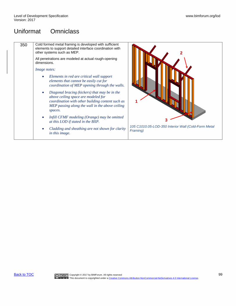
Level of Development Specification Version: 2017
www.bimforum.org/lod
Uniformat Omniclass
Back to TOC Copyright © 2017 by BIMForum. All rights reserved 99
This document is copyrighted under a Creative Commons Attribution-NonCommercial-NoDerivatives 4.0 International License.
350 Cold formed metal framing is developed with sufficient elements to support detailed interface coordination with other systems such as MEP.
All penetrations are modeled at actual rough-opening dimensions.
Image notes:
• Elements in red are critical wall support
elements that cannot be easily cut for
coordination of MEP opening through the walls.
• Diagonal bracing (kickers) that may be in the
above ceiling space are modeled for
coordination with other building content such as
MEP passing along the wall in the above ceiling
spaces.
• Infill CFMF modeling (Orange) may be omitted
at this LOD if stated in the BXP.
• Cladding and sheathing are not shown for clarity
in this image.
2
1
3
105 C1010.05-LOD-350 Interior Wall (Cold-Form Metal Framing)
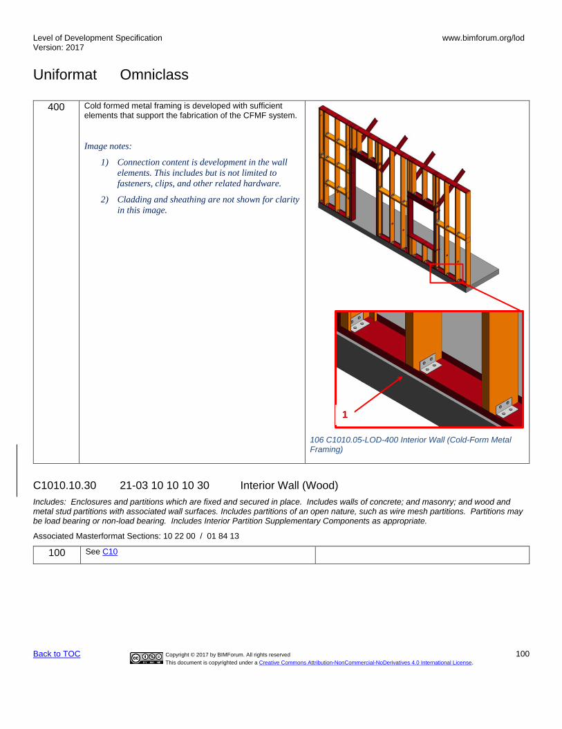
Level of Development Specification Version: 2017
www.bimforum.org/lod
Uniformat Omniclass
Back to TOC Copyright © 2017 by BIMForum. All rights reserved 100
This document is copyrighted under a Creative Commons Attribution-NonCommercial-NoDerivatives 4.0 International License.
400 Cold formed metal framing is developed with sufficient elements that support the fabrication of the CFMF system.
Image notes:
1) Connection content is development in the wall
elements. This includes but is not limited to
fasteners, clips, and other related hardware.
2) Cladding and sheathing are not shown for clarity
in this image.
106 C1010.05-LOD-400 Interior Wall (Cold-Form Metal Framing)
C1010.10.30 21-03 10 10 10 30 Interior Wall (Wood)
Includes: Enclosures and partitions which are fixed and secured in place. Includes walls of concrete; and masonry; and wood and metal stud partitions with associated wall surfaces. Includes partitions of an open nature, such as wire mesh partitions. Partitions may be load bearing or non-load bearing. Includes Interior Partition Supplementary Components as appropriate.
Associated Masterformat Sections: 10 22 00 / 01 84 13
100 See C10
1

Level of Development Specification Version: 2017
www.bimforum.org/lod
Uniformat Omniclass
Back to TOC Copyright © 2017 by BIMForum. All rights reserved 101
This document is copyrighted under a Creative Commons Attribution-NonCommercial-NoDerivatives 4.0 International License.
200 See C1010
300 See C1010
108 C1010.06-LOD-300 Interior Wall (Wood)
107 C1010.06-LOD-200 Interior Wall (Wood)

Level of Development Specification Version: 2017
www.bimforum.org/lod
Uniformat Omniclass
Back to TOC Copyright © 2017 by BIMForum. All rights reserved 102
This document is copyrighted under a Creative Commons Attribution-NonCommercial-NoDerivatives 4.0 International License.
350 Wood framing is developed with sufficient elements to support detailed interface coordination with other systems such as MEP.
All penetrations are modeled at actual rough-opening dimensions.
Image notes:
1) Elements in red are critical wall support elements
that cannot be easily cut for coordination of MEP
opening through the walls.
2) Infill wood framing modeling may be omitted at this
LOD if stated in the BXP.
3) Cladding and sheathing are not shown for clarity in
this image.
400 Wood framing is developed with sufficient elements that support the fabrication of the wood framing system.
Openings and penetrations through studs are modeled.
Image notes:
1) Connection content is development in the wall
elements. This includes but is not limited to
fasteners, anchor rods, and other related hardware.
2) Cladding and sheathing are not shown for clarity in
this image.
110 C1010.06-LOD-400 Interior Wall (Wood)
2
1
1
109 C1010.06-LOD-350 Interior Wall (Wood)

Level of Development Specification Version: 2017
www.bimforum.org/lod
Uniformat Omniclass
Back to TOC Copyright © 2017 by BIMForum. All rights reserved 103
This document is copyrighted under a Creative Commons Attribution-NonCommercial-NoDerivatives 4.0 International License.
C1010.20 21-03 10 10 20 Interior Glazed Partitions Includes: Partitions primarily composed of glazed elements that may be fabricated or field constructed. Includes Interior Partition Supplementary Components as appropriate.
Associated Masterformat Sections: 08 43 00
100 See C10
200 See C1010
300 Specified location and orientation of face of glass.
Nominal face dimensions and thickness of glazing.
Structural support systems of wall to be modeled.
Spacing, location, size and orientation of mullions.
Operable components defined (doors) and included in model.
350 • Mullion shapes and geometry defined.
• Actual anchorage layouts and types defined.
• Actual panel dimensions (including seating).
400 • Complete mullion extrusion profiles.
• Interface details between wall systems (within) and wall and support systems.
C1010.40 21-03 10 10 40 Interior Demountable Partitions
Associated Masterformat Sections: 10 22 19 / 01 84 13 / 10 22 19.13 / 10 22 19.23 / 10 22 19.33 10 22 19.43 / 10 22 19.53
100 See C10
200 See C1010
300 See C1010.10
350 See C1010.10 – also include hardware, accessories, and support structure.
400 See C1010.10
C1010.50 21-03 10 10 50 Interior Operable Partitions Includes: Track-supported, operable panels and partitions, top hung and floor supported, and manually and power operated. Includes auditorium partitions and dividers. Includes overhead supports.
Associated Masterformat Sections: 01 84 13 / 01 84 13 / 10 22 33 / 10 22 36 / 10 22 39 10 22 43
100 See C10
200 See C1010

Level of Development Specification Version: 2017
www.bimforum.org/lod
Uniformat Omniclass
Back to TOC Copyright © 2017 by BIMForum. All rights reserved 104
This document is copyrighted under a Creative Commons Attribution-NonCommercial-NoDerivatives 4.0 International License.
300 Operable partition system modeled to include spatial requirements for open/storage position and closed position.
Spatial requirements for structure (overhead or below) to be modeled.
350 Major support elements (overhead or below)
Mechanical connections
400 All assembly components including tracks, panels, hardware and supports.
C1010.70 21-03 10 10 70 Interior Screens Portable and open dividers.
Associated Masterformat Sections: 10 22 23 / 10 82 23
[See C1010.10]
C1010.90 21-03 10 10 90 Interior Partitions Supplementary Components Sound isolation components, firestopping, and expansion control to be included with interior partition elements above as appropriate.
These components are typically modeled as part of other assemblies listed in the tables above. Do not assign this Uniformat classification unless a supplementary component is modeled independently of another assembly.
Associated Masterformat Sections: 13 48 00 / 09 81 00 / 07 84 00 / 07 95 00
C1020 21-03 10 20 Interior Windows Includes: Interior fixed or operable windows used singly and in multiples. Includes Interior Window Supplementary Components as appropriate. Includes metal, wood, plastic, and composite window units.
Associated Masterformat Sections: 08 50 00 / 01 84 13
100 See C10
200 Windows approximate in terms of location, size, count and type. Units are modeled as a simple, monolithic component; or represented with simplified frame and glazing.
Nominal unit size is provided.
C1020.10 21-03 10 20 10 Interior Operating Windows Includes: Interior fixed or operable windows used singly and in multiples. Includes Interior Window Supplementary Components as appropriate. Includes metal, wood, plastic, and composite window units.
Associated Masterformat Sections: 08 50 00
100 See C10
200 See C1020

Level of Development Specification Version: 2017
www.bimforum.org/lod
Uniformat Omniclass
Back to TOC Copyright © 2017 by BIMForum. All rights reserved 105
This document is copyrighted under a Creative Commons Attribution-NonCommercial-NoDerivatives 4.0 International License.
300 Units are modeled based on specified location and nominal size. Outer geometry of window frame elements and glazing modeled.
Operation is indicated.
Non-graphic information associated with model element:
Aesthetic characteristics (finishes, glass types) Performance characteristics (i.e. U-value, wind loading, blast resistance, structural, air, thermal, water, sound) Functionality of the window (fixed, casement, double/single hung, awning/project out, pivot, sliding)
350 Attachment method of window to structure
Embed geometry
400 Frame profiles
Glazing sub-components (gaskets)
Attachment components
C1020.20 21-03 10 20 20 Interior Fixed Windows
Includes: Interior fixed or operable windows used singly and in multiples. Includes Interior Window Supplementary Components as appropriate. Includes metal, wood, plastic, and composite window units.
Associated Masterformat Sections: 08 50 00
C1020.50 21-03 10 20 50 Interior Special Function Windows
Includes interior windows with special characteristics for a special function.
Associated Masterformat Sections: 08 56 00 / 08 56 19 / 08 56 46 / 08 56 49 / 08 88 49 / 08 56 53 / 08 88 53 / 08 88 56 / 08 56 63 / 08 56 73
C1020.90 21-03 10 20 90 Interior Window Supplementary Components Includes: Frames, sills, operating hardware, glazing to be included with interior window elements above as appropriate.
These components are typically modeled as part of other assemblies listed in the tables above. Do not assign this Uniformat classification unless a supplementary component is modeled independently of another assembly.
Associated Masterformat Sections: 08 75 00 / 08 80 00
C1030 21-03 10 30 Interior Doors Includes: Interior door assemblies. Includes metal doors and frames, wood doors and frames, plastic doors, and composite doors. Includes Interior Door Supplementary Components as appropriate.
Associated Masterformat Sections: 08 10 00 / 01 84 13
100 See C10
200 Units are modeled as a simple, monolithic component; or represented with simple frame and panel.
Nominal unit size is provided.

Level of Development Specification Version: 2017
www.bimforum.org/lod
Uniformat Omniclass
Back to TOC Copyright © 2017 by BIMForum. All rights reserved 106
This document is copyrighted under a Creative Commons Attribution-NonCommercial-NoDerivatives 4.0 International License.
C1030.10 21-03 10 30 10 Interior Swinging Doors Includes: Interior door assemblies. Includes metal doors and frames, wood doors and frames, plastic doors, and composite doors. Includes Interior Door Supplementary Components as appropriate.
Associated Masterformat Sections: 08 10 00
100 See C10
200 See C1030
300 Door assemblies modeled by type to include the following:
• Specific door panels and frames (if applicable).
• Operation is specified
350 Major framing elements are modeled at jambs and head in containing wall.
Operation or mechanism enclosures are modeled, if applicable.
400 Actual frame/mullion extrusions.
Actual panel size dimensions.
All connections and interfaces modeled including brackets, supports, sealants, and thresholds.
C1030.20 21-03 10 30 20 Interior Entrance Doors Includes: Exterior personnel door assemblies at interior main entrances. Includes automatic, revolving, balanced, and other special operating entrance doors, and sliding storefront wall systems. Includes Interior Door Supplementary Components as appropriate when not part of storefront system.
Associated Masterformat Sections: 08 42 00 / 08 42 26 / 08 42 29 / 08 42 33 / 08 42 36 08 43 29
[See B2050.10]
C1030.25 21-03 10 30 25 Interior Sliding Doors
Associated Masterformat Sections: 08 11 73 / 08 32 00
[See C1030.10]
C1030.30 21-03 10 30 30 Interior Folding Doors
Associated Masterformat Sections: 08 35 13
[See C1030.10]
C1030.40 21-03 10 30 40 Interior Coiling Doors
Associated Masterformat Sections: 08 33 00 / 08 33 13
100 See C10
200 See C1030
300 Coiling door assemblies modeled by type to include the following:
• Door panels with nominal dimensions.
Level of Development Specification Version: 2017
www.bimforum.org/lod
Uniformat Omniclass
Back to TOC Copyright © 2017 by BIMForum. All rights reserved 107
This document is copyrighted under a Creative Commons Attribution-NonCommercial-NoDerivatives 4.0 International License.
• Frames with nominal dimensions.
• Hardware set functionality and types included in non-graphic information.
• Clearance zones for operation of overhead doors are modeled or accommodated by model checking software.
• Enclosures and motor housings are modeled with overall nominal dimensions.
350 Major framing elements in wall are modeled at jambs and head.
Other major structural support elements are modeled.
400 All connections and interfaces modeled including brackets, supports, sealants, and thresholds.
C1030.50 21-03 10 30 50 Interior Panel Doors
Includes: Interior large opening doors constructed of panels that move.
Associated Masterformat Sections: 08 36 00 / 08 36 13 / 08 36 16 / 08 36 19 / 08 36 23
[See C1030.40]
C1030.70 21-03 10 30 70 Interior Special Function Doors Includes: Interior door assemblies for a variety of special functions and applications involving a variety of operating methods. Includes Interior Door Supplementary Components as appropriate.
Associated Masterformat Sections: 08 30 00. / 08 34 13 / 08 34 19 / 08 34 33 / 08 34 36 08 34 46 / 08 34 49 / 08 88 49 / 08 34 53 / 08 42 33.13 / 08 88 53 / 08 88 56 / 08 34 59 08 34 63 / 08 34 73 / 08 38 00 / 08 39 00
[See C1030.40]
C1030.80 21-03 10 30 80 Interior Access Doors and Panels Includes: Doors and panels in walls, ceilings, and floors to provide access to concealed spaces. Includes frames and hardware.
Associated Masterformat Sections: 08 31 00
[See C1030.40]
C1030.90 21-03 10 30 90 Interior Door Supplementary Components Includes: Frames, hardware, glazing, and louvers that are part of door to be included with interior door elements above as appropriate.
These components are typically modeled as part of other assemblies listed in the tables above. Do not assign this Uniformat classification unless a supplementary component is modeled independently of another assembly.
Associated Masterformat Sections: 08 10 00 / 08 30 00 / 08 71 00 / 08 80 00 / 08 91 26

Level of Development Specification Version: 2017
www.bimforum.org/lod
Uniformat Omniclass
Back to TOC Copyright © 2017 by BIMForum. All rights reserved 108
This document is copyrighted under a Creative Commons Attribution-NonCommercial-NoDerivatives 4.0 International License.
C1040 21-03 10 40 Interior Grilles and Gates Includes: Interior operable grilles and gates Includes frames and hardware.
100 See C10
200 See C1030
C1040.10 21-03 10 40 10 Interior Grilles Associated Masterformat Sections: 08 11 74 / 08 33 00 / 08 35 16
100 See C10
200 See C1030
300 Grille assemblies modeled by type to include the following:
• Nominal size of unit.
• Required openness provided as non-graphic information.
• Operation is specified graphically.
350 Major framing elements are modeled at jambs and head.
400 All connections and interfaces modeled including brackets, supports, sealants, and thresholds.
C1040.50 21-03 10 40 50 Interior Gates
Includes: Interior devices of solid or open construction, usually hinged, to provide moveable barrier for access through partition or other divider. Includes hardware, accessories, and finishing. Associated Masterformat Sections: 08 34 56 / 10 22 16
[See C1040.10]
C1060 21-03 10 60 Raised Floor Construction
Associated Masterformat Sections: 01 84 13 / 01 84 13 / 01 84 13 / 01 84 13 / 01 84 13 01 84 13 / 01 84 13 / 01 84 13 / 01 84 13
100 See C10
200 Generic assembly that contains spatial allowance for support system and flooring material.
C1060.10 21-03 10 60 10 Access Flooring
Includes: Free-standing, elevated accessible floor assembly forming an underfloor cavity that may be used for utility or other purposes. Associated Masterformat Sections: 09 69 00

Level of Development Specification Version: 2017
www.bimforum.org/lod
Uniformat Omniclass
Back to TOC Copyright © 2017 by BIMForum. All rights reserved 109
This document is copyrighted under a Creative Commons Attribution-NonCommercial-NoDerivatives 4.0 International License.
100 See C10
200 See C1060
300 Overall flooring assembly modeled by type to specified thickness/depth.
Major openings such as shafts are modeled.
350 Individual layers of assembly are modeled separately.
All openings and penetrations are modeled.
Expansion joints are modeled indicating specific width.
Pedestals are modeled and located properly, if applicable.
400 All assembly components are modeled including frame, floor tiles, pedestals, and cross bracing.
C1060.30 21-03 10 60 30 Platform/Stage Floors
Includes: Fixed construction of raised floor for platforms or stages. [See C1060.10]
C1070 21-03 10 70 Suspended Ceiling Construction Includes: Ceiling Suspension Components.
Associated Masterformat Sections: 01 84 13 / 01 84 13
100 Ceiling construction is represented in other composite objects such as floors or rooms; or, schematic model elements that are not distinguishable by type or material.
Assembly depth/thickness and locations still flexible.
200 Generic assemblies indicative of overall scope and approximate thickness/system depth of suspended ceiling.
C1070.10 21-03 10 70 10 Acoustical Suspended Ceilings Includes: Suspended tiles and panels with specific characteristics for acoustical purposes.
Associated Masterformat Sections: 09 51 00 / 09 81 00
100 See C1070
200 See C1070
300 Overall assembly modeled to specific system thickness including structural backing.
Location of expansion or control joints indicated, but not modeled.

Level of Development Specification Version: 2017
www.bimforum.org/lod
Uniformat Omniclass
Back to TOC Copyright © 2017 by BIMForum. All rights reserved 110
This document is copyrighted under a Creative Commons Attribution-NonCommercial-NoDerivatives 4.0 International License.
Ceiling grid is shown as linework.
350 Ceiling suspension grid is modeled.
Structural backing members including bracing/lateral framing/kickers are modeled.
Expansion or control joints are modeled to indicate specific width.
400 All assembly components are modeled including tees, hangers, support structure, and tiles.
C1070.20 21-03 10 70 20 Suspended Plaster and Gypsum Board Ceilings Includes: Suspended assemblies with plaster and gypsum board surfaces.
Associated Masterformat Sections: 09 20 00 / 09 22 26 / 09 81 00
100 See C1070
200 See C1070
300 Overall assembly modeled to specific system thickness including framing.
Bulkheads
Major penetrations are modeled.
350 Major bracing elements such as kickers are modeled.
400 All assembly components including furring channels, hangers, lath, plaster coats, and gypsum boards.
C1070.50 21-03 10 70 50 Specialty Suspended Ceilings Includes: Suspended specialty ceiling panels, units, and materials manufactured as finished
Associated Masterformat Sections: 09 54 00 / 09 56 00
[See C1070.10 or C1070.20]
C1070.70 21-03 10 70 70 Special Function Suspended Ceilings Includes: Suspended ceiling assemblies with an additional special function including integrated ceiling assemblies.
Associated Masterformat Sections: 09 57 00 / 09 57 53 / 09 58 00
[See C1070.10 or C1070.20]
C1070.90 21-03 10 70 90 Ceiling Suspension Components Includes: Hangers and framing to suspend ceiling and sound isolation components to be included with suspended ceiling construction elements above as appropriate.
These components are typically modeled as part of other assemblies listed in the tables above. Do not assign this Uniformat classification unless a supplementary component is modeled independently of another assembly.
Associated Masterformat Sections: 13 48 00
Level of Development Specification Version: 2017
www.bimforum.org/lod
Uniformat Omniclass
Back to TOC Copyright © 2017 by BIMForum. All rights reserved 111
This document is copyrighted under a Creative Commons Attribution-NonCommercial-NoDerivatives 4.0 International License.
C1090 21-03 10 90 Interior Specialties 100 See C10
200 Generic model elements with approximate nominal size.
Placement and quantity remains flexible.
C1090.10 21-03 10 90 10 Interior Railings and Handrails Includes: Complete interior railing assemblies of various types including glazed railings.
Associated Masterformat Sections: 01 84 00 / 01 84 00 / 01 84 00 / 01 84 00 / 05 52 00 05 73 00 / 06 43 16 / 06 63 00 / 06 81 00
100 See C10
200 Generic model element representing approximate overall height and location of railing/handrail.
300 Railing/handrail systems modeled by type to include:
• All horizontal rails
• All vertical posts/balusters
350 Mounting/attachment components
400 All assembly components including fasteners and supports.
C1090.15 21-03 10 90 15 Interior Louvers Includes: Interior louvers, and other items for ventilation which are not an integral part of the mechanical system. Includes operable and stationary louvers.
Associated Masterformat Sections: 08 91 00 / 01 84 00
100 See C10
200 Generic model element that is indicative of approximate area and location of louver.
300 Louver assembly modeled by type, indicative of area and location of intended louver/vent.
Accurate frame and blade boundary areas
Opening for louver is cut from host wall.
350 Rough opening is modeled in containing wall.
Major framing elements are modeled at jambs and head.
Connection points are modeled.
400 All connections and interfaces modeled including brackets, supports, and sealants.

Level of Development Specification Version: 2017
www.bimforum.org/lod
Uniformat Omniclass
Back to TOC Copyright © 2017 by BIMForum. All rights reserved 112
This document is copyrighted under a Creative Commons Attribution-NonCommercial-NoDerivatives 4.0 International License.
C1090.20 21-03 10 90 20 Information Specialties Includes: Visual display units, display cases, directories, interior signage, telephone specialties, and informational kiosks.
Associated Masterformat Sections: 10 10 00 / 10 11 00 / 10 11 13 / 10 11 16 / 10 11 23 10 11 33 / 10 11 36 / 10 11 39 / 10 11 43 / 10 11 46 / 10 12 00 / 10 13 00 / 10 14 00 10 17 00 / 10 18 00
[See Fundamental LOD Definitions]
C1090.25 21-03 10 90 25 Compartments and Cubicles Includes: Manufactured compartments and cubicles for specific purposes. Includes toilet compartments, shower stalls, etc.
Associated Masterformat Sections: 10 21 00 / 10 21 13 / 10 21 16 / 10 21 23 / 10 28 19
[See Fundamental LOD Definitions]
C1090.30 21-03 10 90 30 Service Walls Includes: Wall assemblies and wall-mounted units incorporating services.
Associated Masterformat Sections: 10 25 00 / 10 25 13 / 10 25 16
[See C1010.10]
C1090.35 21-03 10 90 35 Wall and Door Protection Includes: Manufactured protective devices for walls and doors. Includes corner guards, bumper guards, and protective wall covering.
Associated Masterformat Sections: 10 26 00 / 10 26 13 / 10 26 16 / 10 26 23 / 10 26 33
[See Fundamental LOD Definitions]
C1090.40 21-03 10 90 40 Toilet, Bath and Laundry Accessories Includes: Manufactured items for use in conjunction with toilets, baths, and laundries.
Associated Masterformat Sections: 10 28 00 / 10 28 13 / 10 28 16 / 10 28 23
[See Fundamental LOD Definitions]
C1090.45 21-03 10 90 45 Interior Gas Lighting Associated Masterformat Sections: 10 84 16
[See Fundamental LOD Definitions]
C1090.50 21-03 10 90 50 Fireplaces and Stoves
Includes: Masonry fireplaces and manufactured and fabricated fireplaces, stoves, chimneys, dampers, and specialties for use in construction of fireplaces and stove units. Associated Masterformat Sections: 10 30 00 / 04 50 00 / 04 57 00 / 10 31 00 / 10 31 13 10 32 00 / 10 35 00
[See Fundamental LOD Definitions]
Level of Development Specification Version: 2017
www.bimforum.org/lod
Uniformat Omniclass
Back to TOC Copyright © 2017 by BIMForum. All rights reserved 113
This document is copyrighted under a Creative Commons Attribution-NonCommercial-NoDerivatives 4.0 International License.
C1090.60 21-03 10 90 60 Safety Specialties
Includes: Accessories that provide emergency aid. Associated Masterformat Sections: 10 40 00 / 10 41 00 / 10 43 00
[See Fundamental LOD Definitions]
C1090.70 21-03 10 90 70 Storage Specialties
Includes: Lockers, postal specialties, storage specialties, and wardrobe and closet specialties. Associated Masterformat Sections: 10 50 00 / 10 51 00 / 10 51 53 / 10 55 00 / 10 55 23 / 10 55 91 / 10 56 00 / 10 56 29 / 10 56 33 / 10 57 00 / 10 57 13 / 10 57 33
[See Fundamental LOD Definitions]
C1090.90 21-03 10 90 90 Other Interior Specialties
Includes: Pest control devices, flags and banners, security mirrors and domes, and scales. Associated Masterformat Sections: 10 80 00 / 10 81 00 / 10 81 16 / 10 81 19 / 10 83 00 / 08 83 00 / 10 86 00 / 10 88 00
[See Fundamental LOD Definitions]
C20 21-03 20 Interior Finishes Associated Masterformat Sections: 01 84 19
100 Non-graphic information attached to model elements providing assumptions about proposed finish materials. See Part II
C2010 21-03 20 10 Wall Finishes Includes: Wall finishes applied over solid substrates. Includes Wall Finish Supplementary Components as appropriate.
Associated Masterformat Sections: 09 70 00 / 01 84 19 / 01 84 19 / 01 84 19 / 01 84 19 / 01 84
100 See C20
200 Generic materials other than sheet goods and coatings by type (e.g. tile or paneling), approximate thickness and scope in elevation.
300 Materials are modeled based on specific types (e.g. Tile type CT-1).
Thickness and scope of finishes other than sheet goods and coatings are accurately modeled.

Level of Development Specification Version: 2017
www.bimforum.org/lod
Uniformat Omniclass
Back to TOC Copyright © 2017 by BIMForum. All rights reserved 114
This document is copyrighted under a Creative Commons Attribution-NonCommercial-NoDerivatives 4.0 International License.
Sheet goods and coatings may be specified in Part II related to interior partitions.
350 Additional non-graphic information to include:
• Manufacturer
• Model
400 Pattern layouts
Expansion/control joints
Edges
C2010.10 21-03 20 10 10 Tile Wall Finish Includes: Manufactured surfacing units of impervious, vitreous, semi-vitreous, and non-vitreous materials; glazed, unglazed, conductive, and textured surfaces.
Associated Masterformat Sections: 09 30 00
[See C2010]
C2010.20 21-03 20 10 20 Wall Paneling Includes: Covering or cladding of interior walls with paneling. Includes associated furring, fastening, and trim.
Associated Masterformat Sections: 06 42 00 / 06 25 00 / 06 26 00 / 06 64 00 / 06 83 00
[See C2010]
C2010.30 21-03 20 10 30 Wall Coverings Includes: Wall coverings applied over solid substrates. Includes vinyl-coated fabric, vinyl and cork wall coverings; wall papers; and flexible wood sheets.
Associated Masterformat Sections: 09 72 00 / 09 74 00
[See C2010]
C2010.35 21-03 20 10 35 Wall Carpeting Includes: Wall carpet materials and accessories.
Associated Masterformat Sections: 09 73 00
C2010.50 21-03 20 10 50 Stone Facing Includes: Natural stone applied as an interior veneer surface.
Associated Masterformat Sections: 09 75 00
[See C2010]
C2010.60 21-03 20 10 60 Special Wall Surfacing Includes: Manufactured decorative interior wall surface products including plastic blocks.
Associated Masterformat Sections: 09 77 00 / 09 77 13 / 09 77 23 / 09 76 00
[See C2010]

Level of Development Specification Version: 2017
www.bimforum.org/lod
Uniformat Omniclass
Back to TOC Copyright © 2017 by BIMForum. All rights reserved 115
This document is copyrighted under a Creative Commons Attribution-NonCommercial-NoDerivatives 4.0 International License.
C2010.70 21-03 20 10 70 Wall Painting and Coating Includes: Interior painting and coating with transparent and opaque finishes. Includes stains, varnishes, lacquers, primers, fillers, paint removers, and waxes, and preparation of surfaces.
Associated Masterformat Sections: 09 90 00
[See C2010]
C2010.80 21-03 20 10 80 Acoustical Wall Treatment Includes: Sound absorbing, reflecting, and diffusing wall units, and accessories.
Associated Masterformat Sections: 09 83 13 / 09 84 00 / 09 84 33
[See C2010]
C2010.90 21-03 20 10 90 Wall Finish Supplementary Components Includes: Furring to be included with wall finish elements above as appropriate.
Associated Masterformat Sections: 06 10 00 / 09 22 13
[See C1010]
C2020 21-03 20 20 Interior Fabrications Includes: Interior fabrications of a variety of materials formed to various profiles for a variety of purposes including column covers.
Associated Masterformat Sections: 03 49 00 / 05 50 00 / 05 58 13 / 05 70 00 / 06 44 00 / 06 60 00 / 06 61 00 / 06 80 00 / 09 27 00
[See Fundamental LOD Definitions]
C2030 21-03 20 30 Flooring Includes: Flooring Supplementary Components as appropriate.
Associated Masterformat Sections: 09 60 00 / 01 84 19
[See C2010]

Level of Development Specification Version: 2017
www.bimforum.org/lod
Uniformat Omniclass
Back to TOC Copyright © 2017 by BIMForum. All rights reserved 116
This document is copyrighted under a Creative Commons Attribution-NonCommercial-NoDerivatives 4.0 International License.
C2030.10 21-03 20 30 10 Flooring Treatment TBD
C2030.20 21-03 20 30 20 Tile Flooring TBD
C2030.30 21-03 20 30 30 Specialty Flooring TBD
C2030.40 21-03 20 30 40 Masonry Flooring TBD
C2030.45 21-03 20 30 45 Wood Flooring TBD
C2030.50 21-03 20 30 50 Resilient Flooring TBD
C2030.60 21-03 20 30 60 Terrazzo Flooring TBD
C2030.70 21-03 20 30 70 Fluid-Applied Flooring TBD
C2030.75 21-03 20 30 75 Carpeting TBD
C2030.80 21-03 20 30 80 Athletic Flooring TBD
C2030.85 21-03 20 30 85 Entrance Flooring TBD
C2030.90 21-03 20 30 90 Floor Supplementary Components TBD
C2040 21-03 20 40 Stair Finishes Includes: Stair tread, riser, and landing finish of various materials.
Associated Masterformat Sections: 01 84 19
[See C2010]
Level of Development Specification Version: 2017
www.bimforum.org/lod
Uniformat Omniclass
Back to TOC Copyright © 2017 by BIMForum. All rights reserved 117
This document is copyrighted under a Creative Commons Attribution-NonCommercial-NoDerivatives 4.0 International License.
C2040.20 21-03 20 40 20 Tile Stair Finish TBD
C2040.40 21-03 20 40 40 Masonry Stair Finish 09 63 00 TBD
C2040.45 21-03 20 40 45 Wood Stair Finish 09 64 00 TBD
C2040.50 21-03 20 40 50 Resilient Stair Finish 09 65 00 TBD
C2040.60 21-03 20 40 60 Terrazzo Stair Finish 09 66 00 TBD
C2040.75 21-03 20 40 75 Carpeted Stair Finish 09 68 00 TBD
C2050 21-03 20 50 Ceiling Finishes Includes: Finishes applied to interior ceiling substrates. Ceiling finishes may be applied to suspended ceiling construction. Includes Ceiling Finish Supplementary Components as appropriate.
Associated Masterformat Sections: 09 50 00 / 01 84 19
C2050.10 21-03 20 50 10 Plaster and Gypsum Board Finish TBD
C2050.20 21-03 20 50 20 Ceiling Paneling TBD
C2050.70 21-03 20 50 70 Ceiling Painting and Coating TBD
C2050.80 21-03 20 50 80 Acoustical Ceiling Treatment TBD
C2050.90 21-03 20 50 90 Ceiling Finish Supplementary Components TBD

Level of Development Specification Version: 2017
www.bimforum.org/lod
Uniformat Omniclass
Back to TOC Copyright © 2017 by BIMForum. All rights reserved 118
This document is copyrighted under a Creative Commons Attribution-NonCommercial-NoDerivatives 4.0 International License.
D 21-04 00 00 SERVICES Associated Masterformat Sections: 01 86 00
D10 21-04 10 Conveying Associated Masterformat Sections: 01 85 00 / 14 00 00
100 Schematic model elements that are not distinguishable by type or material.
Component sizes and locations still flexible.
D1010 21-04 10 10 Vertical Conveying Systems Associated Masterformat Sections:
100 See D10
200 Generic representation of the system envelope, including critical path of travel zones.

Level of Development Specification Version: 2017
www.bimforum.org/lod
Uniformat Omniclass
Back to TOC Copyright © 2017 by BIMForum. All rights reserved 119
This document is copyrighted under a Creative Commons Attribution-NonCommercial-NoDerivatives 4.0 International License.
D1010.10 21-04 10 10 10 Elevators Includes: Passenger and freight elevators of all types, including cars, enclosures, controls, safety equipment, hoist way equipment, and elevator machinery. Includes associated metal fabrications including pit ladders.
Associated Masterformat Sections: 01 85 00 / 14 20 00 / 14 21 13 / 14 21 23 / 14 21 33 14 21 43 / 14 24 13 / 14 24 23 / 14 24 33 / 14 24 43 / 14 26 00 / 14 27 00 / 14 28 00
100 See D10
200 See D1010

Level of Development Specification Version: 2017
www.bimforum.org/lod
Uniformat Omniclass
Back to TOC Copyright © 2017 by BIMForum. All rights reserved 120
This document is copyrighted under a Creative Commons Attribution-NonCommercial-NoDerivatives 4.0 International License.
300 Specific system elements modeled by type, including all path of travel zones.
Pits and/or control rooms and associated equipment to be modeled if applicable.
Major structural support elements modeled.
Connections to mechanical or electrical services.
350 Sizing adjusted to the actual manufacturer specifications.
Guiding tracks/rails
Service/access zones

Level of Development Specification Version: 2017
www.bimforum.org/lod
Uniformat Omniclass
Back to TOC Copyright © 2017 by BIMForum. All rights reserved 121
This document is copyrighted under a Creative Commons Attribution-NonCommercial-NoDerivatives 4.0 International License.
400 All connections, supports, framing, and other supplementary components.
D1010.20 21-04 10 10 20 Lifts Includes: Vertical or inclined lifts and related equipment for a variety of purposes. Sidewalk lifts include doors.
Associated Masterformat Sections: 01 85 00 / 14 40 00 / 14 41 00 / 14 42 00 / 14 43 00 14 43 13 / 14 43 16 / 14 44 00 / 14 45 00
[See D1010.10]
D1010.30 21-04 10 10 30 Escalators Includes: Passenger conveying systems composed of moving treads installed in inclined position including associated components, hardware, controls, safety equipment, and related items.
Associated Masterformat Sections: 01 85 00 / 14 31 00
[See D1010.10]
D1010.50 21-04 10 10 50 Dumbwaiters Includes: Packaged and field assembled, motorized and hand- operated dumbwaiters including associated components for book lifts, cart lifts, and other applications. Systems include associated components, hardware, controls, and safety equipment.
Associated Masterformat Sections: 01 85 00 / 14 10 00

Level of Development Specification Version: 2017
www.bimforum.org/lod
Uniformat Omniclass
Back to TOC Copyright © 2017 by BIMForum. All rights reserved 122
This document is copyrighted under a Creative Commons Attribution-NonCommercial-NoDerivatives 4.0 International License.
[See D1010.10]
D1010.60 21-04 10 10 60 Moving Ramps Includes: Passenger conveying systems composed of moving belts installed in inclined position including associated components, hardware, controls, safety equipment, and related items.
Associated Masterformat Sections: 01 85 00 / 14 33 00
[See D1010.10]
D1030 21-04 10 30 Horizontal Conveying Associated Masterformat Sections: 01 85 00
[See D1010.10]
D1030.10 21-04 10 30 10 Moving Walks Includes: Passenger conveying systems composed of moving belts installed in horizontal position including associated components, hardware, controls, safety equipment, and related items.
Associated Masterformat Sections: 01 85 00 / 14 32 00
[See D1010.10]
D1030.30 21-04 10 30 30 Turntables Includes: Structural turntables for various applications.
Associated Masterformat Sections: 01 85 00 / 14 70 00 / 14 71 00 / 14 71 11 / 14 72 00 14 72 25 / 14 73 00 / 14 73 59 / 14 74 00 / 14 74 61
[See D1010.10]
D1030.50 21-04 10 30 50 Passenger Loading Bridges Includes: Operating bridges for loading and unloading of passengers to and from aircraft and ships.
Associated Masterformat Sections: 01 85 00 / 34 77 13
[See D1010.10]
D1030.70 21-04 10 30 70 People Movers Includes: Single rail vehicles suspended from or straddle the guideway. Includes associated track, equipment, controls, and accessories. Includes: Steep cable railways in which ascending cars counterbalance descending cars. Includes associated track, cable. Includes: Steep slope transportation system utilizing moving cable. Includes associated cable, support structures, equipment, controls, and accessories.
Associated Masterformat Sections: 01 85 00 / 34 12 00 / 34 13 00 / 34 14 00
[See D1010.10]
D1050 21-04 10 50 Material Handling Associated Masterformat Sections: 01 85 00

Level of Development Specification Version: 2017
www.bimforum.org/lod
Uniformat Omniclass
Back to TOC Copyright © 2017 by BIMForum. All rights reserved 123
This document is copyrighted under a Creative Commons Attribution-NonCommercial-NoDerivatives 4.0 International License.
100 See D10
200 Generic representation of the material handling system envelope, including critical path of travel zones.
D1050.10 21-04 10 50 10 Cranes Includes: Hoisting towers, cranes, crane rails, and related accessories.
Associated Masterformat Sections: 41 22 13
100 See D10
200 See D1050
300 Specific system elements modeled by type, including all path of travel/boom swing zones.
Lay-down/pick-up zones are modeled.
Major structural support elements modeled.
Connections to mechanical or electrical services.
350 Sizing adjusted to the actual manufacturer specifications.
Guiding tracks/rails
Service/access zones
400 All connections, supports, framing, and other supplementary components.
D1050.20 21-04 10 50 20 Hoists Includes: Manual and motor operated hoists and related accessories.
Associated Masterformat Sections: 41 22 23
[See D1050.10]
D1050.30 21-04 10 50 30 Derricks Includes: Manual and motor operated derricks and related accessories.
Associated Masterformat Sections: 41 22 33
[See D1050.10]
D1050.40 21-04 10 50 40 Conveyors Includes: Automatic guided vehicles, conveyors, diverters, and chutes. Includes controls and accessories.
Associated Masterformat Sections: 41 21 00
[See D1050.10]
D1050.50 21-04 10 50 50 Baggage Handling Equipment Includes: Operating equipment for handling, scanning, and weighing of baggage at terminals. Includes controls and accessories.
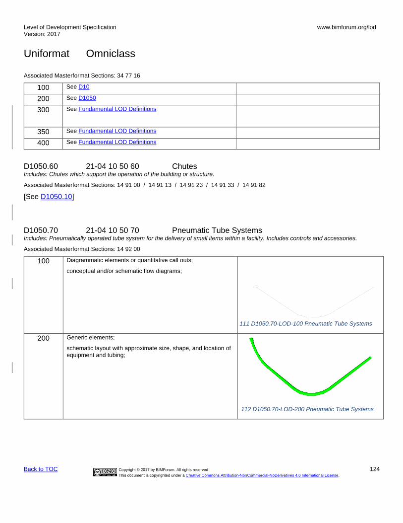
Level of Development Specification Version: 2017
www.bimforum.org/lod
Uniformat Omniclass
Back to TOC Copyright © 2017 by BIMForum. All rights reserved 124
This document is copyrighted under a Creative Commons Attribution-NonCommercial-NoDerivatives 4.0 International License.
Associated Masterformat Sections: 34 77 16
100 See D10
200 See D1050
300 See Fundamental LOD Definitions
350 See Fundamental LOD Definitions
400 See Fundamental LOD Definitions
D1050.60 21-04 10 50 60 Chutes Includes: Chutes which support the operation of the building or structure.
Associated Masterformat Sections: 14 91 00 / 14 91 13 / 14 91 23 / 14 91 33 / 14 91 82
[See D1050.10]
D1050.70 21-04 10 50 70 Pneumatic Tube Systems Includes: Pneumatically operated tube system for the delivery of small items within a facility. Includes controls and accessories.
Associated Masterformat Sections: 14 92 00
100 Diagrammatic elements or quantitative call outs;
conceptual and/or schematic flow diagrams;
200 Generic elements;
schematic layout with approximate size, shape, and location of equipment and tubing;
112 D1050.70-LOD-200 Pneumatic Tube Systems
111 D1050.70-LOD-100 Pneumatic Tube Systems

Level of Development Specification Version: 2017
www.bimforum.org/lod
Uniformat Omniclass
Back to TOC Copyright © 2017 by BIMForum. All rights reserved 125
This document is copyrighted under a Creative Commons Attribution-NonCommercial-NoDerivatives 4.0 International License.
300 Modeled as design-specified elements;
specified size, shape, spacing, and location of equipment and tubing;
approximate allowances for spacing and clearances required for all specified hangers, supports, vibration and seismic control that are to be utilized in the layout of all equipment and tubing are modeled or accommodated by model checking software;
access/code clearance requirements modeled or accommodated by model checking software.
113 D1050.70-LOD-300 Pneumatic Tube Systems
350 Modeled as actual construction elements;
actual size, shape, spacing, and location/connections of equipment and tubing;
actual size, shape, spacing, and clearances required for all hangers, supports, vibration and seismic control that are utilized in the layout of all equipment and tubing are or accommodated by model checking software;
floor and wall penetrations modeled.
actual access/code clearance requirements modeled or accommodated by model checking software.
114 D1050.70-LOD-350 Pneumatic Tube Systems
400 Supplementary components added to the model required for fabrication and field installation
115 D1050.70-LOD-400 Pneumatic Tube Systems

Level of Development Specification Version: 2017
www.bimforum.org/lod
Uniformat Omniclass
Back to TOC Copyright © 2017 by BIMForum. All rights reserved 126
This document is copyrighted under a Creative Commons Attribution-NonCommercial-NoDerivatives 4.0 International License.
D1080 21-04 10 80 Operable Access Systems Associated Masterformat Sections:
[See Fundamental LOD Definitions]
D1080.10 21-04 10 80 10 Suspended Scaffolding Includes: Suspended scaffolding when part of the completed project.
Associated Masterformat Sections: 14 81 00
[See Fundamental LOD Definitions]
D1080.20 21-04 10 80 20 Rope Climbers Includes: Powered rope climbers to access exterior façade.
Associated Masterformat Sections: 14 82 00
[See See Fundamental LOD Definitions]
D1080.30 21-04 10 80 30 Elevating Platforms Includes: Fixed elevating platforms to provide a movable elevated working platform for people and materials.
Associated Masterformat Sections: 14 83 00
[See See Fundamental LOD Definitions]
D1080.40 21-04 10 80 40 Powered Scaffolding Includes: Powered scaffolding when part of the completed project.
Associated Masterformat Sections: 14 84 00 / 14 84 13
[See Fundamental LOD Definitions]
D1080.50 21-04 10 80 50 Building Envelope Access Associated Masterformat Sections: 11 24 23
[See Fundamental LOD Definitions]
D20 21-04 20 Plumbing Associated Masterformat Sections: 01 86 16 / 22 00 00
100 Diagrammatic or schematic model elements;
conceptual and/or schematic layout/flow diagram;
design performance parameters as defined in the BXP to be associated with model elements as non-graphic information.
D2010 21-04 20 10 Domestic Water Distribution Includes: Facility domestic water distribution system. Include Domestic Water Distribution Supplementary Components as appropriate.
Associated Masterformat Sections: 01 86 16 / 22 11 00

Level of Development Specification Version: 2017
www.bimforum.org/lod
Uniformat Omniclass
Back to TOC Copyright © 2017 by BIMForum. All rights reserved 127
This document is copyrighted under a Creative Commons Attribution-NonCommercial-NoDerivatives 4.0 International License.
100 See D20
200 Schematic layout of generic model elements with approximate size, shape, and location of elements;
shaft requirements modeled;
D2010.10 21-04 20 10 10 Facility Potable-Water Storage Tanks Includes: Tanks for storage of potable water serving a facility and located within, on, under, or closely associated with a structure.
Associated Masterformat Sections: 22 12 00
100 See D20
200 Schematic layout with approximate size, shape, and location of tank(s);
116 D2010.10-LOD-200 Facility Potable-Water Storage Tanks
300 Modeled as design-specified size, shape, spacing, and location of tank(s);
access/code clearance requirements and approximate allowances for spacing and clearances required for all specified anchors, supports, vibration and seismic control that are utilized in the layout of tanks(s) are modeled or accommodated by model checking software;
117 D2010.10-LOD-300 Facility Potable-Water Storage Tanks
350 Modeled as actual construction elements size and shape, spacing, and location/connections of tank(s)
actual access/code clearance requirements and actual size and shape, spacing, and clearances required for all specified anchors, supports, vibration and seismic control that are utilized in the layout of tanks(s) are modeled or accommodated by model checking software.
118 D2010.10-LOD-350 Facility Potable-Water Storage Tanks

Level of Development Specification Version: 2017
www.bimforum.org/lod
Uniformat Omniclass
Back to TOC Copyright © 2017 by BIMForum. All rights reserved 128
This document is copyrighted under a Creative Commons Attribution-NonCommercial-NoDerivatives 4.0 International License.
400 Supplementary components added to the model required for fabrication and field installation.
119 D2010.10-LOD-400 Facility Potable-Water Storage Tanks
D2010.20 21-04 20 10 20 Domestic Water Equipment Includes: Equipment for domestic water distribution system. Includes: Equipment for the softening of domestic water. Includes: Equipment for the filtering of domestic water. Includes: Equipment to heat domestic water. Includes electric and fuel-fired equipment. Includes: Equipment to heat domestic water by means of heat exchange.
Associated Masterformat Sections: 22 11 23 / 22 31 00 / 22 32 00 / 22 33 00 / 22 34 00 22 35 00
100 See D20
120 D2010.20-LOD-100 Domestic Water Equipment
200 Schematic layout with approximate size, shape, and location of equipment; approximate access/code clearance requirements modeled;
121 D2010.20-LOD-200 Domestic Water Equipment
300 Modeled as design-specified size, shape, spacing, and location of equipment;
approximate allowances for spacing and clearances required for all specified anchors, supports, vibration and seismic control that are utilized in the layout of equipment;
access/code clearance requirements modeled. 122 D2010.20-LOD-300 Domestic Water Equipment

Level of Development Specification Version: 2017
www.bimforum.org/lod
Uniformat Omniclass
Back to TOC Copyright © 2017 by BIMForum. All rights reserved 129
This document is copyrighted under a Creative Commons Attribution-NonCommercial-NoDerivatives 4.0 International License.
350 Modeled as actual construction elements size, shape, spacing, and location/connections of equipment;
Actual size, shape, spacing, and clearances required for all specified anchors, supports, vibration and seismic control that are utilized in the layout of equipment.
actual access/code clearance requirements modeled.
123 D2010.20-LOD-350 Domestic Water Equipment
400 See D2010.10
124 D2010.20-LOD-400 Domestic Water Equipment
D2010.40 21-04 20 10 40 Domestic Water Piping Includes: Piping, valves, and specialties associated with domestic water distribution located within, under, or closely associated with a structure. Includes circulating pumps. May Include: Water service from the structure to the utility water service line.
Associated Masterformat Sections: 22 11 16 / 22 11 19
100 Diagrammatic or schematic model elements;
conceptual and/or schematic flow diagrams;
design performance parameters as defined in the BXP to be associated with model elements as non-graphic information.
200 Schematic layout with approximate size, shape, and location of mains and risers;
shaft requirements modeled;
125 D2010.40-LOD-200 Domestic Water Piping

Level of Development Specification Version: 2017
www.bimforum.org/lod
Uniformat Omniclass
Back to TOC Copyright © 2017 by BIMForum. All rights reserved 130
This document is copyrighted under a Creative Commons Attribution-NonCommercial-NoDerivatives 4.0 International License.
300 Modeled as design-specified size, shape, spacing, and location of pipe, valves, fittings, and insulation for risers, mains, and branches;
approximate allowances for spacing and clearances required for all specified hangers, supports, vibration and seismic control that are to be utilized in the layout of all risers, mains, and branches;
access/code clearance requirements modeled.
126 D2010.40-LOD-300 Domestic Water Piping
350 Modeled as actual construction elements;
Actual size, shape, spacing, and location/connections of pipe, valves, fittings, and insulation for risers, mains, and branches;
Actual size, shape, spacing, and clearances required for all hangers, supports, vibration and seismic control that are utilized in the layout of all risers, mains, and branches;
Actual floor and wall penetration elements modeled.
actual access/code clearance requirements modeled. 127 D2010.40-LOD-350 Domestic Water Piping
400 See D2010.10
128 D2010.40-LOD-400 Domestic Water Piping
D2010.60 21-04 20 10 60 Plumbing Fixtures Includes: Terminal devices on the domestic water plumbing system. Includes rough-in piping, trim, fittings, and connection to vent piping.
Associated Masterformat Sections: 22 40 00 / 22 41 00 / 22 41 13 / 22 41 16 / 22 41 19 22 41 23 / 22 41 26 / 22 41 36 / 22 41 39 / 22 42 00 / 22 42 13 / 22 42 16 / 22 42 19 22 42 23 / 22 42 26 / 22 42 29 / 22 42 33 / 22 42 36 / 22 42 39 / 22 42 43 / 22 43 00 22 43 13 / 22 43 16 / 22 43 19 / 22 43 23 / 22 43 39 / 22 43 43 / 22 45 00 / 22 45 13 22 45 16 / 22 45 26 / 22 45 29 / 22 45 33 / 22 45 36 / 22 46 00 / 22 46 13 / 22 46 16 22 46 39 / 22 46 43 / 22 46 53 / 22 47 00 / 22 47 13 / 22 47 23
100 See D20
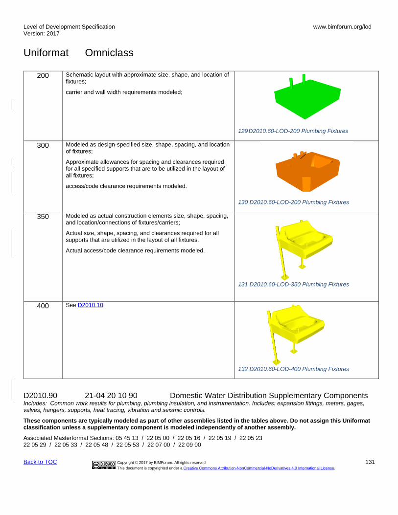
Level of Development Specification Version: 2017
www.bimforum.org/lod
Uniformat Omniclass
Back to TOC Copyright © 2017 by BIMForum. All rights reserved 131
This document is copyrighted under a Creative Commons Attribution-NonCommercial-NoDerivatives 4.0 International License.
200 Schematic layout with approximate size, shape, and location of fixtures;
carrier and wall width requirements modeled;
129 D2010.60-LOD-200 Plumbing Fixtures
300 Modeled as design-specified size, shape, spacing, and location of fixtures;
Approximate allowances for spacing and clearances required for all specified supports that are to be utilized in the layout of all fixtures;
access/code clearance requirements modeled.
130 D2010.60-LOD-200 Plumbing Fixtures
350 Modeled as actual construction elements size, shape, spacing, and location/connections of fixtures/carriers;
Actual size, shape, spacing, and clearances required for all supports that are utilized in the layout of all fixtures.
Actual access/code clearance requirements modeled.
131 D2010.60-LOD-350 Plumbing Fixtures
400 See D2010.10
132 D2010.60-LOD-400 Plumbing Fixtures
D2010.90 21-04 20 10 90 Domestic Water Distribution Supplementary Components Includes: Common work results for plumbing, plumbing insulation, and instrumentation. Includes: expansion fittings, meters, gages, valves, hangers, supports, heat tracing, vibration and seismic controls.
These components are typically modeled as part of other assemblies listed in the tables above. Do not assign this Uniformat classification unless a supplementary component is modeled independently of another assembly.
Associated Masterformat Sections: 05 45 13 / 22 05 00 / 22 05 16 / 22 05 19 / 22 05 23 22 05 29 / 22 05 33 / 22 05 48 / 22 05 53 / 22 07 00 / 22 09 00

Level of Development Specification Version: 2017
www.bimforum.org/lod
Uniformat Omniclass
Back to TOC Copyright © 2017 by BIMForum. All rights reserved 132
This document is copyrighted under a Creative Commons Attribution-NonCommercial-NoDerivatives 4.0 International License.
D2020 21-04 20 20 Sanitary Drainage Includes: Facility sanitary sewerage system located within, under, or closely associated with a structure. Include Sanitary Drainage Supplementary Components as appropriate.
Associated Masterformat Sections: 01 86 16 / 22 13 00
100 See D20
200 See D2010
D2020.10 21-04 20 20 10 Sanitary Sewerage Equipment Includes: Interceptor, separator, pumps, and septic tanks that are part of facility sanitary sewerage system.
Associated Masterformat Sections: 22 13 23 / 22 13 26 / 22 13 29 / 22 13 33 / 22 13 36 22 13 43 / 22 13 53
100 See D20
200 Schematic layout with approximate size, shape, and location of equipment;
133 D2020.10-LOD-200 Sanitary Sewerage Equipment
300 Modeled as design specified size, shape, spacing, and location of equipment;
Approximate allowances for spacing and clearances required for all specified anchors, supports, vibration and seismic control that are utilized in the layout of equipment are modeled.
access/code clearance requirements modeled.
134.D2020.10-LOD-300 Sanitary Sewerage Equipment
350 Actual size, shape, spacing, and clearances required for all specified anchors, supports, vibration and seismic control that are utilized in the layout of equipment;
actual access/code clearance requirements modeled.
135 D2020.10-LOD-350 Sanitary Sewerage Equipment

Level of Development Specification Version: 2017
www.bimforum.org/lod
Uniformat Omniclass
Back to TOC Copyright © 2017 by BIMForum. All rights reserved 133
This document is copyrighted under a Creative Commons Attribution-NonCommercial-NoDerivatives 4.0 International License.
400 Supplementary components added to the model required for fabrication and field installation
136 D2020.10-LOD-400 Sanitary Sewerage Equipment
D2020.30 21-04 20 20 30 Sanitary Sewerage Piping Includes: Sanitary waste and vent piping system within and under structures. May Include: Sanitary piping from the structure to the utility sanitary sewer.
Associated Masterformat Sections: 22 13 13 / 22 13 16 / 22 13 19 / 22 05 73 / 22 05 76
100 See D20
200 Schematic layout with approximate size, shape, and location of mains and risers; shaft requirements modeled;
137 D2020.30-LOD-200 Sanitary Sewerage Piping
300 Modeled as design-specified size, shape, spacing, location, and slope of pipe, valves, fittings, and insulation for risers, mains, and branches;
Approximate allowances for spacing and clearances required for all specified hangers, supports, vibration and seismic control that are to be utilized in the layout of all risers, mains, and branches;
access/code clearance requirements modeled 138 D2020.30-LOD-300 Sanitary Sewerage Piping

Level of Development Specification Version: 2017
www.bimforum.org/lod
Uniformat Omniclass
Back to TOC Copyright © 2017 by BIMForum. All rights reserved 134
This document is copyrighted under a Creative Commons Attribution-NonCommercial-NoDerivatives 4.0 International License.
350 Modeled as actual construction elements;
Actual size, shape, spacing, location, connections, and slope of pipe, valves, fittings, and insulation for risers, mains, and branches;
Actual size, shape, spacing, and clearances required for all hangers, supports, vibration and seismic control that are utilized in the layout of all risers, mains, and branches;
Actual floor and wall penetration elements modeled.
Actual access/code clearance requirements modeled
139 D2020.30-LOD-350 Sanitary Sewerage Piping
400 See D2020.10
140 D2020.30-LOD-400 Sanitary Sewerage Piping
D2020.90 21-04 20 20 90 Sanitary Drainage Supplementary Components Includes: Common work results for plumbing, plumbing insulation, and instrumentation and control for plumbing to be included with sanitary drainage elements above as appropriate. Includes expansion fittings, meters, gages, valves, hangers, supports, heat tracing, vibration and seismic controls.
These components are typically modeled as part of other assemblies listed in the tables above. Do not assign this Uniformat classification unless a supplementary component is modeled independently of another assembly.
Associated Masterformat Sections: 05 45 13 / 22 05 00 / 22 05 16 / 22 05 19 / 22 05 23 22 05 29 / 22 05 33 / 22 05 48 / 22 05 53 / 22 07 00 / 22 09 00
D2030 21-04 20 30 Building Support Plumbing Systems Includes: Facility storm water drainage and gray water systems. Include Building Support Plumbing System Supplementary Components as appropriate.
Associated Masterformat Sections: 01 86 16 / 22 14 00
100 See D20
200 See D2010
D2030.10 21-04 20 30 10 Stormwater Drainage Equipment Includes: Drainage pumps, and sump pumps that are part of stormwater drainage system.
Associated Masterformat Sections: 22 14 29 / 22 14 33 / 22 14 36 / 22 14 53

Level of Development Specification Version: 2017
www.bimforum.org/lod
Uniformat Omniclass
Back to TOC Copyright © 2017 by BIMForum. All rights reserved 135
This document is copyrighted under a Creative Commons Attribution-NonCommercial-NoDerivatives 4.0 International License.
100 Diagrammatic or schematic model elements;
conceptual and/or schematic layout;
200 Schematic layout with approximate size, shape, and location of equipment;
approximate access/code clearance requirements modeled;
141 D2030.10-LOD-200 Stormwater Drainage Equipment
300 Modeled as design-specified size, shape, spacing, and location of equipment;
approximate allowances for spacing and clearances required for all specified anchors, supports, vibration and seismic control that are utilized in the layout of equipment;
access/code clearance requirements modeled.
142 D2030.10-LOD-300 Stormwater Drainage Equipment
350 Modeled as actual construction elements size, shape, spacing, and location/connections of equipment,
actual size, shape, spacing, and clearances required for all specified anchors, supports, vibration and seismic control that are utilized in the layout of equipment;
actual access/code clearance requirements modeled.
143 D2030.10-LOD-350 Stormwater Drainage Equipment
400 Supplementary components added to the model required for fabrication and field installation.
144 D2030.10-LOD-400 Stormwater Drainage Equipment
D2030.20 21-04 20 30 20 Stormwater Drainage Piping Includes: Storm drainage piping system within, under, or closely associated with a structure. Includes storm drains for areas closely associated with a structure such as courtyards, plazas, and loading dock areas. May Include: Storm drainage piping from the structure to the utility storm drain.

Level of Development Specification Version: 2017
www.bimforum.org/lod
Uniformat Omniclass
Back to TOC Copyright © 2017 by BIMForum. All rights reserved 136
This document is copyrighted under a Creative Commons Attribution-NonCommercial-NoDerivatives 4.0 International License.
Associated Masterformat Sections: 22 05 73 / 22 05 76 / 22 14 13 / 22 14 16 / 22 14 23
100 See D20
200 Schematic layout with approximate size, shape, and location of mains and risers;
shaft requirements modeled;
145 D2030.20-LOD-200 Stormwater Drainage Piping
300 Modeled as design-specified size, shape, spacing, location, and slope of pipe, valves, fittings, and insulation for risers, mains, and branches;
approximate allowances for spacing and clearances required for all specified hangers, supports, vibration and seismic control that are to be utilized in the layout of all risers, mains, and branches;
access/code clearance requirements modeled.
146 D2030.20-LOD-300 Stormwater Drainage Piping
350 Modeled as actual size, shape, spacing, location, connections, and slope of pipe, valves, fittings, and insulation for risers, mains, and branches;
actual size and shape, spacing, and clearances required for all hangers, supports, vibration and seismic control that are utilized in the layout of all risers, mains, and branches;
Actual access/code clearance requirements modeled.
actual floor and wall penetration elements modeled.
147 D2030.20-LOD-350 Stormwater Drainage Piping

Level of Development Specification Version: 2017
www.bimforum.org/lod
Uniformat Omniclass
Back to TOC Copyright © 2017 by BIMForum. All rights reserved 137
This document is copyrighted under a Creative Commons Attribution-NonCommercial-NoDerivatives 4.0 International License.
400 See D2030.10
148 D2030.20-LOD-400 Stormwater Drainage Piping
D2030.30 21-04 20 30 30 Facility Stormwater Drains Includes: Various types of drains to collect storm water.
Associated Masterformat Sections: 22 14 26
100 See D20
200 Schematic layout with approximate size, shape, and location of components;
149 D2030.30-LOD-200 Facility Stormwater Drains

Level of Development Specification Version: 2017
www.bimforum.org/lod
Uniformat Omniclass
Back to TOC Copyright © 2017 by BIMForum. All rights reserved 138
This document is copyrighted under a Creative Commons Attribution-NonCommercial-NoDerivatives 4.0 International License.
300 Modeled as design-specified size, shape, spacing, and location of components;
approximate allowances for spacing and clearances required for all specified hangers, supports, vibration and seismic control that are to be utilized in the layout of all components;
access/code clearance requirements modeled.
150 D2030.30-LOD-300 Facility Stormwater Drains
350 Modeled as actual construction elements size, shape, spacing, and location/connections of components;
actual size, shape, spacing, and clearances required for all hangers, supports, vibration and seismic control that are utilized in the layout of all components.
Actual access/code clearance requirements modeled.
151 D2030.30-LOD-350 Facility Stormwater Drains
400 See D2030.10
152 D2030.30-LOD-400 Facility Stormwater Drains
D2030.60 21-04 20 30 60 Gray Water Systems Includes: Systems to collect, treat, and distribute gray water for other uses such as irrigation.
Associated Masterformat Sections: 22 13 63
[See D2030.20]
D2030.90 21-04 20 30 90 Building Support Plumbing System Supplementary Components Includes: Common work results for plumbing, plumbing insulation, and instrumentation and control for plumbing to be included with building support plumbing system elements above as appropriate. Includes expansion fittings, meters, gages, valves, hangers, supports, heat tracing, vibration and seismic controls.
These components are typically modeled as part of other assemblies listed in the tables above. Do not assign this Uniformat classification unless a supplementary component is modeled independently of another assembly.

Level of Development Specification Version: 2017
www.bimforum.org/lod
Uniformat Omniclass
Back to TOC Copyright © 2017 by BIMForum. All rights reserved 139
This document is copyrighted under a Creative Commons Attribution-NonCommercial-NoDerivatives 4.0 International License.
Associated Masterformat Sections: 05 45 13 / 22 05 00 / 22 05 16 / 22 05 19 / 22 05 23 22 05 29 / 22 05 33 / 22 05 48 / 22 05 53 / 22 07 00 / 22 09 00
D2050 21-04 20 50 General Service Compressed-Air Includes: Compressed air system serving general service requirements
Associated Masterformat Sections: 01 86 16 / 22 15 00 / 22 15 13 / 22 15 16 / 22 15 19
[See D2060.10 – Compressed-Air Systems]
D2060 21-04 20 60 Process Support Plumbing Systems Includes: Process Support Plumbing System Supplementary Components as appropriate.
Associated Masterformat Sections:
100 See D20
200 Schematic layout with approximate size, shape, and location of mains and risers;
shaft requirements modeled;
D2060.10 21-04 20 60 10 Compressed-Air Systems Associated Masterformat Sections: 01 86 16 / 22 61 00 / 22 61 13 / 22 61 19
100 See D20
200 See D2060
153 D2060.10-LOD-200 Compressed-Air Systems
300 Modeled as design-specified size, shape, spacing, location, and slope of equipment/pipe, valves, fittings, and insulation for risers, mains, and branches;
approximate allowances for spacing and clearances required for all specified hangers, supports, vibration and seismic control that are to be utilized in the layout of all risers, mains, and branches;
access/code clearance requirements modeled.
154 D2060.10-LOD-300 Compressed-Air Systems
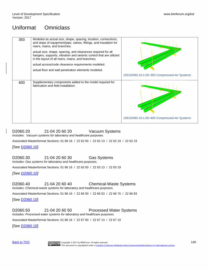
Level of Development Specification Version: 2017
www.bimforum.org/lod
Uniformat Omniclass
Back to TOC Copyright © 2017 by BIMForum. All rights reserved 140
This document is copyrighted under a Creative Commons Attribution-NonCommercial-NoDerivatives 4.0 International License.
350 Modeled as actual size, shape, spacing, location, connections, and slope of equipment/pipe, valves, fittings, and insulation for risers, mains, and branches;
actual size, shape, spacing, and clearances required for all hangers, supports, vibration and seismic control that are utilized in the layout of all risers, mains, and branches;
actual access/code clearance requirements modeled.
actual floor and wall penetration elements modeled.
155 D2060.10-LOD-350 Compressed-Air Systems
400 Supplementary components added to the model required for fabrication and field installation.
156 D2060.10-LOD-400 Compressed-Air Systems
D2060.20 21-04 20 60 20 Vacuum Systems Includes: Vacuum systems for laboratory and healthcare purposes.
Associated Masterformat Sections: 01 86 16 / 22 62 00 / 22 62 13 / 22 62 19 / 22 62 23
[See D2060.10]
D2060.30 21-04 20 60 30 Gas Systems Includes: Gas systems for laboratory and healthcare purposes.
Associated Masterformat Sections: 01 86 16 / 22 63 00 / 22 63 13 / 22 63 19
[See D2060.10]
D2060.40 21-04 20 60 40 Chemical-Waste Systems Includes: Chemical-waste systems for laboratory and healthcare purposes.
Associated Masterformat Sections: 01 86 16 / 22 66 00 / 22 66 53 / 22 66 70 / 22 66 83
[See D2060.10]
D2060.50 21-04 20 60 50 Processed Water Systems Includes: Processed water systems for laboratory and healthcare purposes.
Associated Masterformat Sections: 01 86 16 / 22 67 00 / 22 67 13 / 22 67 19
[See D2060.10]

Level of Development Specification Version: 2017
www.bimforum.org/lod
Uniformat Omniclass
Back to TOC Copyright © 2017 by BIMForum. All rights reserved 141
This document is copyrighted under a Creative Commons Attribution-NonCommercial-NoDerivatives 4.0 International License.
D2060.90 21-04 20 60 90 Process Support Plumbing System Supplementary Components Includes expansion fittings, meters, gages, valves, hangers, supports, heat tracing, vibration and seismic controls. Includes: Common work results for plumbing, plumbing insulation, and instrumentation and controls to be included with process support plumbing systems elements above as appropriate.
These components are typically modeled as part of other assemblies listed in the tables above. Do not assign this Uniformat classification unless a supplementary component is modeled independently of another assembly.
Associated Masterformat Sections: 05 45 13 / 05 45 23 / 22 05 00 / 22 05 23 / 22 05 29 / 22 05 33 / 22 05 48 / 22 05 53 / 22 07 00 / 22 09 00
D30 21-04 30 Heating, Ventilation, and Air Conditioning (HVAC) Associated Masterformat Sections: 01 86 19 / 23 00 00
100 Diagrammatic or schematic model elements;
conceptual and/or schematic layout/flow diagram;
D3010 21-04 30 10 Facility Fuel Systems Includes: Fuel-oil, gasoline, natural-gas, and liquefied-petroleum fuel systems associated with a structure.
Associated Masterformat Sections: 01 86 19 / 23 10 00
100 See D30
200 Schematic layout with approximate size, shape, and location of element(s);
approximate access/code clearance requirements modeled;
shaft requirements modeled;
D3010.10 21-04 30 10 10 Fuel Piping Includes: Fuel piping, valves, piping specialties, and other components within, under, or closely associated with a structure.
Associated Masterformat Sections: 23 11 00
100 See D30
200 See D3010
157 D3010.10-200 Fuel Piping

Level of Development Specification Version: 2017
www.bimforum.org/lod
Uniformat Omniclass
Back to TOC Copyright © 2017 by BIMForum. All rights reserved 142
This document is copyrighted under a Creative Commons Attribution-NonCommercial-NoDerivatives 4.0 International License.
300 Modeled as design-specified size, shape, spacing, and location of pipe, valves, fittings, and insulation for risers, mains, and branches;
approximate allowances for spacing and clearances required for all specified hangers, supports, vibration and seismic control that are to be utilized in the layout of all risers, mains, and branches;
access/code clearance requirements modeled.
158 D3010.10-300 Fuel Piping
350 Modeled as actual size, shape, spacing, and location/connections of pipe, valves, fittings, and insulation for risers, mains, and branches;
actual size, shape, spacing, and clearances required for all hangers, supports, vibration and seismic control that are utilized in the layout of all risers, mains, and branches;
actual access/code clearance requirements modeled.
actual floor and wall penetration elements modeled.
159 D3010.10-350 Fuel Piping
400 Supplementary components added to the model required for fabrication and field installation
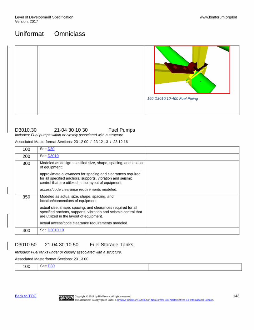
Level of Development Specification Version: 2017
www.bimforum.org/lod
Uniformat Omniclass
Back to TOC Copyright © 2017 by BIMForum. All rights reserved 143
This document is copyrighted under a Creative Commons Attribution-NonCommercial-NoDerivatives 4.0 International License.
160 D3010.10-400 Fuel Piping
D3010.30 21-04 30 10 30 Fuel Pumps Includes: Fuel pumps within or closely associated with a structure.
Associated Masterformat Sections: 23 12 00 / 23 12 13 / 23 12 16
100 See D30
200 See D3010
300 Modeled as design-specified size, shape, spacing, and location of equipment;
approximate allowances for spacing and clearances required for all specified anchors, supports, vibration and seismic control that are utilized in the layout of equipment;
access/code clearance requirements modeled.
350 Modeled as actual size, shape, spacing, and location/connections of equipment;
actual size, shape, spacing, and clearances required for all specified anchors, supports, vibration and seismic control that are utilized in the layout of equipment.
actual access/code clearance requirements modeled.
400 See D3010.10
D3010.50 21-04 30 10 50 Fuel Storage Tanks
Includes: Fuel tanks under or closely associated with a structure.
Associated Masterformat Sections: 23 13 00
100 See D30

Level of Development Specification Version: 2017
www.bimforum.org/lod
Uniformat Omniclass
Back to TOC Copyright © 2017 by BIMForum. All rights reserved 144
This document is copyrighted under a Creative Commons Attribution-NonCommercial-NoDerivatives 4.0 International License.
200 See D3010
161 D3010.50-LOD-200 Fuel Storage Tanks
300 Modeled as design-specified size, shape, spacing, and location of tank(s);
approximate allowances for spacing and clearances required for all specified anchors, supports, vibration and seismic control that are utilized in the layout of tanks(s);
access/code clearance requirements modeled.
162 D3010.50-LOD-300 Fuel Storage Tanks
350 Modeled as actual size, shape, spacing, and location/connections of tank(s);
actual size, shape, spacing, and clearances required for all specified anchors, supports, vibration and seismic control that are utilized in the layout of tanks(s).
actual access/code clearance requirements modeled.
163 D3010.50-LOD-350 Fuel Storage Tanks
400 See D3010.10
164 D3010.50-LOD-400 Fuel Storage Tanks
D3020 21-04 30 20 Heating Systems Includes: Associated ductwork, piping, valves, and specialties. Includes: Heating System Supplementary Components as appropriate.

Level of Development Specification Version: 2017
www.bimforum.org/lod
Uniformat Omniclass
Back to TOC Copyright © 2017 by BIMForum. All rights reserved 145
This document is copyrighted under a Creative Commons Attribution-NonCommercial-NoDerivatives 4.0 International License.
Associated Masterformat Sections: 01 86 19
100 See D30
200 Schematic layout with approximate size, shape, and location of element(s);
shaft requirements modeled;
D3020.10 21-04 30 20 10 Heat Generation Includes: Boilers, furnaces, solar, geothermal, and biomass heat generation, fuel fired heaters, and heat exchangers. Includes: Fuel-fired boilers and generators for hot water and steam systems. Includes breechings, chimneys, and stacks. Includes: Electric boilers and generators for hot water and steam systems. Includes: Equipment to remove oxygen and other dissolved gases in boiler feed. Includes: Fuel-fired and electric furnaces. Includes: Equipment powered by solar energy. Includes: Fuel-fired radiant and unit heaters. Includes: Equipment used to transfer heat from one medium to another.
Associated Masterformat Sections: 23 51 00 / 23 52 00 / 23 52 13 / 23 53 00 / 23 53 13 / 23 53 16 / 23 54 00 / 23 56 00 / 23 56 13 / 23 56 16 / 23 55 00 / 23 57 00
100 See D30
200 See D3020
165 D3020.10-LOD-200 Heat Generation
300 Modeled as design-specified size, shape, spacing, and location of equipment;
approximate allowances for spacing and clearances required for all specified anchors, supports, vibration and seismic control that are utilized in the layout of equipment;
access/code clearance requirements modeled.
166 D3020.10-LOD-300 Heat Generation

Level of Development Specification Version: 2017
www.bimforum.org/lod
Uniformat Omniclass
Back to TOC Copyright © 2017 by BIMForum. All rights reserved 146
This document is copyrighted under a Creative Commons Attribution-NonCommercial-NoDerivatives 4.0 International License.
350 Modeled as actual size, shape, spacing, and location/connections of equipment,
actual size, shape, spacing, and clearances required for all specified anchors, supports, vibration and seismic control that are utilized in the layout of equipment.
actual access/code clearance requirements modeled.
167 D3020.10-LOD-350 Heat Generation
400 Supplementary components added to the model required for fabrication and field installation.
168 D3020.10-LOD-400 Heat Generation
D3020.30 21-04 30 20 30 Thermal Heat Storage Includes: Equipment to store thermal energy for use in heating and with charging or discharging this energy at a controllable rate.
Associated Masterformat Sections: 23 71 13
[See D3020.10]
D3020.70 21-04 30 20 70 Decentralized Heating Equipment Includes: Heating equipment that serves a portion of a HVAC system. Includes: Convection units may provide heating and cooling. Includes: Electric cables or panels and hydronic piping used for radiant heating for space heating.
Associated Masterformat Sections: 23 80 00 / 23 82 00 / 23 82 13 / 23 82 14 / 23 82 16 / 23 82 19 / 23 82 23 / 23 82 26 / 23 82 29 / 23 82 33 / 23 82 36 / 23 82 39 / 23 83 00
[See D3020.10]
D3020.90 21-04 30 20 90 Heating System Supplementary Components Includes: Common work results for HVAC, insulation, and instrumentation and control to be included in heating system elements above as appropriate.
These components are typically modeled as part of other assemblies listed in the tables above. Do not assign this Uniformat classification unless a supplementary component is modeled independently of another assembly.
Associated Masterformat Sections: 05 45 13 / 23 05 00 / 23 05 19 / 23 05 23 / 23 05 29 / 23 05 48 / 23 05 53 / 23 05 63 / 23 05 66 / 23 05 93 / 23 07 00 / 23 09 00
D3030 21-04 30 30 Cooling Systems Includes: Associated ductwork, piping, valves, and specialties. Includes: Cooling System Supplementary Components as appropriate.
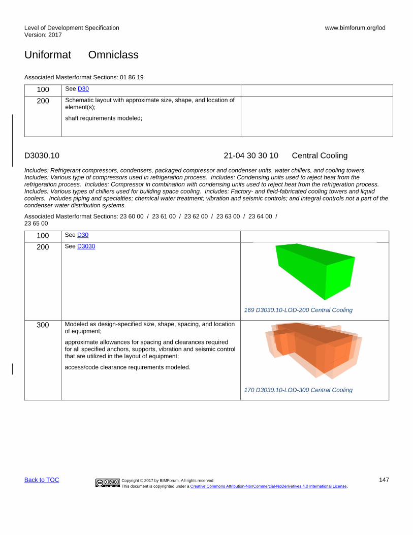
Level of Development Specification Version: 2017
www.bimforum.org/lod
Uniformat Omniclass
Back to TOC Copyright © 2017 by BIMForum. All rights reserved 147
This document is copyrighted under a Creative Commons Attribution-NonCommercial-NoDerivatives 4.0 International License.
Associated Masterformat Sections: 01 86 19
100 See D30
200 Schematic layout with approximate size, shape, and location of element(s);
shaft requirements modeled;
D3030.10 21-04 30 30 10 Central Cooling
Includes: Refrigerant compressors, condensers, packaged compressor and condenser units, water chillers, and cooling towers. Includes: Various type of compressors used in refrigeration process. Includes: Condensing units used to reject heat from the refrigeration process. Includes: Compressor in combination with condensing units used to reject heat from the refrigeration process. Includes: Various types of chillers used for building space cooling. Includes: Factory- and field-fabricated cooling towers and liquid coolers. Includes piping and specialties; chemical water treatment; vibration and seismic controls; and integral controls not a part of the condenser water distribution systems.
Associated Masterformat Sections: 23 60 00 / 23 61 00 / 23 62 00 / 23 63 00 / 23 64 00 / 23 65 00
100 See D30
200 See D3030
169 D3030.10-LOD-200 Central Cooling
300 Modeled as design-specified size, shape, spacing, and location of equipment;
approximate allowances for spacing and clearances required for all specified anchors, supports, vibration and seismic control that are utilized in the layout of equipment;
access/code clearance requirements modeled.
170 D3030.10-LOD-300 Central Cooling

Level of Development Specification Version: 2017
www.bimforum.org/lod
Uniformat Omniclass
Back to TOC Copyright © 2017 by BIMForum. All rights reserved 148
This document is copyrighted under a Creative Commons Attribution-NonCommercial-NoDerivatives 4.0 International License.
350 Modeled as actual size, shape, spacing, and location/connections of equipment;
actual size, shape, spacing, and clearances required for all specified anchors, supports, vibration and seismic control that are utilized in the layout of equipment.
actual access/code clearance requirements modeled.
171 D3030.10-LOD-350 Central Cooling
400 Supplementary components added to the model required for fabrication and field installation.
172 D3030.10-LOD-400 Central Cooling
D3030.30 21-04 30 30 30 Evaporative Air-Cooling Includes: Equipment used to reject heat from the refrigeration process by evaporation.
Associated Masterformat Sections: 23 76 00
100 See D3030.10
200 See D3030.10
173 D3030.30-LOD-200 Evaporative Air-Cooling

Level of Development Specification Version: 2017
www.bimforum.org/lod
Uniformat Omniclass
Back to TOC Copyright © 2017 by BIMForum. All rights reserved 149
This document is copyrighted under a Creative Commons Attribution-NonCommercial-NoDerivatives 4.0 International License.
300 See D3030.10
174 D3030.30-LOD-300 Evaporative Air-Cooling
350 See D3030.10
175 D3030.30-LOD-350 Evaporative Air-Cooling
400 See D3030.10
176 D3030.30-LOD-400 Evaporative Air-Cooling
D3030.50 21-04 30 30 50 Thermal Cooling Storage Includes: Equipment to store thermal energy for use in cooling and with charging or discharging this energy at a controllable rate.
Associated Masterformat Sections: 23 71 00 / 23 71 16 / 23 71 19
[See D3030.10]
D3030.70 21-04 30 30 70 Decentralized Cooling Includes: Cooling equipment that serves a portion of a HVAC system. Note: Convection units may provide heating and cooling.
Associated Masterformat Sections: 23 80 00 / 23 81 13 / 23 81 16 / 23 81 19 / 23 81 23 / 23 81 26 / 23 81 43 / 23 81 46 / 23 82 00 / 23 82 13 / 23 82 14 / 23 82 16 / 23 82 19 / 23 82 23 / 23 82 26

Level of Development Specification Version: 2017
www.bimforum.org/lod
Uniformat Omniclass
Back to TOC Copyright © 2017 by BIMForum. All rights reserved 150
This document is copyrighted under a Creative Commons Attribution-NonCommercial-NoDerivatives 4.0 International License.
[See D3030.10]
D3030.90 21-04 30 30 90 Cooling System Supplementary Components Includes expansion fittings, meters, gages, valves, hangers, supports, heat tracing, vibration and seismic controls. Includes: Common work results for HVAC, insulation, and instrumentation and control to be included in cooling system elements above as appropriate.
These components are typically modeled as part of other assemblies listed in the tables above. Do not assign this Uniformat classification unless a supplementary component is modeled independently of another assembly.
Associated Masterformat Sections: 05 45 13 / 23 05 00 / 23 05 19 / 23 05 23 / 23 05 29 / 23 05 48 / 23 05 53 / 23 05 63 / 23 05 66 / 23 05 93 / 23 07 00 / 23 09 00
D3050 21-04 30 50 Facility HVAC Distribution Systems Includes: Facility Distribution Systems Supplementary Components as appropriate.
Associated Masterformat Sections:
100 See D30
200 Schematic layout with approximate size, shape, and location of element(s);
D3050.10 21-04 30 50 10 Facility Hydronic Distribution
Includes: Piping systems and equipment for distribution of heating hot water and cooling chilled water. Includes piping systems, pumps, tanks, supports and anchors, vibration and seismic controls, identification, and piping and equipment insulation.
Associated Masterformat Sections: 01 86 19 / 23 21 13 / 23 21 23 / 23 25 00
100 See D30
200 See D3050
177 D3050.10-LOD-200 Facility Hydronic distribution

Level of Development Specification Version: 2017
www.bimforum.org/lod
Uniformat Omniclass
Back to TOC Copyright © 2017 by BIMForum. All rights reserved 151
This document is copyrighted under a Creative Commons Attribution-NonCommercial-NoDerivatives 4.0 International License.
300 Modeled as design-specified size, shape, spacing, location, and slope of pipe, valves, fittings, and insulation for risers, mains, and branches;
approximate allowances for spacing and clearances required for all specified hangers, supports, vibration and seismic control that are to be utilized in the layout of all risers, mains, and branches;
access/code clearance requirements modeled.
178 D3050.10-LOD-300 Facility Hydronic Distribution
350 Modeled as actual size, shape, spacing, location, connections, and slope of pipe, valves, fittings, and insulation for risers, mains, and branches;
actual size, shape, spacing, and clearances required for all hangers, supports, vibration and seismic control that are utilized in the layout of all risers, mains, and branches;
actual floor and wall penetration elements modeled.
actual access/code clearance requirements modeled.
400
Supplementary components added to the model required for fabrication and field installation.
179 D3050.10-LOD-350 Facility Hydronic Distribution
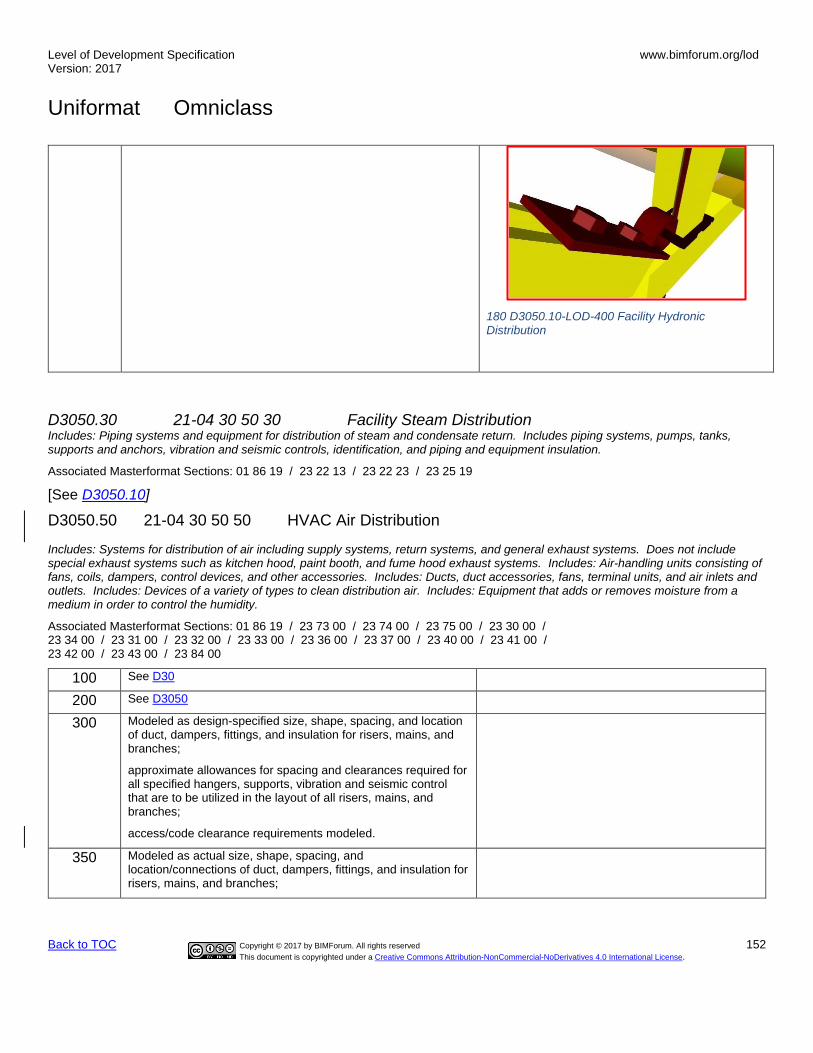
Level of Development Specification Version: 2017
www.bimforum.org/lod
Uniformat Omniclass
Back to TOC Copyright © 2017 by BIMForum. All rights reserved 152
This document is copyrighted under a Creative Commons Attribution-NonCommercial-NoDerivatives 4.0 International License.
180 D3050.10-LOD-400 Facility Hydronic Distribution
D3050.30 21-04 30 50 30 Facility Steam Distribution Includes: Piping systems and equipment for distribution of steam and condensate return. Includes piping systems, pumps, tanks, supports and anchors, vibration and seismic controls, identification, and piping and equipment insulation.
Associated Masterformat Sections: 01 86 19 / 23 22 13 / 23 22 23 / 23 25 19
[See D3050.10]
D3050.50 21-04 30 50 50 HVAC Air Distribution
Includes: Systems for distribution of air including supply systems, return systems, and general exhaust systems. Does not include special exhaust systems such as kitchen hood, paint booth, and fume hood exhaust systems. Includes: Air-handling units consisting of fans, coils, dampers, control devices, and other accessories. Includes: Ducts, duct accessories, fans, terminal units, and air inlets and outlets. Includes: Devices of a variety of types to clean distribution air. Includes: Equipment that adds or removes moisture from a medium in order to control the humidity.
Associated Masterformat Sections: 01 86 19 / 23 73 00 / 23 74 00 / 23 75 00 / 23 30 00 / 23 34 00 / 23 31 00 / 23 32 00 / 23 33 00 / 23 36 00 / 23 37 00 / 23 40 00 / 23 41 00 / 23 42 00 / 23 43 00 / 23 84 00
100 See D30
200 See D3050
300 Modeled as design-specified size, shape, spacing, and location of duct, dampers, fittings, and insulation for risers, mains, and branches;
approximate allowances for spacing and clearances required for all specified hangers, supports, vibration and seismic control that are to be utilized in the layout of all risers, mains, and branches;
access/code clearance requirements modeled.
350 Modeled as actual size, shape, spacing, and location/connections of duct, dampers, fittings, and insulation for risers, mains, and branches;

Level of Development Specification Version: 2017
www.bimforum.org/lod
Uniformat Omniclass
Back to TOC Copyright © 2017 by BIMForum. All rights reserved 153
This document is copyrighted under a Creative Commons Attribution-NonCommercial-NoDerivatives 4.0 International License.
actual size, shape, spacing, and clearances required for all hangers, supports, vibration and seismic control that are utilized in the layout of all risers, mains, and branches;
actual floor and wall penetration elements modeled.
actual access/code clearance requirements modeled.
400 See D3050.10
D3050.90 21-04 30 50 90 Facility Distribution Systems Supplementary Components Includes expansion fittings, meters, gages, valves, hangers, supports, heat tracing, vibration and seismic controls. Includes: Common work results for HVAC, insulation, and instrumentation and control to be included in distribution system elements above as appropriate.
These components are typically modeled as part of other assemblies listed in the tables above. Do not assign this Uniformat classification unless a supplementary component is modeled independently of another assembly.
Associated Masterformat Sections: 05 45 13 / 23 05 00 / 23 05 16 / 23 05 19 / 23 05 23 / 23 05 29 / 23 05 33 / 23 05 48 / 23 05 53 / 23 05 63 / 23 05 66 / 23 05 93 / 23 07 00 / 23 09 00
D3060 21-04 30 60 Ventilation
Includes: Supply air, return air, exhaust air, outside air, and air cleaning systems. Includes Ventilation Supplementary Components as appropriate.
Associated Masterformat Sections: 01 86 19
100 See D30
200 Schematic layout with approximate size, shape, and location of mains and risers;
D3060.10 21-04 30 60 10 Supply Air Associated Masterformat Sections: 23 34 00 / 23 31 00 / 23 32 00 / 23 33 00 / 23 36 00 / 23 37 00
100 See D30
200 See D3060
181 D3060.10-LOD-200 Supply Air

Level of Development Specification Version: 2017
www.bimforum.org/lod
Uniformat Omniclass
Back to TOC Copyright © 2017 by BIMForum. All rights reserved 154
This document is copyrighted under a Creative Commons Attribution-NonCommercial-NoDerivatives 4.0 International License.
300 Modeled as design-specified size, shape, spacing, and location of duct, dampers, fittings, and insulation for risers, mains, and branches;
approximate specified allowances for spacing and clearances required for all hangers, supports, vibration and seismic control that are to be utilized in the layout of all risers, mains, and branches;
access/code clearance requirements modeled.
182 D3060.10-LOD-300 Supply Air
350 Modeled as actual size, shape, spacing, and location/connections of duct, dampers, fittings, and insulation for risers, mains, and branches;
actual size, shape, spacing, and clearances required for all hangers, supports, vibration and seismic control that are utilized in the layout of all risers, mains, and branches;
actual floor and wall penetration elements modeled.
actual access/code clearance requirements modeled.
183 D3060.10-LOD-350 Supply Air
400 Supplementary components added to the model required for fabrication and field installation.
184 D3060.10-LOD-400 Supply Air
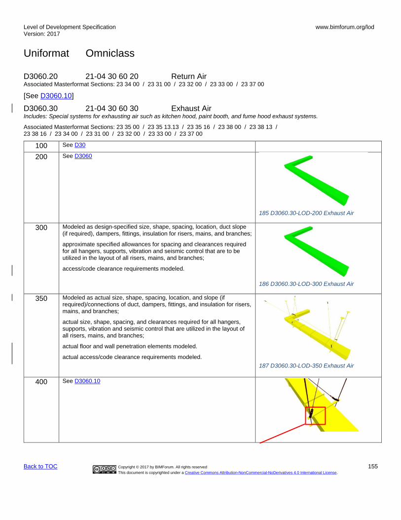
Level of Development Specification Version: 2017
www.bimforum.org/lod
Uniformat Omniclass
Back to TOC Copyright © 2017 by BIMForum. All rights reserved 155
This document is copyrighted under a Creative Commons Attribution-NonCommercial-NoDerivatives 4.0 International License.
D3060.20 21-04 30 60 20 Return Air Associated Masterformat Sections: 23 34 00 / 23 31 00 / 23 32 00 / 23 33 00 / 23 37 00
[See D3060.10]
D3060.30 21-04 30 60 30 Exhaust Air Includes: Special systems for exhausting air such as kitchen hood, paint booth, and fume hood exhaust systems.
Associated Masterformat Sections: 23 35 00 / 23 35 13.13 / 23 35 16 / 23 38 00 / 23 38 13 / 23 38 16 / 23 34 00 / 23 31 00 / 23 32 00 / 23 33 00 / 23 37 00
100 See D30
200 See D3060
185 D3060.30-LOD-200 Exhaust Air
300 Modeled as design-specified size, shape, spacing, location, duct slope (if required), dampers, fittings, insulation for risers, mains, and branches;
approximate specified allowances for spacing and clearances required for all hangers, supports, vibration and seismic control that are to be utilized in the layout of all risers, mains, and branches;
access/code clearance requirements modeled.
186 D3060.30-LOD-300 Exhaust Air
350 Modeled as actual size, shape, spacing, location, and slope (if required)/connections of duct, dampers, fittings, and insulation for risers, mains, and branches;
actual size, shape, spacing, and clearances required for all hangers, supports, vibration and seismic control that are utilized in the layout of all risers, mains, and branches;
actual floor and wall penetration elements modeled.
actual access/code clearance requirements modeled.
187 D3060.30-LOD-350 Exhaust Air
400 See D3060.10

Level of Development Specification Version: 2017
www.bimforum.org/lod
Uniformat Omniclass
Back to TOC Copyright © 2017 by BIMForum. All rights reserved 156
This document is copyrighted under a Creative Commons Attribution-NonCommercial-NoDerivatives 4.0 International License.
188 D3060.30-LOD-400 Exhaust Air
D3060.40 21-04 30 60 40 Outside Air Associated Masterformat Sections: 23 34 00 / 23 31 00 / 23 32 00 / 23 33 00 / 23 36 00 / 23 37 00
[See D3060.10]
D3060.60 21-04 30 60 60 Air-to-Air Energy Recovery Includes: Air-to-air energy recovery units.
Associated Masterformat Sections: 23 72 00
[See D3060.10]
D3060.70 21-04 30 60 70 HVAC Air Cleaning Associated Masterformat Sections: 23 40 00
[See D3060.10]
D3060.90 21-04 30 60 90 Ventilation Supplementary Components Includes expansion fittings, meters, gages, valves, hangers, supports, heat tracing, vibration and seismic controls. Includes: Common work results for HVAC, insulation, and instrumentation and control to be included in ventilation elements above as appropriate.
These components are typically modeled as part of other assemblies listed in the tables above. Do not assign this Uniformat classification unless a supplementary component is modeled independently of another assembly.
Associated Masterformat Sections: 05 45 13 / 23 05 00 / 23 05 29 / 23 05 48 / 23 05 53 / 23 05 63 / 23 05 66 / 23 05 93 / 23 07 00 / 23 09 00
D3070 21-04 30 70 Special Purpose HVAC Systems Associated Masterformat Sections:
100 See D30
200 Schematic layout with approximate size, shape, and location of components;
D3070.10 21-04 30 70 10 Snow Melting Includes: Electric cables and hydronic piping used for snow and ice control.
Associated Masterformat Sections: 23 83 13 / 23 83 16

Level of Development Specification Version: 2017
www.bimforum.org/lod
Uniformat Omniclass
Back to TOC Copyright © 2017 by BIMForum. All rights reserved 157
This document is copyrighted under a Creative Commons Attribution-NonCommercial-NoDerivatives 4.0 International License.
100 See D30
200 See D3070
300 Modeled as design-specified size, shape, spacing, and location of supplementary components;
approximate allowances for spacing and clearances required for all specified hangers, supports, vibration and seismic control that are to be utilized in the layout of all supplementary components;
access/code clearance requirements modeled.
350 Modeled as actual size, shape, spacing, and location/connections of supplementary components;
actual size, shape, spacing, and clearances required for all hangers, supports, vibration and seismic control that are utilized in the layout of all supplementary components.
actual access/code clearance requirements modeled.
400 Supplementary components added to the model required for fabrication and field installation.
D40 21-04 40 Fire Protection Associated Masterformat Sections:
100 Diagrammatic or schematic model elements;
conceptual and/or schematic layout/flow diagram;
D4010 21-04 40 10 Fire Suppression Includes: Fire Suppression Supplementary Components as appropriate.
Associated Masterformat Sections: 01 86 13 / 21 00 00
100 See D40
200 Schematic layout with approximate size, shape, and location of mains and risers;
D4010.10 21-04 40 10 10 Water-Based Fire-Suppression Includes: Systems that use water for fire extinguishing and suppression. Includes piping, fittings, and specialties; hoses, valves, cabinets; fire pumps, accessories, and controls. Includes: Piping, fittings, valves, hangers, supports, other specialties, and sprinklers for fire protection systems. Includes limited area sprinkler systems, fire pumps, accessories, and controls.
Associated Masterformat Sections: 01 86 13 / 21 10 00 / 21 11 00 / 21 12 00 / 21 13 00 / 21 13 13 / 21 13 16 / 21 13 19 / 21 13 23 / 21 13 26 / 21 13 29 / 21 13 36 / 21 13 39 / 21 30 00 / 21 40 00

Level of Development Specification Version: 2017
www.bimforum.org/lod
Uniformat Omniclass
Back to TOC Copyright © 2017 by BIMForum. All rights reserved 158
This document is copyrighted under a Creative Commons Attribution-NonCommercial-NoDerivatives 4.0 International License.
100 See D40
200 See D4010
189 D4010.10-LOD-200 Water-Based Fire-Suppression
300 Modeled as design-specified size, shape, spacing, and location of pipe/slope (if required)/valves/fittings/insulation for risers, mains, and branches/standpipes;
approximate allowances for spacing and clearances required for all specified hangers, supports, vibration and seismic control that are to be utilized in the layout of all risers, mains, and branches/standpipes;
access/code clearance requirements modeled.
190 D4010.10-LOD-300 Water-Based Fire-Suppression
350 Modeled as actual size, shape, spacing, and location/ slope (if required)/connections of pipe, valves, fittings, and insulation for risers, mains, and branches/standpipes;
actual size, shape, spacing, and clearances required for all hangers, supports, vibration and seismic control that are utilized in the layout of all risers, mains, and branches/standpipes;
actual floor and wall penetration elements modeled.
actual access/code clearance requirements modeled.
191 D4010.10-LOD-350 Water-Based Fire-Suppression
400 Supplementary components added to the model required for fabrication and field installation.
192 D4010.10-LOD-400 Water-Based Fire-Suppression
D4010.50 21-04 40 10 50 Fire-Extinguishing Includes: Systems that use other than water for fire extinguishing and suppression. Includes piping, fittings, and specialties; valves, accessories, and controls.
Level of Development Specification Version: 2017
www.bimforum.org/lod
Uniformat Omniclass
Back to TOC Copyright © 2017 by BIMForum. All rights reserved 159
This document is copyrighted under a Creative Commons Attribution-NonCommercial-NoDerivatives 4.0 International License.
Associated Masterformat Sections: 21 20 00 / 21 21 00 / 21 22 00 / 21 23 00 / 21 24 00
[See D4010.10]
D4010.90 21-04 40 10 90 Fire Suppression Supplementary Components Includes: Expansion fittings and loops, meters and gages, general-duty valves, hanger and supports, heat tracing, vibration and seismic controls, identification, insulation, and instrumentation and control to be included in fire protection elements above as appropriate.
These components are typically modeled as part of other assemblies listed in the tables above. Do not assign this Uniformat classification unless a supplementary component is modeled independently of another assembly.
Associated Masterformat Sections: 05 45 13 / 21 05 00 / 21 05 16 / 21 05 19 / 21 05 23 / 21 05 29 / 21 05 33 / 21 05 48 / 21 05 53 / 21 07 00 / 21 09 00
D4030 21-04 40 30 Fire Protection Specialties Includes: Firefighting devices and storage cabinets except devices connected to a fire suppression system.
Associated Masterformat Sections: 10 44 00
100 See D40
200 Schematic layout with approximate size, shape, and location of components;
D4030.10 21-04 40 30 10 Fire Protection Cabinets Associated Masterformat Sections: 10 44 13
100 See D40
200 See D4030
300 Modeled as design-specified size, shape, spacing, and location of components;
approximate allowances for spacing and clearances required for all specified hangers, supports, vibration and seismic control that are to be utilized in the layout of all components;
access/code clearance requirements modeled.
350 Modeled as actual size, shape, spacing, and location/connections of components;
actual size, shape, spacing, and clearances required for all hangers, supports, vibration and seismic control that are utilized in the layout of all components.
actual access/code clearance requirements modeled.
400 Supplementary components added to the model required for fabrication and field installation.
D4030.30 21-04 40 30 30 Fire Extinguishers Associated Masterformat Sections: 10 44 16
[See D4030.10]

Level of Development Specification Version: 2017
www.bimforum.org/lod
Uniformat Omniclass
Back to TOC Copyright © 2017 by BIMForum. All rights reserved 160
This document is copyrighted under a Creative Commons Attribution-NonCommercial-NoDerivatives 4.0 International License.
D4030.50 21-04 40 30 50 Breathing Air Replenishment Systems Associated Masterformat Sections: 10 44 33
[See D4030.10]
D4030.70 21-04 40 30 70 Fire Extinguisher Accessories Associated Masterformat Sections: 10 44 43
[See D4030.10]
D50 21-04 50 Electrical Associated Masterformat Sections: 26 00 00 / 01 86 26
100 Diagrammatic or schematic model elements:
conceptual and/or schematic layout;
D5010 21-04 50 10 Facility Power Generation Includes: Power Generation Supplementary Components as appropriate.
Associated Masterformat Sections: 01 86 26
100 See D50
200 Schematic layout with approximate size, shape, and location of equipment;
D5010.10 21-04 50 10 10 Packaged Generator Assemblies Includes: Generator, frequency changers, and rotary converters and uninterruptible power units.
Associated Masterformat Sections: 26 32 00 / 26 32 13 / 26 32 16 / 26 32 19 / 26 32 23 / 26 32 26 / 26 32 29 / 26 32 33
100 See D50
200 See D5010
193 D5010.10-LOD-200 Packaged Generator Assemblies

Level of Development Specification Version: 2017
www.bimforum.org/lod
Uniformat Omniclass
Back to TOC Copyright © 2017 by BIMForum. All rights reserved 161
This document is copyrighted under a Creative Commons Attribution-NonCommercial-NoDerivatives 4.0 International License.
300 Modeled as design-specified size, shape, spacing, and location of equipment and associated components;
approximate allowances for spacing and clearances required for all specified supports and seismic control;
access/code clearance requirements modeled.
194 D5010.10-LOD-300 Packaged Generator Assemblies
350 Modeled as actual size, shape, spacing, and location of equipment and associated components;
actual size, shape, spacing, and location for supports and seismic control;
actual size, shape, and location/connections of equipment and support structure/pads.
actual access/code clearance requirements modeled.
195 D5010.10-LOD-350 Packaged Generator Assemblies
400 Supplementary components added to the model required for fabrication and field installation.
196 D5010.10-LOD-400 Packaged Generator Assemblies
D5010.20 21-04 50 10 20 Battery Equipment Includes: Batteries, battery racks, battery chargers, static power converters, uninterruptible power supplies, and accessories.
Associated Masterformat Sections: 26 33 00 / 26 33 13 / 26 33 16 / 26 33 19 / 26 33 23 / 26 33 33 / 26 33 43 / 26 33 46 / 26 33 53
[See D5010.10]
D5010.30 21-04 50 10 30 Photovoltaic Collectors Includes: Solar cells to convert sunlight to electricity.
Associated Masterformat Sections: 26 31 00
[See D5010.10]

Level of Development Specification Version: 2017
www.bimforum.org/lod
Uniformat Omniclass
Back to TOC Copyright © 2017 by BIMForum. All rights reserved 162
This document is copyrighted under a Creative Commons Attribution-NonCommercial-NoDerivatives 4.0 International License.
D5010.40 21-04 50 10 40 Fuel Cells Includes: Fuel cell electricity generating equipment.
Associated Masterformat Sections: 48 18 00
[See D5010.10]
D5010.60 21-04 5010 60 Power Filtering and Conditioning TBD
D5010.70 21-04 50 10 70 Transfer Switches Includes: Switches that transfer from one source of electricity to another.
Associated Masterformat Sections: 26 36 00
[See D5010.10]
D5010.90 21-05 50 10 90 Facility Power Generation Supplementary TBD Components
D5020 21-04 50 20 Electrical Service and Distribution Includes: Electrical Service and Distribution Supplementary Components as appropriate.
Associated Masterformat Sections: 01 86 26
100 See D50
200 Schematic layout with approximate size, shape, and location of equipment;
D5020.10 21-04 50 20 10 Electrical Service Entrance Includes: Meters, substations, transformers, switchgear, switchboards, and protective devices where electrical power enters structure.
Associated Masterformat Sections: 26 21 00 / 26 16 00 / 26 11 00 / 26 12 00 / 26 22 00 / 26 13 00 / 22 23 00 / 26 18 00 / 22 28 00
100 See D50
200 See D5020
300 Modeled as design-specified size, shape, spacing, and location of equipment and associated components;
approximate allowances for spacing and clearances required for all specified supports and seismic control;
access/code clearance requirements modeled.
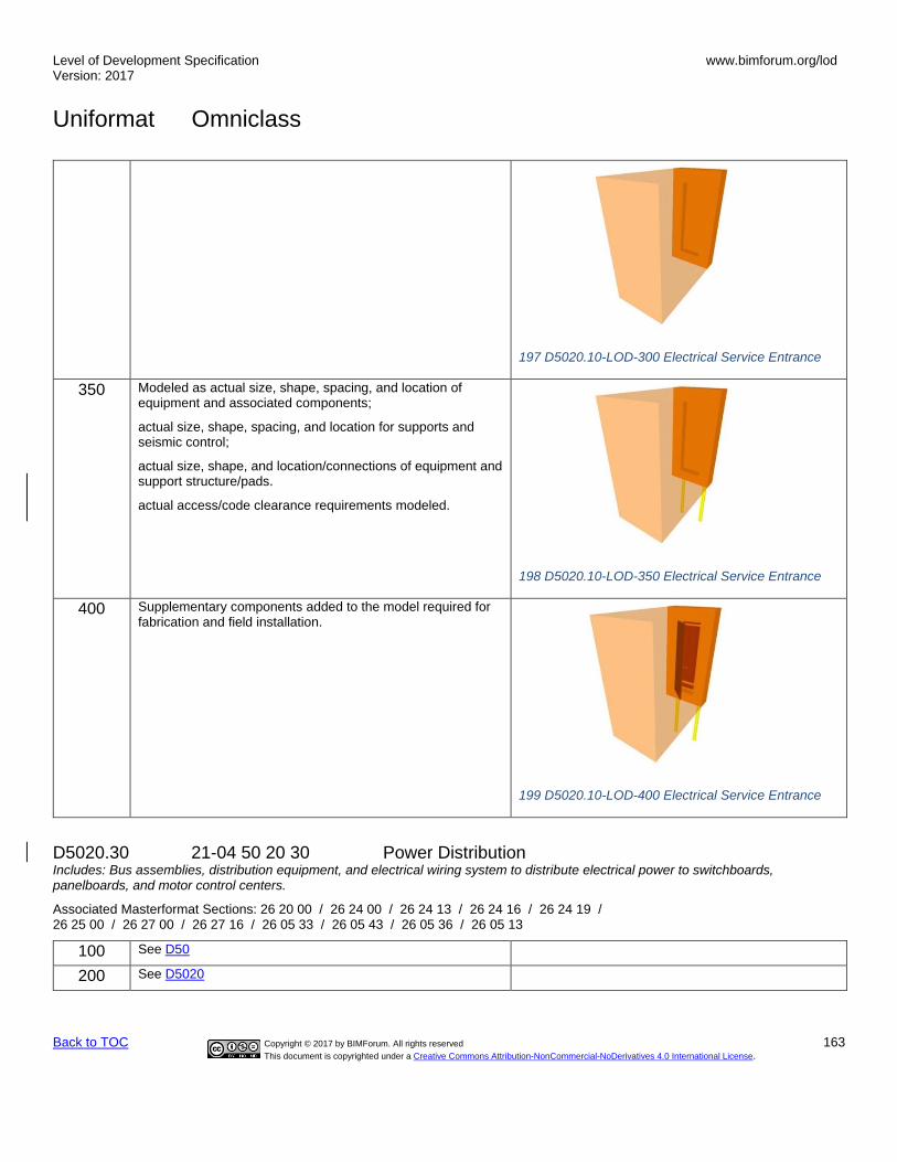
Level of Development Specification Version: 2017
www.bimforum.org/lod
Uniformat Omniclass
Back to TOC Copyright © 2017 by BIMForum. All rights reserved 163
This document is copyrighted under a Creative Commons Attribution-NonCommercial-NoDerivatives 4.0 International License.
197 D5020.10-LOD-300 Electrical Service Entrance
350 Modeled as actual size, shape, spacing, and location of equipment and associated components;
actual size, shape, spacing, and location for supports and seismic control;
actual size, shape, and location/connections of equipment and support structure/pads.
actual access/code clearance requirements modeled.
198 D5020.10-LOD-350 Electrical Service Entrance
400 Supplementary components added to the model required for fabrication and field installation.
199 D5020.10-LOD-400 Electrical Service Entrance
D5020.30 21-04 50 20 30 Power Distribution Includes: Bus assemblies, distribution equipment, and electrical wiring system to distribute electrical power to switchboards, panelboards, and motor control centers.
Associated Masterformat Sections: 26 20 00 / 26 24 00 / 26 24 13 / 26 24 16 / 26 24 19 / 26 25 00 / 26 27 00 / 26 27 16 / 26 05 33 / 26 05 43 / 26 05 36 / 26 05 13
100 See D50
200 See D5020

Level of Development Specification Version: 2017
www.bimforum.org/lod
Uniformat Omniclass
Back to TOC Copyright © 2017 by BIMForum. All rights reserved 164
This document is copyrighted under a Creative Commons Attribution-NonCommercial-NoDerivatives 4.0 International License.
300 Modeled as design-specified size, shape, spacing, and location of raceways, boxes, enclosures, and equipment;
approximate allowances for spacing and clearances required for all specified hangers, supports and seismic control;
access/code clearance requirements modeled.
200 D5020.30-LOD-300 Power Distribution
350 Modeled as actual size, shape, spacing, and location of raceways, boxes, and enclosures;
actual size, shape, spacing, and location for supports and seismic control;
actual size, shape, and location/connections of equipment and support structure/pads;
actual floor and wall penetration elements are modeled.
actual access/code clearance requirements modeled.
201 D5020.30-LOD-350 Power Distribution
400 Supplementary components added to the model required for fabrication and field installation.
202 D5020.30-LOD-400 Power Distribution
D5020.70 21-04 50 20 70 Facility Grounding Includes: Raceways, wiring and devices for grounding and bonding an electrical distribution system.
Associated Masterformat Sections: 26 05 26 / 26 05 33 / 26 05 13

Level of Development Specification Version: 2017
www.bimforum.org/lod
Uniformat Omniclass
Back to TOC Copyright © 2017 by BIMForum. All rights reserved 165
This document is copyrighted under a Creative Commons Attribution-NonCommercial-NoDerivatives 4.0 International License.
100 See D50
200 See D5020
300 Modeled as design-specified size, shape, spacing, and location of raceways, boxes, enclosures, and the electrical equipment and end-devices served;
approximate allowances for spacing and clearances required for all specified hangers, supports, and seismic control;
access/code clearance requirements modeled.
350 Modeled as actual size, shape, spacing, and location of raceways, boxes, enclosures, and the electrical equipment and end-devices served;
actual size, shape, spacing, and location for supports and seismic control;
actual floor and wall penetration elements are modeled.
actual access/code clearance requirements modeled.
400 Supplementary components added to the model required for fabrication and field installation.
D5020.90 21-04 50 20 90 Electrical Service and Distribution TBD Supplementary Components
D5030 21-04 50 30 General Purpose Electrical Power Includes: General Purpose Electrical Power Supplementary Components as appropriate.
Associated Masterformat Sections: 01 86 26
100 See D50
200 Schematic layout with approximate size, shape, and location of equipment;
D5030.10 21-04 50 30 10 Branch Wiring System Includes: Raceways, ducts, cable trays, and wiring to deliver power from branch panelboards to the point of use.
Associated Masterformat Sections: 26 05 33 / 26 05 43 / 26 05 36 / 26 05 19
100 See D50
200 See D5030
300 Modeled as design-specified size, shape, spacing, and location of raceways, boxes, and enclosures;
approximate allowances for spacing and clearances required for all specified hangers, supports and seismic control;
access/code clearance requirements modeled.
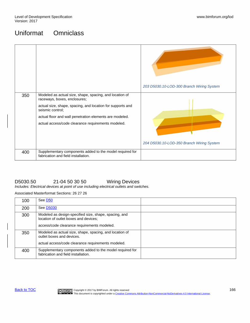
Level of Development Specification Version: 2017
www.bimforum.org/lod
Uniformat Omniclass
Back to TOC Copyright © 2017 by BIMForum. All rights reserved 166
This document is copyrighted under a Creative Commons Attribution-NonCommercial-NoDerivatives 4.0 International License.
203 D5030.10-LOD-300 Branch Wiring System
350 Modeled as actual size, shape, spacing, and location of raceways, boxes, enclosures;
actual size, shape, spacing, and location for supports and seismic control;
actual floor and wall penetration elements are modeled.
actual access/code clearance requirements modeled.
204 D5030.10-LOD-350 Branch Wiring System
400 Supplementary components added to the model required for fabrication and field installation.
D5030.50 21-04 50 30 50 Wiring Devices Includes: Electrical devices at point of use including electrical outlets and switches.
Associated Masterformat Sections: 26 27 26
100 See D50
200 See D5030
300 Modeled as design-specified size, shape, spacing, and location of outlet boxes and devices;
access/code clearance requirements modeled.
350 Modeled as actual size, shape, spacing, and location of outlet boxes and devices.
actual access/code clearance requirements modeled.
400 Supplementary components added to the model required for fabrication and field installation.

Level of Development Specification Version: 2017
www.bimforum.org/lod
Uniformat Omniclass
Back to TOC Copyright © 2017 by BIMForum. All rights reserved 167
This document is copyrighted under a Creative Commons Attribution-NonCommercial-NoDerivatives 4.0 International License.
D5030.90 21-04 50 30 90 General Purpose Electrical Power TBD Supplementary Components
D5040 21-04 50 40 Lighting Includes: Lighting Supplementary Components as appropriate.
Associated Masterformat Sections: 26 50 00 / 01 86 26
100 See D50
200 Schematic layout with approximate size, shape, and location of equipment;
D5040.10 21-04 50 40 10 Lighting Control Includes: Clock and calendar, photoelectric switches, occupancy sensors, and light-leveling control devices.
Associated Masterformat Sections: 26 09 23 / 26 09 26 / 26 09 33 / 26 09 36 / 26 09 43 / 26 09 61
100 See D50
200 See D5040
300 Modeled as design-specified size, shape, spacing, and location of enclosures, equipment, and devices;
access/code clearance requirements modeled.
350 Modeled as actual size, shape, spacing, and location of enclosures, equipment, and control devices;
actual size, shape, and location/connections of equipment and control devices.
actual access/code clearance requirements modeled.
400 Supplementary components added to the model required for fabrication and field installation.
D5040.20 21-04 50 40 20 Branch Wiring for Lighting Includes: Raceways, ducts, cable trays, and wiring beyond branch circuit panelboards to lighting fixtures.
Associated Masterformat Sections: 26 05 33 / 26 05 43 / 26 05 36 / 26 05 19 / 26 27 26
100 See D50
200 See D5040
300 Modeled as design-specified size, shape, spacing, and location of raceways, boxes, and enclosures to fixture locations;
approximate allowances for spacing and clearances required for all specified hangers, supports, and seismic control.

Level of Development Specification Version: 2017
www.bimforum.org/lod
Uniformat Omniclass
Back to TOC Copyright © 2017 by BIMForum. All rights reserved 168
This document is copyrighted under a Creative Commons Attribution-NonCommercial-NoDerivatives 4.0 International License.
access/code clearance requirements modeled.
350 Modeled as actual size, shape, spacing, and location of raceways, boxes, and enclosures to fixture locations;
actual size, shape, spacing, and location for supports and seismic control;
actual floor and wall penetration elements are modeled.
actual access/code clearance requirements modeled.
400 Supplementary components added to the model required for fabrication and field installation.
D5040.50 21-04 50 40 50 Lighting Fixtures Includes: Luminaires, lighting equipment, ballasts, and accessories. Includes fluorescent, high intensity discharge, incandescent, mercury vapor, neon, and sodium vapor lighting.
Associated Masterformat Sections: 26 50 00 / 26 51 00 / 26 52 00 / 26 53 00 / 26 54 00 / 26 55 00 / 26 55 23 / 26 55 29 / 26 55 33 / 26 55 36 / 26 55 39 / 26 55 53 / 26 55 59 / 26 55 61 / 26 55 63 / 26 55 70
100 See D50
200 See D5040
300 Modeled as design-specified size, shape, spacing, and location of lighting fixtures;
approximate allowances for spacing and clearances required for all specified hangers, supports and seismic control;
access/code clearance requirements modeled.
205 D5040.50-LOD-300 Lighting Fixtures
350 Modeled as actual size, shape, spacing, and location of lighting fixtures.
actual size, shape, spacing, and location for supports and seismic control.
actual access/code clearance requirements modeled.
206 D5040.50-LOD-350 Lighting Fixtures
400 Supplementary components added to the model required for fabrication and field installation.

Level of Development Specification Version: 2017
www.bimforum.org/lod
Uniformat Omniclass
Back to TOC Copyright © 2017 by BIMForum. All rights reserved 169
This document is copyrighted under a Creative Commons Attribution-NonCommercial-NoDerivatives 4.0 International License.
D5040.90 21-04 50 40 90 Lighting Supplementary Components TBD
D5080 21-04 50 80 Miscellaneous Electrical Systems Includes: Miscellaneous Electrical Systems Supplementary Components as appropriate.
Associated Masterformat Sections:
100 See D50
200 Schematic layout with approximate size, shape, and location of equipment;
D5080.10 21-04 50 80 10 Lightning Protection Includes: Wiring and equipment for lightning protection.
Associated Masterformat Sections: 26 41 00 / 01 86 26 / 26 41 13 / 26 41 16 / 26 41 19 / 26 41 23
100 See D50
200 See D5080
300 Modeled as design-specified size, shape, spacing, and location of raceways, boxes, enclosures including the electrical equipment and end-devices served;
approximate allowances for spacing and clearances required for all specified hangers, supports and seismic control;
access/code clearance requirements modeled.
350 Modeled as actual size, shape, spacing, and location of raceways, boxes, enclosures including the electrical equipment, fixtures, and end-devices served
actual size, shape, spacing, and location for supports and seismic control;
actual size, shape, and location/connections of equipment and support structure/pads;
actual floor and wall penetration elements are modeled.
actual access/code clearance requirements modeled.
400 Supplementary components added to the model required for fabrication and field installation.
D5080.40 21-04 50 80 40 Cathodic Protection TBD
D5080.70 21-04 50 80 70 Transient Voltage Suppression Includes: Devices to protect against voltage surges on electrical distribution systems.

Level of Development Specification Version: 2017
www.bimforum.org/lod
Uniformat Omniclass
Back to TOC Copyright © 2017 by BIMForum. All rights reserved 170
This document is copyrighted under a Creative Commons Attribution-NonCommercial-NoDerivatives 4.0 International License.
Associated Masterformat Sections: 26 43 00
100 See D50
200 See D5080
300 Modeled as design-specified size, shape, spacing, and location of equipment;
approximate allowances for spacing and clearances required for all specified hangers, supports and seismic control;
access/code clearance requirements modeled.
350 Modeled as actual size, shape, spacing, and location of the equipment;
actual size, shape, spacing, and location for supports and seismic control.
actual access/code clearance requirements modeled.
400 Supplementary components added to the model required for fabrication and field installation.
D5080.90 21-04 50 80 90 Miscellaneous Electrical Systems Supplementary TBD Components
D60 21-04 60 Communications Associated Masterformat Sections: 27 00 00 / 01 86 29
[See Fundamental LOD Definitions]
D6010 21-04 60 10 Data Communications Includes: Communications Supplementary Components as appropriate.
Associated Masterformat Sections: 27 20 00 / 01 86 29
[See Fundamental LOD Definitions]
D6010.10 21-04 60 10 10 Data Communications Network Equipment TBD
D6010.20 21-04 60 10 20 Data Communications Hardware TBD
D6010.30 21-04 60 10 30 Data Communications Peripheral Data Equipment TBD
D6020 21-04 60 20 Voice Communications Includes: Communications Supplementary Components as appropriate.
Associated Masterformat Sections: 27 30 00 / 01 86 29
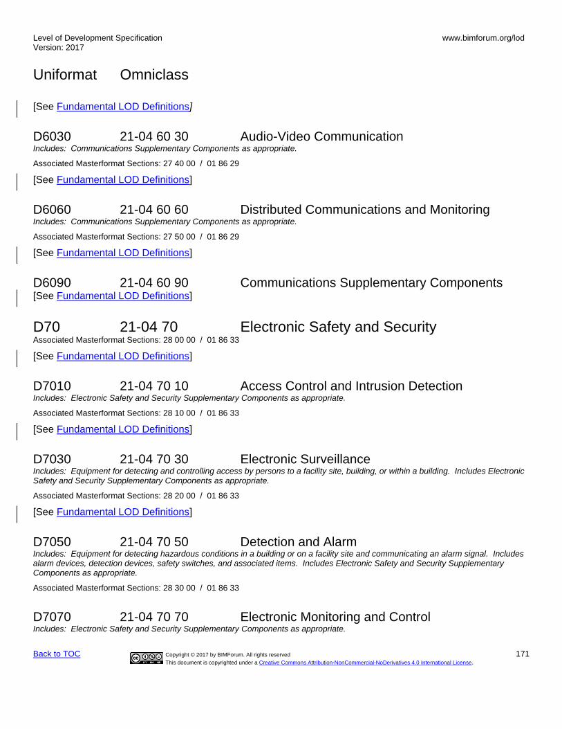
Level of Development Specification Version: 2017
www.bimforum.org/lod
Uniformat Omniclass
Back to TOC Copyright © 2017 by BIMForum. All rights reserved 171
This document is copyrighted under a Creative Commons Attribution-NonCommercial-NoDerivatives 4.0 International License.
[See Fundamental LOD Definitions]
D6030 21-04 60 30 Audio-Video Communication Includes: Communications Supplementary Components as appropriate.
Associated Masterformat Sections: 27 40 00 / 01 86 29
[See Fundamental LOD Definitions]
D6060 21-04 60 60 Distributed Communications and Monitoring Includes: Communications Supplementary Components as appropriate.
Associated Masterformat Sections: 27 50 00 / 01 86 29
[See Fundamental LOD Definitions]
D6090 21-04 60 90 Communications Supplementary Components [See Fundamental LOD Definitions]
D70 21-04 70 Electronic Safety and Security Associated Masterformat Sections: 28 00 00 / 01 86 33
[See Fundamental LOD Definitions]
D7010 21-04 70 10 Access Control and Intrusion Detection Includes: Electronic Safety and Security Supplementary Components as appropriate.
Associated Masterformat Sections: 28 10 00 / 01 86 33
[See Fundamental LOD Definitions]
D7030 21-04 70 30 Electronic Surveillance Includes: Equipment for detecting and controlling access by persons to a facility site, building, or within a building. Includes Electronic Safety and Security Supplementary Components as appropriate.
Associated Masterformat Sections: 28 20 00 / 01 86 33
[See Fundamental LOD Definitions]
D7050 21-04 70 50 Detection and Alarm Includes: Equipment for detecting hazardous conditions in a building or on a facility site and communicating an alarm signal. Includes alarm devices, detection devices, safety switches, and associated items. Includes Electronic Safety and Security Supplementary Components as appropriate.
Associated Masterformat Sections: 28 30 00 / 01 86 33
D7070 21-04 70 70 Electronic Monitoring and Control Includes: Electronic Safety and Security Supplementary Components as appropriate.

Level of Development Specification Version: 2017
www.bimforum.org/lod
Uniformat Omniclass
Back to TOC Copyright © 2017 by BIMForum. All rights reserved 172
This document is copyrighted under a Creative Commons Attribution-NonCommercial-NoDerivatives 4.0 International License.
Associated Masterformat Sections: 28 46 00 / 01 86 33
D7090 21-04 70 90 Electronic Safety and Security Supplementary Components These components are typically modeled as part of other assemblies listed in the tables above. Do not assign this Uniformat classification unless a supplementary component is modeled independently of another assembly.
Associated Masterformat Sections:
D80 21-04 80 Integrated Automation
Associated Masterformat Sections: 25 00 00 / 01 86 23
[See Fundamental LOD Definitions]
D8010 21-04 80 10 Integrated Automation Facility Controls Includes: Hardware and/or software that allows the building automation system to monitor and control other facility equipment and systems. Includes Integrated Automation Supplementary Components as appropriate.
Associated Masterformat Sections: 25 50 00 / 01 86 23
[See Fundamental LOD Definitions]

Level of Development Specification Version: 2017
www.bimforum.org/lod
Uniformat Omniclass
Back to TOC Copyright © 2017 by BIMForum. All rights reserved 173
This document is copyrighted under a Creative Commons Attribution-NonCommercial-NoDerivatives 4.0 International License.
E 21-05 00 00 EQUIPMENT & FURNISHINGS Associated Masterformat Sections: 01 87 00
E10 21-05 10 Equipment Associated Masterformat Sections: 11 00 00 / 01 87 13
100 Diagrammatic or schematic model elements:
conceptual and/or schematic layout;
design performance parameters as defined in the BXP to be associated with model elements as non-graphic information.
E1010 21-05 10 10 Vehicle and Pedestrian Equipment Associated Masterformat Sections: 11 10 00
100 See E10
200 Schematic layout with approximate size, shape, and location of equipment;
design performance parameters as defined in the BXP to be associated with model elements as non-graphic information.
E1010.10 21-05 10 10 10 Vehicle Servicing Equipment Includes: Equipment associated with vehicle service facilities.
Associated Masterformat Sections: 11 11 00 / 11 11 19 / 11 11 23 / 11 11 26
100 See E10
200 See E1010
300 Modeled as design-specified size, shape, spacing, and location of equipment and associated components;
approximate allowances for spacing and clearances required for all specified supports and seismic control;
access/code clearance requirements modeled.
350 Modeled as actual size, shape, spacing, and location of equipment and associated components;
actual size, shape, spacing, and location for supports and seismic control;
actual size, shape, and location of service connections and support structure/pads.
Actual access/code clearance requirements modeled.
400 Supplementary components added to the model required for fabrication and field installation.

Level of Development Specification Version: 2017
www.bimforum.org/lod
Uniformat Omniclass
Back to TOC Copyright © 2017 by BIMForum. All rights reserved 174
This document is copyrighted under a Creative Commons Attribution-NonCommercial-NoDerivatives 4.0 International License.
E1010.30 21-05 10 10 30 Interior Parking Control Equipment Includes: Equipment associated with the control of movement of vehicle parking.
Associated Masterformat Sections: 11 12 00 / 11 12 13 / 11 12 16 / 11 12 23 / 11 12 26 / 11 12 33
[See E1010.10]
E1010.50 21-05 10 10 50 Loading Dock Equipment Includes: Equipment for the protection of service docks and for the loading and unloading of service vehicles.
Associated Masterformat Sections: 11 13 00 / 11 13 13 / 11 13 16 / 11 13 19.13 / 11 13 19.23 / 11 13 26
[See E1010.10]
E1010.70 21-05 10 10 70 Interior Pedestrian Control Equipment Includes: Equipment associated with the control of movement of pedestrians.
Associated Masterformat Sections: 11 14 00 / 11 14 13 / 11 14 16 / 11 14 26 / 11 14 43 / 11 14 53
[See E1010.10]
E1030 21-05 10 30 Commercial Equipment Associated Masterformat Sections: 11 20 00
[See E1010]
E1030.10 21-05 10 30 10 Mercantile and Service Equipment Includes: Equipment used in retail and service stores.
Associated Masterformat Sections: 11 21 00 / 11 21 13 / 11 21 23 / 11 21 33 / 11 21 43 / 11 21 53
[See E1010.10]
E1030.20 21-05 10 30 20 Vault Equipment Includes: Equipment specifically designed for money or valuable material storage, including vault ventilators and specialized security equipment.
Associated Masterformat Sections: 11 16 00 / 11 16 13 / 11 16 16 / 11 16 23
[See E1010.10]
E1030.25 21-05 10 30 25 Teller and Service Equipment Includes: Equipment specifically designed for handling and transfer of money and other high-security items.
Associated Masterformat Sections: 11 17 00 / 11 17 13 / 11 17 16 / 11 17 23 / 11 17 33 / 11 17 36
[See E1010.10]

Level of Development Specification Version: 2017
www.bimforum.org/lod
Uniformat Omniclass
Back to TOC Copyright © 2017 by BIMForum. All rights reserved 175
This document is copyrighted under a Creative Commons Attribution-NonCommercial-NoDerivatives 4.0 International License.
E1030.30 21-05 10 30 30 Refrigerated Display Equipment Includes: Display cases that include refrigeration.
Associated Masterformat Sections: 11 22 00
[See E1010.10]
E1030.35 21-05 10 30 35 Commercial Laundry and Dry Cleaning Equipment Includes: Equipment for commercial laundry and dry-cleaning operations including coin-operated equipment.
Associated Masterformat Sections: 11 23 00 / 11 23 13 / 11 23 16 / 11 23 19 / 11 23 23 / 11 23 26 / 11 23 33 / 11 23 43
[See E1010.10]
E1030.40 Maintenance Equipment Includes: Built-in and free-standing equipment for building maintenance.
Associated Masterformat Sections: 11 24 00 / 11 24 13 / 11 24 16 / 11 24 19 / 11 24 23.13
[See E1010.10]
E1030.50 21-05 10 30 50 Hospitality Equipment Includes: Specialized equipment for the purpose of registering, admitting, and controlling rooms and other information at hotels, motels, hospitals, and other similar facilities.
Associated Masterformat Sections: 11 25 00 / 11 25 13
[See E1010.10]
E1030.55 21-05 10 30 55 Unit Kitchens Includes: Manufactured units incorporating plumbing fixtures, appliances, casework and countertops.
Associated Masterformat Sections: 11 26 00
[See E1010.10]
E1030.60 21-05 10 30 60 Photographic Processing Equipment Includes: Photographic film processing equipment and other products for darkroom use.
Associated Masterformat Sections: 11 27 00 / 11 27 13 / 11 27 16
[See E1010.10]
E1030.70 21-05 10 30 70 Postal, Packaging and Shipping Equipment Includes: Equipment for normal mailing, packaging, shipping, and delivery operations for professional, commercial, and institutional applications.
Associated Masterformat Sections: 11 29 00 / 11 29 23 / 11 29 33 / 11 29 55 / 11 28 23
[See E1010.10]

Level of Development Specification Version: 2017
www.bimforum.org/lod
Uniformat Omniclass
Back to TOC Copyright © 2017 by BIMForum. All rights reserved 176
This document is copyrighted under a Creative Commons Attribution-NonCommercial-NoDerivatives 4.0 International License.
E1030.75 21-05 10 30 75 Office Equipment Includes: Computers, printers, copiers, drafting equipment, plotters, carto-stereographs, and other equipment used in offices.
Associated Masterformat Sections: 11 28 00 / 11 28 13 / 11 28 16 / 11 28 19 / 11 28 23
[See E1010.10]
E1030.80 21-05 10 30 80 Foodservice Equipment Includes: Equipment used for liquid and solid food storage, preparation, display, serving, and clean-up in commercial and institutional kitchens and bars.
Associated Masterformat Sections: 11 40 00 / 11 41 00 / 11 41 13 / 11 41 23 / 11 41 26 / 11 41 33 / 11 42 00 / 11 43 00 / 11 41 13 / 11 41 16 / 11 44 00 / 11 44 13 / 11 44 16 / 11 46 00 / 11 46 13 / 11 46 16 / 11 46 19 / 11 47 00 / 11 48 00 / 11 48 13
[See E1010.10]
E1040 21-05 10 40 Institutional Equipment Associated Masterformat Sections: 11 50 00
[See E1010]
E1040.10 21-05 10 40 10 Educational and Scientific Equipment Includes: Equipment associated with libraries, education facilities, laboratories, planetariums, observatories, and museums.
Associated Masterformat Sections: 11 50 00 / 11 51 00 / 11 51 13 / 11 51 16 / 11 51 19 / 11 51 23 / 11 52 00 / 11 52 13 / 11 52 16 / 11 52 19 / 11 53 00 / 11 53 13 / 11 53 16 / 11 53 19 / 11 53 23 / 11 53 33 / 11 53 43 / 11 53 53 / 11 55 00 / 11 55 13 / 11 55 16 / 11 56 00 / 11 56 13 / 11 57 00 / 11 59 00 / 11 95 00 / 11 95 13
[See E1010.10]
E1040.20 21-05 10 40 20 Healthcare Equipment Includes: Specialized equipment for healthcare facilities for humans and animals. Includes film illuminators, fluoroscopes, hubbard tubs, radio isotopic equipment, and surgical equipment.
Associated Masterformat Sections: 11 70 00 / 05 45 23 / 11 71 00 / 11 72 00 / 11 73 00 / 11 74 00 / 11 75 00 / 11 76 00 / 11 77 00 / 11 78 00 / 11 78 13 / 11 78 16 / 11 78 19 / 11 79 00
[See E1010.10]
E1040.40 21-05 10 40 40 Religious Equipment Includes: Built-in and free-standing religious equipment, including baptistery and chancel fittings.
Associated Masterformat Sections: 11 91 00 / 11 91 13
[See E1010.10]
E1040.60 21-05 10 40 60 Security Equipment Includes: Equipment specifically designed for secure operations.
Associated Masterformat Sections: 11 18 00 / 11 18 13 / 11 18 16 / 11 18 23

Level of Development Specification Version: 2017
www.bimforum.org/lod
Uniformat Omniclass
Back to TOC Copyright © 2017 by BIMForum. All rights reserved 177
This document is copyrighted under a Creative Commons Attribution-NonCommercial-NoDerivatives 4.0 International License.
[See E1010.10]
E1040.70 21-05 10 40 70 Detention Equipment Includes: Equipment specifically designed for detention facilities.
Associated Masterformat Sections: 11 19 00 / 01 87 13 / 11 19 13 / 11 19 16
[See E1010.10]
E1060 21-05 10 60 Residential Equipment Includes: Built-in and free-standing appliances and other components specifically for residential use.
Associated Masterformat Sections: 11 30 00
[See E1010]
E1060.10 21-05 10 60 10 Residential Appliances
Associated Masterformat Sections: 11 31 00 / 11 31 13 / 11 31 23
[See E1010.10]
E1060.50 21-05 10 60 50 Residential Stairs
Associated Masterformat Sections: 11 33 00
[See B1080]
E1060.70 21-05 10 60 70 Residential Ceiling Fans
Associated Masterformat Sections: 11 34 00
[See E1010.10]
E1070 21-05 10 70 Entertainment and Recreational Equipment Includes: Equipment for use in athletic, recreational, and therapeutic activities.
Associated Masterformat Sections:
[See E1010]
E1070.10 21-05 10 70 10 Theater and Stage Equipment Includes: Equipment for support of theatrical, instrumental, and voice programs. Includes cycloramas, entertainment ticket dispensers, scenery and flats, and tormentors.
Associated Masterformat Sections: 11 61 00 / 11 61 13 / 11 61 23 / 11 61 33 / 11 61 43
[See E1010.10]
E1070.20 21-05 10 70 20 Musical Equipment Includes: Musical instruments, including prefabricated and field assembled instruments. Associated Masterformat Sections: 11 62 00 / 11 62 13 / 11 62 16 / 11 62 19
[See E1010.10]
Level of Development Specification Version: 2017
www.bimforum.org/lod
Uniformat Omniclass
Back to TOC Copyright © 2017 by BIMForum. All rights reserved 178
This document is copyrighted under a Creative Commons Attribution-NonCommercial-NoDerivatives 4.0 International License.
E1070.50 21-05 10 70 50 Athletic Equipment Includes: Equipment for use in interior athletic and exercise activities.
Associated Masterformat Sections: 11 66 00 / 11 66 13 / 11 66 23 / 11 66 43 / 11 66 53
[See E1010.10]
E1070.60 21-05 10 70 60 Recreational Equipment Includes: Equipment for use in recreational activities. Includes curling rinks and pistol and rifle range equipment.
Associated Masterformat Sections: 11 67 00 / 11 67 13 / 11 67 23 / 11 67 33 / 11 67 43 / 11 67 53
[See E1010.10]
E1090 21-05 10 90 Other Equipment Associated Masterformat Sections: 11 90 00
[See E1010]
E1090.10 21-05 10 90 10 Solid Waste Handling Equipment Includes: Equipment involving the collection, shredding, compaction, removal and incineration of trash and other solid waste
Associated Masterformat Sections: 11 82 00 / 01 87 13 / 11 82 13 / 11 82 19 / 11 82 23 / 11 82 26 / 11 82 29 / 11 82 33 / 11 82 36 [See E1010.10]
E1090.30 21-05 10 90 30 Agricultural Equipment Includes: Equipment related to land cultivating, raising crops, and feeding, breeding, and raising of livestock.
Associated Masterformat Sections: 11 92 00 / 11 92 13 / 11 92 16 / 11 92 19 / 11 92 23
[See E1010.10]
E1090.40 21-05 10 90 40 Horticultural Equipment Includes: Equipment related to cultivating flowers, fruits, vegetables, or ornamental plants.
Associated Masterformat Sections: 11 93 00 / 11 93 13 / 11 93 16 / 11 93 19 / 11 93 23 / 11 93 26 / 11 93 29 / 11 93 33 / 32 86 00
[See E1010.10]
E1090.60 21-05 10 90 60 Decontamination Equipment Includes: Equipment associated with decontamination operations.
Associated Masterformat Sections:
[See E1010.10]
E20 21-05 20 Furnishings Associated Masterformat Sections: 12 00 00 / 01 87 16

Level of Development Specification Version: 2017
www.bimforum.org/lod
Uniformat Omniclass
Back to TOC Copyright © 2017 by BIMForum. All rights reserved 179
This document is copyrighted under a Creative Commons Attribution-NonCommercial-NoDerivatives 4.0 International License.
100 A schematic model element or symbol that is not distinguishable by type or material.
Types, layouts, and locations are still flexible.
E2010 21-05 20 10 Fixed Furnishings Associated Masterformat Sections:
100 See E20
200 Generic model elements with approximate nominal size.
Placement and quantity remains flexible.
•
E2010.10 21-05 20 10 10 Fixed Art Includes: Interior and exterior fixed art objects.
Associated Masterformat Sections: 12 10 00 / 12 11 00 / 12 12 00 / 12 12 23 / 12 12 26 / 12 14 00 / 12 17 00 / 12 19 00
100 See E20
200 See E2010
300 Modeled types with specific dimensions, locations, and quantities.
350 Include any applicable service or installation clearances.
Include any applicable support and connection points.
400 Supplementary components added to the model required for fabrication and field installation.
E2010.20 21-05 20 10 20 Window Treatments Includes: Interior window coverings and associated hardware and controls.
Associated Masterformat Sections: 12 20 00 / 12 21 00 / 12 22 00 / 12 23 00 / 12 24 00 / 12 25 00
[See E2010.10]
E2010.30 21-05 20 10 30 Casework Includes: Custom and manufactured stock design steel, wood, and laminate faced cabinets and other casework units. Includes countertops with integral sinks, fixtures and accessories.
Associated Masterformat Sections: 12 30 00 / 12 35 00 / 12 35 17 / 12 35 25 / 12 35 30 / 12 35 33 / 12 35 50 / 12 35 53 / 12 35 59 / 12 35 70 / 12 35 91 / 12 36 00
[See E2010.10]
Level of Development Specification Version: 2017
www.bimforum.org/lod
Uniformat Omniclass
Back to TOC Copyright © 2017 by BIMForum. All rights reserved 180
This document is copyrighted under a Creative Commons Attribution-NonCommercial-NoDerivatives 4.0 International License.
E2010.70 21-05 20 10 70 Fixed Multiple Seating Includes: Fixed, and telescoping seating for theaters, auditoriums, lecture halls, stadiums, arenas, gymnasiums, religious buildings, restaurants, and other facilities where multiple seating is required.
Associated Masterformat Sections: 12 60 00 / 12 61 00 / 12 63 00 / 13 34 16.53 / 12 64 00 / 12 65 00 / 12 66 00 / 12 67 00 / 12 68 00
[See E2010.10]
E2010.90 21-05 20 10 90 Other Fixed Furnishings Includes: Fixed artificial plants, planters, and accessories.
Associated Masterformat Sections: 12 90 00 / 12 92 00 / 12 92 13 / 12 92 33 / 12 92 43
[See E2010.10]
E2050 21-05 20 50 Movable Furnishings Includes: Items of moveable furniture and furnishing accessories. Includes furniture for a variety of uses including classroom, dormitory, ecclesiastical, hotel and motel, laboratory, library, lounge, medical, office, restaurant, and residential. Associated Masterformat Sections:
[See E2010]
E2050.10 21-05 20 50 10 Movable Art Includes: Interior and exterior moveable art objects such as paintings, and sculpture. Associated Masterformat Sections: 12 10 00 / 12 14 00 / 12 19 00
[See E2010.10]
E2050.30 21-05 20 50 30 Furniture Includes: Movable interior furniture. Associated Masterformat Sections: 12 50 00 / 12 51 00 / 12 52 00 / 12 52 23 / 12 52 70 / 12 53 00 / 12 54 00 / 12 54 13 / 12 54 16 / 12 55 00 / 12 56 00 / 12 56 33 / 12 56 39 / 12 56 43 / 12 56 51 / 12 56 52 / 12 56 53 / 12 56 70 / 12 57 00 / 12 57 13 / 12 57 16 / 12 58 00 / 12 59 00
[See E2010.10]
E2050.40 21-05 20 50 40 Accessories Includes: Interior furnishing accessories not attached to permanent construction. Associated Masterformat Sections: 12 40 00 / 12 41 00 / 12 42 00 / 12 43 00 / 12 44 00 / 12 44 16 / 12 45 00 / 12 46 00 / 12 48 00
[See E2010.10]
E2050.60 21-05 20 50 60 Movable Multiple Seating Includes: Portable seating for auditoriums, lecture halls, stadiums, arenas, gymnasiums, religious buildings, restaurants, and other facilities where multiple seating is required. Associated Masterformat Sections: 12 60 00 / 12 62 00 / 12 65 00 / 12 67 00 / 12 68 00
[See E2010.10]

Level of Development Specification Version: 2017
www.bimforum.org/lod
Uniformat Omniclass
Back to TOC Copyright © 2017 by BIMForum. All rights reserved 181
This document is copyrighted under a Creative Commons Attribution-NonCommercial-NoDerivatives 4.0 International License.
E2050.90 21-05 20 50 90 Other Movable Furnishings Includes: Moveable artificial plants, and planters. Associated Masterformat Sections: 12 90 00 / 12 92 00 / 12 92 13 / 12 92 33 / 12 92 43
[See E2010.10]
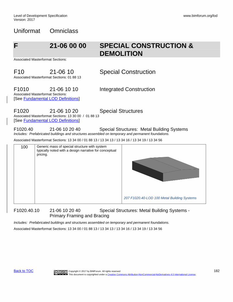
Level of Development Specification Version: 2017
www.bimforum.org/lod
Uniformat Omniclass
Back to TOC Copyright © 2017 by BIMForum. All rights reserved 182
This document is copyrighted under a Creative Commons Attribution-NonCommercial-NoDerivatives 4.0 International License.
F 21-06 00 00 SPECIAL CONSTRUCTION & DEMOLITION Associated Masterformat Sections:
F10 21-06 10 Special Construction Associated Masterformat Sections: 01 88 13
F1010 21-06 10 10 Integrated Construction Associated Masterformat Sections: [See Fundamental LOD Definitions]
F1020 21-06 10 20 Special Structures Associated Masterformat Sections: 13 30 00 / 01 88 13
[See Fundamental LOD Definitions]
F1020.40 21-06 10 20 40 Special Structures: Metal Building Systems Includes: Prefabricated buildings and structures assembled on temporary and permanent foundations.
Associated Masterformat Sections: 13 34 00 / 01 88 13 / 13 34 13 / 13 34 16 / 13 34 19 / 13 34 56
100 Generic mass of special structure with system typically noted with a design narrative for conceptual pricing.
207 F1020.40-LOD 100 Metal Building Systems
F1020.40.10 21-06 10 20 40 Special Structures: Metal Building Systems - Primary Framing and Bracing
Includes: Prefabricated buildings and structures assembled on temporary and permanent foundations.
Associated Masterformat Sections: 13 34 00 / 01 88 13 / 13 34 13 / 13 34 16 / 13 34 19 / 13 34 56

Level of Development Specification Version: 2017
www.bimforum.org/lod
Uniformat Omniclass
Back to TOC Copyright © 2017 by BIMForum. All rights reserved 183
This document is copyrighted under a Creative Commons Attribution-NonCommercial-NoDerivatives 4.0 International License.
200 Generic mass of frame shown in an approximate location, and a general span/direction with a design narrative for conceptual pricing.
Model elements to include:
• Framing grids defined.
• Sections shapes shown but profiles, tapers and plate thicknesses and flange widths still flexible.
• Primary braced bay locations
• End wall framing type (i.e., main frame versus post and beam)
Crane runways
208 F1020.40-LOD 200 Metal Building Systems - Primary Framing
300 Metal Building System components including:
1) Endwall or wind column 2) End frame main members 3) Module or interior columns 4) Frames and main members
a. Columns b. Rafters
5) Roof and wall diagonal bracing 6) Crane beams
Element modeling to include:
• Specific sizes of frame structural members, all with correct orientation
• Web tapers
• Frame connection type (Extended/Flush)
• Any lateral bracing components connecting to frame or foundation (i.e., portal frames, fixed base columns, diagonal bracing - rods or cables, struts) all with specific sizes and orientation.
209 F1020.40-LOD 300 Metal Building Systems - Primary Framing

Level of Development Specification Version: 2017
www.bimforum.org/lod
Uniformat Omniclass
Back to TOC Copyright © 2017 by BIMForum. All rights reserved 184
This document is copyrighted under a Creative Commons Attribution-NonCommercial-NoDerivatives 4.0 International License.
350 Element modeling to include:
• Base plate locations
• Bracing components (i.e. gussets)
• Critical or large elements of connections applied to all structural steel connections such as base plates, gusset plates, anchor rods, etc.
• Clips required for connection to secondary framing
• Any miscellaneous steel members with correct size, shape, orientation and material required for the frame structure. (i.e., roof beams, spandrels)
• Any steel structure reinforcement such as web stiffeners, connection plate stiffeners, sleeve penetrations, etc. required for coordination.
210 F1020.40-LOD 350 Metal Building Systems - Primary Framing

Level of Development Specification Version: 2017
www.bimforum.org/lod
Uniformat Omniclass
Back to TOC Copyright © 2017 by BIMForum. All rights reserved 185
This document is copyrighted under a Creative Commons Attribution-NonCommercial-NoDerivatives 4.0 International License.
400 Element modeling to include fabrication level information:
• Welds
• Reinforcement plates
• Coping of members
• Bolts, nuts, washers, etc.
• Holes, slots, etc., including holes for future element attachments
• All assembly elements
211 F1020.40-LOD 400 Metal Building Systems - Primary Framing
F1020.40.20 21-06 10 20 40 Special Structures: Metal Building Systems - Secondary Framing
Includes: Prefabricated buildings and structures assembled on temporary and permanent foundations.
Associated Masterformat Sections: 13 34 00 / 01 88 13 / 13 34 13 / 13 34 16 / 13 34 19 / 13 34 56

Level of Development Specification Version: 2017
www.bimforum.org/lod
Uniformat Omniclass
Back to TOC Copyright © 2017 by BIMForum. All rights reserved 186
This document is copyrighted under a Creative Commons Attribution-NonCommercial-NoDerivatives 4.0 International License.
200 Generic mass of special structure with system typically noted with a design narrative for conceptual pricing. Generic open wall conditions identified (i.e., open for material by others, open for passage, etc.)
Approximate overall depth and extent represented by secondary roof and wall framing members.
300 Metal Building System components, including:
• Purlins and bridging
• Eave strut
• Sidewall girts
• Endwall girts
• Sag braces
• Framed openings (jambs, headers, etc.)
• Window sub-frames
• Walk door sub-frames
• Wall member connection type (Flush/Bypass/Inset)
• Base condition (i.e., angle, channel, tube)
Element modeling to include:
• Specific sizes of main structural members, (mass for open web members), all with correct orientation
213 F1020.40-LOD 300 Metal Building Systems - Secondary Framing
212 F1020.40-LOD 200 Metal Building Systems - Secondary Framing

Level of Development Specification Version: 2017
www.bimforum.org/lod
Uniformat Omniclass
Back to TOC Copyright © 2017 by BIMForum. All rights reserved 187
This document is copyrighted under a Creative Commons Attribution-NonCommercial-NoDerivatives 4.0 International License.
350 Element modeling to include:
• Nested members
• Connections for member bracing
• Clips joining secondary framing members
• Large elements of typical connections applied to all secondary steel connections such as girt to column, purlin to rafter, jamb to girt, header to jamb, etc.
• Secondary angles, including sheeting angles and rake angles
• Base attachment members
• Any miscellaneous secondary steel members with correct orientation, i.e. canopies, parapets, door framing, etc.
• Web members and bridging for open web purlins
• For bar joist, see Steel Open Web Joists LOD.
214 F1020.40-LOD 350 Metal Building Systems- Secondary Framing
400 Element modeling to include fabrication level information:
• Welds
• Bolts, nuts, washers, screws, and fasteners
• Coping of members
• Holes cut for bracing
• Nested member attachments
• All assembly elements
• Continuous web vs. open web
215 F1020.40-LOD 400 Metal Building Systems - Secondary Framing
F1020.40.30 21-06 10 20 40 Special Structures: Metal Building Systems - Cladding and Exterior Trim Includes: Prefabricated buildings and structures assembled on temporary and permanent foundations.
Associated Masterformat Sections: 13 34 00 / 01 88 13 / 13 34 13 / 13 34 16 / 13 34 19 / 13 34 56

Level of Development Specification Version: 2017
www.bimforum.org/lod
Uniformat Omniclass
Back to TOC Copyright © 2017 by BIMForum. All rights reserved 188
This document is copyrighted under a Creative Commons Attribution-NonCommercial-NoDerivatives 4.0 International License.
200 Element modeling to include:
1) Panel: a. Generic mass of panel with a
generic profile or graphical texture shown,
b. Openings/Voids are represented, identifying cladding boundaries within the wall/roof plane.
2) Trim: a. Major exterior trim used to separate
roof and walls and trim used for aesthetic accent, represented by a generic trim profile.
216 F1020.40-LOD 200 Metal Building Systems –Cladding and Exterior Trim
300 Element modeling to include:
• Panel: o Panel with actual profile or graphical
texture shown, filling the boundary set by the plane object.
o Significant accessories (i.e., light transmitting panels, ridge vents, curbs) shown
o Openings/Voids are represented in true dimensions/locations.
• Trim: o Major trims (primary exterior pieces)
are shown, represented by the actual trim profile, thickness, and color.
▪ Gutters ▪ Corner boxes ▪ Corners ▪ Open wall trim ▪ Framed opening trim
217 F1020.40-LOD 300 Metal Building Systems –Cladding and Exterior Trim

Level of Development Specification Version: 2017
www.bimforum.org/lod
Uniformat Omniclass
Back to TOC Copyright © 2017 by BIMForum. All rights reserved 189
This document is copyrighted under a Creative Commons Attribution-NonCommercial-NoDerivatives 4.0 International License.
350 Element modeling to include:
• Panel: o Actual profile modeled filling the
boundary set by the plane object. o Closures o Downspouts
• Trim: o Minor trims (end caps, transition
pieces, etc.) are shown generically.
Other non-graphic information may be included such as: Textual information on installation details
218 F1020.40-LOD 350 Metal Building Systems –Cladding and Exterior Trim
F1020.40-LOD 350 Metal Building Systems –Cladding and Exterior Trim

Level of Development Specification Version: 2017
www.bimforum.org/lod
Uniformat Omniclass
Back to TOC Copyright © 2017 by BIMForum. All rights reserved 190
This document is copyrighted under a Creative Commons Attribution-NonCommercial-NoDerivatives 4.0 International License.
400 Element modeling to include fabrication level information:
• Panel: o Individual panel objects, with actual
profile shown, positioned accurately within the building plane boundary and shown at installed length.
o Fasteners at critical locations o Closures o Cinch straps o Caulk/mastic and other field-
installed weather-tightness materials shown at critical locations
• Trim: o Minor trims (end caps, transition
pieces, etc.) are shown accurately. o Attachment or accessories
(fasteners, etc.) shown at critical locations.
o Caulk/mastic and other field-installed weather-tightness materials shown at critical locations
Other non-graphic information may be included such as: Additional material and its installation instructions required for proper installation Mark identification that correlates with bill of material (i.e., piece mark) Fastener material and installation instructions Caulk/mastic and other field-installed weather-tightness materials and installation instructions
F1030 21-06 10 30 Special Function Construction Associated Masterformat Sections: [See Fundamental LOD Definitions]
F1050 21-06 10 50 Special Facility Components Associated Masterformat Sections: [See Fundamental LOD Definitions]
F1060 21-06 10 60 Athletic and Recreational Special Construction Includes: Special construction for athletic and recreational activities that are directly related to the adjacent construction.
Associated Masterformat Sections: 13 28 00
[See Fundamental LOD Definitions]
Level of Development Specification Version: 2017
www.bimforum.org/lod
Uniformat Omniclass
Back to TOC Copyright © 2017 by BIMForum. All rights reserved 191
This document is copyrighted under a Creative Commons Attribution-NonCommercial-NoDerivatives 4.0 International License.
F1080 21-06 10 80 Special Instrumentation Includes: Instrumentation for measuring and recording phenomena such as stresses in structures, solar and wind energy, and effects of earthquakes.
Associated Masterformat Sections: 13 50 00
[See Fundamental LOD Definitions]
F20 21-06 20 Facility Remediation Associated Masterformat Sections:
F2010 21-06 20 10 Hazardous Materials Remediation Includes: Remediation for abatement and removal and disposal of contaminated materials within structures.
Associated Masterformat Sections: 02 80 00
[See Fundamental LOD Definitions]
F30 21-06 30 Demolition Associated Masterformat Sections:
F3010 21-06 30 10 Structure Demolition Includes: Complete removal and disposal of structures.
Associated Masterformat Sections: 02 41 16
[See Fundamental LOD Definitions]
F3030 21-06 30 30 Selective Demolition Includes: Removal and disposal of parts of structures.
Associated Masterformat Sections: 02 41 19
[See Fundamental LOD Definitions]
F3050 21-06 30 50 Structure Moving Includes: Preparation and processes of relocating and raising structures.
Associated Masterformat Sections: 02 43 00
[See Fundamental LOD Definitions]
G 21-07 00 00 BUILDING SITEWORK
Associated Masterformat Sections: 01 89 00
G10 21-07 10 Site Preparation Associated Masterformat Sections: 01 89 13

Level of Development Specification Version: 2017
www.bimforum.org/lod
Uniformat Omniclass
Back to TOC Copyright © 2017 by BIMForum. All rights reserved 192
This document is copyrighted under a Creative Commons Attribution-NonCommercial-NoDerivatives 4.0 International License.
100 A simple topographic surface is provided.
219 G10-LOD-100 Site Preparation
200 Element modeling to include:
• Approximate size and shape of foundation element
• Approximate size/location of utilities and structures
• Approximate code and clearance requirements
• Approximate pipe material
• Rough modeling of site grading
G1010 21-07 10 10 Site Clearing Includes: Removal of vegetation from the site, including stripping of sod and soil, and tree pruning for site clearing.
Associated Masterformat Sections: 31 10 00 / 31 11 00 / 31 13 00 / 31 14 00 / 31 14 13 / 31 14 16
G1020 21-07 10 20 Site Elements Demolition Includes: Removal of above and below grade site improvements.
Associated Masterformat Sections: 02 41 13
G1030 21-07 10 30 Site Element Relocations Includes: Relocation of utility systems.
G1050 21-07 10 50 Site Remediation Includes: Remediation of contaminated sites.
Associated Masterformat Sections: 02 50 00 / 01 89
G1070 21-07 10 70 Site Earthwork Includes: Moving earth to establish new contours and elevations.
Associated Masterformat Sections: 31 20 00 / 01 89 13
G1070.10 21-07 10 70 10 Grading Includes: Earthmoving to reshape contours.
Associated Masterformat Sections: 31 20 00 / 01 89 13

Level of Development Specification Version: 2017
www.bimforum.org/lod
Uniformat Omniclass
Back to TOC Copyright © 2017 by BIMForum. All rights reserved 193
This document is copyrighted under a Creative Commons Attribution-NonCommercial-NoDerivatives 4.0 International License.
100 Proposed Surfaces shown as a plane.
200 Proposed Surface: Generic Surface Interpolation between the following elements: Building Envelope at Finish Floor, Finish Grade at Retaining Walls, Grading Limits. Curbs, hardscape, finish surface at building envelopes.
300 Proposed Surface: Complete and accurate surface definition based on defined fine grading, grade breaks, curbs, hardscape, buildings, swales, etc.
Local Coordinate Control. Shared Coordinate from Building Grid base point to real-world project control
350 Include existing Surface: 3D surface generated from site topography, with grade breaks and lines as needed to define accurate surface. 3D site features included if provided by surveyor (i.e. walls, signage, stairs, etc., as defined in Survey LOC-Grade). Added definition from supplemental survey, revised limits of work
400 Surface modeled to facilitate robotic controlled grading and GPS grade-control systems.
G20 21-07 20 Site Improvements Associated Masterformat Sections: 01 89 16
100 Diagrammatic or schematic model elements.

Level of Development Specification Version: 2017
www.bimforum.org/lod
Uniformat Omniclass
Back to TOC Copyright © 2017 by BIMForum. All rights reserved 194
This document is copyrighted under a Creative Commons Attribution-NonCommercial-NoDerivatives 4.0 International License.
200 Element modeling to include:
• Approximate size and shape of foundation element
• Approximate size/location of utilities and structures
• Approximate code and clearance requirements
• Rough modeling of site grading
• Local structural building grids defined in model and coordinated with global state plane coordinate system for site model.
G2010 21-07 20 10 Roadways Includes: Pavement, curbs and gutters, appurtenances, lighting, and vehicle fare collection for roadways.May Include: Site earthwork.
Associated Masterformat Sections: 01 89 16
[See Fundamental LOD Definitions]
G2020 21-07 20 20 Parking Lots Includes: Pavement, curbs and gutters, appurtenances, lighting, and parking control equipment for parking lots.May Include: Site earthwork
Associated Masterformat Sections: 01 89 16
[See Fundamental LOD Definitions]
G2020.10 21-07 20 20 10 Parking Lot Pavement Includes: Prepared and compacted soil and granular layers placed prior to installation of parking lot pavement. Includes: Finished parking lot pavement of granular and asphaltic materials. Includes: Finished parking lot pavement with high bending resistance, usually of concrete. Includes: Blocks or tiles used for parking lot pavement. Unit pavers set in mastic, sand, or mortar.
Associated Masterformat Sections: 32 10 00 / 32 12 00 / 32 13 00 / 32 14 00 / 32 15 00
100 See G20 200 See G20 300 Specific thickness of pavement and substrate modeled.
All drainage slopes modeled.
350 Openings for drains and other services modeled.
G2020.20 21-07 20 20 20 Parking Lot Curbs and Gutters Includes: Construction at perimeter of parking lot pavement to separate pavement from adjacent surfaces, provide vehicular restraint, and facilitate drainage.
Associated Masterformat Sections: 32 16 13
100 See G20
200 See G20
300 Full extents of curbs and gutters (above and below grade) are modeled.
350 Element modeling to include:
• Reinforcing
• Pour stops
• Expansion joints

Level of Development Specification Version: 2017
www.bimforum.org/lod
Uniformat Omniclass
Back to TOC Copyright © 2017 by BIMForum. All rights reserved 195
This document is copyrighted under a Creative Commons Attribution-NonCommercial-NoDerivatives 4.0 International License.
G2020.40 21-07 20 20 40 Parking Lot Appurtenances Includes traffic signals, signage, striping.
Associated Masterformat Sections: 32 17 00 / 32 17 13 / 32 17 43 / 10 14 53 / 32 17 23
G2030 21-07 20 30 Pedestrian Plazas and Walkways Includes: Pavement, curbs and gutters, appurtenances, lighting, and pedestrian control equipment for pedestrian plazas and walkways. Includes exterior steps and ramps. May Include: Site earthwork.
Associated Masterformat Sections: 01 89 16
G2040 21-07 20 40 Airfields Includes: Pavement, curbs and gutters, appurtenances, lighting, and airfield signally and control equipment for airfields.May Include: Site earthwork.
Associated Masterformat Sections: 01 89 16
G2050 21-07 20 50 Athletic, Recreational, and Playfield Areas Includes: Surfacing, fencing, equipment, grandstands and bleachers, and lighting for athletic, recreational, and playfield areas. May Include: Site earthwork.
Associated Masterformat Sections: 01 89 16
G2060 21-07 20 60 Site Development [See Fundamental LOD Definitions]
G2080 21-07 20 80 Landscaping [See Fundamental LOD Definitions]
Includes: Trees
Associated Masterformat Sections: 31 20 00 / 01 89 13
G30 21-07 30 Liquid and Gas Site Utilities Associated Masterformat Sections: 01 89 19
100 Narrative that references the grading model 200 Approximate sizes, vertical control, and apparatus.

Level of Development Specification Version: 2017
www.bimforum.org/lod
Uniformat Omniclass
Back to TOC Copyright © 2017 by BIMForum. All rights reserved 196
This document is copyrighted under a Creative Commons Attribution-NonCommercial-NoDerivatives 4.0 International License.
G3010 21-07 30 10 Water Utilities Includes: Water distribution for domestic consumption, fire fighting, and irrigation for a facility site and for multiple facilities. Includes trenching and backfilling. Includes Liquid and Gas Site Utilities Supplementary Components as appropriate.
Associated Masterformat Sections: 33 10 00
100 See G30 200 See G30
G3010.10 21-07 30 10 10 Site Domestic Water Distribution Includes: Supply wells, piping, equipment, storage tanks, and water ponds and reservoirs.
Associated Masterformat Sections: 01 89 19 / 33 21 00 / 33 11 00 / 33 12 00 / 33 12 13 33 12 16 / 33 12 19 / 33 12 23 / 33 12 33 / 33 13 00 / 33 16 00 / 33 47 19.13 / 33 47 13.13 33 47 16.13
100 See G30 200 See G30
G3010.30 21-07 30 10 30 Site Fire Protection Water Distribution Includes: Supply wells, piping, equipment, storage tanks, and water ponds and reservoirs.
Associated Masterformat Sections: 01 89 19 / 33 21 00 / 33 11 19 / 33 12 00 / 33 12 13 / 33 12 16 / 33 12 19 / 33 12 23 / 33 12 33 / 33 16 00 / 33 47 19.33 / 33 47 13.13 / 33 47 16.13
100 See G30
200 See G30
G3020 21-07 30 20 Sanitary Sewerage Utilities Includes: Sanitary sewerage for a facility site and for multiple facilities. Includes piping, septic tanks that serve multiple facilities, structures, and lagoons. Includes trenching and backfilling. Includes Liquid and Gas Site Utilities Supplementary Components as appropriate.
Associated Masterformat Sections: 33 30 00 / 01 89 19
100 See G30 200 See G30
G3020.20 21-07 30 20 20 Sanitary Sewerage Piping Associated Masterformat Sections: 33 31 00 / 33 33 00 / 33 34 00
100 See G30 200 See G30
300 Specific elevations, sizes, materials

Level of Development Specification Version: 2017
www.bimforum.org/lod
Uniformat Omniclass
Back to TOC Copyright © 2017 by BIMForum. All rights reserved 197
This document is copyrighted under a Creative Commons Attribution-NonCommercial-NoDerivatives 4.0 International License.
G3020.50 21-07 30 20 50 Sanitary Sewerage Structures Associated Masterformat Sections: 33 39 00 / 33 39 13 / 33 39 23
100 See G30 200 Approximate structure types, sizes and materials
300 Specific structure elements at all locations, specific sizes and materials
G3030 21-07 30 30 Storm Drainage Utilities Includes: Storm drainage for surface or combination of surface and subsurface water for a facility site or for multiple facilities.Includes piping, culverts, water drains, drainage pumps, Subdrainage, and storm drainage ponds and reservoirs. Includes trenching and backfilling. Includes Liquid and Gas Site Utilities Supplementary Components as appropriate.
Associated Masterformat Sections: 01 89 19
100 See G30 200 See G30
G3050 21-07 30 50 Site Energy Distribution Includes: Energy distribution for a facility site or multiple facilities. Includes hydronic heating, steam energy, and hydronic cooling distribution. Includes trenching and backfilling. Includes Liquid and Gas Site Utilities Supplementary Components as appropriate.
100 See G30 200 See G30
G3060 21-07 30 60 Site Fuel Distribution Includes: Gas, fuel-oil, gasoline, diesel fuel, and aviation fuel distribution for a facility site or multiple facilities. Includes trenching and backfilling. Includes Liquid and Gas Site Utilities Supplementary Components as appropriate.
100 See G30 200 See G30
G3090 21-07 30 90 Liquid and Gas Site Utilities Supplementary Components Includes: Common work results for utilities and instrumentation and control to be included in liquid and gas utility elements above as appropriate.
These components are typically modeled as part of other assemblies listed in the tables above. Do not assign this Uniformat classification unless a supplementary component is modeled independently of another assembly.
G40 21-07 40 Electrical Site Improvements Associated Masterformat Sections: 01 89 26

Level of Development Specification Version: 2017
www.bimforum.org/lod
Uniformat Omniclass
Back to TOC Copyright © 2017 by BIMForum. All rights reserved 198
This document is copyrighted under a Creative Commons Attribution-NonCommercial-NoDerivatives 4.0 International License.
100 Diagrammatic or schematic model elements:
conceptual and/or schematic layout;
design performance parameters as defined in the BXP to be associated with model elements as non-graphic information.
G4010 21-07 40 10 Site Electric Distribution Systems Description: Electrical wiring systems to distribute electrical power to on the Site. Includes Duct Banks, Pullboxes, vaults and transformers from the utility point of connection, to the building’s main electric room. Associated Masterformat Sections: 01 89 26
100 See G40
200 Generic model elements in schematic layout with:
approximate size, shape, and location of equipment;
approximate access/code clearance requirements modeled;
design performance parameters as defined in the BXP to be associated with model elements as non-graphic information.
300 Modeled as design-specified size, shape, spacing, and location of raceways/ boxes/enclosures/duct banks in the power distribution system
specified size, shape, spacing, and location of equipment and associated components;
approximate allowances for spacing and clearances required for all specified hangers, supports and seismic control
access/code clearance requirements modeled
220 G4010-LOD-300 Site Electric Distribution Systems
350 Modeled as actual size, shape, spacing, and location of raceways/ boxes/enclosures/duct banks in the power distribution system;
actual size, shape, spacing, and location for supports and seismic control;
actual size, shape, and location/connections of equipment and support structure/pads.
Actual access/code clearance requirements modeled
221 G4010-LOD-350 Site Electric Distribution Systems

Level of Development Specification Version: 2017
www.bimforum.org/lod
Uniformat Omniclass
Back to TOC Copyright © 2017 by BIMForum. All rights reserved 199
This document is copyrighted under a Creative Commons Attribution-NonCommercial-NoDerivatives 4.0 International License.
400 Supplementary components added to the model required for fabrication and field installation.
222 G4010-LOD-400 Site Electric Distribution Systems
G4050 21-07 40 50 Site Lighting Description: Luminaires, lighting equipment, ballasts, and accessories. Includes fluorescent, high intensity discharge, incandescent, mercury vapor, neon, and sodium vapor lighting. Includes Pole Mount, Building Mount and on-grade fixtures for exterior lighting. Associated Masterformat Sections: 26 56 29
100 See G40
200 Generic elements in schematic layout with:
approximate size, shape, and location of equipment;
approximate access/code clearance requirements modeled;
design performance parameters as defined in the BXP to be associated with model elements as non-graphic information.
300 Modeled as design-specified size, shape, spacing, and location of lighting fixtures;
approximate allowances for spacing and clearances required for all specified hangers, supports and seismic control;
required pole bases and footing elements;
access/code clearance requirements modeled.
350 Modeled as actual size, shape, spacing, and location of lighting fixtures;
actual size, shape, spacing, and location for supports and seismic control;
actual size, shape, and location/connections of equipment and support structure/pads.
Actual access/code clearance requirements modeled.
400 Supplementary components added to the model required for fabrication and field installation.
G50 21-07 50 Site Communications 100 Diagrammatic or schematic model elements:
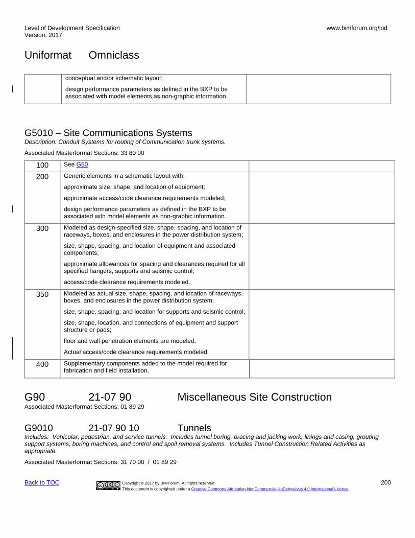
Level of Development Specification Version: 2017
www.bimforum.org/lod
Uniformat Omniclass
Back to TOC Copyright © 2017 by BIMForum. All rights reserved 200
This document is copyrighted under a Creative Commons Attribution-NonCommercial-NoDerivatives 4.0 International License.
conceptual and/or schematic layout;
design performance parameters as defined in the BXP to be associated with model elements as non-graphic information.
G5010 – Site Communications Systems Description: Conduit Systems for routing of Communication trunk systems.
Associated Masterformat Sections: 33 80 00
100 See G50
200 Generic elements in a schematic layout with:
approximate size, shape, and location of equipment;
approximate access/code clearance requirements modeled;
design performance parameters as defined in the BXP to be associated with model elements as non-graphic information.
300 Modeled as design-specified size, shape, spacing, and location of raceways, boxes, and enclosures in the power distribution system;
size, shape, spacing, and location of equipment and associated components;
approximate allowances for spacing and clearances required for all specified hangers, supports and seismic control;
access/code clearance requirements modeled.
350 Modeled as actual size, shape, spacing, and location of raceways, boxes, and enclosures in the power distribution system;
size, shape, spacing, and location for supports and seismic control;
size, shape, location, and connections of equipment and support structure or pads;
floor and wall penetration elements are modeled.
Actual access/code clearance requirements modeled.
400 Supplementary components added to the model required for fabrication and field installation.
G90 21-07 90 Miscellaneous Site Construction Associated Masterformat Sections: 01 89 29
G9010 21-07 90 10 Tunnels Includes: Vehicular, pedestrian, and service tunnels. Includes tunnel boring, bracing and jacking work, linings and casing, grouting support systems, boring machines, and control and spoil removal systems. Includes Tunnel Construction Related Activities as appropriate.
Associated Masterformat Sections: 31 70 00 / 01 89 29
Level of Development Specification Version: 2017
www.bimforum.org/lod
Uniformat Omniclass
Back to TOC Copyright © 2017 by BIMForum. All rights reserved 201
This document is copyrighted under a Creative Commons Attribution-NonCommercial-NoDerivatives 4.0 International License.
[See Fundamental LOD Definitions]

Level of Development Specification Version: 2017
www.bimforum.org/lod
Uniformat Omniclass
Back to TOC Copyright © 2017 by BIMForum. All rights reserved 202
This document is copyrighted under a Creative Commons Attribution-NonCommercial-NoDerivatives 4.0 International License.
N/A 23-13 STRUCTURAL AND EXTERIOR ENCLOSURE PRODUCTS
N/A 23-13-23 Mechanical Fasteners, Adhesives, and Sealants
N/A 23-13 23 11 Mechanical Fasteners – L-Bolt Includes: Cast-in anchors per American Concrete Institute 318 building code.
Associated Masterformat Sections: N/A
200 Refer to the model element of the main assembly being connected.
N/A
300 Refer to the model element of the main assembly being connected.
N/A
350 Element modeling to include:
• Anchor Length
• Embedment Length
• Projection Length
• Edge Distance Zone
• Spacing Zone
• Geometry, base size without threads
Required non-graphic information associated with model elements to include:
• Anchor materials defined
• Anchor type defined
• Base material type (steel, concrete, masonry, etc)
• Base material strength
• Base material condition (New, existing, cracked, uncracked, saturated, etc.)
• Finishes, i.e. primed, galvanized, etc.
LOD 350 L-Bolt Anchor

Level of Development Specification Version: 2017
www.bimforum.org/lod
Uniformat Omniclass
Back to TOC Copyright © 2017 by BIMForum. All rights reserved 203
This document is copyrighted under a Creative Commons Attribution-NonCommercial-NoDerivatives 4.0 International License.
400 Element modeling to include fabrication level information:
• Anchor Threads
• Anchor Washers
• Anchor Nuts Other non-graphic information may be included such as:
• Mark identification that correlates with bill of material (i.e., piece mark)
• Member finish (primer, galvanized, etc.)
• Fastener finish (i.e., black, zinc electroplated, hot-dipped galvanized)
LOD 400 L-Bolt Anchor
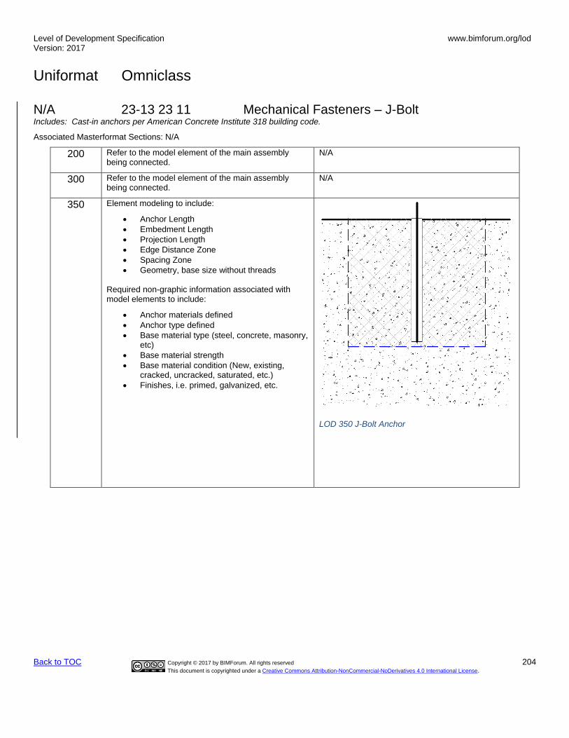
Level of Development Specification Version: 2017
www.bimforum.org/lod
Uniformat Omniclass
Back to TOC Copyright © 2017 by BIMForum. All rights reserved 204
This document is copyrighted under a Creative Commons Attribution-NonCommercial-NoDerivatives 4.0 International License.
N/A 23-13 23 11 Mechanical Fasteners – J-Bolt Includes: Cast-in anchors per American Concrete Institute 318 building code.
Associated Masterformat Sections: N/A
200 Refer to the model element of the main assembly being connected.
N/A
300 Refer to the model element of the main assembly being connected.
N/A
350 Element modeling to include:
• Anchor Length
• Embedment Length
• Projection Length
• Edge Distance Zone
• Spacing Zone
• Geometry, base size without threads
Required non-graphic information associated with model elements to include:
• Anchor materials defined
• Anchor type defined
• Base material type (steel, concrete, masonry, etc)
• Base material strength
• Base material condition (New, existing, cracked, uncracked, saturated, etc.)
• Finishes, i.e. primed, galvanized, etc.
LOD 350 J-Bolt Anchor
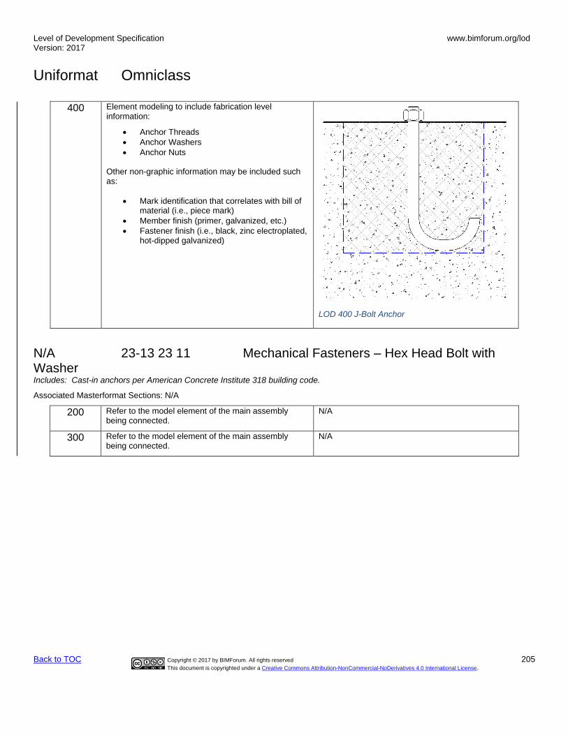
Level of Development Specification Version: 2017
www.bimforum.org/lod
Uniformat Omniclass
Back to TOC Copyright © 2017 by BIMForum. All rights reserved 205
This document is copyrighted under a Creative Commons Attribution-NonCommercial-NoDerivatives 4.0 International License.
400 Element modeling to include fabrication level information:
• Anchor Threads
• Anchor Washers
• Anchor Nuts Other non-graphic information may be included such as:
• Mark identification that correlates with bill of material (i.e., piece mark)
• Member finish (primer, galvanized, etc.)
• Fastener finish (i.e., black, zinc electroplated, hot-dipped galvanized)
LOD 400 J-Bolt Anchor
N/A 23-13 23 11 Mechanical Fasteners – Hex Head Bolt with Washer Includes: Cast-in anchors per American Concrete Institute 318 building code.
Associated Masterformat Sections: N/A
200 Refer to the model element of the main assembly being connected.
N/A
300 Refer to the model element of the main assembly being connected.
N/A

Level of Development Specification Version: 2017
www.bimforum.org/lod
Uniformat Omniclass
Back to TOC Copyright © 2017 by BIMForum. All rights reserved 206
This document is copyrighted under a Creative Commons Attribution-NonCommercial-NoDerivatives 4.0 International License.
350 Element modeling to include:
• Anchor Length
• Embedment Length
• Projection Length
• Edge Distance Zone
• Spacing Zone
• Geometry, base size without threads
Required non-graphic information associated with model elements to include:
• Anchor materials defined
• Anchor type defined
• Base material type (steel, concrete, masonry, etc)
• Base material strength
• Base material condition (New, existing, cracked, uncracked, saturated, etc.)
• Finishes, i.e. primed, galvanized, etc.
LOD 350 Hex Head Bolt with Washer
400 Element modeling to include fabrication level information:
• Anchor Threads
• Anchor Washers
• Anchor Nuts Other non-graphic information may be included such as:
• Mark identification that correlates with bill of material (i.e., piece mark)
• Member finish (primer, galvanized, etc.)
• Fastener finish (i.e., black, zinc electroplated, hot-dipped galvanized)
LOD 400 Hex Head Bolt with Washer

Level of Development Specification Version: 2017
www.bimforum.org/lod
Uniformat Omniclass
Back to TOC Copyright © 2017 by BIMForum. All rights reserved 207
This document is copyrighted under a Creative Commons Attribution-NonCommercial-NoDerivatives 4.0 International License.
N/A 23-13 23 11 Mechanical Fasteners – Welded Headed Stud Bolt Includes: Cast-in anchors per American Concrete Institute 318 building code.
Associated Masterformat Sections: N/A
200 Refer to the model element of the main assembly being connected.
N/A
300 Refer to the model element of the main assembly being connected.
N/A
350 Element modeling to include:
• Anchor Length
• Embedment Length
• Projection Length
• Edge Distance Zone
• Spacing Zone
• Geometry, base size without threads
Required non-graphic information associated with model elements to include:
• Anchor materials defined
• Anchor type defined
• Base material type (steel, concrete, masonry, etc)
• Base material strength
• Base material condition (New, existing, cracked, uncracked, saturated, etc.)
• Finishes, i.e. primed, galvanized, etc.
LOD 350 Welded Headed Stud Bolt
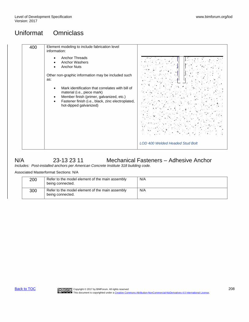
Level of Development Specification Version: 2017
www.bimforum.org/lod
Uniformat Omniclass
Back to TOC Copyright © 2017 by BIMForum. All rights reserved 208
This document is copyrighted under a Creative Commons Attribution-NonCommercial-NoDerivatives 4.0 International License.
400 Element modeling to include fabrication level information:
• Anchor Threads
• Anchor Washers
• Anchor Nuts Other non-graphic information may be included such as:
• Mark identification that correlates with bill of material (i.e., piece mark)
• Member finish (primer, galvanized, etc.)
• Fastener finish (i.e., black, zinc electroplated, hot-dipped galvanized)
LOD 400 Welded Headed Stud Bolt
N/A 23-13 23 11 Mechanical Fasteners – Adhesive Anchor Includes: Post-installed anchors per American Concrete Institute 318 building code.
Associated Masterformat Sections: N/A
200 Refer to the model element of the main assembly being connected.
N/A
300 Refer to the model element of the main assembly being connected.
N/A
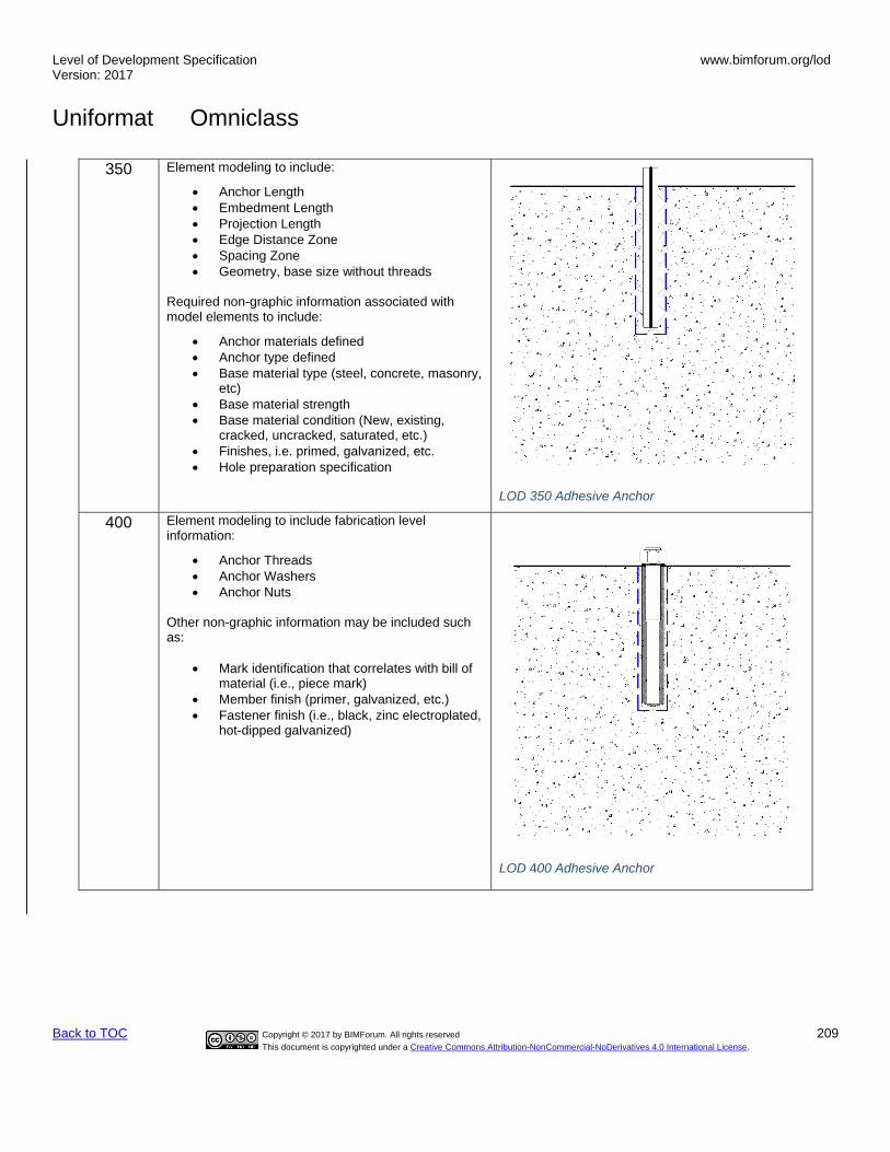
Level of Development Specification Version: 2017
www.bimforum.org/lod
Uniformat Omniclass
Back to TOC Copyright © 2017 by BIMForum. All rights reserved 209
This document is copyrighted under a Creative Commons Attribution-NonCommercial-NoDerivatives 4.0 International License.
350 Element modeling to include:
• Anchor Length
• Embedment Length
• Projection Length
• Edge Distance Zone
• Spacing Zone
• Geometry, base size without threads
Required non-graphic information associated with model elements to include:
• Anchor materials defined
• Anchor type defined
• Base material type (steel, concrete, masonry, etc)
• Base material strength
• Base material condition (New, existing, cracked, uncracked, saturated, etc.)
• Finishes, i.e. primed, galvanized, etc.
• Hole preparation specification
LOD 350 Adhesive Anchor
400 Element modeling to include fabrication level information:
• Anchor Threads
• Anchor Washers
• Anchor Nuts Other non-graphic information may be included such as:
• Mark identification that correlates with bill of material (i.e., piece mark)
• Member finish (primer, galvanized, etc.)
• Fastener finish (i.e., black, zinc electroplated, hot-dipped galvanized)
LOD 400 Adhesive Anchor

Level of Development Specification Version: 2017
www.bimforum.org/lod
Uniformat Omniclass
Back to TOC Copyright © 2017 by BIMForum. All rights reserved 210
This document is copyrighted under a Creative Commons Attribution-NonCommercial-NoDerivatives 4.0 International License.
N/A 23-13 23 11 Mechanical Fasteners – Undercut Anchor Includes: Post-installed anchors per American Concrete Institute 318 building code.
Associated Masterformat Sections: N/A
200 Refer to the model element of the main assembly being connected.
N/A
300 Refer to the model element of the main assembly being connected.
N/A
350 Element modeling to include:
• Anchor Length
• Embedment Length
• Projection Length
• Edge Distance Zone
• Spacing Zone
• Geometry, base size without threads
Required non-graphic information associated with model elements to include:
• Anchor materials defined
• Anchor type defined
• Base material type (steel, concrete, masonry, etc)
• Base material strength
• Base material condition (New, existing, cracked, uncracked, saturated, etc.)
• Finishes, i.e. primed, galvanized, etc.
• Hole preparation specification
LOD 350 Undercut Anchor

Level of Development Specification Version: 2017
www.bimforum.org/lod
Uniformat Omniclass
Back to TOC Copyright © 2017 by BIMForum. All rights reserved 211
This document is copyrighted under a Creative Commons Attribution-NonCommercial-NoDerivatives 4.0 International License.
400 Element modeling to include fabrication level information:
• Anchor Threads
• Anchor Washers
• Anchor Nuts Other non-graphic information may be included such as:
• Mark identification that correlates with bill of material (i.e., piece mark)
• Member finish (primer, galvanized, etc.)
• Fastener finish (i.e., black, zinc electroplated, hot-dipped galvanized)
LOD 400 Undercut Anchor

Level of Development Specification Version: 2017
www.bimforum.org/lod
Uniformat Omniclass
Back to TOC Copyright © 2017 by BIMForum. All rights reserved 212
This document is copyrighted under a Creative Commons Attribution-NonCommercial-NoDerivatives 4.0 International License.
N/A 23-13 23 11 Mechanical Fasteners – Torque-controlled Expansion Anchor (Sleeve Type) Includes: Post-installed anchors per American Concrete Institute 318 building code.
Associated Masterformat Sections: N/A
200 Refer to the model element of the main assembly being connected.
N/A
300 Refer to the model element of the main assembly being connected.
N/A
350 Element modeling to include:
• Anchor Length
• Embedment Length
• Projection Length
• Edge Distance Zone
• Spacing Zone
• Geometry, base size without threads
Required non-graphic information associated with model elements to include:
• Anchor materials defined
• Anchor type defined
• Base material type (steel, concrete, masonry, etc)
• Base material strength
• Base material condition (New, existing, cracked, uncracked, saturated, etc.)
• Finishes, i.e. primed, galvanized, etc.
• Hole preparation specification
LOD 350 Torque-Controlled Expansion Anchor (Sleeve Type)

Level of Development Specification Version: 2017
www.bimforum.org/lod
Uniformat Omniclass
Back to TOC Copyright © 2017 by BIMForum. All rights reserved 213
This document is copyrighted under a Creative Commons Attribution-NonCommercial-NoDerivatives 4.0 International License.
400 Element modeling to include fabrication level information:
• Anchor Threads
• Anchor Washers
• Anchor Nuts Other non-graphic information may be included such as:
• Mark identification that correlates with bill of material (i.e., piece mark)
• Member finish (primer, galvanized, etc.)
• Fastener finish (i.e., black, zinc electroplated, hot-dipped galvanized)
LOD 400 Torque-Controlled Expansion Anchor (Sleeve Type)

Level of Development Specification Version: 2017
www.bimforum.org/lod
Uniformat Omniclass
Back to TOC Copyright © 2017 by BIMForum. All rights reserved 214
This document is copyrighted under a Creative Commons Attribution-NonCommercial-NoDerivatives 4.0 International License.
N/A 23-13 23 11 Mechanical Fasteners – Torque-controlled Expansion Anchor (Stud Type) Includes: Post-installed anchors per American Concrete Institute 318 building code.
Associated Masterformat Sections: N/A
200 Refer to the model element of the main assembly being connected.
N/A
300 Refer to the model element of the main assembly being connected.
N/A
350 Element modeling to include:
• Anchor Length
• Embedment Length
• Projection Length
• Edge Distance Zone
• Spacing Zone
• Geometry, base size without threads
Required non-graphic information associated with model elements to include:
• Anchor materials defined
• Anchor type defined
• Base material type (steel, concrete, masonry, etc)
• Base material strength
• Base material condition (New, existing, cracked, uncracked, saturated, etc.)
• Finishes, i.e. primed, galvanized, etc.
• Hole preparation specification
LOD 350 Torque-Controlled Expansion Anchor (Stud Type)

Level of Development Specification Version: 2017
www.bimforum.org/lod
Uniformat Omniclass
Back to TOC Copyright © 2017 by BIMForum. All rights reserved 215
This document is copyrighted under a Creative Commons Attribution-NonCommercial-NoDerivatives 4.0 International License.
400 Element modeling to include fabrication level information:
• Anchor Threads
• Anchor Washers
• Anchor Nuts Other non-graphic information may be included such as:
• Mark identification that correlates with bill of material (i.e., piece mark)
• Member finish (primer, galvanized, etc.)
• Fastener finish (i.e., black, zinc electroplated, hot-dipped galvanized)
LOD 400 Torque-Controlled Expansion Anchor (Stud Type)

Level of Development Specification Version: 2017
www.bimforum.org/lod
Uniformat Omniclass
Back to TOC Copyright © 2017 by BIMForum. All rights reserved 216
This document is copyrighted under a Creative Commons Attribution-NonCommercial-NoDerivatives 4.0 International License.
N/A 23-13 23 11 Mechanical Fasteners – Drop-in Type Displacement-Controlled Expansion Anchor Includes: Post-installed anchors per American Concrete Institute 318 building code.
Associated Masterformat Sections: N/A
200 Refer to the model element of the main assembly being connected.
N/A
300 Refer to the model element of the main assembly being connected.
N/A
350 Element modeling to include:
• Anchor Length
• Embedment Length
• Projection Length
• Edge Distance Zone
• Spacing Zone
• Geometry, base size without threads
Required non-graphic information associated with model elements to include:
• Anchor materials defined
• Anchor type defined
• Base material type (steel, concrete, masonry, etc)
• Base material strength
• Base material condition (New, existing, cracked, uncracked, saturated, etc.)
• Finishes, i.e. primed, galvanized, etc.
• Hole preparation specification
LOD 350 Drop-In Type Displacement-Controlled Expansion Anchor

Level of Development Specification Version: 2017
www.bimforum.org/lod
Uniformat Omniclass
Back to TOC Copyright © 2017 by BIMForum. All rights reserved 217
This document is copyrighted under a Creative Commons Attribution-NonCommercial-NoDerivatives 4.0 International License.
400 Element modeling to include fabrication level information:
• Anchor Threads
• Anchor Washers
• Anchor Nuts Other non-graphic information may be included such as:
• Mark identification that correlates with bill of material (i.e., piece mark)
• Member finish (primer, galvanized, etc.)
• Fastener finish (i.e., black, zinc electroplated, hot-dipped galvanized)
LOD 400 Drop-In Type Displacement-Controlled Expansion Anchor
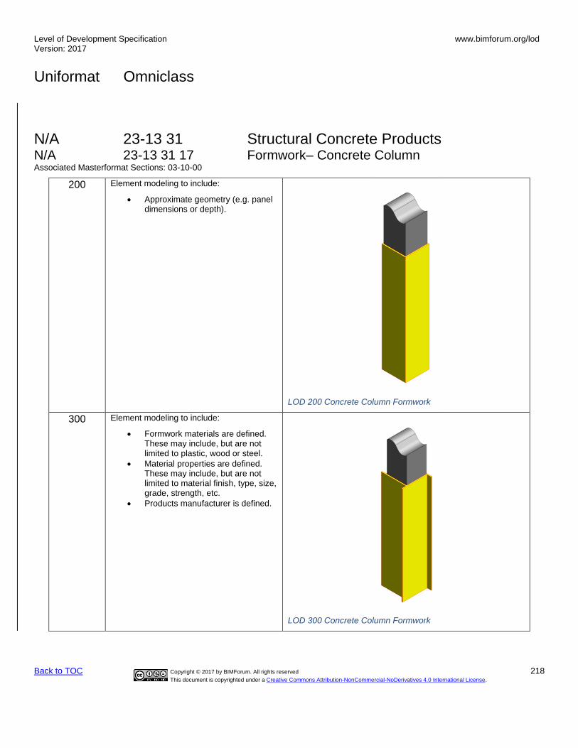
Level of Development Specification Version: 2017
www.bimforum.org/lod
Uniformat Omniclass
Back to TOC Copyright © 2017 by BIMForum. All rights reserved 218
This document is copyrighted under a Creative Commons Attribution-NonCommercial-NoDerivatives 4.0 International License.
N/A 23-13 31 Structural Concrete Products N/A 23-13 31 17 Formwork– Concrete Column Associated Masterformat Sections: 03-10-00
200 Element modeling to include:
• Approximate geometry (e.g. panel dimensions or depth).
LOD 200 Concrete Column Formwork
300 Element modeling to include:
• Formwork materials are defined. These may include, but are not limited to plastic, wood or steel.
• Material properties are defined. These may include, but are not limited to material finish, type, size, grade, strength, etc.
• Products manufacturer is defined.
LOD 300 Concrete Column Formwork

Level of Development Specification Version: 2017
www.bimforum.org/lod
Uniformat Omniclass
Back to TOC Copyright © 2017 by BIMForum. All rights reserved 219
This document is copyrighted under a Creative Commons Attribution-NonCommercial-NoDerivatives 4.0 International License.
350 Element modeling to include:
• Insulating faces are defined.
• Insulating details are defined. These include, but are not limited, too, the type of insulation specified, the temperature change the insulation will cause and the thickness of the insulation within the formwork.
• Hardware and fastener specification defined (may include Nails, Wood Screws, Bolts, Lag Screws, Ties, Anchors, Hangers, etc.)
• Shoring connections are defined.
• Scaffolding connections are defined
• Liner details are defined.
LOD 350 Concrete Column Formwork
400 Element modeling to include:
• All connections. fasteners, and forms detailed and modeled.
• Nails, Screws, Anchors, etc.
LOD 400 Concrete Column Formwork
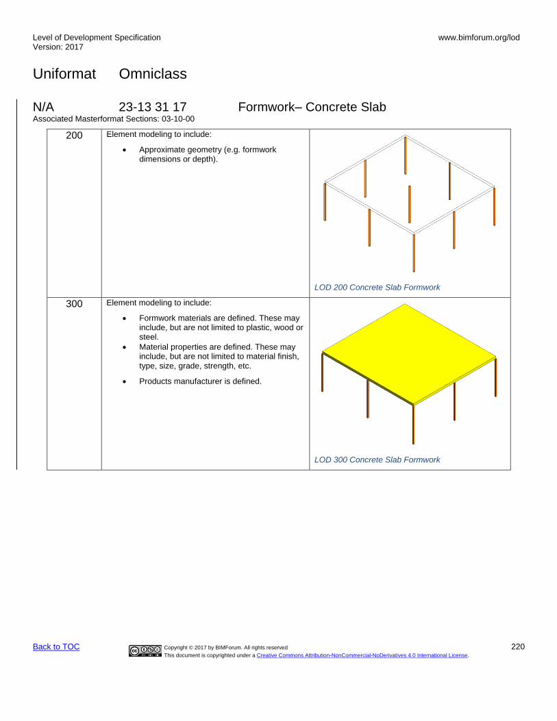
Level of Development Specification Version: 2017
www.bimforum.org/lod
Uniformat Omniclass
Back to TOC Copyright © 2017 by BIMForum. All rights reserved 220
This document is copyrighted under a Creative Commons Attribution-NonCommercial-NoDerivatives 4.0 International License.
N/A 23-13 31 17 Formwork– Concrete Slab Associated Masterformat Sections: 03-10-00
200 Element modeling to include:
• Approximate geometry (e.g. formwork dimensions or depth).
LOD 200 Concrete Slab Formwork
300 Element modeling to include:
• Formwork materials are defined. These may include, but are not limited to plastic, wood or steel.
• Material properties are defined. These may include, but are not limited to material finish, type, size, grade, strength, etc.
• Products manufacturer is defined.
LOD 300 Concrete Slab Formwork

Level of Development Specification Version: 2017
www.bimforum.org/lod
Uniformat Omniclass
Back to TOC Copyright © 2017 by BIMForum. All rights reserved 221
This document is copyrighted under a Creative Commons Attribution-NonCommercial-NoDerivatives 4.0 International License.
350 Element modeling to include:
• Insulating faces are defined.
• Insulating details are defined. These include, but are not limited, too, the type of insulation specified, the temperature change the insulation will cause and the thickness of the insulation within the formwork.
• Hardware and fastener specification defined (may include Nails, Wood Screws, Bolts, Lag Screws, Ties, Anchors, Hangers, etc.)
• Shoring connections are defined.
• Scaffolding connections are defined
• Liner details are defined.
LOD 350 Concrete Slab Formwork
400 Element modeling to include:
• All supports and formwork detailed and modeled.
• Wood supports, metal supports, plates, etc.
LOD 400 Concrete Slab Formwork

Level of Development Specification Version: 2017
www.bimforum.org/lod
Uniformat Omniclass
Back to TOC Copyright © 2017 by BIMForum. All rights reserved 222
This document is copyrighted under a Creative Commons Attribution-NonCommercial-NoDerivatives 4.0 International License.
CIVIL
Highway Bridges Precast Structural I Girder (Concrete)
100
200 Element modeling to include:
• Type of structural concrete system
• Approximate geometry (e.g. depth) of structural elements
LOD 200 Highway Bridges Precast Structural I Girder (Concrete)
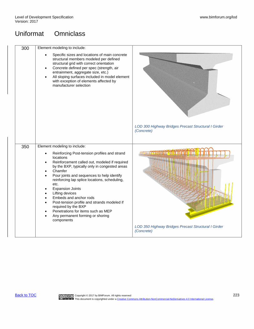
Level of Development Specification Version: 2017
www.bimforum.org/lod
Uniformat Omniclass
Back to TOC Copyright © 2017 by BIMForum. All rights reserved 223
This document is copyrighted under a Creative Commons Attribution-NonCommercial-NoDerivatives 4.0 International License.
300 Element modeling to include:
• Specific sizes and locations of main concrete structural members modeled per defined structural grid with correct orientation
• Concrete defined per spec (strength, air entrainment, aggregate size, etc.)
• All sloping surfaces included in model element with exception of elements affected by manufacturer selection
350 Element modeling to include:
• Reinforcing Post-tension profiles and strand locations
• Reinforcement called out, modeled if required by the BXP, typically only in congested areas
• Chamfer
• Pour joints and sequences to help identify reinforcing lap splice locations, scheduling, etc.
• Expansion Joints
• Lifting devices
• Embeds and anchor rods
• Post-tension profile and strands modeled if required by the BXP
• Penetrations for items such as MEP
• Any permanent forming or shoring components
LOD 350 Highway Bridges Precast Structural I Girder (Concrete)
LOD 300 Highway Bridges Precast Structural I Girder (Concrete)

Level of Development Specification Version: 2017
www.bimforum.org/lod
Uniformat Omniclass
Back to TOC Copyright © 2017 by BIMForum. All rights reserved 224
This document is copyrighted under a Creative Commons Attribution-NonCommercial-NoDerivatives 4.0 International License.
400 Element modeling to include:
• All reinforcement including post tension elements detailed and modeled
LOD 400 Highway Bridges Precast Structural I Girder (Concrete)

Level of Development Specification Version: 2017
www.bimforum.org/lod
Uniformat Omniclass
Back to TOC Copyright © 2017 by BIMForum. All rights reserved 225
This document is copyrighted under a Creative Commons Attribution-NonCommercial-NoDerivatives 4.0 International License.
Highway Bridge Girder Steel 200 Generic mass of Girder
LOD 200 Highway Bridge Girder Steel
300 Element modeling to include 3) Girder Depth 4) Web Plate Length
• Flange Plate Width
LOD 300 Highway Bridge Girder Steel

Level of Development Specification Version: 2017
www.bimforum.org/lod
Uniformat Omniclass
Back to TOC Copyright © 2017 by BIMForum. All rights reserved 226
This document is copyrighted under a Creative Commons Attribution-NonCommercial-NoDerivatives 4.0 International License.
350 Element modeling to include:
• Stiffeners
• Exact sloping of members
• Splits between Plate Girders
LOD 350 Highway Bridge Girder Steel
400 Element modeling to include fabrication level information:
• Welds
• Coping of members
• Washers, nuts, etc.
• Grating, holes in grating
• All assembly elements
LOD 400 Highway Bridge Girder Steel
Railroad Bridges Precast Structural I Girder (Concrete)
100
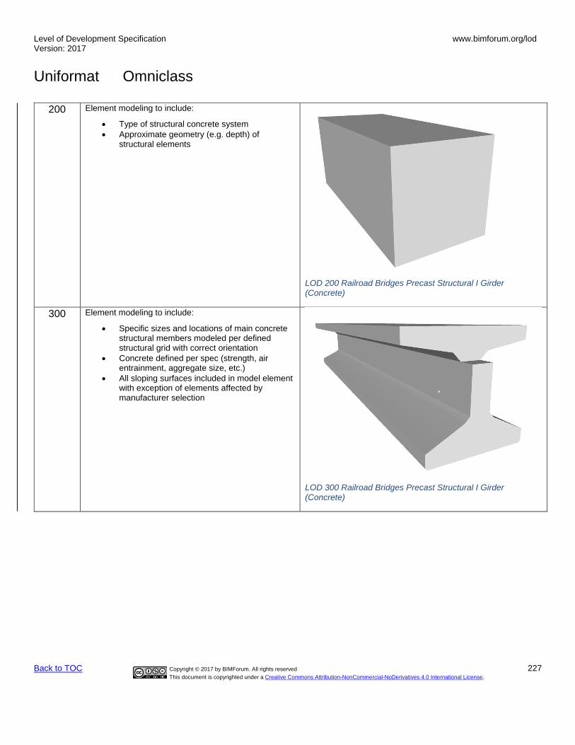
Level of Development Specification Version: 2017
www.bimforum.org/lod
Uniformat Omniclass
Back to TOC Copyright © 2017 by BIMForum. All rights reserved 227
This document is copyrighted under a Creative Commons Attribution-NonCommercial-NoDerivatives 4.0 International License.
200 Element modeling to include:
• Type of structural concrete system
• Approximate geometry (e.g. depth) of structural elements
LOD 200 Railroad Bridges Precast Structural I Girder (Concrete)
300 Element modeling to include:
• Specific sizes and locations of main concrete structural members modeled per defined structural grid with correct orientation
• Concrete defined per spec (strength, air entrainment, aggregate size, etc.)
• All sloping surfaces included in model element with exception of elements affected by manufacturer selection
LOD 300 Railroad Bridges Precast Structural I Girder (Concrete)

Level of Development Specification Version: 2017
www.bimforum.org/lod
Uniformat Omniclass
Back to TOC Copyright © 2017 by BIMForum. All rights reserved 228
This document is copyrighted under a Creative Commons Attribution-NonCommercial-NoDerivatives 4.0 International License.
350 Element modeling to include:
• Reinforcing Post-tension profiles and strand locations
• Reinforcement called out, modeled if required by the BXP, typically only in congested areas
• Pour joints and sequences to help identify reinforcing lap splice locations, scheduling, etc.
• Chamfer
• Expansion Joints
• Lifting devices
• Embeds and anchor rods
• Post-tension profile and strands modeled if required by the BXP
• Penetrations for items such as MEP
• Any permanent forming or shoring components
LOD 350 Railroad Bridges Precast Structural I Girder (Concrete)
400 Element modeling to include:
• All reinforcement including post tension elements detailed and modeled
• Finishes
LOD 400 Railroad Bridges Precast Structural I Girder (Concrete)
Railroad Bridge Girder Steel

Level of Development Specification Version: 2017
www.bimforum.org/lod
Uniformat Omniclass
Back to TOC Copyright © 2017 by BIMForum. All rights reserved 229
This document is copyrighted under a Creative Commons Attribution-NonCommercial-NoDerivatives 4.0 International License.
200 Generic mass of Girder
LOD 200 Railroad Bridge Girder Steel
300 Element modeling to include:
• Girder Depth
• Web Plate Length
• Flange Plate Width
LOD 300 Railroad Bridge Girder Steel
350 Element modeling to include:
• Stiffeners
• Exact sloping of members
• Splits between Plate Girders
LOD 350 Railroad Bridge Girder Steel
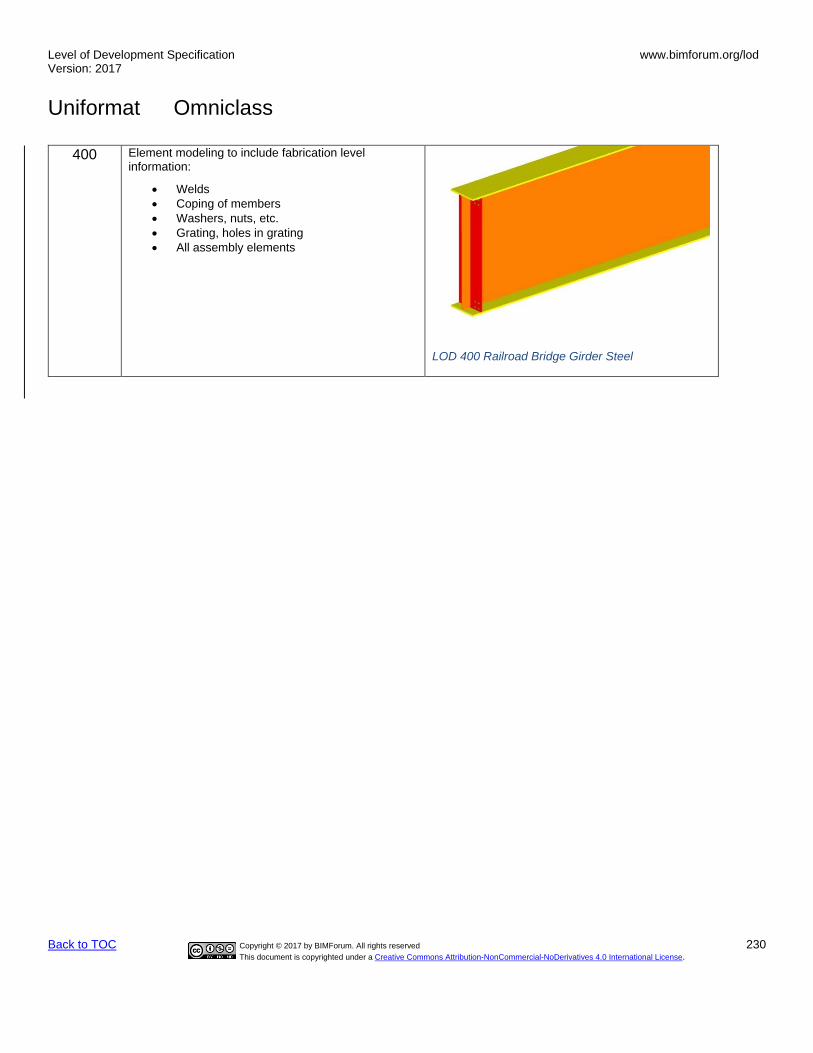
Level of Development Specification Version: 2017
www.bimforum.org/lod
Uniformat Omniclass
Back to TOC Copyright © 2017 by BIMForum. All rights reserved 230
This document is copyrighted under a Creative Commons Attribution-NonCommercial-NoDerivatives 4.0 International License.
400 Element modeling to include fabrication level information:
• Welds
• Coping of members
• Washers, nuts, etc.
• Grating, holes in grating
• All assembly elements
LOD 400 Railroad Bridge Girder Steel