LoD for Procedural Urban Models
4
Recent Advances on LoD for Procedural Urban Models Gonzalo Besuievsky and Gustavo Patow Geometry and Graphics Group, Universitat de Giorna, Spain Abstract Procedural Urban Models have been proven to be an efficient tech- nique for generating detailed city models, and an increasing range of applications, such as urban planning and simulation, aside from visualization, are using these technique for model generation. How- ever, the amount of geometry generated could be huge and properly controlling it is still a challenge. This paper reviews our recent works for generating LoD in Proce- dural Urban Models, with the aim to discuss new trends that should be tackled to explore the use of this technique in urban applica- tions. 1 Introduction Urban models are complex systems that need to be managed at dif- ferent correlated scales such as building-scale, district-scale or city- scale, depending on the application requirements. These large-data sets are usually built from different sources like cadastral data, dig- ital images or CAD models. The treatment of the data concerning new techniques for generating different scale-model is a current re- search topic in domains like modeling simulation [Robinson 2011; Beckers 2012] and visualization [He et al. 2012]. Concerning model generation, procedural modeling appears as an efficient solution to the labour-intensive modeling task of content creation. Although with this technique large models with details can be generated, in many situations ranging from a single-user walkthroughs up to urban simulations, there is no need of the full geometry. The generation of level of detail (LoD) is essential for any kind of city models. The concept of representing models at dif- ferent LoDs is well-known from Computer Graphics and Visualiza- tion domains. However, for procedural city models, the classic so- lution of processing an already generated model by using reduction techniques to simplify the model from quality parameters [Luebke et al. 2002] is not the best way to proceed. The full geometry gener- ation that could contain several millions of polygons must be avoid. Also, proposals should take into account not only the complexity in terms of number of polygons, but also their semantics or phys- ical meaning, depending on the requirements. Thus, for procedu- ral modeling, the simplification should be generated automatically within the procedural creation. In this paper we report our recent advances for improving procedu- ral techniques through the development of more flexible and auto- matic control tools for model generation. 2 Level-of-Details Analysis Specific works on level of detail for building models can be found in different contexts. For cartographic generalization, Anders [2005] proposed an approach for the aggregation of linearly arranged building groups. Other works focus on building simplification by collapsing faces from known constructive structures as walls and roofs. Chang et al. [Chang et al. 2008] presented a large scale sim- plification approach based on ”urban legibility” intended for bet- ter preserving understandability for complex urban spaces at all levels of simplification. Other LoD proposals like the CityGML schema [Kolbe 2009] differentiates between five consecutive LoD- levels, which become more detailed with increasing LoD regarding both geometry and thematic functionality differentiation. Although the initiatives for LoD definitions, the main question for the conception and generation is given from the criteria that drives the geometry levels. This criteria is always attached to the particular requirements. For instance, standard LoD in Computer Graphics is driven by the complexity of the geometry, whereas for CityGML the semantic is also taken into account to define the levels. 3 LoD in Procedural Modeling The seminal works by Wonka et al. [Wonka et al. 2003] and M¨ uller et al. [M¨ uller et al. 2006] introduced Grammar-based pro- cedural modeling for buildings. The main concept of this tech- nique is a shape grammar, which is based on a ruleset: starting from an initial axiom primitive (e.g. a building outline), rules are iteratively applied, replacing shapes with other shapes. A rule has a labeled shape on the left hand side, called predeces- sor, and one or multiple shapes (also called primitives) and com- mands on the right hand side, called successor: predecessor → CommandA, CommandB : labelB; labelB → CommandC : labelC. The resulting geometry is formed by shapes that can be optionally assigned new labels to be further processed. The main commands, the macros that create new shapes in the classic ap- proach, are: Subdivision, that performs a subdivision of the current shape into multiple shapes; Repeat, that performs a repeated sub- division of one shape multiple times; Component split, that creates new components shapes (faces or edges) from initial volumes; and Insert command that replaces a pre-made asset on a current prede- cessor. Traditionally, grammars create a hierarchy of shapes by processing each rule’s predecessor shape, replacing it by its products. This process is executed until only terminal shapes are left. The whole production process can be seen as a Directed Acyclic Graph (DAG), where each node represents an operation applied to its incoming geometry stream and the leaf nodes are the geometry assets (see Figure 1) [Patow 2012]. One of the strategies followed for LoD generation in order to avoid simplification over the full model is to transform the graph according to some specific criteria. In this section we review the main contributions. 3.1 LoD by Configurable Rules One of the basic ways to achieve levels of detail for procedu- ral modeling is by directly configuring rules. An initial proposal intended for city generation was presented by Parish and M¨ uller [2001] based on the L-system recursive nature. Automatic LoD- generation can be obtained by starting from the building envelope as axiom, and where the output of each iteration represents a refin- ing step in the building generation. This kind of approach can be complemented by setting manually predefined LoD geometry for different levels. Industrial solutions, like CityEngine [Esri 2012], provide this kind of solution (see Fig. 2). Within this strategy, the final model is completed by manually introducing pre-made assets at different levels resolutions. The disadvantage here is that the mechanism requires manual writing rules for each case and also
Transcript of LoD for Procedural Urban Models
Recent Advances on LoD for Procedural Urban Models
Gonzalo Besuievsky and Gustavo PatowGeometry and Graphics Group,
Universitat de Giorna, Spain
Abstract
Procedural Urban Models have been proven to be an efficient tech-nique for generating detailed city models, and an increasing rangeof applications, such as urban planning and simulation, aside fromvisualization, are using these technique for model generation. How-ever, the amount of geometry generated could be huge and properlycontrolling it is still a challenge.
This paper reviews our recent works for generating LoD in Proce-dural Urban Models, with the aim to discuss new trends that shouldbe tackled to explore the use of this technique in urban applica-tions.
1 Introduction
Urban models are complex systems that need to be managed at dif-ferent correlated scales such as building-scale, district-scale or city-scale, depending on the application requirements. These large-datasets are usually built from different sources like cadastral data, dig-ital images or CAD models. The treatment of the data concerningnew techniques for generating different scale-model is a current re-search topic in domains like modeling simulation [Robinson 2011;Beckers 2012] and visualization [He et al. 2012].
Concerning model generation, procedural modeling appears as anefficient solution to the labour-intensive modeling task of contentcreation. Although with this technique large models with detailscan be generated, in many situations ranging from a single-userwalkthroughs up to urban simulations, there is no need of the fullgeometry. The generation of level of detail (LoD) is essential forany kind of city models. The concept of representing models at dif-ferent LoDs is well-known from Computer Graphics and Visualiza-tion domains. However, for procedural city models, the classic so-lution of processing an already generated model by using reductiontechniques to simplify the model from quality parameters [Luebkeet al. 2002] is not the best way to proceed. The full geometry gener-ation that could contain several millions of polygons must be avoid.Also, proposals should take into account not only the complexityin terms of number of polygons, but also their semantics or phys-ical meaning, depending on the requirements. Thus, for procedu-ral modeling, the simplification should be generated automaticallywithin the procedural creation.
In this paper we report our recent advances for improving procedu-ral techniques through the development of more flexible and auto-matic control tools for model generation.
2 Level-of-Details Analysis
Specific works on level of detail for building models can be found indifferent contexts. For cartographic generalization, Anders [2005]proposed an approach for the aggregation of linearly arrangedbuilding groups. Other works focus on building simplification bycollapsing faces from known constructive structures as walls androofs. Chang et al. [Chang et al. 2008] presented a large scale sim-plification approach based on ”urban legibility” intended for bet-ter preserving understandability for complex urban spaces at alllevels of simplification. Other LoD proposals like the CityGML
schema [Kolbe 2009] differentiates between five consecutive LoD-levels, which become more detailed with increasing LoD regardingboth geometry and thematic functionality differentiation.
Although the initiatives for LoD definitions, the main question forthe conception and generation is given from the criteria that drivesthe geometry levels. This criteria is always attached to the particularrequirements. For instance, standard LoD in Computer Graphics isdriven by the complexity of the geometry, whereas for CityGMLthe semantic is also taken into account to define the levels.
3 LoD in Procedural Modeling
The seminal works by Wonka et al. [Wonka et al. 2003] andMuller et al. [Muller et al. 2006] introduced Grammar-based pro-cedural modeling for buildings. The main concept of this tech-nique is a shape grammar, which is based on a ruleset: startingfrom an initial axiom primitive (e.g. a building outline), rulesare iteratively applied, replacing shapes with other shapes. Arule has a labeled shape on the left hand side, called predeces-sor, and one or multiple shapes (also called primitives) and com-mands on the right hand side, called successor: predecessor →CommandA,CommandB : labelB; labelB → CommandC :labelC. The resulting geometry is formed by shapes that can beoptionally assigned new labels to be further processed. The maincommands, the macros that create new shapes in the classic ap-proach, are: Subdivision, that performs a subdivision of the currentshape into multiple shapes; Repeat, that performs a repeated sub-division of one shape multiple times; Component split, that createsnew components shapes (faces or edges) from initial volumes; andInsert command that replaces a pre-made asset on a current prede-cessor.
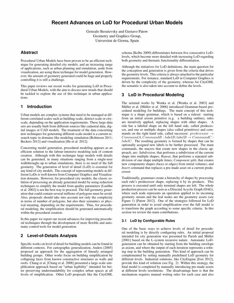
Traditionally, grammars create a hierarchy of shapes by processingeach rule’s predecessor shape, replacing it by its products. Thisprocess is executed until only terminal shapes are left. The wholeproduction process can be seen as a Directed Acyclic Graph (DAG),where each node represents an operation applied to its incominggeometry stream and the leaf nodes are the geometry assets (seeFigure 1) [Patow 2012]. One of the strategies followed for LoDgeneration in order to avoid simplification over the full model isto transform the graph according to some specific criteria. In thissection we review the main contributions.
3.1 LoD by Configurable Rules
One of the basic ways to achieve levels of detail for procedu-ral modeling is by directly configuring rules. An initial proposalintended for city generation was presented by Parish and Muller[2001] based on the L-system recursive nature. Automatic LoD-generation can be obtained by starting from the building envelopeas axiom, and where the output of each iteration represents a refin-ing step in the building generation. This kind of approach can becomplemented by setting manually predefined LoD geometry fordifferent levels. Industrial solutions, like CityEngine [Esri 2012],provide this kind of solution (see Fig. 2). Within this strategy, thefinal model is completed by manually introducing pre-made assetsat different levels resolutions. The disadvantage here is that themechanism requires manual writing rules for each case and also
LotCreateBase : mass
LotCreateBase : mass
massComp: facade, sides, roof
facadeSubdiv: bottom, middle, top
roofRoof
bottomSubdiv: floor, door
middleRepeat: floor
floorRepeat: window
doorInsert(door)
windowInsert(window)
windowInsert(frame)
Figure 1: A graph-based set of rules (top) is used to obtain a build-ing model (bottom).
that the geometry is drastically reduced without a smooth transitionbetween the different discrete levels.
Figure 2: LoD produced by manually configuring rules withCityEngine.
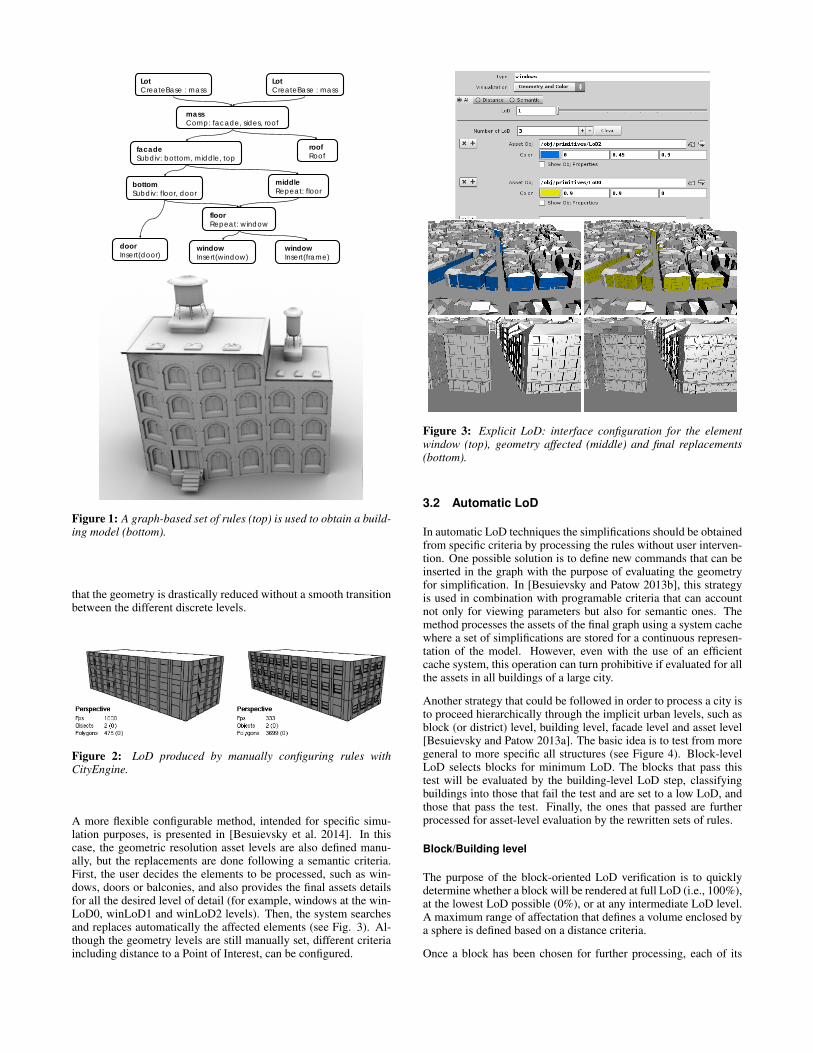
A more flexible configurable method, intended for specific simu-lation purposes, is presented in [Besuievsky et al. 2014]. In thiscase, the geometric resolution asset levels are also defined manu-ally, but the replacements are done following a semantic criteria.First, the user decides the elements to be processed, such as win-dows, doors or balconies, and also provides the final assets detailsfor all the desired level of detail (for example, windows at the win-LoD0, winLoD1 and winLoD2 levels). Then, the system searchesand replaces automatically the affected elements (see Fig. 3). Al-though the geometry levels are still manually set, different criteriaincluding distance to a Point of Interest, can be configured.
Figure 3: Explicit LoD: interface configuration for the elementwindow (top), geometry affected (middle) and final replacements(bottom).
3.2 Automatic LoD
In automatic LoD techniques the simplifications should be obtainedfrom specific criteria by processing the rules without user interven-tion. One possible solution is to define new commands that can beinserted in the graph with the purpose of evaluating the geometryfor simplification. In [Besuievsky and Patow 2013b], this strategyis used in combination with programable criteria that can accountnot only for viewing parameters but also for semantic ones. Themethod processes the assets of the final graph using a system cachewhere a set of simplifications are stored for a continuous represen-tation of the model. However, even with the use of an efficientcache system, this operation can turn prohibitive if evaluated for allthe assets in all buildings of a large city.
Another strategy that could be followed in order to process a city isto proceed hierarchically through the implicit urban levels, such asblock (or district) level, building level, facade level and asset level[Besuievsky and Patow 2013a]. The basic idea is to test from moregeneral to more specific all structures (see Figure 4). Block-levelLoD selects blocks for minimum LoD. The blocks that pass thistest will be evaluated by the building-level LoD step, classifyingbuildings into those that fail the test and are set to a low LoD, andthose that pass the test. Finally, the ones that passed are furtherprocessed for asset-level evaluation by the rewritten sets of rules.
Block/Building level
The purpose of the block-oriented LoD verification is to quicklydetermine whether a block will be rendered at full LoD (i.e., 100%),at the lowest LoD possible (0%), or at any intermediate LoD level.A maximum range of affectation that defines a volume enclosed bya sphere is defined based on a distance criteria.
Once a block has been chosen for further processing, each of its
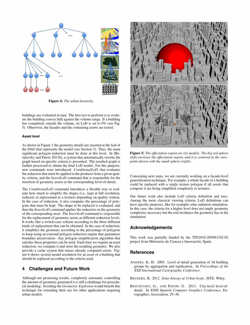
Figure 4: The urban herarchy.
buildings are evaluated in turn. The first test to perform is to evalu-ate the building convex hull against the volume range. If a buildinglies completely outside the volume, its LoD is set to 0% (see Fig.5). Otherwise, the facades and the containing assets are tested.
Asset level
As shown in Figure 1 the geometry details are inserted at the leaf ofthe DAG that represents the model (see Section 3). Thus, the mainsignificant polygon reduction must be done at this level. In [Be-suievsky and Patow 2013b], a system that automatically rewrite thegraph based on specific criteria is presented. The resulted graph isfurther processed to obtain the final LoD model. For this purpose,new commands were introduced: ConditionalLoD, that evaluatesthe reduction that must be applied to the products from a given qual-ity criteria, and the InsertLoD command that is responsible for theinsertion of geometry assets at the corresponding level-of-detail.
The ConditionalLoD command introduces a flexible way to eval-uate how much to simplify the shapes (i.e., kept at full resolution,reduced, or represented as a texture) depending on quality criteria.In the case of reduction, it also computes the percentage of poly-gons that must be kept. The shape to be replaced is evaluated, andthen the InsertLoD command applies the reduction on the geometryof the corresponding asset. The InsertLoD command is responsiblefor the replacement of geometry assets at different reduction levels.It works like a switch-case scheme according to the three differentkinds of replacement that can be obtained. In the case of reduction,it simplifies the geometry according to the percentage of polygonsto keep using an external polygon reduction engine that guaranteesboundary preservation. Any polygon simplification algorithm thatsatisfies these properties can be used. Each time we require an assetreduction, we compute it and store the resulting geometry. We alsoprovide a cache system that reuses already computed assets. Fig-ure 6 shows several model resolution for an asset of a building thatshould be replaced according to the criteria used.
4 Challenges and Future Work
Although our promising results, completely automatic controllingthe amount of geometry generated it is still a challenge for procedu-ral modeling. Avoiding the Geometric Explosion would benefit thistechnique for extending their use for other applications requiringurban models.
Figure 5: The affectation region on city models. The big red sphere(left) encloses the affectation region, and it is centered at the view-point shown with the small sphere (right).
Concerning next steps, we are currently working on a facade-levelgeneralization technique. For example, a whole facade of a buildingcould be replaced with a single texture polygon if all assets thatcompose it are being simplified completely to textures.
Our future work also include LoD criteria definition and uses.Among the more classical viewing criteria, LoD definitions canhave specific purposes, like for example solar radiation simulation.In this case, the criteria for a higher level does not imply geometrycomplexity necessary but the real incidence the geometry has in thesimulation.
Acknowledgements
This work was partially funded by the TIN2010-20590-C02-02project from Ministerio de Ciencia e Innovacion, Spain.
References
ANDERS, K.-H. 2005. Level of detail generation of 3d buildinggroups by aggregation and typification. In Proceedings of theXXII International Cartographic Conference.
BECKERS, B. 2012. Solar Energy at Urban Scale. ISTE. Wiley.
BESUIEVSKY, G., AND PATOW, G. 2013. City-level level-of-detail. In XXIII Spanish Computer Graphics Conference, Eu-rographics Association, 29–36.

Figure 6: Asset-level replacement. The system selects the correctasset resolution to use.
Figure 7: Four fully rendered frames integrating the full LoD hier-archy in the complex city model.
BESUIEVSKY, G., AND PATOW, G. 2013. Customizable lod forprocedural architecture. Computer Graphics Forum 32, 8, 26–34.
BESUIEVSKY, G., BARROSO, S., BECKERS, B., AND PATOW,G. 2014. A Configurable LoD for Procedural Urban Mod-els intended for Daylight Simulation. Eurographics Association,Strasbourg, France, G. Besuievsky and V. Tourre, Eds., 19–24.
CHANG, R., BUTKIEWICZ, T., ZIEMKIEWICZ, C., WARTELL, Z.,POLLARD, N., AND RIBARSKY, W. 2008. Legible simplifica-tion of textured urban models. IEEE Comput. Graph. Appl. 28(May), 27–36.
ESRI, 2012. Cityengine. www.esril.com.
HE, S., BESUIEVSKY, G., TOURRE, V., PATOW, G., ANDMOREAU, G. 2012. All range and heterogeneous multi-scale3d city models. In Usage, usability, and utility of 3D city mod-els. Edp sciences, 16p.
KOLBE, T. H. 2009. Representing and exchanging 3d city modelswith citygml. In Lecture Notes in Geoinformation and Cartog-raphy, Springer Verlag, 20.
LUEBKE, D., WATSON, B., COHEN, J. D., REDDY, M., ANDVARSHNEY, A. 2002. Level of Detail for 3D Graphics. ElsevierScience Inc., New York, NY, USA.
MULLER, P., WONKA, P., HAEGLER, S., ULMER, A., ANDVAN GOOL, L. 2006. Procedural modeling of buildings. ACMTrans. Graph. 25, 3, 614–623.
PARISH, Y. I. H., AND MULLER, P. 2001. Procedural model-ing of cities. In Proceedings of the 28th Annual Conference onComputer Graphics and Interactive Techniques, Press, 301–308.
PATOW, G. 2012. User-friendly graph editing for procedural mod-eling of buildings. IEEE Computer Graphics and Applications32, 66–75.
ROBINSON, D. 2011. Computer Modelling for Sustainable UrbanDesign: Physical Principles, Methods and Applications. Earth-scan Publications, Limited.
WONKA, P., WIMMER, M., SILLION, F., AND RIBARSKY, W.2003. Instant architecture. ACM Transaction on Graphics 22, 3(July), 669–677. Proceedings ACM SIGGRAPH 2003.