Self-adaptive Monte Carlo Localization for Mobile Robots Using ...
Localization of a Ground Robot by Aerial Robots forGPS-deprived Control with Temporal Logic Constraints
Eric Cristofalo1, Kevin Leahy2, Cristian-Ioan Vasile3,Eduardo Montijano4, Mac Schwager1, and Calin Belta2
1 Stanford University, Stanford, CA, USA.2 Boston University, Boston, MA, USA.
3 Massachusetts Institute of Technology, Cambridge, MA, USA.4 Centro Universitario de la Defensa (CUD), Zaragoza, Spain.
Abstract. In this work, we present a novel vision-based solution for operatinga vehicle under Gaussian Distribution Temporal Logic (GDTL) constraints with-out global positioning infrastructure. We first present the mapping componentthat builds a high-resolution map of the environment by flying a team of twoaerial vehicles in formation with sensor information provided by their onboardcameras. The control policy for the ground robot is synthesized under tempo-ral and uncertainty constraints given the semantically labeled map. Finally, theground robot executes the control policy given pose estimates from a dedicatedaerial robot that tracks and localizes the ground robot. The proposed method isvalidated using a two-wheeled ground robot and a quadrotor with a camera forten successful experimental trials.
Keywords: Vision-based Localization, Temporal Logic Planning, Air-ground Lo-calization, Heterogeneous Robot Systems
1 Introduction
In this paper, we propose a solution to the following problem: localize and control aground robot under temporal logic (TL) specifications in an environment with no globalpositioning infrastructure. Robots operating in the real world typically require accuratepose estimates to compute effective control actions, but in many cases, such as denseurban environments [1], GPS may be unavailable or unreliable. Furthermore, it is advan-tageous to consider an aerial robot for on-the-fly tracking of the ground robot because itcan aid in terms of localization as well as obstacle avoidance, leaving the ground robotdedicated to other tasks. In this work, we present a vision-based, GPS-denied solutionto this problem and demonstrate it experimentally with a sensor-deprived ground robotthat performs a persistent monitoring task specified by TL, while being localized by acamera-equipped autonomous aerial vehicle (quadrotor). The solution is split into threemajor components: map building in unknown environments, control synthesis under TLconstraints, and localization during the mission. We use vision-based formation controlto build the map from multiple aerial vehicles because we obtain a high fidelity mosaicmap image without requiring SLAM or other complex mapping algorithms. Our algo-rithm synthesizes the ground robot’s control policy based on a labeled version of the

2
map and a TL specification. Finally, the ground robot executes the control policy whilean aerial robot provides pose measurements.
Consider a robot that must perform the following task in an outdoor disaster site:“Periodically collect soil samples from the forest, then the beach. Deliver samples toresearchers. Go to a charging station after tasks are complete. Always avoid knownobstacles and restricted zones. Ensure that the uncertainty (measured by variance) ofthe robot’s pose is always below 1 m2.” Such a task may be specified using Gaussiandistribution TL (GDTL) [2], a specification language that incorporates the robot’s de-sired position as well as uncertainty. Unfortunately, the initial position of the robot iscompletely unknown and common methods to synthesize a control policy for the robot,even while operating under observation noise, will not be sufficient. Our solution al-ternatively requires the deployment of a small network of quadrotors with cameras tofirst map the space, prior to computing a control policy. Human operators then labelthe resulting map to capture the properties expressed in the specification. This processis known as grounding. Afterwards, our algorithm generates a feedback control policyto satisfy the temporal and uncertainty constraints encoded in the specification. Witha map image and ground robot control policy, one quadrotor tracks and monitors theground robot, providing it with pose information that it uses to execute the mission.
This work also considers the cooperation between ground and air vehicles and lever-ages their heterogeneous capabilities to jointly carry out a mission. While other researchexists for cooperation among mixed teams of ground and air vehicles, existing researchassumes the presence of GPS on either the ground vehicles [3] or on the aerial vehi-cles [1, 4]. We, on the other hand, assume the robots are working in an environmentwith no external positioning framework whatsoever. Other work that has focused onplanning without GPS, such as [5], uses the visual capabilites of an aerial vehicle toenhance a map built by a ground vehicle. In this work, we assume the map is built bya team of aerial vehicles using their high vantage point so that the ground vehicle canperform a specific task based on the resulting map. Further, unlike these works, in ourwork, the mission to be carried out is specified using GDTL, allowing for the encodingof much more complex missions, including specifying the uncertainty of the groundvehicle’s localization.
Map building and localization in unknown environments could be formulated as inSLAM [6], where a robot uses its onboard sensor data—perhaps only vision [7]—torefine an estimation of its pose while building a map of the environment. Unfortu-nately, these algorithms are typically computationally demanding and require one ormore sensing technologies which may not be feasible to include on a ground robotdue to cost, weight, or hardware limitations. Using vision-based solutions from aerialcameras, on the other hand, allows for accurate pose estimation in complicated envi-ronments while only employing cheap, readily-available RGB cameras. For example,homography-based visual servoing methods provide accurate localization with only theuse of camera data [8]. In this work, we make use of homography-based consensus con-trol methods [9] for the aerial vehicles to build a mosaic map, and monitor the groundrobot with a Position-Based Visual Servoing (PBVS) control method designed to keepthe robot in the field of view at all times while guaranteeing sufficient overlap with themap.
3
2 Technical Approach
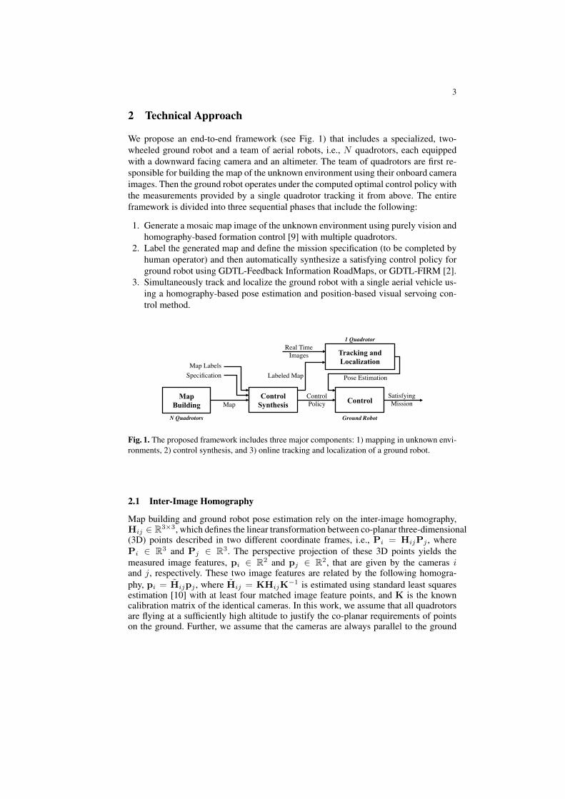
We propose an end-to-end framework (see Fig. 1) that includes a specialized, two-wheeled ground robot and a team of aerial robots, i.e., N quadrotors, each equippedwith a downward facing camera and an altimeter. The team of quadrotors are first re-sponsible for building the map of the unknown environment using their onboard cameraimages. Then the ground robot operates under the computed optimal control policy withthe measurements provided by a single quadrotor tracking it from above. The entireframework is divided into three sequential phases that include the following:
1. Generate a mosaic map image of the unknown environment using purely vision andhomography-based formation control [9] with multiple quadrotors.
2. Label the generated map and define the mission specification (to be completed byhuman operator) and then automatically synthesize a satisfying control policy forground robot using GDTL-Feedback Information RoadMaps, or GDTL-FIRM [2].
3. Simultaneously track and localize the ground robot with a single aerial vehicle us-ing a homography-based pose estimation and position-based visual servoing con-trol method.
Satisfying Mission
Map Building
Control Synthesis Control Map
Tracking and Localization Map Labels
Specification
Control Policy
Real Time Images
Labeled Map Pose Estimation
N Quadrotors Ground Robot
1 Quadrotor
Fig. 1. The proposed framework includes three major components: 1) mapping in unknown envi-ronments, 2) control synthesis, and 3) online tracking and localization of a ground robot.
2.1 Inter-Image Homography
Map building and ground robot pose estimation rely on the inter-image homography,Hij ∈ R3×3, which defines the linear transformation between co-planar three-dimensional(3D) points described in two different coordinate frames, i.e., Pi = HijPj , wherePi ∈ R3 and Pj ∈ R3. The perspective projection of these 3D points yields themeasured image features, pi ∈ R2 and pj ∈ R2, that are given by the cameras iand j, respectively. These two image features are related by the following homogra-phy, pi = H̃ijpj , where H̃ij = KHijK
−1 is estimated using standard least squaresestimation [10] with at least four matched image feature points, and K is the knowncalibration matrix of the identical cameras. In this work, we assume that all quadrotorsare flying at a sufficiently high altitude to justify the co-planar requirements of pointson the ground. Further, we assume that the cameras are always parallel to the ground

4
– as with a hovering quadrotor. In this case, the rectified homography describes thetransformation between two parallel, calibrated camera poses,
Hrij =
cos(ψij) − sin(ψij) −xij
zj
sin(ψij) cos(ψij) − yijzj
0 0 1− zijzj
, (1)
where [xij , yij , zij , ψij ]T ∈ R4 is the estimated parallel pose of camera j in the
frame of camera i. In practice, we guarantee the parallel camera assumption by re-moving the roll and pitch effect of a translating quadrotor from the acquired image,i.e., Hr
ij = RθiRφiK−1H̃ijKRT
φjRTθj
, given the roll, φ, and pitch, θ, of each quadro-tor. We extract the relative position from the last column of Hr
ij , given the altitude ofthe cameras provided by the altimeter, and the relative orientation from the upper 2×2block of Hr
ij .
2.2 Homography-based Formation Control
Homography-based formation control [9] drives the team of quadrotors that generatesthe high fidelity mosaic map image, which is a composite image of the quadrotors’onboard images while in formation. The consensus-based kinematic control laws thatdrive the formation of quadrotors to their desired relative pose, [x∗i,j , y
∗i,j , ψ
∗i,j ]
T , arefunctions of the computed rectified homography from equation (1), i.e.,
wzi = Kw
∑j∈Ni
(arctan
[[Hr
ij ]21
[Hrij ]11
]− ψ∗ij
), (2)
[vxi
vyi
]= Kv
∑j∈Ni
([[Hrij
]13[
Hrij
]23
]−[x∗ijy∗ij
]), (3)
vzi = Kv
∑j∈Ni
(1− [Hr
ij ]33), (4)
where [vxi, vyi , vzi ]
T is the translational velocity control and wzi is the rotational ve-locity control about the z-axis of the quadrotor, i.e., its yaw. Note that the element inrow a and column b of Hr
ij is denoted by [Hrij ]ab. The relative yaw does not affect zij ,
therefore, the relative altitude can be controlled towards zero using [Hrij ]33. The team
produces the mosiac map of the environment when the quadrotors reach the chosenformation that yields sufficient image overlap for accurate pose estimation and largeenough field of view to cover the region of interest in the environment. It is worth not-ing that this component of our solution framework could be omitted if given a highresolution map, such as a satellite image.
2.3 GDTL-FIRM
The GDTL-FIRM algorithm computes the optimal control action for the ground robotunder a GDTL specification given that the previously computed map has been labeled
5
and the specification has been provided. We assume that a human operator labels themap built by the aerial vehicles. Alternately, this labeling could be accomplished au-tomatically by a segmentation and classification algorithm. We utilize the work of [2]to synthesize the control polices for the ground robot with temporal and uncertaintyconstraints. In brief, the sampling-based algorithm generates a transition system in thebelief space and uses local feedback controllers to break the curse of history associatedwith belief space planning. The algorithm is based on Feedback Information RoadMaps(FIRMs), where points are sampled directly in the state space and feedback controllersare used to stabilize the system about nodes in the roadmap, thus inducing a roadmapin the belief space. A product Markov Decision Process (MDP) between the transitionsystem and the Rabin automaton encoding the GDTL task specification is used to com-pute the switching control policies. Finally, the MDP is queried for the existence ofsatisfying control policies of high enough probability.
2.4 Robot Tracking and Localization
The ground robot executes its mission in the environment by traversing the transitionsystem generated in the previous phase while employing an Extended Kalman Filter(EKF) to estimate its position with measurements provided by the dedicated aerial ve-hicle. A localization marker on the ground robot includes two distinctly colored patchesthat aid in estimating its planar position and orientation in the environment frame. Dur-ing localization, the quadrotor first localizes the centroid of each patch in the quadro-tor’s image frame as two image features, (pq1,p
q2). The quadrotor simultaneously calcu-
lates the rectified homography between the quadrotor’s image frame (q) and the mosaicmap image frame (m), i.e., Hr
qm, to estimate the relative pose between the quadro-tor and the map. The quadrotor projects the robot’s pose in the image frame (pq1,p
q2)
to the map frame (pm1 ,pm2 ) using Hr
qm. The quadrotor finally computes the groundrobot’s final pose in the environment frame (e), given by (x, y, θ), by linearly interpo-lating (pm1 ,p
m2 ) with the dimensions of the map image – in pixels – and the known
dimensions of the environment – measured in meters. The centroid of the projected fea-tures yields the position, (x, y), while the orientation, θ, is calculated using the line thatconnects the two projected features.
Meanwhile, a 2D kinematic PBVS controller maneuvers the aerial robot to trackthe ground robot while simultaneously keeping sufficient overlap with the mosaic mapimage for an accurate homography estimation. Recall that the field-of-view of the indi-vidual cameras is not sufficient to view the entire environment, hence the requirementfor the composite map image. Homography-based control drives the quadrotor into adesired position above the environment that is defined by the estimated position ofthe ground robot, (x, y). The quadrotor’s position is further constrained to a rectangle,R = [xmin, xmax] × [ymin, ymax], where the boundaries of R affect the amount ofdesired overlap with the mosaic image. For example, setting the boundaries equal to thedimensions of the environment will drive the quadrotor directly over the ground robot,thus degrading the homography estimate when hovering near the environment’s edges.Conversely, setting the boundaries equal to zero would keep the quadrotor coincidentwith the mosaic image frame and will lose coverage when the ground robot is nearthe edge of the environment. The ideal boundary values for a downward facing camera
6
allows the camera to move just far enough to see the entire environment, i.e.,[xminymin
]= −
[xmaxymax
]=
[we−ewq
2he−ehq
2
], (5)
where (we, he) are the width and height of the environment in meters, (ewq, ehq) arethe dimensions of the quadrotor’s image frame, (wq, hq), after being projected into theenvironment frame. This projection is computed as, ewqehq
A
= AK−1
wqhq1
, (6)
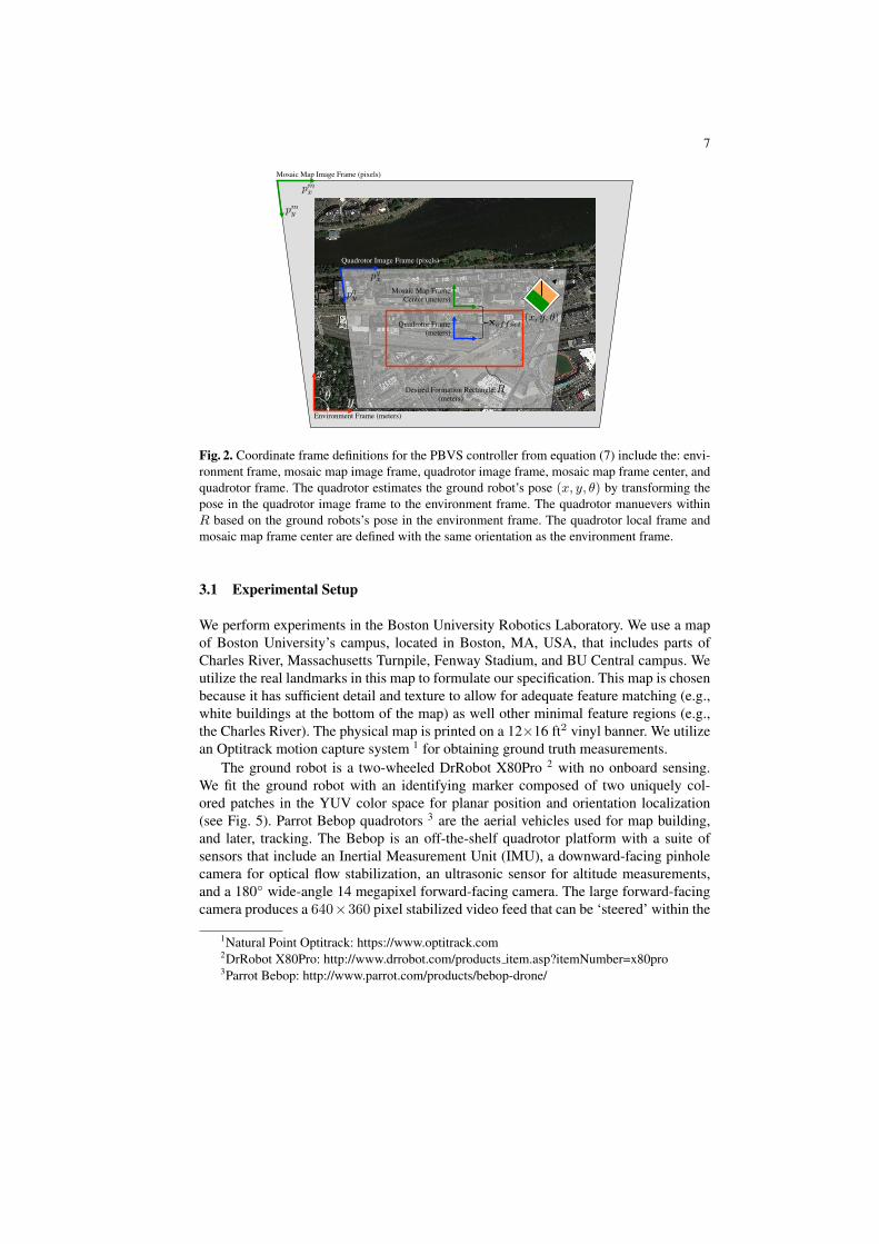
given the camera’s altitude, A, and camera calibration matrix, K. The ideal rectanglesize for our camera (640×360) at the desired experiment altitude of 1.8 meters is ap-proximately 0.85 × 1.45 meters. Unfortunately, our camera is not downward-facing,therefore we expand R to 0.85 × 2.0 meters to ensure proper coverage. Finally, weintroduce an optional offset, xoffset, that measures the center of mosaic map image’svirtual position in space with respect to the quadrotor’s frame. We use an offset 0.75meters in the positive x-direction of the local quadrotor frame (see Fig. 2) to accountfor the forward-facing camera.
The final controller is similar to the homography-based formation controller in Sec-tion 2.2. In fact, the yaw controller of equation (2) and the altitude controller of equa-tion (4) remain the same with a desired relative pose equal to zero. The planar controlvector is calculated as the following,[
vxvy
]= Kv
([[Hrqm
]13[
Hrqm
]23
]−[linint(x, (0, we), (xmin, xmax))− xoffsetlinint(y, (0, he), (ymin, ymax))− yoffset
]), (7)
where linint(·) is the linear interpolation function that transforms the ground robot’senvironmental position into the quadrotor’s desired position within R.
3 Results and Experiments
We validate all three phases of this framework by executing a complete mission ex-periment with a heterogeneous team of autonomous robots. The phases are completedin the order specified in Section 2 due to the dependence on the results from previousphases. We first detail our map building results with a mosaic map that is generated us-ing the homography-based formation control and two quadrotors with cameras that donot have access to GPS. GDTL-FIRM synthesizes the control policy for a ground robotwith nonlinear unicycle dynamics in the environment for a GDTL specification overbelief states associated with the measurement of the robot’s position. Finally, a quadro-tor successfully tracks and localizes the ground robot while it completes the previouslydefined mission.
7
Environment Frame (meters)
Quadrotor Image Frame (pixels)
Mosaic Map Image Frame (pixels)
Mosaic Map Frame Center (meters)
Quadrotor Frame (meters)
y
xDesired Formation Rectangle,
(meters)
pqx
pqy
pmy
pmx
R
xoffset(x, y, �)
✓
Fig. 2. Coordinate frame definitions for the PBVS controller from equation (7) include the: envi-ronment frame, mosaic map image frame, quadrotor image frame, mosaic map frame center, andquadrotor frame. The quadrotor estimates the ground robot’s pose (x, y, θ) by transforming thepose in the quadrotor image frame to the environment frame. The quadrotor manuevers withinR based on the ground robots’s pose in the environment frame. The quadrotor local frame andmosaic map frame center are defined with the same orientation as the environment frame.
3.1 Experimental Setup
We perform experiments in the Boston University Robotics Laboratory. We use a mapof Boston University’s campus, located in Boston, MA, USA, that includes parts ofCharles River, Massachusetts Turnpile, Fenway Stadium, and BU Central campus. Weutilize the real landmarks in this map to formulate our specification. This map is chosenbecause it has sufficient detail and texture to allow for adequate feature matching (e.g.,white buildings at the bottom of the map) as well other minimal feature regions (e.g.,the Charles River). The physical map is printed on a 12×16 ft2 vinyl banner. We utilizean Optitrack motion capture system 1 for obtaining ground truth measurements.
The ground robot is a two-wheeled DrRobot X80Pro 2 with no onboard sensing.We fit the ground robot with an identifying marker composed of two uniquely col-ored patches in the YUV color space for planar position and orientation localization(see Fig. 5). Parrot Bebop quadrotors 3 are the aerial vehicles used for map building,and later, tracking. The Bebop is an off-the-shelf quadrotor platform with a suite ofsensors that include an Inertial Measurement Unit (IMU), a downward-facing pinholecamera for optical flow stabilization, an ultrasonic sensor for altitude measurements,and a 180◦ wide-angle 14 megapixel forward-facing camera. The large forward-facingcamera produces a 640×360 pixel stabilized video feed that can be ‘steered’ within the
1Natural Point Optitrack: https://www.optitrack.com2DrRobot X80Pro: http://www.drrobot.com/products item.asp?itemNumber=x80pro3Parrot Bebop: http://www.parrot.com/products/bebop-drone/

8
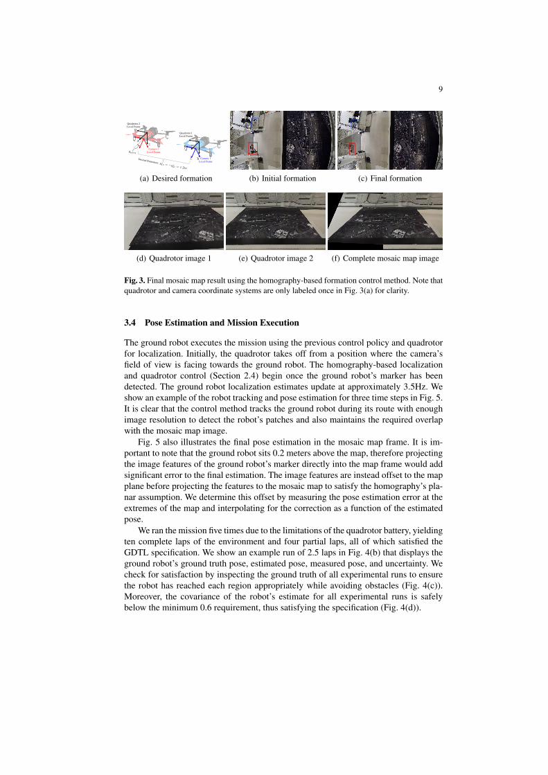
field-of-view of the wide-angle lens to produce a ‘virtual camera’ video feed. We po-sition the virtual camera at the maximum angle of θbebop measured about the y-axis ofthe quadrotor (see Fig. 3(a)), where θbebop ≈ 50◦, and rectify the image for this angle.
The Robot Operating System (ROS) [11] handles all communication on a local areanetwork via Wi-Fi. We control the quadrotors from a base station computer runningthe ROS Bebop Autonomy package [12] which incorporates Parrot’s open-source SDK.The computer also acquires and processes image frames from the quadrotors’ real-time video stream via the OpenCV libraries [13]. Independent ROS nodes handle theindividual quadrotors for the formation flight, demonstrating the distributed control.Independent ROS nodes also handle the quadrotor and ground robot control during thetracking phase. In this phase, separate quadrotor nodes handle the image processing forrobot localization, pose estimation via homography, and the control. The ground robotnode executes the local control and EKF estimation of the ground robot given its poseestimate and nonlinear dynamics. All vision computations are performed on an Ubuntu14.04 machine with an Intel Core i7 CPU at 2.4 GHz and 8GB RAM.
3.2 Formation Control and Map Generation
We utilize a team of two quadrotors to reach a desired formation where, y∗1,2 = −y∗2,1 =1.2 m, and all other desired relative poses are set to zero (see Fig. 3(a)). This formationis carefully chosen because it ensures the pair of aerial cameras have enough overlapfor accurate relative pose estimation while guaranteeing a complete view of the envi-ronment. All quadrotors are flown to a desired height of 1.8 meters. The quadrotorsreach the desired formation (Fig. 3(c)) from the initial conditions (Fig. 3(b)) in approx-imately 15 seconds. From this point, the user has the ability to control one vehicle inthe formation to fine tune the result of the online mosaic map, which is displayed atapproximately 2.5Hz. In this experiment, the operator maneuvers quadrotor 1 until theleft edge of the map is completely visible and then releases it to autonomous controlagain. Meanwhile, the formation control law in Section 2.2 controls quadrotor 2. Theonboard images at the final desired formation (Figs. 3(d)- 3(e)) were used to generatethe final mosaic map image shown in Fig. 3(f).
3.3 GDTL-FIRM
The specification for the ground robot is encoded with GDTL and is given as the fol-lowing: “Always avoid all obstacles, i.e., Charles river and Massachusetts Turnpike.Always eventually visit Kenmore Square, Marsh Plaza, Audubon Circle, and FenwayStadium. From Kenmore Square or Marsh Plaza, Bridge2 (St Mary’s St) can not beused to visit Audubon Circle or Fenway Stadium. From Audubon Circle or FenwayStadium, Bridge1 (Beacon Ave or Brookline Ave) can not be used to visit KenmoreSquare or Marsh Plaza. Always keep uncertainty about the robot’s pose below 0.9 m2,and on bridges, the uncertainty must be below 0.6 m2, where uncertainty is measured asthe trace of the estimation pose covariance matrix.” Fig. 4(a) shows the resulting tran-sition system and control policy, computed by the algorithm from [2]. The transitionsystem has 35 nodes and 226 edges while the product automaton has 316 nodes and3274 edges. The algorithm executed in approximately 62.24 seconds.
9
y⇤12 = �y⇤
21 = 1.2m
Desired Formation:
Quadrotor 1 Local Frame
Camera 2 Local Frame
Quadrotor 2 Local Frame
Camera 1 Local Frame
x
y
zx
yz
✓bebop
(a) Desired formation
Quadrotor 1
Quadrotor 2
(b) Initial formation
Quadrotor 1
Quadrotor 2
Quadrotor 1
Quadrotor 2
(c) Final formation
(d) Quadrotor image 1 (e) Quadrotor image 2 (f) Complete mosaic map image
Fig. 3. Final mosaic map result using the homography-based formation control method. Note thatquadrotor and camera coordinate systems are only labeled once in Fig. 3(a) for clarity.
3.4 Pose Estimation and Mission Execution
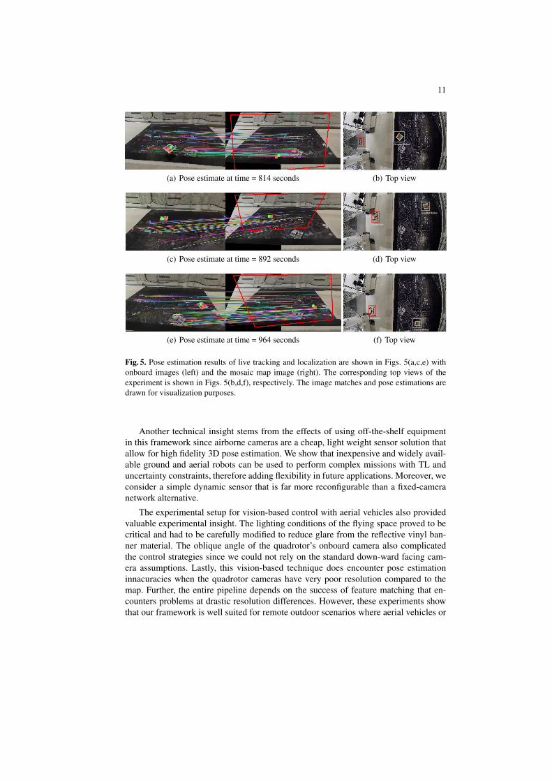
The ground robot executes the mission using the previous control policy and quadrotorfor localization. Initially, the quadrotor takes off from a position where the camera’sfield of view is facing towards the ground robot. The homography-based localizationand quadrotor control (Section 2.4) begin once the ground robot’s marker has beendetected. The ground robot localization estimates update at approximately 3.5Hz. Weshow an example of the robot tracking and pose estimation for three time steps in Fig. 5.It is clear that the control method tracks the ground robot during its route with enoughimage resolution to detect the robot’s patches and also maintains the required overlapwith the mosaic map image.
Fig. 5 also illustrates the final pose estimation in the mosaic map frame. It is im-portant to note that the ground robot sits 0.2 meters above the map, therefore projectingthe image features of the ground robot’s marker directly into the map frame would addsignificant error to the final estimation. The image features are instead offset to the mapplane before projecting the features to the mosaic map to satisfy the homography’s pla-nar assumption. We determine this offset by measuring the pose estimation error at theextremes of the map and interpolating for the correction as a function of the estimatedpose.
We ran the mission five times due to the limitations of the quadrotor battery, yieldingten complete laps of the environment and four partial laps, all of which satisfied theGDTL specification. We show an example run of 2.5 laps in Fig. 4(b) that displays theground robot’s ground truth pose, estimated pose, measured pose, and uncertainty. Wecheck for satisfaction by inspecting the ground truth of all experimental runs to ensurethe robot has reached each region appropriately while avoiding obstacles (Fig. 4(c)).Moreover, the covariance of the robot’s estimate for all experimental runs is safelybelow the minimum 0.6 requirement, thus satisfying the specification (Fig. 4(d)).

10
0 1 2 3 4 5x [m]
0.0
0.5
1.0
1.5
2.0
2.5
3.0
3.5
y [m
]
(a) Transition system and policy
0 1 2 3 4 5x [m]
0.0
0.5
1.0
1.5
2.0
2.5
3.0
3.5
y [m
]
(b) Results from one experimental run (time800-1050 seconds)
0 1 2 3 4 5x [m]
0.0
0.5
1.0
1.5
2.0
2.5
3.0
3.5
y [m
]
(c) Ground truth for ten laps
0 200 400 600 800 1000 1200 1400t [sec]
0.10
0.12
0.14
0.16
0.18
0.20
tr(P
) [m
2]
(d) Covariance for ten laps
Fig. 4. FIRM-GDTL results plotted over the ground truth environment image. Fig. 4(a) shows thetransition system in white and the policy in orange. Fig. 4(b) shows the ground truth in green, themeasurement in yellow, the estimated pose in red, and the covariance ellipses in blue. Fig. 4(c)shows the ground truth in green for all runs. Fig. 4(d) shows the covariance for all runs. The spikesin covariance indicate the beginning of a new run after a quadrotor battery had been replaced. Weinitialize the covariance to an arbitrarily large value at time step 0 that drastically decreases withthe first pose measurement from the quadrotor at time step 1.
4 Conclusion
The main experimental insight gained from this work is how to feasibly break the depen-dence on external positioning information while controlling robots under TL specifica-tions. Specifically, we are interested in studying the satisfaction of GDTL specificationsby (ground) robots operating under uncertainty. Encoding specifications with GDTL isadvantageous because it defines performance goals for the uncertainty of the system,allowing us to complete high-level missions under noisy measurements. This work alsogives insight into the formulation of a mobile vision-based sensing method for controlunder TL specifications.
11
(a) Pose estimate at time = 814 seconds
QuadrotorGround Robot
(b) Top view
(c) Pose estimate at time = 892 seconds
Quadrotor
Ground Robot
(d) Top view
(e) Pose estimate at time = 964 seconds
Quadrotor
Ground Robot
(f) Top view
Fig. 5. Pose estimation results of live tracking and localization are shown in Figs. 5(a,c,e) withonboard images (left) and the mosaic map image (right). The corresponding top views of theexperiment is shown in Figs. 5(b,d,f), respectively. The image matches and pose estimations aredrawn for visualization purposes.
Another technical insight stems from the effects of using off-the-shelf equipmentin this framework since airborne cameras are a cheap, light weight sensor solution thatallow for high fidelity 3D pose estimation. We show that inexpensive and widely avail-able ground and aerial robots can be used to perform complex missions with TL anduncertainty constraints, therefore adding flexibility in future applications. Moreover, weconsider a simple dynamic sensor that is far more reconfigurable than a fixed-cameranetwork alternative.
The experimental setup for vision-based control with aerial vehicles also providedvaluable experimental insight. The lighting conditions of the flying space proved to becritical and had to be carefully modified to reduce glare from the reflective vinyl ban-ner material. The oblique angle of the quadrotor’s onboard camera also complicatedthe control strategies since we could not rely on the standard down-ward facing cam-era assumptions. Lastly, this vision-based technique does encounter pose estimationinnacuracies when the quadrotor cameras have very poor resolution compared to themap. Further, the entire pipeline depends on the success of feature matching that en-counters problems at drastic resolution differences. However, these experiments showthat our framework is well suited for remote outdoor scenarios where aerial vehicles or
12
satellite imagery could serve as the map and only camera-outfitted aerial vehicles arerequired for localization.
5 Acknowledgements
E. Cristofalo was supported in part by the 2015 National Defense Science and Engineer-ing Graduate (NDSEG) fellowship. This work was also supported by US grants NSFCNS-1330008, NSF IIS-1350904, NSF NRI-1426907, NSF CMMI-1400167, ONR N00014-12-1-1000, and Spanish projects DPI2015-69376-R (MINECO/FEDER) and SIRENA(CUD2013-05). We are grateful for this support.
References
1. Hsieh, M.A., Cowley, A., Keller, J.F., Chaimowicz, L., Grocholsky, B., Kumar, V., Taylor,C.J., Endo, Y., Arkin, R.C., Jung, B., et al.: Adaptive teams of autonomous aerial and groundrobots for situational awareness. Journal of Field Robotics 24(11-12) (2007) 991–1014
2. Vasile, C.I., Leahy, K., Cristofalo, E., Jones, A., Schwager, M., Belta, C.: Control in be-lief space with temporal logic specifications. In: Proceedings of the 2016 Conference onDecision and Control (CDC), IEEE (2016) To Appear.
3. Vaughan, R.T., Sukhatme, G.S., Mesa-Martinez, F.J., Montgomery, J.F.: Fly spy:Lightweight localization and target tracking for cooperating air and ground robots. In: Dis-tributed autonomous robotic systems 4. Springer (2000) 315–324
4. Grocholsky, B., Keller, J., Kumar, V., Pappas, G.: Cooperative air and ground surveillance.Robotics & Automation Magazine 13(3) (2006) 16–25
5. Forster, C., Pizzoli, M., Scaramuzza, D.: Air-ground localization and map augmentationusing monocular dense reconstruction. In: Proceedings of the 2013 IEEE/RSJ InternationalConference on Intelligent Robots and Systems (IROS), IEEE (2013) 3971–3978
6. Thrun, S., Leonard, J.J.: Simultaneous localization and mapping. In: Springer handbook ofrobotics. Springer (2008) 871–889
7. Newcombe, R.A., Lovegrove, S.J., Davison, A.J.: Dtam: Dense tracking and mapping inreal-time. In: Proceedings of the 2011 International Conference on Computer Vision (ICCV),IEEE (2011) 2320–2327
8. Benhimane, S., Malis, E.: Homography-based 2d visual servoing. In: Proceedings of the2006 International Conference on Robotics and Automation (ICRA), IEEE (2006) 2397–2402
9. Montijano, E., Cristofalo, E., Zhou, D., Schwager, M., Sagues, C.: Vision-based distributedformation control without an external positioning system. Transactions on Robotics 32(1)(2016) 339–351
10. Ma, Y., Soatto, S., Kosecka, J., Sastry, S.S.: An invitation to 3-d vision: from images togeometric models. Volume 26. Springer Science & Business Media (2012)
11. Quigley, M., Conley, K., Gerkey, B., Faust, J., Foote, T., Leibs, J., Wheeler, R., Ng, A.Y.:Ros: an open-source robot operating system. In: ICRA workshop on open source software.Volume 3. (2009) Page 5
12. Monajjemi, M.: Bebop autonomy. https://github.com/AutonomyLab/bebop_autonomy (2015)
13. Bradski, G., et al.: The opencv library. Doctor Dobbs Journal 25(11) (2000) 120–126