
Local Heat Transfer Dependency on Thermal Boundary ... · The heat flux distribution along the...
11
Beni Cukurel 1,2 e-mail: [email protected] Tony Arts e-mail: [email protected] von Karman Institute for Fluid Dynamics, Turbomachinery Department, Chausse ´e de Waterloo, 72, B-1640 Rhode-St-Genese, Belgium Local Heat Transfer Dependency on Thermal Boundary Condition in Ribbed Cooling Channel Geometries The present study is geared toward quantifying the effects of imposed thermal boundary condition in cooling channel applications. In this regard, tests are conducted in a generic passage, with evenly distributed rib type perturbators at 90 deg, with a 30% passage blockage ratio and pitch-to-height ratio of 10. Uniform heat-flux is imposed on the exter- nal side of the slab which provides Biot number and solid-to-fluid thermal conductivity ratio around 1 and 600, respectively. Through infrared thermometry measurements over the wetted surface and via an energy balance within the solid, conjugate heat transfer coefficients are calculated over a single rib-pitch. The local heat extraction is demon- strated to be a strong function of the conduction effects, observed more dominantly in the rib vicinity. Moreover, the aero-thermal effects are investigated by comparing the find- ings with analogous aerodynamic literature, enabling heat transfer distributions to be associated with distinct flow structures. Furthermore, the results are contrasted with the iso-heat-flux wetted boundary condition test case. Neglecting the thermal boundary con- dition dependence, and thus the true thermal history of the boundary layer, is demon- strated to produce large errors in heat transfer predictions. [DOI: 10.1115/1.4024494] Keywords: conjugate heat transfer, cooling channel, convection, infrared thermography, ribbed channel, thermal boundary condition Introduction Both numerical and experimental investigations of heat transfer enhancing cooling geometries should reproduce the thermal boundary conditions that reflect the application environment. Most studies do not address the influence of the thermal boundary condition. However, in case of large spatial thermal gradients and/ or geometrical asperities, the wall temperature distribution’s impact on heat transfer may be large. In purely convective mod- els, where uniform temperature or uniform heat flux is imposed along the wetted surface, the thermal boundary condition is clearly not realistic. On the contrary, in the conjugate heat transfer case, where the effects of the solid domain conduction are coupled with the convection over the surface (i.e., the thermal history of the boundary layer is accurately modeled), no constraint is enforced at the solid-fluid interface, except thermal equilibrium and heat flux continuity. The methodology of conjugate heat transfer analysis presents the opportunity to accurately model the true heat transfer mechanisms. The present research effort is devoted to a deeper understanding of the conjugate heat transfer phenomenon by conducting experi- ments toward fundamental understanding through generic cooling channel models. This study is among the few comparative heat transfer studies, confronting the results of a fully coupled conju- gate investigation with purely convective iso-heat-flux boundary condition data, and exemplifies the pioneering experimental efforts to include the effects of conduction coupling in forced con- vection applications. In addition, the different heat transfer enhancement effects of various aerodynamic flow structures, as acquired by particle image velocimetry (PIV) experiments con- ducted a priori, are investigated. In this regard, a uniform heat flux boundary condition is applied at the external side of a geometrically scaled test section model of a simplified turbine internal cooling channel, Fig. 1(a). The inves- tigation focuses on surface heat flux calculations through local temperature measurements performed by infrared thermography. The heat flux distribution along the wetted side of the slab, com- puted from an energy balance within the metal domain, ultimately yields the Nusselt number distributions over the ribbed surface. Fig. 1 Conjugate (a) versus convective (b) heat transfer 1 Present address: The Turbo and Jet Engine Laboratory, Faculty of Aerospace Engineering, Technion, Israel Institute of Technology, Haifa 32000, Israel. 2 Corresponding author. Contributed by the Heat Transfer Division of ASME for publication in the JOURNAL OF HEAT TRANSFER. Manuscript received April 17, 2012; final manuscript received January 17, 2013; published online September 11, 2013. Assoc. Editor: Roy E. Hogan. Journal of Heat Transfer OCTOBER 2013, Vol. 135 / 101001-1 Copyright V C 2013 by ASME Downloaded From: http://heattransfer.asmedigitalcollection.asme.org/ on 10/10/2013 Terms of Use: http://asme.org/terms
Transcript of Local Heat Transfer Dependency on Thermal Boundary ... · The heat flux distribution along the...
Beni Cukurel1,2
e-mail: [email protected]
Tony Artse-mail: [email protected]
von Karman Institute for Fluid Dynamics,
Turbomachinery Department,
Chaussee de Waterloo, 72,
B-1640 Rhode-St-Genese, Belgium
Local Heat TransferDependency on ThermalBoundary Condition in RibbedCooling Channel GeometriesThe present study is geared toward quantifying the effects of imposed thermal boundarycondition in cooling channel applications. In this regard, tests are conducted in a genericpassage, with evenly distributed rib type perturbators at 90 deg, with a 30% passageblockage ratio and pitch-to-height ratio of 10. Uniform heat-flux is imposed on the exter-nal side of the slab which provides Biot number and solid-to-fluid thermal conductivityratio around 1 and 600, respectively. Through infrared thermometry measurements overthe wetted surface and via an energy balance within the solid, conjugate heat transfercoefficients are calculated over a single rib-pitch. The local heat extraction is demon-strated to be a strong function of the conduction effects, observed more dominantly in therib vicinity. Moreover, the aero-thermal effects are investigated by comparing the find-ings with analogous aerodynamic literature, enabling heat transfer distributions to beassociated with distinct flow structures. Furthermore, the results are contrasted with theiso-heat-flux wetted boundary condition test case. Neglecting the thermal boundary con-dition dependence, and thus the true thermal history of the boundary layer, is demon-strated to produce large errors in heat transfer predictions. [DOI: 10.1115/1.4024494]
Keywords: conjugate heat transfer, cooling channel, convection, infrared thermography,ribbed channel, thermal boundary condition
Introduction
Both numerical and experimental investigations of heat transferenhancing cooling geometries should reproduce the thermalboundary conditions that reflect the application environment.Most studies do not address the influence of the thermal boundarycondition. However, in case of large spatial thermal gradients and/or geometrical asperities, the wall temperature distribution’simpact on heat transfer may be large. In purely convective mod-els, where uniform temperature or uniform heat flux is imposedalong the wetted surface, the thermal boundary condition isclearly not realistic. On the contrary, in the conjugate heat transfercase, where the effects of the solid domain conduction are coupledwith the convection over the surface (i.e., the thermal history ofthe boundary layer is accurately modeled), no constraint isenforced at the solid-fluid interface, except thermal equilibriumand heat flux continuity. The methodology of conjugate heattransfer analysis presents the opportunity to accurately model thetrue heat transfer mechanisms.
The present research effort is devoted to a deeper understandingof the conjugate heat transfer phenomenon by conducting experi-ments toward fundamental understanding through generic coolingchannel models. This study is among the few comparative heattransfer studies, confronting the results of a fully coupled conju-gate investigation with purely convective iso-heat-flux boundarycondition data, and exemplifies the pioneering experimentalefforts to include the effects of conduction coupling in forced con-vection applications. In addition, the different heat transfer
enhancement effects of various aerodynamic flow structures, asacquired by particle image velocimetry (PIV) experiments con-ducted a priori, are investigated.
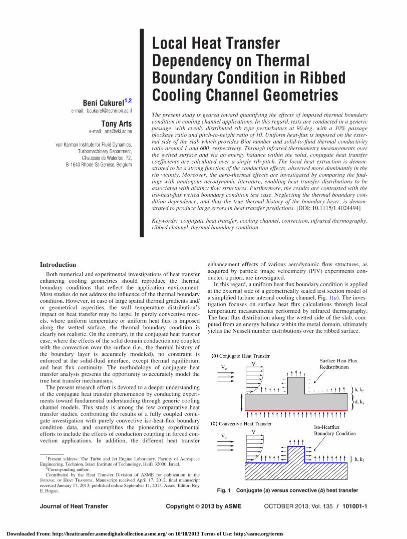
In this regard, a uniform heat flux boundary condition is appliedat the external side of a geometrically scaled test section model ofa simplified turbine internal cooling channel, Fig. 1(a). The inves-tigation focuses on surface heat flux calculations through localtemperature measurements performed by infrared thermography.The heat flux distribution along the wetted side of the slab, com-puted from an energy balance within the metal domain, ultimatelyyields the Nusselt number distributions over the ribbed surface.
Fig. 1 Conjugate (a) versus convective (b) heat transfer
1Present address: The Turbo and Jet Engine Laboratory, Faculty of AerospaceEngineering, Technion, Israel Institute of Technology, Haifa 32000, Israel.
2Corresponding author.Contributed by the Heat Transfer Division of ASME for publication in the
JOURNAL OF HEAT TRANSFER. Manuscript received April 17, 2012; final manuscriptreceived January 17, 2013; published online September 11, 2013. Assoc. Editor: RoyE. Hogan.
Journal of Heat Transfer OCTOBER 2013, Vol. 135 / 101001-1Copyright VC 2013 by ASME
Downloaded From: http://heattransfer.asmedigitalcollection.asme.org/ on 10/10/2013 Terms of Use: http://asme.org/terms
Similarity Analysis
Considering the fluid flow along a nonadiabatic passage whereconvection-conduction coupled (conjugate) heat transfer phenom-ena takes place, making explicit use of the Buckingham-Pi theo-rem, the relation of the primary variables among each another canbe reduced to a relation between the base quantities, yielding thedimensionless form
f Re;Pr;Ec; T1=DT;Nu;K;Bið Þ ¼ 0 (1)
where Ec, T1/DT, Nu, K, Bi are the Eckert number, the scaled rel-ative bulk flow temperature, the Nusselt number, the solid-fluidthermal conductivity ratio, and the Biot number.
The relative bulk flow temperature, T1/DT, is experimentallyfound to have only a small influence and thus is neglected. This isa fair assumption when the physical properties of the fluid do notvary significantly with respect to temperature and small tempera-ture differences [1]. The Eckert number is a measure of the vis-cous dissipation of the flow, arising in high-speed heat transferproblems. Especially for low speed applications, the relative im-portance of the kinetic energy with respect to the enthalpy isfound to be very small, which largely reduces the influence of thisdimensionless quantity. Moreover, for a given gas in a confinedtemperature range, the variation of Pr is negligible. Therefore, onecan infer that a nondimensional temperature distribution in ascaled test facility of a geometrically similar internal cooling cav-ity proves to be aero-thermally similar, when Re, K, and Bi aremaintained
Nu ¼ f Re;K;Bið Þ (2)
Thus, for a conjugate problem with fixed geometric and aerody-namic constraints, the heat transfer depends not only on the localflow but also on the solid and air thermal conductivities, as wellas on the thickness of the material, Fig. 1(a). In contrast, if thechoice of the thermal boundary condition is assumed to have anegligible effect on the surface heat transfer, the convective prob-lem would diminish its solid dependency, where Nu is only afunction of Re, Fig. 1(b).
The intensity of the conjugate heat transfer effect is in partdetermined by the solid to fluid thermal conductivity ratio, K. Inthe case of a given wall to fluid temperature head variation, thisratio largely specifies the heat transfer distribution, driven by thenonisothermicity of the surface. In turn, the Biot number deter-mines the rate of heat transfer and incorporates the flux re-allocation effects. In both limiting cases, Bi!1 and Bi!0, theconjugate problem degenerates. In other words, a low Biot num-ber corresponds to a high convective thermal resistance, and thusa high temperature gradient in the fluid. Whereas in the case of ahigh Biot number, the largest temperature gradient will be in thesolid and the wall temperature will be close to the fluid tempera-ture. In either case, one of the thermal resistances is negligible,which concludes that the greatest conduction-convection couplingeffect should be when both resistances are of the same magnitude,Bi �1.
The Biot number, used as a criterion to estimate the importanceof conjugate analysis, can be presented in various suitable formsdepending on the application. Alternative formulations, character-izing the body–fluid thermal resistances, include the Brun numberBrx¼ (d/x)K�1(Pr Rex)
1/3 [2], which gives a measure of the ther-mal resistances of the plate to that of the laminar boundary layer,and the conjugate Peclet number Pe*¼K�1Pe1/3 [3], which is theratio of the rate of advection by the flow to the rate of diffusion.
Conjugate Heat Transfer
The conjugate heat transfer problem considers the thermalinteraction between a body and a fluid flowing over it, as a resultof which a particular temperature distribution establishes on the
interface. This temperature field determines the heat flux distribu-tion, and thus the associated local heat transfer. Hence, from theperspective of the fluid, the properties of heat transfer of any con-jugate problem are actually the same as its convective counterpartso long as an identical nonuniform temperature field could beimposed along the wetted surface. Thus, in general, the theory ofconjugate heat transfer is in fact the theory of an arbitrary noniso-thermal surface, but the temperature distribution on the interfaceis unknown a priori.
The problem of generally unknown temperature and heat fluxdistributions at the solid-fluid interface, determined by thecoupled solution of the thermofluid dynamic equations in the fluidand the energy equation in the solid, is defined as conjugate heattransfer problem [4]. Fundamental analytical studies, utilizingincompressible laminar fluid flow along a flat plate which is uni-formly heated at the external side, highlight the heat transfer de-pendence on thermal conductivity ratio [5,6]. Simplifiedexpressions for the calculation of surface temperature, heat fluxand Nusselt number, reduce the dependency to a function of thelocal Brun number, where Reynolds number is based on the free-stream velocity [7]. The critical proposed Brun number is in theorder of 0.1; and for higher values, the results acquired by usingconjugate and isothermal boundary conditions vary more than 5%[7].
Laminar flow inside a circular tube geometry was studied ana-lytically [8] and numerically [9]. Axial conduction in the wall wasfound to lower the Nusselt number when compared to theoreticalpredictions in the absence of axial conduction, and to induce aheat redistribution effect. Specifically, a global 10% Nusselt num-ber reduction, while local heat flux deviations up to 100%, isobserved when the interface boundary condition is switched fromiso-heat-flux (convective) to conjugate [9]. Moreover, whenapplying a constant heat flux to the external surface of the plate,the effect of wall conduction on the heat transfer augments withan increase of the solid-fluid thermal conductivity ratio (K) [8].
Due to the complexity of the conjugate problem, fundamentalstudies are commonly performed by numerical methods employ-ing approximate solutions such as Green’s functions [10,11].Studies on a uniform shear laminar thin flat plate with varyingthermal conductivity ratio, modeling the conjugate heat transferfrom discrete rectangular heat sources, resulted in a relation wherethe Nusselt number is demonstrated to be a power function of theconjugate Peclet number [10]. The significance of solid conduc-tion versus convection through the fluid was investigated, report-ing low Peclet numbers to correspond to dominant conductionwhile Pe around 500 to indicate prevailing convection [10]. In therange of Pe from 5 to 500, the Nusselt number is reported to be upto 25% lower in the case of K¼ 10 (conjugate) compared to theadiabatic case of K¼ 0 (convective) [11].
Analytical studies on the laminar flow over a flat plate, which isheated at one side and insulated on the other side, have been car-ried out by Dorfman [12,13]. His findings highlight the role oftemperature head gradients on local heat transfer. While increas-ing temperature heads (flow approaches from insulated side) cor-responds to augmented heat transfer coefficients, the contrary caseof decreasing temperature heads leads to lower than isothermalboundary condition heat transfer [13–15]. Moreover, for a surfaceat a temperature higher than the surrounding fluid, if the wall tem-perature increases in the flow direction (increasing temperaturehead), the descended layers of fluid at the adjoining wall comeinto contact with the increasingly hotter wall, yielding a local tem-perature augmentation within these layers. Consequentially, thecross-sectional temperature gradients near the wall turn out to begreater than in the case of constant wall temperature, which leadsto higher than isothermal surface heat transfer coefficients. In con-trast, for the case of decreasing surface temperature in the flowdirection, the cross-sectional temperature gradients near the wall,along with the associated heat transfer coefficients, are less thanthose for an isothermal surface, and may become zero if thestreamlined surface is sufficiently long [14]. In addition, it is
101001-2 / Vol. 135, OCTOBER 2013 Transactions of the ASME
Downloaded From: http://heattransfer.asmedigitalcollection.asme.org/ on 10/10/2013 Terms of Use: http://asme.org/terms

important to note that the iso-heat flux boundary condition is aNusselt number upper bound over the iso-thermal interfaceboundary condition. As a consequence, for a heated plate ofincreasing temperature head, all conjugate Nusselt number distri-butions must lay within the two cases [8]. Furthermore, in general,at increased levels of turbulence and for higher Reynolds andPrandtl numbers, the effect of nonisothermicity decreases monoto-nously [14].
A more specific numerical study focusing on the conjugateeffects over the rib indicated that for Reynolds numbers below2000 and K¼ 1, the obstacle behaves as a thermal insulator forthe air flow [16]. As the thermal conductivity ratio increases, byorders of magnitude, the variations in surface temperaturedecrease. On a similar investigation with Pr¼ 0.71, the change inthermal conductivity ratio from the isothermal case to the conju-gate case of K¼ 1 resulted in an average Nusselt number devia-tion of 32% [17].
Flow Over a Backward Facing Step
When the channel cross section is abruptly enlarged in the pres-ence of a rib, the downstream turbulent flow exhibits a number ofcomplex flow features such as reversal and recovery, turbulentmixing, regions of reattachment, and eventually redevelopingboundary layers.
The region of separated flow in the wake, between the backface and the reattachment line, is occupied by the recirculationregion (in a time averaged sense). The exact location of reattach-ment, where the wall near flow initially begins to realign with thesurface, is regarded as a key parameter for the separated flow.Experiments reported the near wall flow region to be substantiallydifferent from an ordinary boundary layer [18,19].
When the flow passes a rib obstacle, a free shear layer is formedat the sharp corner due to the interaction between the separatedmainstream flow and the reverse flow in the recirculation regiondownstream. This free shear layer differs substantially from an or-dinary mixing plane due to its high turbulence level [20], whichalso causes a gradual augmentation of its size at an increased dis-tance from the rib [21]. In the region of flow reattachment, theseparated shear layer curves sharply downward and impinges onthe wall. When subjected to the effects of stabilizing curvatureand a strong interaction with the wall, the shear layer is substan-tially split into two fractions [21,22]. Since the energy of the firstpart does not suffice to overcome the strong adverse pressure gra-dient, it is deflected upstream; being reversed, it forms the recircu-lating flow region. The second part of the shear layer is carriedaway downstream, and contributes to the growth of a new sub-boundary layer reattached to the wall [21].
In backward facing step studies, considering the effects ofboundary layer states at separation (laminar/turbulent), thereexists a sudden large elongation of the reattachment length fromlaminar to transitional flows, followed by a gradual decreasewithin the transitional regime. Toward fully turbulent flow, the de-pendency is observed to be much weaker [22–25]. In addition, anaugmentation in free-stream turbulence level is reported to yielddecreased reattachment lengths [23]. Moreover, as free-streamReynolds number increases, an elongation of the separation regionoccurs, such that an augmentation of ReDh from 200 to 2000 isobserved to double the reattachment length [16].
Regarding heat transfer in backward-facing step geometries, theNusselt number within the reattachment zone is controlled by theturbulence level near the wall. The local turbulence levels are aug-mented compared to an ordinary boundary layer, and in turn resultin a proportionally larger Nusselt number [20]. Further down-stream, a steady gradual Nusselt number decrease is observed andcoincides with the growth of the thermal boundary layer followingreattachment [26].
The direct relation of flow reattachment region with local heattransfer distribution has been extensively studied in literature. Thelocal Nusselt number distribution is typically characterized by an
initial increase within the separation bubble, followed by a peakin the vicinity of the reattachment region [20,27]. The maximumin the streamwise local Nusselt number profile, xmax, has beenconsidered a significant indication for the location of the reattach-ment point, xR, commonly defined by the change of sign in skinfriction coefficient. However, in literature, there appears to behigh inconsistency in the predicted relation between the locationsof xmax and xR [28]. While it is generally assumed that the loca-tions of maximum heat transfer and reattachment coincide, this isan exceptional case [28].
Sparrow et al. [28] indicated that one of the major influencesregarding the relationship between xmax and xR is believed todepend on the separation bubble aspect ratio. With an increase inReynolds number, a significant elongation of the separation bub-ble occurs, evidenced by experiments yielding to doubled reat-tachment length with Re augmentation from 200 to 2000 [16].Furthermore, xmax is observed to be greater than xR for short bub-bles (xR/H< 4) and xmax< xR for relatively long bubbles (xR/H> 7) [28]. This is supported by literature indicating laminarflows to mostly exhibit xmax> xR [29], and turbulent experimentsdetermining the location of maximum heat transfer coefficient tobe upstream of the reattachment point [20,27,30]. Interestingly,for moderate bubble sizes, Sherwood and Nusselt numbers exhib-ited a double peak [27,31]. This appears to be consistent with theobserved peaks in fluctuating wall shear component and turbu-lence intensity upstream and downstream of the reattachment[20,25,26]. In addition, conjugate numerical studies on backward-facing step flow indicated the peak in Nusselt number in the reat-tachment region to shift further downstream and increase in mag-nitude with increased thermal conductivity ratio [31].
Moreover, there have been significant efforts to relate the aero-dynamic quantities with local heat transfer. Expressed in terms ofthe quantitative dependency between heat transfer and shearstress, the Reynolds Analogy presents a fundamental relationshipfor laminar boundary layers, relating Nusselt number linearly withskin friction coefficient and Reynolds number. Moreover, for cer-tain specific applications, the Reynolds analogy is extended tomore complex problems of turbulent flows. However, in the caseof flow over a backward-facing step geometry, such an analogy isdemonstrated to fail [32], to the extent that a maximum Stantonnumber may be at a point where skin-friction coefficient is zero[20]. Interestingly, a Stanton number relation to the fluctuations ofthe skin-friction coefficient, rather than the mean, is observed[26].
Experimental Facility
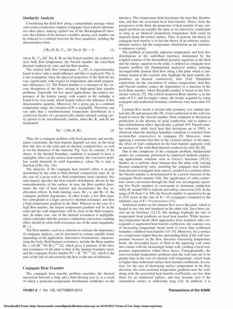
The experimental facility is the simplified model of a genericturbine internal cooling channel that is scaled up by a factor of 15.It consists of three pieces such as the inlet, test, and exit sectionsand each section has a cross-sectional dimension of 75� 75 mm,with longitudinal dimensions of 1400 mm, 1260 mm, 800 mm,respectively. The inlet and exit sections of the channel are madeof smooth flat walls, whereas one wall of the test section containsthe ribbed perturbation elements, Fig. 2.
Upstream of the channel, a honeycomb with 3 mm cell size isused along with a NACA bellmouth to provide flow conditioning.In gas turbine cooling passages, even though the aerodynamicflow development initiates in the root section of the turbine airfoil,the part of the cooling passage which promotes heat exchange isthe serpentine passages, modeled as the test section segment ofthe facility. Thus, the unheated aerodynamic development lengthin the inlet section provides further similarity with the real engineenvironment, Fig. 2. The flow downstream of the inlet duct isused as a reference point for calculating the Reynolds number,based on hydraulic diameter of the section and core flow velocitymeasured via Kiel-head probe. To better characterize the aerody-namic characteristics of the wind tunnel, dividing the square testsection inlet into 3348 grid points, hotwire anemometry dataare acquired at 100 kHz for one second duration at each point.
Journal of Heat Transfer OCTOBER 2013, Vol. 135 / 101001-3
Downloaded From: http://heattransfer.asmedigitalcollection.asme.org/ on 10/10/2013 Terms of Use: http://asme.org/terms
The resulting mean turbulence intensity is computed to be 5%,whereas toward the channel centerline drops to 2%.
The geometric similarity is of fundamental importance in tur-bine cooling passages due to its major influence on local flowstructures. In literature, there exist numerous alterations in param-eters such as aspect ratio, blockage factor, rib pitch to height ratio,rib angle of attack, rib shape and profile, and number of ribbedchannel walls. In this investigation, the square test section consistsof two flat glass lateral walls, and a glass top wall with an opticalaccess formed by a tensioned polyethylene film, at the base ofwhich lies the 25 mm thick one-piece slab with turbulators. Madeof a single AISI304 steel piece, it includes 6 square rib type per-turbators yielding a blockage ratio of 30%, rib pitch to height ratioof 10, and rib angle of attack of 90 deg, Fig. 2.
The chosen configuration results in a particularly complex flowbehavior with high levels of turbulence and a substantially three-dimensional flow character. From the perspective of aerodynamicsimilarity to engine conditions, experiments are conducted atReDh¼ 40,000. For conjugate heat transfer considerations, enginerepresentative Biot number and solid to fluid thermal conductivityratio are used, 1 and 600, respectively. At such a high thermalconductivity ratio and Biot number in the order of unity, consider-ing both thermal and convective resistances are of the same mag-nitude, the heat transfer dependence on thermal boundarycondition (conjugate case) is amplified. Alternatively, consideringthe criteria outlined in Ref. [7], using the characteristic lengthassociated with rib height, the local Brun number can be estimatedas 0.17; greater than 0.1, the conduction-convection couplingeffects are non-negligible.
The steel slab is painted black with uniform highly emissivelayers of Nextel Primer 5523 and Nextel Suede Coating 428-26,by means of an airbrush. The black coating is matte, soft, andbecause of diffuse reflection, the surface is nondazzling. At theexternal side, the slab is heated by means of a 25 lm thick Inconelsheet which is powered by a 16 V–150 A DC power supply. Thecurrent is dissipated as thermal energy by the Joule effect and is
conducted away by the parts in contact, Fig. 2. Inconel is knownto provide uniform heat flux across the applied area and retainsstrength over a wide range of temperatures. The external side ofthe steel slab is equipped with 100 mm thick thermal insulation;considering the conservation of energy, the heat flux losses intothe insulation can be estimated to be� 0.7%.
For calibration and monitoring purposes, the slab is instrumentedwith 15 T-type thermocouples, held in place by Omega OB-101thermally conductive, electrically insulating paste, applied to 3 mmholes drilled in the metallic slab at several locations along the chan-nel. The thermocouples are located 0.5 mm away from the surfaceof the slab, and considering the local Biot number in the order of10�3, the temperatures measured at the thermocouple bead loca-tions are equivalent to surface measurements.
The infrared measurements are conducted for the 4th pitch ofthe test section. In similar investigations, it has been demonstratedthat the flow appears periodic starting with the 3rd rib pitch [33].The Flir SC3000 infrared camera is located at 45 deg from the ver-tical; since the radiation exchange of surfaces are linearly propor-tional with the view factor, this configuration is selected toprovide a good compromise for pixels on both the vertical andhorizontal surfaces. The downstream face of the rib, along withthe rib-shadowed portion of the inter-rib space is observed via aNewport 75K00ER3 mirror, featuring a reflectance in the order of95% in the 8–9 lm range of the camera.
Experimental Methodology
The integrity of the infrared thermography measurements ishighly dependent on an accurate calibration of the camera objectsignal against the test surface temperature. Considering the largedifference in view factors of the direct and mirror reflected portionsof the image, independent in-situ calibrations are performed via theslab embedded thermocouples. Such regional calibration techniquesare based on the assumption that the slope of the calibration curveis constant for all the pixels, which enables the use of a single curve
Fig. 2 Schematic of the experimental setup
101001-4 / Vol. 135, OCTOBER 2013 Transactions of the ASME
Downloaded From: http://heattransfer.asmedigitalcollection.asme.org/ on 10/10/2013 Terms of Use: http://asme.org/terms

established at the reference. The local out of focus compensation,presenting itself as a bias shift among pixels, is corrected by a sin-gle image acquired at uniform ambient temperature.
The perspective distortions are corrected independently for eachregion of the sampled data by projection transformations, and aremapped onto a plane. The resolution of the transformed image issuperficially augmented in each dimension through sub-pixel inter-polation, resulting in a mean scale factor of 2.64 pixels/mm.
Furthermore, the acquired temperature results are ensured toreflect pitch to pitch temperature periodicity by linearly weightedaveraging of overlap regions among 4th and 5th pitches. Finally,in order to reduce the noise content, a median filtering methodol-ogy is used; this is typical for applications where the goal is tosimultaneously reduce peek noise and preserve edges. The tem-perature distribution across the channel is averaged with respectto the symmetry plane data followed by a Gaussian low pass filterto smooth out spuriously high gradients.
To acquire the surface heat flux distribution, a single genericpitch of the ribbed channel is modeled by COMSOL software.The boundary conditions for the numerical 3D conduction prob-lem are uniform heat flux, in this case 1733 W/m2, along the slabexternal surface, the measured temperature distribution on thewetted top surface, adiabatic lateral walls, and periodic boundarycondition on the transverse direction where the solid, in reality, isinterrupted, Fig. 3. The mesh consists of over 1.5� 106 tetrahedralelements with a maximum body and surface element size of 1 mmand 0.1 mm, respectively.
Enhancement Factor Calculation From the infrared thermog-raphy measured surface temperatures, and the surface heat fluxdistributions obtained from COMSOL, it is possible to calculatethe local heat transfer coefficient, h(x,y)¼ q(x,y)/(T(x,y)� T1),where T1 is the thermocouple measured air bulk temperaturealong the channel axis, experimentally verified to vary linearlyfrom inlet to exit and considered as constant within a pitch. Subse-quently, the computed heat transfer coefficient is nondimensional-ized as Nusselt number, Nu¼ h(x,y)Dh/kf, where Dh is the channelhydraulic diameter and kf is the thermal conductivity of air.
In order to quantitatively assess the impact of artificial rough-ness elements on internal cooling channel performance, and thusto determine the relative heat transfer enhancement, the Nusseltnumber is normalized with respect to an empirical heat transfercorrelation, EF¼Nu(x,y)/Nuo. The denominator is obtained fromthe Dittus-Boelter equation
Nuo ¼ 0:023Re4=5Dh Pr0:4 (3)
a correlation for computing the local Nusselt number for hydro-dynamically and thermally fully developed turbulent flows insmooth circular tubes, valid for 0.7<Pr< 160, ReDh> 104, andL/Dh> 10.
Uncertainty Analysis. In the scope of this study, the heat trans-fer measurements have three sources of uncertainty resulting fromindependent contributions of the wall temperature, the COMSOLcalculated surface heat flux and the free-stream air temperature. It
is estimated with a single sample uncertainty analysis based onthe method proposed by Kline and McClintock [34].
The overall uncertainty in wall temperature measurements canbe decomposed into several contributing factors, such as theuncertainty associated with the calibration of thermocouples, thevariation of object signal due to camera noise, the radiation emit-ted by the optical film medium, and the uncertainty introduced bythe infrared image data reduction, as well as filtering and calibra-tion curve fitting. The calibration of the T-type thermocouples isconducted in an oil bath by means of a thermometer with a resolu-tion of 0.1 K over a range of 15 points. Including the effects ofanalog to digital discretization error, the thermocouple uncertaintyis computed to be 0.18 K; the value is within the calibrationcurve’s mean deviation from linearity (�0.15 K). The infraredcamera object signal, a function of the spatial location and the sur-face temperature, varies on average by 3.2 intensity units among30 consecutive images. Considering the calibration curve slope, itresults in a camera noise associated temperature uncertainty of0.06 K. The temperature difference on the polyethylene opticalfilm during the calibration and the data acquisition is measured tobe up to 1 K; and through experimental observation, the resultingobject signal variation corresponds to 0.2 K slab temperature devi-ation. Another uncertainty contributor is the lateral temperaturenonuniformity at a given camera calibration instance; estimatedby the deviation of thermocouple readings in the lateral direction,its propagation to temperature-object signal relation is of the order0.1 K. The contribution of raw infrared image filtering procedureto uncertainty is around 0.15 K. Lastly, the uncertainty introducedby the calibration curve fitting procedure is quantified as the devi-ation of the points from the second order polynomial fit (up to0.12 K). Considering the above mentioned quantities, the cumula-tive infrared thermography wall temperature measurement accu-racy is estimated to be 60.35 K.
The heat flux at the wetted surface of the slab results from a nu-merical computation, where the boundary conditions consist ofmeasured wall temperature and imposed slab external side heat-flux. Suitable for experimental uncertainty propagation into nu-merical models, Ref. [35] considers a deterministic perturbationapproach to each of the physical independent quantities; the dif-ferences with the unperturbed solution provide an estimate on sen-sitivities. Perturbations in the external boundary heat-flux (proneto errors from voltage, current, and area measurements), alongwith uncertainty in infrared wall temperature, are observed topropagate and produce a cumulative surface heat flux uncertaintyof 0.76%.
The local free-stream air temperature, T1, is computed fromthe thermocouples located at the inlet/exit cross sections of the fa-cility. With additional sources of uncertainty provided by thedeviation of the three readings among one another, the resultingcumulative air temperature uncertainty is 0.55 K.
Given the above calculated individual contributors, the cumula-tive expected uncertainty in heat transfer coefficient is estimatedto be 3.4%. With the additions of air thermal conductivity and hy-draulic diameter uncertainties, this translates into a Nusselt num-ber uncertainty of 3.7%. Moreover, with the Reynolds numberuncertainty of order 63.3%, the subsequent enhancement factoraccuracy is around 64.5%.
Fig. 3 Ribbed slab FEM model
Journal of Heat Transfer OCTOBER 2013, Vol. 135 / 101001-5
Downloaded From: http://heattransfer.asmedigitalcollection.asme.org/ on 10/10/2013 Terms of Use: http://asme.org/terms

Methodology Validation. In order to verify the experimentalconjugate heat transfer measurement technique, as well as for con-ducting baseline investigations, an initial experiment is conductedon a flat plate geometry where uniform heat flux boundary condi-tion is applied at the external side of the channel bottom wall. Thewetted surface temperature distributions are acquired via infraredthermography; and, along with COMSOL acquired top surfaceheat flux, the heat transfer coefficient can be computed. The corre-sponding symmetry line average Nusselt number is 95.8, in goodagreement with the circular tube Dittus-Boelter correlation whichprovides 96.4, Eq. (3).
For parallel turbulent flow over a fully turbulent, no pressuregradient flat plate, with fixed aero and thermal boundary layershapes, the corresponding iso-heatflux and iso-thermal interfaceboundary condition Nusselt number correlations are [36]
Nux0 ¼ 0:0308Re4=5x0 Pr1=3 (4)
and
Nux0 ¼ 0:0296Re4=5x0 Pr1=3 (5)
In the test case, the flow starts developing further upstream ofthe heated section, i.e., the aerodynamic boundary layer startsdeveloping prior to its thermal counter-part. Its effect on local Nus-selt number is rectified by an unheated entry length correction [36]
Nux0n ¼ Nux0= 1� n=x0ð Þ9=10� �1=9
(6)
where n is the unheated inlet section length and x0 is the longitudi-nal dimension calculated locally from the inlet. Utilizing Eqs. (4)and (5) and by correcting for the unheated aerodynamic inletlength in Eq. (6), it is possible to acquire baseline Nusselt numberdistributions for purely convective heat transfer cases.
Figure 4 presents the experimental laterally averaged conjugateNusselt number distribution with error bars, along with the theo-retical cases where the interface boundary condition is iso-heat-flux and isothermal. The longitudinal dimension is expressed asthe local Reynolds number, with length scale (x) referenced to theheated slab leading edge. In all three cases, due to thermal bound-ary layer development, there is a monotonous decrease in Nusseltnumber at increased axial position.
In agreement with theory [8], the isothermal boundary condi-tion case is a lower bound on heat transfer since, as the thermalboundary layer develops, the descended layers of fluid at theadjoining wall come into contact with closer solid temperatures,decreased temperature head, resulting in reduced heat flux. Asless work is done on the local thermal boundary layer, the cross-sectional temperature gradients near the wall reduce in the down-stream direction, yielding lower heat transfer. In contrast, for theiso-heatflux wetted boundary condition, an equal amount of work
is inflicted on the thermal boundary layer, independent of localheat transfer coefficient.
In the conjugate case, in addition to the adverse effects of ther-mal boundary layer development on Nusselt number, the conduc-tion within the solid has also an impact on local heat transfer. Onone hand, the longitudinal conduction within the solid in the flowupstream direction (in this case characterized to be in the order of2.5% of the bottom imposed value) ensures more than isothermallocal heat flux. But, on the other hand, since the solid cannot sus-tain as large thermal gradients as the iso-heatflux boundary condi-tion, the resultant conjugate heat transfer coefficient is less. Asdemonstrated in Fig. 4, within the uncertainty, the experimentalconjugate results are in between the two limiting cases. Overall,the Nusselt number has low dependency on thermal boundarycondition, of the order 3%; this is expected considering the turbu-lent flat plate flow at relatively high Reynolds number [14].
Results
Rib Roughened Channel Mean Flow Field. As an overview,the mean flow field inside the rib-roughened cooling passage ispresented by the complimentary PIV investigation, Fig. 5 [33].
Starting from an unperturbed state, as the fluid encounters therib, it experiences a strong deviation imposed by the obstacle,forcing it to adapt to the decreased channel cross section. It isaccelerated in order to pass the rib and subsequently experiencesan expansion further downstream, as the cross sectional areaabruptly increases following the backward face of the rib. Theperiodic behavior of the consecutive acceleration in the vicinity ofthe obstacle and the deceleration of the fluid in the inter-rib spac-ing is one of the most dominant aspects of the flow in rib-roughened channels. At the investigated Reynolds number, since
Fig. 4 Conjugate flat plate Nusselt number Fig. 5 Visualization of the ribbed channel flow field [33]
101001-6 / Vol. 135, OCTOBER 2013 Transactions of the ASME
Downloaded From: http://heattransfer.asmedigitalcollection.asme.org/ on 10/10/2013 Terms of Use: http://asme.org/terms

the contribution of the inertial terms into fluid momentum balanceis dominating, the flow is not able to follow the abrupt changes ofthe surface. It is the sudden enlargement of the channel down-stream of the perturbator which causes the stream to separate fromthe surface, resulting in the recirculation region downstream,Fig. 5.
Apart from this recirculation region, the flow field exhibits aclockwise rotating separated flow region on top of the rib, V2, aswell as a small vortex cell V1 in the downstream corner of the rib.Located within the rib wake, the V1 vortex exhibits a counter-clockwise rotary motion, opposing the mean angular velocity ofthe recirculation region. Toward the obstacle, the stream traces ofV1 and recirculation region coincide, such that the flow impingesonto the downstream surface of the rib. Similarly to V2, the V1
vortex cell occurs over the entire channel span.Further downstream, the mean flow passes the rib and the sub-
sequent recirculation zone, and at the reattachment region, thereexists an impingement towards the channel bottom wall. In thiscase, defined by the change of sign in skin friction coefficient, thereattachment point is determined to be around x/H �5.5 down-stream of the rib center-plane. Once the flow reattaches, theboundary layer redevelops and grows within the inter-rib spacing,until the next turbulator. Immediately upstream of the rib, thestream strongly impinges on the vertical surface such that its vor-ticity and the repeatedly induced separation of the boundary layergive rise to the clockwise rotating vortex structure V3 [33]. Thiseffect is observed to be most dominant towards the symmetryplane. At the channel bottom wall, as the mean flow approachesthe rib, a widthwise deflection occurs, indicated by the abrupttransverse flow motion. This pressure driven acceleration inducesa region of high horizontal momentum, which is eventually cap-tured by the mainstream flow and shed away downstream. As theflow crosses over to the next rib pitch, the described cyclic behav-ior of complex flow interactions perpetuates.
Local Temperature and Heat Flux Distributions. The IRmeasured projected surface temperature and its cross-sectionalsymmetry line distribution are presented in Figs. 6 and 7, whereall dimensions are normalized by the rib height, H. Overall, it isevident that the lowest temperatures are measured in the vicinityof the rib. On the rib upstream facing wall, �1.5< x/H<�0.5,there is a continuous decrease in temperature, followed by a rela-tively isothermal region on the rib top surface |x/H|< 0.5, Fig. 6.On the rib downstream face, 0.5< x/H< 1.5, the temperaturesmonotonously increase, and this trend continues in the beginningof the inter-rib space until x/H¼ 2.2, where the highest wall tem-peratures are observed, Fig. 7. Over the remaining inter-rib space,the temperature decreases monotonously in the streamwise direc-tion, x/H from 2.2 to 6 and from �6 to �1.5. In the widthwisedirection, toward the lateral walls, there exists a gradual decreasein temperature with respect to the symmetry plane, more signifi-cant in the |y/H|> 1.3 region.
By applying this temperature distribution as a boundary condi-tion to COMSOL, it is possible to extract the local surface-normalheat flux. Figure 7 presents the symmetry line heat flux distribution,
normalized by the uniform value imposed under the slab. The fluxredistribution within the solid is evident, where on top of the rib upto 120% and in the downstream region as low as 10% of the bottomflux values are observed. Even though the global trend of lowertemperatures implying higher surface heat extraction is valid, invarious regions of the wetted surface, these effects are amplified orsuppressed depending on local conduction.
In the rib upstream region, �3.5< x/H<�1.5, it is possible toobserve an almost uniform decrease in heat flux, where the tem-perature presents an initial plateau followed by a steep decrease,just upstream the rib edge. Similarly on the upstream face of therib, �1.5< x/H<�0.5, where the temperature presents a monoto-nous decrease, the heat flux is shown to reflect a sinusoidal behav-ior. On the rib top surface, toward the center, a heat flux peak isobserved, otherwise not noted in the temperature contours. Simi-larly, even though the hottest spot in the temperature contoursoccurs at about x/H¼ 2.2, the minimum heat flux occurs at x/H¼ 1.9. These types of flux redistribution behavior are an artifactof the solid conduction, observed to be especially dominant in thevicinity of the rib which creates a local heat sink effect, Fig. 7.Overall, the temperature and flux distributions reflect a locallydecoupled behavior, where the isothermal or iso-heat flux convec-tive boundary condition cases would assume otherwise.
In conjugate heat transfer applications, a more global quantitywhich characterizes the effects caused by the existence of a nonin-sulating solid is the longitudinal heat flux, which quantifies theglobal axial conduction. For the present configuration, at all cross-sections within the inter-rib space which are at least 1.5 H awayfrom the rib, the ratio between the longitudinal heat flux and theimposed external side heat flux is in the order of �8%; with themaximum being �17% located toward the channel symmetry-lineclose to the wetted surface.
Heat Transfer Distributions and Aero-ThermalInteractions. Considering the characteristic flow patterns devel-oping inside internal ribbed cooling channel geometries, the localheat transfer can be contrasted with the nearby flow structures.Figure 8 presents the local EF distribution, in addition to time-averaged PIV stream traces on the bottom wall, along with the
Fig. 6 Pitch temperature distribution (K)
Fig. 7 Symmetry line temperature/normalized heat flux
Journal of Heat Transfer OCTOBER 2013, Vol. 135 / 101001-7
Downloaded From: http://heattransfer.asmedigitalcollection.asme.org/ on 10/10/2013 Terms of Use: http://asme.org/terms

symmetry plane V3, V2, and V1 vortex structures located in frontof, over, and behind the rib, respectively [33]. Moreover, thewidthwise averaged EF chart can be found in Fig. 9.
The �6< x/H<�3.8 region is the part of the ribbed channelwhere the flow is attached immediately downstream of the largeseparation region. Slight stream-wise decrease in enhancementfactor is associated with the thermal boundary layer growth. Onaverage, the significantly greater than flat plate EFs, EF� 2.4� 1,is caused by the high levels of turbulence. Further downstream, forthe region bounded by �3.8< x/H<�2.5, the evident axialdecrease in EF seems to be associated with the potential effect ofthe rib reducing the longitudinal component of the velocity, caus-ing an adverse effect on the boundary layer growth. In the immedi-ate vicinity of the rib, �2.5< x/H<�1.5, the flow is dominatedby the existence of the clockwise rotating corner vortex V3.Because of the blockage, the cold mainstream fluid is deviatedaway from the bottom wall which prevents its contact with theheated surface, resulting in further reduced EFs, of the order 1.55.
In Fig. 8, the upstream face of the rib consists of the �1.5< x/H<�0.5 region. Within the �1.5< x/H<�0.8 domain, locallylower enhancement factors, EF� 1.2–1.6, are associated with theregional insulation created by the V3 flow structure. Around x/H¼�0.8, a local peak in heat transfer is observed, EF� 2.6, aconsequence of V3 vortex downwash along with the mainstreamflow impingement, consistent with the PIV data [33]. To a lesserextent, this vortex downwash can also be observed on the bottomwall, indicated by the local peak in EF at �1.8< x/H<�1.5,Fig. 9. Toward the lateral wall, �3.5< x/H<�0.5 |y/H|> 1.3, theflow field is subjected to pressure driven lateral acceleration of therib impinging mainstream flow, where this high momentum regiontranslates to locally augmented EFs, Fig. 8.
The top face of the rib, |x/H|< 0.5, is where the highest EFs areobserved. This is caused by the reduction in effective flow area, inturn resulting in much higher momentum flow, generating aregion of high heat transfer. In Fig. 9, the location of EF peak(�3.6) at x/H¼ 0.15, is consistent with the aerodynamic throatand the V2 vortex.
The backward face of the rib, 0.5< x/H< 1.5, along with theimmediate downstream area in the longitudinal direction, 1.5< x/H< 2, are the regions where the lowest EF values are observed,Fig. 8. This is caused by the large separation behind the rib, gener-ating a local low momentum region with reversed flow, where theheat transfer is considerably less than in the rest of the passage.This is clearly observed by the sudden drop in EF for 0.5< x/H< 0.9, Fig. 9. In addition to the global separation, evidenced bythe pitch minimum EFs of the order �0.5, the V1 vortex furtherisolates the solid from the mainstream flow, observed both on therib vertical and downstream walls, 0.9< x/H< 1.5 and 1.5< x/H< 2. The local peaks at x/H¼ 1.2 and x/H¼ 1.6 are caused bythe impinging V1 vortex downwash, although slightly, locally aug-menting EF, Fig. 9.
Further away from the rib, 2< x/H< 6, the flow field is associ-ated with the downstream recirculation bubble until the reattach-ment zone. Due to the increased penetration of the coolmainstream flow at increased axial position, the EF augments inthe streamwise direction, Fig. 9.
Reattachment and Enhancement Factor. In Fig. 9, at aroundx/H� 3.4, prior to the aerodynamic reattachment point occurringat xR/H� 5.5 [33], an unexpected peak in EF exists. Constitutingonly a local maximum, the reattachment associated global maxi-mum occurs further downstream at x/H� 6.01. These findings areconsistent with Ref. [28], since the recirculation bubble size is inbetween the criteria for long or short bubbles where the peak heattransfer is predominantly observed upstream and downstream ofthe reattachment point. The double peak reattachment heat trans-fer has already been observed in Refs. [27,31].
In Fig. 8, the reattachment region is estimated by the gray linesdrawn in between 5< x/H< 6.1. The earlier line presents the localmaximum in longitudinal derivative of enhancement factor. Astrong positive gradient in EF, at a region bordering the large sep-aration bubble, is indicative of the initialization of flow reattach-ment. If a reattachment point is to be selected, this would be thelower limit of the reattachment region. The gray line furtherdownstream indicates the location of the longitudinal maximumin EF. For this geometry, since the rib downstream separationbubble is relatively narrow, and the global peak in heat transferoccurs after the reattachment point [28,32], thus the latter line issuggested to be an upper bound on the reattachment. Furthermore,analyzing the shape in the lateral direction, Fig. 8, it is observedthat the re-attachment is earlier on the channel symmetry line. To-ward the lateral walls, the location of the reattachment region ini-tially increases until y/H¼ 0.8, followed by a decrease inreattachment length at the very edge of the channel, consistentwith prior literature [27].
Role of Conduction in Convective Heat Transfer. Contrastingthe findings of this conjugate investigation to analogous convec-tive measurements with iso-heatflux wetted surface boundary con-dition [37], Table 1 presents the area averaged EFs for thedifferent portions of the ribbed channel. In addition, quantifying
Fig. 8 Pitch enhancement factor distribution
Fig. 9 Widthwise averaged EF and X distribution
101001-8 / Vol. 135, OCTOBER 2013 Transactions of the ASME
Downloaded From: http://heattransfer.asmedigitalcollection.asme.org/ on 10/10/2013 Terms of Use: http://asme.org/terms
the nonuniformity with respect to the pitch mean value, percentstandard deviations is computed. Furthermore, for the symmetryplane, reattachment associated maximum heat transfer locations,xmax, are also presented. Finally, to contrast the effect of a changein surface boundary condition, the conjugate EF deviation fromthe iso-heatflux case, X¼ 1�EFconj/EFconv, is charted in Fig. 9,while the regionally averaged values are presented in Table 1.
In the conjugate case, the average EF on the upstream face is rel-atively high, 2.34, due the impingement of the mainstream flow onthe surface. On the top face, the EF is even further augmented to2.99, due to the local increase of momentum by the decrease ineffective area. On the downstream face of the rib, the lowest aver-age EF is observed, 0.86, caused by the large separation bubblebehind the step. The rib, inter-rib, and pitch averaged EFs are 2.07,2.01, and 2.02, respectively. Comparing the findings with the iso-heatflux surface boundary condition investigation, the variations inarea averaged heat transfer coefficients are apparent, Table 1. Thiseffect is specifically emphasized in the vicinity of the rib, |x/H|< 3,evidenced by the large deviation in EF from the iso-heatflux case,Fig. 9. This is believed to be attributed to the dominant conductioncoupling, particularly observed around the rib as a result of closelydistributed local heat sinks and sources. Particularly, with respect tothe iso-heatflux investigation, the high solid thermal gradient yieldsto large differences in boundary layer thermal history.
More specifically, in the inter-rib space close to the rib, �3< x/H<�1.5, the effect of conjugate boundary condition in EF canbe as large as 22%, Fig. 9. On the rib upstream face, �1.5< x/H<�0.5, the average deviation is 27%, and locally can be up to41% at x/H¼�1.4, where the V3 vortex is dominant. The vortexcreates an isolated region where the flow impinges on the side ofthe rib x/H��0.8, being heated up, moves toward the bottomwall with reversed flow. Due to the increase in bulk flow tempera-ture, and local decrease in wall temperature, Fig. 7, the tempera-ture head reduces in the flow direction. Consistent with thefundamental conjugate heat transfer theory [14], a decrease intemperature head in the flow direction results in lower than con-vective EFs, further augmenting X at x/H¼�1.4.
Over the rib top surface, the effect of the thermal boundary con-dition seems to have diminished to 5% globally, Table 1. Withinthis region, due to the aerodynamic throat, the local momentum isgreatly augmented which results in high heat transfer coefficients,but as a consequence the dependency on thermal boundary condi-tion is relatively low [14]. Additionally, in the presence of con-duction within the rib, the top surface is a heat sink, as it issurrounded by much lower EF regions. This effect may explainthe slightly higher conjugate EFs observed toward the rib center-line with respect to the iso-heatflux case, Fig. 9.
Downstream of the rib, 0.5< x/H< 3, the convective case over-estimates the EF in the order of 55% and 70% on the rib down-stream face and on the near bottom wall, respectively. Such largevalues are consistent for regions of lower momentum anddecreased turbulence levels, where the thermal boundary condi-tion selection has a much more dominant effect on heat transfer[14]. In Fig. 7, this is the portion of the pitch where only �20% ofthe bottom heat flux reaches the surface, resulting in much lowerlocal thermal gradients than the iso-heatflux case, and thusreduced conjugate heat transfer.
Further downstream, for the conjugate boundary condition mea-surement, it has been observed that the peak heat transfer occursat x/H¼ 6.01, roughly 0.5 H downstream of the convective case.These findings are consistent with literature indicating anupstream shift in peak reattachment Nusselt number location withdecreased thermal conductivity ratio, at the limit being purelyconvective [31].
Considering the global trends in Fig. 9, for a low conjugate EFregion, the local work input to the flow is higher for the convec-tive case since equal amounts of heat flux are imposed on theboundary layer independently of the local heat transfer coefficient.This could imply that under these circumstances the surfaceboundary layer will have a stronger gradient in the convectivecase than in the conjugate case, creating higher convective EFregions as seen in 0.5< |x/H|< 3, Fig. 9. On the contrary, for aregion of high conjugate EF, the heat flux input to the fluid ishigher than the iso-heatflux case. With a similar argument, it ispossible to deduce that these regions will have lower convectiveEF values, e.g., rib top, in agreement with Ref. [8]. Consequently,a more nonuniform conjugate heat transfer distribution is main-tained across the domain, where the percent EF standard deviationis 36% in contrast to the convective case which is 20%, Table 1.
Furthermore, comparing the pitch averaged EFs, the case studywith iso-heatflux boundary condition results in a mean EF of 2.31,an over-prediction of the global heat transfer by 14%. To providea sense of scale to the repercussions associated with such an error,the findings can be extrapolated to the real engine environment byassuming a self-similar internal turbine cooling channel where thecompressor air coolant temperature is 900 K and the blade temper-ature is at the material limit, which is around 1200 K. Consideringidentical heat fluxes for both convective and conjugate boundarycondition cases, if the interface boundary condition is set to iso-heatflux, which is unrealistic, then the predicted blade temperaturereduces to 1163 K. Although miscalculation of blade bulk temper-ature by 37 K, may seem like a relatively small error, underesti-mations of metal temperature, as little as 30 K, are reported toreduce the life cycle of blades by half [38]. In turbine applications,when the blade temperature exceeds detrimental limits, thermalstresses become excessive and affect the structural integrity; bladelife decreases, possibly resulting in thermal failure. Therefore, itis critical to predict accurately the local heat transfer coefficient aswell as the local blade temperature to prevent local hot spots andincrease turbine blade life. Alternatively, by models accountingfor the conjugate nature of the heat transfer interaction, the enginedesigners may choose to decrease the safety factor and maintainthe same blade temperatures. This would reduce the required cool-ant flow, and thus improve on the turbine efficiency, resulting inlower fuel costs for the same power output.
Conclusion
By infrared thermography surface temperature measurements,and via finite element energy balance within the solid, an experi-mental conjugate heat transfer investigation is conducted for a rib-roughened internal cooling channel geometry. The enhancementfactor trends are compared with the basic flow features. For theattached flow immediately downstream of the large separation
Table 1 Comparison with convective heat transfer
Region averaged EFs
Rib
Boundary condition Ups. Top Downs. Mean Inter rib Pitch ave. % Stand. Dev. xmax
Conjugate 2.34 2.99 0.86 2.07 2.01 2.02 36% 6.01IsoHeatFlux 3.20 2.86 1.89 2.65 2.20 2.31 20% 5.45X Deviation 27% �5% 55% 26% 10% 14% — —
Journal of Heat Transfer OCTOBER 2013, Vol. 135 / 101001-9
Downloaded From: http://heattransfer.asmedigitalcollection.asme.org/ on 10/10/2013 Terms of Use: http://asme.org/terms

region, associated with the boundary layer growth, a slight overalldecrease in enhancement factor is observed. In the immediate vicin-ity of the rib upstream face, the aero-thermal distribution is domi-nated by the existence of the clockwise rotating corner vortex V3.The top face of the rib is where the overall highest EFs, and lowesttemperatures, are observed, an artifact of reduction is effectivearea. The rib downstream region, until reattachment, is where thelowest EF values are observed, caused by the large time-averagedseparation bubble in the wake of the rib. In the reattachment zone,a double peak in enhancement factor is reported, consistent withthe size of the recirculation bubble. The initial smaller peak islocated prior to and the second global maximum in enhancementfactor is observed after the reattachment point.
More globally, the heat flux redistribution within the solid isdemonstrated, locally in the order of 20% surplus on top of the riband 90% deficit on the rib downstream bottom wall. Even thoughthe global trend of lower temperatures implying higher surface heatextraction is observed to be valid, in various regions of the wettedsurface, these effects are amplified or suppressed depending onlocal conduction, especially visible around the rib. Moreover, onthe inter-rib spacing, the axial conduction is computed to be as high17%. When compared with the convective iso-heatflux boundarycondition findings, the effects of imposing the conjugate boundarycondition result in mean deviations of 26%, 10%, and 14% over therib, inter-rib space, and on the entirety of the pitch. Locally, thiseffect can be enhanced up to 70% in the rib downstream separationregion. Moreover, when the surface boundary condition is switchedfrom convective to conjugate, a half rib height downstream shift ofreattachment associated peak heat transfer is observed.
In conclusion, the findings clearly indicate that accounting forthe true thermal history of the flow, and in turn modeling the solidconduction in such high gradient convective heat transfer surfacesis crucial. In the specific case of the turbine cooling application,switching the thermal boundary condition from conjugate to iso-heat-flux resulted in a projected blade surface temperature reduc-tion of 37 K in the engine environment. The underestimation ofblade bulk metal temperature by 30 K is reported to reduce the lifecycle of blades by half. For unbiased results, studies of such appli-cations should respect the correct similarity parameters, i.e. repro-ducing the correct thermal boundary conditions.
Acknowledgment
The authors acknowledge the financial support of the Air ForceOffice of Scientific Research (AFOSR), Grant No. FA8655-08-1-3048, supervised by Dr. S. Surampudi and Dr. G. Abate of the Eu-ropean Office of Aerospace Research and Development.
Nomenclature
Bi ¼ h d/ks (Biot number)d ¼ slab thickness
Dh ¼ channel hydraulic diameterEc ¼ Eckert numberEF ¼ Nu/Nuo (enhancement factor)
h ¼ q/DT (heat transfer coefficient)H ¼ rib heightk ¼ thermal conductivityK ¼ ks/kf
Nu ¼ h Dh/kf (Nusselt Number)Nuo ¼ 0.023ReDh
4/5Pr0.4 (Dittus Boelter corr.)PIV ¼ particle image velocimetry
Pr ¼ Prandtl numberReDh ¼ qVDh/l (Reynolds number)
T ¼ temperatureDT ¼ Twall�T1 (temperature head)TC ¼ thermocouple
x ¼ longitudinal distance (reference from rib center-plane orheated slab leading edge)
x0 ¼ longitudinal distance from inlet
xR ¼ reattachment distancexmax ¼ maximum Nusselt number location
X ¼ 1�EFconj/EFconv
y ¼ lateral distance
Subscripts
conj ¼ conjugate boundary conditionconv ¼ convective boundary condition
f ¼ fluids ¼ solid1¼ free-stream
References[1] Kay, J. M., and Nedderman, R. M., 1985, Fluid Mechanics and Transfer Proc-
esses, Cambridge University Press, Cambridge, UK.[2] Luikov, A. V., 1974, “Conjugate Convective Heat Transfer Problems,” Int. J.
Heat Mass Transfer, 17(2), pp. 257–265.[3] Cole, K. D., 1997, “Conjugate Heat Transfer From a Small Heated Strip,” Int.
J. Heat Mass Transfer, 40(11), pp. 2709–2719.[4] Perelman, L. T., 1961, “On Conjugated Problems of Heat Transfer,” Int. J. Heat
Mass Transfer, 3(4), pp. 293–303.[5] Luikov, A. V., and Aleksachenko, V. A., 1971, “Analytical Methods of Solu-
tion of Conjugated Problems in Convective Heat Transfer,” Int. J. Heat MassTransfer, 14(8), pp. 1047–1056.
[6] Pozzi, A., Quaranta, G., and Tognaccini, R., 2008, “A Self-Similar Unsteady FlowWith Conjugated Heat Transfer,” Int. J. Heat Mass Transfer, 51(7–8), pp.1804–1809.
[7] Mosaad, M., 1999, “Laminar Forced Convection Conjugate Heat Transfer Overa Flat Plate,” Int. J. Heat Mass Transfer, 35(5), pp. 371–375.
[8] Mori, S., Sakakibara, M., and Tanimoto, A., 1974, “Steady Heat Transfer toLaminar Flow in a Circular Tube With Conduction in the Tube Wall,” HeatTransfer-Jpn. Res., 3(2), pp. 37–46.
[9] Barozzi, G. S., and Pagliarini, G., 1985, “A Method to Solve Conjugate HeatTransfer problems: the Case of Fully Developed Laminar Flow in a Pipe,”ASME J. Heat Transfer, 107(1), pp. 77–83.
[10] Li, Y., and Ortega, A., 1998, “Forced Convection From a Rectangular Heat Sourcein Uniform Shear Flow: The Conjugate Peclet Number in the Thin Plate Limit,”Intersociety Conference on Thermal Phenomena, May, Seattle, WA.
[11] Ortega, A., and Ramanathan, S., 2003, “On the Use of Point Source Solutionsfor Forced Air Cooling of Electronic Components—Part II: Conjugate ForcedConvection From a Discrete Rectangular Source on a Thin Conducting Plate,”ASME J. Electron. Packag., 125(2), pp. 235–243.
[12] Dorfman, A., 1982, Heat Transfer for Flow Past Non-Isothermal Bodies, Izd.Mashinostroenie, Moscow.
[13] Dorfman, A., 1985, “A New Type of Boundary Condition in Convective HeatTransfer Problems,” Int. J. Heat Mass Transfer, 28(6), pp. 1197–1203.
[14] Dorfman, A., 2009, Conjugate Problems in Convective Heat Transfer, Taylor& Francis, London.
[15] Dorfman, A., 1971, “Exact Solution of Thermal Boundary Layer Equation WithArbitrary Temperature Distribution on Streamlined Surface,” High Temp., 8(5),pp. 955–963.
[16] Young, T. J., and Vafai, K., 1998, “Convective Cooling of a Heated Obstacle ina Channel,” Int. J. Heat Mass Transfer, 41(20), pp. 3131–3148.
[17] Kanna, P. R., and Das, M. K., 2006, “Conjugate Heat Transfer Study ofBackward-Facing Step Flow—A Benchmark Problem,” Int. J. Heat MassTransfer, 49(21–22), pp. 3929–3941.
[18] Simpson, R. L., 1983, “A Model for the Backflow Mean Velocity Profile,”AIAA J., 21(1), pp. 142–143.
[19] Westphal, R. V., Eaton, J. K., and Johnston, J. P., 1981, “A New Probe for Mea-surement of Velocity and Wall Shear Stress in Unsteady, Reversing Flow,”ASME J. Fluids Eng., 102(2), pp. 478–482.
[20] Vogel, J. C., and Eaton, J. K., 1985, “Combined Heat Transfer and FluidDynamic Measurements Downstream of a Backward-Facing Step,” ASME J.Heat Transfer, 107, pp. 922–929.
[21] Zukauskas, V. A., and Pedisius, K. A., 1987, “Heat Transfer to Reattached FluidFlow Downstream of a Fence,” Warme- und Stoffubertagung, 21(2–3), pp. 125–131.
[22] Eaton, J. K., and Johnston, J. P., 1981, “A Review of Research on SubsonicTurbulent Flow Reattachment,” AIAA J., 19(9), pp. 1093–1100.
[23] Eaton, J. K., Johnston, J. P., and Jeans, A. H., 1979, “Measurements in Reat-taching Turbulent Shear Layer,” Proceedings 2nd Symposium on TurbulentShear Flows, London.
[24] Armaly, B. F., Durst, F., and Pereira, J. C. F., 1983, “Experimental and TheoreticalInvestigation of Backward-Facing Step Flow,” J. Fluid Mech., 127, pp. 473–496.
[25] Adams, E. W., and Johnston, J. P., 1988, “Effects of Separating Shear Layer onthe Reattachment Flow Structure Part 2: Reattachment Length and Wall ShearStress,” Exp. Fluids, 6, pp. 493–499.
[26] Avancha, R. V. R., and Pletcher, R. H., 2002, “Large Eddy Simulation of theTurbulent Flow Past a Backward-Facing Step With Heat Transfer and PropertyVariations,” Int. J. Heat Fluid Flow, 23, pp. 601–614.
[27] Armaly, B. F., Durst, F., and Kottke, V., 1981, “Momentum, Heat, and MassTransfer in Backward-Facing Step Flows,” Proceedings of 3rd Symposium onTurbulent Shear Flows, Davis, CA.
101001-10 / Vol. 135, OCTOBER 2013 Transactions of the ASME
Downloaded From: http://heattransfer.asmedigitalcollection.asme.org/ on 10/10/2013 Terms of Use: http://asme.org/terms

[28] Sparrow, E. M., Kang, S. S., and Chuck, W., 1987, “Relation Between thePoints of Flow Reattachment and Maximum Heat Transfer for Regions of FlowSeparation,” Int. J. Heat Mass Transfer, 30(7), pp. 1237–1246.
[29] Aung, W., 1983, “An Experimental Study on Laminar Heat Transfer Down-stream of Backsteps,” ASME J. Heat Transfer, 105(4), pp. 823–829.
[30] Seban, R. A., Emery, A., and Levy, A., 1959, “Heat Transfer to Separated andReattached Subsonic Turbulent Flows Obtained Downstream of a SurfaceStep,” J. Aerosp. Sci., 28, pp. 809–814.
[31] Kanna, P. R., and Das, M. K., 2007, “Conjugate Heat Transfer Study of a Two-Dimensional Laminar Incompressible Wall Jet Over a Backward-Facing Step,”ASME J. Heat Transfer, 129(2), pp. 220–229.
[32] Jourdain, C., Escriva, X., and Giovannini, A., 1997, “Unsteady Fow Eventsand Mechanisms Leading to Heat Transfer Enhancement in a RibbedChannel,” Proceedings Eurotherm Seminar 55: Heat Transfer in Single PhaseFlow.
[33] Casarsa, L., and Arts, T., 2005, “Experimental Investigation of the AerothermalPerformance of a High Blockage Rib-Roughened Cooling Channel,” ASMEJ. Turbomach., 127(3), pp. 580–588.
[34] Kline, S. J., and McClintock, F. A., 1953, “Describing Uncertainties in Single-Sample Experiments,” J. Mech. Eng., 75, pp. 3–8.
[35] Rabin, Y., 2003, “A General Model for the Propagation of Uncertainty in Meas-urements Into Heat Transfer Simulations and Its Application to Cryosurgery,”Cryobiology, 46, pp. 109–120.
[36] Kays, W. M., Crawford, M. E., and Weigand, B., 2005, Convective Heat andMass Transfer, McGraw-Hill, New York.
[37] Cukurel, B., Selcan, C., and Arts, T., 2012, “Film Cooling Extraction Effects onthe Aero-thermal Characteristics of Rib Roughened Cooling Channel Flow,”ASME GT2012-68680.
[38] Han, J. C., 2006, “Turbine Blade Cooling Studies at Texas A&M University:1980–2004,” J. Thermophys. Heat Transfer, 20(2), pp. 161–187.
Journal of Heat Transfer OCTOBER 2013, Vol. 135 / 101001-11
Downloaded From: http://heattransfer.asmedigitalcollection.asme.org/ on 10/10/2013 Terms of Use: http://asme.org/terms


![Wetted Mobile Packed Bed [Compatibility Mode]](https://static.fdocuments.us/doc/165x107/577c77921a28abe0548ca292/wetted-mobile-packed-bed-compatibility-mode.jpg)


