Local Area Networks - EECS Instructional Support Group ...ee233/sp06/lectures/EE233_LAN.pdf · •...
29
Elaine_06_I-1 Local Area Networks Guest Instructor Elaine Wong
Transcript of Local Area Networks - EECS Instructional Support Group ...ee233/sp06/lectures/EE233_LAN.pdf · •...
Elaine_06_I-1
Local Area Networks
Guest InstructorElaine Wong

Elaine_06_I-2
Outline
• Introduction to Local Area Networks (LANs)• Network architecture • Geographical area• LAN applications
• LAN Technologies
• Ethernet• Fiber Distributed Data Interface (FDDI)

Elaine_06_I-3
System Architectures
Long Haul & Regional Networks
Metropolitan AreaNetworks (MANs)
Access Networks
• LANs are privately owned to carry internal data traffic within organisation
• Coverage area < 10 km
Local area networks
(LANs)

Elaine_06_I-4
Low-speed LANs,each existingwithin a building
High-speed Backbone LAN
Interconnection of LANs
storagearea network
• LANs may exist on many levels categorized by speed and application
Elaine_06_I-5
Ethernet

Elaine_06_I-6
Overview• Ethernet is the most popular LAN technology
- large installed base (500 million Ethernet nodes)- more than 95% of LAN traffic is Ethernet based
• Ethernet supports 10 Mb/s, 100 Mb/s (Fast Ethernet), 1 Gb/s(Gigabit Ethernet) and 10 Gb/s (10GbE)
• Ethernet standardized by IEEE (802.3 standard series)
• Widespread popularity- Specifications and rights to build and install Ethernet made
easily available to everyone- Design goals: create a simple network topology with efficient
shared resources, easy to configure and maintain, compatible across many manufacturers and systems
- Ethernet is competitively priced

Elaine_06_I-7
Invention of Ethernet• Invented in 1976 by Dr. Robert M. Metcalfe at the Xerox Palo
Alto Research Center
• Asked to build a networking system for computers “office of the future”
• First demonstration of Ethernet (2.94 Mb/s data rate)

Elaine_06_I-8
Standardization of Ethernet• In 1983, IEEE released first Ethernet standard (10 Mb/s) based
on 50 Ω thick coaxial cable in bus topology• In 1990, major advancement with unshielded twisted pair (UTP)
copper transmission medium (IEEE 802.3 10BASE-T)• Only point-to-point connections allowed in 10BASE-T• Repeater regenerates data received from one cable and
retransmit signal at all output cables to all users
Transmit
Receive Transmit
Receive10 Mb/s repeater
10 Mb/s repeater hub
active star topology
Elaine_06_I-9
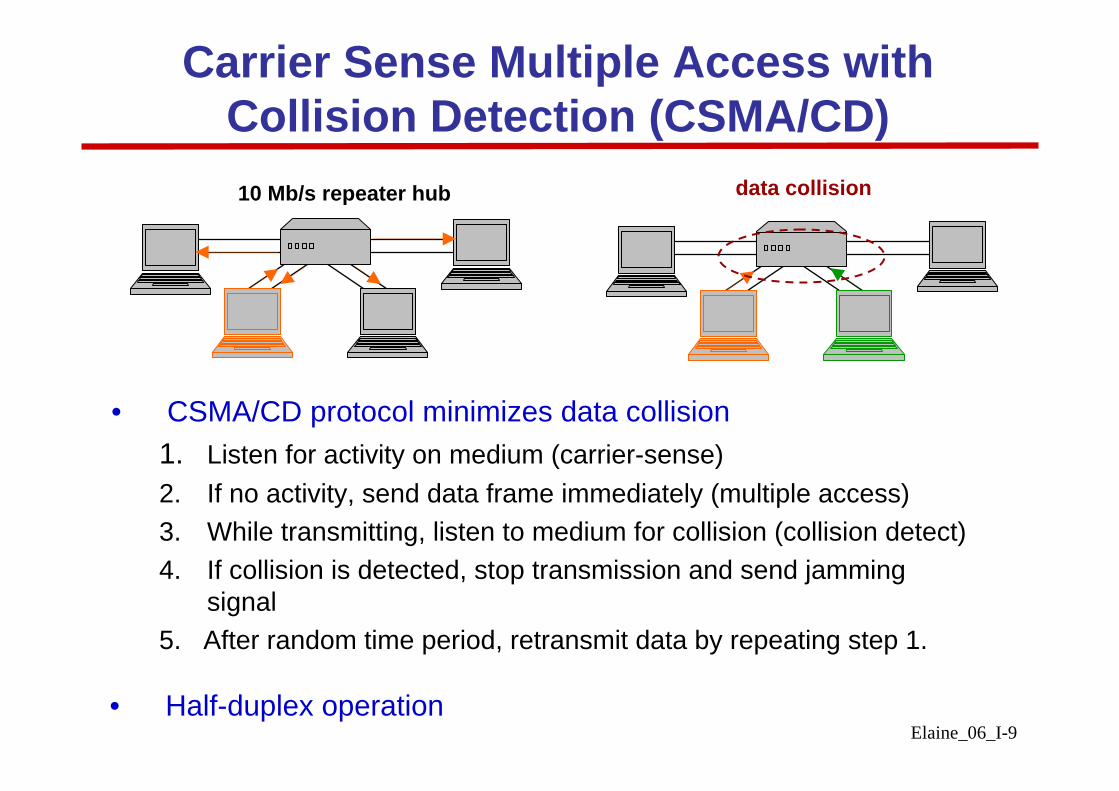
Carrier Sense Multiple Access with Collision Detection (CSMA/CD)10 Mb/s repeater hub data collision
• CSMA/CD protocol minimizes data collision1. Listen for activity on medium (carrier-sense)2. If no activity, send data frame immediately (multiple access)3. While transmitting, listen to medium for collision (collision detect)4. If collision is detected, stop transmission and send jamming
signal5. After random time period, retransmit data by repeating step 1.
• Half-duplex operation

Elaine_06_I-10
10 Mb/s Ethernet• In 1993, IEEE extended Ethernet to operate over optical fiber
transmission medium (IEEE 802.3j 10BASE-F)
• Three types of physical layer specifications: 10BASE-FP (fiberpassive), 10BASE-FL (fiber link), 10BASE-FB (fiber backbone)
62.5 μm MMF pair62.5 μm MMF pair
62.5 μm MMF pair
Transmission medium
850 nm850 nm850 nmTransmissionWavelength
10 Mb/s10 Mb/s10 Mb/sData Rate
10BASE-FB10BASE-FL10BASE-FP
Point-to-point linkPoint-to-point linkPassive starTopology
2 km2 km500 mMax. distance

Elaine_06_I-11
100 Mb/s Ethernet (Fast Ethernet)• In 1995, IEEE improved performance of Ethernet by a factor of 10
with 100 Mb/s standard (Fast Ethernet)
• One physical layer specification for the optical fiber transmission medium: 100BASE-FX
412 m (half-duplex) 2 km (full-duplex)
Max distance
62.5 μm MMF pairTransmission medium
850 nmTransmission wavelength100 Mb/sData Rate
100BASE-FX

Elaine_06_I-12
Switched Ethernet
• Data frames switched from one input link to one output link
• Simultaneously switching can performed on multiple input-output links without collision
• Switching hub can support mixed capacity links,i.e. 10 Mbps / 100 Mbps
• Fast Ethernet can operate in one of two modeshalf-duplex (CSMA/CD MAC protocol)full duplex (switched Ethernet protocol)
switching hub

Elaine_06_I-13
1 Gb/s Ethernet (Gigabit Ethernet)• In 1998, IEEE improved performance of Ethernet by a factor of 10
with 1 Gb/s standard (Gigabit Ethernet, GbE)
• Target application: backbone LAN
• Half-duplex and full-duplex operation
• Two GbE physical layer specifications for optical fibertransmission: 1000BASE-SX, 1000BASE-LX
5 km for SMF,550 m for MMF
550 m (50 μm) or 275 m (62.5μ)
Max distance
10 μm SMF pair,50 μm or 62.5 μm MMF pair
50 μm or 62.5 μm MMF pair
Transmission medium
1310 nm850 nmTransmission wavelength1 Gb/s1 Gb/sData Rate
1000BASE-LX1000BASE-SX

Elaine_06_I-14
10 Gb/s Ethernet (10GbE)• In June 2002, IEEE 802.3 standard extended to include 10 Gb/s
transmission
• 10GbE expected to be deployed in LAN, MAN and WANSeamless transport of Ethernet frames across entire networkSimplifies network management, minimizes operational costs
• 10GbE specifies full duplex operation and optical fibertransmission medium
• 10GbE media types: 10GBASE-S, 10GBASE-L, 10GBASE-E and 10GBASE-LX4
40 km10 km300 mMax distance
10 μm SMF pair10 μm SMF pair62.5 μm MMF pairTransmission medium
1550 nm1310 nm850 nmTransmission wavelength10 Gb/s10 Gb/s10 Gb/sData Rate
10GBASE-E10GBASE-L10GBASE-S

Elaine_06_I-15
10GbE: 10GBASE-LX4• 10GBASE-LX4 designed for wavelength division multiplexed
(WDM) network
• Transmission of four simultaneous 2.5 Gb/s wavelength channels
300 m (MMF) and 10 km (SMF)Max transmission distance
10 μm SMF or 50 μm, 62.5 μm MMF pairTransmission medium
1270 nm to 1355 nmTransmission wavelength4 × 2.5 Gb/sData Rate
10GBASE-LX4
wavelength

Elaine_06_I-16
Fiber Distributed Data Interface (FDDI)

Elaine_06_I-17
• Target installations: high-speed workstation interconnections and backbone LANs, where network reliability is important
• Now not as widely deployed as the Ethernet family but remains asone of the first to be standardized for high-speed fiber-optic LAN applications
Overview• FDDI developed and standardized by American National
Standards Institute (ANSI) and later the International Organization of Standardization (ISO) in mid-80s
• Physical statistics:• Transmission medium multimode fiber (connectivity within
building, single-mode fiber (connectivity between buildings)• Network architecture dual counter-propagating rings • Maximum ring size 100 km per ring• Data rate 100 Mb/s

Elaine_06_I-18
FDDI: Network Architecture
primary ring
secondary ring
• Each node connected to two rings via four fibers• During normal operation, data transmitted and received on
primary ring• Data frames passed from one node to another

Elaine_06_I-19
FDDI: Self-Healing Network
link failureloop back
loop back
• During node or link failure, secondary ring closes loop to restore all traffic transport
both primary and secondary rings in use
• Self-healing network is fault tolerate and increases network reliability

Elaine_06_I-20
Timed Token Rotation Protocol (TTRP)
• FDDI uses TTRP to control network access between nodes that share the network
• During network initialization or power up, pre-assigned node transmits special frame “TOKEN” onto the ring
• TOKEN circulates ring network from one node to the next
• TOKEN “passport” to transmit data

Elaine_06_I-21
• To transmit, a node• waits for TOKEN• captures TOKEN (without retransmitting back into the
network)• immediately transmits data frames• release TOKEN (append TOKEN to end of data frame)
• Transmitting (source) node removes data frame from network after one roundtrip propagation around the ring
TTRP (cont.)

Elaine_06_I-22
Transmissions from Node A-C, and B-A
• Node A waits and captures TOKEN• Node A transmits frame FA addressed to Node C• Node B regenerates and retransmits frame FA as it circulates past• Destination Node C copies and retransmits frame FA as it
circulates past• Node A appends TOKEN at the end of FA

Elaine_06_I-23
Transmissions from Node A-C, and B-A
• Node B captures TOKEN issued by Node A• Node B transmits frame FB addressed to Node A• Eventually, frame FA recirculates back to its source, Node A,
and is removed by Node A (no retransmission)• Meanwhile, Node B finishes transmitting FB and appends
TOKEN to FB

Elaine_06_I-24
Transmissions from Node A-C, and B-A
• Destination Node A copies FB, and regenerates FB and TOKEN at end of FB
• Frame FB is removed by its source, Node B, from the ring• Node B regenerates TOKEN• TOKEN will remain circulating around the ring until a node
wanting to transmit data frames will capture it for the right totransmit

Elaine_06_I-25
Data Frame Format
• Each node in the ring network is assigned a unique MAC address
• MAC addresses used in data frames to distinguish between source and destination nodes
PA DA SA DATA FS
single data frame• FDDI data frame comprises nine different fields• PA field – contains preamble• DA field – contains destination address
(MAC address of node that the data frame is intended for)

Elaine_06_I-26
Data Frame Format (cont.)
PA DA SA DATA FS
single data frame
• SA field – contains source address (MAC address of node transmitting data frame)
• DATA field – contains data information for destination node• Each node checks the DA and SA fields of every incoming
data frame• If DA field matches node’s own MAC address
copy entire DATA field and pass on the upper networking layers
• If SA field matches node’s own MAC address remove frame from the ring

Elaine_06_I-27
• FS – frame status (for checking correct reception of data frame)• Contains indicator bits – address recognized (A), and
frame copied (C)• Node sets A indicator to ‘1’ if DA field matches own MAC add• Node sets C indicator to ‘1’ after copying entire DATA field• FS field is checked when data frame recirculates back to source
node• If A and C are not set i.e. ‘0’, then destination node does not
exist or is inactive• If A = ‘1’ and C = ‘0’, DATA field not copied by active destination
node issue retransmission
Frame Status
PA DA SA DATA FS
single data frame
Elaine_06_I-28
• Prevent nodes from dominating network capacity• During network initialization, each node negotiates a
guaranteed maximum capacity to transmit high priority frames
• A global target token rotation time (TTRT) is stored at all nodes
• During network operation, each node measures successive arrivals of the TOKEN with a token rotation time (TRT)
• When TOKEN arrives and TRT < TTRTsend both high and then low priority frames
• When TOKEN arrives and TRT > TTRTonly send high priority frames
Time Controlled Mechanism

Elaine_06_I-29
Summary
• Ethernet family remains the most prevalent
availability of low chip-sets
mature and familiar management and analysis tools
• Fiber-optic LANs will continue to grow
higher speeds and larger coverage areas
• Future beyond 10 Gb/s will depend on wavelength division multiplexing (WDM) technology