Volume 5, Number 1, January - June 2020 ISSN: 2503-4219 (p ...

NATIONAL CORRUGATED STEEL PIPE ASSOCIATION14070 Proton Road • Ste. 100, LB 9 • Dallas, TX • 75244
(972) 850-1907 • Fax (972) 490-4219
Design Data Sheetsare for guidance only.
They require an experiencedP.E. for proper application.
June 1995
NCSPA DESIGN DATA SHEET NO. 19 LOAD RATING AND STRUCTURAL EVALUATION OFIN-SERVICE, CORRUGATED STEEL STRUCTURES
d. Mid-ordinate of each radius arc segment(for multi radius structure shapes)
2. Unsymmetrical Structures, structuresdeflected more than 5% from design shape,or those that show localized distortionsrequire that the actual maximum radius bedetermined in those distorted areas as shownin Appendix B.2. Use two times the actualmaximum radius rather than the span instructural design checks. Typically thisprovides a conservative evaluation of thestructure.
3. Stability Considerations
a. Continued movement (shape change) ofthe structure is evidence that the structurerequires monitoring and further evaluationof the backfill or foundation conditions.
b. Stability must be investigated where:
1) Actual dimensions show a significantchange from design or as builtdimensions (i.e., typically more than5%).
2) Pavement has settled or broken upover or immediately adjacent to thestructure.
3) There is evidence of backfill materialinfiltrating into the structure.
c. Monitoring structures for movementrequires repeating the measurements(above) on a regular basis, over areasonable period of time, usingpermanently marked measurement pointsand survey methods accurate to 0.01 ft.
4. Structures with riveted, bolted or weldedlongitudinal seams must be visuallyevaluated for proper plate nesting at the laps.
LOAD RATING AND STRUCTURAL EVALUATlON OFIN-SERVICE, CORRUGATED STEEL STRUCTURES
Load rating, and other structural evaluations ofin-service corrugated steel structures, is a two-step
process. As with any major structure, both a completefield evaluation of the structure’s condition, as well asan analytical evaluation of that structure’s load carryingcapabilities are required. The analytical evaluation isbased on the structure’s actual in-service shape andcondition, as well as actual field and design loadingneeds.
• The FHWA CULVERT lNSPECTION MANUAL (Ref. 1)provides the field inspection requirements, as well asother guidance and safety concerns.
• The AASHTO STANDARD SPECIFICATION FORHIGHWAY BRIDGES (Ref. 2) provides the basis foranalytical evaluations. The following general outlinesupports the engineer in combining the two resourcesfor a proper, in-service evaluation or load rating.
I. SURVEY OF FIELD CONDITIONS(Ref. Report FHWA-IP-86-2; July, 1986)
A. In-Service Dimensions:
1. All structures require that actual, in-servicedimensions be recorded throughout theirentire length. Care must be taken tomeasure the true rise of box culvert and archstructures to avoid inaccuracies due touneven inverts, bowed or bulged invert plates,burial depth to footings, etc.A surveyor's level, string lines across thestructure or other equal means are typicallynecessary for accurate measurements.These measurements include:
a. Span
b. Rise
c. Symmetry (uniform curvature).A symmetrical structure has its maximumrise point located above center span.
NCSPA DESIGN DATA SHEET NO. 19 LOAD RATING AND STRUCTURAL EVALUATION OFIN-SERVICE, CORRUGATED STEEL STRUCTURES
5) Where significant metal loss is limitedto the central portion of the invert,metal loss considerations just abovethe affected area may be significant tothe structural evaluation if the invert isrepaired.
6) Where substantial invert perforationhas occurred a determination of thedegree of structural degradation due tothe possible erosion of bedding andbackfill materials must be made.Significant loss of bedding and backfillwill reduce structural strength andstability quickly. Invert paving or otherrepair may be warranted.This paragraph applies to perforationsat any location.
7) Steel box culverts are bending momentdesign structures.
a) Invert plates are not structural,but bedding and backfill lossconsiderations apply.
b) Metal loss of the haunch and crownplates typically does not result in anequal reduction in bending strengthif external ribs are not similarlyaffected.
b. Structural Damage, such as dents andtears can be mitigated by bolting orwelding a new curved structural memberover the damaged section to replace thelost wall area. Appropriate measures mustbe taken to prevent future loss of beddingor backfill.
C. Footing Evaluation of Arches and BoxCulverts on footings or footing pads
1. Undermined footings, due to scour or otherattack, must be repaired to provide adequatesupport for the structure.
2. Repaired footings (and other footings thatshow signs of significant scour) must beprotected from further erosion using meanssuch as:
a. Rip Rap
b. Invert pavement
a. Cusped or open seams may suggest areduced allowable seam strength.
b. Bolt torque is not critical to seam strengthas long as bolts are tight and the platesare properly meshed.
c. Missing bolts, rivets or cracked platesneed to be replaced or repaired.
B. Material Evaluation
1. Actual fabricated material in place must berecorded at each measurement location. Theplans and specifications typically provide thisincluding:
a. Material thickness in 0.000 inches.
b. Corrugation or rib pitch and depth.
c. For box culverts and other structures withribs, rib size or type and spacing in thehaunch and crown area (as applicable).Ribs may be provided on the outside,inside or both sides of a box culvert.The external rib spacing can typically bedetermined by noting the location of theattachment bolts from the interior.
2. Durability Factors
a. Metal loss evaluation is normally focusedon the structure’s invert. Visual checks areneeded to confirm unusual loss elsewhere.
1) Where the galvanizing is intact andpitting has not occurred, steelstructures can typically be assumed tomaintain full design properties.
2) If galvanizing or other coating is gone,or abrasion loss of the base metal isevident, but the invert is not perforated,core the structure for a metal thicknessevaluation.
3) The occurrence of first perforation fromsoil side corrosion typically indicates a13% metal loss in steel structures.
4) For conditions beyond first perforation,a metal loss determination is made bycoring the structure.
2

NCSPA DESIGN DATA SHEET NO. 19 LOAD RATING AND STRUCTURAL EVALUATION OFIN-SERVICE, CORRUGATED STEEL STRUCTURES
D. Actual and Design Load Evaluation
1. Height of Cover
a. For a complete structural evaluationdetermine:
1) Maximum height of cover.
2) Minimum height of cover in areassubject to traffic.
3) Repeat the above for each portion ofthe structure when dictated by:
a) Structure wall thickness or profilechanges.
b) Structure condition changes.
4) For load rating, the above height ofcover considerations only apply toareas subject to traffic.
2. Record actual and design loads over thestructure.
II. STRUCTURAL EVALUATION(Ref. AASHTO Standard Specification for HighwayBridges, Division I, Section 12)
Structural evaluation should use A or B, depending on in-service conditions
A. Dimensions for Design1. For typical structures, use the actual field
measured span for calculations.
2. For unsymmetrical structures or thosedeflected over 5%:
a. Use two times the top radius (2Rt) in lieuof span for calculations.
b. Base critical buckling stress calculationson the theoretical design span, reducingthe resulting allowable buckling stress bythe appropriate multiplier to account fordeflection, as shown in Figure B.1.1 inAppendix B.1
3. For all long span structures (horizontalellipse, low and high profile arches, invertedpear shapes and pear arches), as well asother horizontal ellipses, use two times actualtop radius (2Rt) in all cases.
4. Box culvert moments are based on the actualspan and increased for deflection such that:
a. Crown deflection (reduction in rise) lessthan 1% of span—no increase.
b. Crown deflection (reduction in rise) of 1 to3% of span—increase dead and live loadmoments by CH (Ref. 4).
Where: CH = 1.15 - (H-1.4)14
c. Crown deflection (reduction in rise) greaterthan 3% of span—special analysis isrequired.
B. Design Properties
1. Reduce section properties on the basis ofmetal loss from the materials evaluation.
a. Reduce properties of non-box culvertstructures on an equivalent (percent) tometal loss basis. Where significant metalloss is limited to the bottom quadrant(invert), thrust in this area may be moreaccurately calculated using ring formulae(Ref. 5).
b. Box Culverts
1) Invert plates are not structural and donot bear on calculations. However, theymust be able to protect against scour.
2) When metal loss is limited to the plateportion of the shell only, reducemoment capacity by interpolatingbetween values from the appropiatetables in Appendix D, using the actualthickness of the plate.
3) When metal loss is uniform over plateand ribs, reduce moment capacity onthe basis of the percent of metal loss.
2. Seam Strength depends upon proper nestingand smooth plate alignment as well as sheetor plate gage. AASHTO requires a seamstrength Factor of Safety of 3.0 while otherdesign methods, such as that offered by theAmerican Iron and Steel Institute, require afactor of 2.0. This difference can allow for areasonable variance of seam characteristicswithout a practical loss of safety and
3

NCSPA DESIGN DATA SHEET NO. 19 LOAD RATING AND STRUCTURAL EVALUATION OFIN-SERVICE, CORRUGATED STEEL STRUCTURES
III. LOAD RATING(Applicable only to sections carrying traffic. Followall structure evaluation guidance and basecalculations on H20, 32 KIP axle)
A. Basic AASHTO Equations:
Max. Strength = 1.3 [βD + RF (L+I)] - Operating Load
Max. Strength = 1.3 [βD + 5 RF (L+I)] - Inventory Load3
1. Where:
a. Maximum Strength is the maximum designstrength
b. RF = Rating Factor
c. D = Dead Load
d. L + I = Live Load + Impact
e. 1.3 = Load Factor γ
f. β = Load Factor.Note: β = 1.0 for conventional bridges;
β > 1.0 for flexible pipes.
2. For corrugated steel structures
a. Maximum strength is:
1) Max. allowable thrust (Tcap) for ringcompression structures.
2) Maximum allowable moment (Mcap) forbox culverts.
b. Dead load is the earth cover load:
1) TE; earth load thrust for ringcompression structures.
2) ME; earth load bending moment for boxculverts.
c. Total earth load, load factor (β x γ)required is:
1) 1.95 for ring compression structures.Therefore, β = 1.5
2) l.50 for box culverts. Therefore,β = 1.15
serviceability.
a. Bolt torque is not critical to strength aslong as bolts are tight and the plates areproperly nested.
b. Missing bolts should be replaced.They can be accounted for in structuralcalculations by a ratio of the number ofbolts present to the number assumed intabulated strength values.
c. If there is metal loss in the seam area,reduce seam strength by interpolatingbetween the seam strength for adjacentgage thicknesses vs. actual thickness.
C. Design Calculations
1. Follow AASHTO Bridge SpecificationMethods as referenced. Flexibility Factorevaluations, which bear only on installationstiffness, are not applicable since thestructure is already in place.
2. Evaluate each section of the structure alongits length.
a. Sections are determined by:
1) Thickness (gage) changes in pipe wallsor plates.
2) Changes in shape or materialcondition.
b. Check each section at points of:
1) Maximum cover
2) Minimum cover in areas subject totraffic. Minimum cover requirements donot apply in sections without trafficloads.
3. Where less than minimum cover conditionsexist in traffic areas with special backfillmaterials, load relief slabs, or special design,a special analysis is required.
4

NCSPA DESIGN DATA SHEET NO. 19 LOAD RATING AND STRUCTURAL EVALUATION OFIN-SERVICE, CORRUGATED STEEL STRUCTURES
B. Rating Factors (RF), Ring CompressionStructures1. Operating Load Rating Factor (RFo) is the
lower of the two values based on wallstrength or minimum cover requirements.
a. RFo based on wall strength.
RFo-w=Tcap-1.95TE1.3T(L+I)
1) Tcap equals thrust capacity of the wall.It is the lesser of:
a) Wall Yield Strength = FyA
b) Wall Buckling Strength = Fcrit A
and, for pipes with riveted, welded orbolted seams, a third factor:
c) Seam Strength = 0.67 x (seamstrength)
2) TE equals pipe wall thrust due to earthcover and is the higher value of:
a) δH (S/2)
b) δH Rt
3) T(L + I) equals pipe wall thrust due tolive load plus impact (See Appendix C)and is the greater of:
a) (PL + I )S/2
b) (PL + I )Rt
b. RFo based on minimum cover requirements
RFo-c= H2 (See Appendix E)C(h)2
1) H is the lowest actual cover over thestructure in a traffic area based on fieldmeasurement.
2) h is the AASHTO minimum cover levelfor the structure (Ref. 2, Sections12.4.1.5, 12.5.3.3, 12.6.1.5 or 12.7.2.1)
3) C = 2.36 H/S + 0.528 1.0(See Appendix E)
2. Inventory Load Rating Factor (RFi) can bedetermined from the operating load ratingFactor (RFo) or from minimum coverrequirements. It is the lowest value of:
a. RFi = 3 RFo-w5
b. RFi = H2 (See Appendix E)h2
1) H is the lowest actual cover over thestructure in the traffic area based onfield measurement.
2) h is the AASHTO minimum cover levelfor the structure (Ref. 2, Sections12.4.1.5, 12.5.3.3, 12.6.1.5, or 12.7.2.1)
C. Rating Factor (RF) for Steel Box Culverts
COMMENTARY: Metal box culverts distributemoment between their haunch and crown on thebasis of their relative stiffness (moment capacity).This is accommodated in design by a range ofproportioning factors, P, (AASHTO Section 12.8,Table 12.8.4 D) provided in the design specification.
To properly rate a metal box culvert, the valueof P selected from the allowable range mustassign moment to the haunch and crown suchthat the same percentage of the availablemoment capacity of each is utilized. Using thatspecific value of P, the structure may be rated byload rating either the haunch or the crown.
Where limits on the proportioning factor (P)do not allow for the equal utilization of availablehaunch and crown moment capacity, load ratingmust be based on that portion (haunch or crown)that experiences the greatest utilization of itsmoment capacity. This is done by selecting a pro-portioning factor (P) at one extreme end of theallowable range such that as much moment aspossible is assigned to the under utilizedportion (haunch or crown).
1. Operating Load Rating Factor (RFo)
a. RFo =M cap - 1.5 M ECH
1.3 (ML+ I)CH
b. Rating the crown
1) Mcap is the moment capacity of thecrown (Mp) adjusted for conditionfactors as shown in the appropiatetable in appendix D.
5

NCSPA DESIGN DATA SHEET NO. 19 LOAD RATING AND STRUCTURAL EVALUATION OFIN-SERVICE, CORRUGATED STEEL STRUCTURES
3) ML + I is the live load plus impactmoment assigned to the haunch basedon the actual minimum cover in thetraffic area (field measurement):
ML + I = (Rh CLL MLL / 2)(1-P)
Where: P is the proportioningfactor selected as discussed in thecommentary.
4) CH is an adjustment factor forin-service shape:
a) CH = 1.0 if the crown (reduction inrise) is deflected less than 1% ofspan from design shape.
b) CH = 1.15 - (H-1.4) Ž 1.014
if crown deflections (reduction inrise) of 1-3% of span from designshape (Ref. 4).
c) For crown deflections (reduction inrise) exceeding 3% of span, aspecial analysis is required.
2. Inventory Load Rating Factor (RFi)
RFi = 3 RFo5
D. Loading Rating (Based on H/HSTruck)
1. Operating Loads
a. Axle Load = RFo (32) (in kips)
b. H/HS Truck = RFo (GVW)
1) H Truck = RFo (20) (in tons)
2) HS Truck = RFo (36) (in tons)
2. Inventory Loads
a. Axle Load = RFi (32) (in kips)
b. H/HS Truck = RFi (GVW)
1) H Truck = RFi (20) (in tons)
2) HS Truck = RFi (36) (in tons)
2) ME is the earth load moment assignedto the crown based on the actualminimum cover in the traffic area asfield measured, where:
ME = (Cdl Mdl/1.5)P(Ref.2, Section 12.8.4.3)
Where: P is the proportioningfactor selected as discussed in thecommentary.
3) ML+I = (CLL MLL/2)P(Ref. 2, Section 12.8.4.3)
Where: P is the proportioning factorselected as discussed in thecommentary.
4) CH is an adjustment factor for thein-service shape:
a) CH = 1.0 if the crown (reduction inrise) is deflected less than 1% ofspan from design shape.
b) CH = 1.15 - H-1.4 > 1.014
if crown deflections (reduction inrise) of 1-3 % of span from designshape (Ref. 4).
c) For crown deflections (reduction inrise) exceeding 3% of span, aspecial analysis is required.
c. Rating the Haunch
1) Mcap is the moment capacity of thehaunch (MP) adjusted for conditionfactors (See Appendix D)
2) ME is the earth load (dead load)moment assigned to the haunch basedon the actual minimum cover in thetraffic zone from field measurement:
ME = (Cdl Mdl / 1.5)(1-P)(Ref. 2, Section 12.8.4.3)
Where: P is the proportioningfactor selected as discussed in thecommentary.
6
NCSPA DESIGN DATA SHEET NO. 19 LOAD RATING AND STRUCTURAL EVALUATION OFIN-SERVICE, CORRUGATED STEEL STRUCTURES
A. NOMENCLATUREA = Pipe wall cross section area (in2 /ft.)C = Minimum cover factor of safety adjustment
Cdl = Box culvert dead load adjustment coefficient(AASHTO Section 12.0)
CH = Box culvert moment adjustment coefficient due toshape
CLL = Box culvert live load adjustment coefficient(AASHTO Section 12.0)
Fy = Material yield strength (psi)Fcrit = Critical buckling strength (psi-See AASHTO
Section 12)H = Height of cover (ft.)
h = AASHTO live load minimum coverrequirement over structure (ft.)
I = Impact portion of live load (See Appendix C)
Mcap = Moment Strenght, Mp (ft - K/ft.)
Mdl = AASHTO factored box culvert moment due to dead(earth) load (ft-k/ft.)ME = Box culvert moment due to earth load (ft-k/ft.)
M L+I = Box culvert moment due to live load plusimpact (ft-k/ft.)
MLL = AASHTO factored box culvert moment due tolive load plus impact
P = AASHTO moment proportioning factor for boxculverts (AASHTO Section 12.0)
PD = Pressure at the crown of the pipe due to dead(earth) load (lbs./ft.2)
P L+I = Pressure at the crown of the pipe due to live loadplus impact (lbs./ft.2)
RF = Rating FactorRFo = Operating load rating factorRFI = Inventor load rating factorRFo-w = Operating load rating factor based on wall strength
RFo-c = Operating load rating factor based on
minimum coverRt = Top radius of pipe (ft.)S = Span of pipe (ft.)T = Ring compression pipe wall thrust (lbs./ft.)TE = Thrust due to dead (earth) loads (lbs./ft.)Tcap = Pipe wall thrust capacity (lbs./ft.)T(L+I) = Thrust due to live load plus impact (lbs./ft.)δ = Soil Density (pcf)
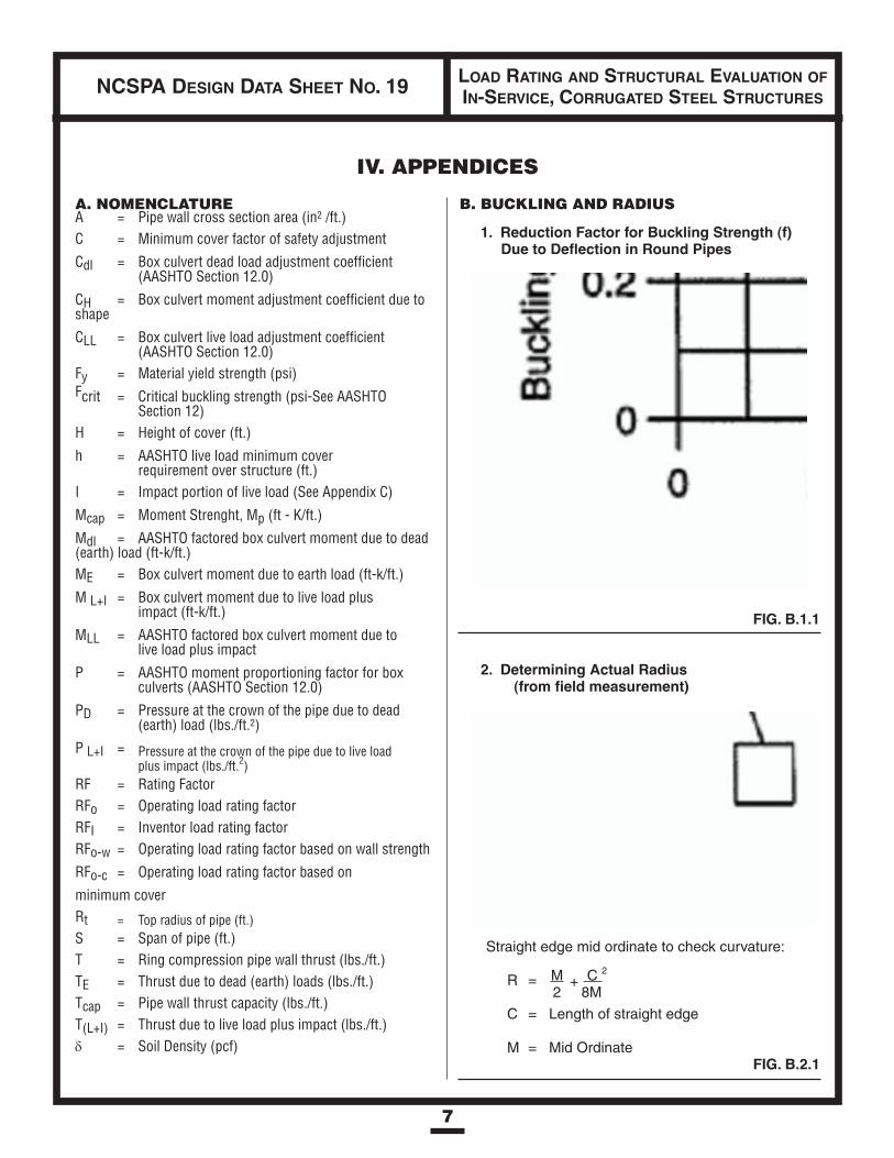
B. BUCKLING AND RADIUS
1. Reduction Factor for Buckling Strength (f)Due to Deflection in Round Pipes
FIG. B.1.1
2. Determining Actual Radius(from field measurement)
7
Straight edge mid ordinate to check curvature:
R = M + C 2
2 8M
C = Length of straight edge
M = Mid OrdinateFIG. B.2.1
IV. APPENDICES
8
NCSPA DESIGN DATA SHEET NO. 19 LOAD RATING AND STRUCTURAL EVALUATION OFIN-SERVICE, CORRUGATED STEEL STRUCTURES
APPENDICES (CONTINUED)
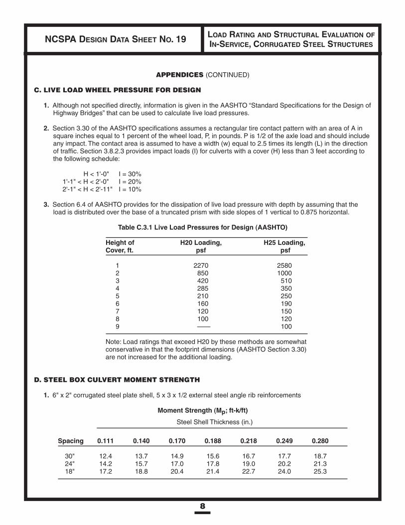
C. LIVE LOAD WHEEL PRESSURE FOR DESIGN
1. Although not specified directly, information is given in the AASHTO “Standard Specifications for the Design ofHighway Bridges” that can be used to calculate live load pressures.
2. Section 3.30 of the AASHTO specifications assumes a rectangular tire contact pattern with an area of A insquare inches equal to 1 percent of the wheel load, P, in pounds. P is 1/2 of the axle load and should includeany impact. The contact area is assumed to have a width (w) equal to 2.5 times its length (L) in the directionof traffic. Section 3.8.2.3 provides impact loads (I) for culverts with a cover (H) less than 3 feet according tothe following schedule:
H < 1'-0" I = 30%1'-1" < H < 2'-0" I = 20%2'-1" < H < 2'-11" I = 10%
3. Section 6.4 of AASHTO provides for the dissipation of live load pressure with depth by assuming that theload is distributed over the base of a truncated prism with side slopes of 1 vertical to 0.875 horizontal.
Table C.3.1 Live Load Pressures for Design (AASHTO)
Height of H20 Loading, H25 Loading,Cover, ft. psf psf
1 2270 25802 850 10003 420 5104 285 3505 210 2506 160 1907 120 1508 100 1209 —— 100
Note: Load ratings that exceed H20 by these methods are somewhatconservative in that the footprint dimensions (AASHTO Section 3.30)are not increased for the additional loading.
D. STEEL BOX CULVERT MOMENT STRENGTH
1. 6" x 2" corrugated steel plate shell, 5 x 3 x 1/2 external steel angle rib reinforcements
Moment Strength (Mp; ft-k/ft)Steel Shell Thickness (in.)
RibSpacing 0.111 0.140 0.170 0.188 0.218 0.249 0.280
30" 12.4 13.7 14.9 15.6 16.7 17.7 18.724" 14.2 15.7 17.0 17.8 19.0 20.2 21.318" 17.2 18.8 20.4 21.4 22.7 24.0 25.3

9
NCSPA DESIGN DATA SHEET NO. 19 LOAD RATING AND STRUCTURAL EVALUATION OFIN-SERVICE, CORRUGATED STEEL STRUCTURES
APPENDICES (CONTINUED)
2. 6" x 2" Corrugated Steel Plate Shell, Corrugated Plate Stiffener Ribs (6" x 3" Corrugation)
Moment Strength (Mp; ft-k/ft)Steel Shell Thickness (in.)
Rib Thicknesses Rib Spacing 0.111 0.140 0.170 0.188 0.218
0.11" 24" Exterior 6.4 7.3 8.012" Exterior 9.4 10.7 11.924" Exterior & Interior 12.0 12.9 13.8
0.140" 24" Exterior 7.4 8.4 9.2 9.912" Exterior 11.1 12.5 13.7 14.524" Exterior & Interior 14.6 15.6 16.6 17.2
0.170" 24" Exterior 8.3 9.5 10.4 11.0 11.812" Exterior 12.0 14.4 15.2 16.2 17.524" Exterior & Interior 17.5 18.3 19.0 19.5 20.3
0.188" 24" Exterior 10.1 11.1 11.7 12.612" Exterior 14.7 16.2 17.2 18.624" Exterior & Interior 20.0 20.8 21.3 22.0
0.218" 24" Exterior 12.1 12.8 14.212" Exterior 17.7 18.8 20.224" Exterior & Interior 23.6 24.0 24.8
0.249 24" Exterior 13.9 15.112" Exterior 20.0 21.924" Exterior & Interior 26.8 27.6
3. 15" x 5-1/2" Corrugated Steel Pipe Shell (No Rib Reinforcements) Material with corrugation crests orvalleys that have been crimped or otherwise embossed to facilitate curving, do not apply.
Moment Strength (Mp; ft-k/ft)Steel Shell Thickness (in.)
0.140 0.170 0.188 0.218 0.249 0.280 0.318 0.377
Mp (Ft-k/ft) 10.8 13.2 14.8 17.3 19.8 22.3 25.3 30.4
10
NCSPA DESIGN DATA SHEET NO. 19 LOAD RATING AND STRUCTURAL EVALUATION OFIN-SERVICE, CORRUGATED STEEL STRUCTURES
APPENDICES (CONTINUED)
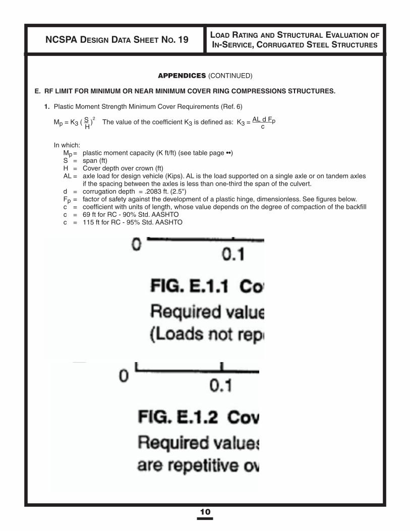
E. RF LIMIT FOR MINIMUM OR NEAR MINIMUM COVER RING COMPRESSIONS STRUCTURES.
1. Plastic Moment Strength Minimum Cover Requirements (Ref. 6)
Mp = K3 ( S )2
The value of the coefficient K3 is defined as: K3 =AL d Fp
H c
In which:Mp= plastic moment capacity (K ft/ft) (see table page ••)S = span (ft)H = Cover depth over crown (ft)AL = axle load for design vehicle (Kips). AL is the load supported on a single axle or on tandem axles
if the spacing between the axles is less than one-third the span of the culvert.d = corrugation depth = .2083 ft. (2.5")Fp = factor of safety against the development of a plastic hinge, dimensionless. See figures below.c = coefficient with units of length, whose value depends on the degree of compaction of the backfillc = 69 ft for RC - 90% Std. AASHTOc = 115 ft for RC - 95% Std. AASHTO

11
NCSPA DESIGN DATA SHEET NO. 19 LOAD RATING AND STRUCTURAL EVALUATION OFIN-SERVICE, CORRUGATED STEEL STRUCTURES
APPENDICES (CONTINUED)
2. RF Limit Development
2.1 AASHTO minimum cover limits are span/8 for H20 live loads.
2.2 The required Factors of Safety Fp, for minimum covers of span/8 are:
Fp = 1.488 (for Inventory Loads – Fig. E.1.2)
Fp = 1.225 (for Operating Loads – Fig. E.1.1)
Fp operating/Fp inventory = 0.823
2.3 Basic equations in E.1, for a given structure and backfill condition, require minimum cover levelsthat increase linearly with increasing axle loads such that
Mp=K3 ( S )2 = AL d Fp ( S )2H c H
2.4 To maintain the Factor of Safety when axle loads are increased:
AL d Fp ( S )2 = RF (AL) d Fp ( S )2c h c H
RF = H2 Inventory loads, based on coverh2
2.5 To reduce the Factor of Safety for occasional (operating) loads, Figure E 2.5.1 has been developedfrom Fp values in E.1.
y = mx+b � C = 2.36 H + .528 < 1.0S
RF = H2 Operating loads based on coverCh2
NATIONAL CORRUGATED STEEL PIPE ASSOCIATION14070 Proton Road • Ste. 100, LB 9 • Dallas, TX • 75244
(972) 850-1907 • Fax (972) 490-4219
Design Data Sheetsare for guidance only.
They require an experiencedP.E. for proper application.
June 1995
NCSPA DESIGN DATA SHEET NO. 19 LOAD RATING AND STRUCTURAL EVALUATION OFIN-SERVICE, CORRUGATED STEEL STRUCTURES
This Data Sheet is for general use only and should not be used without firstsecuring competent engineering advice as to its suitability for any specific
application. The publication of this material is not intended as arepresentation or warranty on the part of the National Corrugated SteelPipe Association that such data and information are suitable for any
general or particular use or of freedom from infringement of any patent(s).Neither the NCSPA nor any of its members warrants or assumes liability asto its suitability for any given application. Anyone using this data sheet
assumes all liability arising from such use.
REFERENCES
1. FHWA Culvert Inspection Manual; Report FHWA-IP-86-2; July 1986.
2. AASHTO Standard Specification For Highway Bridges, 1992.
3. AASHTO; Manual For Maintenance Inspection Of Bridges;Washington, D.C., 1983.
4. Boulanger, Seed, Baird and Schluter; Measurements And Analysis of Deformed Flexible Box Culverts;Transportation Research Board Paper No. 880272; January, 1989.
5. Roark, R.J.; Formulas For Stress And Strain; McGraw-Hill.
6. Duncan, J.M. and Drawsky, R.H.; Design Procedures for Flexible Metal Culvert Structures;University of California, Berkeley, CA, Department of Civil Engineering, Report No. UCB/GT/83-02, May, 1983.
7. Installation Inspection Procedures For Long Span Corrugated Metal Structures, D.C. Cowherd and D.H. Degler,Report FHWA/OH-86/012.
8. Evaluation Procedures For Long Span Corrugated Metal Structures, Report by Bowser-Warner, Inc.420 Davis Ave., Dayton OH 45401; March 10, 1986