Load-sensing control block in sandwich plate design SB23-M
24
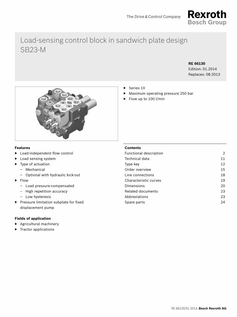
RE 66130/01.2014, Bosch Rexroth AG Features ▶ Load-independent flow control ▶ Load sensing system ▶ Type of actuation – Mechanical – Optional with hydraulic kick-out ▶ Flow – Load pressure-compensated – High repetition accuracy – Low hysteresis ▶ Pressure limitation subplate for fixed displacement pump Fields of application ▶ Agricultural machinery ▶ Tractor applications ▶ Series 1X ▶ Maximum operating pressure 250 bar ▶ Flow up to 100 l/min RE 66130 Edition: 01.2014 Replaces: 08.2013 Load-sensing control block in sandwich plate design SB23-M Contents Functional description 2 Technical data 11 Type key 12 Order overview 15 Line connections 18 Characteristic curves 19 Dimensions 20 Related documents 23 Abbreviations 23 Spare parts 24
Transcript of Load-sensing control block in sandwich plate design SB23-M
RE 66130/01.2014, Bosch Rexroth AG
Features ▶ Load-independent flow control ▶ Load sensing system ▶ Type of actuation
– Mechanical – Optional with hydraulic kick-out
▶ Flow – Load pressure-compensated – High repetition accuracy – Low hysteresis
▶ Pressure limitation subplate for fixed displacement pump
Fields of application ▶ Agricultural machinery ▶ Tractor applications
▶ Series 1X ▶ Maximum operating pressure 250 bar ▶ Flow up to 100 l/min
RE 66130Edition: 01.2014Replaces: 08.2013
Load-sensing control block in sandwich plate designSB23-M
ContentsFunctional description 2Technical data 11Type key 12Order overview 15Line connections 18Characteristic curves 19Dimensions 20Related documents 23Abbreviations 23Spare parts 24
Bosch Rexroth AG, RE 66130/01.2014
2 SB23-M Series 1X | Control blockFunctional description
Functional description
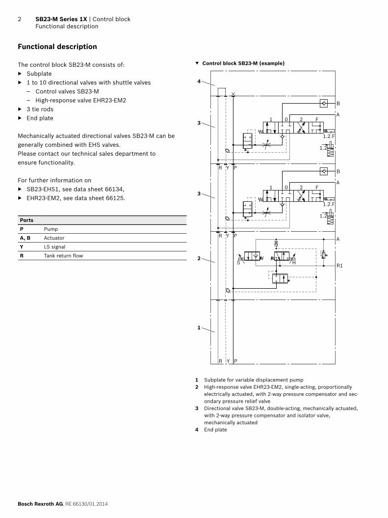
The control block SB23-M consists of: ▶ Subplate ▶ 1 to 10 directional valves with shuttle valves
– Control valves SB23-M – High-response valve EHR23-EM2
▶ 3 tie rods ▶ End plate
Mechanically actuated directional valves SB23-M can be generally combined with EHS valves.Please contact our technical sales department to ensure functionality.
For further information on ▶ SB23-EHS1, see data sheet 66134, ▶ EHR23-EM2, see data sheet 66125.
Ports
P Pump
A, B Actuator
Y LS signal
R Tank return flow
▼ Control block SB23-M (example)
Y PR
B
A
1.2
1.2.F
1 0 2 F
Y PR
B
A
A
1.2
1.2.F
1 0 2 F
R Y P
1
H R1S2
3
3
4
1 Subplate for variable displacement pump2 High-response valve EHR23-EM2, single-acting, proportionally
electrically actuated, with 2-way pressure compensator and sec-ondary pressure relief valve
3 Directional valve SB23-M, double-acting, mechanically actuated, with 2-way pressure compensator and isolator valve, mechanically actuated
4 End plate
RE 66130/01.2014, Bosch Rexroth AG
Control block | SB23-M Series 1X Functional description
3
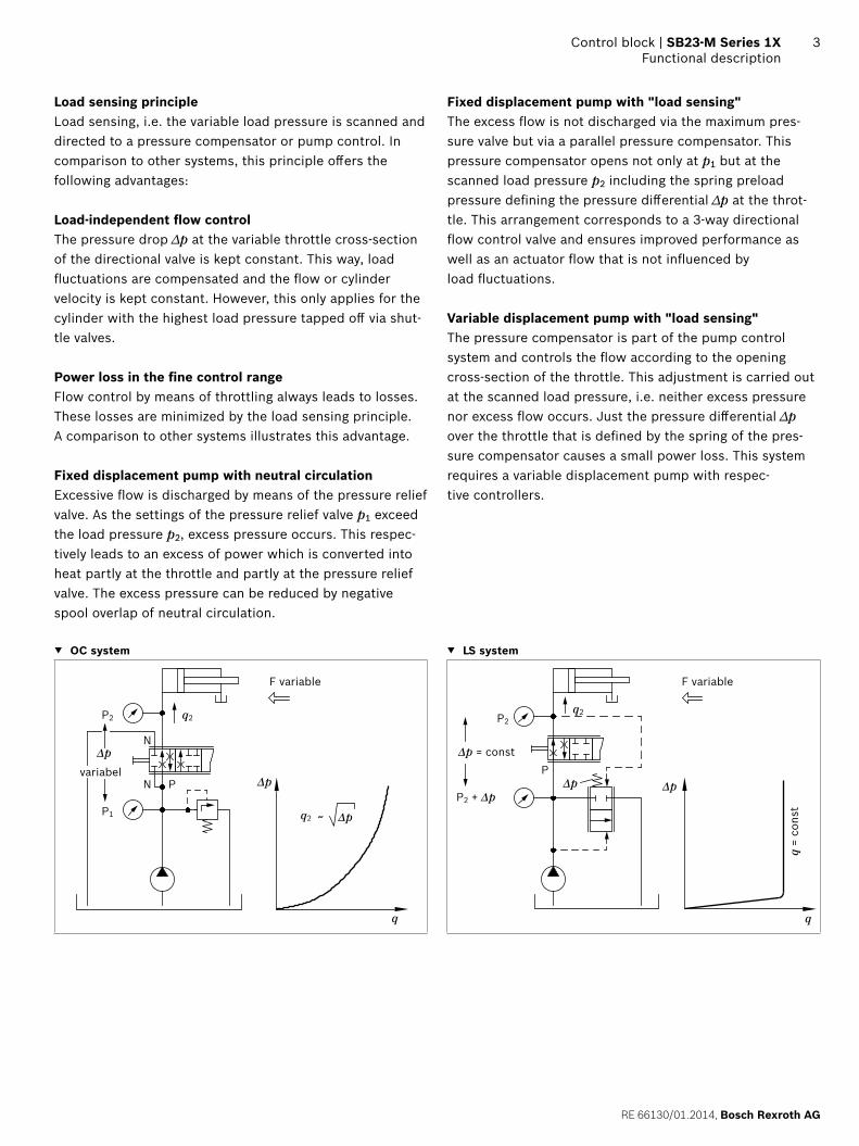
Load sensing principleLoad sensing, i.e. the variable load pressure is scanned and directed to a pressure compensator or pump control. In comparison to other systems, this principle offers the following advantages:
Load-independent flow controlThe pressure drop ∆p at the variable throttle cross-section of the directional valve is kept constant. This way, load fluctuations are compensated and the flow or cylinder velocity is kept constant. However, this only applies for the cylinder with the highest load pressure tapped off via shut-tle valves.
Power loss in the fine control rangeFlow control by means of throttling always leads to losses. These losses are minimized by the load sensing principle. A comparison to other systems illustrates this advantage.
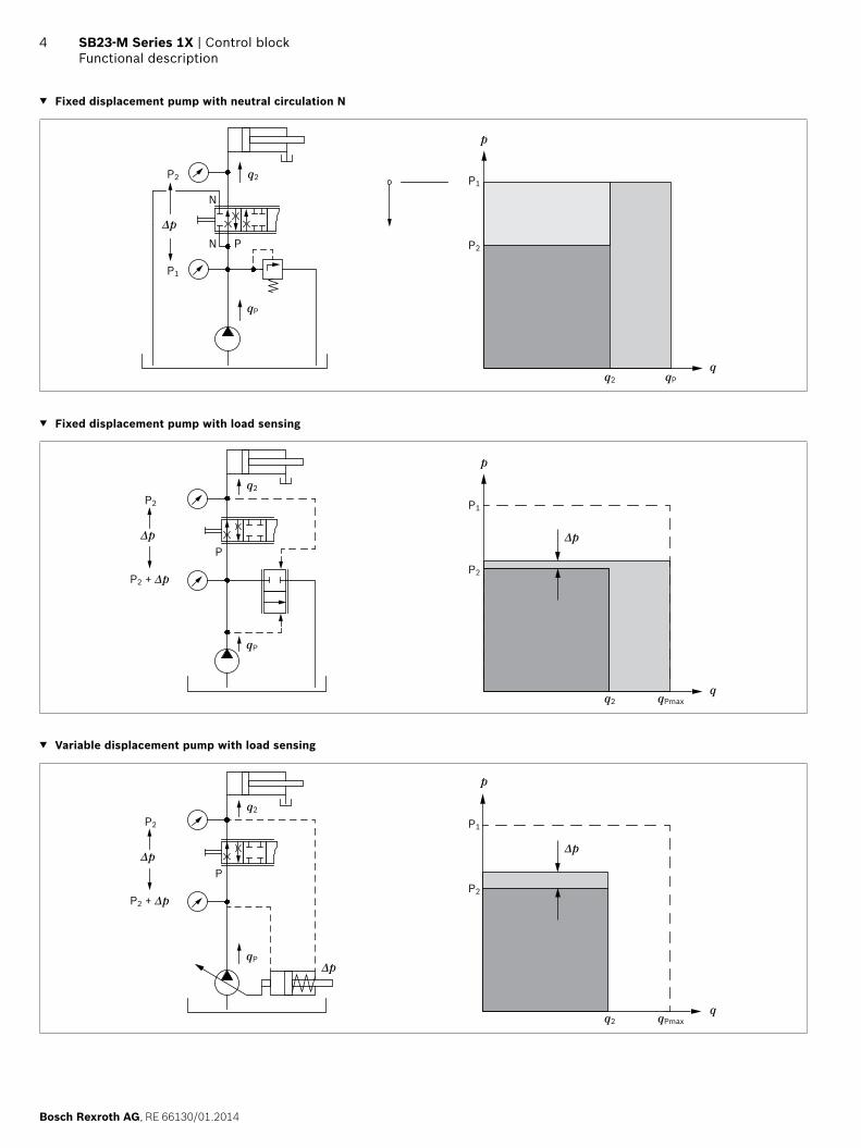
Fixed displacement pump with neutral circulationExcessive flow is discharged by means of the pressure relief valve. As the settings of the pressure relief valve p1 exceed the load pressure p2, excess pressure occurs. This respec-tively leads to an excess of power which is converted into heat partly at the throttle and partly at the pressure relief valve. The excess pressure can be reduced by negative spool overlap of neutral circulation.
Fixed displacement pump with "load sensing"The excess flow is not discharged via the maximum pres-sure valve but via a parallel pressure compensator. This pressure compensator opens not only at p1 but at the scanned load pressure p2 including the spring preload pressure defining the pressure differential ∆p at the throt-tle. This arrangement corresponds to a 3-way directional flow control valve and ensures improved performance as well as an actuator flow that is not influenced by load fluctuations.
Variable displacement pump with "load sensing"The pressure compensator is part of the pump control system and controls the flow according to the opening cross-section of the throttle. This adjustment is carried out at the scanned load pressure, i.e. neither excess pressure nor excess flow occurs. Just the pressure differential ∆p over the throttle that is defined by the spring of the pres-sure compensator causes a small power loss. This system requires a variable displacement pump with respec-tive controllers.
▼ OC system ▼ LS system
F variabel
variabelPN
N
q2
q2
P2
P1
Δp
Δp
Δp
q
q2P2
P2 + ΔpΔp
P
q
Δp
F variabel
q =
cons
t
Δp = const
F variableF variable
Bosch Rexroth AG, RE 66130/01.2014
4 SB23-M Series 1X | Control blockFunctional description
▼ Fixed displacement pump with neutral circulation N
PN
N
q2P2
P1
Δp
qP
q2 qP
P2
P1
p
q
▼ Fixed displacement pump with load sensing
P2
P1
Δp
p
q2 qPmaxq
q2
P2
P2 + Δp
PΔp
qP
▼ Variable displacement pump with load sensing
q2 qPmax
P2
P1
p
q
q2
P2
P2 + Δp
PΔp
Δp qP
Δp
RE 66130/01.2014, Bosch Rexroth AG
Control block | SB23-M Series 1X Functional description
5
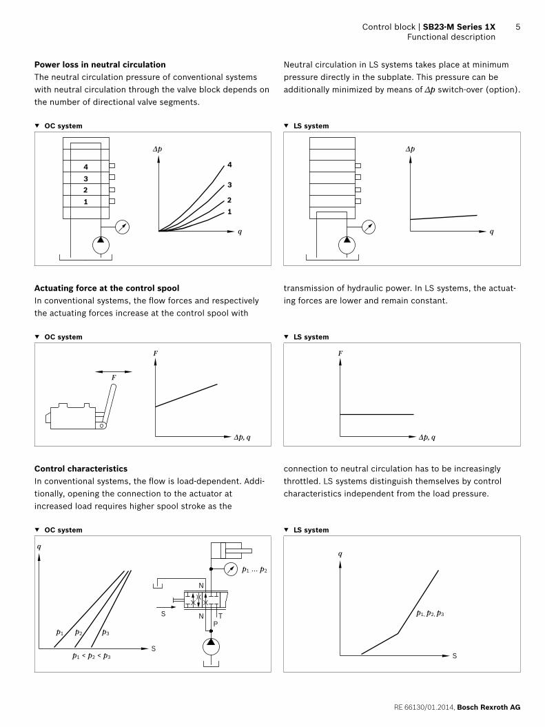
Power loss in neutral circulationThe neutral circulation pressure of conventional systems with neutral circulation through the valve block depends on the number of directional valve segments.
Neutral circulation in LS systems takes place at minimum pressure directly in the subplate. This pressure can be additionally minimized by means of ∆p switch-over (option).
▼ OC system ▼ LS system
q
Δp
4321
4
3
21
q
Δp
Actuating force at the control spoolIn conventional systems, the flow forces and respectively the actuating forces increase at the control spool with
transmission of hydraulic power. In LS systems, the actuat-ing forces are lower and remain constant.
▼ OC system ▼ LS system
Δp, q
F
F
Δp, q
F
Control characteristicsIn conventional systems, the flow is load-dependent. Addi-tionally, opening the connection to the actuator at increased load requires higher spool stroke as the
connection to neutral circulation has to be increasingly throttled. LS systems distinguish themselves by control characteristics independent from the load pressure.
▼ OC system ▼ LS system
p2p1 p3
p1 < p2 < p3
p1 ... p2
q
S
S N TP
N
p1, p2, p3
q
S
Bosch Rexroth AG, RE 66130/01.2014
6 SB23-M Series 1X | Control blockFunctional description
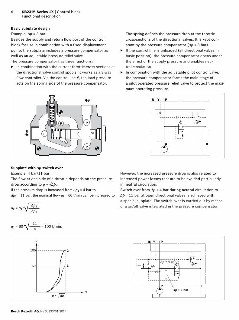
Basic subplate designExample: ∆p = 3 barBesides the supply and return flow port of the control block for use in combination with a fixed displacement pump, the subplate includes a pressure compensator as well as an adjustable pressure relief valve.The pressure compensator has three functions:
▶ In combination with the current throttle cross-sections at the directional valve control spools, it works as a 3-way flow controller. Via the control line Y, the load pressure acts on the spring side of the pressure compensator.
The spring defines the pressure drop at the throttle cross-sections of the directional valves. It is kept con-stant by the pressure compensator (∆p = 3 bar).
▶ If the control line is unloaded (all directional valves in basic position), the pressure compensator opens under the effect of the supply pressure and enables neu-tral circulation.
▶ In combination with the adjustable pilot control valve, the pressure compensator forms the main stage of a pilot operated pressure relief valve to protect the maxi-mum operating pressure.
P
R
PR
R
P
PYR
RP
Subplate with ∆p switch-overExample: 4 bar/11 barThe flow at one side of a throttle depends on the pressure drop according to q ~ √∆p.If the pressure drop is increased from ∆p1 = 4 bar to ∆p2 = 11 bar, the nominal flow q1 = 60 l/min can be increased to
q2 = q1 √ ∆p2
∆p1
q2 = 60 √ 114
= 100 l/min.
However, the increased pressure drop is also related to increased power losses that are to be avoided particularly in neutral circulation.Switch-over from ∆p = 4 bar during neutral circulation to ∆p = 11 bar at open directional valves is achieved with a special subplate. The switch-over is carried out by means of a on/off valve integrated in the pressure compensator.
S
60
100
q
q ~ Δp
Δp = 4 bar
Δp = 7 bar
2
1
PYR
RP
RE 66130/01.2014, Bosch Rexroth AG
Control block | SB23-M Series 1X Functional description
7
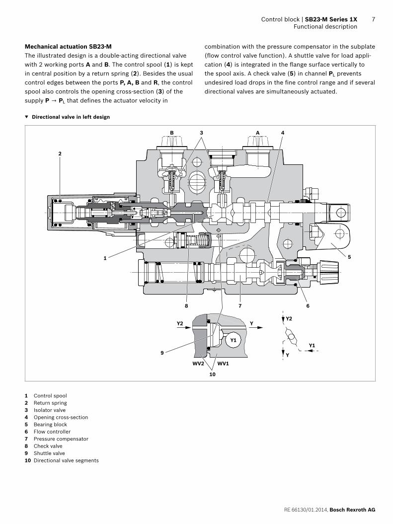
Mechanical actuation SB23-MThe illustrated design is a double-acting directional valve with 2 working ports A and B. The control spool (1) is kept in central position by a return spring (2). Besides the usual control edges between the ports P, A, B and R, the control spool also controls the opening cross-section (3) of the supply P → PL that defines the actuator velocity in
combination with the pressure compensator in the subplate (flow control valve function). A shuttle valve for load appli-cation (4) is integrated in the flange surface vertically to the spool axis. A check valve (5) in channel PL prevents undesired load drops in the fine control range and if several directional valves are simultaneously actuated.
▼ Directional valve in left design
B A
Y2Y2
Y1
Y
Y
WV2 WV1
Y1
2
43
1
8 7 6
5
9
10
1 Control spool2 Return spring3 Isolator valve4 Opening cross-section5 Bearing block6 Flow controller7 Pressure compensator8 Check valve9 Shuttle valve10 Directional valve segments
Bosch Rexroth AG, RE 66130/01.2014
8 SB23-M Series 1X | Control blockFunctional description
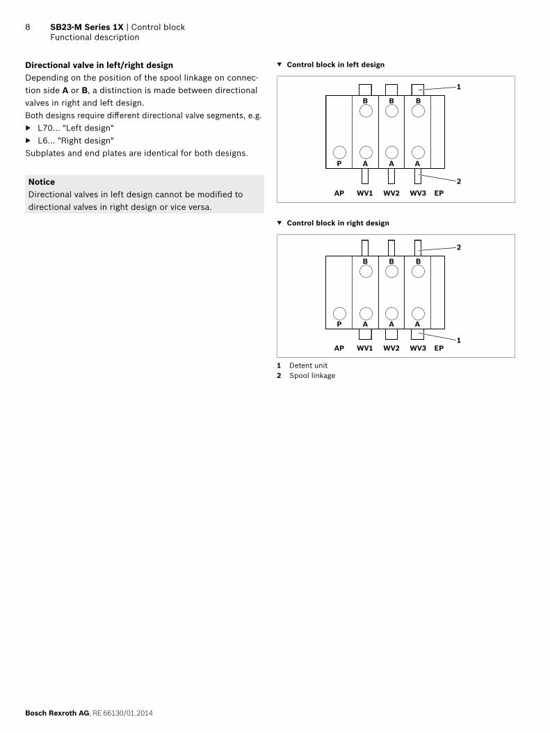
Directional valve in left/right designDepending on the position of the spool linkage on connec-tion side A or B, a distinction is made between directional valves in right and left design.Both designs require different directional valve segments, e.g.
▶ L70... "Left design" ▶ L6... "Right design"
Subplates and end plates are identical for both designs.
NoticeDirectional valves in left design cannot be modified to directional valves in right design or vice versa.
▼ Control block in left design
B B B
A A A
1
2
P
AP WV1 WV2 EPWV3
▼ Control block in right design
B B B
A A A
1
2
P
AP WV1 WV2 EPWV3
1 Detent unit2 Spool linkage
RE 66130/01.2014, Bosch Rexroth AG
Control block | SB23-M Series 1X Functional description
9
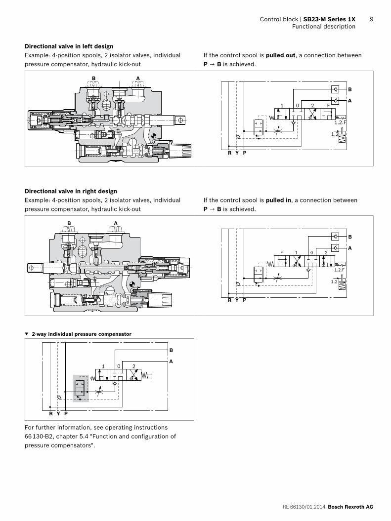
Directional valve in left designExample: 4-position spools, 2 isolator valves, individual pressure compensator, hydraulic kick-out
If the control spool is pulled out, a connection between P → B is achieved.
B A
Y PR
B
A
1.2
1.2.F
1 0 2 F
Directional valve in right designExample: 4-position spools, 2 isolator valves, individual pressure compensator, hydraulic kick-out
If the control spool is pulled in, a connection between P → B is achieved.
B A
Y PR
1.2
1.2.F
1 0 2F
B
A
▼ 2-way individual pressure compensator
Y PR
B
A1 0 2
For further information, see operating instructions 66 130-B2, chapter 5.4 "Function and configuration of pressure compensators".
Bosch Rexroth AG, RE 66130/01.2014
10 SB23-M Series 1X | Control blockFunctional description
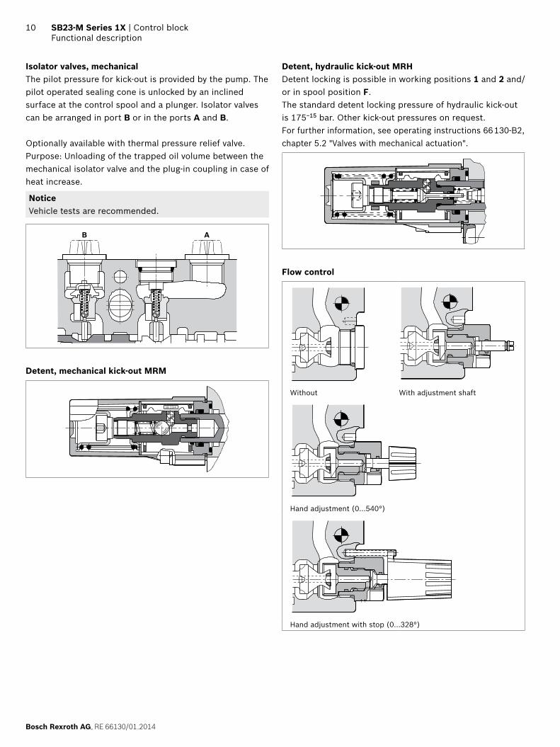
Isolator valves, mechanicalThe pilot pressure for kick-out is provided by the pump. The pilot operated sealing cone is unlocked by an inclined surface at the control spool and a plunger. Isolator valves can be arranged in port B or in the ports A and B.
Optionally available with thermal pressure relief valve.Purpose: Unloading of the trapped oil volume between the mechanical isolator valve and the plug-in coupling in case of heat increase.
NoticeVehicle tests are recommended.
B A
Detent, mechanical kick-out MRM
SB 23/4
Detent, hydraulic kick-out MRHDetent locking is possible in working positions 1 and 2 and/or in spool position F. The standard detent locking pressure of hydraulic kick-out is 175−15 bar. Other kick-out pressures on request.For further information, see operating instructions 66 130-B2, chapter 5.2 "Valves with mechanical actuation".
Flow control
Without With adjustment shaft
Hand adjustment (0...540°)
Hand adjustment with stop (0...328°)
RE 66130/01.2014, Bosch Rexroth AG
Control block | SB23-M Series 1X Technical data
11
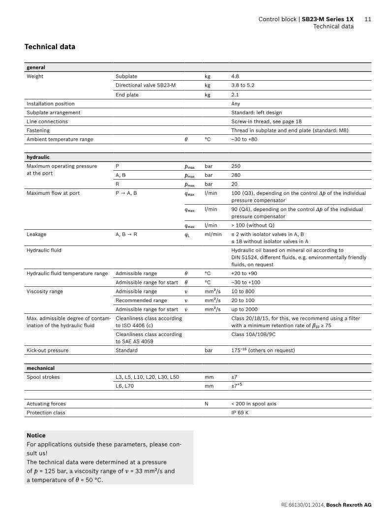
Technical data
general
Weight Subplate kg 4.8
Directional valve SB23-M kg 3.8 to 5.2
End plate kg 2.1
Installation position Any
Subplate arrangement Standard: left design
Line connections Screw-in thread, see page 18
Fastening Thread in subplate and end plate (standard: M8)
Ambient temperature range θ °C –30 to +80
hydraulic
Maximum operating pressure at the port
P pmax bar 250
A, B pmax bar 280
R pmax bar 20
Maximum flow at port P → A, B qmax l/min 100 (Q3), depending on the control Δp of the individual pressure compensator
qmax l/min 90 (Q4), depending on the control Δp of the individual pressure compensator
qmax l/min > 100 (without Q)
Leakage A, B → R qL ml/min ≦ 2 with isolator valves in A, B≦ 18 without isolator valves in A
Hydraulic fluid Hydraulic oil based on mineral oil according to DIN 51524, different fluids, e.g. environmentally friendly fluids, on request
Hydraulic fluid temperature range Admissible range θ °C +20 to +90
Admissible range for start θ °C –30 to +100
Viscosity range Admissible range ν mm²/s 10 to 800
Recommended range ν mm²/s 20 to 100
Admissible range for start ν mm²/s up to 2000
Max. admissible degree of contam-ination of the hydraulic fluid
Cleanliness class according to ISO 4406 (c)
Class 20/18/15, for this, we recommend using a filter with a minimum retention rate of β10 ≥ 75
Cleanliness class according to SAE AS 4059
Class 10A/10B/9C
Kick-out pressure Standard bar 175−15 (others on request)
mechanical
Spool strokes L3, L5, L10, L20, L30, L50 mm ±7
L6, L70 mm ±7+5
Actuating forces N < 200 in spool axis
Protection class IP 69 K
NoticeFor applications outside these parameters, please con-sult us!The technical data were determined at a pressure of p = 125 bar, a viscosity range of ν = 33 mm2/s and a temperature of θ = 50 °C.
Bosch Rexroth AG, RE 66130/01.2014
12 SB23-M Series 1X | Control blockType key
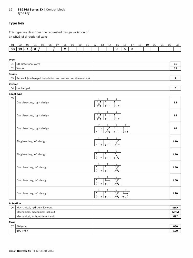
Type key
This type key describes the requested design variation of an SB23-M directional valve.
01 02 03 04 05 06 07 08 09 10 11 12 13 14 15 16 17 18 19 20 21 22 23
SB 23 1 0 M 3 5 0
Type01 SB directional valve SB
02 Version 23
Series03 Series 1 (unchanged installation and connection dimensions) 1
Version04 Unchanged 0
Spool type05
Double-acting, right design1 0 2
L3
Double-acting, right design1 0 2
L5
Double-acting, right designF 1 0 2
L6
Single-acting, left design1 0 2
L10
Single-acting, left design1 0 2
L20
Double-acting, left design1 0 2
L30
Double-acting, left design1 0 2
L50
Double-acting, left designF1 0 2
L70
Actuation06 Mechanical, hydraulic kick-out MRH
Mechanical, mechanical kick-out MRM
Mechanical, without detent unit MEA
Flow07 80 l/min 080
100 l/min 100
RE 66130/01.2014, Bosch Rexroth AG
Control block | SB23-M Series 1X Type key
13
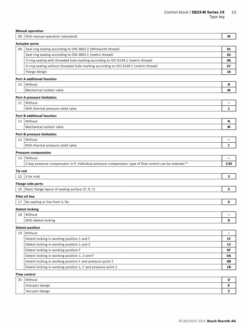
Manual operation08 With manual operation (standard) M
Actuator ports09 Seal ring sealing according to DIN 3852-2 (Whitworth thread) 01
Seal ring sealing according to DIN 3852-1 (metric thread) 02
O-ring sealing with threaded hole marking according to ISO 6149-1 (metric thread) 06
O-ring sealing without threaded hole marking according to ISO 6149-1 (metric thread) 07
Flange design 16
Port A additional function10 Without N
Mechanical isolator valve M
Port A pressure limitation11 Without –
With thermal pressure relief valve 1
Port B additional function12 Without N
Mechanical isolator valve M
Port B pressure limitation13 Without –
With thermal pressure relief valve 1
Pressure compensator14 Without –
2-way pressure compensator in P, individual pressure compensator, type of flow control can be selected 1) C30
Tie rod15 3 tie rods 3
Flange side ports16 Basic flange layout of sealing surface (P, R, Y) 5
Pilot oil line17 No sealing or line from X, Rx 0
Detent locking18 Without –
With detent locking D
Detent position19 Without –
Detent locking in working position 1 and F 1F
Detent locking in working position 1 and 2 12
Detent locking in working position F 0F
Detent locking in working position 1, 2 and F 0A
Detent locking in working position F and pressure point 2 0B
Detent locking in working position 1, F and pressure point 2 1B
Flow control20 Without O
One-part design E
Two-part design Z
Bosch Rexroth AG, RE 66130/01.2014
14 SB23-M Series 1X | Control blockType key
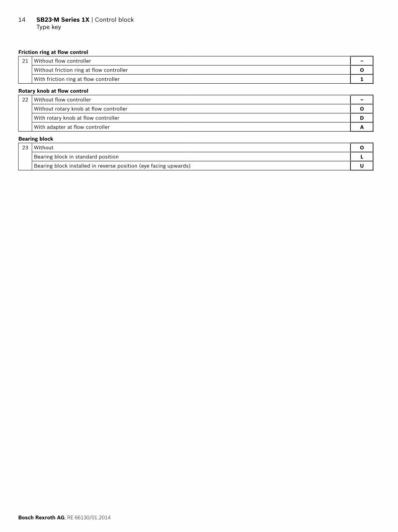
Friction ring at flow control21 Without flow controller –
Without friction ring at flow controller O
With friction ring at flow controller 1
Rotary knob at flow control22 Without flow controller –
Without rotary knob at flow controller O
With rotary knob at flow controller D
With adapter at flow controller A
Bearing block23 Without O
Bearing block in standard position L
Bearing block installed in reverse position (eye facing upwards) U
RE 66130/01.2014, Bosch Rexroth AG
Control block | SB23-M Series 1X Order overview
15
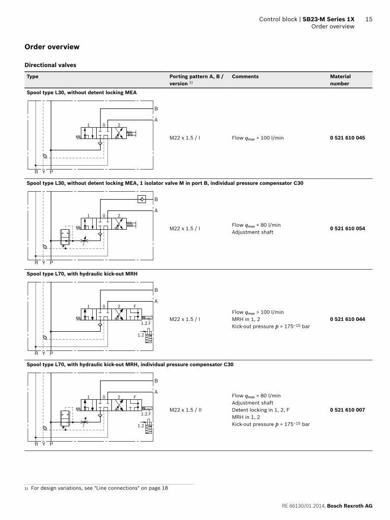
Order overview
Directional valves
Type Porting pattern A, B / version 1)
Comments Material number
Spool type L30, without detent locking MEA
Y PR
B
A1 0 2
M22 x 1.5 / I Flow qmax > 100 l/min 0 521 610 045
Spool type L30, without detent locking MEA, 1 isolator valve M in port B, individual pressure compensator C30
Y PR
B
A1 0 2
M22 x 1.5 / IFlow qmax = 80 l/minAdjustment shaft
0 521 610 054
Spool type L70, with hydraulic kick-out MRH
Y PR
B
A
1.2
1.2.F
1 0 2 F
M22 x 1.5 / IFlow qmax > 100 l/minMRH in 1, 2Kick-out pressure p = 175−15 bar
0 521 610 044
Spool type L70, with hydraulic kick-out MRH, individual pressure compensator C30
Y PR
B
A
1.2
1.2.F
1 0 2 F
M22 x 1.5 / II
Flow qmax = 80 l/minAdjustment shaftDetent locking in 1, 2, FMRH in 1, 2Kick-out pressure p = 175−15 bar
0 521 610 007
1) For design variations, see "Line connections" on page 18
Bosch Rexroth AG, RE 66130/01.2014
16 SB23-M Series 1X | Control blockOrder overview
Type Porting pattern A, B / version 1)
Comments Material number
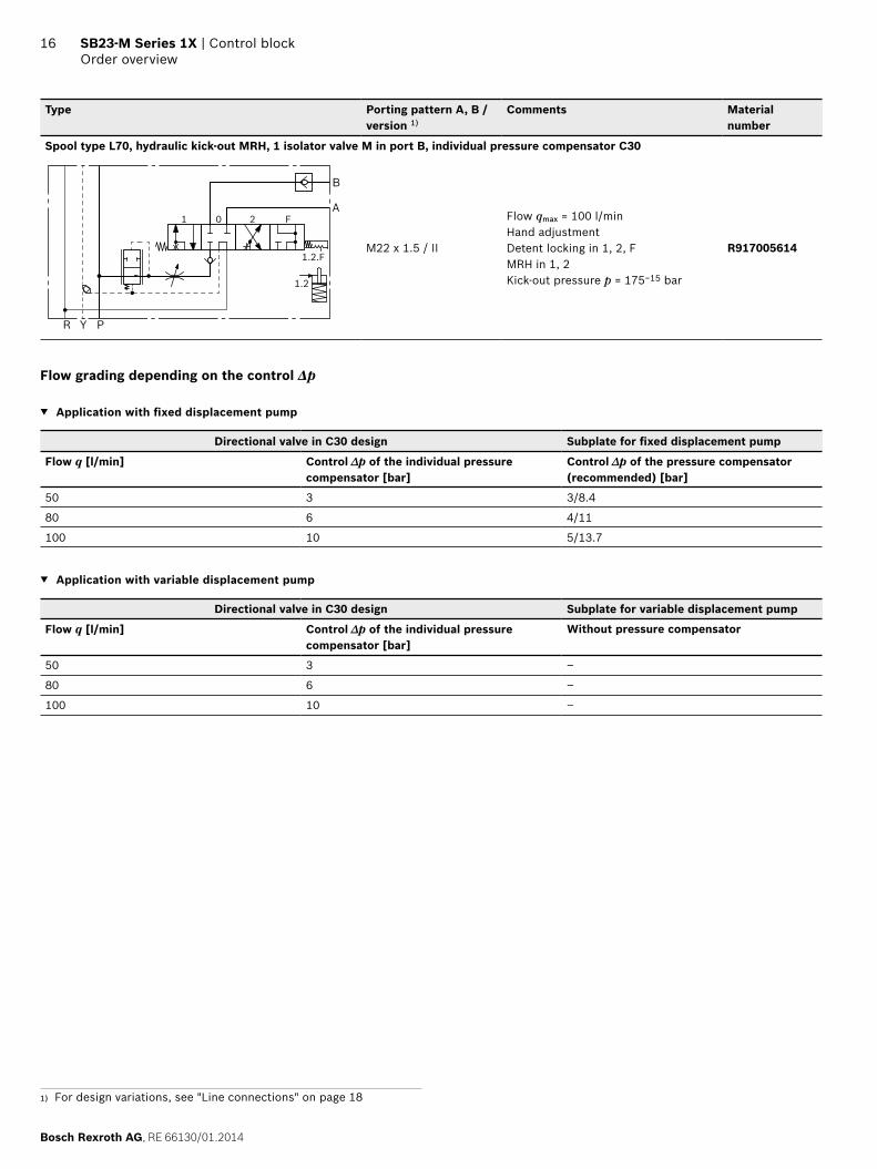
Spool type L70, hydraulic kick-out MRH, 1 isolator valve M in port B, individual pressure compensator C30
Y PR
B
A
1.2
1.2.F
1 0 2 F
M22 x 1.5 / II
Flow qmax = 100 l/minHand adjustmentDetent locking in 1, 2, FMRH in 1, 2Kick-out pressure p = 175−15 bar
R917005614
Flow grading depending on the control Δp
▼ Application with fixed displacement pump
Directional valve in C30 design Subplate for fixed displacement pump
Flow q [l/min] Control ∆p of the individual pressure compensator [bar]
Control ∆p of the pressure compensator (recommended) [bar]
50 3 3/8.4
80 6 4/11
100 10 5/13.7
▼ Application with variable displacement pump
Directional valve in C30 design Subplate for variable displacement pump
Flow q [l/min] Control ∆p of the individual pressure compensator [bar]
Without pressure compensator
50 3 –
80 6 –
100 10 –
1) For design variations, see "Line connections" on page 18
RE 66130/01.2014, Bosch Rexroth AG
Control block | SB23-M Series 1X Order overview
17
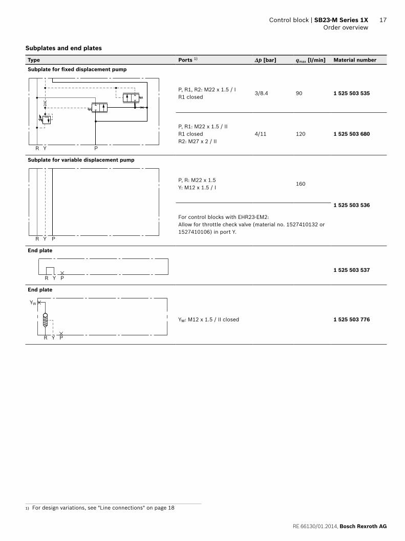
Subplates and end plates
Type Ports 1) Δp [bar] qmax [l/min] Material number
Subplate for fixed displacement pump
R Y P
P, R1, R2: M22 x 1.5 / IR1 closed
3/8.4 90 1 525 503 535
P, R1: M22 x 1.5 / IIR1 closedR2: M27 x 2 / II
4/11 120 1 525 503 680
Subplate for variable displacement pump
R Y P
P, R: M22 x 1.5Y: M12 x 1.5 / I
160
1 525 503 536
For control blocks with EHR23-EM2: Allow for throttle check valve (material no. 1527410132 or 1527410106) in port Y.
End plate
Y PR1 525 503 537
End plate
YW
Y PR
YW: M12 x 1.5 / II closed 1 525 503 776
1) For design variations, see "Line connections" on page 18
Bosch Rexroth AG, RE 66130/01.2014
18 SB23-M Series 1X | Control blockLine connections
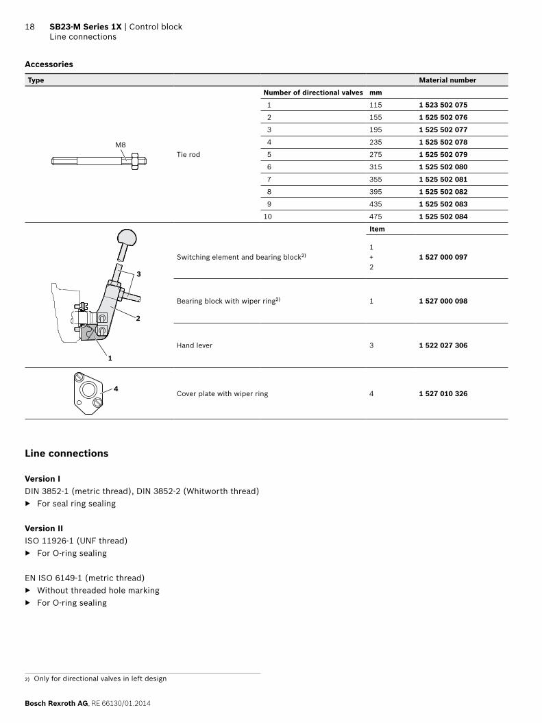
Accessories
Type Material number
M8Tie rod
Number of directional valves mm
1 115 1 523 502 075
2 155 1 525 502 076
3 195 1 525 502 077
4 235 1 525 502 078
5 275 1 525 502 079
6 315 1 525 502 080
7 355 1 525 502 081
8 395 1 525 502 082
9 435 1 525 502 083
10 475 1 525 502 084
3
2
1
Item
Switching element and bearing block2)1 + 2
1 527 000 097
Bearing block with wiper ring2) 1 1 527 000 098
Hand lever 3 1 522 027 306
4Cover plate with wiper ring 4 1 527 010 326
Line connections
Version IDIN 3852-1 (metric thread), DIN 3852-2 (Whitworth thread)
▶ For seal ring sealing
Version IIISO 11926-1 (UNF thread)
▶ For O-ring sealing
EN ISO 6149-1 (metric thread) ▶ Without threaded hole marking ▶ For O-ring sealing
2) Only for directional valves in left design
RE 66130/01.2014, Bosch Rexroth AG
Control block | SB23-M Series 1X Characteristic curves
19
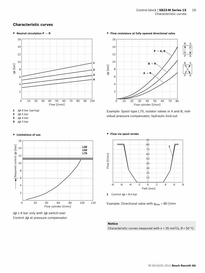
Characteristic curves
▼ Neutral circulation P → R
16
14
12
10
8
6
4
0
1
2
3
4
10 20 1009080706050
2
30 40Flow [l/min]
Δp [
bar]
1 Δp 6 bar (spring)2 Δp 5 bar3 Δp 4 bar4 Δp 3 bar
▼ Limitations of use
16
14
12
10
8
6
4
2
0 20 40 1201008060
L30L50L70
Flow cylinder [l/min]
Requ
ired
cont
rol Δ
p [b
ar]
Δp ≥ 6 bar only with Δp switch-overControl Δp at pressure compensator
▼ Flow resistance at fully opened directional valve
B A
P R
B
P → A, B
A → R
B → R
A
P R
16
14
12
10
8
6
4
2
0 2010 4030 8060 7050Flow cylinder [l/min]
Δp [
bar]
Example: Spool type L70, isolator valves in A and B, indi-vidual pressure compensator, hydraulic kick-out
▼ Flow via spool stroke
90
0 2-2-4-6-8 4 6 8
801
10
20
30
40
50
60
70
Path [mm]
Flow
[l/
min
]
1 Control Δp = 8.4 bar
Example: Directional valve with qmax = 80 l/min
NoticeCharacteristic curves measured with ν = 35 mm2/s, θ = 50 °C.
Bosch Rexroth AG, RE 66130/01.2014
20 SB23-M Series 1X | Control blockDimensions
Dimensions [mm]
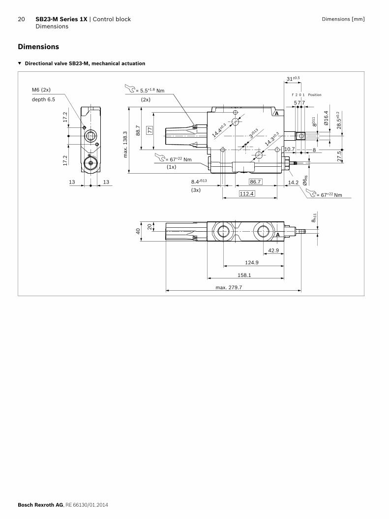
Dimensions
▼ Directional valve SB23-M, mechanical actuation
= 67+22 Nm
8.4J513
(3x)
(1x)
13
17.2
17.2
13 86.7 14.2
124.9
158.1
max. 279.7
= 5.5+1.8 NmM6 (2x)
depth 6.5 (2x)
40
20
112.4
Ø6 f
6
8 h11
27.5
28.5
±0.2
Ø16
.4
8D11
= 67+22 Nm
A
42.9
88.7
max
. 138
.3 3J513
14.3±0
.314.4±0
.3
31±0.5
5
F
8
77
2 Position
10.777
10
A
RE 66130/01.2014, Bosch Rexroth AG
Control block | SB23-M Series 1X Dimensions
21Dimensions [mm]
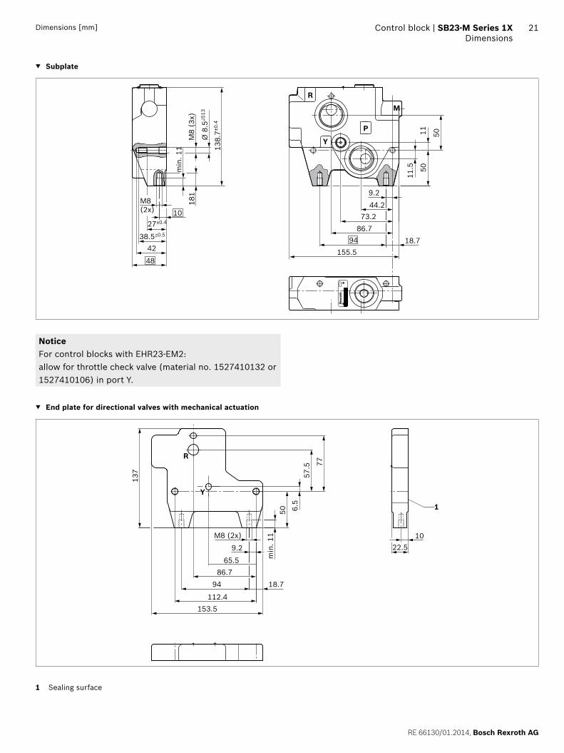
▼ Subplate
181
27±0.4
38.5±0.5
48
42
10M8(2x)
min
. 11 13
8.7±0
.4
Ø 8
.5JS
13
M8
(3x)
11.5
9.2
5011
R
Y
P
M
44.273.2
86.794 18.7
50
155.5
NoticeFor control blocks with EHR23-EM2: allow for throttle check valve (material no. 1527410132 or 1527410106) in port Y.
▼ End plate for directional valves with mechanical actuation
M8 (2x)
9.2
65.586.7
94 18.7
1022.5
112.4153.5
77
57.5
6.5
50m
in. 1
1
1
137
R
Y
1 Sealing surface
Bosch Rexroth AG, RE 66130/01.2014
22 SB23-M Series 1X | Control blockDimensions
Dimensions [mm]
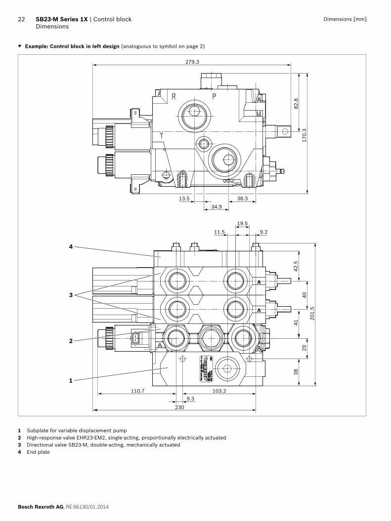
▼ Example: Control block in left design (analoguous to symbol on page 2)
279.3
38.3
19.5
9.211.5
A
A
13.534.9
42.5
170.
382
.8
9.3103.2110.7
1
230
4029
201.
5
3841
2
4
3
1 Subplate for variable displacement pump2 High-response valve EHR23-EM2, single-acting, proportionally electrically actuated3 Directional valve SB23-M, double-acting, mechanically actuated4 End plate
RE 66130/01.2014, Bosch Rexroth AG
Control block | SB23-M Series 1X Related documents
23
Related documents
Title Document number Document type
Directional valves SB23-LS for mobile applications 66130-B Operating instructions
Control block SB23, basic document 66133-01-R Repair instructions
Control valves SB23, assembly 66133-10-R Repair instructions
Control valves SB23-M, repair 66130-20-R Repair instructions
Bleeding directional valves MH 121 Commissioning information
Supplied installation drawing/hydraulic scheme Available from your machine or plant manufacturer
Quotation drawing
Hydraulic fluids on mineral oil basis 90220 Data sheet
Abbreviations
The following abbreviations are used in this documentation:
Abbreviation Meaning
EHR Electro-hydraulic lifting unit control
EHS1 Pilot operated electro-hydraulic actuating unit
LS Load sensing
OC Open center
SB23 Load-sensing control block in sandwich plate design
24
Bosch Rexroth AG, RE 66130/01.2014
Bosch Rexroth AGMobile ApplicationsRobert-Bosch-Straße 271701 Schwieberdingen, GermanyPhone +49 711 [email protected]
© This document, as well as the data, specifications and other information set forth in it, are the exclusive property of Bosch Rexroth AG. It may not be reproduced or given to third parties without its consent.. The data specified above only serve to describe the product. No statements concerning a certain condition or suitability for a certain application can be derived from our information. The information given does not release the user from the obligation of own judgment and verification. It must be remembered that our products are subject to a natural process of wear and aging.
SB23-M Series 1X | Control blockSpare parts
Spare parts
For spare parts, visit www.boschrexroth.com/spc
Contacts for accessories and spare partsAccessories and spare parts are available
▶ From the vehicle manufacturer (specialty retailer), ▶ From the system manufacturer, and ▶ From your Bosch Rexroth specialty retailer.
Please find Bosch Rexroth distribution partners at www.boschrexroth.com/adressen
If you have questions regarding spare parts, please contact your local Rexroth service or the service department of the control block manufacturer.
Bosch Rexroth AGRobert-Bosch-Straße 271701 SchwieberdingenGermanyPhone +49 (0) 711-811-84 81Fax +49 (0) 711-811-28 [email protected]


![Recent Advancement in Optical Fiber Sensing for ......detect impact damage in composite sandwich structures [18]. Pre-pump pulse Brillouin optical time-domain analysis (PPP-BOTDA)](https://static.fdocuments.us/doc/165x107/606bda2840e2c3244a39f391/recent-advancement-in-optical-fiber-sensing-for-detect-impact-damage-in.jpg)