Load Cube 2500KW Load Bank System Operator's … CUBE LOAD BANK SYSTEM TECHNICAL MANUAL (LBD Series)...
22
LOAD CUBE LOAD BANK SYSTEM TECHNICAL MANUAL (LBD Series) Customer: XXXXX Work Order: XXXXX-XX-XX Model: Load Cube Load Bank System March 2012 The information herein is the property of Simplex, Inc. and/or its subsidiaries. Without written permission, any copying, transmitting to others, and other use except that for which it is loaned, is prohibited. (File: LoadCube-120322.indd)
Transcript of Load Cube 2500KW Load Bank System Operator's … CUBE LOAD BANK SYSTEM TECHNICAL MANUAL (LBD Series)...
LOAD CUBE LOAD BANK SYSTEMTECHNICAL MANUAL
(LBD Series)
Customer: XXXXX
Work Order: XXXXX-XX-XX
Model: Load Cube Load Bank System
March 2012
The information herein is the property of Simplex, Inc. and/or its subsidiaries.Without written permission, any copying, transmitting to others, and other use
except that for which it is loaned, is prohibited.(File: LoadCube-120322.indd)

Simplex, Inc., 5300 Rising Moon Road, Springfi eld, IL 62711-6228 • 217-483-1600 • Fax 217-483-1616LoadCube-120322.indd • © 2012 Simplex, Inc. All Rights Reserved. • Printed in the USA. • www.simplexdirect.com
LOAD CUBE LOAD BANK SYSTEM MANUAL • page 1 of 21
®
Contents
DESCRIPTION .............................................................................. 2Control System ...................................................................... 4Cooling System ...................................................................... 4Load System ........................................................................... 4
PRIMARY INSPECTION ............................................................... 5
INSTALLATION ............................................................................. 5Location .................................................................................. 5
SETUP ........................................................................................... 6
LOCAL CONTROL ........................................................................ 7
REMOTE CONTROL ..................................................................... 8Manual Operation ................................................................... 8Numeric Load Application .................................................. 10Load Dump ........................................................................... 11Setup Screen ........................................................................ 11
FAILURE DETECTION ................................................................ 11Thermocouples .................................................................... 11
MAINTENANCE .......................................................................... 12Each Operation .................................................................... 12Every 50 Hours or 6 Months ............................................... 12Motor Lubrication ................................................................ 13
TROUBLESHOOTING ................................................................ 14Cooling Fan Motor Will Not Operate .................................. 14Cooling Failure Indicated .................................................... 14Metering System Does Not Operate Properly ................... 14Some Load Steps Cannot Be Energized ............................ 15
DRAWINGS AND PARTS LIST .................................................. 15
APPENDIX A - ABBREVIATIONS USED IN THIS MANUAL ..... 16
APPENDIX B - C A L C U L A T I O N S & FORMULAS ...................... 17
APPENDIX C - TORQUE VALUES ............................................. 20
Simplex, Inc., 5300 Rising Moon Road, Springfi eld, IL 62711-6228 • 217-483-1600 • Fax 217-483-1616LoadCube-120322.indd • © 2012 Simplex, Inc. All Rights Reserved. • Printed in the USA. • www.simplexdirect.com
LOAD CUBE LOAD BANK SYSTEM MANUAL • page 2 of 21
®
DESCRIPTION
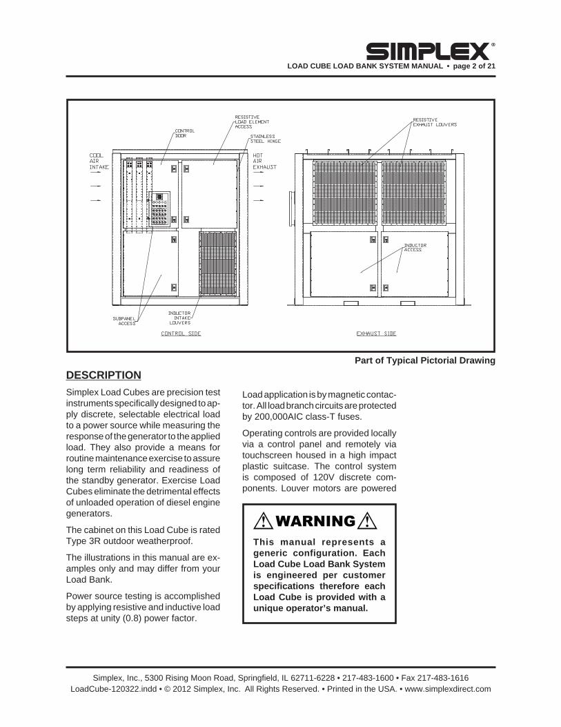
Simplex Load Cubes are precision test instruments specifi cally designed to ap-ply discrete, selectable electrical load to a power source while measuring the response of the generator to the applied load. They also provide a means for routine maintenance exercise to assure long term reliability and readiness of the standby generator. Exercise Load Cubes eliminate the detrimental effects of unloaded operation of diesel engine generators.
The cabinet on this Load Cube is rated Type 3R outdoor weatherproof.
The illustrations in this manual are ex-amples only and may differ from your Load Bank.
Power source testing is accomplished by applying resistive and inductive load steps at unity (0.8) power factor.
Part of Typical Pictorial Drawing
Load application is by magnetic contac-tor. All load branch circuits are protected by 200,000AIC class-T fuses.
Operating controls are provided locally via a control panel and remotely via touchscreen housed in a high impact plastic suitcase. The control system is composed of 120V discrete com-ponents. Louver motors are powered
This manual represents a generic configuration. Each Load Cube Load Bank System is engineered per customer specifi cations therefore each Load Cube is provided with a unique operator’s manual.

Simplex, Inc., 5300 Rising Moon Road, Springfi eld, IL 62711-6228 • 217-483-1600 • Fax 217-483-1616LoadCube-120322.indd • © 2012 Simplex, Inc. All Rights Reserved. • Printed in the USA. • www.simplexdirect.com
LOAD CUBE LOAD BANK SYSTEM MANUAL • page 3 of 21
®
via a 24VDC power supply located in the Load Cube. Common serviceable components include Control Fuses (CF Series), Load Application Fuses (F Series and XF Series), and Metering Fuses (MF Series). Lamps on the local control panel indicate the Load Cube operating status.
The Local Control Panel contains the following components:
1. Digital Meter
2. Normal Operation, Fan Failure, Over Temperature, Louvers Open and Louvers Closed indicator lamps
3. Mode Selector switch
4. Control Power switch
5. Load Dump Bypass switch
6. Fan Reversal switch
7. System Master Load switch
8. Resistive Master Load and load step switches
9. Inductive Master Load and load step switches
The “Normal Operation” lamp illumi-nates when Control Power is available and the Cooling System is operating properly.
This Load Cube is protected against cooling failures (loss of cooling air fl ow, high intake or exhaust air temperature which could damage the Load Cube or present a safety hazard to the opera-tor). When a cooling failure occurs the automatic safety features in the Control System immediately remove the load from the load source. The malfunction must be corrected and the system must be reset by turning the Load Cube “Off” then “On” before the load can be re-applied.

Simplex, Inc., 5300 Rising Moon Road, Springfi eld, IL 62711-6228 • 217-483-1600 • Fax 217-483-1616LoadCube-120322.indd • © 2012 Simplex, Inc. All Rights Reserved. • Printed in the USA. • www.simplexdirect.com
LOAD CUBE LOAD BANK SYSTEM MANUAL • page 4 of 21
®
The Load Cube consists of three prin-cipal systems:
1. Control System
2. Cooling System
3. Load System
CONTROL SYSTEM
The Control System allows the operator to apply a desired load to the test source and measure the response of the test source to the load. This system also contains the circuitry utilized to discon-nect the Load Cube from the test source in the event of cooling failures and/or improperly positioned operating controls.
Control Power (120V) is supplied inter-nally via the load source and the Control Power Transformer (T1) or externally via an appropriate source. Control power is applied to the coil of the Fan Motor Contactor (FMC1 and FMC3 or FMC2 and FMC4) when Fan Control Relay (FCR) contacts 7–4 close. When the operator places the Fan/Control Power switch (S1) in the “On” position the Fan Control Relay (FCR) energizes. The FCR contacts 7–4 close and energize the Fan Motor Contactors (FMC1 and FMC3 or FMC2 and FMC4). The FMC contacts close and complete the power path to the Fan Motors (MOT-A and MOT-B)
COOLING SYSTEM
The load elements in this Load Cube are cooled by a forced air system con-sisting of two (2) fan blades belt driven by a TEFC motor. The fan motor is energized by a Fan Motor Contactor (FMC) and protected by a Fan Circuit Breaker (FCB).
LOAD SYSTEM
The Load System consists of indepen-dently controlled resistive and/or reac-tive load elements specifi cally designed for Load Cube systems. They are pro-tected by 200,000AIC, 600VAC fuses.
Simplex Resistive Load Elements con-servatively operate at approximately half the maximum temperature rating of the alloy (1080°F vs. 1920°F). For example:
Alloy: FeCrAl
Ratings: 3333W@120V 4170W@139V
Connections: 120V wye (208V), 139V wye (240V, 3ø), 277V wye (480V, 3ø), 240 delta (240V, 3ø), or 480 delta (480V, 3ø).
See Parts Legend Drawing for specifi c elements used.
These elements are rigidly supported by high-temperature, ceramic-clad, stainless-steel supports. Element-to-element short circuits are virtually elimi-nated. The elements are assembled in discrete trays which are assembled in a vertical “stack”. Each tray is indepen-dently serviceable without disturbing adjacent trays.
Reactive Load Elements are iron-core, non-saturable, air gap calibrated and air cooled. Standard elements have a temperature sensor embedded in the windings to detect element overheating and are varnish coated. Epoxy coatings are available for severe environments.

Simplex, Inc., 5300 Rising Moon Road, Springfi eld, IL 62711-6228 • 217-483-1600 • Fax 217-483-1616LoadCube-120322.indd • © 2012 Simplex, Inc. All Rights Reserved. • Printed in the USA. • www.simplexdirect.com
LOAD CUBE LOAD BANK SYSTEM MANUAL • page 5 of 21
®
PRIMARY INSPECTION
Preventative visual inspections of the shipping crate and Load Cube is ad-vised. Physical or electrical problems due to handling and vibration may oc-cur. Never apply power to a Load Cube before performing this procedure. The following Nine Point/30 Minute Inspec-tion is recommended before installa-tion, as part of the 50 hour / 6 month maintenance schedule and whenever the Load Cube is relocated:
1. If crate shows any signs of damage examine the Load Cube in the cor-responding areas for signs of initial problems.
2. Check the entire outside of the cabinet for any visual damage which could cause internal electrical or mechanical problems due to reduced clearance.
3. Inspect all hinged panels and doors for smooth and safe operation, try all latches and knobs.
4. Rotate and push all switches through all positions to ensure smooth opera-tion.
5. Check cooling system by inspect-ing fan motor and blade. Check fan blades for stress fractures. Slowly rotate blade by hand and note clear-ance of blade tip through its rotation near the housing. Observe free rota-tion of motor shaft.
6. Inspect all relays, timers, and control modules by opening all accessible panels. Make sure all components are secure in their bases and safety bails are in place. Spot check electri-cal connections for tightness. If any loose connections are found inspect and tighten all remaining connec-tions.
7. Examine all accessible internal electrical components such as fuses, contactors and transformers. Check lugged wires at these components.
8. Inspect bottom of crate/enclosure for any components that may have jarred loose during shipment such as indicator light lenses, switch knobs, etc.
9. Visually inspect element chamber for foreign objects, broken ceramic insulators, mechanical damage.
INSTALLATION
LOCATION
This Load Cube is installed on a tandem axle fl atbed trailer. The load elements in this Load Cube are cooled by a forced air system which discharges through the side of the cabinet. This Load Cube will produce a large quantity of exhaust air. Location of the Load Cube is of prime importance and should be done by trained personnel. It is one of the most critical factors involved in safe opera-tion. The Load Cube must be positioned and installed according to large airfl ow requirements.
• There must be a minimum clearance of 25 feet on the discharge side and 6 feet on all other sides of the Load Cube.
• Never position the Load Cube so that any structure or object at any height is above the Load Cube.
If any problems are observed during Primary Inspection call the Simplex Service Manager at 217-483-1600 (24hrs.)
Simplex, Inc., 5300 Rising Moon Road, Springfi eld, IL 62711-6228 • 217-483-1600 • Fax 217-483-1616LoadCube-120322.indd • © 2012 Simplex, Inc. All Rights Reserved. • Printed in the USA. • www.simplexdirect.com
LOAD CUBE LOAD BANK SYSTEM MANUAL • page 6 of 21
®
• Always locate the Load Cube in a secure area accessible by trained personal only.
• Use forklift channels provided to lift and position the Load Cube.
• Never point the exhaust at a nearby surface or object which may be ad-versely affected by high temperature.
• Never operate the Load Cube in a confi ned space without regard for adequate intake of air and provision for exit of high temperature exhaust.
• Consider that the Load Cube and a nearby generator set may have to compete for cooling air.
• Never bounce hot exhaust air off nearby objects and allow it to recir-culate through the cooling system.
• Never operate the Load Cube in proximity to a sprinkler system.
Failure to properly install this Load Cube may result in substantial damage to or the destruction of the Load Cube, and adjacent equipment.
SETUP
Consult NEC for proper wire size for all connections unless stated within this manual or on a drawing.
1. Confi rm the test source is properly grounded and ground the Load Cube to its own independent ground.
2. Confi rm the Internal/External Circuit Breakers (FCB1 and FCB2) are in the “Off” position.
3. If External Fan/Control Power is desired connect the External Fan/Control Power Inlet to a 480V, 3ø, 60Hz, 30A maximum source.
4. If remote control is desired connect Receptacle 1 on the Load Bank to Receptacle 2 on the Remote Suit-case using the remote cable.
5. Confi rm all switches on the Local Control Panel are in the “Off” posi-tion.
6. Cable the load source to the Load Cube as shown.
7. Connect customer supplied Load Dump contacts to as shown.
Load is disengaged when contact is open.
8. Place the appropriate Fan/Control Power Circuit Breaker (FCB1 Inter-nal or FCB2 External) in the “On” position.
9. See digital meter manufacturer’s manual for meter operation.
10. Place the Mode Selector switch in the “Local” or “Remote” position.
11. Start-up generator set or bring other test source on line.
If external control power is used, energize the cooling fans before starting the generator for proper fan operation.
Do Not allow the Load Bank to operate unattended for extended periods.
Always remove all power from the load bus and all fan/control power before servicing the Load Bank. Never operate or service a Load Bank that is not properly connected to an earthground.

Simplex, Inc., 5300 Rising Moon Road, Springfi eld, IL 62711-6228 • 217-483-1600 • Fax 217-483-1616LoadCube-120322.indd • © 2012 Simplex, Inc. All Rights Reserved. • Printed in the USA. • www.simplexdirect.com
LOAD CUBE LOAD BANK SYSTEM MANUAL • page 7 of 21
®
LOCAL CONTROL
1. Verify the Fan Reversal switch is in the appropriate position.
2. Place the Fan/Control Power switch in the “On” position to open the louvers and energize the cooling fans.
The louvers will open before the fans energize.
3. Verify the louvers are open.
4. Verify the illumination of the “Normal Operation” lamp before proceeding.
5. Adjust source voltage.
6. Visually observe correct fan opera-tion and investigate any unusual fan related noises.
7. Check air intake for obstructions and confi rm positive air fl ow.
If the Load Bank airfl ow direction is reversed stop the fan motor immediately. After the motor has stopped completely change the position of the Fan Reversal switch and energize the fan mo-tor. Load Bank operation with the airfl ow direction reversed will damage the Load Bank.
8. Select the desired load steps by placing them in the “On” position.
9. Place the appropriate “Master Load” switch in the “On” position.
10. Place the “System Master Load” switch in the “On” position.
This simultaneously applies all of the load steps which are in the “On” position.
Trim is achieved by fl ipping the load steps “On” and “Off” while the “System Master Load” and the cor-responding “Master Load” switches are in the “On” position.
11. Adjust the load and monitor load source as needed.
Never operate or service a Load Bank that is not properly con-nected to an earthground.
If the Load Bank airfl ow direc-tion is reversed stop the fan motor immediately. After the motor has stopped completely change the position of the fan reversal switch and energize the fan motor. Load Bank opera-tion with the airfl ow direction reversed will damage the Load Bank.
Part of Typical Pictorial Drawing
Simplex, Inc., 5300 Rising Moon Road, Springfi eld, IL 62711-6228 • 217-483-1600 • Fax 217-483-1616LoadCube-120322.indd • © 2012 Simplex, Inc. All Rights Reserved. • Printed in the USA. • www.simplexdirect.com
LOAD CUBE LOAD BANK SYSTEM MANUAL • page 8 of 21
®
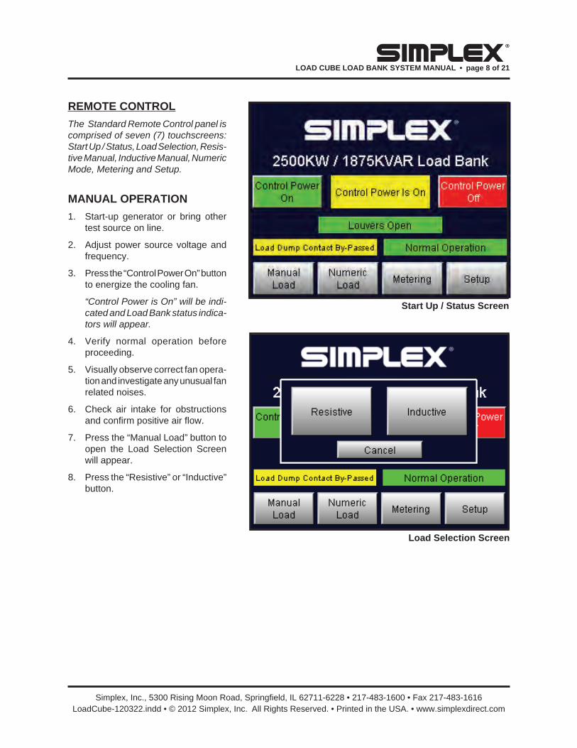
REMOTE CONTROL
The Standard Remote Control panel is comprised of seven (7) touchscreens: Start Up / Status, Load Selection, Resis-tive Manual, Inductive Manual, Numeric Mode, Metering and Setup.
MANUAL OPERATION
1. Start-up generator or bring other test source on line.
2. Adjust power source voltage and frequency.
3. Press the “Control Power On” button to energize the cooling fan.
“Control Power is On” will be indi-cated and Load Bank status indica-tors will appear.
4. Verify normal operation before proceeding.
5. Visually observe correct fan opera-tion and investigate any unusual fan related noises.
6. Check air intake for obstructions and confi rm positive air fl ow.
7. Press the “Manual Load” button to open the Load Selection Screen will appear.
8. Press the “Resistive” or “Inductive” button.
Load Selection Screen
Start Up / Status Screen

Simplex, Inc., 5300 Rising Moon Road, Springfi eld, IL 62711-6228 • 217-483-1600 • Fax 217-483-1616LoadCube-120322.indd • © 2012 Simplex, Inc. All Rights Reserved. • Printed in the USA. • www.simplexdirect.com
LOAD CUBE LOAD BANK SYSTEM MANUAL • page 9 of 21
®
9. Select the desired load steps by pressing the appropriate button.
10. Press the corresponding “Master Load” button.
11. If desired, press the “Status” button to go back to the Load Selection Screen and repeat load step selec-tion for Resistive or Inductive load.
12. Press the “System Master Load” button.
This simultaneously applies all of the load steps which are in the “On” position while the corresponding “Master Load” is in the “On” position.
Trim is achieved by turning the load steps “On” and “Off” while the corresponding “Master Load” and “System Master Load” are in the “On” position.
13. Adjust source voltage and load. Monitor as needed.
Shutdown
1 De-energize the load.
2. Run the cooling fan for 5 minutes to assure a thorough cool down of all load elements (optional).
3. Press the “Control Power Off” button on the Start Up / Status screen.
Resistive Load Step Screen
Inductive Load Step ScreenNever operate or service a Load Bank that is not properly con-nected to an earthground.

Simplex, Inc., 5300 Rising Moon Road, Springfi eld, IL 62711-6228 • 217-483-1600 • Fax 217-483-1616LoadCube-120322.indd • © 2012 Simplex, Inc. All Rights Reserved. • Printed in the USA. • www.simplexdirect.com
LOAD CUBE LOAD BANK SYSTEM MANUAL • page 10 of 21
®
Numeric Load Step Screen
NUMERIC LOAD APPLICATION
1. Start-up generator or bring other test source on line.
2. Adjust power source voltage and frequency.
3. Press the “Control Power On” button to energize the cooling fan.
“Control Power is On” will be indi-cated and Load Bank status indica-tors will appear.
4. Verify normal operation before proceeding.
5. Visually observe correct fan opera-tion and investigate any unusual fan related noises.
6. Check air intake for obstructions and confi rm positive air fl ow.
7. Press the “Numeric Load” button.
8. Press the “Enter KW Value to Apply” button and enter the desired value in the numeric pop-up screen.
9. Press the “Apply Numeric Load” button.
10. Adjust source voltage and load via the apply and remove buttons. Monitor as needed.
Shutdown
1 De-energize the load.
2. Run the cooling fan for 5 minutes to assure a thorough cool down of all load elements (optional).
3. Press the “Control Power Off” button on the Start Up / Status screen.
Start Up / Status Screen

Simplex, Inc., 5300 Rising Moon Road, Springfi eld, IL 62711-6228 • 217-483-1600 • Fax 217-483-1616LoadCube-120322.indd • © 2012 Simplex, Inc. All Rights Reserved. • Printed in the USA. • www.simplexdirect.com
LOAD CUBE LOAD BANK SYSTEM MANUAL • page 11 of 21
®
Setup Screen
LOAD DUMP
This Load Bank contains a Load Dump feature which de-energizes all applied load when customer supplied contacts open. Normally closed to run, they are rated at 2A @ 24VDC and should be wired to TB‘A’ 4–5. When these contacts open all applied load will be de-energized and the load section will be disabled. If desired, the customer may install automatic transfer switch contacts, a manual pushbutton or circuit breaker for this use.
The operator also has the option of bypassing these contacts and en-abling the load section by placing the “Load Dump Bypass” switch on the local control panel in the “Bypassed” position or pressing the “Load Dump Active Press To Bypass” button on the “Status” screen. This disables the load dump feature and illuminates the “Load Dump Bypass” lamp.
SETUP SCREEN
The Setup Screen is accessed via the “Setup” button on the Manual Load Ap-plication or Numeric Load Application. The intake and exhaust setpoints are factory set but may be modifi ed (see Failure Detection section below).
Metering Screen
FAILURE DETECTION
If a failure occurs the corresponding status indicator will be present and the load will be de-energized. Before reapplying a load, the failure must be corrected and the system must be reset by turning the Load Bank “Off” then “On”.
This is a permissive/energize-to-run circuit in which all safety sensors must energize their control relays on normal operation before load can be applied. This system will include the following components:
1. Thermocouples into Programmable Logic Controller (PLC) for intake and exhaust
2. Pressure Switch (PS)
THERMOCOUPLES
The thermocouples setpoints have been factory adjusted for precise Load Bank over temperature protection under normal operating conditions. Unusual operating conditions may require fi eld adjustment. The setpoints may be changed via the touch panel. Consult the Simplex Service Department (217-483-1600 24hrs) before changing the temperature switch setpoint.
Simplex, Inc., 5300 Rising Moon Road, Springfi eld, IL 62711-6228 • 217-483-1600 • Fax 217-483-1616LoadCube-120322.indd • © 2012 Simplex, Inc. All Rights Reserved. • Printed in the USA. • www.simplexdirect.com
LOAD CUBE LOAD BANK SYSTEM MANUAL • page 12 of 21
®
MAINTENANCE
The Load Bank has been designed to require minimum maintenance. All components have been chosen for a long, reliable life. Two basic intervals of maintenance are required: each op-eration and every 50 hours or 6 months (whichever comes fi rst).
EACH OPERATION
The air intake screens and louvers, fan and cooling chamber, and exhaust openings must be checked for any obstructions or foreign objects. Check fan blades for stress fractures. Due to the high volume of air circulated, paper and other items can be drawn into the air intakes. During Load Bank opera-tion insure that air is exiting from the exhaust vent.
The load branches should be checked for blown fuses or opened load resistors. To check the fuses or load resistors, operate the Load Bank from a balanced 3-phase source and check the three line currents. The three current read-ings should be essentially the same. If a sizeable difference is noted one or more load fuses or load resistors may have malfunctioned.
EVERY 50 HOURS OR 6 MONTHS
Check the tightness of the electrical connections. The expansion and con-traction caused by Load Bank operation may result in loose connections. The vibrations caused by the cooling fan may also loosen electrical connections. If the Load Bank is transported “over the road”, the electrical connections should be checked for tightness at a shorter-than-normal time interval. See “Primary Inspection”.
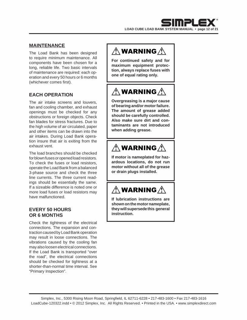
Overgreasing is a major cause of bearing and/or motor failure. The amount of grease added should be carefully controlled. Also make sure dirt and con-taminants are not introduced when adding grease.
If motor is nameplated for haz-ardous locations, do not run motor without all of the grease or drain plugs installed.
If lubrication instructions are shown on the motor nameplate, they will supersede this general instruction.
For continued safety and for maximum equipment protec-tion, always replace fuses with one of equal rating only.

Simplex, Inc., 5300 Rising Moon Road, Springfi eld, IL 62711-6228 • 217-483-1600 • Fax 217-483-1616LoadCube-120322.indd • © 2012 Simplex, Inc. All Rights Reserved. • Printed in the USA. • www.simplexdirect.com
LOAD CUBE LOAD BANK SYSTEM MANUAL • page 13 of 21
®
MOTOR LUBRICATION
Motors are properly lubricated at the time of manufacture. It is not necessary to lubricate at the time of installa-tion unless the motor has been in storage for a period of 12 months or longer (refer to lubri-cation procedure that follows).
Inspect the fan motor supplied with your Load Bank for grease fi ttings. If the motor contains grease fi ttings you must lubricate the motor. If lubrication instructions are shown on the mo-tor nameplate, they will supersede this general instruction. Belt driven cooling fans have bearings which should be lubri-cated. Bearings should be lubricated every 50 hours of operation or 6 months whichever comes fi rst.
Lubrication Procedure
1. Stop motor. Disconnect and lock out of service.
2. Remove contaminants from grease inlet area.
3. Remove fi ller and drain plugs.
4. Check fi ller and drain holes for block-age and clean as necessary.
5. Add proper type and amount of grease. See the Relubrication Time Intervals table for service schedule and Relubrication Amounts table for volume of grease required.
6. Wipe off excess grease and replace fi ller and drain plugs.
RELUBRICATION AMOUNTSfor motors with regreasing provisions.
NEMA Volume Frame Size cu. in. (fl uid oz.)
140 .25 (.14)
180 .50 (.28)
210 .75 (.42)
250 1.00 (.55)
280 1.25 (.69)
320 1.50 (.83)
360 1.75 (.97)
400 2.25 (1.2)
440 2.75 (1.5)
500 3.00 (1.7)
RELUBRICATION TIME INTERVALfor motors with regreasing provisions.
NEMA Frame Size
140 – 180 210 – 360 400 – 510
1800 RPM Over 1800 1800 RPM Over 1800 1800 RPM Over 1800 and less RPM and less RPM and less RPM
Standard 3 yrs. 8 mo. 2 yrs. 8 mo. 1 yr. 3 mo.
Severe 1 yr. 3 mo. 1 yr. 3 mo. 6 mo. 1 mo.
Seasonal See Note 2.
Standard: Up to 16 hours of operation per day, indoors, 100°F maximum ambient.
Severe: Greater than 16 hours of operation per day. Continuous operation under high ambient temperatures (100° to 150°F) and/or any of the following: dirty, moist loca-tions, high vibration (above NEMA standards), heavy shock loading, or where shaft extension end is hot.
Seasonal: The motor remains idle for a period of 6 months or more.
Note:
1. For motors nameplated as “belted duty only” divide the above intervals by 3.
2. Lubricate at the beginning of the season. Then follow service schedule above.
7. Motor is ready for operation.
Warning: If motor is nameplated for hazardous locations, do not run mo-tor without all of the grease or drain plugs installed.

Simplex, Inc., 5300 Rising Moon Road, Springfi eld, IL 62711-6228 • 217-483-1600 • Fax 217-483-1616LoadCube-120322.indd • © 2012 Simplex, Inc. All Rights Reserved. • Printed in the USA. • www.simplexdirect.com
LOAD CUBE LOAD BANK SYSTEM MANUAL • page 14 of 21
®
Grease Type
Unless stated otherwise on the motor nameplate, the motors on this Load Bank are pregreased with a polyurea mineral oil NGLI grade 2 type grease. Some compatible brands of polyurea mineral base type grease are:
• Chevron SRI #2
• Rykon Premium #2
• Exxon Polyrex EM
• Texaco Polystar RB
TROUBLESHOOTING
This section is designed to aid the electrical technician in basic Load Bank system troubleshooting. All of the prob-lems listed can be verifi ed with a basic test meter and/or continuity tester. For safety reasons, when troubleshooting Load Bank systems always remove all test source power, fan/control power, anti-condensation heater power, etc.
COOLING FAN MOTOR WILL NOT OPERATE
1. Inoperative Fan Circuit Breaker (FCB)
2. Fan/Control Power not available/incorrect
3. Inoperative Fan Motor (MOT)
4. Fan Motor Contactor (FMC) de-energized
5. Restriction of air (intake or ex-haust)
When troubleshooting Load Bank systems always remove all test source power, fan/con-trol power, anti-condensation heater power, etc.
COOLING FAILURE INDICATED
Exhaust temp above EXTS setpoint:
1. Over temperature sensor failure
2. Fan failure
3. Air restriction (intake or exhaust)
4. Overvoltage condition present
Exhaust temp below EXTS setpoint:
1. Restriction of air (intake or exhaust)
2. Fan pressure switch inoperative
3. Overtemperature sensor failure
METERING SYSTEM DOES NOT OPERATE PROPERLY
1. Meter voltage switch failure
2. Improper positioning of meter volt-age selector switch
3. Current transformer or current transformer wiring failure
4. Test meter failure
5. Meter fuses open

Simplex, Inc., 5300 Rising Moon Road, Springfi eld, IL 62711-6228 • 217-483-1600 • Fax 217-483-1616LoadCube-120322.indd • © 2012 Simplex, Inc. All Rights Reserved. • Printed in the USA. • www.simplexdirect.com
LOAD CUBE LOAD BANK SYSTEM MANUAL • page 15 of 21
®
SOME LOAD STEPS CANNOT BE ENERGIZED
1. Open load step resistor(s)
2. Inoperative load step relays
3. Inoperative load step contactors
4. Open load step fuses
DRAWINGS AND PARTS LISTThe drawings included in this manual are the most accurate source of part numbers for your Load Bank. When ordering replacement parts for Simplex Load Banks, always consult the Parts Drawing. When contacting the Simplex Service Department always have your work order and drawing number ready for reference. The Load Bank Specifi ca-tions Sheet in the front of this manual lists all of the drawings included in this manual. The Work Order Number and the Drawing Numbers are also located on each drawing legend. A typical draw-ing legend and parts list is illustrated at right.
Simplex, Inc., 5300 Rising Moon Road, Springfi eld, IL 62711-6228 • 217-483-1600 • Fax 217-483-1616LoadCube-120322.indd • © 2012 Simplex, Inc. All Rights Reserved. • Printed in the USA. • www.simplexdirect.com
LOAD CUBE LOAD BANK SYSTEM MANUAL • page 16 of 21
®
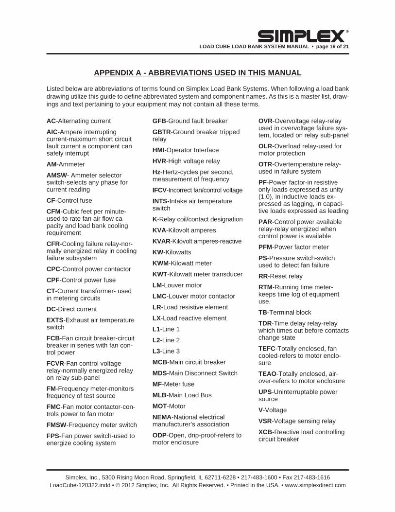
APPENDIX A - ABBREVIATIONS USED IN THIS MANUAL
Listed below are abbreviations of terms found on Simplex Load Bank Systems. When following a load bank drawing utilize this guide to defi ne abbreviated system and component names. As this is a master list, draw-ings and text pertaining to your equipment may not contain all these terms.
AC-Alternating current
AIC-Ampere interrupting current-maximum short circuit fault current a component can safely interrupt
AM-Ammeter
AMSW- Ammeter selector switch-selects any phase for current reading
CF-Control fuse
CFM-Cubic feet per minute-used to rate fan air fl ow ca-pacity and load bank cooling requirement
CFR-Cooling failure relay-nor-mally energized relay in cooling failure subsystem
CPC-Control power contactor
CPF-Control power fuse
CT-Current transformer- used in metering circuits
DC-Direct current
EXTS -Exhaust air temperature switch
FCB-Fan circuit breaker-circuit breaker in series with fan con-trol power
FCVR-Fan control voltage relay-normally energized relay on relay sub-panel
FM -Frequency meter-monitors frequency of test source
FMC -Fan motor contactor-con-trols power to fan motor
FMSW-Frequency meter switch
FPS -Fan power switch-used to energize cooling system
GFB -Ground fault breaker
GBTR -Ground breaker tripped relay
HMI-Operator Interface
HVR-High voltage relay
Hz -Hertz-cycles per second, measurement of frequency
IFCV -Incorrect fan/control voltage
INTS-Intake air temperature switch
K-Relay coil/contact designation
KVA-Kilovolt amperes
KVAR-Kilovolt amperes-reactive
KW-Kilowatts
KWM -Kilowatt meter
KWT-Kilowatt meter transducer
LM-Louver motor
LMC -Louver motor contactor
LR-Load resistive element
LX -Load reactive element
L1 -Line 1
L2 -Line 2
L3 -Line 3
MCB -Main circuit breaker
MDS -Main Disconnect Switch
MF -Meter fuse
MLB-Main Load Bus
MOT-Motor
NEMA-National electrical manufacturer’s association
ODP-Open, drip-proof-refers to motor enclosure
OVR-Overvoltage relay-relay used in overvoltage failure sys-tem, located on relay sub-panel
OLR-Overload relay-used for motor protection
OTR-Overtemperature relay- used in failure system
PF -Power factor-in resistive only loads expressed as unity (1.0), in inductive loads ex-pressed as lagging, in capaci-tive loads expressed as leading
PAR -Control power available relay-relay energized when control power is available
PFM-Power factor meter
PS -Pressure switch-switch used to detect fan failure
RR-Reset relay
RTM -Running time meter-keeps time log of equipment use.
TB-Terminal block
TDR-Time delay relay-relay which times out before contacts change state
TEFC -Totally enclosed, fan cooled-refers to motor enclo-sure
TEAO -Totally enclosed, air-over-refers to motor enclosure
UPS-Uninterruptable power source
V -Voltage
VSR -Voltage sensing relay
XCB -Reactive load controlling circuit breaker

Simplex, Inc., 5300 Rising Moon Road, Springfi eld, IL 62711-6228 • 217-483-1600 • Fax 217-483-1616LoadCube-120322.indd • © 2012 Simplex, Inc. All Rights Reserved. • Printed in the USA. • www.simplexdirect.com
LOAD CUBE LOAD BANK SYSTEM MANUAL • page 17 of 21
®
APPENDIX B - C A L C U L A T I O N S & FORMULAS
The following calculations are used to determine the actual kilowatt load being applied by the Load Bank, when line voltages and currents are known (at 1.0 power factor).
3 Ph a s e
1. Read all three line currents and fi nd the average reading.
2. Read all three line-to-line voltages and fi nd the average reading.
3. Multiply the average current times the average voltage.
4. Multiply the answer of step #3 times the square root of 3 (1.732).
5. Divide the answer of step #4 by 1000. The answer is the actual kilowatts of load being applied by the Load Bank.
S i n g l e P h a s e
1. Determine the line current.
2. Determine the line-to-line voltage.
3. Multiply the line current times the line-to-line voltage.
4. Divide the answer of step #3 by 1000.
5. The answer of step #4 is the actual kilowatts being applied by the load bank.
EXAMPLES
Using line voltages and currents:
3 Phase
Current Readings Voltage Readings A1 = 249A V1-2 = 481V A2 = 250A V2-3 = 479V A3 = 254A V3-1 = 483V
Average Current = A1 + A2 + A3
3
= 2 4 9 + 2 5 0 + 2 5 4
3
= 251A
Average Voltage = V1-2 + V2-3 + V3-1
3
= 4 8 1 + 4 7 9 + 4 8 3
3
= 481V
Kilowatts = V o l t s x Amps x 1 . 7 3 2
1000
= 4 8 1 x 2 5 1 x 1 . 7 3 2
1000
= 209.1KW
Single Phase
Current Reading: 150A Voltage Reading: 240V
Kilowatts = V o l t s x Amps
1000
= 150 x 240
1000
= 36.1KW
Simplex, Inc., 5300 Rising Moon Road, Springfi eld, IL 62711-6228 • 217-483-1600 • Fax 217-483-1616LoadCube-120322.indd • © 2012 Simplex, Inc. All Rights Reserved. • Printed in the USA. • www.simplexdirect.com
LOAD CUBE LOAD BANK SYSTEM MANUAL • page 18 of 21
®
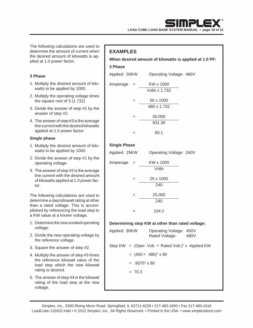
The following calculations are used to determine the amount of current when the desired amount of kilowatts is ap-plied at 1.0 power factor.
3 Ph a s e
1. Multiply the desired amount of kilo-watts to be applied by 1000.
2. Multiply the operating voltage times the square root of 3 (1.732)
3. Divide the answer of step #1 by the answer of step #2.
4. The answer of step #3 is the average line current with the desired kilowatts applied at 1.0 power factor.
S i n g l e p h a s e
1. Multiply the desired amount of kilo-watts to be applied by 1000.
2. Divide the answer of step #1 by the operating voltage.
3. The answer of step #2 is the average line current with the desired amount of kilowatts applied at 1.0 power fac-tor.
The following calculations are used to determine a step kilowatt rating at other than a rated voltage. This is accom-plished by referencing the load step to a KW value at a known voltage.
1. Determine the new unrated operating voltage.
2. Divide the new operating voltage by the reference voltage.
3. Square the answer of step #2.
4. Multiply the answer of step #3 times the reference kilowatt value of the load step which the new kilowatt rating is desired.
5. The answer of step #4 is the kilowatt rating of the load step at the new voltage.
EXAMPLES
When desired amount of kilowatts is applied at 1.0 PF:
3 Phase
Applied: 50KW Operating Voltage: 480V
Amperage = KW x 1000
Volts x 1.732
= 50 x 1000
480 x 1.732
= 50,000
831.36
= 60.1
Single Phase
Applied: 25KW Operating Voltage: 240V
Amperage = KW x 1000
Volts
= 25 x 1000
240
= 25,000
240
= 104.2
Determining step KW at other than rated voltage:
Applied: 80KW Operating Voltage: 450V Rated Voltage: 480V
Step KW = (Oper. Volt. ÷ Rated Volt.)2 x Applied KW
= (450 ÷ 480)2 x 80
= .93752 x 80
= 70.3

Simplex, Inc., 5300 Rising Moon Road, Springfi eld, IL 62711-6228 • 217-483-1600 • Fax 217-483-1616LoadCube-120322.indd • © 2012 Simplex, Inc. All Rights Reserved. • Printed in the USA. • www.simplexdirect.com
LOAD CUBE LOAD BANK SYSTEM MANUAL • page 19 of 21
®
FORMULAS
Alternating Current Direct Current
Kilowatts 1 phase Volts x Amps x PF * V o l t s x A m p s
1000 1000
3 phase 1.732 x Volts x Amps x PF*
1000
*Power Factor, expressed as decimal. (Resistive Load Bank PF is 1.0)
Amperes 1 phase KW x 1000 KW x 1000
(KW known) Volts x PF Volts
3 phase KW x 1000
1.732 x Volts x PF
KVA 1 phase V o l t s x Am p s
1000
3 phase 1.732 x Volts x Amps
1000
Amperes 1 phase KVA x 1000
(KVA known) Volts
3 phase KVA x 1000
1.732 x Volts
KVAR 1 phase Volts x Amps x 1 - PF2
1000
3 phase 1.732 x Volts x Amps x 1 -PF2
1000

Simplex, Inc., 5300 Rising Moon Road, Springfi eld, IL 62711-6228 • 217-483-1600 • Fax 217-483-1616LoadCube-120322.indd • © 2012 Simplex, Inc. All Rights Reserved. • Printed in the USA. • www.simplexdirect.com
LOAD CUBE LOAD BANK SYSTEM MANUAL • page 20 of 21
®
APPENDIX C - TORQUE VALUES
FAN BLADES
FAN TORQUE PART NO. BOLT SIZE FT LBS // IN LBS
13820000 SET SCREW 11.7 // 140
13820500 SET SCREW 11.7 // 140
13821000 SET SCREW 8.3 // 100
13822000 1/4 — 20 7.5 // 90
13823000 1/4 — 20 7.5 // 90
13824000 1/4 — 20 7.5 // 90
13825100 1/4 — 20 7.5 // 90
13826000 1/4 — 20 7.5 // 90
13827500 5/16” 13 // 156
13827600 5/16” 13 // 156
13828000 3/8” 24 // 288
MOTORS, BRACKETS, BUS BAR CONNECTIONS
BOLT/NUT TORQUE SIZE GRADE FT LBS // IN LBS
.250 (1/4-20) Grade 5, dry 8 // 96
.250 (1/4-20) Grade 2, dry 5.5 // 66
.312 (5/16) Grade 5, dry 17 // 204
.312 (5/16) Grade 2, dry 11 // 132
.375 (3/8) Grade 5, dry 30 // 360
.375 (3/8) Grade 2, dry 20 // 240
.437 (7/16) Grade 5, dry 50 // 600
.437 (7/16) Grade 2, dry 30 // 360
.500 (1/2) Grade 5, dry 75 // 900
.500 (1/2) Grade 2, dry 50 // 600
.562 (9/16) & up Grade 5, dry 110 // 1320
.562 (9/16) & up Grade 2, dry 70 // 840
CONTACTORS
See torque values on the front of the contactor.
ELEMENTS/TRAYS
TERM/NUT TORQUE SIZE INCH LBS
#6 Rod ends 4
#10 Element Conn. 20
1/4-20 High Voltage Contact Simplex
MAIN LOAD BLOCKS- ALL SIZES
WIRE TORQUE CONNECTION SIZE FT LBS // IN LBS
LOAD SIDE 4-14AWG 2.9 // 35
LINE SIDE 500MCM-4/0 31 // 375
3/0-4/0 20 // 240
2/0-6AWG 10 // 120
8AWG 3.3 // 40
CIRCUIT BREAKERS
WIRE TORQUE STYLE SIZE INCH LBS
Cutler-Hammer 14-10 AWG 20 1-Phase 8 AWG 25
6-4 AWG 27
3-1/0 AWG 45
Merlin Gerin 14-1/0 50 3-Phase
Simplex, Inc., 5300 Rising Moon Road, Springfi eld, IL 62711-6228 • 217-483-1600 • Fax 217-483-1616LoadCube-120322.indd • © 2012 Simplex, Inc. All Rights Reserved. • Printed in the USA. • www.simplexdirect.com
LOAD CUBE LOAD BANK SYSTEM MANUAL • page 21 of 21
®
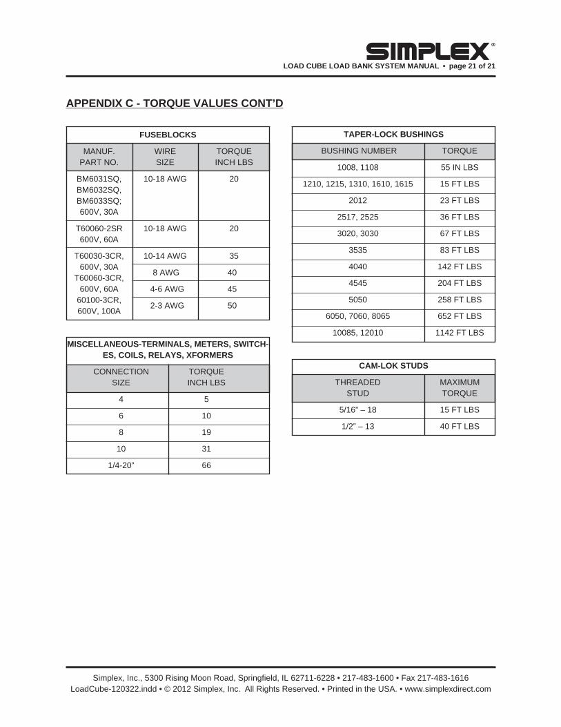
FUSEBLOCKS
MANUF. WIRE TORQUE PART NO. SIZE INCH LBS
BM6031SQ, 10-18 AWG 20 BM6032SQ, BM6033SQ; 600V, 30A
T60060-2SR 10-18 AWG 20 600V, 60A
T60030-3CR, 10-14 AWG 35 600V, 30A T60060-3CR, 600V, 60A 60100-3CR, 600V, 100A
MISCELLANEOUS-TERMINALS, METERS, SWITCH-ES, COILS, RELAYS, XFORMERS
CONNECTION TORQUE SIZE INCH LBS
4 5
6 10
8 19
10 31
1/4-20” 66
TAPER-LOCK BUSHINGS
BUSHING NUMBER TORQUE
1008, 1108 55 IN LBS
1210, 1215, 1310, 1610, 1615 15 FT LBS
2012 23 FT LBS
2517, 2525 36 FT LBS
3020, 3030 67 FT LBS
3535 83 FT LBS
4040 142 FT LBS
4545 204 FT LBS
5050 258 FT LBS
6050, 7060, 8065 652 FT LBS
10085, 12010 1142 FT LBS
CAM-LOK STUDS
THREADED MAXIMUM STUD TORQUE
5/16” – 18 15 FT LBS
1/2” – 13 40 FT LBS
APPENDIX C - TORQUE VALUES CONT’D
8 AWG 40
4-6 AWG 45
2-3 AWG 50