Load Alleviation on Wind Turbines using Camber Morphing ...
15
Load Alleviation on Wind Turbines using Camber Morphing Blade Tip Etana Ferede * and Farhan Gandhi † Rotorcraft, Adaptive, and Morphing Structures (RAMS) Lab Department of Mechanical, Aerospace, and Nuclear Engineering Rensselaer Polytechnic Institute, Troy, NY, 12180, USA This paper investigates the load alleviation capability of a camber morphing blade tip on multi megawatt scale HAWTs. A span-wise variation of camber at the outer blade region is proposed that blends seamlessly to the non-morphing part of the rotor blade. The NREL 5MW reference turbine is used as baseline design, where the outer 30% of the blade is linearly cambered with the maximum camber realized at the blade tip. The results obtained during simulations, following the IEC standard, indicate that the camber morphing blade tip is able to mitigate vibrational loads, such that reduction in fatigue loads range between 8%-37% for most wind turbine components. Furthermore, the controller is also capable of reducing ultimate loads due to extreme turbulence in the order of 30%-60%. Finally, a large reduction in peak-to-peak response, in the order of 43%-90%, is achieved for several turbine components under wind gust or extreme direction change. I. Introduction The Cost Of Energy (COE) is a key metric in the wind energy industry to evaluate the success of generating electricity from wind compared to other energy sources. Therefore, both the scientific community and the industry are continuously searching for ways to reduce the COE in order to make it competitive with already established methods for generating electricity. The cost of energy is reduced by increasing the Annual Energy Production (AEP). AEP is increased by expanding the rotor swept area in order to maximize energy capture from wind. As a result, the trend in wind energy industry is towards larger wind turbines, especially for offshore wind farms. Unfortunately, scaling of the existing wind turbine components increases the COE since AEP is proportional to the square of rotor radius while the cost of wind turbine components is proportional to the cubic of rotor radius. An alternative approach is to look at load alleviation methods allowing for increased rotor radius (hence larger AEP), while mitigating loads which reduces the cost growth rate of wind turbine components. The loads on wind turbine components can be reduced using active or passive control methods, applied over the whole blade span or distributed. Among the available load control methods, the Individual Pitch Control (IPC) is gaining more acceptance by the wind energy industry. 1 Another full span load control is the bend-twist coupled rotor blades 2 , where the structural properties of these blades is used to passively alleviate the loads on wind turbine components. However, these methods are limited in terms of bandwidth due to inertia, and non local blade response. Furthermore, fatigue concerns on pitch bearings limits the applicability of IPC for load alleviation. The distributed methods for load mitigation are attractive by providing higher bandwidth and control of local blade response, allowing further reduction in loads. Among distributed control methods, the use of flaps 3–6 and tabs 7–10 are extensively researched in the wind energy community. Unfortunately, wind turbine blades with flaps or tabs suffer from loss in aerodynamic performance and increased noise due to turbulent flow generation at the control surface edges. In the present study, active Camber Morphing Blade Tips (CMBT) are used to mitigate the vibratory loads on multi megawatt Horizontal Axis Wind Turbines (HAWTs). With a linear variation in camber from * Research scientist, Mechanical, Aerospace, and Nuclear Engineering, [email protected] † Professor, Mechanical, Aerospace, and Nuclear Engineering, AIAA Associate Fellow, [email protected] 1 of 15 American Institute of Aeronautics and Astronautics Downloaded by Farhan Gandhi on September 10, 2018 | http://arc.aiaa.org | DOI: 10.2514/6.2018-2020 2018 Wind Energy Symposium 8–12 January 2018, Kissimmee, Florida 10.2514/6.2018-2020 Copyright © 2018 by the American Institute of Aeronautics and Astronautics, Inc. All rights reserved. AIAA SciTech Forum
Transcript of Load Alleviation on Wind Turbines using Camber Morphing ...
Load Alleviation on Wind Turbines
using Camber Morphing Blade Tip
Etana Ferede ∗ and Farhan Gandhi †
Rotorcraft, Adaptive, and Morphing Structures (RAMS) Lab
Department of Mechanical, Aerospace, and Nuclear Engineering
Rensselaer Polytechnic Institute, Troy, NY, 12180, USA
This paper investigates the load alleviation capability of a camber morphing blade tipon multi megawatt scale HAWTs. A span-wise variation of camber at the outer bladeregion is proposed that blends seamlessly to the non-morphing part of the rotor blade.The NREL 5MW reference turbine is used as baseline design, where the outer 30% ofthe blade is linearly cambered with the maximum camber realized at the blade tip. Theresults obtained during simulations, following the IEC standard, indicate that the cambermorphing blade tip is able to mitigate vibrational loads, such that reduction in fatigue loadsrange between 8%-37% for most wind turbine components. Furthermore, the controller isalso capable of reducing ultimate loads due to extreme turbulence in the order of 30%-60%.Finally, a large reduction in peak-to-peak response, in the order of 43%-90%, is achieved forseveral turbine components under wind gust or extreme direction change.
I. Introduction
The Cost Of Energy (COE) is a key metric in the wind energy industry to evaluate the success ofgenerating electricity from wind compared to other energy sources. Therefore, both the scientific communityand the industry are continuously searching for ways to reduce the COE in order to make it competitivewith already established methods for generating electricity. The cost of energy is reduced by increasing theAnnual Energy Production (AEP). AEP is increased by expanding the rotor swept area in order to maximizeenergy capture from wind. As a result, the trend in wind energy industry is towards larger wind turbines,especially for offshore wind farms. Unfortunately, scaling of the existing wind turbine components increasesthe COE since AEP is proportional to the square of rotor radius while the cost of wind turbine componentsis proportional to the cubic of rotor radius. An alternative approach is to look at load alleviation methodsallowing for increased rotor radius (hence larger AEP), while mitigating loads which reduces the cost growthrate of wind turbine components.
The loads on wind turbine components can be reduced using active or passive control methods, appliedover the whole blade span or distributed. Among the available load control methods, the Individual PitchControl (IPC) is gaining more acceptance by the wind energy industry.1 Another full span load control is thebend-twist coupled rotor blades2 , where the structural properties of these blades is used to passively alleviatethe loads on wind turbine components. However, these methods are limited in terms of bandwidth due toinertia, and non local blade response. Furthermore, fatigue concerns on pitch bearings limits the applicabilityof IPC for load alleviation. The distributed methods for load mitigation are attractive by providing higherbandwidth and control of local blade response, allowing further reduction in loads. Among distributedcontrol methods, the use of flaps3–6 and tabs7–10 are extensively researched in the wind energy community.Unfortunately, wind turbine blades with flaps or tabs suffer from loss in aerodynamic performance andincreased noise due to turbulent flow generation at the control surface edges.
In the present study, active Camber Morphing Blade Tips (CMBT) are used to mitigate the vibratoryloads on multi megawatt Horizontal Axis Wind Turbines (HAWTs). With a linear variation in camber from
∗Research scientist, Mechanical, Aerospace, and Nuclear Engineering, [email protected]†Professor, Mechanical, Aerospace, and Nuclear Engineering, AIAA Associate Fellow, [email protected]
1 of 15
American Institute of Aeronautics and Astronautics
Dow
nloa
ded
by F
arha
n G
andh
i on
Sept
embe
r 10
, 201
8 | h
ttp://
arc.
aiaa
.org
| D
OI:
10.
2514
/6.2
018-
2020
2018 Wind Energy Symposium
8–12 January 2018, Kissimmee, Florida
10.2514/6.2018-2020
Copyright © 2018 by the American Institute of Aeronautics and Astronautics, Inc. All rights reserved.
AIAA SciTech Forum
maximum at the blade tip to zero at the inboard end of the active section, the CMBT can offer increasedaerodynamic efficiency and reduced noise, since the cambered blade section blends seamlessly with the non-morphing section of the blade and hence no turbulent flows are generated that adversely affects the rotorperformance. Load alleviation capability of the current method is evaluated using international certificationstandard within FAST,11 a state-of-the-art aero-servo-elastic simulation tool for wind turbine load analysis.
II. Concept
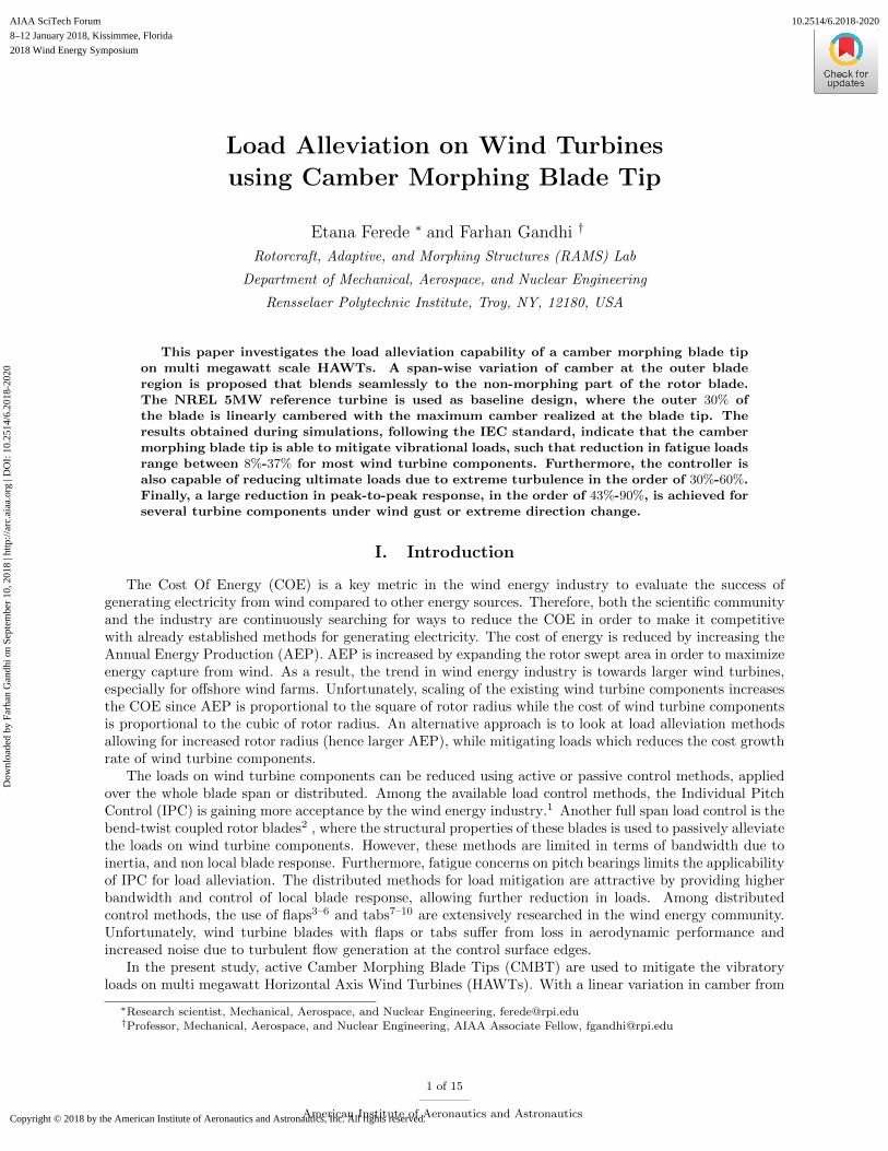
This paper investigates the load alleviation capability of Camber Morphing Blade Tip on multi megawattscale HAWTs. A span-wise variation of camber at the outer blade region is proposed that blends seamlesslyto the non-morphing part of the rotor blade, as shown in Figure 1. Looking at Figure 1, linear camber
Figure 1. Concept of camber morphing blade tip.
variation along the blade span is implemented where the magnitude of morphing angle θ is given by:
θ = εθtip, (1)
linearly increasing towards the blade tip for ε ∈ [0, 1], where θtip is the maximum morphing angle realizedat the blade tip. Finally, chord-wise section of the airfoil with actively changing camber is denoted by εc inFigure 1.
III. Turbine
The NREL 5MW12 reference turbine is used as the baseline turbine with the gross properties given inTable 1. The 5MW Machine is a pitch regulated turbine with a rotor diameter of 126m and a hub heightof 90m. The current study does not include the underwater support structure in the modeling process.The outer 30% of the blade, consisting of the airfoil shape NACA 60-618, is linearly cambered with themaximum camber realized at the blade tip. On the airfoil section, the percentage of the chord designated forcamber morphing is determined by performing a 2D analysis of an airfoil shape where the chord length ofthe trailing-edge camber section was varied parametrically. From the analysis, the NACA 60-618 airfoil with30% of its trailing edge cambered is selected on the basis of sufficient change in lift (∆cl) without significantincrease in drag (high ∆cl
∆cd) compared to the baseline airfoil. The change in airfoil shape is achieved by
modifying the camber line. A quadratic function is added to the camber line, such that:
∆yc =
0 if x < xs
(x− xs)2
Cftan θ, otherwise,
(2)
2 of 15
American Institute of Aeronautics and Astronautics
Dow
nloa
ded
by F
arha
n G
andh
i on
Sept
embe
r 10
, 201
8 | h
ttp://
arc.
aiaa
.org
| D
OI:
10.
2514
/6.2
018-
2020
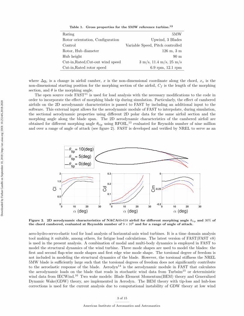
Table 1. Gross properties for the 5MW reference turbine.12
Rating 5MW
Rotor orientation, Configuration Upwind, 3 Blades
Control Variable Speed, Pitch controlled
Rotor, Hub diameter 126 m, 3 m
Hub height 90 m
Cut-in,Rated,Cut-out wind speed 3 m/s, 11.4 m/s, 25 m/s
Cut-in,Rated rotor speed 6.9 rpm, 12.1 rpm
where ∆yc is a change in airfoil camber, x is the non-dimensional coordinate along the chord, xs is thenon-dimensional starting position for the morphing section of the airfoil, Cf is the length of the morphingsection, and θ is the morphing angle.
The open source code FAST11 is used for load analysis with the necessary modifications to the code inorder to incorporate the effect of morphing blade tip during simulation. Particularly, the effect of camberedairfoils on the 2D aerodynamic characteristics is passed to FAST by including an additional input to thesoftware. This external input allows for the aerodynamic module of FAST to interpolate, during simulation,the sectional aerodynamic properties using different 2D polar data for the same airfoil section and themorphing angle along the blade span. The 2D aerodynamic characteristics of the cambered airfoil areobtained for different morphing angle θtip using RFOIL,13 evaluated for Reynolds number of nine millionand over a range of angle of attack (see figure 2). FAST is developed and verified by NREL to serve as an
θtip
= 10(deg)
θtip
= 5(deg)
θtip
= 0(deg)
α (deg)0 10 20 30
Cl
0
0.5
1
1.5
2
α (deg)0 10 20 30
Cd
0
0.1
0.2
0.3
α (deg)0 10 20 30
Cm
-0.5
-0.25
0
Figure 2. 2D aerodynamic characteristics of NACA60-618 airfoil for different morphing angle θtip and 30% ofthe chord cambered, evaluated at Reynolds number of 9 × 10⁶ and for a range of angle of attack.
aero-hydro-servo-elastic tool for load analysis of horizontal-axis wind turbines. It is a time domain analysistool making it suitable, among others, for fatigue load calculations. The latest version of FAST(FAST v8)is used in the present analysis. A combination of modal and multi-body dynamics is employed in FAST tomodel the structural dynamics of the wind turbine. Three mode shapes are used to model the blades: thefirst and second flap-wise mode shapes and first edge wise mode shape. The torsional degree of freedom isnot included in modeling the structural dynamics of the blade. However, the torsional stiffness the NREL5MW blade is sufficiently large such that the torsional degrees of freedom does not significantly contributeto the aeroelastic response of the blade. Aerodyn14 is the aerodynamic module in FAST that calculatesthe aerodynamic loads on the blade that reads in stochastic wind data from Turbsim15 or deterministicwind data from IECWind.16 Two wake models: Blade Element Momentum(BEM) theory and GeneralizedDynamic Wake(GDW) theory, are implemented in Aerodyn. The BEM theory with tip-loss and hub-losscorrections is used for the current analysis due to computational instability of GDW theory at low wind
3 of 15
American Institute of Aeronautics and Astronautics
Dow
nloa
ded
by F
arha
n G
andh
i on
Sept
embe
r 10
, 201
8 | h
ttp://
arc.
aiaa
.org
| D
OI:
10.
2514
/6.2
018-
2020
speeds. Finally, a quasi-steady analysis is carried out which excludes the effect of dynamic inflow andunsteady 2D aerodynamics from the present analysis.
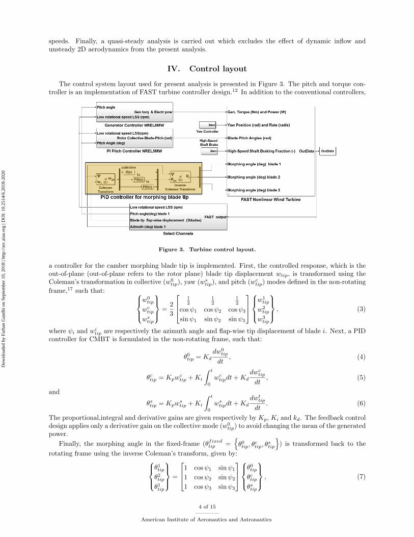
IV. Control layout
The control system layout used for present analysis is presented in Figure 3. The pitch and torque con-troller is an implementation of FAST turbine controller design.12 In addition to the conventional controllers,
Figure 3. Turbine control layout.
a controller for the camber morphing blade tip is implemented. First, the controlled response, which is theout-of-plane (out-of-plane refers to the rotor plane) blade tip displacement wtip, is transformed using theColeman’s transformation in collective (w0
tip), yaw (wstip), and pitch (wc
tip) modes defined in the non-rotating
frame,17 such that: w0
tip
wctip
wstip
=2
3
12
12
12
cosψ1 cosψ2 cosψ3
sinψ1 sinψ2 sinψ3
w1
tip
w2tip
w3tip
, (3)
where ψi and witip are respectively the azimuth angle and flap-wise tip displacement of blade i. Next, a PID
controller for CMBT is formulated in the non-rotating frame, such that:
θ0tip = Kd
dw0tip
dt, (4)
θctip = Kpwctip +Ki
∫ t
0
wctipdt+Kd
dwctip
dt, (5)
and
θstip = Kpwstip +Ki
∫ t
0
wstipdt+Kd
dwttip
dt. (6)
The proportional,integral and derivative gains are given respectively by Kp, Ki and kd. The feedback controldesign applies only a derivative gain on the collective mode (w0
tip) to avoid changing the mean of the generatedpower.
Finally, the morphing angle in the fixed-frame (θfixedtip =θ0tip, θ
ctip, θ
stip
) is transformed back to the
rotating frame using the inverse Coleman’s transform, given by:θ1tip
θ2tip
θ1tip
=
1 cosψ1 sinψ1
1 cosψ2 sinψ2
1 cosψ3 sinψ3
θ0tip
θctipθstip
, (7)
4 of 15
American Institute of Aeronautics and Astronautics
Dow
nloa
ded
by F
arha
n G
andh
i on
Sept
embe
r 10
, 201
8 | h
ttp://
arc.
aiaa
.org
| D
OI:
10.
2514
/6.2
018-
2020

where θi is the maximum morphing angle of blade i. The gains of the PID controller are tuned firstby analyzing the frequency content of flap-wise blade root bending moment and tower-top yaw and pitchmoment due to pure periodic or stochastic excitation, as shown in Figure 4. Referring to Figure 4, the blade
Frequency (Hz)
0.1 0.2(1P) 0.3 0.4(2P) 0.5 0.6(3P) 0.7 0.8 0.9 1 1.2 1.5 2|Fla
p-w
ise b
lad
e
roo
t b
en
din
g m
om
en
t|
(KN
m)
0
500
1000
Frequency (Hz)
0.1 0.2 0.3 0.4 0.5 0.6(3P) 0.7 0.8 0.9 1 1.2(6P) 1.5 2
|To
wer-
top
yaw
mo
men
t|
(KN
m)
0
100
200
300
Frequency (Hz)
0.1 0.2 0.3 0.4 0.5 0.6(3P) 0.7 0.8 0.9 1 1.2(6P) 1.5 2
|To
wer-
top
pit
ch
mo
men
t|
(KN
m)
0
100
200
300
Stochastic
Periodic
Figure 4. Frequency response of several turbine components due to periodic or stochastic excitation.
response for the periodic excitation (due to tower shadow and wind shear) is amplified at the multiples of therotational speed, with the largest contributor being at 1P . However, the frequency response of the blade, dueto stochastic excitation (due to wind turbulence), is uniformly distributed across the frequency range of upto1Hz. In contrast, the tower response is excited mainly at 3P , both for periodic and stochastic excitationof the turbine. The main contribution for fatigue loads, particularly for the blades, is analyzed in Figure 5.The Figure shows the normalized lifetime damage equivalent load (DEL) of the flap-wise blade root bendingmoment (RBM) as a function of the load frequency, due to excitation by turbulent wind including towershadow and wind shear. It appears that about 90% of the damage is accumulated in the frequency rangeof upto 3P . The gains are tuned, such that the 1P , 2P , and 3P of the out-of-plane blade tip displacement
Ω/Ωr
0.01 0.1 0.5 1 2 3 6
RB
M: F
raction o
f D
EL
0
0.2
0.4
0.6
0.8
1
61%
69%
77%
90%
5%
98%
38%
Figure 5. Normalized lifetime damage equivalent load (DEL) of the flap-wise blade root bending momentversus load frequency.
are significantly reduces (see Figure 6). Furthermore, Figure 6 shows that the control system is also able toreduce the 1P , 2P , and 3P components of the flap-wise blade root bending moment, and the 3P componentsof the tower-top pitch moment and rotor thrust. This should be sufficient to mitigate the fatigue loads andreduce the ultimate loads.
5 of 15
American Institute of Aeronautics and Astronautics
Dow
nloa
ded
by F
arha
n G
andh
i on
Sept
embe
r 10
, 201
8 | h
ttp://
arc.
aiaa
.org
| D
OI:
10.
2514
/6.2
018-
2020
0.1 0.2(1P) 0.4(2P) 0.6(3P) 1 2
|Bla
de
-tip
OP
dis
pla
ce
me
nt|
(m
)
0
0.5
1
Baseline
CMBT
0.1 0.2(1P) 0.4(2P) 0.6(3P) 1 2
|Bla
de
-ro
ot
fla
pw
ise
be
nd
ing
mo
me
nt|
(kN
m)
0
500
1000
0.1 0.2(1P) 0.4(2P) 0.6(3P) 1 2|To
we
r-to
p
pit
ch
mo
me
nt|
(k
Nm
)
0
200
400
Frequency (Hz)
0.1 0.2(1P) 0.4(2P) 0.6(3P) 1 2|Ro
tor
thru
st|
(k
N)
0
2
4
Figure 6. Frequency response for multiple turbine component due to periodic excitation, with and withoutcontroller (OP: out-of-plane).
V. Analysis cases
The performance of morphing blade tip is analyzed by considering several load cases from the InternationalElectrotechnical Commision (IEC) 61400-1.18 An overview of the considered loads cases from the IECstandard are listed in Table 2. These load cases cover power production with normal and extreme turbulence
Table 2. Considered load cases from IEC 61400-1.18
Design Load Case (DLC) Wind type Wind speed Simulation time Analysis
1.2 Power production Normal turbulence Model Uin < Uh < Uout (4 times) 10min Fatigue
1.3 Power production Extreme turbulence model Uin < Uh < Uout 10min Ultimate
3.2 Start-up Extreme operational gust Urated 4min Ultimate
3.3 Start-up Extreme direction change Urated 4min Ultimate
Uh: hub-height wind speed, Uin: cut-in wind speed, Uout: cut-out wind speed, Urated: rated wind speed @ hub-height
plus gust excitations during power production and during turbine start-up. Load cases for the IEC standardthat cover parked condition, transportation, assembly, maintenance or repair are not considered since it isevident that the CMBT controller will not be used during these conditions. This also holds true for failureand emergency load cases from the IEC standard. Furthermore, the fatigue load case during turbine start-up(DLC 3.1) is omitted from the analysis since it is fair to assume that the load case pertaining to fatigueanalysis during power production(DLC 1.2) is the design driver. Simulations where run for the baselinedesign and for the design with CMBT. In addition, the safety factors on the calculated loads are neglected,since they cancel out during a comparative study between controlled and uncontrolled case of the turbine.
For the first two load cases from Table 2, the turbulence wind fields are generated by TurbSim fora turbulence class of B and using the von karman turbulence model. For the remaining load cases, thedeterministic wind fields are generated using EICWind. The wind shear profile is modeled using a powerlaw with an exponent equal to 0.2. Finally, a Weibull distribution with a scale parameter 10.82 and shapeparameter 2.15 is used for the hub height wind speed distribution, where the parameters are obtained froman offshore measurements in the Netherlands.19
The present study considers the loads throughout turbine in order to get a complete picture of the loadreduction capability of the CMBT controller, see Figure 7.
VI. Reduction in fatigue loads
The first analysis considers fatigue loads. The design load case for power production(DLC 1.2) is con-sidered since it contributes most to the fatigue damage. The fatigue damage of the turbine components
6 of 15
American Institute of Aeronautics and Astronautics
Dow
nloa
ded
by F
arha
n G
andh
i on
Sept
embe
r 10
, 201
8 | h
ttp://
arc.
aiaa
.org
| D
OI:
10.
2514
/6.2
018-
2020

Figure 7. Monitored locations: blade root, nacelle, tower top and tower base (shown in dots).
is estimated using the NREL code MLife.20 MLife gets as input a time history of the component loads,obtained by four times 10 minute simulations with different turbulence seeds in order to have a smooth esti-mation of the fatigue loads. Lifetime damage equivalent loads(DEL) are calculated using rain flow counting,Goodman relation, and Miner’s cumulative damage rule.21 The exponents in the S-N curve were set to 10 forthe composite blades and 3 for the remaining turbine components. The overall performance of the camber
CM
BT
/Ba
se
lin
e
0
0.2
0.4
0.6
0.8
1
1.2
Blade root edgewise m
oment
Blade root fla
pwise moment
Tower-top yaw m
oment
Tower-top ro
ll moment
Tower-top pitc
h moment
Tower-base SS m
oment
Tower-base FA m
oment
Tower-base to
rsion moment
Tower-top FA shear f
orce
Tower-top SS shear f
orce
Shaft pitc
h moment
Shaft yaw m
oment
Nominal level
Figure 8. Fatigue damage ratio with and without CMBT controller(SS: side-side, FA: fore-aft).
morphing blade tip to reduce the fatigue loads on wind turbine components is shown in Figure 8, wherethe ratio between controlled and uncontrolled fatigue damage (lifetime damage equivalent loads integratedover the wind speeds) is displayed for several wind turbine components. It is shown that, for most turbinecomponents, the fatigue damage is reduced or remains unaffected. A reduction of up to 24% is observed forthe flap-wise blade root bending moment, while the reduction for the tower-top pitch and yaw moment arerespectively, 37% and 36%. An in depth analysis of the major reduction potential of CMBT is carried outusing Figures 9 to 11. Referring to Figure 9, the lifetime damage equivalent load for flap-wise root bendingmoment is reduced by about 22% at rated wind speed. The order of magnitude of the reduction is in good
7 of 15
American Institute of Aeronautics and Astronautics
Dow
nloa
ded
by F
arha
n G
andh
i on
Sept
embe
r 10
, 201
8 | h
ttp://
arc.
aiaa
.org
| D
OI:
10.
2514
/6.2
018-
2020

4 6 8 10 12 14 16 18 20 22 24
Bla
de
-ro
ot
fla
pw
ise
be
nd
ing
mo
me
nt
(kN
m)
0
2000
4000
6000 Baseline
CMBT
Wind speed (m/s)
4 6 8 10 12 14 16 18 20 22 24
Bla
de
-ro
ot
ed
ge
wis
e
be
nd
ing
mo
me
nt
(kN
m)
0
2000
4000
6000
Rated wind speed
Figure 9. Damage equivalent load over turbines lifetime for load components at the blade-root, probabilityweighted.
agreement with5,22,23 at rated wind speed. This modest reduction of the fatigue loads is the result of thecurrent control design which is well suited in reducing the periodic components of the loading (due to towershadow and wind shear). As shown in Figure 6, the controller is able to reduce the periodic loads, where itis sufficiently capable of reducing the 1P , 2P , and 3P (for the blades) and 3P (for the tower) components.Moreover, the highest reduction in damage equivalent load of 39% is observed at the cut-out wind speed. Incontrast, the damage equivalent load for the edge-wise blade root moment is slightly higher for the controlledcase across the wind speed range. This is the result of additional chord-wise loads generated due to camberactuation. A solution to this might be to use the morphing technology over the whole airfoil, such that achange in lift is achieved without resulting in unwanted change in drag. Furthermore, unlike the flap-wiseblade root moment, which is aerodynamic driven, the edge-wise root bending moment is mainly driven bythe gravitational load.5 This is observed in Figure 9, where the fatigue damage for the edge-wise blade rootbending moment does not vary significantly with wind speed. The results of Figure 6 indicate that reductionin out-of-plane blade tip displacement correlates well with reduction in flap-wise root bending moment butnot with edge-wise root bending moment. A solution to this could be to use a control design, e.g. LinearQuadratic Regulator (LQR), that calculates the gain of the controller based on the full dynamic state of theblade.
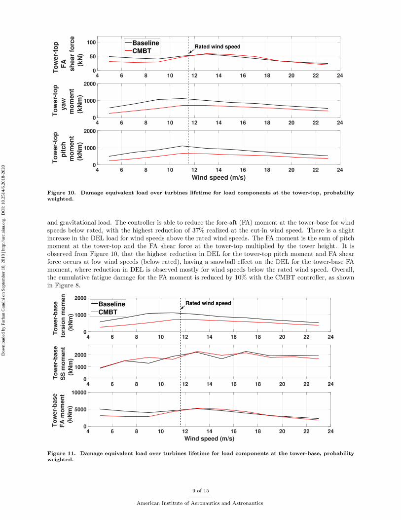
Moreover, the camber morphing blade tip also has fatigue reduction capability of turbine components,other than the rotor. Figure 10 shows the damage equivalent load, over a range of wind speeds, respectivelyfor the fore-aft (FA) shear force, pitch, and yaw moments at the tower-top. Below the rated wind speed,the CMBT controller reduced the DEL for the FA shear force but increases slightly for higher wind speedsbetween 13m/s-19m/s. The net effect is that, using the CMBT controller, the fatigue damage for the FAshear force is sightly decreased by 8% (see Figure 8).
Furthermore, the controller reduced the damage equivalent load for the pitch and yaw moments, at thetower-top, respectively by 38% and 35% at rated wind speed. The steep reduction for these two componentsis a direct effect of the controller design. The gains of the controller are based on Coleman transformation ofthe out-of-plane blade tip displacement in yaw and pitch direction which strongly affect the aforementionedload components.
Finally, the CMBT controller is able to reduce the fatigue damage at the tower-base, as shown in Figure11. A reduction of 35%, at rated speed, is observed for the torsional moment. There is in average noreduction in the side-side (SS) moment at the tower-base. The lack in reduction is to due to the fact thatthis load component is affected mainly by aerodynamic drag and gravitational load. It is already observedin Figure 9 that the controller is not able to mitigate vibration loads caused primarily by aerodynamic drag
8 of 15
American Institute of Aeronautics and Astronautics
Dow
nloa
ded
by F
arha
n G
andh
i on
Sept
embe
r 10
, 201
8 | h
ttp://
arc.
aiaa
.org
| D
OI:
10.
2514
/6.2
018-
2020
4 6 8 10 12 14 16 18 20 22 24
To
we
r-to
p
FA
sh
ea
r fo
rce
(k
N)
0
50
100 Baseline
CMBT
4 6 8 10 12 14 16 18 20 22 24
To
we
r-to
p
ya
w
mo
me
nt
(kN
m)
0
1000
2000
Wind speed (m/s)
4 6 8 10 12 14 16 18 20 22 24
To
we
r-to
p
pit
ch
mo
me
nt
(kN
m)
0
1000
2000
Rated wind speed
Figure 10. Damage equivalent load over turbines lifetime for load components at the tower-top, probabilityweighted.
and gravitational load. The controller is able to reduce the fore-aft (FA) moment at the tower-base for windspeeds below rated, with the highest reduction of 37% realized at the cut-in wind speed. There is a slightincrease in the DEL load for wind speeds above the rated wind speeds. The FA moment is the sum of pitchmoment at the tower-top and the FA shear force at the tower-top multiplied by the tower height. It isobserved from Figure 10, that the highest reduction in DEL for the tower-top pitch moment and FA shearforce occurs at low wind speeds (below rated), having a snowball effect on the DEL for the tower-base FAmoment, where reduction in DEL is observed mostly for wind speeds below the rated wind speed. Overall,the cumulative fatigue damage for the FA moment is reduced by 10% with the CMBT controller, as shownin Figure 8.
4 6 8 10 12 14 16 18 20 22 24
To
we
r-b
as
e
tors
ion
mo
me
nt
(kN
m)
0
1000
2000Baseline
CMBT
4 6 8 10 12 14 16 18 20 22 24
To
we
r-b
as
e
SS
mo
me
nt
(kN
m)
0
1000
2000
Wind speed (m/s)
4 6 8 10 12 14 16 18 20 22 24
To
we
r-b
as
e
FA
mo
me
nt
(kN
m)
0
5000
10000
Rated wind speed
Figure 11. Damage equivalent load over turbines lifetime for load components at the tower-base, probabilityweighted.
9 of 15
American Institute of Aeronautics and Astronautics
Dow
nloa
ded
by F
arha
n G
andh
i on
Sept
embe
r 10
, 201
8 | h
ttp://
arc.
aiaa
.org
| D
OI:
10.
2514
/6.2
018-
2020
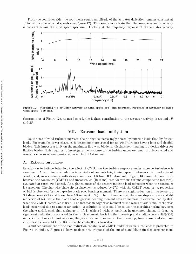
From the controller side, the root mean square amplitude of the actuator deflection remains constant at4 for all considered wind speeds (see Figure 12). This seems to indicate that the average actuator activityis constant across the wind speed spectrum. Looking at the frequency response of the actuator activity
Wind speed (m/s)
4 6 8 10 12 14 16 18 20 22 24RM
S M
orp
hin
g a
ng
leti
p
(d
eg
)
0
2
4
6
Frequency (Hz)
0.1 0.2(1P) 0.4(2P) 0.6(3P) 0.8 1 1.2 1.4 1.6 2|Mo
rph
ing
an
gle
tip|
(de
g)
@ r
ate
d w
ind
sp
ee
d
0
0.5
1
1.5
Figure 12. Morphing tip actuator activity vs wind speed(top) and frequency response of actuator at ratedwind speed (bottom).
(bottom plot of Figure 12), at rated speed, the highest contribution to the actuator activity is around 1Pand 2P .
VII. Extreme loads mitigation
As the size of wind turbines increase, their design is increasingly driven by extreme loads than by fatigueloads. For example, tower clearance is becoming more crucial for up-wind turbines having long and flexibleblades. This imposes a limit on the maximum flap-wise blade tip displacement making it a design driver forflexible blades. This requires to investigate the response of the turbine under extreme turbulence wind andseveral scenarios of wind gusts, given in the IEC standard.
A. Extreme turbulence
In addition to fatigue behavior, the effect of CMBT on the turbine response under extreme turbulence isexamined. A ten minute simulation is carried out for hub height wind speed, between cut-in and cut-outwind speed, in accordance with design load case 1.3 from IEC standard. Figure 13 shows the load ratiobetween the controlled (CMBT) and uncontrolled (Baseline) case for various turbine components (sensors),evaluated at rated wind speed. At a glance, most of the sensors indicate load reduction when the controlleris turned on. The flap-wise blade tip displacement is reduced by 27% with the CMBT actuator. A reductionof 14% is observed for the flap-wise blade root bending moment. There is a slight reduction in the tower-topSS shear force (5%) and tower base SS moment (3%). The roll moment at the tower-top also sees a slightreduction of 5%, while the blade root edge-wise bending moment sees an increase in extreme load by 32%when the CMBT controller is used. The increase in edge-wise moment is the result of additional chord-wiseloads generated due to camber actuation. A solution to this could be to use the morphing technology overthe whole airfoil, such that a change in lift is achieved without resulting in unwanted change in drag. Asignificant reduction is observed in the pitch moment, both for the tower-top and shaft, where a 48%-50%reduction is observed. Furthermore, the yaw/torsional moment at the tower-top, tower-base, and shaft seea decrease between 44% to 50% when the controller is turned on.
A further assessment of the load reduction capability of CMBT under extreme turbulence is presented inFigures 14 and 15. Figure 14 shows peak to peak response of the out-of-plane blade tip displacement (top)
10 of 15
American Institute of Aeronautics and Astronautics
Dow
nloa
ded
by F
arha
n G
andh
i on
Sept
embe
r 10
, 201
8 | h
ttp://
arc.
aiaa
.org
| D
OI:
10.
2514
/6.2
018-
2020

CM
BT
/Ba
se
lin
e
0
0.2
0.4
0.6
0.8
1
1.2
1.4
Blade tip O
P displacement
Blade root edgewise m
oment
Blade root fla
pwise moment
Tower-top yaw m
oment
Tower-top ro
ll moment
Tower-top pitc
h moment
Tower-base SS m
oment
Tower-base FA m
oment
Tower-base to
rsion moment
Tower-top FA shear f
orce
Tower-top SS shear f
orce
Shaft pitc
h moment
Shaft yaw m
oment
Nominal level
Figure 13. Peak-to-peak load ratio with and without CMBT controller due to extreme turbulence duringpower production, at rated wind speed (OP: out-of-plane, SS: side-side, FA: fore-aft).
and rotor thrust (bottom) as a function of the hub height wind speed. The controller is able to reduce themaximum out-of-plane blade tip displacement across the wind speed rage, with a largest reduction of 31%realized at the cut-out wind speed. Furthermore, it is observed that the reduction in blade tip displacementincreases for increasing wind speed. There is modest reduction in the minimum blade tip displacement, withnegligible reduction observed for low wind speeds. The controller is also able to reduce the yaw moment atthe tower-top, across the wind speed range. A maximum reduction of 61% is realized at 15m/s. The yaw
4 6 8 10 12 14 16 18 20 22 24
Bla
de-t
ip
ou
t-o
f-p
lan
e
dis
pla
cem
en
t
(m
)
-5
0
5
10
15
Baseline
CMBT
Wind speed (m/s)4 6 8 10 12 14 16 18 20 22 24
To
wer-
top
yaw
mo
men
t
(kN
m)
-10
-5
0
5
10
Rated wind speed
Figure 14. Extreme load vs wind speed due to extreme turbulence during power production.
moment at the tower-top is caused by asymmetric loading of the rotor disk, meaning that one side of the
11 of 15
American Institute of Aeronautics and Astronautics
Dow
nloa
ded
by F
arha
n G
andh
i on
Sept
embe
r 10
, 201
8 | h
ttp://
arc.
aiaa
.org
| D
OI:
10.
2514
/6.2
018-
2020
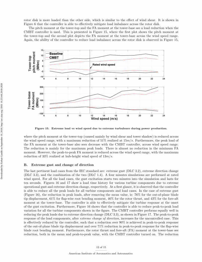
rotor disk is more loaded than the other side, which is similar to the effect of wind shear. It is shown inFigure 6 that the controller is able to effectively mitigate load imbalance across the rotor disk.
The pitch moment at the tower-top and the FA moment at the tower-base see a load reduction when theCMBT controller is used. This is presented in Figure 15, where the first plot shows the pitch moment atthe tower-top and the second plot depicts the FA moment at the tower-base across the wind speed range.Again, the ability of the controller to reduce load imbalance across the rotor disk is observed in Figure 15,
4 6 8 10 12 14 16 18 20 22 24
To
we
r-to
p
pit
ch
mo
me
nt
(MN
m)
-10
-5
0
5
10
15
Baseline
CMBT
Wind speed (m/s)4 6 8 10 12 14 16 18 20 22 24
To
we
r-b
as
e
FA
mo
me
nt
(MN
m)
-100
0
100
200
300
Rated wind speed
Figure 15. Extreme load vs wind speed due to extreme turbulence during power production.
where the pitch moment at the tower-top (caused mainly by wind shear and tower shadow) is reduced acrossthe wind speed range, with a maximum reduction of 51% realized at 15m/s. Furthermore, the peak load ofthe FA moment at the tower-base also sees decrease with the CMBT controller, across wind speed range.The reduction is mainly for the maximum peak loads. There is almost no reduction in the minimum FAmoment. However, the peak-to-peak FA moment is reduced across the wind speed range, with the maximumreduction of 33% realized at hub-height wind speed of 13m/s.
B. Extreme gust and change of direction
The last pertinent load cases from the IEC standard are: extreme gust (DLC 3.2), extreme direction change(DLC 3.3), and the combination of the two (DLC 1.4). A four minutes simulations are performed at ratedwind speed. For all the load cases, the gust excitation starts two minutes into the simulation and lasts forten seconds. Figures 16 and 17 show a load time history for various turbine components due to extremeoperational gust and extreme direction change, respectively. At a first glance, it is observed that the controlleris able to reduce all the peak loads for all turbine components and load cases. In the case of extreme gust(Figure 16), the reduction in peak loads, after removing the mean value, is: 76% for the out-of-plane bladetip displacement, 61% for flap-wise root bending moment, 46% for the rotor thrust, and 43% for the fore-aftmoment at the tower-base. The controller is able to effectively mitigate the turbine response at the onsetof the gust excitation. Furthermore, Figure 16 shows that the controller is able to reduce peak-to-peak loadvariation for all the turbine components shown in the figure. The CMBT controller performs equally well inreducing the peak loads due to extreme direction change (DLC 3.3), as shown in Figure 17. The peak-to-peakresponse of the load components, after extreme change of direction, increases for the uncontrolled case. Thisis effectively reduced by the controller, such that a reduction over 90% is achieved in peak-to-peak responseof the out-of-plane blade tip displacement and over 71% reduction in peak-to-peak response for the flap-wiseblade root bending moment. Furthermore, the rotor thrust and fore-aft (FA) moment at the tower-base seereduction, both in the mean and peak-to-peak value, with the CMBT controller turned on. The reduction
12 of 15
American Institute of Aeronautics and Astronautics
Dow
nloa
ded
by F
arha
n G
andh
i on
Sept
embe
r 10
, 201
8 | h
ttp://
arc.
aiaa
.org
| D
OI:
10.
2514
/6.2
018-
2020

Figure 16. Turbine response to extreme operational gust (at rated wind speed).
in peak-to-peak response of over 50% for both load components.
Figure 17. Turbine response to extreme direction change (at rated wind speed).
Overall, the controller is also able to reduce peak loads caused by extreme gust and extreme directionchange. Furthermore, it should be noted that the critical load case for determining the ultimate loads isextreme turbulence during power production (DLC 1.3), since the magnitude of the peak responses fromextreme turbulence exceed those from gust excitation or direction change.
VIII. Conclusions
An active control concept based on camber morphing blade tip (CMBT) is proposed for load mitigationon multi megawatt scale HAWTs. A span-wise variation of camber at the outer blade region is proposed thatblends seamlessly to the non-morphing part of the rotor blade. The NREL 5MW reference turbine is used asbaseline design, where the outer 30% of the blade is linearly cambered with the maximum camber realizedat the blade tip. 30% of NACA60-618 airfoil’s trailing edge is cambered on the basis of sufficient change inlift (∆cl) without significant increase in drag (high ∆cl
∆cd) compared to the baseline airfoil. A PID controller
is implemented for the camber morphing blade tip. Several simulations in accordance with the IEC standardare carried out using the open source code FAST, after extending the capability of the software to includethe effect of actively morphing the rotor blade during simulation.
The results show that the proposed method is capable of reducing vibratory and ultimate loads:
• The CMBT controller is able to reduce the fatigue loads for most of the wind turbine components. Areduction of 24% in fatigue load is observed for the flap-wise blade root bending moment when theCMBT controller is used. Furthermore, higher reduction in fatigue loads is observed for the pitch
13 of 15
American Institute of Aeronautics and Astronautics
Dow
nloa
ded
by F
arha
n G
andh
i on
Sept
embe
r 10
, 201
8 | h
ttp://
arc.
aiaa
.org
| D
OI:
10.
2514
/6.2
018-
2020
and yaw moment at the tower-top, where the reduction is of the order 36%. However, the controllerslightly increased the fatigue load for the edge-wise blade root moment. This could be the result ofthe controller design witch uses feedback of only out-of-plane blade tip measurements and no in-planemeasurements. A control design based on the full dynamic state of the blade could result furtherreduction in fatigue loads for all wind turbine components.
• The controller is also able to mitigate the effect of extreme turbulence on various turbine components.Most notable reduction in extreme loads is for: out-of-plane blade tip displacement (31%), yaw momentat tower-top (61%), pitch moment at tower-top (51%), and fore-aft moment at the tower base (33%).The large reduction in ultimate loads indicate that the controller is able to reduce load imbalanceacross the rotor disk.
• Similar to the ultimate loads due to extreme turbulence, the controller is also able to minimize thepeak-to-peak response of multiple turbine components due to various gust excitations given in the IECstandard. The reduction in turbine response due to extreme gust is 43% for the fore-aft moment atthe tower base and 76% for the out-of-plane blade tip displacement. Furthermore, the controller is alsoable to mitigate the peak-to-peak response of the turbine due to extreme direction change, resultingin over 90% reduction of peak-to-peak response for the out-of-plane blade tip displacement.
• The highest contribution to the actuator activity for the CMBT controller, under periodic and stochas-tic (normal turbulence) excitation, is around 1P and 2P . This is the consequence of the controllerdesign, in that the controller is tuned to reduce the harmonic response of the out-of-plane blade tip dis-placement caused by periodic excitation. Furthermore, the average actuator activity is nearly constantacross the wind speeds when used to mitigate fatigue loads.
Overall, the controller is able to mitigate both fatigue loads and ultimate loads due to extreme turbulenceand different gust excitations. It should be noted that the present study does not consider the completebenefit of the load alleviating capability of CMBT actuator. The reduction in fatigue and ultimate loadsmeans that wind turbine blades outfitted with CMBT controller can be designed lighter or longer for higherenergy extraction without increase in weight. This will result in either increase of annual energy capture orreduced component cost, which will lower the cost of energy.
Acknowledgment
This study was funded by the New York State Energy Research and Development Authority (NYSERDA)under Award No. 58059, Continuously Conformable Wind-Turbine Blade Tip, with Mr. Gregory Pedrick asthe Program Manager.
References
1Bottasso, C. L., Croce, A., Gualdoni, F., Montinari, P., and Riboldi, C. E., “Articulated blade tip devices for loadalleviation on wind turbines,” Wind Energy Science, Vol. 1, No. 2, 2016, pp. 297.
2Bottasso, C., Campagnolo, F., Croce, A., and Tibaldi, C., “Optimization-based study of bend–twist coupled rotor bladesfor passive and integrated passive/active load alleviation,” Wind Energy, Vol. 16, No. 8, 2013, pp. 1149–1166.
3Bottasso, C. L., Croce, A., Gualdoni, F., and Montinari, P., “Load mitigation for wind turbines by a passive aeroelasticdevice,” Journal of Wind Engineering and Industrial Aerodynamics, Vol. 148, 2016, pp. 57–69.
4Andersen, P. B., Henriksen, L., Gaunaa, M., Bak, C., and Buhl, T., “Deformable trailing edge flaps for modern megawattwind turbine controllers using strain gauge sensors,” Wind Energy, Vol. 13, No. 2-3, 2010, pp. 193–206.
5Bernhammer, L. O., van Kuik, G. A., and De Breuker, R., “Fatigue and extreme load reduction of wind turbine compo-nents using smart rotors,” Journal of Wind Engineering and Industrial Aerodynamics, Vol. 154, 2016, pp. 84–95.
6Bergami, L. and Poulsen, N. K., “A smart rotor configuration with linear quadratic control of adaptive trailing edge flapsfor active load alleviation,” Wind Energy, Vol. 18, No. 4, 2015, pp. 625–641.
7Chow, R. and van Dam, C., “Computational investigations of deploying load control microtabs on a wind turbine airfoil,”45th AIAA Aerospace Sciences Meeting and Exhibit , 2007, p. 1018.
8Baker, J., Standish, K., and van Dam, C., “Two-dimensional wind tunnel and computational investigation of a microtabmodified S809 airfoil,” 43rd AIAA Aerospace Sciences Meeting and Exhibit , 2005, p. 1186.
9Nakafuji, D., van Dam, C., Michel, J., and Morrison, P., “Load control for wind turbines a non-traditional microtabapproach, AIAA 2002-0054,” Proceedings of the 40th AIAA/ASME, Reno, NV, USA, 2002.
10Yen, D., van Dam, C., Smith, R., and Collins, S., “Active load control for wind turbine blades using MEM translationaltabs,” 20th 2001 ASME Wind Energy Symposium, 2001, p. 31.
14 of 15
American Institute of Aeronautics and Astronautics
Dow
nloa
ded
by F
arha
n G
andh
i on
Sept
embe
r 10
, 201
8 | h
ttp://
arc.
aiaa
.org
| D
OI:
10.
2514
/6.2
018-
2020
11Jonkman, J. M. and Buhl Jr, M. L., “FAST User’s Guide-Updated August 2005,” Tech. rep., National Renewable EnergyLaboratory (NREL), Golden, CO., 2005.
12Jonkman, J., Butterfield, S., Musial, W., and Scott, G., “Definition of a 5-MW reference wind turbine for offshore systemdevelopment,” National Renewable Energy Laboratory, Golden, CO, Technical Report No. NREL/TP-500-38060 , 2009.
13Van Rooij, R., “Modification of the boundary layer calculation in RFOIL for improved airfoil stall prediction,” ReportIW-96087R TU-Delft, the Netherlands, 1996.
14Moriarty, P. J. and Hansen, A. C., “AeroDyn theory manual,” Tech. rep., National Renewable Energy Lab., Golden, CO(US), 2005.
15Jonkman, B. J. and Buhl Jr, M. L., “TurbSim users guide,” National Renewable Energy Laboratory, 2009.16Buhl Jr, M. L., “RunIEC Users Guide,” Tech. rep., National Renewable Energy Lab., USA., 2001.17Bossanyi, E., Witcher, D., and Mercer, T., “Project UpWind: Controller for 5MW reference turbine,” Contract , 2009,
pp. 1–18.18Commission, I. E. et al., “IEC 61400-1: Wind turbines part 1: Design requirements,” International Electrotechnical
Commission, 2005.19Kalverla, P. C., Steeneveld, G.-J., Ronda, R. J., and Holtslag, A. A., “An observational climatology of anomalous wind
events at offshore meteomast IJmuiden (North Sea),” Journal of Wind Engineering and Industrial Aerodynamics, Vol. 165,2017, pp. 86–99.
20Hayman, G., “Mlife theory manual for version 1.00,” National Renewable Energy Laboratory, Golden, CO , 2012.21Hopman, P., Kunst, P., and Pronk, A., “A renewed interpretation method for fatigue measurements, verification of miners
rule,” 4th Eurobitume Symposium in Madrid , Vol. 1, 1989, pp. 557–561.22Barlas, A. K., Active aerodynamic load control on wind turbines: Aeroservoelastic modeling and wind tunnel experiments,
2011.23Andersen, P. B., Gaunaa, M., Bak, C., Buhl, T., and Poulsen, N. K., Advanced load alleviation for wind turbines
using adaptive trailing edge flaps: sensoring and control , Technical University of DenmarkDanmarks Tekniske Universitet,Department of Solid MechanicsInstitut for Faststofmekanik, 2010.
15 of 15
American Institute of Aeronautics and Astronautics
Dow
nloa
ded
by F
arha
n G
andh
i on
Sept
embe
r 10
, 201
8 | h
ttp://
arc.
aiaa
.org
| D
OI:
10.
2514
/6.2
018-
2020