LO - apps.dtic.mil
21
AFML-TR-76.174 WRIGHT-PATTERSON TECHPICAL LIBRARY WPA FB, 0. 45433 A CRACK GROWTH GAGE FOR ASSESSING FLAW GROWTH POTENTIAL IN STRUCTURAL COMPONENTS "METALS BEHAVIOR BRANCH METALS AND CERAMICS DIVISION OCTOBER 1976 TECHNICAL REPORT AFML-TR-76-174 FINAL REPORT FOR PERIOD MARCH 1976 - JULY 1976 co LO Approved for public release; distribution unlimited Q) 0 0 AIR FORCE MATERIALS LABORATORY 0 AIR FORCE WRIGHT AERONAUTICAL LABORATORIES J AIR FORCE SYSTEMS COMMAND WRIGHT-PATTERSON AIR FORCE BASE, OHIO 45438
Transcript of LO - apps.dtic.mil

AFML-TR-76.174 WRIGHT-PATTERSON
TECHPICAL LIBRARY
WPA FB, 0. 45433
A CRACK GROWTH GAGE FOR ASSESSING FLAWGROWTH POTENTIAL IN STRUCTURAL COMPONENTS
"METALS BEHAVIOR BRANCHMETALS AND CERAMICS DIVISION
OCTOBER 1976
TECHNICAL REPORT AFML-TR-76-174FINAL REPORT FOR PERIOD MARCH 1976 - JULY 1976 co
LO
Approved for public release; distribution unlimited Q)0
0AIR FORCE MATERIALS LABORATORY 0AIR FORCE WRIGHT AERONAUTICAL LABORATORIES JAIR FORCE SYSTEMS COMMANDWRIGHT-PATTERSON AIR FORCE BASE, OHIO 45438

NOTICE
When Government drawings, specifications, or other data are used for any purpose
other than in connection with a definitely related Government procurement operation,
the United States Government thereby incurs no responsibility nor any obligation
whatsoever; and the fact that the Government may have formulated, furnished, or in
any way supplied the said drawings, specifications, or other data, is not to be
regarded by implication or otherwise as in any manner licensing the holder or any other
person or corporation, or conveying any rights or permission to manufacture, use, or
sell any patented invention that may in any way be related thereto.
This report has been reviewed by the Information Office (10) and is releasable to
the National Technical Information Service (NTIS). At NTIS, it will be available to
the general public, including foreign nations.
This technical report has been reviewed and is approved for publication.
R.L. CRANE A.F. GRANDT J. GALLAGHERNondestructive Evaluation Branch Metals Behavior Branch Structural Integrity
Air Force Materials Laboratory Air Force Materials Laboratory BranchAir Force Flight
Dynamics Laboratory
FOR THE COMMANDZR-%
Chief, Metals Behavior BranchMetals and Ceramics DivisionAir Force Materials Laboratory
Copies of this report should not be returned unless return is required by security
considerations, contractural obligations, or notice on a specific document.
AIR FORCE - 29 NOVEMER 76 - 1250

UNCLASSIFIEDSECURITY CLASSIFICATION OF THIS PAGE (Wen Date Entered)
READ INSTRUCTIONSREPORT DOCUMENTATION PAGE BEFORE COMPLETING FORM
I. REPORT NUMBER 12. GOVT ACCESSION NO. 3. RECIPIENT'S CATALOG NUMBER
AFML-TR-76- 174 C
4. TITLE (and Subtitle) S, TYPE OF REPORT 6 PERIOD COVERED
A CRACK GROWTH GAGE FOR ASSESSING FLAW GROWTHPOTENTIAL IN STRUCTURAL COMPONENTS
6. PERFORMING ORG. REPORT NUMBER
7. AUTHOR(&) 8. CONTRACT OR GRANT NUMBER(s)
R. L. CraneA. F. GrandtJ. P. Gallagher
9. PERFORMING ORGANIZATION NAME AND ADDRESS 10. PROGRAM E•_EMENT. PROJECT, TASKAir Force Materials Laboratory & Air Force Flight AREA & WORK UNIT NUMBERS
Dynamics LaboratoryAir Force Systems Command Project No. 2279L h._Patterson Air Force Base. Ohio
I'. coNY ROLLING OFFICE NAME AND ADDRESS 12. REPORT DATEAir Force Materials Laboratory October 1976Air Force Systems Command 13. NUMBER OF PAGES
Wright-Patterson Air Force Base, Ohio 2114. MONITORING AGENCY NAME & ADDRESS(If different from Controlltin Office) IS. SECURITY CLASS. (of this report)
Unclassified
IS., DECk ASSI FICATI ON/ DOWN GRADIN GSCHEDULE
16. DISTRIBUTION STATEMENT (of this Report)
Approved for public release, distribution is unlimited.
'7. DISTRIBUTION STATEMENT (of the abstract entered in Block 20, if different from Report)
IS. SUPPLEMENTARY NOTES
19. KEY WORDS (Continue on reverse aide If necessary and Identify by block number)
Nondestructive Evaluation, Crack Growth, Life Prediction
20. ABSTRACT (Continue on reverse aide If necessary and Identify by block number)A new concept for monitoring the potential for damage accumulation in structur-
al materials is presented. Briefly, the method proposed is to install a pre-flawed gage on a critical component and to monitor its flaw growth nondestruc-tively. The relationship between this flaw size and the potential flaw in thestructure is derived using linear elastic fracture mechanics principles. Exper-imental flaw growth data produced by an aircraft spectrum was used to demon-strate the validity of a degenerate case of this concept. A discussion is alsopresented to show how this method could be implemented in fulfillment of theMil-Std-1530 requirement to track potential flaw growth.
FORM
DD JAN 73 1473 EDITION OF I NOV65 IS OBSOLETE UNCLASSIFIED
SECURITY CLASSIFICATION OF THIS PAGE (Wh~en Data Entered)
FOREWORD
This technical report was prepared by the Metals Behavior Branch,
Metals and Ceramics Division, Air Force Materials Laboratory, Wright-
Patterson Air Force Base, Ohio. The research was conducted under Project
No. 2279, Task No. 22790101 during the period March 1976 to July 1976.
The author would like to acknowledge the significant contributions of
Mr. Jim G. Paine, Systems Research Laboratories, Dayton, Ohio in the
experimental portion of the investigation.
iii
TABLE OF CONTENTS
SECTION PAGE
I INTRODUCTION ................ ......................... 1
II ANALYSIS ...................... ......................... 3
III EXAMPLE RESULTS ................. ... ..................... 6
IV CONCLUDING DISCUSSION ................. .................. 8
REFERENCES ....................... ........................ 10
v

LIST OF ILLUSTRATIONS
Figure Page
1. Schematic View of Crack Gr.•owth Gage Attached to Flawed
Structural Component. Ii
2. Schematic Representation of the Relationship Between the
Gage and Structural Flaw Sizes. 12
3. Analytical Results Showing the Effect of the Initial Gage
Flaw Size on a Typical Gage/Structural Crack Growth
Relationship. 13
4. Analytical Prediction of a Crack Growth at a Hole as a
Function of Crack Size in a Center Cracked Gage. 14
Comparison of Kxperimental Data with the Analytical
Prediction for the Relationship Between Two Different
Flaw Geometries in the Same Specimen (f=l, Eq. 12).
The Specimen Was Subjected to Spectrum Loading. 15
vi

SECTION I
INTRODUCTION
It is the objective of this Technical Report to describe a new concept
for monitoring the potential for damage accumulation in structural materials.
A recent change in Air Force policy is the requirement to track crack growth
potential in a manner that realistically includes the effects of overloads,
hold times, environment, etc. This specific requirement is covered in U.S.A.F.
document MIL-STD-1530A(1) paragraphs 5.4.5, which states "...the objective of
the individual airplane tracking program shall be to predict the potential
flaw growth in critical areas of each airframe that is keyed to damage growth
limits of MIL-A-83444..." and "...tracking analysis method shall be developed
to establish and adjust inspection and repair intervals for each critical
area of the airframe based on the individual airplane usage data." A great
deal of prior work has gone into research and development of techniques, pro-
ceduresjand instruments to assess structural damage accumulation (References 1-
6). The many instruments that were developed to facilitate damage accumulation
tracking are commonly referred to as "fatigue gages," see for example Reference 4.These gages have not been generally successful because it was not possible to
relate the gage response to accumulation of structural damage. The approach
suggested here differs from all previous methods in that a precracked specimen
or "gage" is mounted on the load bearing member, shown schematically in Figure 1,
where it experiences the same displacement and environmental history as the
member. Therefore, the gage crack grow3 in a manner relatable to those possibly
in the structure. Linear elastic fracture mechanics analysis is then employed
to relate crack growth in the gage with the growth of a real or assumed initial
flaw located in the structure. Crack growth in the gage can then be conveniently
examined with NDE techniques during service for an indication of growth of the
assumed structural defect. Moreover, as shown schematically in Figure 2, this
relationship permits allowable maximums for the structural crack size (based on
safety criteria or repair economics) to specify corresponding gage limits.
One of us considered this gage for use on composite structures
where the two principal mechanisms of strength loss, mechanical fatigue and
anvironmental degradation, interact in a complex manner (References 7-9).
1

Since laboratory experiments have shown that even simple moist atmospheric
exposure can reduce the strength and modulus of a composite dramatically,
and because it is not possible to nondestructively predict service life of such
components, designers have been forced to use this new material only in quite
conservative designs. A gage that would integrate the effects of both the
environment and loading on a real time basis and permit frequent nondestructive
examination would be an obvious asset to both the designer and user of composite
structures. With proper design and interpretation such a gage would permit the
prediction of residual service life for composite structures, thus increasing
the confidence in their usage.
In this Technical Report the analytical expressions relating the cracks
in a metal structure and gage are derived and sample calculations are made for
various flaw geometries. An experimental verification of a portion of the mathe-
matical model is also presented. Unfortunately, it was not possible here to
develop a similar model for composite structural componexts because of the lack
of flaw growth laws for these materials. This deficiency will be covered at the
end of this report.
2
SECTION II
ANALYSIS
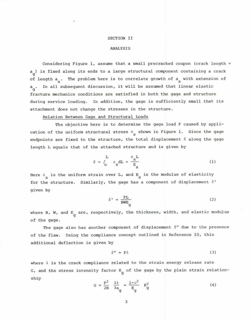
Considering Figure 1, assume that a small precracked coupon (crack length =
a ) is fixed along its ends to a large structural component containing a crack
of length a . The problem here is to correlate growth of a with extension ofs s
a . In all subsequent discussion, it will be assumed that linear elasticgfracture mechanics conditions are satisfied in both the gage and structure
during service loading. In addition, the gage is sufficiently small that its
attachment does not change the stresses in the structure.
Relation Between Gage and Structural Loads
The objective here is to determine the gage load P caused by appli-
cation of the uniform structural stress a shown in Figure 1. Since the gages
endpoints are fixed to the structure, the total displacement 6 along the gage
length L equals that of the attached structure and is given by
L acL6 =f cdL = - (1)
o s Es
Here e is the uniform strain over L, and E is the modulus of elasticitys s
for the structure. Similarly, the gage has a component of displacement 6'
given by
6= PL (2)BWE
g
where B, W, and E are, respectively, the thickness, width, and elastic modulusg
of the gage.
The gage also has another component of displacement 6" due to the presence
of the flaw. Using the compliance concept outlined in Reference 10, this
additional deflection is given by
6" = PA (3)
where A is the crack compliance related to the strain energy release rate
G, and the stress intensity factor K of the gage by the plain strain relation-g
ship p2 A 1-V 2
G = -= K K2 (4)2B 3a E gg g

Here v is Poisson's ratio for the gage. For plane stress conditions, v=0
in Eq. (4). Expressing the stress intensity factor in the form
K= /Paa (5)BW
where $ is a dimensionless geometry factor which can depend on crack length,
Eqs. (4) and (5) reduce toa
= 2(1-v2) g aý 2 da (6)E BW2 f g
g0
Thus, the displacement of the gage is given by
oL
+ 6 PL +s L (7)E BW E
g s
which when solved for gage load with Eq. (6) becomes
P BW E L a BWf (8)P as E s L .l BW 2 v aao g s
where f is the bracketed quantity defined by Eq. (8).
Thus the load in the cracked gage is directly related to the uniform gross
stress in the structure. This uniform stress is the same stress that influences
the crack growth behavior at the structural detail of interest. It now remains
to describe how the crack growth behavior of the detail is related to that in
the gage, i.e., to provide the transfer function.
Gage and Structural Crack Relation
da = (9)dF
where da/dF is the average crack extension per block of service usage (e.g.,
an aircraft flight) and C and m are empirical constants. The parameter K
is a stress intensity factor that senses the influence of stress history on
the crack growth process. As such, K is normally obtained by multiplying a
stress history characterizing parameter (e.g., a = rms stress range) by the
stress intensity factor coefficient for the geometry of interest. For the
structure, K would be
4

K= (10)a s s s
Now assume that both the gage and structure are made from material which have
the same Paris exponent m in Eq. (9). Using the fact that both gage and
structure see the same number of loading blocks F, integrating Eq. (9) for a
fixed number of flights with Eq. (5) and Eq. (10) yieldsa a
F = da = g (11)C (3 J7W B)m (P )ra m
a s s s a gBW gos og
which reduces by employing Eq. (8) and canceling like quantities to
C _ s da = f gde (12)
a s a gos og
Note that Eq. (12) is independent of stress history (explicitly), so the as
versus a response is also anticipated to be independent of stress history.gAlso note that the constants C and C from Eq. (9) have been retained in9 5
Eq. (12). This permits the use of two different materials for the gage and
structure. It will also permit designers to account for variability in mate-
rial properties if the same metal is used in both structure and gage.
A numerical integration scheme was employed here to solve Eq. (12) for
a as a function of a . First, the integration of the right-hand side ofs gEq. (12) was carried out with the trapezoidal rule together with Romberg's
extrapolation method. The upper bound of the absolute error for this pro-
cedure was specified to be less than 1 x 10⁻⁵. Next, an upper limit for the
left-hand side of Eq. (12) was chosen and the integration performed as before.
Depending on the agreement of the left-hand value with the previously deter-
mined right-hand side, an adjustment was made in the upper limit (a ) of thes
left integral and the process repeated until the values of the two integrals
agreed to within 0.02%.
5

SECTION III
EXAMPLE RESULTS
Solving Eq. (12) by the numerical procedure described above, the relation
between structural and gage flaw lengths was found for several geometric con-
figurations. Results from the sample cases are briefly described below.
In all examples, the structure and gage had the same C, E, and m, while
Poisson's ratio for the gage was 0.333.
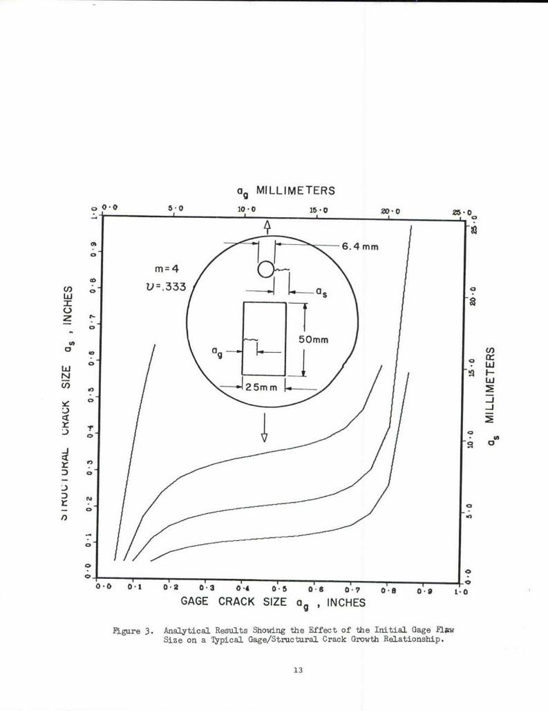
Consider an edge cracked coupon (50 mm long by 25 mm wide) attached to
a large plate containing a 6.4 mm diameter radially cracked hole (length = 1.3 mm)
as shown in Figure 3. Numerical results from Eq. (12) for m = 4 (a constant
amplitude fatigue crack growth rate exponent typical of many structural materials)
are shown in Figure 3 for various initial gage flaw sizes (aog = 1.3, 1.9, 2.5 and
3.8 mm). Note that the results show a strong dependence on initial crack size,
varying from a fast growing structural crack (a = a os=.3 mm) to a response
where gage crack growth significantly amplifies corresponding extension of the
structural flaw (a = 1.3 mm and a = 3.8 mm). Thus, varying the initialos ogcrack size provides one means for designing a gage for various degrees of
amplification of structural crack growth.
Figure 4 shows the results obtained for a study similar to the one above,
but with a gage containing a center crack rather than an edge crack. The
material parameters and gage dimensions are the same as in the previous example.
The variation in initial flaw sizes again demonstrates the two cases of a gage
which is insensitive to structural crack growth (a = 1.3 mm) and one which isgo
highly sensitive to structural flaw growth (a = 3.8 mm). However, for angoinitial gage flaw size of 2.5 mm the gage demonstrates growth characteristics
which permit it to be usable over a wide range of flaw sizes in the structure,
between 1.3 mm and 23 mm.
If the gage flaw is located in the structural component rather than in an
attached coupon and sees the same remote stress, f = 1 in Eq. (12). Experi-
mental data (Reference 12) for this special case, provided a means of checking
Eqs. (9) to (12) of the model. Briefly, the experimental set-up was as follows:
6

Long specimens of 7075-T651 aluminum (width = 150 mm, thickness = 12.7 am)containing both a radially cracked hole and a center crack in series as shownin Figure 5, were subjected to complex variable amplitude loading representative
of an aircraft stress history. Since the crack growth exponent m was not known
beforehand, computations were made for m = 3, 4, and 5; a range encompassingexpected values for this material. Of course in practice, the value of the
Paris exponent, m, would be a well documented constant from spectrum fatiguetests of the structure and gage material. Note in Figure 5 that these analyticalpredictions closely bound the test data. Thus this excellent agreement betweenexperiment and analysis lends credence to the validity of Eq. (9), and subse-
quent development of Eq. (12). Agairý it should be emphasized that the
numerical calculations required no knowledge of the actual load history applied
to the test specimen.
7
SECTION IV
CONCLUDING DISCUSSION
A new concept for monitoring flaw growth in structural components with
a flawed gage has been presented along with a mathematical model for the
relation between the structural and gage flaw sizes. This relationship,
given by Eq. (12), and demonstrated in Figures 3-5, provides the means for
designing a simple crack growth gage capable of "tail number" tracking a fleet
of structures for extension of potential or known flaws. The proposed gage
would have no moving or electronic components to malfunction, need only mini-
mum instrumentation and could be designed for various degrees of amplification
between structural and gage crack lengths.
Since Eq. (12) relates the gage crack length with the assumed structural
flaw size and depends only on geometric factors and material properties,
extensive records of service loads would not be required to estimate flaw
growth. Indeed, the gage provides a direct measure of crack growth, acting
as an analog computer which collects, stores, and analyzes the severity of
the input loads, and then responds with the appropriate flaw extension. Thus,
the loading conditions which affect flaw growth (i.e., stress level, overloads,
temperature, environment, etc.) should be integrated in the gage prediction
of structural crack length on a real time basis. Although extensive experi-
mental testing of this gage capability remains for future work, it is encouraging
that the data shown in Figure 5 provide a preliminary verification of the trans-
fer function model described in Eq. (12).
The authors believe that the crack gage described can be used by
logistics management for maintenance decisions in both of the following two
ways: (1) as a simple "go/no go" measure of the necessity for inspecting or
modifying any given structure, or (2) in conjunction with a Normalized Crack
Growth Curve (Reference 11). The crack gage-structural crack transfer function
(Eq. (12)) and the Normalized Crack Growth CUrve associated with the structural
crack would collectively provide a direct indication of structural cra3k
size and an estimation of remaining useful service life. This second decision
making concept is explored more fully in Reference 12.
8

While this work concentrated on metallic structure, this concept couldpotentially be used to predict the residual life of composite structuralcomponents. In this case, the use of the crack growth analogy may have to
be avoided because it has been shown that composites rarely fail by thegrowth of a single dominant crack (Reference 13). Instead, composites seem
to accumulate damage via the growth of many fine cracks, delaminations, etc.around pre-existing flaws or stress concentrations. It might have been
possible to account for this type of damage accumulations in the above mathe-
matical model if a unified theory for damage accumulation in compositesexisted. Unfortunately it does not, thereby preventing our extension of the
crack growth gage concept to these materials.
9

REB•FBENCES
1. A. P. Shewmaker and J. A. Wagner, Proc. Air Force Conference on Fatigue and
Fracture of Aircraft Structures and Materials, AFFDL-TR-70-1441, WPAFB, Ohio,
1970, 833.
2. D. H. Whitford and R. J. Dominic, Proc. Air Force Conference on Fatigue and
Fracture of Aircraft Structures and Materials, AFFDL-TR-70-l44, WPAFB, Ohio,
1970, 847.
3. T. L. Haglage and H. A. Wood, Proc. Air Force Conference on Fatigue and
Fracture of Aircraft Structures and Mateials, AFFDL-TR-70-144., WPAFB, Ohio.,
1970, 137.
4. D. R. Harting, Experimental Mechanics, 6, 1966, 19A.
5. J. C. Spanner and McElroy, Ed., Monitoring Structural Integrity by Acoustic
Emission, ASTM STP 571, 1975.
6. M. D. Coffin and C. F. Tiffany, Journal of Aircraft, 1, 1976, 93.
7. C. E. Browning, G. E. Husman, and J. M. Whitney, Composite MaterialsTesting and Design (Fourth Conference), ASTM STP, American Society for
Testing and Materials, 1976.
8. D. H. Kaelble, P. J. Dynes, and L. Maus, "Hydrothermal Aging of Composite
Materials; Part 1, Interfacial Aspects," Journal of Adhesion, In Press.
9. D. H. Kaelble, P. J. Dynes, and L. Maus, "Hydrothermal Aging of Composite
Materials; Part 2, Matrix Aspects," ibid.
10. H. Okamura, K. Watambe, and T. Takano, Progress in Faaw Growth and Fracture
Toughness Testing, ASTM STP 536, 1973, 423.
11. J. P. Gallagher and H. D. Stalnaker, Proc. AIAA/ASME/SAE 17th Structures,
Structural Dynamics and Materials Conference, Valley Forge, PA, 1976, 486.
12. J. P. Gallagher, A. F. Grandt, and R. L. Crane, "Tracking Crack Growth
Damage at Control Points, " paper in preparation for presentation at
AIAA/ASME/SAE 18th Annual Structures, Structural Dynamics and Materials
Conference, March 1977.
13. N. J. Pagano, Private Communication, AFTL/NBM, WPAFB, Ohio 45433.
10

w
ai)
0
r4
w
49
aI)
Cl)
a)
o 0)
1-* 4b

I 4"z 1
P-4 0
CD
0 0)4 _ 0
o0 HjN3 MO Q) inio
-iN j12
og MILLIMETERS
o 0"0 4•'0 10-0 1•'0 ;;)0" 0,•'0
6.4ram
m-4 / • \
° k !Z t.-
t 50ram
• °
- • •,• • ,:,=
- , •
oo0'" 1 0" 2 3 0"4 6 0" 8 ? 8 9 1- I0" 0" 0" 0" 0"
GAGE CRACK SIZE ag , INCHES
•igure 3. Analytical Results Showing the Effect of the Initial Gage FlawSize on a Typical Gage/Structural Crack Growth Relationship.
i3

ag , MILLIMETERS005.0 10.0 15.0 ZDO25.0
v 0O.333
z U)
2a w*9
000m
w
010
41

S813~llll s' 09
It 0 5EE a : 4
z P.
* Ls w -P
U) 00: E
W S (0 co0-J d
* E CUEA
0D
E 0
00cic0
0 I I
0:1 6*0o G.oa 4.O 00' 90 Q. .'0 2.0 1-0 0.0
S3HONI 0~ 3ZIS >I3V83 -1v~fliofl~is
F(RNMF NT --RINI [N6~ (11 F I(J 1 - Wc /63