LNG Terminal Regulations Manual Berth No.3 Normal
54
LNG Terminal Regulations Manual Berth No.3 Normal Group: Marketing & Shipping Document No: S01-X01-009 Department: Shipping Revision: 04 Section: Marine Support & Projects Pages: 1 of 54 Disclaimer This document will be maintained live on the RGDMS. The web based document will be the controlled version and revision announcements will be distributed via e-mail to relevant users and published on the web. Copies of extracts of this document, which have been downloaded from the web site, are uncontrolled copies and cannot be guaranteed to be the latest version. TABLE OF CONTENTS Section Title Page Internal Controls .....................................................................................................................3 Purpose ........................................................................................................................5 1.0 Definitions ....................................................................................................................5 2.0 References ...................................................................................................................6 3.0 Roles and Responsibilities ........................................................................................7 4.0 Non Compliance ..........................................................................................................7 5.0 Vessel Documentation ................................................................................................8 6.0 Drug / Alcohol Abuse ..................................................................................................8 7.0 Processes and Requirements ....................................................................................9 8.0 Pre Arrival .....................................................................................................................9 8.1 Berthing & Mooring .......................................................................................................9 8.2 Communication ...........................................................................................................12 8.3 Access & Security .......................................................................................................14 8.4 Safety ..........................................................................................................................16 8.5 State of Readiness ......................................................................................................17 8.6 Environmental Discharge / Ballast Handling ...............................................................19 8.7 Cargo Operations ........................................................................................................20 8.8 Feedback Form ..........................................................................................................25 9.0 Training and Support ................................................................................................26 10.0 Verification Measurement ........................................................................................26 11.0 Feedback and Continual improvement ...................................................................26 12.0 Attachments ..............................................................................................................26 13.0 Appendix A: Ship / Shore Safety Check List ..............................................................27 13.1 Appendix B: Cargo Handling Agreement ...................................................................31 13.2 Appendix C: Pre-Arrival Information ...........................................................................32 13.3 Appendix D: Safety Declaration .................................................................................33 13.4 Appendix E: Communication Agreement ....................................................................33 13.5 Appendix F: Emergency Contacts ...............................................................................35 13.6 Appendix G: Adverse Weather – Terminal Operating Policy ......................................36 13.7 Appendix H: Loading Arm – Operating Envelope Berth ..............................................40 13.8 Appendix I: Mooring Diagram – LNG Berth No.3 ........................................................41 13.9 Appendix I: Terminal Alarms – Berth No.3 ..................................................................42 13.10
Transcript of LNG Terminal Regulations Manual Berth No.3 Normal

LNG Terminal Regulations Manual Berth No.3 Normal
Group: Marketing & Shipping Document No: S01-X01-009
Department: Shipping Revision: 04
Section: Marine Support & Projects Pages: 1 of 54
Disclaimer This document will be maintained live on the RGDMS. The web based document will be the controlled version and revision announcements will be distributed via e-mail to relevant users and published on the web. Copies of extracts of this document, which have been downloaded from the web site, are uncontrolled copies and cannot be guaranteed to be the latest version.
TABLE OF CONTENTS
Section Title Page
Internal Controls ..................................................................................................................... 3
Purpose ........................................................................................................................ 5 1.0
Definitions .................................................................................................................... 5 2.0
References ................................................................................................................... 6 3.0
Roles and Responsibilities ........................................................................................ 7 4.0
Non Compliance .......................................................................................................... 7 5.0
Vessel Documentation ................................................................................................ 8 6.0
Drug / Alcohol Abuse .................................................................................................. 8 7.0
Processes and Requirements .................................................................................... 9 8.0
Pre Arrival ..................................................................................................................... 9 8.1 Berthing & Mooring ....................................................................................................... 9 8.2 Communication ........................................................................................................... 12 8.3 Access & Security ....................................................................................................... 14 8.4 Safety .......................................................................................................................... 16 8.5 State of Readiness ...................................................................................................... 17 8.6 Environmental Discharge / Ballast Handling ............................................................... 19 8.7 Cargo Operations ........................................................................................................ 20 8.8
Feedback Form .......................................................................................................... 25 9.0
Training and Support ................................................................................................ 26 10.0
Verification Measurement ........................................................................................ 26 11.0
Feedback and Continual improvement ................................................................... 26 12.0
Attachments .............................................................................................................. 26 13.0
Appendix A: Ship / Shore Safety Check List .............................................................. 27 13.1 Appendix B: Cargo Handling Agreement ................................................................... 31 13.2 Appendix C: Pre-Arrival Information ........................................................................... 32 13.3 Appendix D: Safety Declaration ................................................................................. 33 13.4 Appendix E: Communication Agreement .................................................................... 33 13.5 Appendix F: Emergency Contacts ............................................................................... 35 13.6 Appendix G: Adverse Weather – Terminal Operating Policy ...................................... 36 13.7 Appendix H: Loading Arm – Operating Envelope Berth .............................................. 40 13.8 Appendix I: Mooring Diagram – LNG Berth No.3 ........................................................ 41 13.9 Appendix I: Terminal Alarms – Berth No.3 .................................................................. 42 13.10

LNG Terminal Regulations Manual Berth No.3 Normal
Document No: S01-X01-004 Revision No: 04 Page: 2 of 54 Part Number: 000 Issue Date: 08-Aug-16
Appendix J: E.S.D 1 LNG Berth No.3 ......................................................................... 43 13.11 Appendix K: E.S.D 2A (71UZ-3121) ............................................................................ 44 13.12 Appendix L: E.S.D 2B LNG Berth No.3 ....................................................................... 45 13.13 Appendix M: Compatibility Information ........................................................................ 47 13.14 Appendix N: Ship / Shore Feedback Form .................................................................. 50 13.15 Appendix N: Jetty Boil Off Gas Recovery ................................................................... 51 13.16
Custodian of this document: Shipping Manager
Owner of this document: Chief Marketing & Shipping Officer
LNG Terminal Regulations Manual Berth No.3 Normal
Document No: S01-X01-004 Revision No: 04 Page: 3 of 54 Part Number: 000 Issue Date: 08-Aug-16
Internal Controls
Validation
To assure confidence in Company’s policies and practices; RasGas Internal Audit may verify compliance with this document without notice.
Signature Page & Revision History
Review by
SIGNED
03-Aug-16
ADVISOR (Shipping)Jassim Ebrahim Ashkanani
Date
Endorsed by
SIGNED
03-Aug-16
Head of Marine Support & ProjectsKhaled Djebbar
Date
Approved by
SIGNED
03-Aug-16
Shipping ManagerTalal Al-Tamimi
Date
Endorsed by
SIGNED
08-Aug-16
Chief Marketing & Shipping OfficerKhalid Sultan R. Al-Kuwari
Date
Revision Authorization Rev. No.
Date Changed Section
Changed By
Endorsed Approved
Approved
1 09-Jun-09 5,6,7,8,9,13 Capt. Ghani Khaled Djebbar Keith Trotter Nasser Al-Naimi 2 27-Jun-11 2,3,5 & 9 Capt. Ghani Khaled Djebbar Keith Trotter Nasser Al-Naimi 3 02-Oct-13 1,3,9,13 Capt. Ghani Khaled Djebbar Iain Scally Khalid Sultan R. Al-Kuwari 4 08-Aug-16 1,3,8 Jassim Ashkanani Khaled Djebbar Talal Al-Tamimi Khalid Sultan R. Al-Kuwari
Summary of Revisions Rev. No.
Date By Description of Key Changes
0 07-May-07 S. Penumarti Issued for Implementation 1 09-Jun-09 Capt. Ghani Issued for Implementation2 27-Jun-11 Capt. Ghani Issued for Implementation3 02-Oct-13 Capt. Ghani Issued for Implementation4 08-Aug-16 Jassim Ashkanani

LNG Terminal Regulations Manual Berth No.3 Normal
Document No: S01-X01-004 Revision No: 04 Page: 4 of 54 Part Number: 000 Issue Date: 08-Aug-16
Distribution List
The Distribution List shows current users of this manual. Manual users will be provided with the data link for this document. To receive an electronic copy, contact the Head of Documents / Standards.
Manual Users
Job Title
Chief Marketing & Shipping Officer
Shipping Manager
HEAD (Fleet)
HEAD (Marine support & Projects)
HEAD (Marine Risk, Quality & Performance)
SENIOR ADVISOR (Marine)
ADVISOR (Shipping)
SPECIALIST (Loading Master)
RasGas Fleet Admin.
RasGas Loading Master
RasGas Panel & Operations – Offsite
Master of Peteronet LNGC
Master of KoGas LNGC
Master of CPC LNGC
Master of RasGas Charter LNGC
Master of RasGas Sport Charter LNGC
Others as required

LNG Terminal Regulations Manual Berth No.3 Normal
Document No: S01-X01-004 Revision No: 04 Page: 5 of 54 Part Number: 000 Issue Date: 08-Aug-16
Purpose 1.0
The LNG Terminal Regulations have been written to supplement current Ras Laffan Port Regulations so as to ensure safe and efficient operations at RasGas LNG Terminal.
The LNG Terminal Regulations should be read in conjunction with the Ras Laffan Port Regulations so as to ensure that the Terminal Users are compliant with all State/Port Legislation and any other Terminal specific requirements.
These Terminal Regulations were also written so as to provide the Terminal User with a source of additional information and procedures pertinent to all operations at the RasGas LNG Terminal.
APPLICATION
The LNG Terminal Regulations apply to all vessels including persons operating at any berths operated by RasGas within RasLaffan Port.
Definitions 2.0
Term Definition Berth LNG Berth No.3, Ras Laffan Port.
Berth Area The Berth No.3 and the area of land enclosed by and including the Berth No.3 security fence.
Cargo Machinery
Cargo pumps, cargo compressors, cargo vaporizers, reliquefaction plant, inert gas generators, their motors, control equipment, and other cargo handling equipment. It shall also include where appropriate, primary and emergency power supply, circulating pumps, other auxiliary machinery and equipment essential for the safe and efficient operation of the cargo machinery.
Crew Collectively the personnel involved with cargo handling operations, and all other persons related to these operations on behalf of the Ship.
Intrinsically Safe
The condition whereby any spark or thermal effect, generated by the normal operation or accidental failure of the equipment, is incapable, under prescribed test conditions, of igniting a prescribed gas mixture. Any equipment so rated will be certified, by the appropriate body as “intrinsically safe”.
JBOG Jetty Boil Off Gas PO Panel Operator SO Senior Operator SS Shift Supervisor LO Loading Operator LNG Liquefied Natural Gas
Master
When in use in relation to a LNGC, any person having the command of the vessel for the time being and may be construed by the present regulations, at the option of the Master, as a responsible person delegated by the Master to undertake general or specific duties in liaison with the Terminal, provided that the Master shall at all times have sole responsibility for the application of the present regulations.
Naked Lights Open flames, exposed incandescent material or any other unconfined source of ignition.
Permit to Work A document issued by the Terminal, permitting specific work to be performed during a specified period in a defined area under strict safety conditions.
Port Area The area of land and water enclosed by and including, the Main and Lee breakwaters, and the Port security fence.
Port Authority
QP, or any successor of QP, in its capacity as the party entrusted with the management and administration of the Port of Ras Laffan pursuant to the terms of the Emiri Decree No.35 of 1994 and the Council of Ministers Decision No.9 of 1994, as well as the Port Management designated by QC

LNG Terminal Regulations Manual Berth No.3 Normal
Document No: S01-X01-004 Revision No: 04 Page: 6 of 54 Part Number: 000 Issue Date: 08-Aug-16
Term Definition or its successor, to be responsible for the administration and control of the Port. Such management includes the person or persons, his deputies and assistants, authorized by QC, to exercise the powers or perform the duties in respect of making and enforcing regulations, administration and control of the port.
Port Regulations The Ras Laffan Port Regulations. RasGas Ras Laffan Liquefied Natural Gas Co. Ltd.
QP The Qatar Petroleum Corporation.
LNGC A special purpose vessel constructed and equipped for the transportation of liquefied natural gas in bulk as per conditions stipulated on its Certificate of Fitness.
Ship’s Agent Any person or persons authorized by the Nakilat Shipping Agency.
Terminal
RASGAS, as well as the Terminal management designated by RASGAS. Such management includes the person or persons his deputies and assistants, authorized by RASGAS, to exercise the powers or perform the duties in respect of making and enforcing regulations, administration and control of the plant and berths.
Terminal Supervisor Loading Master (designated as PFSO) / Marine Superintendent / Marine Advisor designated by RasGas as the Terminal Management.
References 3.0
RasGas Procedures, Instructions, Specifications and Standards Document Number Document Title
Version 7 issued 30/6/10 RLC Port Regulations S01-X01-008 (28/2/2016) Cargo Handling Manual – RasLaffan LNG Berth No.3 S01-X01-010 Terminal Safety Manual – Ras Laffan LNG Berth No.3 Safety Aspects of the Marine Transportation and Storage of Refrigerated
Liquefied Fuel Gases (SIGTTO) 1995. Safety Guide for Terminals Handling Ships Carrying Liquefied Gases in
Bulk (O.C.I.M.F) 5th Edition 2006 International Safety Guide for Oil Tankers and Terminals 5th Edition 2006 Gulf States Relevant Laws, Protocols and Administrative Guidance such as:
Protocol for the Protection of the Marine Environment against Pollution from Land-based Sources, 21.Feb 1990. Regional Organization for the Protection of the Marine Environmental, ROPME.
Protocol concerning Marine Pollution resulting from Exploration and Exploitation of the Continental Shelf.
Environmental Guidelines and Environmental Protection Criteria for Ras Laffan Industrial City, QP/RLIC.
P13-X03-A6-001_000 Operations Department Training Document
The Master is advised to consult his appointed local Shipping Agent if clarification or interpretation is required of Qatari State Laws, and or Ras Laffan Port Regulations. The Master is advised to consult the Terminal if clarification or interpretation is required of the RasGas LNG Terminal Regulations.

LNG Terminal Regulations Manual Berth No.3 Normal
Document No: S01-X01-004 Revision No: 04 Page: 7 of 54 Part Number: 000 Issue Date: 08-Aug-16
Roles and Responsibilities 4.0
Position or Role Responsibilities
Chief Marketing & Shipping Officer
Is the Owner of the procedure and responsible for the effectiveness of the process and will provide complete support to Custodian in obtaining information and signatures from the identified subject authorities.
Shipping Manager
Is the Custodian of the Procedure and is responsible for coordinating revisions to the procedure and reviewing the contents at least once every two years.
The Master is responsible at all times, for ensuring the safety of his Vessel and Crew. The Master is also responsible for the prevention of accidents and pollution. If the requirements of these regulations conflict with any provisions of vessel specific Operating Manuals and/or vessel specific Emergency Procedures the Master shall bring this to the attention of the Terminal prior to the commencement of cargo handling. The RasGas LNG Terminal Regulations shall not be interpreted as releasing in regard to the Master’s or the crew’s obligations as defined by the appropriate legislation or in regard to their duty to follow the principles of good seamanship under all circumstances.
Non Compliance 5.0
LNGC(s) are accepted for handling LNG at the Berth when they are able to comply with all regulations in respect of the safe containment of cargo and the means for indicating cargo system pressures, temperatures and cargo liquid levels. LNGC(s) are accepted for handling LNG at the Berth on the understanding that operations are conducted safely and expeditiously and that the LNGC vacates the Berth as soon as practicable after operations are completed. Under the following circumstances the Terminal reserves the right to suspend operation and request the removal of any LNGC from the Berth following consultation with the Master:
Flagrant or continuous disregard of Terminal or Port Regulations.
Any defects to vessel, equipment, personnel or operations that in the reasonable opinion of the Terminal present increased risk to the Terminal, the Terminal Personnel or allow for continued safe operation.
When on-board operational performance fails to utilize the available Terminal Facilities satisfactorily and thereby, in the reasonable opinion of the Terminal, constitutes an unacceptable constraint on Terminal operations.
The Terminal will not be held liable for any costs incurred by the LNGC, its Owner, Charterer or Agent as a result of a refusal to load or discharge all or part of a nominated shipment, delay to or suspension of loading, discharging, or any other operation conducted whilst at the Berth, or a requirement to vacate the Berth when the vessel is in contravention of the Terminal Regulations or Ras Laffan Port Regulations.
DEVIATION FROM THE REQUIREMENTS OF THE LNG TERMINAL REGULATIONS OR RAS LAFFAN PORT REGULATIONS MAY ONLY BE PERMISSABLE WITH THE
WRITTEN PERMISSION FROM RAS GAS &/OR WHERE APPLICABLE RAS LAFFAN PORT AUTHORITY.

LNG Terminal Regulations Manual Berth No.3 Normal
Document No: S01-X01-004 Revision No: 04 Page: 8 of 54 Part Number: 000 Issue Date: 08-Aug-16
The Terminal reserves the right to monitor the cargo handling of any LNGC to ensure compliance with the codes and regulations mentioned in RasLaffan Port Regulations, and to notify the appropriate authority in the event of contravention.
Vessel Documentation 6.0
It is the Masters responsibility to ensure that the LNGC has current versions of the following documents:
Ras Laffan Port Regulations*
Terminal Regulations-Ras Laffan Berth No.3**
LNG Custody Transfer Measurement Procedures.
*Ras Laffan Port Regulations can be accessed at Qatar Petroleum Website http//www.qp.com.qa or http//www.qpic.qa **Controlled Copies of Ras Laffan Terminal Regulations will be available on CD ROM through local Shipping Agencies, or upon request to RasGas Commercial and Shipping Operations. It is the Master’s responsibility to produce the following documents if requested by the attending RasGas Terminal Representative.
Ship’s Cargo Handling Manual.
Ship’s Emergency procedures.
Drug / Alcohol Abuse 7.0
See Port Regulations Section 3.2.5 If at any time the Terminal detects, or has reason to suspect, that the Master or any Crew member is under the influence of drugs or intoxicating liquor, the following course of action will be taken:
All Cargo Handling Operations will be suspended immediately.
Ras Laffan Port Authority will be informed of the situation by the Terminal.
An investigation into the circumstances will be carried out in liaison with the Port Authority, the Terminal, the Ship’s Agent and any other relevant authority.
Cargo handling operations will remain suspended until such time that the Terminal is satisfied that they may be safely resumed. The results of any investigation carried out as a result of suspended operations will be communicated to the Ship’s Owner and Ship Charterer, and to other relevant authorities.

LNG Terminal Regulations Manual Berth No.3 Normal
Document No: S01-X01-004 Revision No: 04 Page: 9 of 54 Part Number: 000 Issue Date: 08-Aug-16
Processes and Requirements 8.0
Pre Arrival 8.1
Pre-Arrival Information 8.1.1
Ras Laffan Port Regulations (Section 3.2.58) require that all vessels calling at Ras Laffan are required to provide Pre Arrival Information together with the 72hrs notification of arrival 10.3 Appendix C: Pre-Arrival Information.
Masters are obliged to immediately report any defects or deficiencies that may affect the safety or the performance of operations to be conducted whilst the vessel is within the confines of the port and/or when the vessel is at the Berth.
In addition to the 72hrs.message Master is obliged to carry out additional tests as per any defects concerning these checks shall be immediately reported to the Terminal. The Terminal should reply their confirmation to LNGC immediately after receiving the 72hrs.notification of arrival from LNGC.
The Master shall produce confirmation of such checks to the Terminal during the Pre-Loading Meeting.
Arrival Condition 8.1.2
All Moss Rosenberg / Spherical tank design LNGC are required to arrive Ras Laffan in ‘Ready to Load’ condition, lines cooled down and drained. The equatorial ring temperature shall be at -110 deg. C or -125 deg.C depending on the specific tank design requirements. Except where agreed within the SPA for arrival condition requiring Gassing Up and cooldown after refit.
Berthing & Mooring 8.2
Berthing 8.2.1
LNGC will always berth port side alongside, however under particular circumstances starboard side alongside berthing may be accommodated.
The Berthing schedule will be in accordance with the procedures and requirements of the Terminal and Ras Laffan Port and shall include but not necessarily be limited to:
Acceptability of the LNGC to Port Authority and the Terminal
Berth and cargo availability
Condition of LNGC’s cargo tanks on arrival
Cargo nomination date
Berthing schedule and assignment will be notified to the LNGC by the Ship’s Agent.
The berthing philosophy is to maneuver the vessel into a position parallel to the jetty, and with the vessel stopped in the water the tugs will then push the vessel onto the breasting dolphins.
To avoid damage to the fenders the vessel should be landed squarely on to the fenders with a contact speed not exceeding 0.08m/second.
The LNG jetty is fitted with a speed/distance approach device known as a Velocity Approach Meter.
The Master and the Terminal will agree to the final ship position in accordance with the LNGC and Terminal Cargo handling arrangements.
TRIM/LIST Requirements
Due to the sensitivity of the CTMS function and that to ensure the details are all intact and in order. We would request all LM to proceed as follows:-
Opening / Closing CTMS - ensure vessel is CLOSE to EVEN KEEL and UPRIGHT (Zero list).

LNG Terminal Regulations Manual Berth No.3 Normal
Document No: S01-X01-004 Revision No: 04 Page: 10 of 54 Part Number: 000 Issue Date: 08-Aug-16
The above needs to be verified against visual draft readings both for vessel using automatic input to CTS and well as Manual Input.
The vessel normally arrive with some trim by the stern on approach to port, however, will start reducing the trim by TRANSFERING Ballast as they get into the turning basin. By the time the vessel comes alongside and made fast, they will virtually be close to Even Keel. However, to ensure that the vessel complies and that it will not cause any delays as such, you may instruct the Master / Chief Officer to transfer their ballast in order to get the vessel CLOSE to EVEN KEEL & UPRIGHT for CTMS as soon as you board the vessel. This will allow them enough time to do that while the LM proceed with the Safety Checks and Pre Loading Meeting.
Kindly note that for Opening CTMS, the vessel may not be able to discharge Ballast Water until cleared by Port Authority (Port Reg.), however, they can certainly transfer ballast to comply with Terminal requirement.
Also note that, whilst complying to the above, certain vessel may require some trim by the stern in order to detect liquid in their liquid measurement system. Master are required to exercise this requirement in such a way while also ensuring that the liquid level in the tanks are within the minimum detectable level of the microwave/radar detector system in use.(i.e approx. 50mm for all system). In some cases, the vessel may need some 0.5 m - 1.0m By Stern.
Mooring 8.2.2
(See Port Regulations Section 3.2.44)
The layout for the mooring arrangement of RasGas LNG Berths was developed to suit a wide range of LNGC designs. All mooring hooks are equipped with load sensors and are monitored with a Tension Monitoring system located in the Marine Terminal Building.
The minimum requirement for LNGC is indicated below; however, the Master should not hesitate to increase the number of mooring lines, in agreement with the terminal, if he considers it is prudent to do so. The final mooring configuration shall be agreed upon between the Master and the attending Pilot.
Lines Forward AftHead / Stern 3 3 Breast 3* 3* Springs 2 2 Fire wires 1 1
For Q-Flex & Q-Max: minimum configuration shall be 3,3,2 .
*For smaller LNGC, if configuration on board does not permit the above arrangement, a 3,2,2 alternative may be acceptable.
1. The Master is responsible for providing adequate mooring ropes and wires with tails of appropriate strength and ensuring that they are properly tended whilst the LNGC is alongside.
2. The Master is responsible to ensure that his vessel is securely moored having due regard to the forecasted weather conditions.
3. The Master shall ensure that weather forecasts and prevailing weather conditions are monitored during the vessel’s stay alongside
4. The Master shall ensure that appropriate action taken in advance of deteriorating weather.
5. The Master shall ensure that the vessel duty officers are aware of the state of the tide at all times.

LNG Terminal Regulations Manual Berth No.3 Normal
Document No: S01-X01-004 Revision No: 04 Page: 11 of 54 Part Number: 000 Issue Date: 08-Aug-16
6. The Master shall ensure that sufficient & competent personnel maintain a strict mooring watch so as to ensure that adjustments are made to the moorings so as to prevent slack or overtight lines.
7. Any adjustment of mooring lines shall be carried out in controlled manner by competent personnel to ensure that the vessel does not move out of position in excess of the loading arms envelope.
8. UNDER NO CIRCUMSTANCE SHOULD THE VESSEL BE ALLOWED TO MOVE OUT OF POSITION.
9. The LNGC’s mooring equipment shall be maintained in good condition so as to meet the requirement of keeping the Ship in a proper and safe position alongside the Berth at all times.
10. LNGCs that are fitted with self-tension mooring winches must have these on manual control when at the Berth.
11 .Mooring lines used to the same mooring dolphin or in the same direction shall be of a similar breaking strength and material.
12. Wire mooring lines must be used on board the LNGC so far as possible.
13. Where spilt drums are fitted wire-mooring lines must be properly reeled in accordance with section 7.3 of OCIMF “Mooring Equipment Guidelines (as indicated in this photograph).
Whilst alongside RasGas LNG Terminal both anchors should have their lashings removed and compressor bar down with Safety Pins removed as in the below photographs. (Ras Laffan Port Regulation Section 3.2.7).
Min 4 turns / wraps on split drum barrel

LNG Terminal Regulations Manual Berth No.3 Normal
Document No: S01-X01-004 Revision No: 04 Page: 12 of 54 Part Number: 000 Issue Date: 08-Aug-16
Communication 8.3
Pyle National / Fiber Optic / Miyake 8.3.1
The primary system utilized to establish a means of communication between the LNGC and the Terminal will be via a Pyle National link and a secondary system using NFI Seatechnik Fiber Optic link.
The Pyle and Fiber Optic Link are also utilized to transmit data from the terminal in respect of mooring line tension.
The Pyle / Fiber Optic link will be connected by terminal personnel and ship’s staff as soon as the gangway has been set. The Pyle / Fiber Optic Link will remain connected until the gangway is about to be removed prior to the Ship’s departure.
LNG Berth 3 is also fitted with an Electrical Cable Connector “Miyake” as a secondary system.
The berth will also be able to provide connection via a 3m –Pyle – Miyake Adaptor assembly.
Verbal Communication 8.3.2
All communication between LNGC/Terminal and LNGC/Port shall be in clear and concise English Language. LNGC(s) shall advise the terminal prior to arrival if this is use of English language is not achievable.
The Terminal will also ensure that the vessel is provided with both a HOT LINE for emergency communication to the MTB.
The Terminal will provide a PaBx Telephone Line that will enable communication via Qtel. (International access not provided.)

LNG Terminal Regulations Manual Berth No.3 Normal
Document No: S01-X01-004 Revision No: 04 Page: 13 of 54 Part Number: 000 Issue Date: 08-Aug-16
During routine loading operations communications between LNGC and terminal are primarily carried out using VHF Private Channel P04/05 (157.800 Mhz), P05 (158.275 Mhz).
If a LNGC is not equipped with this VHF Frequency the Terminal will install a VHF TxRx Unit that will be tied into the LNGC’s VHF Antenna. If this is not possible the LNGC will be provided with a hand held VHF Radio. (Complete with spare Batteries and a charger). Following the disconnection of the Pyle / Fiber Optic cable (or the Miyake cable) the LNGC should monitor Ras Laffan Port Control on VHF Ch12. In the event of a failure of the communications system providing the ESD / data link, all loading operations are to be suspended until the Pyle / Fiber optic link is re-established, or until such time that an alternative Communication/ESD system is established / agreed between the LNGC and the Terminal. Prior to any LNGC calling at Ras Laffan for the first time Ras Gas will conduct a thorough Ship Shore Compatibility Inspection. During that inspection any problems associated with communications will be identified and steps will be taken with LNGC and owner to ensure that there is an adequate and compatible communication link between LNGC and shore.
157.800 Mhz

LNG Terminal Regulations Manual Berth No.3 Normal
Document No: S01-X01-004 Revision No: 04 Page: 14 of 54 Part Number: 000 Issue Date: 08-Aug-16
Communication Agreement 8.3.3
10.5 Appendix E: Communication Agreement shall be completed and signed by the Master during the Pre-Loading Meeting. This appendix defines the communications systems and procedures to be implemented between the LNGC and the Terminal.
Access & Security 8.4
Ship Access 8.4.1
See Port Regulations section 3.2.3.
The Master has the sole jurisdiction on controlling access to his vessel.
The terminal will provide and operate a Telescopic Gangway with a primary Wheeler and secondary Saddle arrangement for location on the ships handrail/Deck.
It remains the responsibility of the Master to provide safe access from the termination of the gangway steps to his vessel. Such safe access provisions include:
The provision of a life-buoy with at least 25 meters of lifeline
Any further illumination
Safe access between termination of gangway steps and vessel main deck
Fire Plan within weather tight container close to onshore & offshore gangway
The LNGC must be ready to receive the terminal gangway as soon as the berthing has been completed basis confirmation from Master.
The Master is required to provide assistance on the main deck to enable the proper and safe positioning and removing of the terminal gangway on board the LNGC.
PRIMARY (WHEELER)

LNG Terminal Regulations Manual Berth No.3 Normal
Document No: S01-X01-004 Revision No: 04 Page: 15 of 54 Part Number: 000 Issue Date: 08-Aug-16
SECONDARY (SADDLE)
The gangway shall be inspected once in position by the LNGC and the Terminal so as to ensure that there is a safe transit for personnel between the LNGC and the Berth.
Security – Berth / Vessel Access Control 8.4.2
The Terminal reserves the right to request that personnel produce personal identification.
The Terminal reserves the right to escort to or from the LNGC any unannounced visitors or persons whose conduct may present a hazard to personnel or Terminal property.
The Terminal reserves the right to board the LNGC at any time to ensure that the Terminal Regulations are being observed.
The Terminal reserves the right to stop all operations in the event of contravention of the Terminal Regulations.
The Terminal has the sole responsibility of controlling access to the Berth area.
Vehicles are not allowed to enter the Berth area. In unusual or extraordinary situations, special authorization for service vehicles may be granted by the Terminal utilizing the RasGas Permit to Work system.
Ship crew in transit at LNG berths 2 and 3 are required to wear full PPE or obtain an area access card. The ship Master is responsible for providing minimal PPE, including a hardhat and glasses for ship crew to transit off and on the berth and to and from the vessel safely. A few additional glasses and hard hats may be available from the RasGas guards at the ship berths. A RasGas operator must follow ship crew from the MTB to the ship and from the ship to the MTB during transit.
All on signing /off signing ship crews are allowed to access the berths however required to report and log in their entry with security guard. Ship crew entering the berth facilities from ship for the purpose of checking the vessel’s draft are required to get clearance from the attending Loading Master (LM).
SHIPBOARD PERSONNEL ACCESS TO THE TERMINAL OR THE PORT AREA IS NOT
PERMITTED WITHOUT PRIOR APPROVAL FROM THE TERMINAL

LNG Terminal Regulations Manual Berth No.3 Normal
Document No: S01-X01-004 Revision No: 04 Page: 16 of 54 Part Number: 000 Issue Date: 08-Aug-16
Emergency Escape 8.4.3
A pilot ladder or accommodation ladder shall be rigged or positioned on the outboard side of the LNGC.
In agreement with the ship’s ISPS plan, the accommodation ladder if used as emergency escape shall be lowered such that the foot of the ladder is 3m above water.
The LNGC shall ensure that this distance is maintained throughout the loading operation.
The offshore lifeboat, if fitted, shall be lowered to embarkation level or be ready for immediate use in times of emergency.
Safety 8.5
Emergency Procedures 8.5.1
In the event of an emergency situation arising on the LNGC or Berth, the Master is required to follow the emergency procedures detailed in Emergency Response Manual in addition to LNGC specific Emergency procedures.
Weather Precautions 8.5.2
10.7 Appendix G: Adverse Weather – Terminal Operating Policy. The Master must be attentive towards the weather forecasts issued regularly by the Port Authority. During the period of a localized electrical storm, cargo operations shall be suspended and all cargo valves closed, whilst also ensuring that cargo tank pressures are controlled to avoid venting operations.
The Master is required to ensure that a vigilant watch is maintained on board the LNGC to monitor any environmental changes to weather, wind, tide swell that may affect cargo operations or the integrity of the moorings.
Fire Prevention 8.5.3
The LNGC’s Fire Control and Safety Plan must be placed within weather tight enclosure adjacent to the inshore and offshore gangway.
The LNGC’s water-spray system must be available at all times. The LNGC’s fire main system must be pressurized at all times. All fire hoses fitted with jet/spray branches to be available at each cargo tank dome area and the cargo manifold area are to be connected to the fire main system and ready for immediate use.
2 (two) Portable Dry Powder fire extinguishers must be conveniently placed at the manifold platform area in operation.( one at each end)
The LNGC’s fixed dry-powder system must be ready for immediate use, with control boxes opened for access.
All external doors, windows and portholes of the LNGC must remain closed. Air conditioning and ventilator intakes likely to draw in air from the cargo area must be closed. Window type air conditioners must be disconnected from their power supply.
The use of LNGC’s radio installation is only authorized for receiving purposes. The LNGC’s main transmitting aerials must be disconnected as soon as the vessel is all fast alongside the berth
The use of the radars during cargo handling operations is prohibited.
Portable and fixed electric and electronic devices and equipment used in the LNGC’s hazardous areas must be of an approved type for such areas (for example EXI) and satisfactory maintained so as to ensure that its original certificate is not jeopardized.
The use of naked lights is strictly prohibited on board the LNGC and on the Berth area.

LNG Terminal Regulations Manual Berth No.3 Normal
Document No: S01-X01-004 Revision No: 04 Page: 17 of 54 Part Number: 000 Issue Date: 08-Aug-16
Smoking on the Berth area is strictly prohibited. Smoking on board the LNGC is only authorized in the designated smoking areas, unless previously agreed during the ship/shore Pre-Loading Meeting. Smoking and Non-smoking signs shall be displayed on board the LNGC on arrival under the Master’s authority.
Hot work including hammering, chipping, and operations involving the use of any power tools are prohibited on board the LNGC, unless a written agreement has been issued by the Terminal.
The use of Mobile telephones, pagers, camera is prohibited in the vicinity of the Terminal and in the Ship’s hazardous areas, unless of an approved type. Non-approved types must be switched off. Mobile telephones, pagers and camera may be used on board the LNGC inside the accommodation area with the Master’s permission.
VHF transmission power should be selected to 1 Watt level
The AIS should be switched off
Stores Handling 8.5.4
Stores and/or spares may not be loaded or unloaded with LNGC’s cranes/derricks during cargo transfer operations. Small vessels (constituting a potential uncontrolled ignition source) are not permitted to approach within 100 meters of LNGC whilst loading arms are connected.
Personal Protective Equipment 8.5.5
The following protective clothing is to be worn at all times by RasGas personnel working in the Berth area:
Safety helmet
Safety shoes
Safety glasses or Protective goggles
Protective gloves
Nomex Coveralls are mandatory for RasGas Personnel
It remains the Master’s responsibility to ensure that his Crew wear appropriate personal protective equipment at all times on the LNGC and in the Berth area. Non-Terminal personnel may be allowed to transit through the jetty area provided that they remain within designated safety walkways. The Terminal will not be held responsible for any personnel who may suffer injury as a result of transiting the jetty area without wearing the above prescribed personal protective equipment.
State of Readiness 8.6
Stability / Draft / Trim 8.6.1
See Port Regulations section 13.
The Master is required to maintain appropriate trim and list and to retain sufficient positive stability to enable safe cargo handling operations and emergency unberthing.
LNG Terminal Regulations Manual Berth No.3 Normal
Document No: S01-X01-004 Revision No: 04 Page: 18 of 54 Part Number: 000 Issue Date: 08-Aug-16
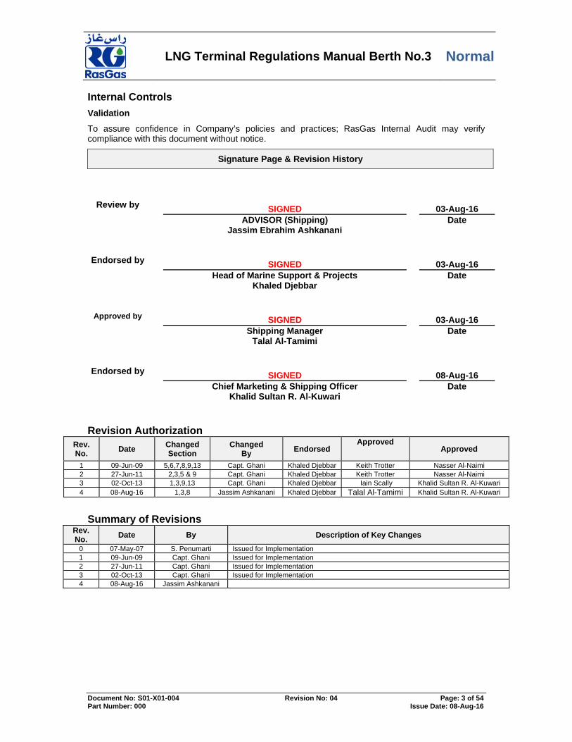
The maximum Trim permitted is 3.0 metres by the stern. The maximum List permitted is 3 degrees Port or Starboard The maximum Draft Permitted is 12.5 meters. Masters are advised to frequently check the correct function of the Breasting Fenders particularly during deballasting operations.
BREASTING FENDER
Defects and Deficiencies 8.6.2
Any defect or deficiency occurring in the LNGC’s manning, or equipment during the cargo handling operations must be immediately reported to the Terminal.
Repairs and Maintenance 8.6.3
See Port Regulations Section 3.2.34 and 3.2.41
ANY REPAIR OR MAINTENANCE WORK (EITHER COLD OR HOT) WHICH WOULD IMPAIR THE
SAFETY OF THE CARGO HANDLING OPERATIONS OR THE MANEUVERABILITY OF THE SHIP
ARE STRICTLY PROHIBITED UNLESS THE VESSEL HAS OBTAINED PRIOR WRITTEN
PERMISSION BY THE TERMINAL AND THE PORT AUTHORITY. Such exceptional authorization will not be granted during cargo handling operations. It will only been considered where unavoidable repair / breakdown occurs and may be conditional on the Master hiring sufficient tugs to move the LNGC as a contingency measure if so required. Should immobilization occur without prior approval from the Terminal or the Port Authority, the Terminal reserves the right to order tug(s) as above on the Master’s behalf for the vessel's account. The LNGC shall advise the Terminal of any intended maintenance planned during the vessels stay at the Terminal.
Crew Preparedness Readiness 8.6.4
At all times sufficient crew must remain ready on board the LNGC to ensure that the correct level of personnel are available to respond to any emergency situation that may occur.
Engine Readiness 8.6.5
Boilers, main engines, steering machinery and other equipment essential for maneuvering must be maintained so as to enable the LNGC to be unberthed under her own engine power at short notice in case of emergency.

LNG Terminal Regulations Manual Berth No.3 Normal
Document No: S01-X01-004 Revision No: 04 Page: 19 of 54 Part Number: 000 Issue Date: 08-Aug-16
Engine Safety 8.6.6
IN ORDER TO PREVENT MISOPERATION OF THE VESSELS MAIN ENGINE WHILST THE LOADING
ARMS ARE CONNECTED THE TERMINAL WILL REQUEST THAT THE VESSEL’S MAIN TURBINE
STEAM INLET V/V IS SEALED IN THE CLOSED POSITION PRIOR TO THE COMMENCEMENT OF
CONNECTION OF THE LOADING ARMS.
The Terminal will give formal permission to the vessel to remove the Turbine Steam Inlet Main Engine valves seal as soon as the loading arms are disconnected and clear of the vessel.
THE MASTER SHALL ENSURE THAT THE SHIP’S ENGINES ARE READY FOR A FULL RANGE OF
OPERATIONS BEFORE UNMOORING OPERATIONS ARE COMMENCED.
IT IS THE MASTERS RESPONSIBILITY TO ADVISE THE PILOT IF THERE IS ANY LIMITATION ON
THE RANGE OF USE OF THE SHIPS MAIN PROPULSION.
Environmental Discharge / Ballast Handling 8.7
Leaks and Pollution Prevention 8.7.1
See Port Regulations Section 6 & 9.
A vigilant look-out must be maintained by the LNGC’s crew in order to prevent and/or detect leaks or spillage during cargo handling or bunkering operations. The vessel shall immediately report any leaks or pollution to the terminal. The vessel shall immediately report any pollution incident to RasLaffan Port Control (In accordance with Ras Laffan Port Regulations section Section 3.2.64). Loading Arm connections to the LNGC will be leak tested with the terminal/LNGC nitrogen supply prior to the commencement of cargo loading operations. The pressure used for this leak test will be agreed between the LNGC and terminal and will be dependent upon the Maximum expected operating pressure for the planned operation. The maximum allowed pressure in the loading arm will be detailed in the Cargo Handling Agreement. (10.2 Appendix B: Cargo Handling Agreement). Any unused LNGC cargo and bunker connections must remain tightly closed and blanked. Whilst alongside the terminal the internal transfer of bunkers is not permitted. Deck scuppers, drain holes, and drip trays on the LNGC within the vicinity of any potential pollution area must be suitably plugged, if any accumulated water or effluent has to be drained off, the ship is to obtain permission from the terminal
Gas-Freeing 8.7.2
Gas-freeing of any LNGC’s tanks to atmosphere is strictly prohibited alongside the Berth.
Venting 8.7.3
Venting cargo vapor to the atmosphere is strictly prohibited. The Master is required to report to the Terminal and take all necessary action to prevent accidental venting. In the event of an emergency situation during which venting occurs, cargo handling operations will be immediately stopped.

LNG Terminal Regulations Manual Berth No.3 Normal
Document No: S01-X01-004 Revision No: 04 Page: 20 of 54 Part Number: 000 Issue Date: 08-Aug-16
Bilge Discharge 8.7.4
The discharge of bilge effluents, oil, or any mixture containing oil to sea is strictly prohibited.
Ballast Discharge 8.7.5
In accordance with Port Regulations section 3.2.8, “Masters are strongly advised to take all necessary precautions to minimize and control the introduction of unwanted aquatic organisms and pathogens from the vessel’s ballast water by adopting a ballast water exchange and sediment removal procedures in accordance with the relevant IMO Guidelines and Recommendations.” Should ballast water analysis indicate that the quality not conforming to that required by the Port Authority then ballast water discharge may not be permitted. Only clean segregated ballast is to be discharged within the port limits. Permission to deballast will be given from Ras Laffan Port Control only after the Port Authority has analysed a sample of the LNGC’s ballast. All LNGC’s ballast water other than that contained within Segregated Ballast Tanks must be retained on board.
Cargo Operations 8.8
Cargo Handling Agreement 8.8.1
The procedures for the intended cargo handling must be pre-planned, discussed and agreed by the Terminal Responsible Persons and the Vessel Responsible Person prior to the start of operations. 10.2 Appendix: Cargo handling Agreement
Control and Supervision of Operations 8.8.2
The Master shall ensure that at all times sufficient crew must remain on board his LNGC so as to ensure the proper handling of all cargo operations. All shipboard cargo handling operations must be competently and constantly supervised on board by a designated responsible person or persons so appointed by the Master. The person(s) so appointed shall maintain communications with the Master and the Terminal.
Ship / Shore Pre-Loading Meeting 8.8.3
A Pre-Loading Meeting will be held in the LNGC’s meeting room, in compliance with Section (6) of the “Ras-Laffan LNG Berth No.3 Cargo Handling Manual”, and with the Port Regulations. The Duty Loading Master (LM) & Marine Superintendent /Marine Advisor (if available) will attend this meeting so representing the Terminal. The designated responsible person(s) appointed by the Master to supervise the cargo handling operations on board the LNGC shall attend this meeting so representing the vessel. The following appendices will be given by the Terminal to the LNGC to be discussed, completed and agreed accordingly during this meeting:

LNG Terminal Regulations Manual Berth No.3 Normal
Document No: S01-X01-004 Revision No: 04 Page: 21 of 54 Part Number: 000 Issue Date: 08-Aug-16
ATTACHMENTS IN AGREEMENT
WITH REMARKS
10.1 Appendix A: Ship / Shore Safety Check List
LNGC/Terminal/Port
10.2 Appendix B: Cargo Handling Agreement LNGC/Terminal
10.3 Appendix C: Pre-Arrival Information LNGC/Terminal 10.4 Appendix D: Safety Declaration LNGC/Terminal 10.5 Appendix E: Communication Agreement LNGC/Terminal 10.6 Appendix F: Emergency Contacts LNGC/Terminal Information and document exchange between the LNGC and the Terminal is required, as defined in Section 1.7 VESSEL DOCUMENTATION.
ESD1 8.8.4
In order to minimize the potential hazard of a release of LNG, the LNG loading system is protected by two emergency shutdown systems: ESD-1 and ESD-2. ESD-1 allows the rapid shutdown of the loading pumps (or circulation pumps) operation during an emergency.
ESD-2 8.8.5
Ultimately uncouples the loading arms quickly when the arms are over extended. This emergency situation (e.g. Potential loading arm failure) is generally due to the LNGC moving outside the design envelope of the loading arms. The ESD-2 system consists of ESD-2A and ESD-2B. Simplified logic and sketches of ESD (ESD-1, ESD-2A and ESD-2B) can be found in appendices 13.11, 13.12 & 13.13.
Loading Arm Slew Angle Alarm and Trip setting
Loading Arm Apex Angle alarm and trip setting
Loading Arm ESD-2A ESD-2B Left Right Left Right A 13.5 deg 22.0 deg 17.5 deg 25.5 deg B 19.5 deg 10.5 deg 23.5 deg 14.5 deg C 16.5 deg 16.0 deg 20.5 deg 20.0 deg D 22.0 deg 22.5 deg 26.0 deg 25.5 deg
Loading Arm ESD-2A ESD-2B A 109 deg 115 deg B 109 deg 115 deg C 109 deg 115 deg D 109 deg 115 deg
Liquid and Vapour Arms Connection 8.8.6
LNG loading will normally be carried out through three liquid loading arms on the Berth, unless previously agreed between the LNGC and the Terminal during the Pre-Loading Meeting. No other transferring device will be accepted for cargo handling operations.

LNG Terminal Regulations Manual Berth No.3 Normal
Document No: S01-X01-004 Revision No: 04 Page: 22 of 54 Part Number: 000 Issue Date: 08-Aug-16
Steam ships are encouraged to burn gas alongside but prior authorization has to be obtained from RasGas Marketing & Shipping group. Boil-off vapor generated in LNGC’s cargo tanks will be sent back to shore through the vapor return arm, which will be connected prior to the liquid loading arms. The Master is required to ensure that the LNGC’s manifolds are ready for connection prior to the completion of berthing and that the LNGC’s manifold water curtain has been established before the Terminal maneuvers the arms on board. Liquid loading arms and Vapor return arm will be connected by the Terminal upon LNGC’s confirmation of readiness, and after the Terminal is satisfied that the LNGC is in compliance with the requirements of the Ship-Shore Safety Checklist. The liquid and vapor arms will be purged with nitrogen (Oxygen Content < 1% by Volume) by the Terminal after connection. The Master is required to provide assistance from his crew on LNGC’s manifold for communication purposes with the Terminal during arms maneuver and connection.
Cargo Measurements / CTMS 8.8.7
The Master shall ensure that the cargo measurements are conducted in compliance with the “Ras Laffan LNG Berth No. 3 Cargo Handling Manual” & “CTMS Manual”. The Terminal reserves the right to witness the cargo measurements on board the LNGC in accordance with the particular SPA or cargo memorandum.
Jetty Boil Off Gas Recovery / Vapour return to Shore and Gas Burning 8.8.8
Boil-off vapour generated in LNGC’s cargo tanks shall be directed to shore using HD compressor/s to be recovered by JBOG RCOVERY PLANT as soon as parameter being achieved (Ref. Attachment 13.16). In line with State of Qatar initiative/commitment to reduce as much as possible release of vapour emission to the atmosphere and care towards the environment. During non-recovery period, as far as practicable the BOG generated shall be handled by the LNGC either on GAS ONLY MODE or DUAL Fuel & Gas Mode whilst concurrently sending vapour to shore to be flared, on the understanding that the Terminal will permanently maintain the flare operation. The cargo handling operations will be immediately stopped by the Terminal when for any reason the boil-off vapor is not being properly flared.
Cargo Handling Equipment Machinery Condition 8.8.9
The Master is required to ensure that all LNGC’s equipment used in cargo handling operations is properly manned and maintained in a satisfactory manner throughout the cargo handling operations. Any deficiency that may impair the safety or the efficiency of the cargo handling operations must be immediately reported to the Terminal.
Manifold Drip Tray 8.8.10
In line with SIGTTO recommendation, manifold drip trays for LNG transfer are to be kept as dry as reasonably practical. Water should not be introduced deliberately, or allowed to accumulate in rain. Manifold area is to be restricted during cargo transfer operations. If required entry for local pressure gauge readings, then this should be done as quick as possible with extreme caution.

LNG Terminal Regulations Manual Berth No.3 Normal
Document No: S01-X01-004 Revision No: 04 Page: 23 of 54 Part Number: 000 Issue Date: 08-Aug-16
Loading Start-up / Stoppage 8.8.11
All loading start-up and stoppage of the cargo handling operations will be at the Master’s discretion. The Terminal reserves the right to delay the loading start-up or to require the loading to be stopped at any time due to Terminal operational requirements. The Master is required to provide reasonable notice to the Terminal for any changes or requirements that may affect the cargo handling operations. This does not change the Master’s authority to deal with emergency situations. The Terminal will provide reasonable notice to the Master for any changes or requirements that may affect the cargo handling operations.
Loading Rates 8.8.12
The Master and the Terminal will agree to the maximum loading rate at the pre loading meeting. The agreed loading rate will be noted on the cargo handling agreement. The Master and Terminal will monitor the loading rates throughout all stages of loading but particularly during the initial stages of cargo handling operations such that the need to flare excess return is minimized. The loading rates changes shall be at the Master’s or the Terminals discretion. The maximum loading rate for this terminal is 10,400m3/hr.
Liquid and Vapor Arms Disconnection 8.8.13
The liquid and vapor arms will be purged with nitrogen normally supplied by the terminal prior to disconnection, which will not be authorized until samples taken from the loading arms show a gas concentration of less than 1% by volume. Loading Master and Loading operator will direct the whole of Loading Arms Draining & Purging and disconnection operations Draining & Purging Operations of the loading arms is normally carried out in a sequence determined by the Loading Master and Loading operator arm by arm
All personnel attending to these operations must wear appropriate PPE, including suitable eye goggles and safety shoes with anti-static soles. During Draining Operation, only spot checks are allowed from either the ship’s manifold or loading arm drain valve in order to determine the presence of LNG. (Ref. appended diagram)

LNG Terminal Regulations Manual Berth No.3 Normal
Document No: S01-X01-004 Revision No: 04 Page: 24 of 54 Part Number: 000 Issue Date: 08-Aug-16
Stop N2 once completion of this draining apex to ship and depressurize to shore
N2
First drain apex to ship side
TO CARGO TANK
SPOT CHECK
Second drain apex to shore side
Main Liquid Header
Apex style 40
Apex style 40
Bucket
Drain valve
DSV
COUPLER
Inboard Outboard
DBV
Cool down valve
ESDV
ESDV
Open to drain apex to shore side
Drain to drum
Outboard Inboard
N2
DBV
COUPLER
Open cool down valve if any trapped pressure
Cool down valve

LNG Terminal Regulations Manual Berth No.3 Normal
Document No: S01-X01-004 Revision No: 04 Page: 25 of 54 Part Number: 000 Issue Date: 08-Aug-16
The Master is required to ensure that the LNGC’s manifolds and cargo lines are ready for purging, and disconnecting operations. Personnel responsible to conduct the sampling are encouraged to use the ships earthing plates whenever fitted prior to access the manifolds platform. Loading Master and Loading operator ensures that Ship conducts continuous checks on hydrocarbons content around the manifold area by means of portable explosimeters.
THE MASTER SHALL ENSURE THAT STEPS ARE TAKEN TO PREVENT MIS-OPERATION OF
VESSEL ESD/MANIFOLD VALVES THAT MAY RESULT IN A RELEASE OF LNG OR VAPOUR
THROUGH THE MANIFOLD AT THE TIME OF DISCONNECTION.
Ensure that each arm is purged for at least 15 minutes before the first sampling can be done.
Gas portable detectors used for sampling should be certified & calibrated, suitably designed to measure gas concentrations in oxygen deficient atmospheres; they should not be of a Gas Combustible type. Purging operation is only completed when the gas concentration falls below 1% by volume. Ship gas Meter / Terminal’s Infra Red Gas Meter is allowed to be used for measurements and will deliver final authorization as to disconnect the arm. The liquid and vapor arms will be disconnected and stowed one by one by the Terminal. The Master is required to provide assistance from his crew on the LNGC’s manifold for communication purposes with the Terminal during arm draining/purging and disconnection.
The Master has the sole responsibility for the safety of his crew.
The Master should ensure that all crew members remain at a safe distance from the loading arms whilst they are being maneuvered by the Terminal.
Ship / Shore Post – Loading Meeting 8.8.14
A post-loading meeting will be held in the LNGC’s meeting room, in compliance with the section (6.21) of the “RasLaffan LNG Berth No.3 Cargo Handling Manual”. The Duty Loading Master (LM) and Marine Superintendent /Marine Advisor (if available) will attend this meeting so representing the Terminal. The designated responsible person(s) appointed by the Master to supervise the cargo handling operations on board the LNGC shall attend this meeting so representing the LNGC.
Feedback Form 9.0
Master shall be provided with a Feedback form by the Loading Master (LM) during the Pre-Loading meeting. LM is required to highlight to Master of any shortcomings, defects thereof during cargo operations both by ship or shore. Details shall be agreed and noted in the Feedback form. Submission of the form is via email to the designated person upon departure of the vessel.

LNG Terminal Regulations Manual Berth No.3 Normal
Document No: S01-X01-004 Revision No: 04 Page: 26 of 54 Part Number: 000 Issue Date: 08-Aug-16
Training and Support 10.0
Terminal personnel (Offsites) continuous ongoing on job training inclusive of Q-top & LM Training Program. Supervised by Offsite Supervisors and LM / Marine Superintendent / Marine Advisor for shipboard activities.
Verification Measurement 11.0
Assessment within Q-top & LM Training Manual. Continuous Reporting within SAP of Ship/Shore Defects or discrepancies.
Feedback and Continual improvement 12.0
Feedback from vessel via communication with Shipping Dept. shall be compiled and assessed for further improvement. The Manual shall be reviewed at least every 2 years to assess its relevancy to current circumstances.
Attachments 13.0
Attachment A Ship/Shore Safety Check-List
Attachment B Cargo Handling Agreement
Attachment C Pre-Arrival Information
Attachment D Safety Declaration
Attachment E Communication Agreement
Attachment F Emergency Contacts
Attachment G Adverse Weather – Terminal Operating Policy
Attachment H Loading Arm – Operating Envelope Berth No.3
Attachment I Mooring Diagram – LNG Berth No.3
Attachment J Terminal Alarms – Berth No.3
Attachment K ESD1 LNG Berth No.3
Attachment L ESD 2A
Attachment M ESD 2B LNG Berth No.3
Attachment N Compatibility Information
Attachment O Feedback Form
Attachment P JBOG (Jetty Boil Off Gas Recovery)
LNG Terminal Regulations Manual Berth No.3 Normal
Document No: S01-X01-004 Revision No: 04 Page: 27 of 54 Part Number: 000 Issue Date: 08-Aug-16
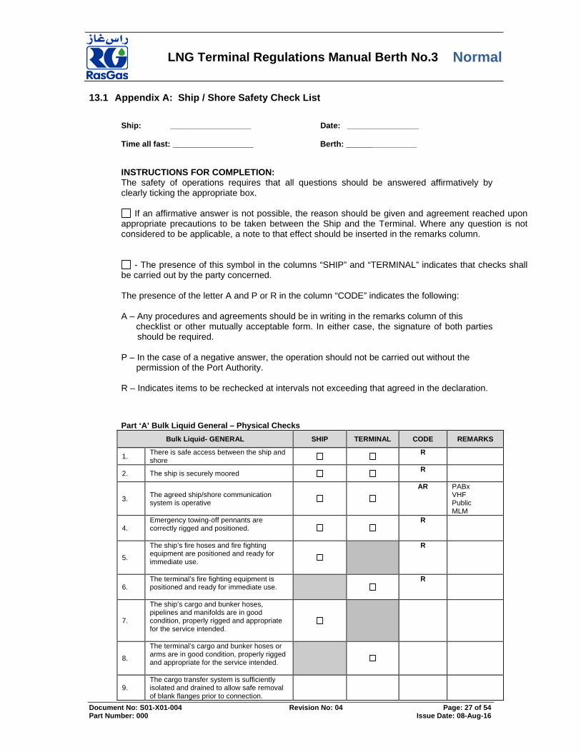
Appendix A: Ship / Shore Safety Check List 13.1
Ship: __________________ Date: ________________
Time all fast: __________________ Berth: _________________
INSTRUCTIONS FOR COMPLETION: The safety of operations requires that all questions should be answered affirmatively by clearly ticking the appropriate box.
If an affirmative answer is not possible, the reason should be given and agreement reached upon appropriate precautions to be taken between the Ship and the Terminal. Where any question is not considered to be applicable, a note to that effect should be inserted in the remarks column.
- The presence of this symbol in the columns “SHIP” and “TERMINAL” indicates that checks shall be carried out by the party concerned. The presence of the letter A and P or R in the column “CODE” indicates the following: A – Any procedures and agreements should be in writing in the remarks column of this checklist or other mutually acceptable form. In either case, the signature of both parties
should be required. P – In the case of a negative answer, the operation should not be carried out without the permission of the Port Authority. R – Indicates items to be rechecked at intervals not exceeding that agreed in the declaration.
Part ‘A’ Bulk Liquid General – Physical Checks
Bulk Liquid- GENERAL SHIP TERMINAL CODE REMARKS
1. There is safe access between the ship and shore
R
2. The ship is securely moored R
3. The agreed ship/shore communication system is operative
AR PABx VHF Public MLM
4. Emergency towing-off pennants are correctly rigged and positioned.
R
5.
The ship’s fire hoses and fire fighting equipment are positioned and ready for immediate use.
R
6. The terminal’s fire fighting equipment is positioned and ready for immediate use.
R
7.
The ship’s cargo and bunker hoses, pipelines and manifolds are in good condition, properly rigged and appropriate for the service intended.
8.
The terminal’s cargo and bunker hoses or arms are in good condition, properly rigged and appropriate for the service intended.
9. The cargo transfer system is sufficiently isolated and drained to allow safe removal of blank flanges prior to connection.

LNG Terminal Regulations Manual Berth No.3 Normal
Document No: S01-X01-004 Revision No: 04 Page: 28 of 54 Part Number: 000 Issue Date: 08-Aug-16
10.
Scuppers and save-alls on board are effectively plugged and drip trays are in position and empty.
R
11. Temporarily removed scupper plugs will be constantly monitored.
R
12. Shore spill containment and sumps are correctly managed.
R
13.
The ship’s unused cargo and bunker connections are properly secured with blank flanges fully bolted.
14.
The terminal’s unused cargo and bunker connections are properly secured with blank flanges fully bolted.
15.
All cargo, ballast and bunker tank lids are closed
16. Sea and overboard discharge valves, when not in use, are closed and visibly secured.
17.
All external doors, ports and windows in the accommodation, stores and machinery spaces are closed. Engine room vents may be open.
R
18. The ship’s emergency fire control plans are located externally.
Onshore + Offshore Gangway
Part ‘B’ Bulk Liquid General – Verbal Verification
19. The ship is ready to move under its own power
PR ER Warm Up
__Hrs
20.
There is an effective deck watch in attendance on board and adequate supervision of operations on the ship and in the terminal.
R
21. There are sufficient personnel on board and ashore to deal with an emergency
R
22. The procedures for cargo, bunker and ballast handling have been agreed
AR
23.
The emergency signal and shutdown procedures to be used by the ship and shore have been explained and understood.
A
24.
The hazards associated with LNG handling been identified and understood and the Material Safety Data Sheet (MSDS) for the cargo transfer have been exchanged where requested.
PR
25. An International Shore Fire Connection has been provided.
26. The vapour return line is connected AR
27. The vapour return line operating parameters been agreed.
AR
28. Independent high level alarms are operational and have been tested.
AR
29. Adequate insulating means are in place in

LNG Terminal Regulations Manual Berth No.3 Normal
Document No: S01-X01-004 Revision No: 04 Page: 29 of 54 Part Number: 000 Issue Date: 08-Aug-16
the ship/shore connection
AR
30. Smoking rooms have been identified and smoking requirements are being observed
AR
Nominated smoking room:
31. Naked light regulations are being observed.
AR
32. Unless intrinsically safe, all mobile phones / pagers are switched off when on deck.
AR
33. Hand torches ( flashlights) are of an approved type.
34.
Fixed VHF/UHF transceivers and AIS equipment are on the correct power mode or switched off.
A
35. Portable VHF/UHF transceivers are of an approved type.
36. The ship’s main radio transmitter aerials are earthed and radars are switched off.
37. Electric cables to portable electrical equipment within the hazardous area are disconnected from power
38. Window type air conditioning units are disconnected.
39.
Positive pressure is being maintained inside the accommodation, and air conditioning intakes, which may permit the entry of cargo vapours, are closed.
40.
Measures have been taken to ensure sufficient mechanical ventilation in the compressor room.
R
41. There is provision for an emergency escape
42. The maximum wind and swell criteria for operations have been agreed
A Stop: Disconnect: Unberth:
43.
Security protocols have been agreed between the Ship Security Officer and the Port Facility Security Officer, if appropriate
A
Part ‘C’ Bulk Liquefied Gases - Verbal Verification
44. The water spray system is ready for immediate use.
45.
There is sufficient suitable protective equipment ( including self-contained breathing apparatus ) and protective clothing ready for immediate use.
46. Hold and inter-barrier spaces are properly inerted or filled with dry air, as required.
47. All remote control valves are in working order.
48.
The required cargo pumps and compressors are in good order, and the maximum working pressures have been greed between ship and shore.
A
49. Re-Liquefaction or boil off control equipment is in good operational order.
A

LNG Terminal Regulations Manual Berth No.3 Normal
Document No: S01-X01-004 Revision No: 04 Page: 30 of 54 Part Number: 000 Issue Date: 08-Aug-16
50.
The gas detection equipment has been properly set for the cargo , is calibrated, has been tested and inspected and is in good order.
51. Cargo system gauges and alarms are correctly set and in good order.
52. Emergency Shutdown systems have been tested and are working properly.
53. Ship and shore have informed each other of the closing rate of ESD valves, automatic valves or similar devices.
A Ship: Shore:
54.
Information has been exchanged between ship and shore on the maximum/minimum temperatures/pressures of the cargo to be handled.
A
55. Cargo tanks are protected against inadvertent overfilling at all times while any cargo operations are in progress.
56.
The compressor room is properly ventilated, the electrical motor room is properly pressurized and the alarm system is working.
57. Cargo tank relief valves are set correctly and actual relief valve settings are clearly and visibly displayed.
Tank No. 1 ........................................ Tank No. 2 ........................................ Tank No. 3 ........................................ Tank No. 4 ........................................ Tank No. 5 .......................................
Declaration
We the undersigned have checked, where appropriate jointly, the items on this checklist and have satisfied ourselves
that the entries we have made are correct to the best of our knowledge.
We have also made arrangements to carry out repetitive checks as necessary and agreed that those items with the
letter “R” in the column “Code’ should be re-checked at intervals not exceeding 4 hours.
For Ship
For Shore
Name :
Name :
Rank :
Position :
Signature
Signature
Date: Time:
Date: Time:
‘R’ Items Re-Check:
Date/ Time:
For Ship
For Terminal
LNG Terminal Regulations Manual Berth No.3 Normal
Document No: S01-X01-004 Revision No: 04 Page: 31 of 54 Part Number: 000 Issue Date: 08-Aug-16
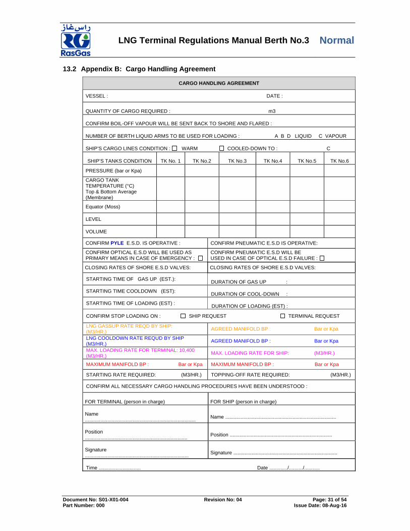
Appendix B: Cargo Handling Agreement 13.2
CARGO HANDLING AGREEMENT
VESSEL : DATE :
QUANTITY OF CARGO REQUIRED : m3 CONFIRM BOIL-OFF VAPOUR WILL BE SENT BACK TO SHORE AND FLARED : NUMBER OF BERTH LIQUID ARMS TO BE USED FOR LOADING : A B D LIQUID C VAPOUR SHIP’S CARGO LINES CONDITION : WARM COOLED-DOWN TO : C
SHIP’S TANKS CONDITION
TK No. 1
TK No.2
TK No.3
TK No.4
TK No.5
TK No.6
PRESSURE (bar or Kpa)
CARGO TANK TEMPERATURE (°C) Top & Bottom Average (Membrane)
Equator (Moss)
LEVEL
VOLUME
CONFIRM PYLE E.S.D. IS OPERATIVE : CONFIRM PNEUMATIC E.S.D IS OPERATIVE:
CONFIRM OPTICAL E.S.D WILL BE USED AS PRIMARY MEANS IN CASE OF EMERGENCY :
CONFIRM PNEUMATIC E.S.D WILL BE USED IN CASE OF OPTICAL E.S.D FAILURE :
CLOSING RATES OF SHORE E.S.D VALVES: CLOSING RATES OF SHORE E.S.D VALVES:
STARTING TIME OF GAS UP (EST.): DURATION OF GAS UP :
STARTING TIME COOLDOWN (EST): DURATION OF COOL-DOWN :
STARTING TIME OF LOADING (EST) : DURATION OF LOADING (EST) :
CONFIRM STOP LOADING ON : SHIP REQUEST TERMINAL REQUEST
LNG GASSUP RATE REQD BY SHIP: (M3/HR.)
AGREED MANIFOLD BP : Bar or Kpa
LNG COOLDOWN RATE REQUD BY SHIP (M3/HR.)
AGREED MANIFOLD BP : Bar or Kpa
MAX. LOADING RATE FOR TERMINAL: 10,400 (M3/HR.)
MAX. LOADING RATE FOR SHIP: (M3/HR.)
MAXIMUM MANIFOLD BP : Bar or Kpa MAXIMUM MANIFOLD BP : Bar or Kpa
STARTING RATE REQUIRED: (M3/HR.) TOPPING-OFF RATE REQUIRED: (M3/HR.)
CONFIRM ALL NECESSARY CARGO HANDLING PROCEDURES HAVE BEEN UNDERSTOOD :
FOR TERMINAL (person in charge)
FOR SHIP (person in charge)
Name ...............................................................................
Name ...............................................................................
Position .........................................................................
Position .........................................................................
Signature ..........................................................................
Signature ..........................................................................
Time .............................. Date ............./........../...........

LNG Terminal Regulations Manual Berth No.3 Normal
Document No: S01-X01-004 Revision No: 04 Page: 32 of 54 Part Number: 000 Issue Date: 08-Aug-16
Appendix C: Pre-Arrival Information 13.3
1 SHIP’S NAME AND CALL SIGN?
2 PORT OF REGISTRY:
3 NAME OF MASTER:
4 GRT/NRT:
5 ARRIVAL DISPLACEMENT:
6 SUMMER DEADWEIGHT (METRIC TONNES)
7 LENGTH OVER ALL (m) :
8 DRAFT FORE AND AFT ON ARRIVAL (m):
9 DRAFT FORE AND AFT ON SAILING (m):
10 ADVISE QUANTITY OF CLEAN SEGREGATED BALLAST TO BE DISCHARGED AT THIS PORT
11 ADVISE ANY VESSEL DEFECT AFFECTING CARGO OPERATIONS OR MANEUVERING / MOORING ABILITY.
12 CONFIRM P&I CLUB NAME AND VALIDITY:
13 CONFIRM POLLUTION COVER
14 LAST 3 PORTS OF CALL
15 N/A
16 DOES VESSEL HAVE FULLY OPERATIONAL IG SYSTEM?
17 CONDITION OF TANKS ON ARRIVAL
18 N/A
19 IS IG SYSTEM OPERATIONAL
20 ARE SMOKE/FIRE DETECTION AND FIXED FIRE EXTINGUISHING SYSTEMS FULLY OPERATIONAL?
21 AMOUNT AND GRADE OF CARGO REQUIRED:
22 SIZE, RATING AND STANDARDS OF CARGO MANIFOLD CONNECTION?
23 DISTANCE OF CENTER MANIFOLD FROM THE BOW AND DISTANCE OF SPRINGLINE FAIRLEADS FROM THE CENTRE OF THE MANIFOLDS
24 HEIGHT OF MANIFOLD ABOVE THE KEEL:
25 DISTANCE BETWEEN MANIFOLD FLANGES CENTERS:
26 DISTANCE OF MANIFOLD FROM SHIP’S SIDE:
27 DISTANCE FROM MANIFOLD FACE TO FIRST FULL RESTRAINING BRACKET:
28 MAXIMUM LOADING RATE:
29 ANTICIPATED LOADING TIME:
30 CONFIRM CARGO TRNSFER EMERGENCY STOPS FULLY OPERATIONAL AND DATE OF LAST TEST
31 CONFIRM TANK HIGH LEVEL AND PRESSURE ALARMS OPERATIONAL:
32 CONFIRM THAT REMOTELY OPERATED MANIFOLD VALVES HAVE BEEN OPERATED THROUGH A COMPLETE OPEN/CLOSED CYCLE, ENSURE CORRECT FUNCTIONING AND ADVISE VALVE TYPE AND ACTUAL CLOSING TIME.
33 BOTH ANCHORS TO BE CLEARED AWAY AND MAIN ENGINE TESTED ASTERN, BOW THRUSTER TESTED BEFORE PILOT BOARDS
34 INMARSAT No. TELEX No. TELEFAX No.
35 DOES VESSEL COMPLY WITH ISM CODE
36 VALIDITY OF ISM DOC/SMC AND ISSUING AUTHORITY
PRE-ARRIVAL INFORMATION

LNG Terminal Regulations Manual Berth No.3 Normal
Document No: S01-X01-004 Revision No: 04 Page: 33 of 54 Part Number: 000 Issue Date: 08-Aug-16
Appendix D: Safety Declaration 13.4
The Master:………………………….
Ship;………………………………….
Berth: No.3.
Dear Sir,
Responsibility for the safe conduct of operations whilst your ship is at this terminal rests jointly with you as Master of the ship, and with the responsible terminal representative. We wish, therefore, before operations start, to seek your full cooperation and understanding on the safety requirements set out in the Ship/Shore Safety Checklist which are based on safe practices widely accepted by the oil and tanker industries (refer to Attachment 13.01)
We expect you and all under your command to adhere strictly to these requirements throughout your stay alongside this terminal and we, for our part, will ensure that our personnel do likewise and cooperate fully with you in the mutual interest of safe and efficient operations.
Before the start of operations, and from time to time thereafter, for our mutual safety, a member of the terminal staff, where appropriate together with a responsible officer, will make a routine inspection of your ship to ensure that the questions on the Ship/Shore Safety Checklist can be answered on the affirmative. Where corrective action is needed we will not agree to operations commencing, or should they have been started, we will require them to be stopped.
Similarly, if you consider safety is endangered by any action on the part of our staff or by any equipment under our control you should demand immediate cessation of operations.
THERE CAN BE NO COMPROMISE WITH SAFETY
Please acknowledge receipt of this letter by countersigning and returning the attached copy. Signed…………………………….. (Terminal Representative) Terminal Representative on duty is…………………………………………………………. Position or Title………………………………………………………………………………… Telephone Number:…………………………………………………………………………… UHF/VHF Channel:…………………………………………………………………………….. Signed:…………………………………… Date:…………………………………….. (Master) Time:…………………………………….. SS/MV:…………………………………….
Appendix E: Communication Agreement 13.5
A PYLE NATIONAL LINK HAS BEEN CONNECTED TO YOUR SHIP. IT WILL ENABLE THE

LNG Terminal Regulations Manual Berth No.3 Normal
Document No: S01-X01-004 Revision No: 04 Page: 34 of 54 Part Number: 000 Issue Date: 08-Aug-16
FOLLOWING MEANS OF COMMUNICATIONS:
E.S.D FROM THE SHIP (emergency shut-down)
uni-directional. Can be activated at any time from the Ship in case of emergency. Inform Terminal as far as possible before use. See appendix (14.3).
E.S.D FROM TERMINAL (emergency shut-down)
uni-directional. Can be activated at any time from the Terminal in case of emergency. Inform Ship as far as possible before use. See appendix (14.3).
HOT LINE bi-directional. To contact directly the Terminal Superintendent in case of emergency.
TERMINAL INTERNAL LINE
bi-directional. To exchange normal information between Ship and Marine Terminal Building during cargo handling operations.
PUBLIC LINE
bi-directional. Enable the Ship to use the Qatari national telephone network, “Q-TEL”.
MOORING LINE TENSION DATA
uni-directional. For the Ship to receive information on the tension of each mooring line.
A PNEUMATIC LINK HAS BEEN CONNECTED TO YOUR SHIP. IT WILL ENABLE THE
FOLLOWING MEANS OF COMMUNICATION : E.S.D FROM
THE SHIP (emergency shut-down)
uni-directional. Can be activated at any time from the Ship in case of emergency. Inform Terminal as far as possible before use. See appendix (14.3).
E.S.D FROM TERMINAL (emergency shut-down)
uni-directional. Can be activated at any time from the Terminal in case of emergency. Inform Ship as far as possible before use. see appendix (14.3).
In the event that your vessel does not have a fixed U.H.F. radio system compatible with the Terminal a PORTABLE U.H.F RADIO will be provided to your ship. IT WILL ENABLE

LNG Terminal Regulations Manual Berth No.3 Normal
Document No: S01-X01-004 Revision No: 04 Page: 35 of 54 Part Number: 000 Issue Date: 08-Aug-16
THE FOLLOWING MEANS OF COMMUNICATIONS :
MTB Loading Master (LM)
FOR SHIP (person in charge)
FOR TERMINAL (person in charge)
Name...................................................
Name................................................................
Position................................................ Position.............................................................
Signature ……..................................... Signature.........................................................
Time.......................
Date ............../............../..............
Appendix F: Emergency Contacts 13.6

LNG Terminal Regulations Manual Berth No.3 Normal
Document No: S01-X01-004 Revision No: 04 Page: 36 of 54 Part Number: 000 Issue Date: 08-Aug-16
EMERGENCY CONTACTS MTB Via: HOTLINE
2970 or 2969
VHF P04 / P05
If no response from MTB Call following Nos from the Terminal Telephone:
8910 Shift Superintendent
8999 ECRO PORT CONTROL FOR DEBALLASTING ( 9 ) 44733200 AGENT ( 9 ) 55509464 / 55816566 LOADING MASTER ( 9 ) 55817310 RG VHF Frequencies: P4 157.800 MHz (Jetty No.3) P5 158.275 MHz ( Jetty No.3)
Appendix G: Adverse Weather – Terminal Operating Policy 13.7

LNG Terminal Regulations Manual Berth No.3 Normal
Document No: S01-X01-004 Revision No: 04 Page: 37 of 54 Part Number: 000 Issue Date: 08-Aug-16
Condition Operation Action Comments
Wind < 28kts
Connection Loading Disconnection
Continuous operations
Normal operating Conditions
Wind 28kts to 35kts
Connection Loading Disconnection
Communication Monitor Wx forecasts Monitor prevailing Wx &
wind speed ex Port Control.
Extra Vigilance Close observation of
vessel position. Close visual
observation of mooring line integrity.
Close monitoring of mooring line tension data.
Close visual observation of vessel movement due sea/swell inside harbour.
Decision to suspend loading and commence disconnection can be taken at any time by Terminal in consultation with Master. The decision to suspend loading and disconnect shall be made on the basis of all information available to the terminal concerning: Prevailing Wx. Forecasted Wx. Anticipated rate of increase of
wind speed. Condition of mooring system. Position & movement of vessel Time to de-ice/drain/purge &
disconnect loading arms. Time to complete loading vs risk
to vessel remaining alongside /risk of disconnection /reconnection.
See following guidelines / check list.
(To be developed) Wind 35kts
Disconnection
Stop loading Drain loading arms Purge loading arms Disconnect Loading arms. Raise shore gangway clear of vessel handrail following disembarkation of shore staff.
Loading arms cannot be manouevered safely when steady mean wind speed >40knots. Shore gangway to be raised to prevent damage in case of vessel movement. Fibre Optic Cable or Electric comms cable to remain connected so that vessel may receive Mooring Line Tension Data.
Wind > 33Kts
Berthing
Berthing operations suspended
Ras Laffan Port Regulations
Wind 38kt
Unberthing
Unberthing operations suspended
Ras Laffan Port Regulations
Any wind speed
Disconnection
Terminal reserves the right to suspend operations and disconnect loading arms in the event of detioriating weather. Terminal reserves the right to postpone connection of loading arms until the wind speed is <35kts.
Condition Operation Action Comments

LNG Terminal Regulations Manual Berth No.3 Normal
Document No: S01-X01-004 Revision No: 04 Page: 38 of 54 Part Number: 000 Issue Date: 08-Aug-16
Wind >40kts
Tug(s) pushing
Optional Tug assistance
Request by Master or Marine Supt in
consultation with duty Pilot.
In the event that the wind is from the
direction of the jetty, or if the Terminal /
Master / Port assess that the vessel
mooring pattern may be compromised
Decision to utilize tug(s) shall be on
the basis of prevailing and forecasted
wind speed & direction and any other
factors that may be affecting the
mooring pattern.
Tugs are not to be utilized if loading
arms are connected unless in an
emergency such that vessel
breakaway is likely due to
compromised mooring pattern.
Berth mooring designed for beam winds of 60kts ie OCIMF Standard. Project Vessel mooring systems designed to OCIMF standard. OPTIMOOR mooring analysis completed for each class of LNG vessel prior to first arrival RasLaffan
Lightening
Suspend loading Suspend disconnection procedures Suspend connection
Stop loading close all ship tank valves and vents. Manage cargo tank pressures to prevent inadvertent venting.
If lightening in immediate vicinity of Ras Laffan Harbour.
List 3 Draft12.5m
Trim3.0m
Suspend Loading
Stop Loading close all loading valves. Take corrective action.
*Average (Steady) wind speed over a 10minute period - as measured in Ras Laffan Port Control Tower. **Tug may constitute an uncontrolled source of ignition.

LNG Terminal Regulations Manual Berth No.3 Normal
Document No: S01-X01-004 Revision No: 04 Page: 39 of 54 Part Number: 000 Issue Date: 08-Aug-16

LNG Terminal Regulations Manual Berth No.3 Normal
Document No: S01-X01-004 Revision No: 04 Page: 40 of 54 Part Number: 000 Issue Date: 08-Aug-16
Appendix H: Loading Arm – Operating Envelope Berth 13.8
Item (m)
Working Range of Loading Arm above Datum
High ① EL + 27.270
Low ② EL + 14.000
Tide Level
High ③ EL +0.970 Low ④ EL -0.760
Heave & List High & Low ±0.000
Loading Arm Length
Inboard Arm ⑤ 7.920 Outboard Arm ⑥ 8.530
Distance
⑦ 3.150 ⑧ 3.000 ⑨ 3.000 above Datum ⑩ EL + 14.700

LNG Terminal Regulations Manual Berth No.3 Normal
Document No: S01-X01-004 Revision No: 04 Page: 41 of 54 Part Number: 000 Issue Date: 08-Aug-16
Appendix I: Mooring Diagram – LNG Berth No.3 13.9

LNG Terminal Regulations Manual Berth No.3 Normal
Document No: S01-X01-004 Revision No: 04 Page: 42 of 54 Part Number: 000 Issue Date: 08-Aug-16
Appendix I: Terminal Alarms – Berth No.3 13.10
AUDIBLE ALARMS (TIMER DELAY) It was agreed that continuous sounding of the audible alarm could, after a certain period of time, interfere with communication and/or become distracting to personnel. As such, it was agreed that the initiated audible alarm (i.e. General Alarm or Evacuation Alarm) would be sounded for a three (3) minute period, after which time the audible portion of the alarm would automatically be silenced, however the appropriate lights would continue to flash. If it is deemed appropriate or necessary to reinitiate the audible part of the alarm, this could be done, thereby starting an additional three (3) minute audible alarm period. It was agreed that the audible tone for the ‘All Clear’ signal would sound for a period of two (2) minutes. AUDIBLE ALARMS (PUBLIC ADDRESS ANNOUNCEMENTS) It was agreed that the ‘All Clear’ signal would be supplemented by a Public Address (PA) announcement after conclusion of the two (2) minute tone. It was agreed that the capability should exist to make an announcement during an audible alarm if desired. It was therefore agreed that when such a PA announcement is made, that the audible alarm will be automatically attenuated by 10 decibels (dB).
SUMMARY OF AGREED AUDIBLE / VISUAL ALARMS
Alarm type Audible Visual
General Alarm ‘Sawtooth’
700 to 1100 Hz 1 second period
Red flashing (at high noise and muster areas)
Evacuation Alarm ‘Howl’
600 to 880 Hz 3 second period
Blue flashing (at muster areas only)
All Clear ‘Steady Tone’
1000 Hz plus PA announcement
None

LNG Terminal Regulations Manual Berth No.3 Normal
Document No: S01-X01-004 Revision No: 04 Page: 43 of 54 Part Number: 000 Issue Date: 08-Aug-16
Appendix J: E.S.D 1 LNG Berth No.3 13.11
ESD - 1 (71UZ-3110) ESD-1 allows the rapid shutdown of the loading pumps (or circulation pumps) operation during an emergency. A Ship to Shore optical fiber link conveys the shutdown signal to and from the LNGC. The ESD-1 signal closes two pneumatic actuated 26” ESD valves on the LNG Jetty in about 15 seconds. The ESD-1 signal closes two Hydraulic actuated 30” ESD valves at the plant fence in about 60 seconds. The ESD-1 sends a signal to the LNGC to close the LNGC’s manifold valves (25 sec) to be closed. Summary of all ESDV Closing times is shown as follows:
Valve Location Closing time (sec)
30” 71ESDV-3110K Tankage area fence 60
30” 71ESDV-3110J Tankage area fence 60
24” 71ESDV-3110M 70m from RasGas Jetty head 15
24” 71ESDV-3110P 70m from RasGas Jetty head 15
24” 71ESDV-3120 Jetty Drain Tank inlet 10 (open)
DBV Loading arm 5
Note: 71ESDV-120 will open only for 60 sec when ESD2A is activated. After 60 sec it will close.
Manual Initiation
71HZ-3110M (Mounted on Marine Terminal Building (MTB))
71HS-3180 Vessel Initiated
Automatic Initiation (71UZ-3110)
ESD-2A (71UZ-3121)
ESD-2B (71UZ-3120) (Via ESD-2A)
Low Low LNG Storage Tank pressure (71 PALL3103 A/B and 71PALL5103A)
High High liquid level in LNG Jetty Surge/Blowdown Drum (71- V052). (71LAHH3115)
89-Y054V001 LNG SPILL BASIN TEMP. LOW (2oo3 VOTING) 89TT-0097A/B/C

LNG Terminal Regulations Manual Berth No.3 Normal
Document No: S01-X01-004 Revision No: 04 Page: 44 of 54 Part Number: 000 Issue Date: 08-Aug-16
Appendix K: E.S.D 2A (71UZ-3121) 13.12
ESD 2A is a sequence of events that prepares the loading arms for emergency disconnection utilizing PERC. When ESD 2A is initiated (either manually or automatically) the following sequence occurs: ESD-1 Closure of each of the DBV on each of the 4 loading arms. Opens Diversion valve to surge drum (ESDV-3120) for 60 seconds. Permissive signal to allow ESD 2B
Manual Initiation
Press Button Switch Located at:
71HZ-3122C (Mounted on LCS-56)
71HZ-3122B (Mounted on Jetty Console (JC))
71HZ-3122M (Mounted on Marine Terminal Building (MTB))
Automatic Initiation
Loading Arm Slew angle excessive
ZSH-3142A/B/C/D
ZSHH-3143A/B/C/D
ZSHH-3144A/B/C/D
Loading Arm Apex angle excessive
ZSH-3148A/B/C/D
ZSHH-3149A/B/C/D
ZSHH-3150A/B/C/D
If any ZSH is initiated on any of the four loading arms, it will activate ESD-2A and close the DBVs on all the Arms. If any ZSH and ZSHH are initiated on the SAME arm, it will activate ESD-2B. For detailed “Slew angle excessive” and “Apex angle excessive”, refer to Figure 12.12. Note: If ESD-2A (71UZ-3121) is triggered by manual or automatic initiation, visual and audible alarms are also activated at top of the Control Shack, on the Jetty Console, Marine Terminal Building and Main Control Room.

LNG Terminal Regulations Manual Berth No.3 Normal
Document No: S01-X01-004 Revision No: 04 Page: 45 of 54 Part Number: 000 Issue Date: 08-Aug-16
Appendix L: E.S.D 2B LNG Berth No.3 13.13
ESD-2B (71UZ-3120)
The initiation of ESD-2B (71UZ-3120) automatically activates ESD-1 & ESD-2A (71UZ-3121) and then uncouples the PERC’s after the confirmation of ESD-2A (71UZ-3121) activation. ESD-2B (71UZ-3120) is triggered by manual or automatic initiation. ESD-2B (71UZ-3120) is automatically initiated by two out of three over-extension signals from the loading arm’s apex or slewing angle via 71UZ-3121 (ESD-2A). (Excessive over-extension). ESD-2B Manual initiation is activated by pushing button 71HZ-3145B, 71HZ-3145C and 71HZ145M located in the Jetty Console, in the Marine Terminal Building respectively.
CAUTION ACTIVATION OF THE QUICK RELEASE HOOKS (QRH) IS TO BE DONE ONLY WITH THE CONCURRENCE OF THE SHIP’S MASTER AND/OR
SENIOR PORT MANAGEMENT
Manual initiation for the Quick Release Hooks (QRH) is activated by pushing Master Release Switch in remote control system located in the Marine Terminal Building. This Master Release Switch will receive a permissive signal to become active only if:
ESD-2B initiated
ESD-1 manually activated
ESD-1 automatically activated
Ship ESD initiated by ship
Manual initiation and automatic initiation uncouple all arms after receiving a permissive signal to uncouple PERC from ESD-2B (71UZ-3120). A time delay between ESD-2A and ESD-2B (operator inaccessible) is provided to enable operating personnel to get clear of the area and escape to the ship muster point. Following are summarized for ESD-2B initiation.
Manual Initiation (excessive over-extension) Switch
71HZ-3145C (Mounted on LCS-56)
71HZ-3145B (Mounted on jetty control (JC))
71HZ-3145M (Mounted on marine terminal building (MTB))
71HZ-31F00 (Mounted on marine terminal building (MTB) for QRH remote control system.
Automatic Initiation
Slew angle excessive
ZSH-3142A/B/C/D
ZSHH-3143A/B/C/D

LNG Terminal Regulations Manual Berth No.3 Normal
Document No: S01-X01-004 Revision No: 04 Page: 46 of 54 Part Number: 000 Issue Date: 08-Aug-16
ZSHH-3144A/B/C/D
Apex angle excessive
ZSH-3148A/B/C/D
ZSHH-3149A/V/C/D
ZSHH-3150A/B/C/D
If two out of three signals of ZSH or ZSHH’s for either Slew or Apex angle on any one of four arms agree, ESD-2B is automatically initiated and all PERC are uncoupled. Note : If ESD-2B (71UZ-3120) is triggered by manual or automatic initiation, visual and audible alarms are also activated at top of the control room on the (J.H.C) jetty head console, marine terminal building and main control room.

LNG Terminal Regulations Manual Berth No.3 Normal
Document No: S01-X01-004 Revision No: 04 Page: 47 of 54 Part Number: 000 Issue Date: 08-Aug-16
Appendix M: Compatibility Information 13.14
Item Vessel Criteria Summary of Data
1
Max/Min LOA & Relationship of parallel body length to vessel fenders and Shore Spotting Datum
Vessel length limitations are one of many factors in determining vessel compatibility.
The relationship of parallel body length to vapour manifold and relative position of breast dolphins is of equal importance in determining vessel compatibility.
Depending on the dimensions of the vessel an Optimoor Mooring Analysis may need to be undertaken to confirm vessel compatibility. This requirement will be determined when the vessel particulars are received.
Max LOA 350m
Min LOA 170m
Max Dist Bow Manifold 146m Max Dist Stern Manifold 186m
2 Max Draft 12.5m 3 Min Draft Propeller immersed 4 Max Trim 3.5m 5 Max Displacement 195,000mt 6 Min Displacement (Propeller immersed)
7
Mooring requirements
Mooring wires with tails 3 Head/stern lines 3 Breast lines F&A* 2 Springs F&A *(For smaller LNG vessels the number of breast lines may be reduced to 2 F&A)
8 Loading Arms
3 x liquid loading arms 1 x Vapour Arm 16” Diameter 16” Diameter QRC complete with PERCS QRC complete with PERCS Max Rate 5,200 m3/arm Max Rate 38,700 m3/h
9 Loading Arm Working Envelope
As Per attached Plan & Elevation Loading arm reference point on vessel = Vapour manifold position.
10 Flange details
ANSI 15 FF (16”) Special Inner gasket Stainless Steel Support Teflon Outer gasket Compressed sheet.
11
Gangway data General arrangement Hook Deck Ladder arrangement Free-standing Deck Ladder arrangement Operating Envelope as per drawings Relative position jetty/vessel reference points
12
Fender/Breasting Dolphin Data
Position of fenders in relation to Shore spotting line- vapour manifold on vessel.
13
Ship to shore communications
(1)
(2)
Manufacturer : Seatechnik, Pyle National Connector Type: Pyle National 37 pins (Male) Connection Box: 14.0m aft of spotting line Cable Length : 50m Telephone: Hot line, Intercomm, Public Manufacturer: NFI, Seatechnik UK Connector Type: 6 Core (female) Connection Box: Control Booth Mid stage (QNHD + 14.7m) 14.5m aft of spotting line Cable Length: 50m Telephone: Hot line, Intercoms, Public

LNG Terminal Regulations Manual Berth No.3 Normal
Document No: S01-X01-004 Revision No: 04 Page: 48 of 54 Part Number: 000 Issue Date: 08-Aug-16
Item Vessel Criteria Summary of Data
14
ESD System links
(1)
(2)
Manufacturer: Seatechnik, Connector Type: Pyle National 37 pins (Male) Connection Box: 14.0m aft of spotting line Cable Length : 50m Manufacturer: NFI, Seatechnik UK Connector Type: 6 Core (Female) Connection Box: Control Booth Mid stage (QNHD + 14.7m) 14.5m aft of spotting line Cable Length: 50m
BACK UP: Pneumatic Hose
Manufacturer: Nitta Moore Connector :SVHC-8F(Female) Connector position: Loading arm Platform 14.0m aft of spotting line. Normal Pressure 5.0kg/cm2 Trip set point 2.8kg/cm2 Details of ESD Cause & Effect can be found in the Terminal Regulations Manual.
15
Operating Procedures
We have developed a Generic Cargo Handling Manual which identifies a step by step checklist for all routine LNG cargo handling operations and feasible operating conditions. It is also our policy that an experienced RasGas Loading Master (LM) / Marine Superintendent / Marine Advisor will attend the vessel continually during all LNG Cargo Handling Operations whilst a vessel is alongside LNG berth No.3. The RasGas LM / Marine Advisor will monitor and provide advises throughout the cargo loading and will also act as RasGas Commercial & Shipping Representative.
16
Loading Rates Maximum Loading rate is 10,400m3/hr Terminal has 6 storage tanks with 4 loading pumps (Each pump 1300m3/hr). Normal operating procedure is to have a maximum of 9 cargo pumps running at any time.
17 Port Dues See attached copy of RasLaffan Port Tarriff
18
Cargo Tank Condition
Pressure:
Cargo Tank Pressure should be maintained between 100-110 mbarg, however the condition of the vessels cargo tanks should be controlled through effective boiler combustion management and BOG flow to shore flare; such that at no time the vessel vents natural gas to atmosphere or allows the ingress of air into the cargo tanks through cargo tank Relief V/V’s.
For LNGC loading for shipments to LNG Terminal will limitation on arrival Cargo Tank Pressure, cargo tank pressure during loading operations may be maintained between 50 – 60 mbarg. Temperature: We have no limitation on cargo tank arrival temperature, except that the vessel shall follow Ship Yard Manufacturers & Classification Society recommendations referring to Rate of Cooldown & Cargo Tank Target temperature requirements prior to introduction of LNG. Vessels are normally deemed to be cooled down when all cargo tanks are at the desired temperature. Quantity LNG Consumed during Gassing Up / Cooldown We require where possible approved Gassing Up & Cooldown tables so that RasGas may calculate MMBTU value for the operation.
19
MMBTU Calculation
Overview The volume of LNG loaded is calculated utilising approved/verified Custody
Transfer/Measuring Systems. During LNG loading from commencement of maximum rate to completion of
maximum rate a proportional sample is collected from the LNG loading Header at the Custody Transfer Sampling Skid. (The sampling skid is adjacent to the LNG Storage Tanks).
The LNG sample is collected and vaporized to produce a gas sample.

LNG Terminal Regulations Manual Berth No.3 Normal
Document No: S01-X01-004 Revision No: 04 Page: 49 of 54 Part Number: 000 Issue Date: 08-Aug-16
Item Vessel Criteria Summary of Data
The vaporized sample is then delivered to a gas holder and collected at atmospheric pressure.
The vaporized sample is then drawn out by a compressor and collected in the sample cylinder at a certain pressure.
The sample is then delivered to RasGas Laboratory for analysis. Analysis/Composition of the sample is completed using Shimadzu Gas
Chromatography. BTU Quantity is calculated as follows:
BTU= (Volume LNG Loaded) x (Density) x (Gross heating value). All aspects of BTU calculation including volume calculation, gas sampling procedure, gas chromatography and final calculation are verified/witnessed by an independent surveyor. A second gas sample is sealed and delivered to the buyer via the vessel, and a third sample is retained by RasGas.
20
Independent Surveyor
In RasLaffan we utilise the services of SGS Testing Services: SGS Qatar PO Box 24140 DOHA QATAR Tel: +974 462 1660 Fax: +974 462 1609
21
Tugs See section 56 of the port regulations for information on this issue. There are 4 dedicated harbour tugs each with a bollard pull of 56 tonnes. The propulsion System is Azimuth Stern Drive. All 4 x 55/60T & 4 x 80T are utilised by the Pilots during berthing/unberthing. All tugs are provided by the port
22 Bunkers Bunkering facilities –Project underway for future supply at LNG Berth No.3 23 Pot Water Potable water not available at RasLaffan 24 Nitrogen Nitrogen not available at RasLaffan
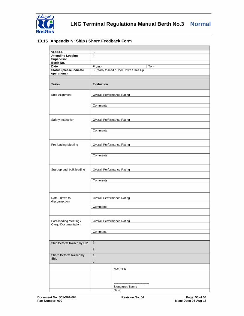
LNG Terminal Regulations Manual Berth No.3 Normal
Document No: S01-X01-004 Revision No: 04 Page: 50 of 54 Part Number: 000 Issue Date: 08-Aug-16
Appendix N: Ship / Shore Feedback Form 13.15
VESSEL :- Attending Loading Supervisor
:-
Berth No. Date From:- To :- Status:(please indicate operations)
:- Ready to load / Cool Down / Gas Up
Tasks
Evaluation
Ship Alignment
Overall Performance Rating Comments
Safety Inspection
Overall Performance Rating Comments
Pre-loading Meeting
Overall Performance Rating Comments
Start up until bulk loading
Overall Performance Rating Comments
Rate –down to disconnection
Overall Performance Rating
Comments
Post-loading Meeting / Cargo Documentation
Overall Performance Rating Comments
Ship Defects Raised by LM 1. 2.
Shore Defects Raised by Ship
1. 2.
MASTER
----------------------------------- Signature / Name
Date:

LNG Terminal Regulations Manual Berth No.3 Normal
Document No: S01-X01-004 Revision No: 04 Page: 51 of 54 Part Number: 000 Issue Date: 08-Aug-16
Guidelines:-
Overall Performance Rating
1 – Excellent 2 – Good 3 – Satisfactory 4 – Below Average 5 - Poor Operations shall be assessed on the followings :-
Communication skills during meetings , operations with Ship & Shore including Port Control , Agent , Shipping Ops. Etc.
knowledge of the processes (know exactly what they are doing)
Customer Relation Skills
The completed form duly signed is to be submitted to fleet Compatibility [email protected] via email upon departure of the vessel.
Appendix N: Jetty Boil Off Gas Recovery 13.16

LNG Terminal Regulations Manual Berth No.3 Normal
Document No: S01-X01-004 Revision No: 04 Page: 52 of 54 Part Number: 000 Issue Date: 08-Aug-16
LNG Berth-3
Step Action Action by Initials/
Date
JBOG recovery project intend to recover all BOG gasses flaring at berth generating from ship during long cool down operations and Loading Operations. Not intended to recover during ship tanks Gassing up operations or short period of cool down. However JBOG samples to be analyzed before lining up to recovery after gassing up operations. (manual sample connection provided across 71PV-3908)
JBOG manifold will be maintained under following status during berth holding mode
JBOG manifold line up as below:
Berth-3 trip to flare 71UZ-3916 (ESD-2 LEVEL) in active
71XV-3915 full open—30" Bypass JBOG manifold
71PV-3908 100% open on Manual-- JBOG manifold
71ESDV-3902 - full close – 30" JBOG recovery header
71HV-3905 – full close 30" JBOG recovery header
56QV-370801 and 56QV-370803 -- full open – 30” JBOG manifold
56QV-370802 – full close - 30” Bypass JBOG manifold
71ZSO-3909 – Buckling pin in place & close
56QV-370897 and 56QV-370804 – fully close – 2” BOG Recovery manual de-pressurizing line
Refer P&ID: 305/56/37/PR/DR/PI-322
PO SO RO
This following step should be taken in action at JBOG manifold for preparation of EDS-1 Test, confirmation and resetting at Berth- 3
Confirm JBOG manifold lined up as below before ESD-1 test carried out: Reset berth-3 trip to flare 71UZ-3916 (ESD-2
LEVEL)
Reset and Close 71XV-3915 – 30" Bypass JBOG manifold
71PV-3908 90% open on Manual-- JBOG manifold
Reset and Open 71ESDV-3902 – 30" JBOG recovery header
Keep Fully close 71HV-3905 – 30" JBOG recovery header
56QV-370897 and 56QV-370804 – fully close – 2” BOG Recovery manual de-pressurizing line
Refer P&ID: 305/56/37/PR/DR/PI-322
PO SO RO
When ESD-1 activated, confirm following actions : 71XV-3915 full Open— 30" Bypass JBOG
manifold
71PV-3908 100% open on Manual-- JBOG manifold
71ESDV-3902 - full close – 30" JBOG recovery header
Refer P&ID: 305/56/37/PR/DR/PI-322
PO SO RO

LNG Terminal Regulations Manual Berth No.3 Normal
Document No: S01-X01-004 Revision No: 04 Page: 53 of 54 Part Number: 000 Issue Date: 08-Aug-16
LNG Berth-3
Step Action Action by Initials/
Date
After confirming all required valves activated, reset following valves: Reset berth-3 trip to flare 71UZ-916 (ESD-2 LEVEL) 71XV-3915 full Close – 30" Bypass JBOG
manifold before JBOG recovery line up
71ESDV-3902 - full Open – 30" JBOG recovery header
Keep 71PV-3908 in Manual and full open-- JBOG manifold, until line up JBOG recovery system.
Refer P&ID: 305/56/37/PR/DR/PI-322
PO SO RO
This following step is preparation to lined up JBOG Manifold during cool down or loading from Berth-3
Confirm room availability at JBOG compressors (capacity Max 163t/hr) and ventures drawing capability from JBOG operator.
Confirm ship readiness and HD compressors running status during ship tanks cool down/ loading
Sample Jetty boil off gas (from manual sample across 71PV-3908) confirm BOG is on spec (N2 below 10 mol % This is applicable to the delivery end for BOG to ventures. ) )
SS
PO
RO
Confirm JBOG manifold line up as below:
56QV-370801 and 56QV-370803 full open – 30” JBOG manifold
56QV-370802 – Full close - 30” Bypass JBOG manifold
71ZSO-3909 – Buckling pin in place & close
56QV-370897 and 56QV-370804 – fully close – 2” ” BOG Recovery manual de-pressurizing line
Refer P&ID: 305/56/37/PR/DR/PI-322
PO SO RO
Line up JBOG recovery:
Reset 71UZ-3916 / Keep full open 71PV-3908 on manual
Reset and close 71XV-3915
Reset and open 71ESDV-3902
Open 71HV-3905 from DCS
Divert BOG to CCA by progressively closing pressure control valve 71PV-3908 on Manual until max.400 m barg (Max ship railing pressure 600 m barg) or until valve gets full close (communicate and reduce back pressure by opening 71PV-3908 if Ship compressors reaching to surge limit)
Keep 71PV-3908 on Auto with set pressure of 400 m barg
Confirm flow diverted to JBOG recovery by 71FI-3904A.
Confirm 71PV-3908 fully close on Auto, Record FQI readings
Refer P&ID: 305/56/37/PR/DR/PI-322
PO
RO

LNG Terminal Regulations Manual Berth No.3 Normal
Document No: S01-X01-004 Revision No: 04 Page: 54 of 54 Part Number: 000 Issue Date: 08-Aug-16
LNG Berth-3
Step Action Action by Initials/
Date
During normal operations – JBOG recovery mode
Monitor the following parameters:
71PV-3908 on Auto and controlling the pressure with given set point or below ( 400 m barg) and valve fully close during full recovery
Confirm no flaring at Jetty Flare (71FL-052) while full recovery.
Monitor recovery flows by 71FI-3903A & 71FI-3904A
Monitor Manifold pressures 71PT-3906/07/11
Monitor Manifold temperature 71TI-3912/13/14
56QV-370897 and 56QV-370804 – fully close – 2” ” BOG Recovery manual de-pressurizing line
Note: 1) Hi Hi pressure on Manifold trip set : 600mbarg (1oo2)
2) Lo Lo temperature on Manifold trip set : -135 deg C (2oo3)
3) Reverse flow 71FI-3903B & 71FI-3904B set at -0.5m/sec
Refer P&ID: 305/56/37/PR/DR/PI-322
RO
PO
This following step should be taken for JBOG recovery off line after loading completed
After completion of loading isolate JBOG recovery from the Berth-3 or whenever situation raises unable to recover JBOG
Inform JBOG operator and stop JBOG recovery before closing vapors from ship or recovery rate less than 10 tons/hr
Open gradually 71PV-3908 on manual, finally full open and leave the controller on manual.
when recovery flow comes below 10 tons/hr close 71HV-3905 fully
Activate 71UZ-3916 (trip to flare) and confirm
71XV-3915 full open and 71PV-3908 full open on manual.
71ESDV-3902 fully closed.
Note: Leave the system at these conditions until next ship JBOG recovery lining up.
SS
PO
RO


![FREEPORT LNG TERMINAL...FREEPORT LNG TERMINAL FREEPORT MARINE OPERATIONS MANUAL [10/24/18] 5 5.4 BERTH EQUIPMENT 33 5.4.1 Approach Speed Indicator Board 33 5.4.2 Mooring Line Tension](https://static.fdocuments.us/doc/165x107/606c9daef601e838141b241f/freeport-lng-terminal-freeport-lng-terminal-freeport-marine-operations-manual.jpg)