LNCS 3103 - Generating Multiaxis Tool Paths for Die and ... · PDF fileGenerating Multiaxis...
12
K. Deb et al. (Eds.): GECCO 2004, LNCS 3103, pp. 1287–1298, 2004. © Springer-Verlag Berlin Heidelberg 2004 Generating Multiaxis Tool Paths for Die and Mold Making with Evolutionary Algorithms Klaus Weinert and Marc Stautner Department for Machining Technology Baroper Str. 301, 44227 Dortmund, Germany {Weinert, Stautner}@isf.de http://www.isf.de Abstract. Defining tool paths for multiaxis milling is a difficult task that re- quires knowledge about the process and the behavior of the machine tool. Be- cause of the high risks of multiaxis movements within a real machine, the re- sulting paths are safe but normally sub-optimal. This article introduces a new method to obtain tool paths, which are free of collisions and optimal in consid- eration, the machine and its kinematics. The proposed method combines evolu- tionary algorithms and a newly developed efficient multiaxis milling simula- tion. The evolutionary algorithm uses multiple criteria for the optimization of a tool path. These criteria are minimized axial movement of the machine, mini- mal cutting forces and the exclusion of collisions between the workpiece and the non-cutting parts of the cutting tool. The approach uses multi-objective al- gorithms because minimal or no movement of a machine axis can lead to high cutting forces or multiple collisions. Along with the evolutionary algorithm, this article introduces a simulation for multiple axis milling. This simulation is able to compute the fitness of the given tool paths by considering the engage- ment condition and collision situation of a cutting tool. 1 Problem Description In multiaxis milling of free formed surfaces for die and mould making, one of the main tasks is a near optimal definition of the tool path. This definition is placed under various constraints, which need to be fulfilled simultaneously. One point is the avoid- ance of collisions between the non-cutting parts of the cutting tool and the work piece. A second one that is exclusive to multiaxis milling is the task of finding a tool orientation that fulfills all constraints resulting from the used machine. Different milling machines have different constraints imposed upon the movement of their ad- ditional axis, which are needed for the more than three axis movement. This can be seen as an additional collision condition between tool and possible movement area of the machine in addition to the collision between tool and free form surface. The third constraint is not exclusively given in multi axis milling; it is also valid for all milling processes. In milling processes, the cutting force on the cutting edge is
Transcript of LNCS 3103 - Generating Multiaxis Tool Paths for Die and ... · PDF fileGenerating Multiaxis...

K. Deb et al. (Eds.): GECCO 2004, LNCS 3103, pp. 1287–1298, 2004.© Springer-Verlag Berlin Heidelberg 2004
Generating Multiaxis Tool Paths for Die and MoldMaking with Evolutionary Algorithms
Klaus Weinert and Marc Stautner
Department for Machining Technology Baroper Str. 301,44227 Dortmund, Germany
{Weinert, Stautner}@isf.dehttp://www.isf.de
Abstract. Defining tool paths for multiaxis milling is a difficult task that re-quires knowledge about the process and the behavior of the machine tool. Be-cause of the high risks of multiaxis movements within a real machine, the re-sulting paths are safe but normally sub-optimal. This article introduces a newmethod to obtain tool paths, which are free of collisions and optimal in consid-eration, the machine and its kinematics. The proposed method combines evolu-tionary algorithms and a newly developed efficient multiaxis milling simula-tion. The evolutionary algorithm uses multiple criteria for the optimization of atool path. These criteria are minimized axial movement of the machine, mini-mal cutting forces and the exclusion of collisions between the workpiece andthe non-cutting parts of the cutting tool. The approach uses multi-objective al-gorithms because minimal or no movement of a machine axis can lead to highcutting forces or multiple collisions. Along with the evolutionary algorithm,this article introduces a simulation for multiple axis milling. This simulation isable to compute the fitness of the given tool paths by considering the engage-ment condition and collision situation of a cutting tool.
1 Problem Description
In multiaxis milling of free formed surfaces for die and mould making, one of themain tasks is a near optimal definition of the tool path. This definition is placed undervarious constraints, which need to be fulfilled simultaneously. One point is the avoid-ance of collisions between the non-cutting parts of the cutting tool and the workpiece. A second one that is exclusive to multiaxis milling is the task of finding a toolorientation that fulfills all constraints resulting from the used machine. Differentmilling machines have different constraints imposed upon the movement of their ad-ditional axis, which are needed for the more than three axis movement. This can beseen as an additional collision condition between tool and possible movement area ofthe machine in addition to the collision between tool and free form surface.
The third constraint is not exclusively given in multi axis milling; it is also validfor all milling processes. In milling processes, the cutting force on the cutting edge is
Verwendete Distiller 5.0.x Joboptions
Dieser Report wurde automatisch mit Hilfe der Adobe Acrobat Distiller Erweiterung "Distiller Secrets v1.0.5" der IMPRESSED GmbH erstellt. Sie koennen diese Startup-Datei für die Distiller Versionen 4.0.5 und 5.0.x kostenlos unter http://www.impressed.de herunterladen. ALLGEMEIN ---------------------------------------- Dateioptionen: Kompatibilität: PDF 1.2 Für schnelle Web-Anzeige optimieren: Nein Piktogramme einbetten: Nein Seiten automatisch drehen: Nein Seiten von: 1 Seiten bis: Alle Seiten Bund: Links Auflösung: [ 2400 2400 ] dpi Papierformat: [ 595 842 ] Punkt KOMPRIMIERUNG ---------------------------------------- Farbbilder: Downsampling: Ja Berechnungsmethode: Durchschnittliche Neuberechnung Downsample-Auflösung: 300 dpi Downsampling für Bilder über: 450 dpi Komprimieren: Ja Automatische Bestimmung der Komprimierungsart: Ja JPEG-Qualität: << /QFactor 0.5 /Blend 1 /HSamples [ 2 1 1 2 ] /VSamples [ 2 1 1 2 ] >> Bitanzahl pro Pixel: Wie Original Bit Graustufenbilder: Downsampling: Ja Berechnungsmethode: Durchschnittliche Neuberechnung Downsample-Auflösung: 300 dpi Downsampling für Bilder über: 450 dpi Komprimieren: Ja Automatische Bestimmung der Komprimierungsart: Ja JPEG-Qualität: << /QFactor 0.5 /Blend 1 /HSamples [ 2 1 1 2 ] /VSamples [ 2 1 1 2 ] >> Bitanzahl pro Pixel: Wie Original Bit Schwarzweiß-Bilder: Downsampling: Ja Berechnungsmethode: Durchschnittliche Neuberechnung Downsample-Auflösung: 1800 dpi Downsampling für Bilder über: 2700 dpi Komprimieren: Ja Komprimierungsart: CCITT CCITT-Gruppe: 4 Graustufen glätten: Nein Text und Vektorgrafiken komprimieren: Nein SCHRIFTEN ---------------------------------------- Alle Schriften einbetten: Ja Untergruppen aller eingebetteten Schriften: Nein Wenn Einbetten fehlschlägt: Warnen und weiter Einbetten: Immer einbetten: [ /Courier-BoldOblique /Helvetica-BoldOblique /Courier /Helvetica-Bold /Times-Bold /Courier-Bold /Helvetica /Times-BoldItalic /Times-Roman /ZapfDingbats /Times-Italic /Helvetica-Oblique /Courier-Oblique /Symbol ] Nie einbetten: [ ] FARBE(N) ---------------------------------------- Farbmanagement: Farbumrechnungsmethode: Farbe nicht ändern Methode: Standard Geräteabhängige Daten: Einstellungen für Überdrucken beibehalten: Ja Unterfarbreduktion und Schwarzaufbau beibehalten: Ja Transferfunktionen: Anwenden Rastereinstellungen beibehalten: Ja ERWEITERT ---------------------------------------- Optionen: Prolog/Epilog verwenden: Ja PostScript-Datei darf Einstellungen überschreiben: Ja Level 2 copypage-Semantik beibehalten: Ja Portable Job Ticket in PDF-Datei speichern: Nein Illustrator-Überdruckmodus: Ja Farbverläufe zu weichen Nuancen konvertieren: Ja ASCII-Format: Nein Document Structuring Conventions (DSC): DSC-Kommentare verarbeiten: Ja DSC-Warnungen protokollieren: Nein Für EPS-Dateien Seitengröße ändern und Grafiken zentrieren: Ja EPS-Info von DSC beibehalten: Ja OPI-Kommentare beibehalten: Nein Dokumentinfo von DSC beibehalten: Ja ANDERE ---------------------------------------- Distiller-Kern Version: 5000 ZIP-Komprimierung verwenden: Ja Optimierungen deaktivieren: Nein Bildspeicher: 524288 Byte Farbbilder glätten: Nein Graustufenbilder glätten: Nein Bilder (< 257 Farben) in indizierten Farbraum konvertieren: Ja sRGB ICC-Profil: sRGB IEC61966-2.1 ENDE DES REPORTS ---------------------------------------- IMPRESSED GmbH Bahrenfelder Chaussee 49 22761 Hamburg, Germany Tel. +49 40 897189-0 Fax +49 40 897189-71 Email: [email protected] Web: www.impressed.de
Adobe Acrobat Distiller 5.0.x Joboption Datei
<< /ColorSettingsFile () /AntiAliasMonoImages false /CannotEmbedFontPolicy /Warning /ParseDSCComments true /DoThumbnails false /CompressPages false /CalRGBProfile (sRGB IEC61966-2.1) /MaxSubsetPct 100 /EncodeColorImages true /GrayImageFilter /DCTEncode /Optimize false /ParseDSCCommentsForDocInfo true /EmitDSCWarnings false /CalGrayProfile () /NeverEmbed [ ] /GrayImageDownsampleThreshold 1.5 /UsePrologue true /GrayImageDict << /QFactor 0.9 /Blend 1 /HSamples [ 2 1 1 2 ] /VSamples [ 2 1 1 2 ] >> /AutoFilterColorImages true /sRGBProfile (sRGB IEC61966-2.1) /ColorImageDepth -1 /PreserveOverprintSettings true /AutoRotatePages /None /UCRandBGInfo /Preserve /EmbedAllFonts true /CompatibilityLevel 1.2 /StartPage 1 /AntiAliasColorImages false /CreateJobTicket false /ConvertImagesToIndexed true /ColorImageDownsampleType /Average /ColorImageDownsampleThreshold 1.5 /MonoImageDownsampleType /Average /DetectBlends true /GrayImageDownsampleType /Average /PreserveEPSInfo true /GrayACSImageDict << /QFactor 0.5 /Blend 1 /HSamples [ 2 1 1 2 ] /VSamples [ 2 1 1 2 ] >> /ColorACSImageDict << /QFactor 0.5 /Blend 1 /HSamples [ 2 1 1 2 ] /VSamples [ 2 1 1 2 ] >> /PreserveCopyPage true /EncodeMonoImages true /ColorConversionStrategy /LeaveColorUnchanged /PreserveOPIComments false /AntiAliasGrayImages false /GrayImageDepth -1 /ColorImageResolution 300 /EndPage -1 /AutoPositionEPSFiles true /MonoImageDepth -1 /TransferFunctionInfo /Apply /EncodeGrayImages true /DownsampleGrayImages true /DownsampleMonoImages true /DownsampleColorImages true /MonoImageDownsampleThreshold 1.5 /MonoImageDict << /K -1 >> /Binding /Left /CalCMYKProfile (U.S. Web Coated (SWOP) v2) /MonoImageResolution 1800 /AutoFilterGrayImages true /AlwaysEmbed [ /Courier-BoldOblique /Helvetica-BoldOblique /Courier /Helvetica-Bold /Times-Bold /Courier-Bold /Helvetica /Times-BoldItalic /Times-Roman /ZapfDingbats /Times-Italic /Helvetica-Oblique /Courier-Oblique /Symbol ] /ImageMemory 524288 /SubsetFonts false /DefaultRenderingIntent /Default /OPM 1 /MonoImageFilter /CCITTFaxEncode /GrayImageResolution 300 /ColorImageFilter /DCTEncode /PreserveHalftoneInfo true /ColorImageDict << /QFactor 0.9 /Blend 1 /HSamples [ 2 1 1 2 ] /VSamples [ 2 1 1 2 ] >> /ASCII85EncodePages false /LockDistillerParams false >> setdistillerparams << /PageSize [ 595.276 841.890 ] /HWResolution [ 2400 2400 ] >> setpagedevice

1288 K. Weinert and M. Stautner
an important factor for a stable and safe process control. The programming of toolpaths must lead to a process that is fast and safe to be cost efficient.
Resulting from these constraints multiaxis tool path strategies are often designed asan addition to the existing three axis strategies. These paths are planned as a three-axis movement with an additional two-axis movement, which changes the orientationof the tool to the work piece. This additional rotational movement has to be free ofcollisions. Therefore, plenty of user experience is needed to design these tool paths.There are some software tools on the market that deliver some kind of collision de-tection but they are often restricted to three axis milling or only to collision detectionagainst the final geometry and not the actual process geometry of the free form sur-face. So there is a demand for solutions which provide functions to develop tool pathswhich are free of collisions and use the possibilities of multi axis tool path program-ming to gain a fast and safe process course. This article introduces a first prototype ofa tool that enables the user to convert given three axis tool paths to collision freemultiaxis tool paths.
2 General Idea
The main concept consists of two steps. In the first step, a user starts designing a con-version solution for a given three-axis tool path and a given workpiece. In a secondstep, a software tool optimizes the user’s parameters considering all constraints andoptimizing facilities. After this second step, the resulting tool path leads to an effi-cient multi axis milling process, which is free of collisions and fulfills all machine re-strictions.
The general idea for converting three axis milling paths into multiaxis paths, is tokeep the position of the tool tip and to add a varying the orientation to the tool. Theresulting surface remains the same when only ball end mills are used. Only the qualityof the surface will improve resulting from the more advantageous engagement condi-tions. Several studies have shown that this simple tool tilt strategy leads to useful andefficient multi axis paths with minimal amount of manual user input.
2.1 Manual Step
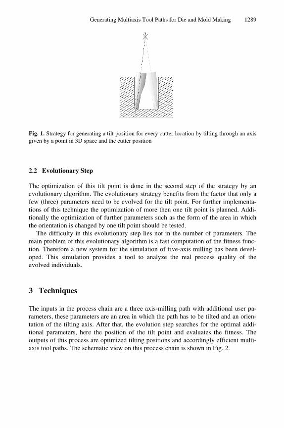
The user determines a tilt point in 3D space. The multiaxis path is then generated bytilting the tool so that the main axis of the tool, shank and holder lead through an axisdetermined by the tilt point and the point on the tool path. This strategy is illustratedin Fig. 1. This tilt point strategy has several benefits: it is easy to develop and the re-sulting tool paths lead to smooth movements of the machine axis, because thesemovements can often be executed by tilting in one machine axis and then by rotatingthe second machine axis. One disadvantage is the indirect change of the tool paths bychanging a point in 3D space. It is easy to find or see a useful position for this point,but it is difficult to determine that this point is the optimal one that leads to a minimalmovement of the tool axis and is free of collisions.
Generating Multiaxis Tool Paths for Die and Mold Making 1289
Fig. 1. Strategy for generating a tilt position for every cutter location by tilting through an axisgiven by a point in 3D space and the cutter position
2.2 Evolutionary Step
The optimization of this tilt point is done in the second step of the strategy by anevolutionary algorithm. The evolutionary strategy benefits from the factor that only afew (three) parameters need to be evolved for the tilt point. For further implementa-tions of this technique the optimization of more then one tilt point is planned. Addi-tionally the optimization of further parameters such as the form of the area in whichthe orientation is changed by one tilt point should be tested.
The difficulty in this evolutionary step lies not in the number of parameters. Themain problem of this evolutionary algorithm is a fast computation of the fitness func-tion. Therefore a new system for the simulation of five-axis milling has been devel-oped. This simulation provides a tool to analyze the real process quality of theevolved individuals.
3 Techniques
The inputs in the process chain are a three axis-milling path with additional user pa-rameters, these parameters are an area in which the path has to be tilted and an orien-tation of the tilting axis. After that, the evolution step searches for the optimal addi-tional parameters, here the position of the tilt point and evaluates the fitness. Theoutputs of this process are optimized tilting positions and accordingly efficient multi-axis tool paths. The schematic view on this process chain is shown in Fig. 2.

1290 K. Weinert and M. Stautner
Fig. 2. Proposed two step process chain
3.1 Discrete Milling Simulation
Several products on the market allow a simulation of milling processes. Most of them[1] are not capable of simulating multiaxis milling processes. There are simulationsthat can perform this task but these techniques contain disadvantages, which preventutilization for the fitness determination.
There is the group of exact simulation approaches. Kawashima [2] describes an ac-curate technique called “Grafttree” to speed up a solid modeling approach. The work-piece and the arbitrarily shaped tool are modeled by a CSG-tree. Constructive SolidGeometry (CSG) is an object-construction method used in several 3D-CAD systems.Objects are basically constructed by combining simple solid objects with Boolean op-erators, such as union or intersection as described by Foley et al. [3]. Sourin andPasko [4] developed another approach; they simulate the cutting tool analytically withthe use of procedurally defined time-dependent defining functions. Both approaches,the “Grafttree” and the one made by Sourin and Pasko are exact but time consuming.
A second group of techniques is the approximate approaches. One technique is thepolygonal approach described by Glaeser [5]. Here a polygonal representation of theworkpiece, called “Γ-buffer”, was processed with a polygonal representation of theswept volume of the tool, which was determined by differential geometry. This ap-proach can lead to large mesh sizes that are reduced for display by a recursive subdi-vision scheme.
Another group of approximate techniques is the “dexel” approach. Hook [6] con-verts the workpiece into a discrete “dexel structure” which is derived from the z-buffer approach in computer graphics [3]. One problem of Hook’s approach is that,similar to the z-buffer algorithm, the dexel structure has to be aligned with a viewingvector. Therefore, after changing the viewing position, the whole simulation processhas to be redone. A determination of fitness values through the simulation is not pos-sible.
Extensions to this approach were made by Huang [7] and Weinert [8]. These ex-tensions are independent of the viewer’s position and process the input NC-file bymodeling the cutting operation at each discrete position on a given path. To achieve
Generating Multiaxis Tool Paths for Die and Mold Making 1291
high accuracy with low memory usage, these discrete simulations do not have theability to simulate undercuts, thus they are only able to simulate a three-axis millingprocess.
For the usage in these evolutionary algorithms a new simulation of milling proc-esses based on these dexel techniques has been developed. This new simulation al-lows free scalable level of simulation resolution to reduce simulation time and pro-vides a fast collision testing and extra interface functions to derive a fitness ofsimulated tool path. The simulation is able to detect and benchmark the amount ofcollisions and to take account of the restrictions resulting from the different mechani-cal capabilities of the used machine.
3.2 The Evolutionary Algorithm
As shown by Castelino et al. [9] evolutionary algorithms, which are used in processplanning for nc-machining are primarily, specialized in the optimization of generaltool movement. These solutions refer to algorithms developed for the traveling sales-man problem or the lawnmower problem. Due to their large non-linear search spaces,both problems are often used for evolutionary algorithm. An overview on this subjectis presented by Alander [10]. The algorithms in this area of problems do not focus onthe machine abilities and the engagement conditions.
In our algorithm, the problem that needs to be solved is a simple three dimensionalsearch. Therefore we can use a rather simple (µ, λ) evolutionary strategy ES. Thisleads to good results without optimized evolutionary parameters. This is a conse-quence of the simple three dimensional evolution problems, which have to be solved.A tournament selection operator defines two groups of individuals that compete witheach other. Every survivor of a tournament replaces the inferior individual. A survi-vor of a tournament is the individual that has a higher fitness value compared to itscompetitor.
As is shown in the results section, simple problems can be solved in less than 20generations with values for µ of 50 and a λ of 25. This behavior is important the use-fulness of the introduced system. The determination of the fitness of a single individ-ual can be very time consuming. Milling processes have real running times of up to20 hours. State of the art milling simulations can be 10 times faster than the real proc-ess. So defining a fitness of a single individual phenotype can be very time consum-ing.
3.2.1 Fitness DeterminationThe fitness function uses three different types of fitnesses that were determined sepa-rately and result from different constraints and collisions.1. Collision with the space bound by not reachable axis values of the used machine.2. Collisions of the workpiece with the non-cutting parts of the tool such as shank or
holder. All collisions in a simulation run are added up to a single value. Thisvalue shows how much volume of the material collides with the tool. Therefore,

1292 K. Weinert and M. Stautner
slight touching collisions result in different values as full collisions. This is ameasurement for the amount of collisions with the machine.
3. The third value is the amount of harmony in the resulting movement of the ma-chine. The simulation returns a value that represents how easy the machine mayfollow the suggested movement. This value has a direct influence on the real pro-cess milling times and the resulting surface quality.
These three values represent multiple criteria for the fitness determination. A com-bination is used for the selection of the individuals.
3.2.2 Selection MethodThe algorithm uses a truncation or (µ, λ) selection [11]. The selection schema for theλ best individuals is in pseudo code.
for (c=0;c<[NumberOfFitnessValues];c++){ if (I1.f[c] > I2.f[c]) return true; if (I1.f[c] < I2.f[c]) return false;};
Where I1 and I2 are the current individuals with their respective arrays of fitnessvalues. In our algorithm, there are three different fitness values. The ranking dependson the order of the fitness values in the array. In our algorithm the order is
1. machine constraints,2. amount of collisions and3. movement harmony.
Therefore, at first a tool path needs to be free of both types of collisions and afterthat the algorithm searches for the position that leads to the most harmonic movementof the machine axis.
3.2.3 Recombination and CrossoverThe Recombination is done via a two individual crossover. Two individuals are ran-domly chosen from λ selected ones (see Sect. 3.2.2) ignoring their fitnesses. Thecrossover randomly chooses values from both individuals. This crossover reduces thefitness pressure so that searches in the solution space are more efficiently.
4 First Results
First tests were carried out on specially designed workpieces, which allow a fast andsimple design of the evolutionary algorithm. The use of these test cases allows veri-fying the design of the EA and helps to reduce unwanted time losses from errors inthe implementation of the algorithms. The test workpieces are designed with theCAD/CAM software CATIA to ensure the functionality of the complete processchain.

Generating Multiaxis Tool Paths for Die and Mold Making 1293
4.1 Test Workpieces
The tests should verify the algorithm on both opposed possibilities that occur in realworkpieces. Therefore, the first workpiece is a deep cavity. This is a typical form indie and mould making. Cavities are difficult to mill if they are of a certain depth and asmall diameter, because this necessitates tools with long thin tool shanks. The use oflong shanks causes undesirable effects on the surface quality and increases the highrisk of tool breakage. To overcome these effects the process speeds need to be re-duced. The second workpiece is a dome that has a steep rising edge in the middle ofthe workpieces Fig. 3. (right). This workpiece needs to be milled with long shank aswell to enable the processing of the small diameter (1 mm) fillet at the base of thedome.
Although both test workpieces have their ideal tool tilt point in the center of theworkpieces they have different constraints. The collision spaces are completely dif-ferent so that the collision avoidance leads to different demands on the evolution pro-gression. The simulation can only deliver a value of how many collisions have oc-curred. As a consequence the fitness landscapes are different, and a parameterizationwhich is suitable for both cases should be suitable for real workpieces as well.
Fig. 3. Test workpieces and their tooling paths. Negative Cavity (left), Positive Dome (right)
4.1.1 Tool-Shank-HolderThe employed, simulated tool is a ball end mill with a diameter of 2 mm and an edgelength of 1 mm. This part of the tool cannot lead to collisions. To ensure an increasedsurface quality after the evolution a shorter, thicker tool shank was use for the evolu-tion. This tool cannot be used on the original three axis paths. The colliding part ofthe tool is the shank, which has a cone as basic form and the holder. In our test work-piece, only collisions between workpiece and shank are to be expected because of thelength of the shank.

1294 K. Weinert and M. Stautner
4.1.2. The Cavity WorkpieceThe initial tool paths for the cavity are some short finishing paths on the ground ofthe cavity (see Fig. 3). At this point of the milling process, the chance of a collision ismost likely. The milling of these paths is not possible with a three-axis strategy andthe chosen shank-holder combination.
The initial search space for the positioning of the tool points is from -40 mm to+40 mm along all axes of the global object space. There are 50 initial individuals thatare spread stochastically over this 80x80x80 mm search space. To obtain an overviewof the behavior of the algorithm this test run is repeated 20 times.
Fig. 4. Average fitnesses from 20 evolution runs with 50 individuals in each population. (Cav-ity Workpiece)
The diagrammed fitness in Fig. 4. is the accumulated, normalized fitness of bothcollision constraints. As can be seen, the maximal fitness reaches 1 in approx. 10 gen-erations. This shows that collision free tilt points can be reached and there is enoughtime for a more difficult search for the optimal tool point.
4.1.3 The Dome WorkpieceThe tool path on the second workpiece is different to the path introduced before. Thecollision here is most likely at the inner paths where edge of the dome is approached,see Fig. 5. Because of the similar dimensions of the workpiece all parameters remainthe same. This allows obtaining an overview of the behavior of the algorithm on dif-ferent parts without the use of extra knowledge.

Generating Multiaxis Tool Paths for Die and Mold Making 1295
Fig. 5. Average fitnesses from 20 evolution runs with 50 individuals each generation. (DomeWorkpiece)
As it can be seen in Fig. 5. the general behavior of the algorithm is similar a colli-sion free position is found in approx 10 generations. After that the fitness is deter-mined by the harmony fitness value.
4.2 Real Workpiece
The pre- parameterized algorithm is now used for a real workpiece. The chosenworkpiece and the three axis milling paths are not specially designed for five-axismilling or for this evolutionary path design. The workpiece originates from the Euro-pean High Speed Machining Award 2000. To preclude a three axis processing a shankbased on a cone is used. Surface quality is expected to be better if the process is car-ried out with the shorter and sturdier conical shank, the present three-axis tool pathswill lead to a collision if they are used with this tool, though.
As a test-processing step, a finishing step was chosen. This finishing step consistsof approx. 65000 single lines of nc-code. As in the test runs, 50 individuals perpopulation are used. The initial search space for these tests is200mm x 200mm x 200mm according to the larger dimensions of the workpiece(160mm x 160mm x 40mm). The tool paths can be seen in Fig. 6.

1296 K. Weinert and M. Stautner
Fig. 6. Workpiece, from the European High Speed Machining Award 2000
Fig. 7. Average fitnesses from 10 evolution runs with 50 individuals each generation
Fig. 7. shows a fitness plot for 10 subsequent test runs. Each run consist of approx.50 generations with 50 individuals in each generation. In this plot only the collision(workpiece tool and tool machine space) fitnesses are combined. The path of the firstcurve which is the average maximal fitness of an individual shows that a collisionfree position is found by the algorithm on average within the first 10 generations ofthe evolution. Until generation 20 the other values for average fitness and for minimal

Generating Multiaxis Tool Paths for Die and Mold Making 1297
fitness increase accordingly. After generation 20 the average minimal fitness de-creases. The reason for this behavior lies in the machine constraints: the collision freetilt point is close to the edge of the region reachable by the machine. The algorithmdraws all individuals close to this border and therefore a minimal movement of thetool point leads to tool paths that cannot be realized by the machine kinematics. Thefitness of these tool points is set to zero. Therefore, the more points reach the optimalpoint that is close to this edge the more points can accidentally jump over. This is thereason for the slightly decreasing average fitness.
5 Conclusions and Outlook
This paper presents a new system for the optimization of tool paths and engagementconditions for multiaxis milling as well as the generation of efficient multiaxis toolpaths. First studies show that the proposed multi criteria evolutionary algorithm issuitable to deliver an efficient evolution in combination with an efficient simulationsystem. The simple parameterization of the algorithm allows the application of thesystem on different problem cases without further user knowledge about the evolu-tionary parameters. Although the introduced software system is an academic proto-type, this qualifies enables this technique as basis for a commercial solution for mul-tiaxis path generation in CAM applications.
Further implementations are planned based on other generation strategies and re-quire a more complex genome. More advanced multiaxis strategies may be developedwith this system without the use of three axis tool paths as basis for the evolution.
Acknowledgements. The authors like to thank the Deutsche Forschungsgemeinschaftfor financial support as part of the Collaborative Research Center “ComputationalIntelligence” (SFB 531).
References
1. Müller, H.; Surmann, T; Stautner, M; Albersmann, F.; Weinert, K.: Online Sculpting andVisualization of Multi-Dexel Volumes. In: SM’03, Eighth ACM Symposium on SolidModeling and Applications, Elber, G.; Shapiro, V. (eds.), Seattle, Washington, USA,ACM 1-58113-706-0/03/0006, ACM Press, NY, USA, June 16-20, S. 258-261
2. Kawashima, Y; Itoh, K.; Ishida, T.; Nonaka, S; Ejiri, K.: A flexible quantitative methodfor NC machining verification using a space-division based solid model. The Visual Com-puter 7 (1991), pp. 149-157
3. Foley, J. D.; Dam, A. van; Feiner, S. K.; Hughes, J.F.: Computer Graphics: Principles andPractice. Addison-Wesley, New-York 1992
4. Sourin, A.I.; Pasko A.A.: Function Representation for Sweeping by a Moving Solid. IEEETransactions on Visualization and Computer Graphics 2 (1996) 2, pp. 11-18

1298 K. Weinert and M. Stautner
5. Glaeser, G.; Gröller, E.: Efficient Volume-Generation During the Simulation of NC-Milling. Technical Report TR-186-2-97-10, April 1997, Institute of Computer Graphicsand Algorithms, Vienna University of Technology
6. Hook, T. van: Real Time shaded NC Milling Display. Computer Graphics 20 (1986) 4,pp. 15-20
7. Huang, Y.; Oliver, J.H.: NC Milling error Assessment and Tool Path Correction. In: Com-puter Graphics Proceedings, Conference Proceedings July 19-24 (1994), pp. 287-294
8. Weinert, K.; Müller, H.; Friedhoff, J.: Efficient discrete simulation of 3-axis milling forsculptured surfaces. Production Engineering 3 (1998) 2, pp. 83-88.
9. Castelino, K.; D’Souza, R.;Wright, P. K.: Tool-path Optimization for Minimizing Airtimeduring Machinig, Mechanical Engineering Dept. University of California at Berkeley,http://kingkong.me.berkeley.edu/~kenneth/research/pubs/airtime_minimization_joms.pdf
10. Alander, J., T.: An Indexed Bibliography of Genetic Algorithms and the Traveling Sales-man Problem. Internal Report 94-1-TSP, University of Vaasa, Department of InformationTechnology and Production Economics, Finland
11. Banzhaf, W; Nordin, P; Keller, R. E.; Francone, F. D.: Genetic Programming : An Intro-duction : On the Automatic Evolution of Computer Programs and Its Applications.Morgan Kaufmann Publishers, Inc. San Francisco, Cal.