LM27403 Synchronous Buck Converter 1 of 12 Power Management Solutions LM27403 Synchronous Buck...
13
Created on: 5/18/2015 Revised on: 5/19/2015 PMP10691 Test Results Page 1 of 12 Power Management Solutions LM27403 Synchronous Buck Converter TI reference design number: PMP10691 Input: 12V Output: 3.3V @ 35A DC – DC Test Results
Transcript of LM27403 Synchronous Buck Converter 1 of 12 Power Management Solutions LM27403 Synchronous Buck...
Created on: 5/18/2015
Revised on: 5/19/2015
PMP10691 Test Results
Page 1 of 12 Power Management Solutions
LM27403 Synchronous Buck Converter
TI reference design number: PMP10691
Input: 12V
Output: 3.3V @ 35A
DC – DC Test Results
Created on: 5/18/2015
Revised on: 5/19/2015
PMP10691 Test Results
Page 2 of 12 Power Management Solutions
Table of Contents
1 Circuit Description ...................................................................................................... 3 2 Photos ....................................................................................................................... 3 3 Efficiency ................................................................................................................... 5 4 Thermal Tests ............................................................................................................ 7
4.1 Test Setup .......................................................................................................... 7 4.2 30A Load, No Airflow .......................................................................................... 8
5 Startup and Shutdown Behavior ................................................................................ 9 5.1 Turn-on and Turn-off from Vin ............................................................................ 9 5.2 Turn-on and Turn-off from EN .......................................................................... 10
6 Switching and Ripple ............................................................................................... 11 6.1 Switching and Ripple ........................................................................................ 11
7 Load Transient Response ........................................................................................ 12
7.1 Load Transient Response................................................................................. 12
Created on: 5/18/2015
Revised on: 5/19/2015
PMP10691 Test Results
Page 3 of 12 Power Management Solutions
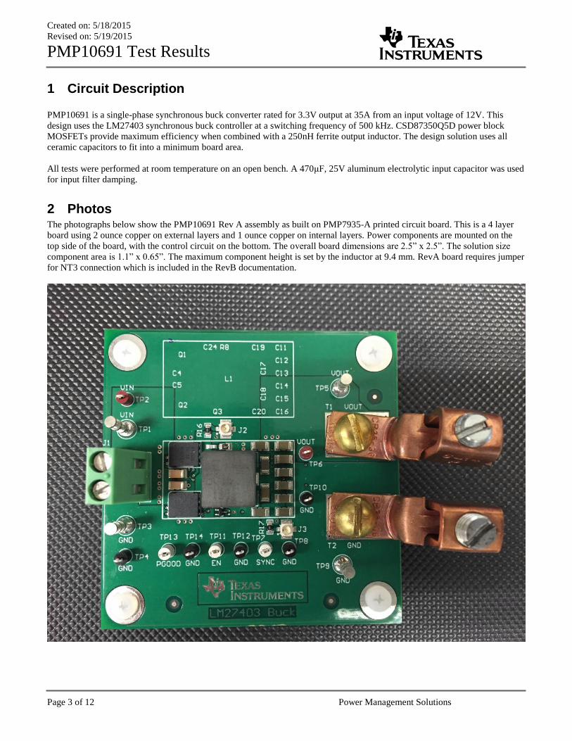
1 Circuit Description
PMP10691 is a single-phase synchronous buck converter rated for 3.3V output at 35A from an input voltage of 12V. This
design uses the LM27403 synchronous buck controller at a switching frequency of 500 kHz. CSD87350Q5D power block
MOSFETs provide maximum efficiency when combined with a 250nH ferrite output inductor. The design solution uses all
ceramic capacitors to fit into a minimum board area.
All tests were performed at room temperature on an open bench. A 470μF, 25V aluminum electrolytic input capacitor was used
for input filter damping.
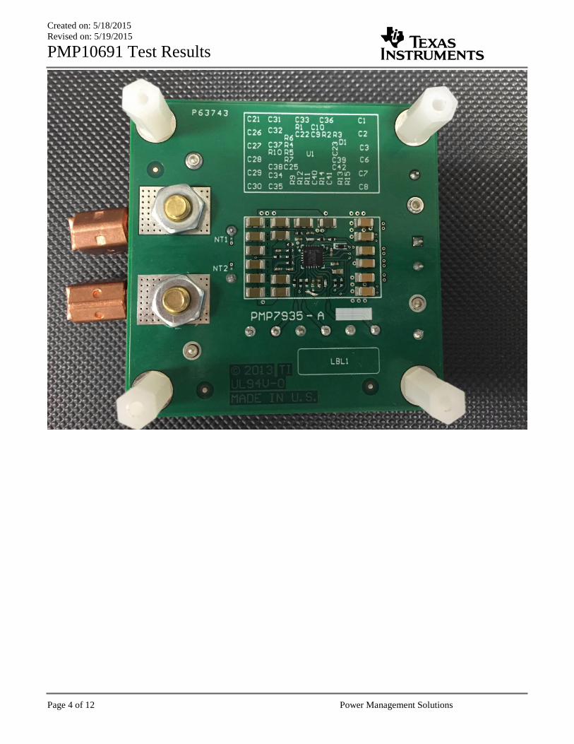
2 Photos The photographs below show the PMP10691 Rev A assembly as built on PMP7935-A printed circuit board. This is a 4 layer
board using 2 ounce copper on external layers and 1 ounce copper on internal layers. Power components are mounted on the
top side of the board, with the control circuit on the bottom. The overall board dimensions are 2.5” x 2.5”. The solution size
component area is 1.1” x 0.65”. The maximum component height is set by the inductor at 9.4 mm. RevA board requires jumper
for NT3 connection which is included in the RevB documentation.
Created on: 5/18/2015
Revised on: 5/19/2015
PMP10691 Test Results
Page 4 of 12 Power Management Solutions
Created on: 5/18/2015
Revised on: 5/19/2015
PMP10691 Test Results
Page 5 of 12 Power Management Solutions
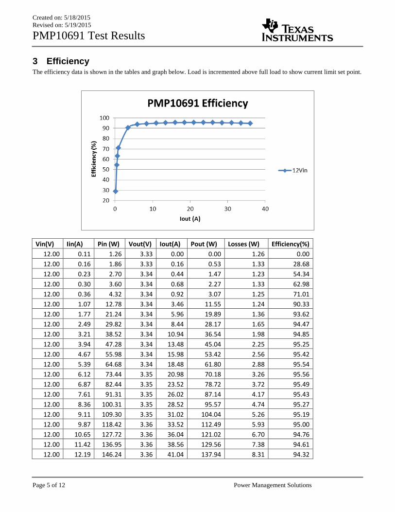
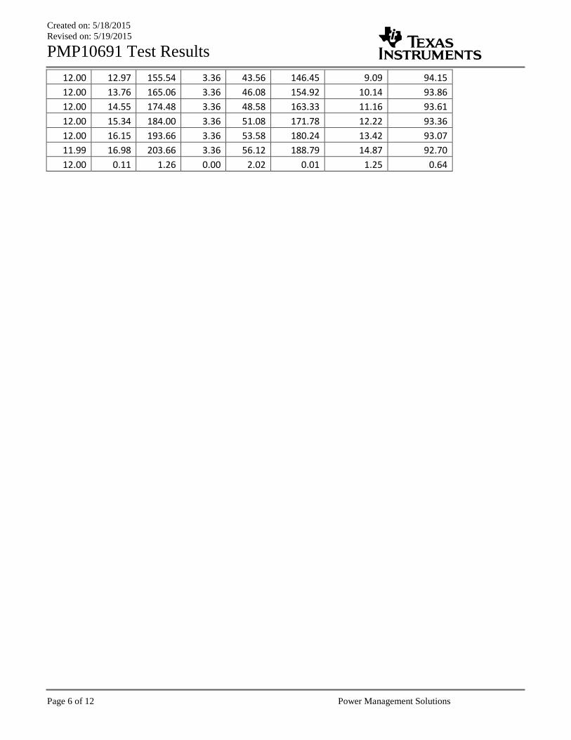
3 Efficiency The efficiency data is shown in the tables and graph below. Load is incremented above full load to show current limit set point.
Vin(V) Iin(A) Pin (W) Vout(V) Iout(A) Pout (W) Losses (W) Efficiency(%)
12.00 0.11 1.26 3.33 0.00 0.00 1.26 0.00
12.00 0.16 1.86 3.33 0.16 0.53 1.33 28.68
12.00 0.23 2.70 3.34 0.44 1.47 1.23 54.34
12.00 0.30 3.60 3.34 0.68 2.27 1.33 62.98
12.00 0.36 4.32 3.34 0.92 3.07 1.25 71.01
12.00 1.07 12.78 3.34 3.46 11.55 1.24 90.33
12.00 1.77 21.24 3.34 5.96 19.89 1.36 93.62
12.00 2.49 29.82 3.34 8.44 28.17 1.65 94.47
12.00 3.21 38.52 3.34 10.94 36.54 1.98 94.85
12.00 3.94 47.28 3.34 13.48 45.04 2.25 95.25
12.00 4.67 55.98 3.34 15.98 53.42 2.56 95.42
12.00 5.39 64.68 3.34 18.48 61.80 2.88 95.54
12.00 6.12 73.44 3.35 20.98 70.18 3.26 95.56
12.00 6.87 82.44 3.35 23.52 78.72 3.72 95.49
12.00 7.61 91.31 3.35 26.02 87.14 4.17 95.43
12.00 8.36 100.31 3.35 28.52 95.57 4.74 95.27
12.00 9.11 109.30 3.35 31.02 104.04 5.26 95.19
12.00 9.87 118.42 3.36 33.52 112.49 5.93 95.00
12.00 10.65 127.72 3.36 36.04 121.02 6.70 94.76
12.00 11.42 136.95 3.36 38.56 129.56 7.38 94.61
12.00 12.19 146.24 3.36 41.04 137.94 8.31 94.32
Created on: 5/18/2015
Revised on: 5/19/2015
PMP10691 Test Results
Page 6 of 12 Power Management Solutions
12.00 12.97 155.54 3.36 43.56 146.45 9.09 94.15
12.00 13.76 165.06 3.36 46.08 154.92 10.14 93.86
12.00 14.55 174.48 3.36 48.58 163.33 11.16 93.61
12.00 15.34 184.00 3.36 51.08 171.78 12.22 93.36
12.00 16.15 193.66 3.36 53.58 180.24 13.42 93.07
11.99 16.98 203.66 3.36 56.12 188.79 14.87 92.70
12.00 0.11 1.26 0.00 2.02 0.01 1.25 0.64
Created on: 5/18/2015
Revised on: 5/19/2015
PMP10691 Test Results
Page 7 of 12 Power Management Solutions
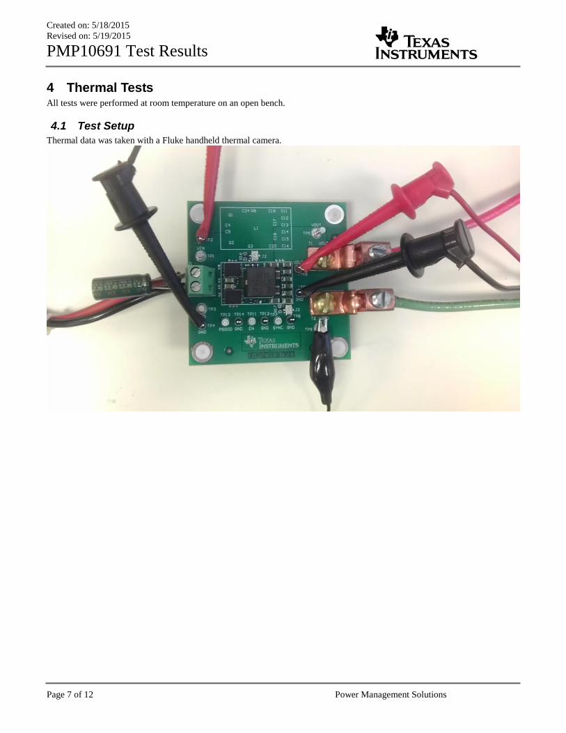
4 Thermal Tests All tests were performed at room temperature on an open bench.
4.1 Test Setup
Thermal data was taken with a Fluke handheld thermal camera.
Created on: 5/18/2015
Revised on: 5/19/2015
PMP10691 Test Results
Page 8 of 12 Power Management Solutions
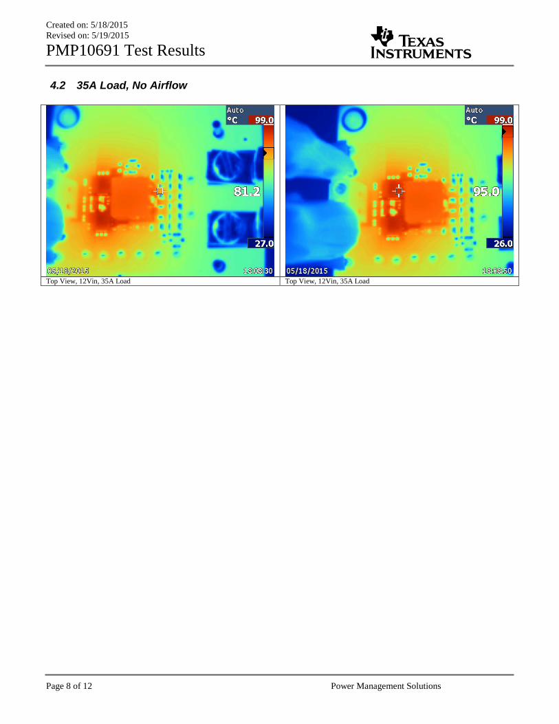
4.2 35A Load, No Airflow
Top View, 12Vin, 35A Load Top View, 12Vin, 35A Load
Created on: 5/18/2015
Revised on: 5/19/2015
PMP10691 Test Results
Page 9 of 12 Power Management Solutions
5 Startup and Shutdown Behavior
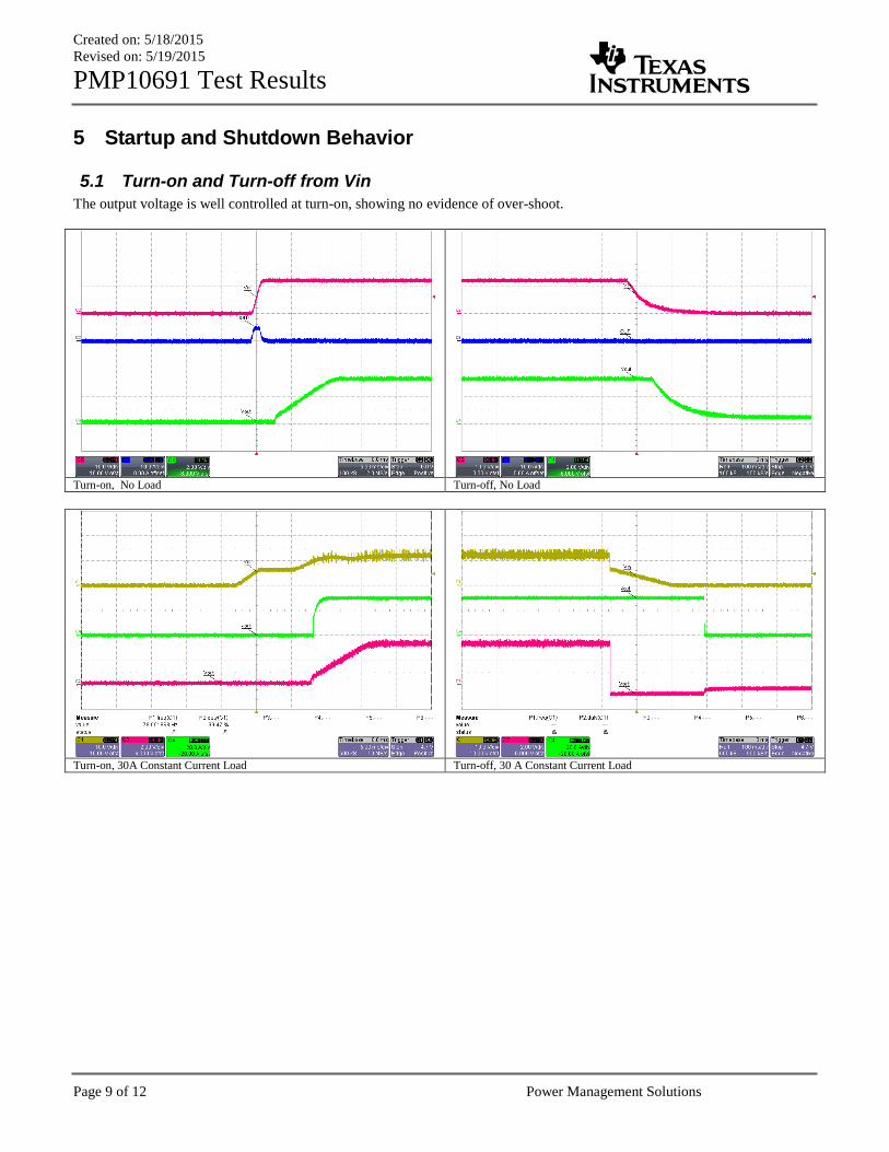
5.1 Turn-on and Turn-off from Vin
The output voltage is well controlled at turn-on, showing no evidence of over-shoot.
Turn-on, No Load Turn-off, No Load
Turn-on, 30A Constant Current Load Turn-off, 30 A Constant Current Load
Created on: 5/18/2015
Revised on: 5/19/2015
PMP10691 Test Results
Page 10 of 12 Power Management Solutions
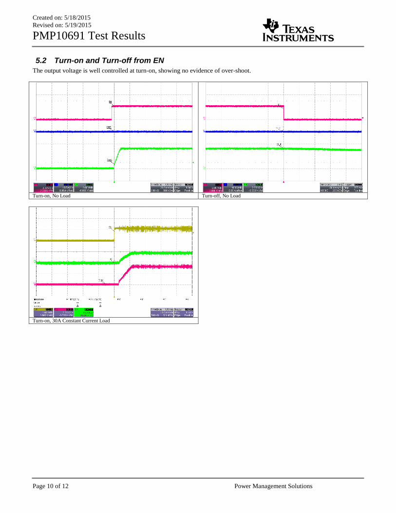
5.2 Turn-on and Turn-off from EN
The output voltage is well controlled at turn-on, showing no evidence of over-shoot.
Turn-on, No Load Turn-off, No Load
Turn-on, 30A Constant Current Load
Created on: 5/18/2015
Revised on: 5/19/2015
PMP10691 Test Results
Page 11 of 12 Power Management Solutions
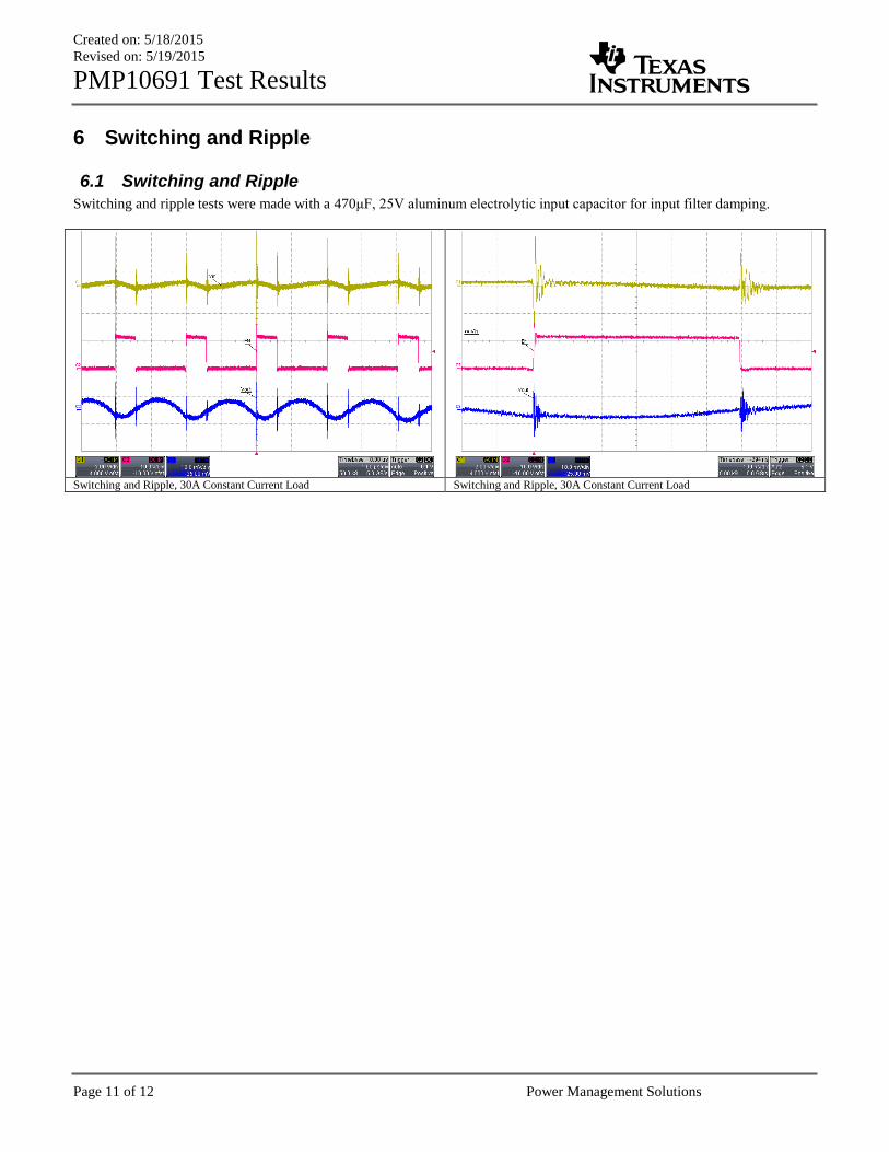
6 Switching and Ripple
6.1 Switching and Ripple
Switching and ripple tests were made with a 470μF, 25V aluminum electrolytic input capacitor for input filter damping.
Switching and Ripple, 30A Constant Current Load Switching and Ripple, 30A Constant Current Load
Created on: 5/18/2015
Revised on: 5/19/2015
PMP10691 Test Results
Page 12 of 12 Power Management Solutions
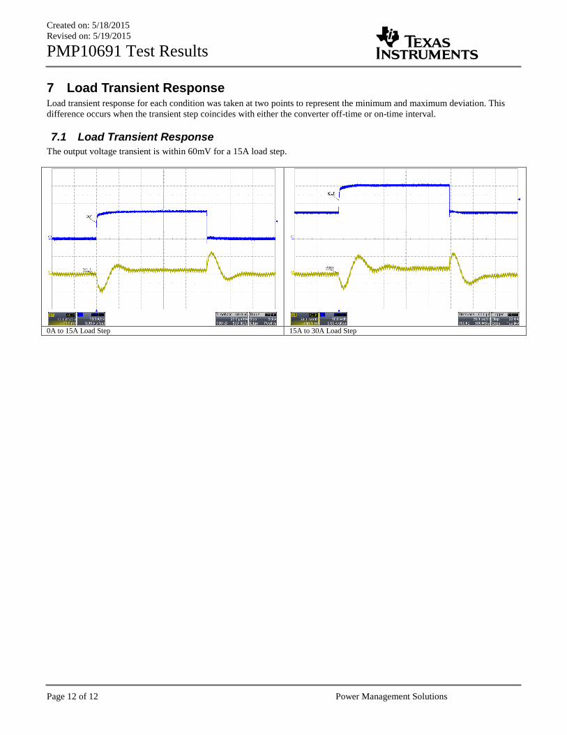
7 Load Transient Response Load transient response for each condition was taken at two points to represent the minimum and maximum deviation. This
difference occurs when the transient step coincides with either the converter off-time or on-time interval.
7.1 Load Transient Response
The output voltage transient is within 60mV for a 15A load step.
0A to 15A Load Step 15A to 30A Load Step
IMPORTANT NOTICE FOR TI REFERENCE DESIGNS
Texas Instruments Incorporated ("TI") reference designs are solely intended to assist designers (“Buyers”) who are developing systems thatincorporate TI semiconductor products (also referred to herein as “components”). Buyer understands and agrees that Buyer remainsresponsible for using its independent analysis, evaluation and judgment in designing Buyer’s systems and products.TI reference designs have been created using standard laboratory conditions and engineering practices. TI has not conducted anytesting other than that specifically described in the published documentation for a particular reference design. TI may makecorrections, enhancements, improvements and other changes to its reference designs.Buyers are authorized to use TI reference designs with the TI component(s) identified in each particular reference design and to modify thereference design in the development of their end products. HOWEVER, NO OTHER LICENSE, EXPRESS OR IMPLIED, BY ESTOPPELOR OTHERWISE TO ANY OTHER TI INTELLECTUAL PROPERTY RIGHT, AND NO LICENSE TO ANY THIRD PARTY TECHNOLOGYOR INTELLECTUAL PROPERTY RIGHT, IS GRANTED HEREIN, including but not limited to any patent right, copyright, mask work right,or other intellectual property right relating to any combination, machine, or process in which TI components or services are used.Information published by TI regarding third-party products or services does not constitute a license to use such products or services, or awarranty or endorsement thereof. Use of such information may require a license from a third party under the patents or other intellectualproperty of the third party, or a license from TI under the patents or other intellectual property of TI.TI REFERENCE DESIGNS ARE PROVIDED "AS IS". TI MAKES NO WARRANTIES OR REPRESENTATIONS WITH REGARD TO THEREFERENCE DESIGNS OR USE OF THE REFERENCE DESIGNS, EXPRESS, IMPLIED OR STATUTORY, INCLUDING ACCURACY ORCOMPLETENESS. TI DISCLAIMS ANY WARRANTY OF TITLE AND ANY IMPLIED WARRANTIES OF MERCHANTABILITY, FITNESSFOR A PARTICULAR PURPOSE, QUIET ENJOYMENT, QUIET POSSESSION, AND NON-INFRINGEMENT OF ANY THIRD PARTYINTELLECTUAL PROPERTY RIGHTS WITH REGARD TO TI REFERENCE DESIGNS OR USE THEREOF. TI SHALL NOT BE LIABLEFOR AND SHALL NOT DEFEND OR INDEMNIFY BUYERS AGAINST ANY THIRD PARTY INFRINGEMENT CLAIM THAT RELATES TOOR IS BASED ON A COMBINATION OF COMPONENTS PROVIDED IN A TI REFERENCE DESIGN. IN NO EVENT SHALL TI BELIABLE FOR ANY ACTUAL, SPECIAL, INCIDENTAL, CONSEQUENTIAL OR INDIRECT DAMAGES, HOWEVER CAUSED, ON ANYTHEORY OF LIABILITY AND WHETHER OR NOT TI HAS BEEN ADVISED OF THE POSSIBILITY OF SUCH DAMAGES, ARISING INANY WAY OUT OF TI REFERENCE DESIGNS OR BUYER’S USE OF TI REFERENCE DESIGNS.TI reserves the right to make corrections, enhancements, improvements and other changes to its semiconductor products and services perJESD46, latest issue, and to discontinue any product or service per JESD48, latest issue. Buyers should obtain the latest relevantinformation before placing orders and should verify that such information is current and complete. All semiconductor products are soldsubject to TI’s terms and conditions of sale supplied at the time of order acknowledgment.TI warrants performance of its components to the specifications applicable at the time of sale, in accordance with the warranty in TI’s termsand conditions of sale of semiconductor products. Testing and other quality control techniques for TI components are used to the extent TIdeems necessary to support this warranty. Except where mandated by applicable law, testing of all parameters of each component is notnecessarily performed.TI assumes no liability for applications assistance or the design of Buyers’ products. Buyers are responsible for their products andapplications using TI components. To minimize the risks associated with Buyers’ products and applications, Buyers should provideadequate design and operating safeguards.Reproduction of significant portions of TI information in TI data books, data sheets or reference designs is permissible only if reproduction iswithout alteration and is accompanied by all associated warranties, conditions, limitations, and notices. TI is not responsible or liable forsuch altered documentation. Information of third parties may be subject to additional restrictions.Buyer acknowledges and agrees that it is solely responsible for compliance with all legal, regulatory and safety-related requirementsconcerning its products, and any use of TI components in its applications, notwithstanding any applications-related information or supportthat may be provided by TI. Buyer represents and agrees that it has all the necessary expertise to create and implement safeguards thatanticipate dangerous failures, monitor failures and their consequences, lessen the likelihood of dangerous failures and take appropriateremedial actions. Buyer will fully indemnify TI and its representatives against any damages arising out of the use of any TI components inBuyer’s safety-critical applications.In some cases, TI components may be promoted specifically to facilitate safety-related applications. With such components, TI’s goal is tohelp enable customers to design and create their own end-product solutions that meet applicable functional safety standards andrequirements. Nonetheless, such components are subject to these terms.No TI components are authorized for use in FDA Class III (or similar life-critical medical equipment) unless authorized officers of the partieshave executed an agreement specifically governing such use.Only those TI components that TI has specifically designated as military grade or “enhanced plastic” are designed and intended for use inmilitary/aerospace applications or environments. Buyer acknowledges and agrees that any military or aerospace use of TI components thathave not been so designated is solely at Buyer's risk, and Buyer is solely responsible for compliance with all legal and regulatoryrequirements in connection with such use.TI has specifically designated certain components as meeting ISO/TS16949 requirements, mainly for automotive use. In any case of use ofnon-designated products, TI will not be responsible for any failure to meet ISO/TS16949.IMPORTANT NOTICE
Mailing Address: Texas Instruments, Post Office Box 655303, Dallas, Texas 75265Copyright © 2015, Texas Instruments Incorporated