
Live Tracer_MO9
8
OPERATION AND SAFETY INSTRUCTION MANUAL Part Number: 16-14-600-GL General Information The Live Tracer is used to trace the path of live non-metallic gas mains. The kit utilizes a traceable fiberglass rodder and a stuffing box to enable tracing while main- taining no blow by. Use with custom insertion tap tee for entry into gas mains. Use any transmitter and receiver to trace gas main from above ground. Jacket Core Wire 1/4” OD Rod DISCLAIMER The foregoing instructions are provided by Jameson LLC to give guidance regarding the use of its gas line tracer products. Jameson LLC cannot be responsible for any use of its products that does not comply with these instructions. However, you are also cautioned to comply with all instructions, regulations and requirements provide by the owner of the property and of the gas line, whether a utility company, governmental body or otherwise. You must also conform to and comply with all of your employer’s requirements. To the extent of any questions or any conflicts between instructions from Jameson and from anyone else, please consult your supervisor as to the proper course of action. 800.346.1956 WWW.JAMESONLLC.COM Electrofusion Insertion Tapping Tee (Sold Separately) Patent Pending Since 1956 Read and understand these operating and safety instructions before using or servicing this equipment. Failure to follow instructions could result in an accident causing serious in- jury. Do not allow children or untrained personnel to use this equipment. Follow your company installation procedures.
-
Upload
cathey-hayes -
Category
Documents
-
view
13 -
download
2
Transcript of Live Tracer_MO9

OPERATION AND SAFETY INSTRUCTION MANUAL
Part Number: 16-14-600-GL
General Information
The Live Tracer is used to trace the path of live non-metallic gas mains.
The kit utilizes a traceable fiberglass rodder and a stuffing box to enable tracing while main-taining no blow by.
Use with custom insertion tap tee for entry into gas mains. Use any transmitter and receiver to trace gas main from above ground.
Jacket Core Wire
1/4” OD Rod
DISCLAIMERThe foregoing instructions are provided by Jameson LLC to give guidance regarding the use of its gas line tracer products. Jameson LLC cannot be responsible for any use of its products that does not comply with these instructions. However, you are also cautioned to comply with all instructions, regulations and requirements provide by the owner of the property and of the gas line, whether a utility company, governmental body or otherwise. You must also conform to and comply with all of your employer’s requirements. To the extent of any questions or any conflicts between instructions from Jameson and from anyone else, please consult your supervisor as to the proper course of action.
800.346.1956WWW.JAMESONLLC.COM
Electrofusion Insertion Tapping Tee (Sold Separately)
Patent Pending
Since 1956
Read and understand these operating and safety instructions before using or servicing this equipment. Failure to follow instructions could result in an accident causing serious in-jury. Do not allow children or untrained personnel to use this equipment.Follow your company installation procedures.

Traceable Fiberglass Rodder - Unit has 1/4” diameter rod with permanent 5/16” diameter end ferrule, Rod has copper trace wire embedded in fiberglass core and is coated with polypropylene jacket for safety and durability.
Accessory Kit - Canvas Storage Bag, Grounding Cable, 3 Screws, 11 O-Rings, Rod Lubricant, Hex Key Driver, Adhesive, Replacement End Ferrule, Spring Leader, Grounding Clip
Stuffing Box - Designed with custom o-ring to provide seal when rod is inserted into pressurized lines for use up to 100 psi. Includes 4” pipe nipple with 1” NPT thread.
NOTICEThe components of the Live Tracer system are specifically designed to work exclusively with each other.
The use of these components individually or in combination with other non-Jameson tools or accessories is not recommended and will not guarantee the safety or effectiveness of the system.
Required tools not included in this kit:Gas leak detector / soap solution
Transmitter and Receiver for locating
Wrenches, channel locks
Various pipe fittings (may be required to adapt 1” NPT to your specific fitting)
Teflon tape / pipe dope
Grease gun with 1/4” button fitting
Specific parts and accessories may vary according to your
company procedures.
Part Number16-14-600-GL
Sold Separately
Electrofusion Insertion Tapping Tee
Live Tracer Kit
Live Tracer Accessories - Sold Separately16-2-TEE Electrofusion Tapping Tee for 2” Gas Main (4.7 mm resistor terminals)
15-WIPE Lubricating Wipes - Feeding Rod into Stuffing Box
16-AWIPE Large Alcohol Wipes, 60 ct. - Clean Pipe for Electrofusion
16-169 Spring Leader
16-168 Flexible Sonde Adapter - Attaches Sonde to Rod
16-170 O-Ring Replacements, 10 ct.
16-SB Stuffing Box, Three Screws, Six O-Rings
16-HVTAP HV Tap Tool
16-CW HVTT Cap Wrench
16-EFC-1 1” IPS Electrofusion Coupling (4.7 mm resistor terminals)
16-1HSCR Hand Scraper - Prepare Pipe for Electrofusion
16-RSCR 2” IPS Rotary Scraper - Prepare Pipe for Electrofusion
16-1PSCR 1” Poly Peeler - Prepare 1” Pipe (PUP)
16-TC HVTT Test Cap
16-TCG HVTT Test Cap with Gauge
16-HVTTR HVTT Tool Ratchet Handle
16-PROC Processor
16-PUP-12 PUP Extension Valve Assembly (12” Lead)
16-FLEX Flex Riser Valve Assembly
16-146 End Ferrule Replacement Kit
16-B7105 1” X 24” IPS, PE4710 Bronze Male Thread Transition
16-B7110 1” X 24” CTS, PE4710 Bronze Male Thread Transition
16-45ELB 45º Elbow, 1” IPS
Read and understand these operating and safety instructions before using or servicing this equipment. Failure to follow instructions could result in an accident causing serious injury. Do not allow children or untrained personnel to use this equipment.Follow your company installation procedures.
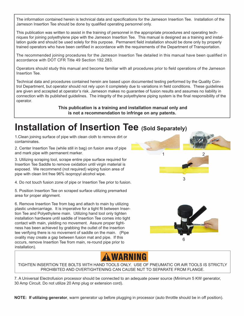
1.Clean joining surface of pipe with clean cloth to remove dirt or contaminates. 2. Center Insertion Tee (while still in bag) on fusion area of pipe and mark pipe with permanent marker.3. Utilizing scraping tool, scrape entire pipe surface required for Insertion Tee Saddle to remove oxidation until virgin material is exposed. We recommend (not required) wiping fusion area of pipe with clean lint free 96% isopropyl alcohol wipe.
4. Do not touch fusion zone of pipe or Insertion Tee prior to fusion.
5. Position Insertion Tee on scraped surface utilizing premarked area for proper alignment.
6. Remove Insertion Tee from bag and attach to main by utilizing plastic undercarriage. It is imperative for a tight fit between Inser-tion Tee and Polyethylene main. Utilizing hand tool only tighten installation hardware until saddle of Insertion Tee comes into tight contact with main, yielding no movement. Assure proper tight-ness has been achieved by grabbing the outlet of the insertion tee verifying there is no movement of saddle on the main. (Pipe ovality may create a gap between fusion mat and pipe. If this occurs, remove Insertion Tee from main, re-round pipe prior to installation).
1 2
3
TIGHTEN INSERTION TEE BOLTS WITH HAND TOOLS ONLY. USE OF PNEUMATIC OR AIR TOOLS IS STRICTLY PROHIBITED AND OVERTIGHTENING CAN CAUSE NUT TO SEPARATE FROM FLANGE.
6
The information contained herein is technical data and specifications for the Jameson Insertion Tee. Installation of the Jameson Insertion Tee should be done by qualified operating personnel only.
This publication was written to assist in the training of personnel in the appropriate procedures and operating tech-niques for joining polyethylene pipe with the Jameson Insertion Tee. This manual is designed as a training and instal-lation guide and should be used solely for this purpose. Permanent field installation should be done only by properly trained operators who have been certified in accordance with the requirements of the Department of Transportation.
The recommended joining procedures for the Jameson Insertion Tee detailed in this manual have been qualified in accordance with DOT CFR Title 49 Section 192.283.
Operators should study this manual and become familiar with all procedures prior to field operations of the Jameson Insertion Tee.
Technical data and procedures contained herein are based upon documented testing performed by the Quality Con-trol Department, but operator should not rely upon it completely due to variations in field conditions. These guidelines are given and accepted at operator’s risk. Jameson makes no guarantee of fusion results and assumes no liability in connection with its published guidelines. The integrity of the polyethylene piping system is the final responsibility of the operator.
This publication is a training and installation manual only and is not a recommendation to infringe on any patents.
7. A Universal Electrofusion processor should be connected to an adequate power source (Minimum 5 KW generator, 30 Amp Circuit. Do not utilize 20 Amp plug or extension cord).
NOTE: If utilizing generator, warm generator up before plugging in processor (auto throttle should be in off position).
Installation of Insertion Tee (Sold Separately)

10. Utilizing center line mark on coupling (while still in bag) mark the stab depth.
11. Scrape fusion area to stab depth.
12. Repeat process marking stab depth on Transition Fitting or Pipe Pup.
13. Fuse coupling on transition or pipe pup.
14. Screw ball valve on to extension. Make sure valve is in “closed” position.
15. Remove Insertion Tee Cap and Install Test Cap to test saddle fusion and EF coupling fusion.
16. Remove Test Cap from Insertion Tee and attach tapping tool to cutter with threaded adapter on tapping tool shaft. It may be necessary to back out cutter first to enable attachment of threaded adapter.
Advance cutter with tapping tool until the stop is engaged completing hot tap. Back out cutter with tapping tool and seal against top of tapping tee body. This ensures cutter does not restrict flow of gas in tee outlet or rod insertion.
Installation of Insertion Tee (continued)
10 11
12 13
14 15
16
8. Make sure to check Insertion Tee fusion time and cooling time with reading on processor. If readings match, start fusion. If not, refer to instruction manual furnished by manufacturer of processor.
9. After fusion is complete, Clamping Device should remain in place during the recommended cooling time. Plastic undercarriage may remain on pipe after fusion or may be removed after recommended Total Cooling Time. Do not continue until Total Cooling Time has elapsed.
8-9
800.346.1956WWW.JAMESONLLC.COM

Rod
Stuffing Box Cap
O-ring
1/4” Grease Fitting
Stuffing Box Body
End Ferrule
Spring Leader
Accessory
Screws
Live Tracer OperationBefore Each Use:
Inspect O-ring for any sign of tearing, cracking or pitting. Replace if damaged BEFORE EVERY USE. Jameson O-rings are custom designed. Only Jameson-provided O-rings will guarantee proper safety and effectiveness.
Inspect rod for damage. If rod surface is broken, replace rod. A scratched rod could cause leaking when scratch passes through Stuffing Box O-ring. Portions of rod can be cut away and new end fitting attached if it is not necessary to replace entire rod.
Follow your company safety procedures at all times. These instructions shall not take the precedence over any safety procedures established by your company.
1. Access PE gas pipe to be traced. Install electrofusion Tap Tee to pipe. Follow all installation and safety procedures provided with your equipment and those established by your company.
Install Rod into Stuffing Box2. Remove cap of Stuffing Box by removing the 3 screws.
3. INSPECT O-RING. If it shows any sign of tearing, cracking or pitting, replace with new O-ring.
4. Pay out rod approximately 15 feet.
5. Remove spring accessory then install rod end through Stuffing Box cap as shown.
6. Lubricate end ferrule, rod and inside O-ring with lubricated wipes provided. Install O-ring over rod.
7. Insert rod end into Stuffing Box body.
8. Attach Spring Leader Accessory to end ferrule of rod.
9. Install Stuffing Box cap with 3 screws provided. Snugly secure all screws to ensure proper O-ring seal.
10. Attach Stuffing Box to angled access port of Tap Tee. Follow your company’s procedures for attaching to access port.
11. Open valve and check for gas leaks following your company procedures. If Stuffing Box is leaking, inspect O-rings and rod for damage. Replace as necessary.
12. Mark rod with permanent marking pen 6” from Stuffing Box to monitor retracting of rod.
800.346.1956WWW.JAMESONLLC.COM

Live Tracer Operation
Insert Rod for Tracing13. Push rod into Tap Tee while holding a lubricated wipe against rod to continuously lubricate rod. Lack of lubrication can result in excessive push force on rod and could cause breakage. Adjust drag brake on rodder to allow controlled payout rate of rod. Reel should only spin when rod is ac-tively being pushed into pipe. Reel must spin while paying out or risk tangling and damage to rod.14. FIBERGLASS ROD IS FRAGILE. When pushing rod, keep hands within 1 foot of stuffing box to avoid kinking rod. Do not attempt to force rod past obstructions. Do not repeatedly pull rod back and re-insert with a ramming motion. Do not allow rod to buckle at entry of Stuffing Box under ex-cessive force as this can result in rod breakage. If rod hits firm obstruction, stop pushing and trace at that point. 15. When insertion is nearly complete, allow 2-3 coils of rod to remain on spool to prevent slippage and potential rod damage.
Tracing the Rod 16. Attach transmitter cable red clip to end fitting at opposite end of rod attached to reel. Follow manufacturer’s instruc-tions for proper set-up of transmitter.17. It is recommended to install ground spike at a 90 degree angle to anticipated rod path. If you have a 1W trans-mitter, use highest frequency available. If your transmitter is greater than 1W, use highest frequency below 45kHz. Follow proper locating practices established by your company or your locating equipment manufacturer.
Removing the Rod18. When tracing is complete, pull rod back through Tap Tee and reinstall onto rod spool. Adjust drag brake to apply light tension on reel. Manually push rod into reel. DO NOT manually spin reel to take up rod. Reel should spin only while actively pushing rod into reel. The rod should always lie firmly along inner edges of reel. A second person may be required to manage this task.19. A grease fitting is available on Stuffing Box for lubrication when removing rod. Use a standard ¼” grease gun and company approved synthetic non-petroleum grease to lubricate rod. If this is not available, periodically reinsert the rod a few inches while using lubricating wipe and then continue removing.20. When black mark on rod end is visible, stop removing the rod. Do not pull rod end past the O-ring as this will dam-age the O-ring.21. Close valve.22. Remove the Stuffing Box. Disassemble Stuffing Box from rod end.23. Reinstall Stuffing Box cap for storage.24. Use squeeze tool to crimp 1” PE access pipe. Cap pipe per company procedures.
NOTE: Traceable rodder has a copper wire that can be inserted underground. Jameson cannot guarantee successful tracing for every make and model transmitter under all soil and moisture conditions. If tracing is unsuccessful, try increas-ing depth of ground spike or wetting area around ground spike.
800.346.1956WWW.JAMESONLLC.COM
NOTE: STATIC CHARGE GROUNDING If static charge grounding is required, attach grounding clips to ground spike (not included) and to bare metal at end of wheel axle.

ATTACHING NEW END FERRULE
1. Cut away damaged section(s) of rod with a fine-tooth hacksaw, cable cutter or sharp knife. With pipe cutter and/or sharp knife, strip red protective jacket back from fiberglass core approximately 5/8”. Do not cut fiberglass core when stripping jacket. Do not crush fiberglass core.
2. Copper wire is embedded in outer surface of fiberglass core. Use knife to pick loose end of copper wire from fiberglass core. Peel wire away from fiberglass core with needle nose pliers.
3. Use knife to carefully scrape away enamel coating on outer surface of wire. Re-seat wire into fiberglass core, allowing it to remain free from surface of fiberglass core. This will enable contact with inside of new end ferrule.
4. Attempt a test fit of replacement end ferrule over exposed fiberglass core. It should be firm and snug with little or no play to assure wire con-tacts inside of ferrule. If too loose, cut away rod end and repeat Steps 1-4.
5. Once proper fit is established, install end ferrule without adhesive and check for continuity of the internal copper wire using a digital multimeter. Touch a probe to end ferrule at each end of coiled rod. Any resistance reading (generally between 2-12 ohms) indicates proper continuity.
6. Remove end ferrule. Clean rod end and end ferrule with cleaning solvent or alcohol to remove debris and glass fibers. Allow solvent to completely evaporate. Step 6 is extremely important.
7. Mix and apply adhesive to entire surface of fiberglass core and wire. Insert rod into end ferrule as far as possible, enclosing end of red jacket in counterbore of ferrule. Wipe away excess adhesive.
8. Check rod again for continuity using digital multimeter. The adhesive remains workable for 20 minutes. If no continuity, remove ferrule, clean off adhesive and repeat steps 1-7.
Note: Repaired rod should be allowed to cure 24 hours prior to use.
800.346.1956WWW.JAMESONLLC.COM
End Ferrule Repair
Fig. 1
Fig. 2
Red Jacket
Fiberglass Core
Fold Wire Back Along Flat Portion
5/8”
Red Jacket
Fiberglass Core
Copper Wire
5/8”
5/8”
Read manufacturer’s instructions before using adhesive. In case of eye contact, flush with water and seek medical attention If skin contact occurs, apply solvent (such as nail polish remover) to area and gently remove adhesive. Wash solvent off with water. Solvents should not be used in case of contact with eyes or open wounds. Always wear safety goggles (ANSI Std. Z87.1) and gloves when working with adhesive and/or unprotected fiberglass rod.
Jacket Core Wire
1/4” OD Rod

LT_MO9
Example for fabricating permanent installation for re-location of gas
main through insertion tee.
Alternate configuration for vertical insertion of rod: Insertion Tee with 45º Elbow
(16-HVTTR required for tapping this configuration)
800.346.1956WWW.JAMESONLLC.COM
FUSION TIME COOLING TIMETOTAL
COOLING TIMEMinimum
KVA
Minimum Generator
BreakerSeconds Minutes Minutes
In clamp position * and
prior to movementPrior to pressure taps and backfilling
1” CTS Coupling * 45 10 20 1.0 10
1” IPS Coupling* 50 10 20 1.0 10
2” Insertion Tee 90 10 25 1.0 10
* Clamping required on couplings
WarrantyJameson products carry a warranty against any defect in material and workmanship for a period of one year from date of shipment unless failure is due to misuse or improper application. Jameson shall in no event be responsible or liable for modifications, alterations, misapplications or repairs made to its products by purchaser or others. This warranty is limited to repair or replacement of the product and does not include reimbursement for shipping or other expenses incurred. Jameson disclaims any other express or implied warranty.