Live Tank Circuit Breakers - library.e.abb.com · developing, testing and manufacturing high...
104
Live Tank Circuit Breakers — Buyer´s Guide 0-1 Edition 2, 2003-06 Live Tank Circuit Breakers Buyer´s Guide
Transcript of Live Tank Circuit Breakers - library.e.abb.com · developing, testing and manufacturing high...

Live Tank Circuit Breakers — Buyer´s Guide 0-1Edition 2, 2003-06
Live Tank Circuit BreakersBuyer´s Guide
Live Tank Circuit Breakers — Buyer´s GuideA-1 Edition 2, 2003-06 Live Tank Circuit Breakers — Buyer´s Guide A-2Edition 2, 2003-06
Contents
Introduction A-2
Explanations B-1
Puffer, Auto-PufferTM C-1
Design Features and Advantages:
LTB Circuit Breaker Family D-1
HPL Circuit Breaker Family E-1
BLK Operating Mechanism F-1
BLG Operating Mechanism G-1
MD Motor Drive Operating Mechanism H-1
Technical Catalogues:
LTB Circuit Breaker Family I-1
HPL Circuit Breaker Family J-1
BLK Operating Mechanism K-1
BLG Operating Mechanism L-1
MD Motor Drive Operating Mechanism M-1
Optional for Special Applications:
Composite Insulators N-1
Controlled Switching O-1
Monitoring P-1
Seismic Withstand Capability Q-1
Quality Control and Testing R-1
Enquiry Data S-1
Products
TechnicalInformation
Chapter-Page
Table of Contents

Live Tank Circuit Breakers — Buyer´s GuideA-1 Edition 2, 2003-06 Live Tank Circuit Breakers — Buyer´s Guide A-2Edition 2, 2003-06
Exceeding Customer Expectations — ABB Live Tank Circuit Breakers
Introduction
ABB has over a century of experience in developing, testing and manufacturing high voltage circuit breakers. Through the years, our circuit breakers have acquired a reputation for high reliability and long life in all climates and in all parts of the world.
ABB is currently introducing the
future technology for operating mechanisms. We can now present the Motor Drive, a digital servo motor system with electronics for control and monitoring.
Our development program is strongly focused on providing added value for our customers.
Product Range Type
MaximumRated
Voltage(kV)
Maximum Rated
Current(A)
MaximumRated
BreakingCurrent
(kA)
Circuit Breaker type LTBSF6 Auto-Puffer™ interrupter designSpring or Motor Drive operating mechanism(s)
LTB D1/B 170 3150 40
LTB E1 245 4000 50
LTB E2 550 4000 50
Circuit Breaker type HPLSF6 puffer interrupter designSpring operating mechanism(s)
HPL B1 300 4000 63
HPL B2 550 4000 63
HPL B4 800 4000 63
Controlled Switching Switchsync™
Condition Monitoring OLM2
Other data and/or special applications not covered in this Buyer’s Guide will be quoted on request.
For information on Configurable Switchgear Solutions with LTB and HPL SF6 Circuit Breakers – (i.e. Withdrawable Circuit Breakers, Disconnecting Circuit Breakers and Line Entrance Modules), please see separate brochures.
Live Tank Circuit Breakers — Buyer´s GuideB-1 Edition 2, 2003-06 Live Tank Circuit Breakers — Buyer´s Guide B-2Edition 2, 2003-06
Explanations
Explanations
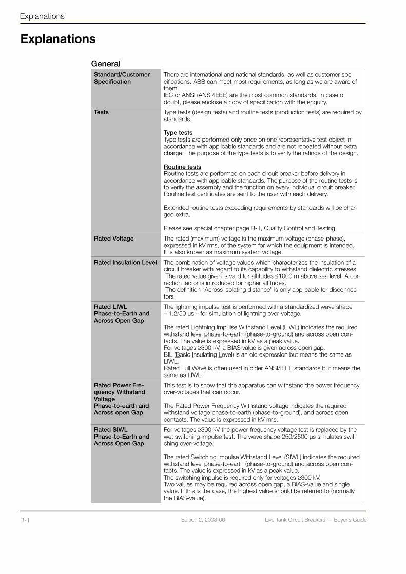
GeneralStandard/Customer Specification
There are international and national standards, as well as customer spe-cifications. ABB can meet most requirements, as long as we are aware of them. IEC or ANSI (ANSI/IEEE) are the most common standards. In case of doubt, please enclose a copy of specification with the enquiry.
Tests Type tests (design tests) and routine tests (production tests) are required by standards.
Type testsType tests are performed only once on one representative test object in accordance with applicable standards and are not repeated without extra charge. The purpose of the type tests is to verify the ratings of the design.
Routine testsRoutine tests are performed on each circuit breaker before delivery in accordance with applicable standards. The purpose of the routine tests is to verify the assembly and the function on every individual circuit breaker. Routine test certificates are sent to the user with each delivery.
Extended routine tests exceeding requirements by standards will be char-ged extra.
Please see special chapter page R-1, Quality Control and Testing.
Rated Voltage The rated (maximum) voltage is the maximum voltage (phase-phase), expressed in kV rms, of the system for which the equipment is intended.It is also known as maximum system voltage.
Rated Insulation Level The combination of voltage values which characterizes the insulation of a circuit breaker with regard to its capability to withstand dielectric stresses. The rated value given is valid for altitudes ≤1000 m above sea level. A cor-rection factor is introduced for higher altitudes. The definition “Across isolating distance” is only applicable for disconnec-tors.
Rated LIWL Phase-to-Earth and Across Open Gap
The lightning impulse test is performed with a standardized wave shape – 1.2/50 µs – for simulation of lightning over-voltage.
The rated Lightning Impulse Withstand Level (LIWL) indicates the required withstand level phase-to-earth (phase-to-ground) and across open con-tacts. The value is expressed in kV as a peak value. For voltages ≥300 kV, a BIAS value is given across open gap.BIL (Basic Insulating Level) is an old expression but means the same as LIWL. Rated Full Wave is often used in older ANSI/IEEE standards but means the same as LIWL.
Rated Power Fre-quency Withstand Voltage Phase-to-earth and Across open Gap
This test is to show that the apparatus can withstand the power frequency over-voltages that can occur.
The Rated Power Frequency Withstand voltage indicates the required withstand voltage phase-to-earth (phase-to-ground), and across open contacts. The value is expressed in kV rms.
Rated SIWL Phase-to-Earth and Across Open Gap
For voltages ≥300 kV the power-frequency voltage test is replaced by the wet switching impulse test. The wave shape 250/2500 µs simulates swit-ching over-voltage.
The rated Switching Impulse Withstand Level (SIWL) indicates the required withstand level phase-to-earth (phase-to-ground) and across open con-tacts. The value is expressed in kV as a peak value.The switching impulse is required only for voltages ≥300 kV.Two values may be required across open gap, a BIAS-value and single value. If this is the case, the highest value should be referred to (normally the BIAS-value).

Live Tank Circuit Breakers — Buyer´s GuideB-1 Edition 2, 2003-06 Live Tank Circuit Breakers — Buyer´s Guide B-2Edition 2, 2003-06
Explanations
GeneralRated Chopped Wave Impulse Withstand voltage Phase-to-earth and Across open gap
The rated chopped wave impulse withstand level at 2 µs and 3 µs respec-tively, indicates the required withstand level phase-to-earth (phase-to-ground) and across open contacts.
The chopped wave impulse is only referred to in ANSI/IEEE standards and hence, not applicable for IEC.
Rated Frequency The rated (power) frequency is the nominal frequency of the system expressed in Hz, which the circuit breaker is designed to operate in.
Standard frequencies are 50 Hz and 60 Hz.
Other frequencies, such as 16 2/3 Hz and 25 Hz might be applicable for some railway applications.
Rated Normal Current The rated normal current (sometimes referred to as rated current, nominal current or rated continuous current) is the maximum continuous current the equipment is allowed to carry. The current is expressed in A rms.
The rated current is based on a maximum ambient temperature of +40°C.
Rated Short-time Withstand Current
The rated short-time withstand current is the maximum current (expressed in kA rms) which the equipment shall be able to carry in closed position during a specified short-time. The rated short-time withstand current is equal to the rated short-circuit breaking current.
Standard values for duration are 1 or 3 s.
Rated Peak Withstand Current
The peak withstand current is the peak value of the first major loop (expressed in kA) during a short-time withstand current that the equipment shall be able to carry. The peak value is related to the rms value, frequency and time constant (τ). Specified values are:- 2.5 x rated short-time withstand current at 50 Hz at τ = 45 ms- 2.6 x rated short-time withstand current at 60 Hz at τ = 45 ms- 2.7 x rated short-time withstand current at 50/60 Hz at τ = 45 ms
Rated Short-Circuit Breaking Current
The rated short-circuit (breaking) current is the maximum symmetrical short-circuit current in kA rms, which a circuit breaker shall be capable of breaking.
Two values are related to the rated short-circuit current:- the rms value of the a.c. component- the percentage d.c. component (depending on the minimum opening time of the circuit-breaker)
Rated Short-Circuit Making Current
The rated short-circuit making current indicate the maximum peak cur-rent the circuit breaker shall be able to close and latch against. This is also referred to in ANSI/IEEE as closing and latching capability.
The peak value is related to the rms value of the rated short-circuit brea-king current, frequency and time constant (τ). Specified values are:
- 2.5 x rated short-time withstand current at 50 Hz at τ = 45 ms- 2.6 x rated short-time withstand current at 60 Hz at τ = 45 ms- 2.7 x rated short-time withstand current at 50/60 Hz at τ = τ45 ms

Live Tank Circuit Breakers — Buyer´s GuideB-3 Edition 2, 2003-06 Live Tank Circuit Breakers — Buyer´s Guide B-4Edition 2, 2003-06
Explanations
Explanations
System and Switching Conditions Earthing System The earthing system of the network may vary with regions and system voltage.
For higher voltages (> 72 kV), the systems tend to have an earthed neutral system, whereas lower voltages usually have isolated systems or resonant earthed systems (earthing through an impedance).
The type of earthing system is an important parameter for defining the tran-sient recovery voltage.
First-Pole-to-Clear-Factor
The first-pole-to-clear-factor (kpp) is depending on the earthing system of the network. The first-pole-to-clear-factor is used for calculating the transient recovery voltage for three-phase faults.
In general the following cases apply:- kpp = 1.3 corresponds to three-phase faults in systems with an earthed neutral.- kpp = 1.5 corresponds to three-phase faults in isolated systems or resonant earthed systems.- kpp = 1.0 corresponds to special cases, e.g. two-phase railway systems.
A special case is when there is a three-phase fault without involving earth in a system with earthed neutral. This case corresponds to kpp = 1.5. This special case is however not normally considered in the standards.
Rated Transient Recovery Voltage
The rated transient recovery voltage (TRV) is the peak transient voltage (expressed in kV) that corresponds to the first-pole-to-clear when interrupting a three-phase fault at rated short-circuit current.
The rated transient recovery voltage (uc) is calculated as follows (based on IEC):
Where: Ur = Rated voltage (kV)kpp = first-pole-to-clear-factor kaf = Amplitude factor (According to IEC: 1.4 at 100% short-circuit current)
Example:At 145 kV with kpp = 1.5 the rated transient recovery voltage will be 249 kV
Rated Out-Of-Phase Making and Breaking Current
The rated out-of-phase breaking current is the maximum out-of-phase brea-king current the circuit breaker shall be capable of breaking. The standard value of the rated out-of-phase breaking current is 25% of the rated short-circuit breaking current.
Out-Of-Phase The out-of-phase (voltage) factor is used for calculating the recovery voltage for different earthing systems. The power frequency recovery voltage (rms) can be calculated as:
The transient recovery voltage (uc) can be calculated as:
Where: Ur = Rated voltage (kV)kpp = first-pole-to-clear-factor (out-of-phase)kaf = Amplitude factor (According to IEC: 1.25)
Example:At 245 kV with kpp = 2.0, the out-of-phase transient recovery voltage will be 500 kV
Standardized values for the voltage factors are:- 2.0 for earthed neutral systems- 2.5 for systems other than earthed neutral systems.
The applied voltage before making is not affected by the earthing system. The maximum applied voltage during out-of-phase conditions is always 2.0 times the single-phase voltage.

Live Tank Circuit Breakers — Buyer´s GuideB-3 Edition 2, 2003-06 Live Tank Circuit Breakers — Buyer´s Guide B-4Edition 2, 2003-06
Explanations
System and Switching Conditions Rated Surge Impe-dance and other Short-line Fault Cha-racteristics
When an earth fault occurs not far from a circuit breaker, traveling waves will generate a very steep initial recovery voltage. This initial recovery vol-tage is depending on the short-circuit current and the surge impedance.
The surge impedance may vary depending on e.g. type of conductors. In standards (IEC and ANSI/IEEE), the surge impedance has been standar-dized to a value of 450 Ω.
Other characteristics for the short-line fault are the peak factor and the RRRV factor. These have been standardized to the following values:
Peak factor: 1.6RRRV factor: 0.2 (kV/µs)/kA for 50 Hz 0.24(kV/µs)/kA for 60 Hz
Capacitive Voltage Factor
The capacitive voltage factor is used for defining the single-phase recovery voltage for different capacitive switching applications. The factor is depending on the following:
Application- no-load line switching- no-load cable switching- capacitor bank switching
Earthing system- earthed neutral system- isolated or resonant earthed system
Standard values for capacitive voltage factors for normal service conditions are as follows:
No-load line switching:- 1.2 (earthed neutral systems)- 1.4 (other than earthed neutral systems)
No-load cable switching:- 1.0 (screened cables with earthed neutral systems)- 1.2 (belted cables with earthed neutral systems)- 1.4 (other than earthed neutral systems)
Capacitor bank switching:- 1.0 (capacitor bank with earthed neutral)- 1.4 (capacitor bank with isolated neutral)
When different capacitive voltage factors apply from different applications, the highest value should be referred to.
The voltage factor can be used to calculate the single-phase recovery voltage peak:
Where: Ur = Rated voltagekc = capacitive voltage factor
Example:What is the peak recovery voltage for a 245 kV breaker when swit-ching a no-load line with earthed neutral?The voltage factor is 1.2 due to earthed neutral system.
The peak recovery voltage is:
Live Tank Circuit Breakers — Buyer´s GuideB-5 Edition 2, 2003-06 Live Tank Circuit Breakers — Buyer´s Guide B-6Edition 2, 2003-06
Explanations
Explanations
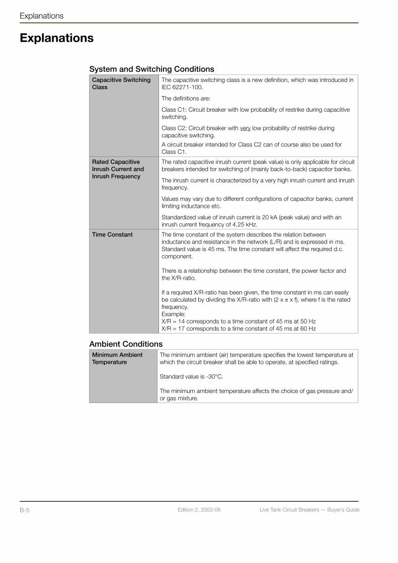
System and Switching ConditionsCapacitive Switching Class
The capacitive switching class is a new definition, which was introduced in IEC 62271-100.
The definitions are:
Class C1: Circuit breaker with low probability of restrike during capacitive switching.
Class C2: Circuit breaker with very low probability of restrike during capacitive switching.
A circuit breaker intended for Class C2 can of course also be used for Class C1.
Rated Capacitive Inrush Current and Inrush Frequency
The rated capacitive inrush current (peak value) is only applicable for circuit breakers intended for switching of (mainly back-to-back) capacitor banks.
The inrush current is characterized by a very high inrush current and inrush frequency.
Values may vary due to different configurations of capacitor banks, current limiting inductance etc.
Standardized value of inrush current is 20 kA (peak value) and with an inrush current frequency of 4.25 kHz.
Time Constant The time constant of the system describes the relation between inductance and resistance in the network (L/R) and is expressed in ms. Standard value is 45 ms. The time constant will affect the required d.c. component.
There is a relationship between the time constant, the power factor and the X/R-ratio.
If a required X/R-ratio has been given, the time constant in ms can easily be calculated by dividing the X/R-ratio with (2 x π x f), where f is the rated frequency.Example:X/R = 14 corresponds to a time constant of 45 ms at 50 HzX/R = 17 corresponds to a time constant of 45 ms at 60 Hz
Ambient Conditions Minimum Ambient Temperature
The minimum ambient (air) temperature specifies the lowest temperature at which the circuit breaker shall be able to operate, at specified ratings.
Standard value is -30°C.
The minimum ambient temperature affects the choice of gas pressure and/or gas mixture.

Live Tank Circuit Breakers — Buyer´s GuideB-5 Edition 2, 2003-06 Live Tank Circuit Breakers — Buyer´s Guide B-6Edition 2, 2003-06
Explanations
Ambient Conditions Maximum Ambient Temperature
The maximum ambient (air) temperature specifies the highest temperature at which the circuit breaker shall be able to operate, at specified ratings.
The maximum ambient temperature can affect the continuous current carrying capability.
Standard value is +40°C.
Altitude If height above sea level (a.s.l.) >1000 m the external dielectric strength is reduced due to lower density of air. Correction factor according to standard has to be used for external insulation.
Creepage Distance The creepage distance is defined as the shortest distance along the surface of an insulator between two conductive parts.
The required creepage distance is specified by the user in:- mm (total creepage distance)
- mm/kV (creepage distance in relation to the rated voltage).
Pollution Level Environmental conditions, with respect to pollution, are sometimes categorized in pollution levels. Four pollution levels are described in IEC 60815.
There is a relation between each pollution level and a corresponding minimum nominal specific creepage distance.
Pollution level Creepage distance
I - Light 16 mm/kVII - Medium 20 mm/kVIII - Heavy 25 mm/kVIV - Very Heavy 31 mm/kV
Ice Class If applicable, outdoor switchgear may be assigned to withstand a specified ice coating. Three classes exist in IEC:
- 1 mm of ice coating- 10 mm of ice coating- 20 mm of ice coating
Wind Load The specified wind loads for circuit breakers intended for outdoor normal conditions are based on a wind speed of 34 m/s.
DesignSingle- or Three-Pole Operation
For single-pole operation (1-pole operation), each individual pole of the circuit breaker is operated by its own operating mechanism. This makes single-phase as well as three-phase auto-reclosing possible.
For three-pole operation, (ganged operation), (3-pole operation) all three poles are operated by a common operating mechanism. The three poles are mechanically linked together for three-phase auto-reclosing.
(Two-pole operation (2-pole operation) applies only for special applica-tions, i.e. railway systems.)
Trip-free Circuit Breaker
A circuit breaker which can perform a complete opening operation, even if the trip command is activated during a closing operation and with the closing command maintained.NOTE! To ensure proper breaking of the current that may be established, it may be necessary that the contacts momentarily reach the closed position.
Fixed Trip A circuit breaker that cannot be released except when it is in the closed position.
Live Tank Circuit Breakers — Buyer´s GuideB-7 Edition 2, 2003-06 Live Tank Circuit Breakers — Buyer´s Guide B-8Edition 2, 2003-06
Explanations
Explanations
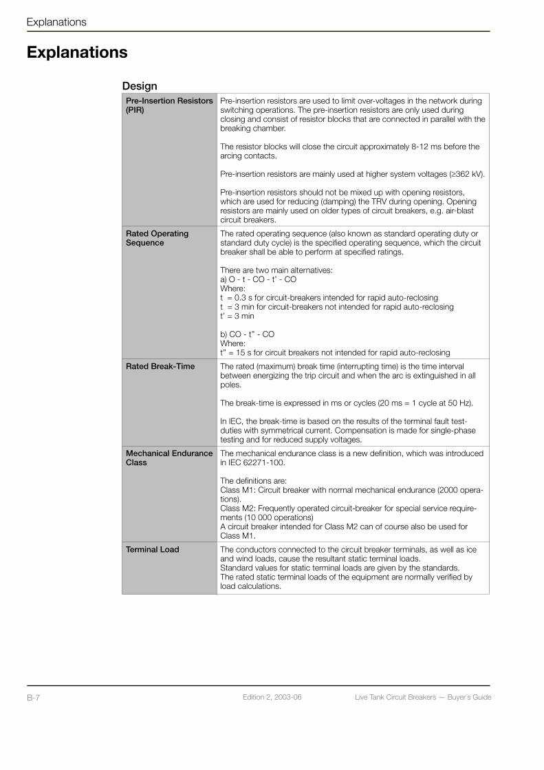
DesignPre-Insertion Resistors(PIR)
Pre-insertion resistors are used to limit over-voltages in the network during switching operations. The pre-insertion resistors are only used during closing and consist of resistor blocks that are connected in parallel with the breaking chamber. The resistor blocks will close the circuit approximately 8-12 ms before the arcing contacts.
Pre-insertion resistors are mainly used at higher system voltages (≥362 kV).
Pre-insertion resistors should not be mixed up with opening resistors, which are used for reducing (damping) the TRV during opening. Opening resistors are mainly used on older types of circuit breakers, e.g. air-blast circuit breakers.
Rated Operating Sequence
The rated operating sequence (also known as standard operating duty or standard duty cycle) is the specified operating sequence, which the circuit breaker shall be able to perform at specified ratings.
There are two main alternatives:a) O - t - CO - t’ - COWhere:t = 0.3 s for circuit-breakers intended for rapid auto-reclosingt = 3 min for circuit-breakers not intended for rapid auto-reclosingt’ = 3 min
b) CO - t’’ - COWhere:t’’ = 15 s for circuit breakers not intended for rapid auto-reclosing
Rated Break-Time The rated (maximum) break time (interrupting time) is the time interval between energizing the trip circuit and when the arc is extinguished in all poles.
The break-time is expressed in ms or cycles (20 ms = 1 cycle at 50 Hz).
In IEC, the break-time is based on the results of the terminal fault test-duties with symmetrical current. Compensation is made for single-phase testing and for reduced supply voltages.
Mechanical Endurance Class
The mechanical endurance class is a new definition, which was introduced in IEC 62271-100.
The definitions are:Class M1: Circuit breaker with normal mechanical endurance (2000 opera-tions). Class M2: Frequently operated circuit-breaker for special service require-ments (10 000 operations)A circuit breaker intended for Class M2 can of course also be used for Class M1.
Terminal Load The conductors connected to the circuit breaker terminals, as well as ice and wind loads, cause the resultant static terminal loads. Standard values for static terminal loads are given by the standards. The rated static terminal loads of the equipment are normally verified by load calculations.

Live Tank Circuit Breakers — Buyer´s GuideB-7 Edition 2, 2003-06 Live Tank Circuit Breakers — Buyer´s Guide B-8Edition 2, 2003-06
Explanations
DesignPressure Gas pressures can be expressed in several units, such as MPa, bar, P.s.i
etc.
1MPa = 106 Pa = 10 bar = 145 P.s.i
Rated filling pressureThe rated filling pressure is given at the reference temperature of +20°C and may be expressed in relative or absolute terms. The rated filling pres-sure is the pressure to which the circuit breaker is filled before being put into service.
Alarm pressureThe alarm pressure is given at the reference temperature of +20°C and may be expressed in relative or absolute terms. The alarm pressure is the pressure at which a monitoring (alarm) signal indicates that replenishment is necessary in a relatively short time.
Minimum pressure (Lock out, interlocking or blocking pressure)The minimum pressure is given at the reference temperature of +20°C and may be expressed in relative or absolute terms. The minimum pressure is the pressure at which the circuit breaker becomes interlocked for further operation and when replenishment is necessary.All type tests, except mechanical endurance test, are performed at this pressure.
Maximum pressureThe maximum pressure is given at the reference temperature of +20°C and may be expressed in relative or absolute terms. The maximum pressure is the pressure at which the circuit breaker is carrying its normal current at maximum ambient temperature.
Operation and ControlOperating mechanism - Control CubicleControl Voltage Control voltage is a DC supply used for the control circuits such as:
Close circuit and trip circuits etc.
Common rated control voltages:110, 125, 220 or 240 V DC(Less common rated control voltages: 250, 60 or 48 V DC)
The operating mechanism, including the control circuit, is designed for a rated control voltage but must additionally have operational capability throughout a specific voltage range to accommodate variations in supply voltage. The following required voltage ranges are required according to IEC:
Minimum voltage (auxiliary equipment): 85% of rated voltageMaximum voltage (auxiliary equipment): 110% of rated voltage
Minimum voltage (close circuit): 85% of rated voltageMaximum voltage (close circuit): 110% of rated voltage
Minimum voltage (trip circuit): 70% of rated voltageMaximum voltage (trip circuit): 110% of rated voltage

Live Tank Circuit Breakers — Buyer´s GuideB-9 Edition 2, 2003-06 Live Tank Circuit Breakers — Buyer´s Guide B-10Edition 2, 2003-06
Explanations
Explanations
Operation and ControlOperating mechanism - Control CubicleHeating Voltage /AC Auxiliary Voltage
AC Auxiliary voltage is an AC single-phase (phase – neutral) supply used for Heaters, Socket outlet and Lighting etc. when used.Normal values:110-127 V AC220-254 V AC
Motor Voltage Motor voltage is a DC supply or an AC single-phase (phase – neutral) supply for the spring charging motor.
Common rated motor voltages:110, 125, 220 and 240 V DC115, 120, 127, 230 and 240 V AC
The motor and the motor circuit are designed for a rated voltage but must additionally have operational capability throughout a specific voltage range to accommodate variations in supply voltage. The following required vol-tage range is required according to IEC:
Minimum voltage for motor circuit: 85% of rated voltageMaximum voltage for motor circuit: 110% of rated voltage
Closing Spring Charge Motor
The closing spring charging motor charges the closing spring after every closing operation.
Motor Contactor Motor contactor is controlled by the limit switch and starts / stops the closing spring charging motor.
Limit Switch The limit switch is monitoring the closing spring charging status.For operating mechanism BLK it can be of inductive or mechanical type. For operating mechanism BLG only mechanical type.
Auxiliary Contacts Auxiliary contacts are contacts that show the circuit breaker position. At least one contact is used in each control circuit (trip / close) to control the coil suppl. Contacts not used in control circuits, are normally connected to terminals for customer use. Normal total quantities:12 NO + 12 NC18 NO + 18 NC
Impulse ContactWiping Contact
A contact that gives an short impulse during contact movement.
NC-Contact
NO-Contact
NC-contact (normally closed contact) is a closed contact when device is not energized or in the drawn situation, according to circuit diagram.Could also be called: Break contact or b-contact.
NO-contact (normally open contact) is an open contact in the same situation.Could also be called: Make contact or a-contact.
NOC-contact (normally open-closed contact) is a closed contact that opens and an open contact that closes with a common backside when changing position.Could also be called: Change-over contact.
Trip / Close Switch The trip / close switch is used for control operations, when the local / remote (/ disconnected) switch is in local position.

Live Tank Circuit Breakers — Buyer´s GuideB-9 Edition 2, 2003-06 Live Tank Circuit Breakers — Buyer´s Guide B-10Edition 2, 2003-06
Explanations
Operation and ControlOperating mechanism - Control CubicleLocal / Remote / Disconnected Selector Switch
The local / remote / disconnected selector switch is used to switch between remote operating and local operating (via the open / close switch). It also has a disconnected position where operation is not possible. However a protection trip by-pass can be supplied that makes it possible to trip the circuit breaker. As an alternative a Local / Remote switch without disconnecting possibility can be provided.
Counter The counter is a non-resettable electro-mechanical counter that counts every close operation.
Anti-Pumping Relay The anti-pumping relay is a device that makes sure that there can be only one closing operation for each closing order.
MCB – Miniature Circuit Breaker
The MCB (Miniature Circuit Breaker) is a small automatic breaker that can be manually controlled or automatically tripped due to over current.The over current is either thermal (type K) or peak value (type B).1NO + 1NC auxiliary contacts, that shows MCB position, can be included.The MCB is normally used for AC auxiliary circuit (and motor circuit for operating mechanism type BLK)
Direct On Line Motor Starter
Direct On Line Motor Starter is a motor protection and manual control unit. This could also be an MCB (thermal controlled type).This unit trips the motor supply when motor overload occurs or when the Direct On Line Motor Starter is manually operated.
Operating Coils Close and trip coils in operating mechanisms BLK and BLG have relatively low power consumption, normally 200 W, due to a very good latch design.One close and two trip coils are supplied as standard. Additional close coils can be supplied as option. Also the second trip coil can be of the double type and additional trip circuit can be used.
Hand/Motor Switch The hand / motor switch disconnects the motor circuit during hand cran-king.The hand / motor switch, either manual or automatic, has the following functions: - Motor position; connects the motor-to-motor supply.- Hand position; short-circuit the motor to be used as a generator brake.
Heaters
Thermostat
Humidity Controller
Every operating mechanism has a continuous connected anti-condensa-tion heater of 70 W.In addition to that, one or more controlled heaters are fitted, depending on ambient temperature or humidity. These are controlled by a thermostat, or as an option, a humidity controller (a moisture detector controller).
Density Switch The density switch is a device that measures the gas pressure, ambient temperature compensated, inside the circuit breaker.The density switch includes normally: a scale display, one contact indica-ting the alarm pressure and two contacts controlling the gas-supervision interlocking relays at the blocking level.
Live Tank Circuit Breakers — Buyer´s GuideB-11 Edition 2, 2003-06 Live Tank Circuit Breakers — Buyer´s Guide B-12Edition 2, 2003-06
Explanations
Explanations
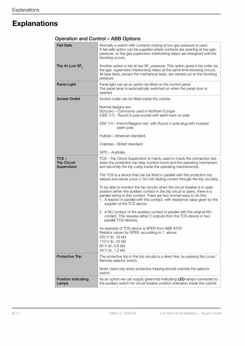
Operation and Control – ABB OptionsFail-Safe
Trip At Low SF6
Normally a switch with contacts closing at low gas-pressure is used.A fail-safe option can be supplied where contacts are opening at low gas-pressure, so the gas supervision interlocking relays are energized until the blocking occurs.
Another option is trip at low SF6-pressure. This option gives a trip order via the gas- supervision interlocking relays at the same time blocking occurs.All type tests, except the mechanical tests, are carried out at this blocking pressure.
Panel Light Panel light can as an option be fitted on the control panel. The panel lamp is automatically switched on when the panel door is opened.
Socket Outlet Socket outlet can be fitted inside the cubicle.
Normal designs are:Schucko – Commonly used in Northern Europe (CEE 7/7) Round 2-pole socket with earth-bars on side.
CEE 7/4 – French/Belgium std. with Round 2-pole plug with inverted earth-pole. Hubbel – American standard.
Crabtree – British standard.
GPO – Australia
TCS – Trip Circuit Supervision
TCS – Trip Circuit Supervision is mainly used to check the connection bet-ween the protection trip relay (control room) and the operating mechanism and secondly the trip coil(s) inside the operating mechanism(s).
The TCS is a device that can be fitted in parallel with the protection trip relay(s) and sends a low (< 50 mA) testing current through the trip circuit(s).
To be able to monitor the trip circuits when the circuit breaker is in open position (when the auxiliary contact in the trip circuit is open), there is a parallel wiring to this contact. There are two normal ways to do this:1. A resistor in parallel with this contact, with resistance value given by the supplier of the TCS device.
2. A NC-contact of the auxiliary contact in parallel with the original NO- contact. This requires either 2 outputs from the TCS-device or two parallel TCS-devices.
An example of TCS device is SPER from ABB ATCF.Resistor values for SPER, according to 1. above:220 V dc. 33 kΩ110 V dc. 22 kΩ60 V dc. 5,6 kΩ48 V dc. 1,2 kΩ
Protective Trip The protective trip in the trip circuits is a direct line, by-passing the Local / Remote selector switch. Note! Used only when protective tripping should override the selector switch.
Position Indicating Lamps
As an option we can supply green/red-indicating LED-lamps connected to the auxiliary switch for circuit breaker position indication inside the cubicle.

Live Tank Circuit Breakers — Buyer´s GuideB-11 Edition 2, 2003-06 Live Tank Circuit Breakers — Buyer´s Guide B-12Edition 2, 2003-06
Explanations
Operation and Control – ABB OptionsKey-Interlock Provision for key-interlock is mechanical (and electrical) interlocking
device, which interlocks the closing function, with a bracket suitable for installing the following brands: Castell, Kirk and Fortress.
Manual Trip Push-Button
69-Device
Manual mechanical trip push-button can on request be fitted on the inside or the outside of the operating mechanism.Note! Mechanical trip overrides SF6-blocking
An interlocking device, according to device No. 69 in the ANSI standard, that requires a resetting after each manual tripping before closing of the circuit breaker can be done.
Spring Charge Supervision
As an option a relay can be fitted to give an alarm when one or more of the errors / events below occurs:1. Loss of motor voltage.2. The direct on line motor starter is tripped manually.3. The direct on line motor starter is tripped due to over-current.4. An electrical error prevents spring charging.5. A mechanical error prevents spring charging.
The relay can be an auxiliary relay or with a time delay relay depending on alarm delaying possibility in the bay control unit. The alarm delay must be at least as long as the spring charging time, normally 15 s.
Voltage Supervision The circuits can be equipped with voltage supervision relay(s).This could be a zero-voltage relay (a standard auxiliary relay -not adjusta-ble) or voltage supervision relays (with adjustable setting for voltage and hysteresis).
Heater Supervision The heating circuit can be equipped with a current supervision relay (with adjustable setting for current and hysteresis) or an indicating lamp in series with the continuously connected heater.
Capacitor Tripping Trip circuits can be equipped with capacitor tripping devices.Used to automatically trip the circuit breaker at loss of, or at low operating voltage.The capacitor tripping device is always used together with a voltage super-vision relay (adjustable setting for voltage and hysteresis) that controls the tripping voltage level (one capacitor device / trip coil is required).
0-voltage Trip Coil The BLK operating mechanism can be equipped with 0-voltage Trip coil.It is used to automatically trip the circuit breaker at loss of, or low opera-ting voltage.The 0-voltage Trip coil is always used together with a voltage supervision relay (adjustable setting for voltage and hysteresis) that controls the trip-ping voltage level.
Fuses Fuses can be fitted in every circuit on request. Normal types:MCB – Miniature Circuit BreakerRed spot – Fuses (Links)UK 10,3-HESI – Fuses (Links)
Note! The trip circuits should preferably not include fuses.
Phase Discrepancy Phase discrepancy (Pole discordance) is a device that could be used on single pole operated circuit breakers, that uses auxiliary contacts to indicate that all phases are in the same position. When the poles are in different positions a time delay starts, and after a pre-set time, a trip order and alarm signal is normally initiated.
Live Tank Circuit Breakers — Buyer´s GuideB-13 Edition 2, 2003-06 Live Tank Circuit Breakers — Buyer´s Guide B-14Edition 2, 2003-06
Explanations
Explanations
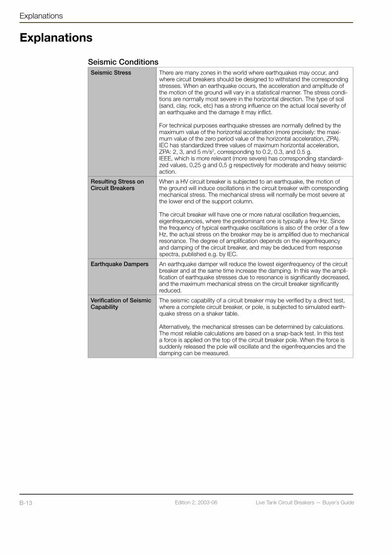
Seismic ConditionsSeismic Stress There are many zones in the world where earthquakes may occur, and
where circuit breakers should be designed to withstand the corresponding stresses. When an earthquake occurs, the acceleration and amplitude of the motion of the ground will vary in a statistical manner. The stress condi-tions are normally most severe in the horizontal direction. The type of soil (sand, clay, rock, etc) has a strong influence on the actual local severity of an earthquake and the damage it may inflict.
For technical purposes earthquake stresses are normally defined by the maximum value of the horizontal acceleration (more precisely: the maxi-mum value of the zero period value of the horizontal acceleration, ZPA). IEC has standardized three values of maximum horizontal acceleration, ZPA: 2, 3, and 5 m/s2, corresponding to 0.2, 0.3, and 0.5 g.IEEE, which is more relevant (more severe) has corresponding standardi-zed values, 0,25 g and 0,5 g respectively for moderate and heavy seismic action.
Resulting Stress on Circuit Breakers
When a HV circuit breaker is subjected to an earthquake, the motion of the ground will induce oscillations in the circuit breaker with corresponding mechanical stress. The mechanical stress will normally be most severe at the lower end of the support column.
The circuit breaker will have one or more natural oscillation frequencies, eigenfrequencies, where the predominant one is typically a few Hz. Since the frequency of typical earthquake oscillations is also of the order of a few Hz, the actual stress on the breaker may be is amplified due to mechanical resonance. The degree of amplification depends on the eigenfrequency and damping of the circuit breaker, and may be deduced from response spectra, published e.g. by IEC.
Earthquake Dampers An earthquake damper will reduce the lowest eigenfrequency of the circuit breaker and at the same time increase the damping. In this way the ampli-fication of earthquake stresses due to resonance is significantly decreased, and the maximum mechanical stress on the circuit breaker significantly reduced.
Verification of Seismic Capability
The seismic capability of a circuit breaker may be verified by a direct test, where a complete circuit breaker, or pole, is subjected to simulated earth-quake stress on a shaker table.
Alternatively, the mechanical stresses can be determined by calculations. The most reliable calculations are based on a snap-back test. In this test a force is applied on the top of the circuit breaker pole. When the force is suddenly released the pole will oscillate and the eigenfrequencies and the damping can be measured.

Live Tank Circuit Breakers — Buyer´s GuideB-13 Edition 2, 2003-06 Live Tank Circuit Breakers — Buyer´s Guide B-14Edition 2, 2003-06
Live Tank Circuit Breakers — Buyer´s GuideC-1 Edition 2, 2003-06 Live Tank Circuit Breakers — Buyer´s Guide C-2Edition 2, 2003-06
Puffer Products
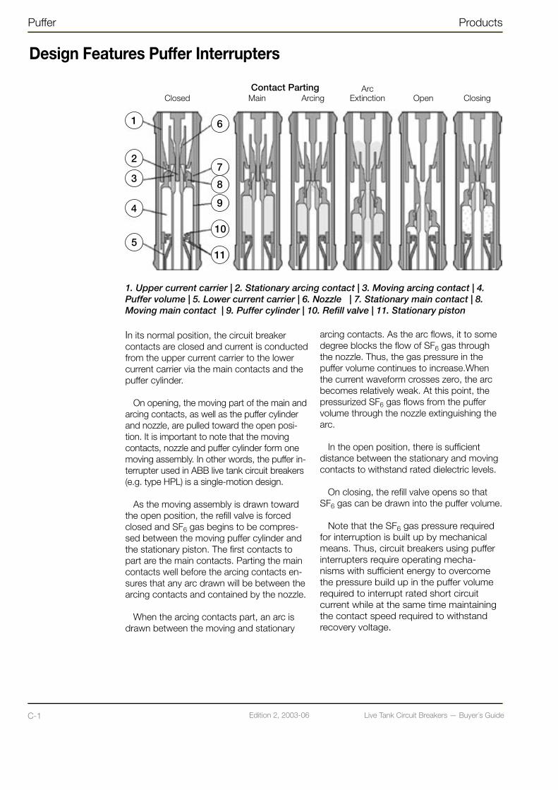
Design Features Puffer Interrupters
1. Upper current carrier | 2. Stationary arcing contact | 3. Moving arcing contact | 4. Puffer volume | 5. Lower current carrier | 6. Nozzle | 7. Stationary main contact | 8. Moving main contact | 9. Puffer cylinder | 10. Refill valve | 11. Stationary piston
In its normal position, the circuit breaker contacts are closed and current is conducted from the upper current carrier to the lower current carrier via the main contacts and the puffer cylinder.
On opening, the moving part of the main and arcing contacts, as well as the puffer cylinder and nozzle, are pulled toward the open posi-tion. It is important to note that the moving contacts, nozzle and puffer cylinder form one moving assembly. In other words, the puffer in-terrupter used in ABB live tank circuit breakers (e.g. type HPL) is a single-motion design.
As the moving assembly is drawn toward the open position, the refill valve is forced closed and SF6 gas begins to be compres-sed between the moving puffer cylinder and the stationary piston. The first contacts to part are the main contacts. Parting the main contacts well before the arcing contacts en-sures that any arc drawn will be between the arcing contacts and contained by the nozzle.
When the arcing contacts part, an arc is drawn between the moving and stationary
arcing contacts. As the arc flows, it to some degree blocks the flow of SF6 gas through the nozzle. Thus, the gas pressure in the puffer volume continues to increase.When the current waveform crosses zero, the arc becomes relatively weak. At this point, the pressurized SF6 gas flows from the puffer volume through the nozzle extinguishing the arc.
In the open position, there is sufficient distance between the stationary and moving contacts to withstand rated dielectric levels.
On closing, the refill valve opens so that SF6 gas can be drawn into the puffer volume.
Note that the SF6 gas pressure required for interruption is built up by mechanical means. Thus, circuit breakers using puffer interrupters require operating mecha-nisms with sufficient energy to overcome the pressure build up in the puffer volume required to interrupt rated short circuit current while at the same time maintaining the contact speed required to withstand recovery voltage.
Closed Main ArcingArc
Extinction Open ClosingContact Parting
1
2
3
4
5
6
7
8
9
10
11

Live Tank Circuit Breakers — Buyer´s GuideC-1 Edition 2, 2003-06 Live Tank Circuit Breakers — Buyer´s Guide C-2Edition 2, 2003-06
Design Features Auto-PufferTM Interrupters
Products Auto-Puffer
1. Upper current carrier | 2. Stationary arcing contact | 3. Moving arcing contact | 4. Auto-Puffer™ volume | 5. Puffer volume | 6. Refill valve | 7. Stationary piston | 8. Nozzle | 9. Stationary main contact | 10. Moving main contact | 11. Auto-puffer™ valve | 12. Puffer cylinder | 13. Over-pressure relief | 14. Lower current carrier
When interrupting high currents (e.g. rated short circuit current), Auto-Puffer™ interrupters show the advantage they were designed to provide.
On opening, the operation of an Auto-Puffer™ interrupter at high current begins the same way as a puffer interrupter. It is not until after arcing begins that a difference in the operation principle is seen between the high and low current interrupting cases.
When the arcing contacts part, an arc is drawn between the moving and stationary arcing contacts. As the arc flows, it to some degree blocks the flow of SF6 gas through the nozzle. The arc drawn is extremely hot and radiates a lot of heat and begins to heat the SF6 gas in the interrupting gas volume. Thus, the pressure inside the Auto-Puffer™ and puffer volumes increases due to the rise in temperature as well as due to the com-pression of gas between the puffer cylinder and stationary piston.
Gas pressure inside the Auto-Puffer™ volume continues to increase until it is high enough to force the Auto-Puffer™ valve to the closed position. All SF6 gas required for interruption is now trapped in the fixed Auto-Puffer™ volume and any further increase in gas pressure in that volume is due solely to heating from the arc. At about the same time, the gas pressure in the puffer volume reaches a level sufficient to push the overpressure valve open. Since the gas in the puffer volume escapes through the overpressure valve, there is no need for a high operating energy to overcome the compression of SF6 gas while at the same time maintaining the contact speed necessary to withstand recovery voltage.
When the current waveform crosses zero, the arc becomes relatively weak. At this point, the pressurized SF6 gas flows from the Auto-Puffer™ volume through the nozzle extinguishing the arc.
Closed Main ArcingValve
OperationArc
Extinction OpenContact Parting
1
2
3
4
5
6
7
8
9
10
11
13
14
12

Live Tank Circuit Breakers — Buyer´s GuideC-3 Edition 2, 2003-06 Live Tank Circuit Breakers — Buyer´s Guide D-1Edition 2, 2003-06
Auto-Puffer Products
Design Features Auto-PufferTM Interrupters
When interrupting low currents, Auto-Puffer™ interrupters act in much the same way as puffer interrupters. That is, there is not sufficient gas pressure generated to force the Auto-Puffer™ valve closed. Thus, the fixed Auto-Puffer™ volume and puffer volume form one large puffer volume. In such a case, the SF6 gas pressure required for interruption is built up by mechanical means as in a puffer interrupter. Unlike a puffer interrupter, however, Auto-Puffers™ need only mechanically generate sufficient gas pressure to interrupt a portion of the rated short circuit current (i.e. 20% to 30%)
In the open position, there is sufficient distance between the stationary and moving
contacts to withstand rated dielectric levels.On closing, the refill valve opens so that
SF6 gas can be drawn into the Auto-Puffer™ and puffer volumes.Because interruption of low currents requires only moderate build up of SF6 gas pressure by mechanical means and since high current interruption uses heating from the arc to generate necessary gas pressure in a fixed volume, Auto-Puffer™ interrupters require far less operating energy than puffer interrupters (i.e. about 50% less).
ABB Auto-Puffer™ interrupter is also a single motion design.
Live Tank Circuit Breakers — Buyer´s GuideC-3 Edition 2, 2003-06 Live Tank Circuit Breakers — Buyer´s Guide D-1Edition 2, 2003-06
Prodcuts LTB Circuit Breaker Family
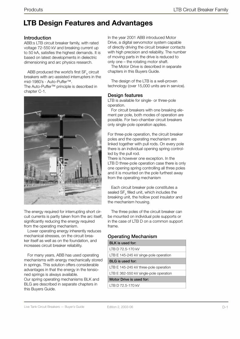
IntroductionABB:s LTB circuit breaker family, with rated voltage 72-550 kV and breaking current up to 50 kA, satisfies the highest demands. It is based on latest developments in dielectric dimensioning and arc physics research.
ABB produced the world’s first SF6 circuit breakers with arc-assisted interrupters in the mid-1980’s - Auto-Puffer™. The Auto-Puffer™ principle is described in chapter C-1.
The energy required for interrupting short cir-cuit currents is partly taken from the arc itself, significantly reducing the energy required from the operating mechanism.
Lower operating energy inherently reduces mechanical stresses, on the circuit brea-ker itself as well as on the foundation, and increases circuit breaker reliability.
For many years, ABB has used operating mechanisms with energy mechanically stored in springs. This solution offers considerable advantages in that the energy in the tensio-ned springs is always available. Our spring operating mechanisms BLK and BLG are described in separate chapters in this Buyers Guide.
LTB Design Features and Advantages
In the year 2001 ABB introduced Motor Drive, a digital servomotor system capable of directly driving the circuit breaker contacts with high precision and reliability. The number of moving parts in the drive is reduced to only one – the rotating motor shaft.
The Motor Drive is described in separate chapters in this Buyers Guide.
The design of the LTB is a well-proven technology (over 15,000 units are in service).
Design featuresLTB is available for single- or three-pole operation.
For circuit breakers with one breaking ele-ment per pole, both modes of operation are possible. For two-chamber circuit breakers only single-pole operation applies. For three-pole operation, the circuit breaker poles and the operating mechanism are linked together with pull rods. On every pole there is an individual opening spring control-led by the pull rod. There is however one exception. In the LTB D three-pole operation case there is only one opening spring controlling all three poles and it is mounted on the pole furthest away from the operating mechanism
Each circuit breaker pole constitutes a sealed SF6 filled unit, which includes the breaking unit, the hollow post insulator and the mechanism housing.
The three poles of the circuit breaker can be mounted on individual pole supports or in the case of LTB D on a common support frame.
Operating MechanismBLK is used for:
LTB D 72.5-170 kV
LTB E 145-245 kV singe-pole operation
BLG is used for:
LTB E 145-245 kV three-pole operation
LTB E 362-550 kV single-pole operation
Motor Drive is used for:
LTB D 72.5-170 kV

Live Tank Circuit Breakers — Buyer´s GuideD-2 Edition 2, 2003-06 Live Tank Circuit Breakers — Buyer´s Guide D-3Edition 2, 2003-06
• Since the interrupting capability is dependent on the density of the SF6 gas, the LTB circuit breaker is provided with a density monitor.The density monitor consists of a temperature compensated pressure switch. Therefore, alarm signal and blocking function are activated only if the pressure drops due to leakage.
The design corresponds with the demands in the standards IEC and ANSI. Special design solutions to meet other standards and/or specifications are also available.
LTB Circuit Breaker Family Products
LTB Design Features and Advantages
The operational reliability and the service life of an SF6 circuit breaker is very much dependent on the ability to ensure sealing of the SF6 gas volume and to neutralize the effects of moisture and decomposition products in the gas.
• The risk for gas leakage is negligible; double nitrile rubber O-rings and X-rings are used with excellent result.
• Each breaking unit is provided with a desiccant which absorbs the moisture and the decomposition products from the interruption process
Circuit Breaker type LTB D
1. Breaking Chamber
2. Support Insulator
3. Support Structure
4. Operating Mechanism type BLK
5. Trip Spring
6. Gas Tube with Protective Beam
7. Gas Supervision (On opposite side)
8. Drilled Holes for Connection to Ground
9. Pullrod with Protective Tube
10. Position Indicator
Live Tank Circuit Breakers — Buyer´s GuideD-2 Edition 2, 2003-06 Live Tank Circuit Breakers — Buyer´s Guide D-3Edition 2, 2003-06
Products LTB Circuit Breaker Family
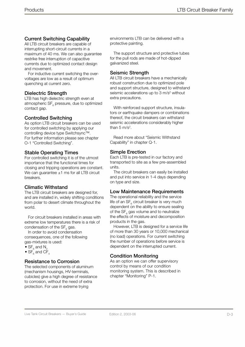
Current Switching CapabilityAll LTB circuit breakers are capable of interrupting short-circuit currents in a maximum of 40 ms. We can also guarantee restrike free interruption of capacitive currents due to optimized contact design and movement.
For inductive current switching the over-voltages are low as a result of optimum quenching at current zero.
Dielectric StrengthLTB has high dielectric strength even at atmospheric SF6 pressure, due to optimized contact gap.
Controlled SwitchingAs option LTB circuit breakers can be used for controlled switching by applying our controlling device type Switchsync™.For further information please see chapter O-1 “Controlled Switching”.
Stable Operating TimesFor controlled switching it is of the utmost importance that the functional times for closing and tripping operations are constant. We can guarantee ±1 ms for all LTB circuit breakers.
Climatic WithstandThe LTB circuit breakers are designed for, and are installed in, widely shifting conditions from polar to desert climate throughout the world.
For circuit breakers installed in areas with extreme low temperatures there is a risk of condensation of the SF6 gas.
In order to avoid condensation consequences, one of the following gas-mixtures is used: • SF6 and N2 • SF6 and CF4
Resistance to CorrosionThe selected components of aluminum (mechanism housings, HV-terminals, cubicles) give a high degree of resistance to corrosion, without the need of extra protection. For use in extreme trying
environments LTB can be delivered with a protective painting.
The support structure and protective tubes for the pull rods are made of hot-dipped galvanized steel.
Seismic StrengthAll LTB circuit breakers have a mechanically robust construction due to optimized pole and support structure, designed to withstand seismic accelerations up to 3 m/s2 without extra precautions.
With reinforced support structure, insula-tors or earthquake dampers or combinations thereof, the circuit breakers can withstand seismic accelerations considerably higher than 5 m/s2.
Read more about “Seismic Withstand Capability” in chapter Q-1.
Simple ErectionEach LTB is pre-tested in our factory and transported to site as a few pre-assembled units.
The circuit breakers can easily be installed and put into service in 1-4 days depending on type and size.
Low Maintenance RequirementsThe operational reliability and the service life of an SF6 circuit breaker is very much dependent on the ability to ensure sealing of the SF6 gas volume and to neutralize the effects of moisture and decomposition products in the gas.
However, LTB is designed for a service life of more than 30 years or 10,000 mechanical (no load) operations. For current switching the number of operations before service is dependent on the interrupted current.
Condition MonitoringAs an option we can offer supervisory control by means of our condition monitoring system. This is described in chapter “Monitoring” P-1.

Live Tank Circuit Breakers — Buyer´s GuideE-1 Edition 2, 2003-06 Live Tank Circuit Breakers — Buyer´s Guide E-2Edition 2, 2003-06
HPL Circuit Breaker Family Products
IntroductionABB:s HPL circuit breaker family with rated voltage 72-800 kV and breaking current up to 63 (80) kA, satisfies the highest demands. It is based on latest developments in dielectric dimensioning and arc physics research.
ABB has produced SF6 circuit breakers with Puffer interrupters since 1981. The Puffer principle is described in chapter C-1.
The HPL circuit breaker is operated by the motor charged spring operating mechanism type BLG which is described in separate chapters in this Buyer’s Guide.
The design of the HPL is a well-proven technology (over 11,000 units are in service)
Design featuresHPL can be single- or three-pole operated.
For circuit breakers with one breaking ele-ment per pole, both modes of operation are possible. For multi chamber circuit breakers only one-pole operation applies.
The three poles of the circuit breaker are mounted on individual pole supports. For three-pole operation, the breaker poles and the operating mechanism are linked together with pull rods. Each circuit breaker pole has its own individual opening spring.
Each circuit breaker pole constitutes a sealed SF6 filled unit, which includes the breaking unit, the hollow post insulator and the mechanism housing.
The operational reliability and the service life of an SF6 circuit breaker is very much dependent on the ability to ensure sealing of the SF6 gas volume and to neutralize the effects of moisture and decomposition pro-ducts in the gas.
• The risk for gas leakage is negligible; double nitrile rubber O-rings and X-rings are used with excellent result.
• Each breaking unit is provided with a desiccant which absorbs the moisture and the decomposition products from the interruption process
• Since the interrupting capability is dependent on the density of the SF6 gas, the HPL circuit breaker pole is provided with a density monitor.The density monitor consists of a temperature compensated pressure switch. Therefore, alarm signal and blocking function are activated only if the pressure drops due to leakage.
The design corresponds with the demands in the standards IEC and ANSI. Special design solutions to meet other standards and/or specifications are also available.
Current Switching CapabilityAll HPL circuit breakers are capable of interrupting short-circuit currents in a maximum of 40 ms. We can also guarantee interruption of capacitive currents with very low propability of restrike due to optimized contact design and movement.
For inductive current switching the over-voltages are low as a result of optimum quenching at current zero.
HPL Design Features and Advantages
Live Tank Circuit Breakers — Buyer´s GuideE-1 Edition 2, 2003-06 Live Tank Circuit Breakers — Buyer´s Guide E-2Edition 2, 2003-06
Prodcuts HPL Circuit Breaker Family
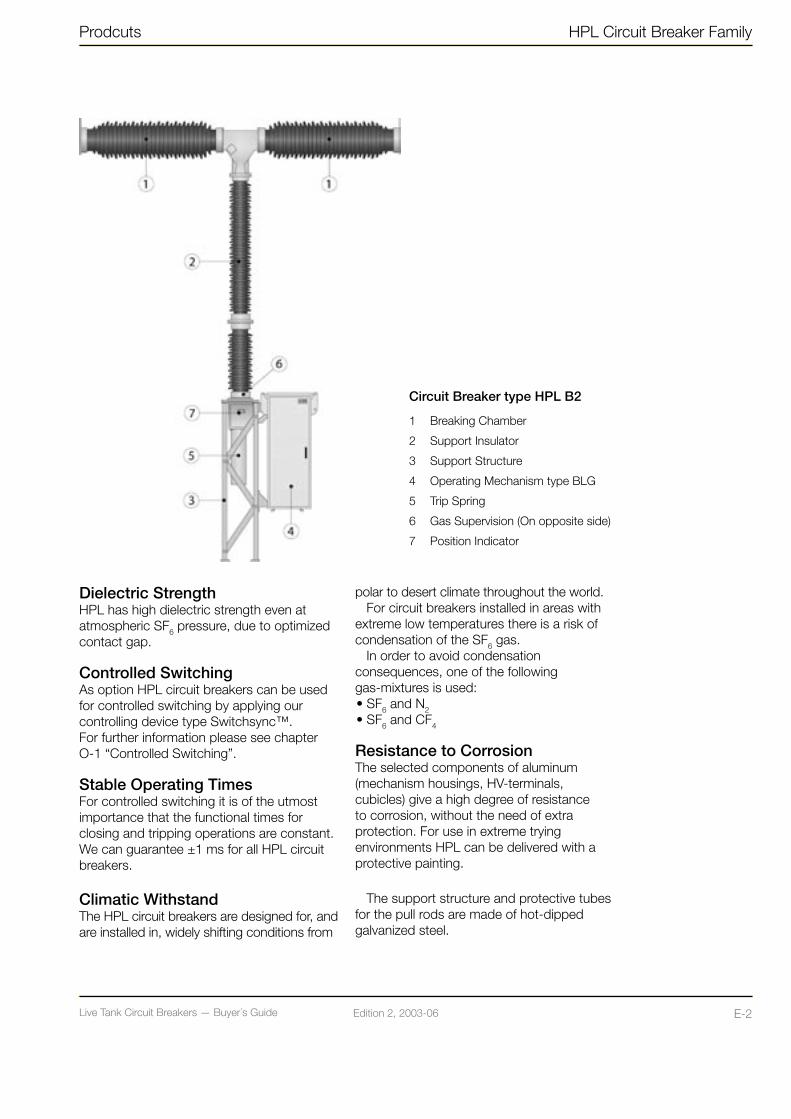
Circuit Breaker type HPL B2
1 Breaking Chamber
2 Support Insulator
3 Support Structure
4 Operating Mechanism type BLG
5 Trip Spring
6 Gas Supervision (On opposite side)
7 Position Indicator
Dielectric StrengthHPL has high dielectric strength even at atmospheric SF6 pressure, due to optimized contact gap.
Controlled SwitchingAs option HPL circuit breakers can be used for controlled switching by applying our controlling device type Switchsync™.For further information please see chapter O-1 “Controlled Switching”.
Stable Operating TimesFor controlled switching it is of the utmost importance that the functional times for closing and tripping operations are constant. We can guarantee ±1 ms for all HPL circuit breakers.
Climatic WithstandThe HPL circuit breakers are designed for, and are installed in, widely shifting conditions from
polar to desert climate throughout the world.For circuit breakers installed in areas with
extreme low temperatures there is a risk of condensation of the SF6 gas.
In order to avoid condensation consequences, one of the following gas-mixtures is used: • SF6 and N2 • SF6 and CF4
Resistance to CorrosionThe selected components of aluminum (mechanism housings, HV-terminals, cubicles) give a high degree of resistance to corrosion, without the need of extra protection. For use in extreme trying environments HPL can be delivered with a protective painting.
The support structure and protective tubes for the pull rods are made of hot-dipped galvanized steel.

Live Tank Circuit Breakers — Buyer´s GuideE-3 Edition 2, 2003-06 Live Tank Circuit Breakers — Buyer´s Guide F-1Edition 2, 2003-06
HPL Circuit Breaker Family Products
HPL Design Features and Advantages
Seismic StrengthAll HPL circuit breakers have a mechanically robust construction due to optimized pole and structure, designed to withstand seismicaccelerations up to 3 m/s2 without extra precautions.
With reinforced support structure, insula-tors or earthquake dampers or combinations thereof, the circuit breakers can withstand seismic accelerations considerably higher than 5 m/s2.
Read more about “Seismic Withstand Capability” in chapter Q-1.
Simple ErectionEach HPL is pre-tested in our factory and transported to site as a few pre-assembled units.
The circuit breakers can easily be installed
and put into service in 1-4 days depending on type and size.
Low Maintenance RequirementsThe operational reliability and the service life of an SF6 circuit breaker is very much dependent on the ability to ensure sealing of the SF6 gas volume and to neutralize the effects of moisture and decomposition products in the gas.However, LTB is designed for a service life of more than 30 years or 10,000 mechanical (no load) operations. For current switching the number of operations before service is dependent on the interrupted current.
Condition MonitoringAs option we can offer supervisory control by means of our condition monitoring system. This is described in chapter “Monitoring” P-1.
Live Tank Circuit Breakers — Buyer´s GuideE-3 Edition 2, 2003-06 Live Tank Circuit Breakers — Buyer´s Guide F-1Edition 2, 2003-06
BLK Design Features and Advantages
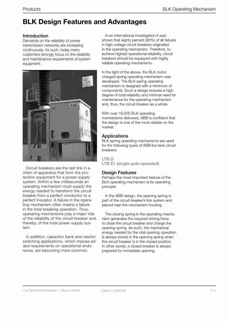
IntroductionDemands on the reliability of power transmission networks are increasing continuously. As such, today many customers strongly focus on the reliability and maintenance requirements of system equipment.
Circuit breakers are the last link in a chain of apparatus that form the pro-tection equipment for a power supply system. Within a few milliseconds an operating mechanism must supply the energy needed to transform the circuit breaker from a perfect conductor to a perfect insulator. A failure in the opera-ting mechanism often means a failure in the total breaking operation. Thus, operating mechanisms play a major role of the reliability of the circuit breaker and, thereby, of the total power supply sys-tem.
In addition, capacitor bank and reactor switching applications, which impose ad-ded requirements on operational endu-rance, are becoming more common.
In an international investigation it was shown that eighty percent (80%) of all failures in high voltage circuit breakers originated in the operating mechanism. Therefore, to achieve highest operational reliability, circuit breakers should be equipped with highly reliable operating mechanisms. In the light of the above, the BLK motor charged spring operating mechanism was developed. The BLK spring operating mechanism is designed with a minimum of components. Such a design ensures a high degree of total reliability and minimal need for maintenance for the operating mechanism and, thus, the circuit breaker as a whole.
With over 16,000 BLK operating mechanisms delivered, ABB is confident that the design is one of the most reliable on the market.
ApplicationsBLK spring operating mechanisms are used for the following types of ABB live tank circuit breakers:
LTB DLTB E1 (single-pole operated)
Design Features Perhaps the most important feature of the BLK operating mechanism is its operating principle.
In the ABB design, the opening spring is part of the circuit breaker’s link system and placed near the mechanism housing.
The closing spring in the operating mecha-nism generates the required driving force to close the circuit breaker and charge the opening spring. As such, the mechanical energy needed for the vital opening operation is always stored in the opening spring when the circuit breaker is in the closed position. In other words, a closed breaker is always prepared for immediate opening.
Products BLK Operating Mechanism

Live Tank Circuit Breakers — Buyer´s GuideF-2 Edition 2, 2003-06 Live Tank Circuit Breakers — Buyer´s Guide F-3Edition 2, 2003-06
Interlocking Against Unintentional OperationInterlocking is achieved partly electrically and partly mechanically. Electrical interlocking is achieved by having the circuits of the operation coils connected through the auxiliary contacts of the operating mechanism. In addition, the closing coil is connected through a limit switch that is controlled by the position of the spring drum. In this way the closing circuit is only closed when the breaker is in the open position and the closing springs are fully charged.
Based on the above interlocking design, the following operations are not possible when in service:• Closing operation when the breaker is
already closed (i.e. a “blind” stroke)• Closing operation during an opening
operation
BLK Housing • Corrosion resistant housing of painted
aluminum• Mechanical spring charge indicator - Located on the side of the housing - Visible with housing doors closed• Front and back doors equipped with
doorstops and provisions for padlock on door handles.
• Insulated doors and walls for low energy consumption and low noise level.
Immediately after each closing operation, a motor drives the spring charging gear to automatically charge the closing spring. After recharging the closing spring, the circuit breaker is capable of a rapid reclosing with a dead time interval of 0.3 s.
Both open and close springs are kept in the charged state by very reliable triple-ac-tion latches. The power unit is characterized by the fol-lowing robust main components:
• A spiral closing spring, which drives the operating lever of the circuit breaker.
• Robust, universal charging motor - Operates only after closing operation - Charges closing springs in ≤15 seconds
• Trip and close latches that are identical, fast acting and vibration proof.
• A damping device to retard the motion of the contact system at the end of an opening operation.
• A closed, oil-filled worm drive for a minimum of maintenance.
The auxiliary equipment is characterized by the following:
• Robust auxiliary contacts and limit switches.
• Mechanical indication of charged, partly charged or discharged closing spring.
• All electrical wiring used for external connections is brought to terminal blocks.
• Good accessibility through large housing and a hinged control panel.
Consistent operating times for all environmental conditions, making the circuit breaker very suitable for controlled switching.
BLK Design Features and Advantages
BLK Operating Mechanism Products

Live Tank Circuit Breakers — Buyer´s GuideF-2 Edition 2, 2003-06 Live Tank Circuit Breakers — Buyer´s Guide F-3Edition 2, 2003-06
PanelsBehind the front door there is a panel that may be equipped differently, depending on customer specific requirements. As a standard, the following equipment is included on the control panel:• Casing with instruction manual and final
drawings• Local open / close switch• Local / remote / disconnect selector switch• Electro-mechanical operations counter
– non-resettable• MCB (Miniature Circuit Breaker) for motor-
and AC auxiliary circuits
There is easy access to relays and contac-tors, which are placed on the rear side of the hinged control panel.
Behind the rear door of the operating mechanism housing there is an interface pa-nel containing all necessary terminal blocks for customer connections. Standard terminal blocks are compression type in which a bare wire is compressed between two metallic plates in the terminal.
Products BLK Operating Mechanism
ToolsA compartment for tools is located on the backside of the rear door.
Central Control Cubicle (CCC)When the circuit breaker is single-pole operated a Central Control Cubicle (CCC) is used when the circuit breaker is locally three-pole operated. The CCC will be delivered by ABB or arranged by the customer, from case to case. We are open for discussions how to arrange the solution.
Live Tank Circuit Breakers — Buyer´s GuideF-4 Edition 2, 2003-06 Live Tank Circuit Breakers — Buyer´s Guide F-5Edition 2, 2003-06
BLK — Operating principles
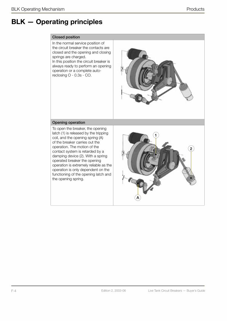
Closed position
In the normal service position of the circuit breaker the contacts are closed and the opening and closing springs are charged.In this position the circuit breaker is always ready to perform an opening operation or a complete auto-reclosing O - 0.3s - CO.
Opening operation
To open the breaker, the opening latch (1) is released by the tripping coil, and the opening spring (A) of the breaker carries out the operation. The motion of the contact system is retarded by a damping device (2). With a spring operated breaker the opening operation is extremely reliable as the operation is only dependent on the functioning of the opening latch and the opening spring.
BLK Operating Mechanism Products
1
2
A

Live Tank Circuit Breakers — Buyer´s GuideF-4 Edition 2, 2003-06 Live Tank Circuit Breakers — Buyer´s Guide F-5Edition 2, 2003-06
Products BLK Operating Mechanism
BLK — Operating principles
Closing Operation
Releasing of the closing latch (4) means an immediate response to close the circuit breaker. The driver lever (2) brings the eccentric guided closing lever (3) to the closed position. At the same time the opening spring (A) is charged. At the end of the stroke the closing lever (3) connected to the breaker is hooked up by the opening latch (1) in the closed position. Due to the eccentric guided lever (3) the driver lever (2) is declutched and continues to the resting position.
Charging of the Closing Spring
The circuit breaker has been closed. The motor circuit is closed by the limit switch (8). The motor (7) starts and charges the closing spring (6) as the main shaft (5) and the driver (2) are hooked up by the closing latch (4). When the closing spring is fully charged the limit switch will open the motor circuit. In case of emergency, the spring can be charged by means of the hand crank enclosed in the cubicle.
1
4A
2 3
6 2
8
75

Live Tank Circuit Breakers — Buyer´s GuideG-1 Edition 2, 2003-06 Live Tank Circuit Breakers — Buyer´s Guide G-2Edition 2, 2003-06
BLG Design Features and Advantages
IntroductionDemands on the reliability of power transmission networks are increasing continuously. As such, today many customers strongly focus on the reliability and maintenance requirements of system equipment.
Circuit breakers are the last link in a chain of apparatus that form the protection equip-ment for a power supply system. Within a few milliseconds an operating mechanism must supply the energy needed to transform the circuit breaker from a perfect conductor to a perfect insulator. A failure in the opera-ting mechanism often means a failure in the total breaking operation. Thus, operating mechanisms play a major role of the reliability of the circuit breaker and, thereby, of the total power supply system.
In addition, capacitor bank and reactor switching applications, which impose added requirements on operational endurance, are becoming more common.
In an international investigation it was shown that eighty percent (80%)of all failures in high voltage circuit breakers originated in the operating mechanism. Therefore, to achieve highest operational reliability, circuit breakers should be equipped with highly reliable operating mechanisms.
With over 40,000 BLG operating mecha-nisms delivered, ABB is confident that the design is one of the most reliable on the market. The design ensures a high degree of total reliability and minimal need for maintenance for the operating mechanism and, thus, the circuit breaker as a whole.
ApplicationsThe BLG spring operating mechanisms are used for the following types of circuit breaker:
HPL BLTB E1 (three-pole operated)LTB E2
Design FeaturesThe closing springs in the mechanism generate the required driving force to close the breaker and charge the opening spring.
The opening springs are part of the breaker’s link system and placed near the mechanism housing. This means that the mechanical energy needed for the vital opening operation is always stored in the opening spring when the breaker is in closed position. In other words, a closed breaker is always prepared for immediate opening.
A universal motor(s) drive(s) the spring charging gear, which automatically charges the closing springs immediately after each closing operation. The springs are kept in the charged state by a latch that is rele-ased when the breaker is being closed. This enables rapid reclosing of the breaker after a dead time interval of 0.3 s.
The principle of the operating mechanism can be briefly described as follows: an endless chain links a cam disc and a set of springs. The chain, which is in two loops and runs over a motor-driven sprocket, transmits energy when the springs are being charged and drives the cam disc around when the circuit breaker is to be closed. During its rotation the cam disc actuates a link that converts the rotating motion into a linear motion.
The trip and closing latches are identical, fast acting and vibration proof.
BLG Operating Mechanism Products

Live Tank Circuit Breakers — Buyer´s GuideG-1 Edition 2, 2003-06 Live Tank Circuit Breakers — Buyer´s Guide G-2Edition 2, 2003-06
A damping device is included to retard the motion of the contact system in the end positions.
The auxiliary equipment is characterized by the following:• Robust auxiliary contacts and limit
switches.• Mechanical indication of charged, partly
charged or discharged closing spring.• All electrical wiring used for external
connections is brought to terminal blocks.
Consistent operating times for all environ-mental conditions which make the circuit breaker suitable for controlled switching.
Interlocking Against Unintentional OperationInterlocking is achieved partly electrically and partly mechanically. Electrical interlocking is achieved by having the circuits of the operation coils connected through the auxiliary contacts of the operating mechanism. In addition, the closing coil is connected through a limit switch that is controlled by the position of the spring bridge. In this way the closing circuit is only closed when the breaker is in the open position and the closing springs are fully charged.
Based on the above interlocking design, the following operations are not possible when in service:• Closing operation when the breaker is
already closed (i.e. a “blind” stroke)• Closing operation during an opening
operation
BLG Housing • Corrosion resistant housing of painted
aluminum• Front and back doors equipped with
doorstops and provisions for padlock on door handles.
• Insulated doors and walls for low energy consumption and low noise level.
PanelsBelow the front door there is a panel, with a transparent shutter, that may be equipped differently, depending on customer specific requirements. As a standard, the following
equipment is included on the control panel:• Local open / close switch• Local / remote / disconnect selector switch• Electro-mechanical operations counter
– non-resettable • Mechanical spring charge indicator
– visible through the transparent shutter
Behind the rear door of the operating mechanism housing there is an interface pa-nel containing all necessary terminal blocks for customer connections. As a standard, the following equipment is included: • Standard terminal blocks of compression
type (in which a bare wire is compressed between two metallic plates in the terminal)
• Interlocking for hand spring charging• Control equipment – such as relays,
MCB’s, contactors etc.• Auxiliary contacts
On the backside of the rear door there is a compartment for documents with instruction manual and final drawings. A hand crank is also attached.
Central Control Cubicle (CCC)When the circuit breaker is single-pole operated a Central Control Cubicle (CCC) is used when the circuit breaker is locally three-pole operated. The CCC will be delivered by ABB or arranged by the customer, from case to case. We are open for discussions how to arrange the solution.
Products BLG Operating Mechanism
Live Tank Circuit Breakers — Buyer´s GuideG-3 Edition 2, 2003-06 Live Tank Circuit Breakers — Buyer´s Guide G-4Edition 2, 2003-06
BLG — Operating principles
Closed position
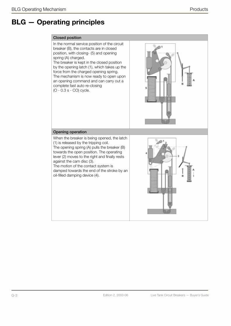
In the normal service position of the circuit breaker (B), the contacts are in closed position, with closing- (5) and opening spring (A) charged.The breaker is kept in the closed position by the opening latch (1), which takes up the force from the charged opening spring.The mechanism is now ready to open upon an opening command and can carry out a complete fast auto re-closing (O - 0.3 s - CO) cycle.
Opening operation
When the breaker is being opened, the latch (1) is released by the tripping coil.The opening spring (A) pulls the breaker (B) towards the open position. The operating lever (2) moves to the right and finally rests against the cam disc (3). The motion of the contact system is damped towards the end of the stroke by an oil-filled damping device (4).
BLG Operating Mechanism Products
Live Tank Circuit Breakers — Buyer´s GuideG-3 Edition 2, 2003-06 Live Tank Circuit Breakers — Buyer´s Guide G-4Edition 2, 2003-06
Products BLG Operating Mechanism
Closing operation
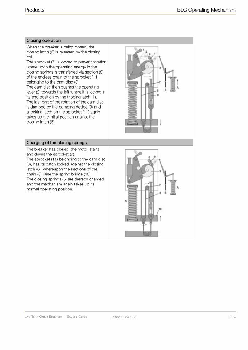
When the breaker is being closed, the closing latch (6) is released by the closing coil. The sprocket (7) is locked to prevent rotation where upon the operating energy in the closing springs is transferred via section (8) of the endless chain to the sprocket (11) belonging to the cam disc (3). The cam disc then pushes the operating lever (2) towards the left where it is locked in its end position by the tripping latch (1). The last part of the rotation of the cam disc is damped by the damping device (9) and a locking latch on the sprocket (11) again takes up the initial position against the closing latch (6).
Charging of the closing springs
The breaker has closed; the motor starts and drives the sprocket (7). The sprocket (11) belonging to the cam disc (3), has its catch locked against the closing latch (6), whereupon the sections of the chain (8) raise the spring bridge (10). The closing springs (5) are thereby charged and the mechanism again takes up its normal operating position.

Live Tank Circuit Breakers — Buyer´s GuideH-1 Edition 2, 2003-06 Live Tank Circuit Breakers — Buyer´s Guide H-2Edition 2, 2003-06
Motor Drive Design Features and Advantages
A revolutionary concept for the operation of high voltage circuit breakersThere is an increasing focus by power network operators to increase their operational returns on invested capital equipment. An important step in this direction is the shift towards condition-based maintenance in conjunction with utilizing a plant that has inherently low maintenance requirements.
ABB has concentrated its development on designing high performance, high-voltage equipment that requires minimum of mainte-nance. The development has consequently focused on systems which predict a fault before it occurs and a warning is sent out. The warning can be used to avoid unplanned service interruptions and maintenance jobs can be carried out according to the planned schedule.
LTB Circuit Breaker with ABB’s motor operated mechanism Motor Drive.
What is a Motor Drive?A Motor Drive is a digitally controlled motor directly moving the circuit breaker contacts.
ABB has developed a digital controlled servomotor system capable of direct driving circuit breaker contacts with high precision and reliability. The number of moving parts in the drive is reduced to just one – the rotating motor shaft.
ApplicationsAt present available for:LTB D
Design featuresMotor Drive is essentially a digital system. The required operating motions (trip & close) are digitally programmed into a Control unit.
On command, the required operations are executed according to the stored contact travel program and the motor is driven to move the circuit breaker primary contacts accordingly. Energy charging, buffering, release and transmission are essentially elec-trical and as such the mechanical system is reduced to one single moving part - the rotor of the Motor.
The inherent mechanical simplicity of Motor Drive provides major advantages:• Elimination of wearing components• Reduction in operating forces• Substantial reduction of the noise
level during operation• Inherent increased reliability by elimination
of multiple-interacting mechanical components
MD Motor Drive Operating Mechanism Products

Live Tank Circuit Breakers — Buyer´s GuideH-1 Edition 2, 2003-06 Live Tank Circuit Breakers — Buyer´s Guide H-2Edition 2, 2003-06
Products MD Motor Drive Operating Mechanism
The Motor Drive platform offers many advantages and new capabilities:
• Direct, active feedback control of contact motion
• Flexible permissive logic control of the circuit breaker
• Dramatic reduction of transients in substation auxiliary supply
• Increased operational security and improved asset management through advanced on-line monitoring
Robust Modular DesignThe Motor Drive is designed for widely shifting conditions from polar to desert climate.
ReliabilityA circuit breaker must operate safely and reliably at all times. This is further improved by:• Eliminated multiple-interacting
mechanical components. • Inherent self-monitoring capability.• Redundant critical systems.
Two independent voltage supplies. Automatic switching to back-up supply.
Motor Drive Control Cubicle• Corrosion resistant housing of painted
aluminum.• Front and back doors equipped with
doorstops and provisions for locking of door handles.
• Insulated doors and walls.
Control PanelBehind the front door is a panel that may be equipped differently, depending on customer specific requirements. As a standard, the following equipment is included on the control panel:• Casing with instruction manual and final
drawings• Local open / close control• Local / remote / disconnect selector
control• Electro-mechanical operations counter
– non-resettable• Indicators for charged/discharged
capacitors• Warning and alarm indicators• Contact position indicator• MCBs for voltage supplies, heaters and
socket outlet
Behind the rear door of the control cubicle housing there is an interface panel containing all necessary terminal blocks for customer connections.
Simple ErectionInstallation and commissioning is easy.Each motor drive is pre-tested together with the circuit breaker poles and shipped to installation site in the form of a few pre-assembled units.
Condition MonitoringFor service purposes the Motor Drive collects and stores a wide array of data that can be retrieved either locally or from the control board or remotely through a modem. In its basic design, the following information can be retrieved from the Motor Drive: • Position indication (open or closed)• Warnings and alarms • Energy level• Internal failure• Phase discrepancy (for one-pole
operation)

Live Tank Circuit Breakers — Buyer´s GuideH-3 Edition 2, 2003-06 Live Tank Circuit Breakers — Buyer´s Guide H-4Edition 2, 2003-06
Advantages• Only one moving part, simple and reliable
• Optimal pre-programmed travel curve
• Contact travel is compensated against ageing and changes in ambient temperature by the adaptive control system
• Condition monitoring is inherently possible without need for additional sensors
• Software controlled auxiliary contacts.
• Low power demand, no transient loads
• Low mechanical stress and low noise levels
• Modular design
• Redundant power supply inputs
• All connection to substation control on one programmable circuit board
• Serial communication port for external connection
• Fully optical interface is supported
• Micro-motion – functional test
• Can be used in combination with Switchsync™ applications (one-pole operation).
MD Motor Drive Operating Mechanism Products
Built in function test- Micro-motionTo obtain information about the condition of all the electrical and mechanical components in the system, the main contacts can be moved a short distance without separation. This can be executed automatically by a programmed order or by command via the service serial communication interface.
Motor Drive Design Features and Advantages
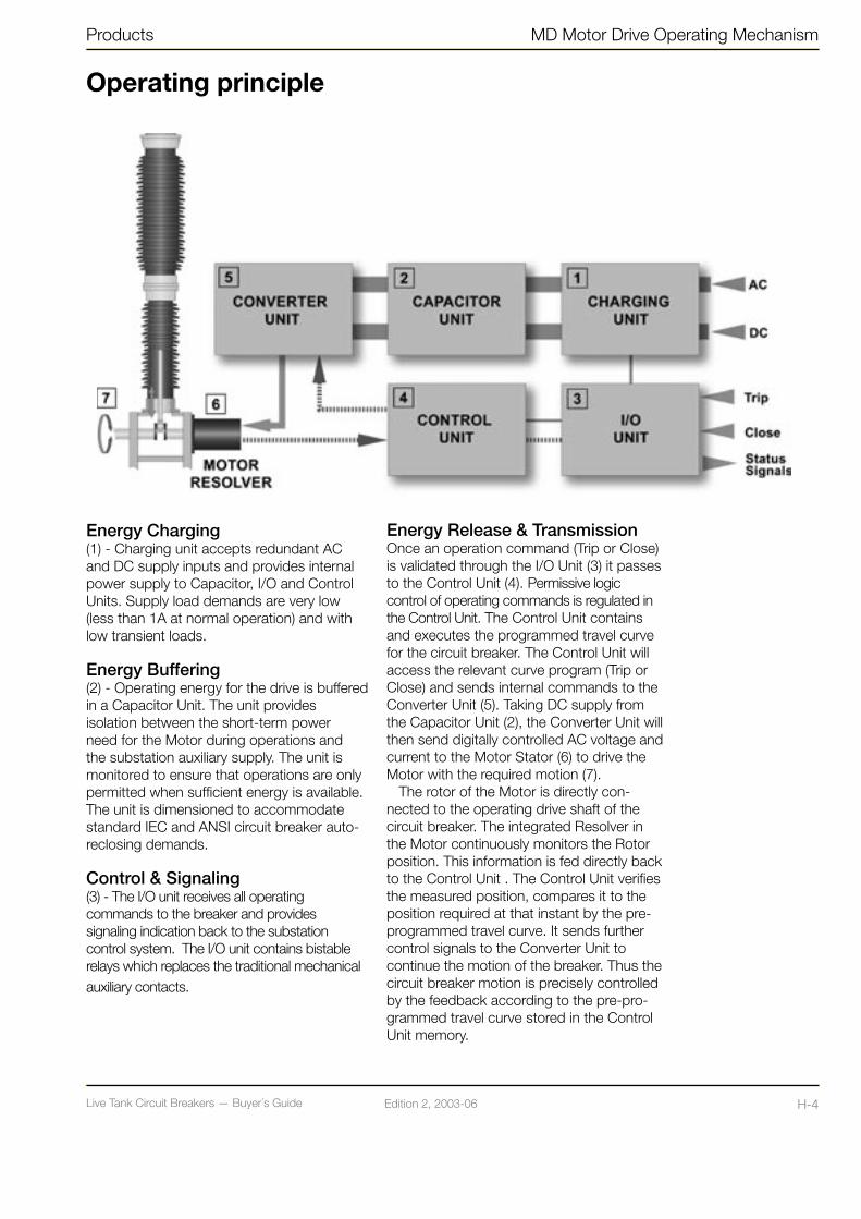
Live Tank Circuit Breakers — Buyer´s GuideH-3 Edition 2, 2003-06 Live Tank Circuit Breakers — Buyer´s Guide H-4Edition 2, 2003-06
Products MD Motor Drive Operating Mechanism
Operating principle
Energy Charging(1) - Charging unit accepts redundant AC and DC supply inputs and provides internal power supply to Capacitor, I/O and Control Units. Supply load demands are very low (less than 1A at normal operation) and with low transient loads.
Energy Buffering(2) - Operating energy for the drive is buffered in a Capacitor Unit. The unit provides isolation between the short-term power need for the Motor during operations and the substation auxiliary supply. The unit is monitored to ensure that operations are only permitted when sufficient energy is available. The unit is dimensioned to accommodate standard IEC and ANSI circuit breaker auto-reclosing demands.
Control & Signaling(3) - The I/O unit receives all operating commands to the breaker and provides signaling indication back to the substation control system. The I/O unit contains bistable relays which replaces the traditional mechanical auxiliary contacts.
Energy Release & TransmissionOnce an operation command (Trip or Close) is validated through the I/O Unit (3) it passes to the Control Unit (4). Permissive logic control of operating commands is regulated in the Control Unit. The Control Unit contains and executes the programmed travel curve for the circuit breaker. The Control Unit will access the relevant curve program (Trip or Close) and sends internal commands to the Converter Unit (5). Taking DC supply from the Capacitor Unit (2), the Converter Unit will then send digitally controlled AC voltage and current to the Motor Stator (6) to drive the Motor with the required motion (7).
The rotor of the Motor is directly con-nected to the operating drive shaft of the circuit breaker. The integrated Resolver in the Motor continuously monitors the Rotor position. This information is fed directly back to the Control Unit . The Control Unit verifies the measured position, compares it to the position required at that instant by the pre-programmed travel curve. It sends further control signals to the Converter Unit to continue the motion of the breaker. Thus the circuit breaker motion is precisely controlled by the feedback according to the pre-pro-grammed travel curve stored in the Control Unit memory.

Live Tank Circuit Breakers — Buyer´s GuideI-1 Edition 2, 2003-06 Live Tank Circuit Breakers — Buyer´s Guide I-2Edition 2, 2003-06
LTB Circuit Breaker Family Technical Information
Circuit Breakers type LTB D and LTB E
ABB produced the world’s first SF6 circuit breakers with arc-assisted interrupters in the mid-1980’s.
The energy required for interrupting short circuit currents is partly taken from the arc itself, significantly reducing the energy required from the operating mechanism.
Lower operating energy inherently reduces mechanical stresses and increases circuit-breaker reliability.
For many years, ABB has used operating mechanisms with energy mechanically stored in springs. This solution offers considerable advantages in that the energy in the tensioned springs is always available.
We are now also introducing the latest technology for circuit breaker operation – Motor Drive
Brief Performance Data:
Installation Outdoor / Indoor
Design SF6 Auto-Puffer™ interrupter Spring operating mechanisms orMotor Drive
Insulation SF6
Rated Voltage Up to 550 kV
Max. Rated Current Up to 4000 A
Max. Breaking Current Up to 50 kA
Max. Short-time Current Up to 50 kA/3 s
Insulators Composite or Porcelain
Creepage Distance 25 mm/kV (Longer on request)
Service Conditions:
Ambient Temperature -30 to +40 oC(Operation in tempe-ratures down to –55 or up to +70 oC on request)
Design Altitude 1000 m.a.s.l.(Higher altitudes on request)
Type of Operation Single- or Three-pole

Live Tank Circuit Breakers — Buyer´s GuideI-1 Edition 2, 2003-06 Live Tank Circuit Breakers — Buyer´s Guide I-2Edition 2, 2003-06
Technical Information LTB Circuit Breaker Family
MaterialThe selected components of aluminum (mechanism housings, HV-terminals, cubicles) give a high degree of resistance to corrosion, without the need of extra protection. For use in extreme trying environments LTB can be delivered with a protective painting.
The support structure and protective tubes for the pull rods are made of hot-dipped galvanized steel.
InsulatorsLTB circuit breaker is as standard delivered with insulators that consist of high-grade brown-glazed porcelain or composite insulators (light gray). LTB with light gray porcelain can be delivered on request.
LTB is available as standard with long creepage distances.
Longer creepage distances can be quoted on request.
More information about our composite insulators can be found in chapter N-1.
Mechanical StrengthThe mechanical durability gives a sufficient safety margin for normal wind loads and static and dynamic forces from conductors.
Seismic Withstand StrengthAll LTB circuit breakers can in their standard versions, withstand seismic accelerations up to 3 m/s2 (0,3 g) in accordance with IEC 1166 and IEEE 693.
For higher acceleration see chapter Q-1 “Seismic Withstand Capability”
Rating PlatesA rating plate, which includes data for the circuit breaker, is placed on the operating mechanism cubicle. The rating plate is made of stainless steel with engraved text.
Operating MechanismThe circuit breaker is operated by motor charged spring operating mechanism(s), which is installed in a compact splash proof and corrosion resistant housing, attached to the structure.
• One BLK is used for three-pole operation for LTB D 72.5 - 170 kV.Optionally Motor Drive can operate this type of LTB.
• Three BLK’s are used for single pole operation for LTB D 72.5 - 170 kV. Optionally Motor Drive can operate this type of LTB.
• Three BLK’s are used for single pole operation for LTB E up to 245 kV.
• One BLG is used for three-pole operation for LTB E up to 245 kV.
• Three BLG’s are used for single-pole operation for LTB E 420 - 550 kV.
More detailed information about the ope-rating mechanisms can be found in chapters F-1, G-1, K-1 and L-1 in this Buyer’s Guide.
Sealing Systems for SF6 VolumeThe sealing system consists of double nitrile rubber O-rings in all static seals and double X-rings in all dynamic seals.
This type of sealings has been used in our circuit breakers for more than 30 years with excellent service record at varying climatic conditions.
The SF6-gas leakage is less than 0,5% per year.
SF6 Density MonitoringSince the interrupting capability is dependent on the density of the SF6 gas, the LTB circuit breaker is provided with density monitor(s). The density monitor consists of a temperature compensated pressure switch. Therefore, alarm signal and blocking function are activated only if the pressure drops due to leakage.The standard version of LTB D for 72,5-170 kV has one common density monitor for all three poles.Alternatively LTB D can be provided with one density monitor per pole.
All LTB E circuit breakers have one density monitor per pole.
More information can be found in chapter B-1 “Explanations”.
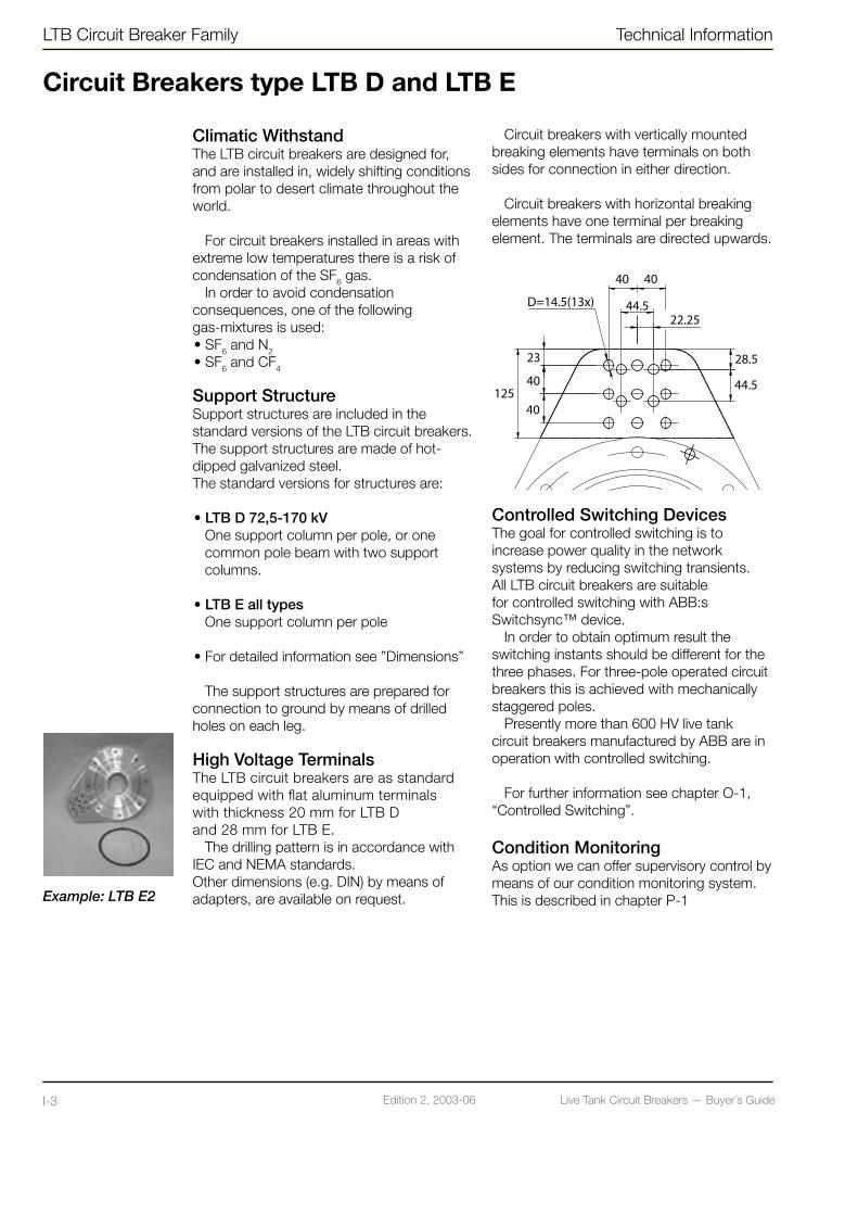
Live Tank Circuit Breakers — Buyer´s GuideI-3 Edition 2, 2003-06 Live Tank Circuit Breakers — Buyer´s Guide I-4Edition 2, 2003-06
LTB Circuit Breaker Family Technical Information
Circuit Breakers type LTB D and LTB E
Climatic WithstandThe LTB circuit breakers are designed for, and are installed in, widely shifting conditions from polar to desert climate throughout the world.
For circuit breakers installed in areas with extreme low temperatures there is a risk of condensation of the SF6 gas.
In order to avoid condensation consequences, one of the following gas-mixtures is used: • SF6 and N2 • SF6 and CF4
Support StructureSupport structures are included in the standard versions of the LTB circuit breakers. The support structures are made of hot-dipped galvanized steel. The standard versions for structures are:
• LTB D 72,5-170 kVOne support column per pole, or one common pole beam with two support columns.
• LTB E all typesOne support column per pole
• For detailed information see ”Dimensions”
The support structures are prepared for connection to ground by means of drilled holes on each leg.
High Voltage TerminalsThe LTB circuit breakers are as standard equipped with flat aluminum terminals with thickness 20 mm for LTB D and 28 mm for LTB E.
The drilling pattern is in accordance with IEC and NEMA standards. Other dimensions (e.g. DIN) by means of adapters, are available on request.
Circuit breakers with vertically mounted breaking elements have terminals on both sides for connection in either direction.
Circuit breakers with horizontal breaking elements have one terminal per breaking element. The terminals are directed upwards.
Controlled Switching DevicesThe goal for controlled switching is to increase power quality in the network systems by reducing switching transients. All LTB circuit breakers are suitable for controlled switching with ABB:s Switchsync™ device.
In order to obtain optimum result the switching instants should be different for the three phases. For three-pole operated circuit breakers this is achieved with mechanically staggered poles.
Presently more than 600 HV live tank circuit breakers manufactured by ABB are in operation with controlled switching.
For further information see chapter O-1, “Controlled Switching”.
Condition MonitoringAs option we can offer supervisory control by means of our condition monitoring system.This is described in chapter P-1
Example: LTB E2
Live Tank Circuit Breakers — Buyer´s GuideI-3 Edition 2, 2003-06 Live Tank Circuit Breakers — Buyer´s Guide I-4Edition 2, 2003-06
Technical Information LTB Circuit Breaker Family
Type TestsThe LTB circuit breakers have been type tested in accordance with IEC and/or ANSI standards. Type test reports can be presented on request.
Routine TestsAll LTB circuit breakers are routine tested before delivery. Our test program complies with IEC and ANSI standards.
For detailed information please see special chapter R-1 regarding “Quality Control and Testing”.
TransportThe LTB circuit breakers are normally packed and transported in seaworthy wooden crates.
The circuit breaker poles with one breaking element per pole are transported as com-plete units.
For circuit breakers with two breaking ele-ments per pole, the breaking elements and the support insulators are transported in two separate cases.
For detailed information regarding weights and dimensions see “Shipping data”.
Breaking elements as well as support insu-lators are filled with gas at a slight overpres-sure.
Arrival InspectionOn arrival the packaging and contents should be checked against packing list. In the event of damage to the goods, contact ABB for advice, before further handling of the goods takes place. Any damage ought to be documented (photographed).
Erection and CommissioningAssembly instructions are provided with each delivery.
Erection work at site can be done in 1-4 days depending on LTB type and size.
Filling of SF6-gas to specified rated pres-sure is done by using the following pressuri-zing equipment, which can be delivered on request:• One special control valve, for connection to
the gas bottle, and a 20 m gas-filled hose with connectors.
• A complementary control valve for connection to CF4 or N2 gas bottle (for mixed gas filling).
When using above equipment gas filling can be carried out without gas being rele-ased into the atmosphere.
For illustration of gas filling equipment see page I-6.
MaintenanceLTB is designed for a service life of more than 30 years or 10,000 mechanical operations. For current switching the number of operations before service is dependent on the interrupted current and type of application.
Inspection, maintenance and overhaul should be carried out at regular intervals de-pending on the ambient conditions and the number of operations.
The general actions are described below:
• 1-2 years: Ocular inspection
• 7-10 years or 2,000 mechanical operations: Extended ocular inspection and some lubrication of the operating mechanism(s)

Live Tank Circuit Breakers — Buyer´s GuideI-5 Edition 2, 2003-06 Live Tank Circuit Breakers — Buyer´s Guide I-6Edition 2, 2003-06
LTB Circuit Breaker Family Technical Information
• 15-20 years or 5,000 mechanical operations:Preventive maintenance including general inspection of the circuit breaker and operating mechanism. Operation test including measurement of operating times and possible adjustments.
• 30 years or 10,000 mechanical operations:A comprehensive inspection is recommended to give increased safety and continued problem-free operation. The inspection methods and scope depend very much on the local conditions.
For circuit breakers for special switching duties such as switching of reactor banks overhaul of the breaking chamber should be carried out more frequently, approximately 5,000 operations.
Overhaul and repair work must be performed by authorized personnel only.
The instructions in the manual for operation and maintenance should be observed.
ABB is available for discussions and advice.
Recommended Spare PartsHigh operation frequency (e.g. circuit breakers for reactor or capacitor switching) and/or large quantities of circuit breakers:• Complete poles• Complete operating mechanisms• Sets of contacts• Sets of gaskets• Density switches• SF6-gas
Spare parts for the operating mechanisms BLK and BLG; see chapter K-1 and L-1
SF6-gasGas for filling up to rated pressure can be delivered in bottles, each containing 40 kg gas.
The quantity required for each type of LTB varies from one circuit breaker type to an-other. This information is given in the tender.
The pressurizing equipment can be de-livered on request, and is described under “Erection and Commissioning”.
Brackets and Primary ConnectionsAs optional equipment, LTB 72,5-170 D1/B can be delivered with cantilever support brackets for current transformer IMB, and primary connections between the circuit breaker and the current transformers mounted on the brackets.
DisposalThe disposal of wasted parts should be carried out in accordance with local legal provisions.
The SF6-gas should not be released into the athmosphere when the circuit breaker is scrapped. The SF6-gas can be recycled.
The porcelain can, after it has been crus-hed, be used as fill.
The metals used in the circuit breaker can be recycled.
Circuit Breakers type LTB D and LTB E

Live Tank Circuit Breakers — Buyer´s GuideI-5 Edition 2, 2003-06 Live Tank Circuit Breakers — Buyer´s Guide I-6Edition 2, 2003-06
Technical Information LTB Circuit Breaker Family
1. Regulator for SF6 gas
2. Plug in nipple
3. Protective rubber sleeve
4. Protective rubber plug
5. Coupling body
6. Deflector cap
7. Relief valve
8. Socket
9. T-union
10. Hydraulic hose
11. Ball plug valve
12. Nipple
13. Cover nut
14. O-ring
15. Nipple
16. O-ring
17. Connection nut
18. Equal union cross
Gas Filling Equipment

Live Tank Circuit Breakers — Buyer´s GuideI-7 Edition 2, 2003-06 Live Tank Circuit Breakers — Buyer´s Guide I-8Edition 2, 2003-06
LTB Circuit Breaker Family Technical Information
Technical Data according to ANSI/IEEE
LTB
72.
5D1/
B
LTB
145
D1/
B
LTB
170
D1/
B
LTB
72.
5E1
LTB
170
E1
LTB
245
E1
LTB
420
E2
LTB
550
E2
Number of breaks per pole 1 1 1 1 1 1 2 2
Rated voltage kV 72.5 145 170 72.5 170 245 362 550
Rated frequency Hz 60 60 60 60 60 60 60 60
Power frequency withstand voltage 1)
- To earth (Dry/Wet) kV 160/140 310/275 365/315 160/140 365/315 425/350 555/- 860/-
- Across open pole kV 160/140 310/275 365/315 160/140 365/315 425/350 555/- 860/-
Lightning Impulse Withstand Voltage
- To earth kV 350 650 750 350 750 900 1300 1800
- Across open pole kV 350 650 750 350 750 900 1300 1800
Chopped Wave Impulse Withstand Voltage
- To earth (2µs) kV 452 838 968 452 968 1160 1680 2320
- Across open pole (2µs) kV 452 838 968 452 968 1160 1680 2320
Switching Impulse Withstand Voltage
- To earth kV - - - - - - 825 1175
- Across open pole kV - - - - - - 900 1300
Creepage distancemm/kV
25 25 25 25 25 25 25 25
Rated continuous current A 3000 3000 3000 4000 4000 4000 4000 4000
Rated s.c current kA 40 40 40 40 40 40 40 40
First-pole-to-clear factor 1.5 1.5 1.5 1.5 1.5 1.5 1.3 1.3
Rated closing and latching current kA 104 104 104 104 104 104 104 104
Duration of short- time withstand current
s 3 3 3 3 3 3 3 3
Closing time ms < 40 < 40 < 40 < 55 < 55 < 55 < 70 < 70
Opening time ms 22 22 22 17 17 17 18 18
Interrupting time ms 40 40 40 40 40 40 40 40
Dead time ms 300 300 300 300 300 300 300 300
Rated Standard Operating Duty - O-0.3s-CO-3min-CO or CO-15s-CO
1) Up to and including 245 kV, power frequency withstand voltage ratings apply for both wet and dry conditions

Live Tank Circuit Breakers — Buyer´s GuideI-7 Edition 2, 2003-06 Live Tank Circuit Breakers — Buyer´s Guide I-8Edition 2, 2003-06
Technical Information LTB Circuit Breaker Family
Technical Data according to IEC
LTB
72.
5D1/
B
LTB
145
D1/
B
LTB
170
D1/
B
LTB
72.
5E1
LTB
170
E1
LTB
245
E1
LTB
420
E2
LTB
550
E2
Number of breaks per pole
1 1 1 1 1 1 2 2
Rated voltage kV 72.5 145 170 72.5 170 245 420 550
Rated frequency Hz50/60
50/60
50/60
50 60 50 60 50 60 50 60 50 60
Power frequency withstand level 1)
- To earth kV 140 275 325 140 325 460 520 620
- Across open pole kV 140 275 325 140 325 460 610 800
Lightning Impulse Withstand Level (LIWL)
-To earth kV 325 650 750 325 750 1050 1425 1550
- Across open pole kV 325 650 750 325 750 1050 1425 (+240) 1550 (+315)
Switching Impulse Withstand Level (SIWL)
-To earth kV - - - - - - 1050 1175
- Across open pole kV - - - - - - 900 (+345) 900 (+450)
Creepage distancemm/kV
25 25 25 25 25 25 25 25
Rated normal current A 3150 3150 3150 4000 4000 4000 4000 4000
Rated s.c breaking current
kA 40 40 40 50 40 50 40 50 40 50 40 50 40
First-pole-to-clear factor
1.5 1.5 1.5 1.5 1.5 1.5 1.3 1.3
Making current peak kA100/104
100/104
100/104
125 104 125 104 125 104 125 104 125 104
Duration of short circuit
s 3 3 3 3 3 3 3 3
Closing time ms < 40 < 40 < 40 < 55 < 55 < 55 < 70 < 70
Opening time ms 22 22 22 17 17 17 18 18
Break time ms 40 40 40 40 40 40 40 40
Dead time ms 300 300 300 300 300 300 300 300
1) Up to and including 245 kV, power frequency withstand voltage ratings apply for both wet and dry conditions
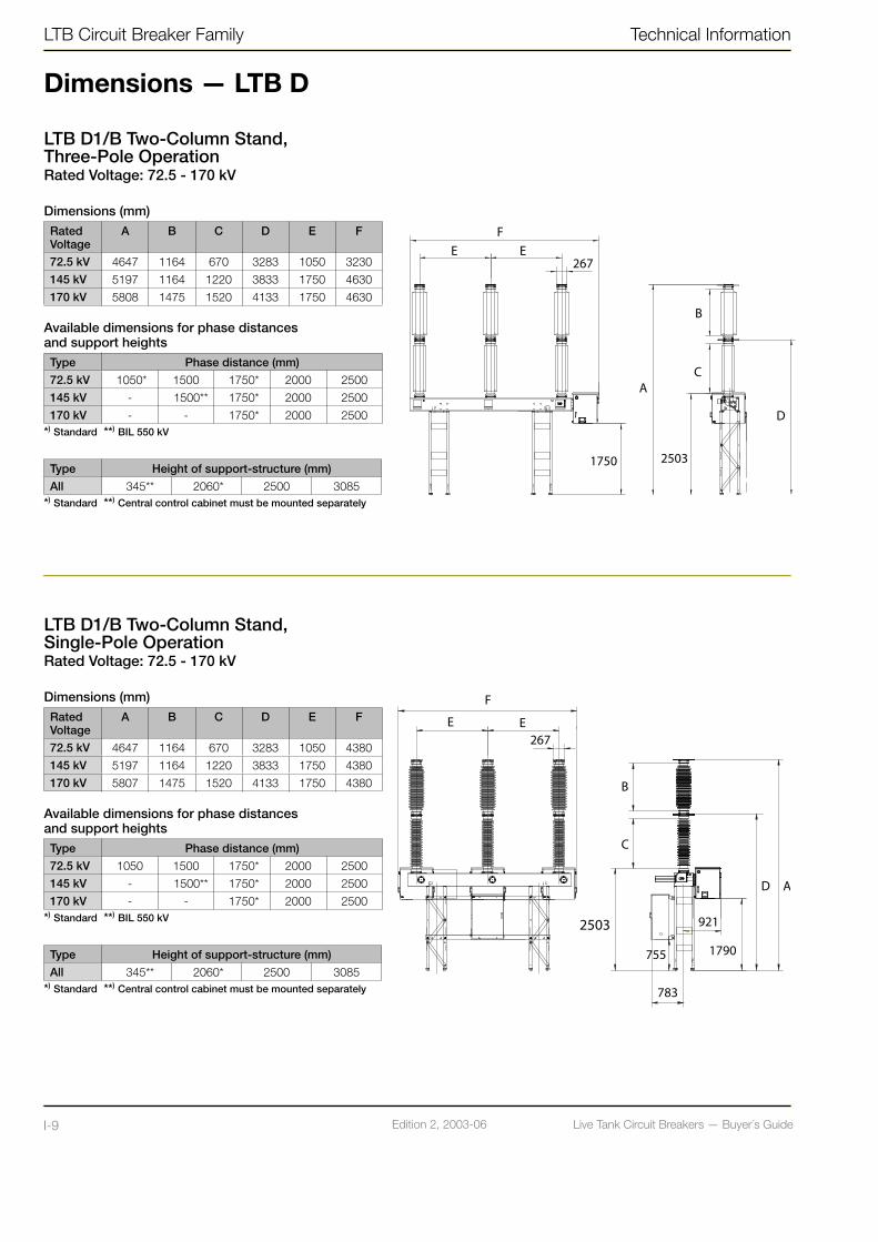
Live Tank Circuit Breakers — Buyer´s GuideI-9 Edition 2, 2003-06 Live Tank Circuit Breakers — Buyer´s Guide I-10Edition 2, 2003-06
LTB Circuit Breaker Family Technical Information
Dimensions — LTB D
LTB D1/B Two-Column Stand, Three-Pole OperationRated Voltage: 72.5 - 170 kV
Dimensions (mm) RatedVoltage
A B C D E F
72.5 kV 4647 1164 670 3283 1050 3230
145 kV 5197 1164 1220 3833 1750 4630
170 kV 5808 1475 1520 4133 1750 4630
Available dimensions for phase distances and support heightsType Phase distance (mm)
72.5 kV 1050* 1500 1750* 2000 2500
145 kV - 1500** 1750* 2000 2500
170 kV - - 1750* 2000 2500*) Standard **) BIL 550 kV
Type Height of support-structure (mm)
All 345** 2060* 2500 3085*) Standard **) Central control cabinet must be mounted separately
LTB D1/B Two-Column Stand,Single-Pole OperationRated Voltage: 72.5 - 170 kV
Dimensions (mm)RatedVoltage
A B C D E F
72.5 kV 4647 1164 670 3283 1050 4380
145 kV 5197 1164 1220 3833 1750 4380
170 kV 5807 1475 1520 4133 1750 4380
Available dimensions for phase distances and support heightsType Phase distance (mm)
72.5 kV 1050 1500 1750* 2000 2500
145 kV - 1500** 1750* 2000 2500
170 kV - - 1750* 2000 2500*) Standard **) BIL 550 kV
Type Height of support-structure (mm)
All 345** 2060* 2500 3085*) Standard **) Central control cabinet must be mounted separately

Live Tank Circuit Breakers — Buyer´s GuideI-9 Edition 2, 2003-06 Live Tank Circuit Breakers — Buyer´s Guide I-10Edition 2, 2003-06
Technical Information LTB Circuit Breaker Family
Dimensions — LTB D
LTB D1/B Three-Column Stand,Three-Pole OperationRated Voltage: 72.5 - 170 kV
Dimensions (mm)RatedVoltage
A B C D E F
72.5 kV 4647 1164 670 3283 1050 3266
145 kV 5197 1164 1220 3833 1750 4666
170 kV 5808 1475 1520 4133 1750 4666
Available dimensions for phase distances and support heightsType Phase distance (mm)
72.5 kV 1050* 1500 1750* 2000 2500 3000
145 kV - 1500 1750* 2000 2500 3000
170 kV - - 1750* 2000 2500 3000*) Standard **) BIL 550 kV
Type Height of support-structure (mm)
All 680** 2160 2383* 2830*) Standard **) Central control cabinet must be mounted separately
LTB D1/B Three-Column Stand,Single-Pole OperationRated Voltage: 72.5 - 170 kV
Dimensions (mm)RatedVoltage
A B C D E F
72.5 kV 4647 1164 670 3283 1750 4380
145 kV 5197 1164 1220 3833 1750 4380
170 kV 5808 1475 1520 4133 1750 4380
Available dimensions for phase distances and support heights Type Phase distance (mm)
72.5 kV 1050 1500 1750* 2000 2500 3000
145 kV - 1500 1750* 2000 2500 3000
170 kV - - 1750* 2000 2500 3000*) Standard **) BIL 550 kV
Type Height of support-structure (mm)
All 680** 2160 2383* 2830*) Standard **) Central control cabinet must be mounted separately
**
**
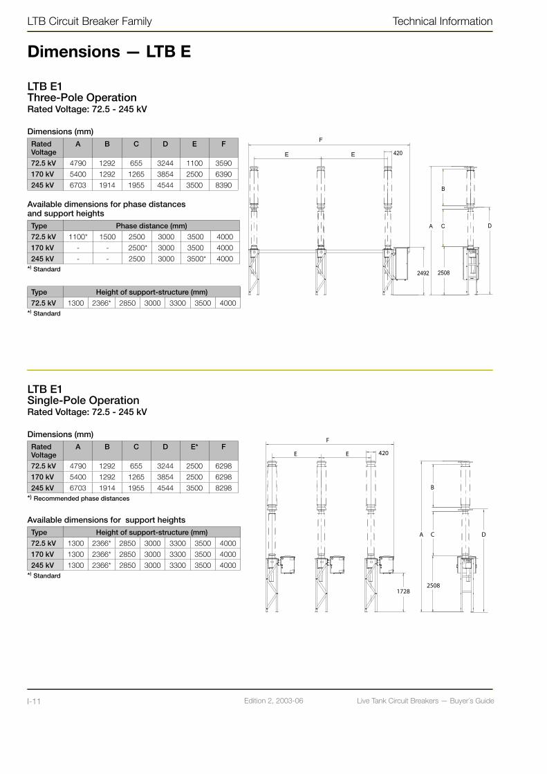
Live Tank Circuit Breakers — Buyer´s GuideI-11 Edition 2, 2003-06 Live Tank Circuit Breakers — Buyer´s Guide I-12Edition 2, 2003-06
LTB Circuit Breaker Family Technical Information
Dimensions — LTB E
LTB E1Three-Pole OperationRated Voltage: 72.5 - 245 kV
Dimensions (mm) RatedVoltage
A B C D E F
72.5 kV 4790 1292 655 3244 1100 3590
170 kV 5400 1292 1265 3854 2500 6390
245 kV 6703 1914 1955 4544 3500 8390
Available dimensions for phase distances and support heightsType Phase distance (mm)
72.5 kV 1100* 1500 2500 3000 3500 4000
170 kV - - 2500* 3000 3500 4000
245 kV - - 2500 3000 3500* 4000*) Standard
Type Height of support-structure (mm)
72.5 kV 1300 2366* 2850 3000 3300 3500 4000*) Standard
LTB E1 Single-Pole OperationRated Voltage: 72.5 - 245 kV
Dimensions (mm) RatedVoltage
A B C D E* F
72.5 kV 4790 1292 655 3244 2500 6298
170 kV 5400 1292 1265 3854 2500 6298
245 kV 6703 1914 1955 4544 3500 8298*) Recommended phase distances
Available dimensions for support heights Type Height of support-structure (mm)
72.5 kV 1300 2366* 2850 3000 3300 3500 4000
170 kV 1300 2366* 2850 3000 3300 3500 4000
245 kV 1300 2366* 2850 3000 3300 3500 4000*) Standard

Live Tank Circuit Breakers — Buyer´s GuideI-11 Edition 2, 2003-06 Live Tank Circuit Breakers — Buyer´s Guide I-12Edition 2, 2003-06
Technical Information LTB Circuit Breaker Family
Dimensions — LTB E
LTB 420E2Single-Pole OperationRated Voltage: 362 - 420 kVAll dimensions in mm
Available dimensions for support heights
Type Height of support-structure
420 kV - 2366* 2850 3000 3300 3500 4000
*) Standard
LTB 550E2Single-Pole OperationRated Voltage: 550 kVAll dimensions in mm
Available dimensions for support heights
Type Height of support-structure
550 kV - 2366* 2850 3000 3300 3500 4000
*) Standard

Live Tank Circuit Breakers — Buyer´s GuideI-13 Edition 2, 2003-06 Live Tank Circuit Breakers — Buyer´s Guide I-14Edition 2, 2003-06
LTB Circuit Breaker Family Technical Information
Shipping Data for Standard LTB D
LTB 72,5D1/B, Three-Pole Operated, Three Column StandEquipment Number of
casesDimensions L x W x H
Gross Weight
m kg
Breaker Poles 1 3.26 x 1.78 x 0.72 1045
Operating mechanism 1 1.18 x 1.05 x 1.00 250
Support Structure 1 2.40 x 0.58 x 0.44 330
Total 3 6.0 m3 1625
LTB 145D1/B, Three-Pole Operated, Three Column StandEquipment Number of
casesDimensions L x W x H
Gross Weight
m kg
Breaker Poles 1 3.26 x 1.78 x 0.72 1155
Operating mechanism 1 1.18 x 1.05 x 1.00 250
Support Structure 1 2.40 x 0.58 x 0.44 330
Total 3 6.0 m3 1735
LTB 170D1/B, Three-Pole Operated, Three Column StandEquipment Number of
casesDimensions L x W x H
Gross Weight
m kg
Breaker Poles 1 3.90 x 1.78 x 0.72 1270
Operating mechanism 1 1.18 x 1.05 x 1.00 250
Support Structure 1 2.40 x 0.58 x 0.44 330
Total 3 6.9 m3 1850
LTB 72,5D1/B, Three-Pole Operated, Pole BeamEquipment Number of
casesDimensions L x W x H
Gross Weight
m kg
Breaker Poles 1 3.26 x 1.78 x 0.72 1045
Operating mechanism 1 1.18 x 1.05 x 1.00 250
Pole Beam 1 2.69 x 0.57 x 1.00 200
Support Structure 1 2.40 x 0.58 x 0.44 330
Total 4 7.6 m3 1720
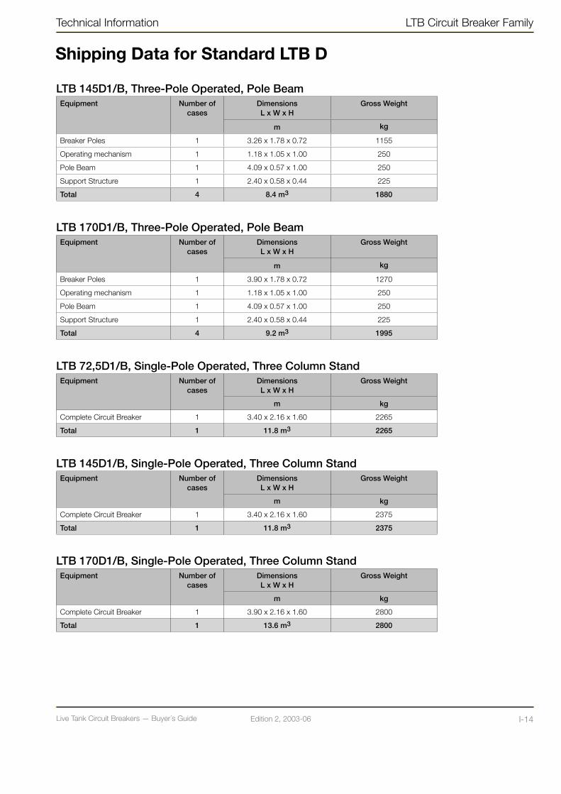
Live Tank Circuit Breakers — Buyer´s GuideI-13 Edition 2, 2003-06 Live Tank Circuit Breakers — Buyer´s Guide I-14Edition 2, 2003-06
Technical Information LTB Circuit Breaker Family
LTB 145D1/B, Three-Pole Operated, Pole BeamEquipment Number of
casesDimensions L x W x H
Gross Weight
m kg
Breaker Poles 1 3.26 x 1.78 x 0.72 1155
Operating mechanism 1 1.18 x 1.05 x 1.00 250
Pole Beam 1 4.09 x 0.57 x 1.00 250
Support Structure 1 2.40 x 0.58 x 0.44 225
Total 4 8.4 m3 1880
LTB 170D1/B, Three-Pole Operated, Pole BeamEquipment Number of
casesDimensions L x W x H
Gross Weight
m kg
Breaker Poles 1 3.90 x 1.78 x 0.72 1270
Operating mechanism 1 1.18 x 1.05 x 1.00 250
Pole Beam 1 4.09 x 0.57 x 1.00 250
Support Structure 1 2.40 x 0.58 x 0.44 225
Total 4 9.2 m3 1995
LTB 72,5D1/B, Single-Pole Operated, Three Column StandEquipment Number of
casesDimensions L x W x H
Gross Weight
m kg
Complete Circuit Breaker 1 3.40 x 2.16 x 1.60 2265
Total 1 11.8 m3 2265
LTB 145D1/B, Single-Pole Operated, Three Column StandEquipment Number of
casesDimensions L x W x H
Gross Weight
m kg
Complete Circuit Breaker 1 3.40 x 2.16 x 1.60 2375
Total 1 11.8 m3 2375
LTB 170D1/B, Single-Pole Operated, Three Column StandEquipment Number of
casesDimensions L x W x H
Gross Weight
m kg
Complete Circuit Breaker 1 3.90 x 2.16 x 1.60 2800
Total 1 13.6 m3 2800
Shipping Data for Standard LTB D
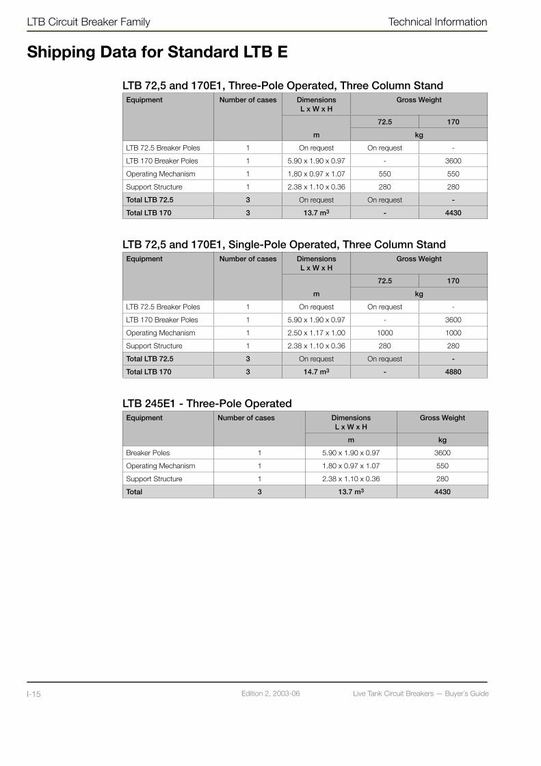
Live Tank Circuit Breakers — Buyer´s GuideI-15 Edition 2, 2003-06 Live Tank Circuit Breakers — Buyer´s Guide I-16Edition 2, 2003-06
LTB Circuit Breaker Family Technical Information
Shipping Data for Standard LTB E
LTB 72,5 and 170E1, Three-Pole Operated, Three Column StandEquipment Number of cases Dimensions
L x W x HGross Weight
m
72.5 170
kg
LTB 72.5 Breaker Poles 1 On request On request -
LTB 170 Breaker Poles 1 5.90 x 1.90 x 0.97 - 3600
Operating Mechanism 1 1,80 x 0.97 x 1.07 550 550
Support Structure 1 2.38 x 1.10 x 0.36 280 280
Total LTB 72.5 3 On request On request -
Total LTB 170 3 13.7 m3 - 4430
LTB 72,5 and 170E1, Single-Pole Operated, Three Column StandEquipment Number of cases Dimensions
L x W x HGross Weight
m
72.5 170
kg
LTB 72.5 Breaker Poles 1 On request On request -
LTB 170 Breaker Poles 1 5.90 x 1.90 x 0.97 - 3600
Operating Mechanism 1 2.50 x 1.17 x 1.00 1000 1000
Support Structure 1 2.38 x 1.10 x 0.36 280 280
Total LTB 72.5 3 On request On request -
Total LTB 170 3 14.7 m3 - 4880
LTB 245E1 - Three-Pole OperatedEquipment Number of cases Dimensions
L x W x HGross Weight
m kg
Breaker Poles 1 5.90 x 1.90 x 0.97 3600
Operating Mechanism 1 1.80 x 0.97 x 1.07 550
Support Structure 1 2.38 x 1.10 x 0.36 280
Total 3 13.7 m3 4430

Live Tank Circuit Breakers — Buyer´s GuideI-15 Edition 2, 2003-06 Live Tank Circuit Breakers — Buyer´s Guide I-16Edition 2, 2003-06
Technical Information LTB Circuit Breaker Family
LTB 245E1 - Single-Pole OperatedEquipment Number of cases Dimensions
L x W x HGross Weight
m kg
Breaker Poles 1 5.90 x 1.90 x 0.97 3600
Operating Mechanism 1 2.50 x 1.17 x 1.00 1000
Support Structure 1 2.38 x 1.10 x 0.36 280
Total 3 14.7 m3 4880
LTB 420E2 - Single-Pole Operated 25 mm/kVEquipment Number of cases Dimensions
L x W x HGross Weight
m kg
Breaker Units 1 5.12 x 1.96 x 1.20 3600
Support Column 1 5.10 x 1.90 x 0.90 2400
Operating Mechanism 3 (3) x 1.80 x 0.97 x 1.07 (3) x 550
Support Structure 1 2.40 x 1.10 x 0.40 440
(Capacitors) if included (1) (2.33 x 1.21 x 1.03) (1060)
Total 6 (7) 27.4 (30.3) m3 8090 (9150)
LTB 420E2 - Single-Pole Operated 31 mm/kVEquipment Number of cases Dimensions
L x W x HGross Weight
m kg
Breaker Units 1 5.12 x 1.96 x 1.20 3600
Support Column 1 6.10 x 1.90 x 0.90 2800
Operating Mechanism 3 (3) x 1.80 x 0.97 x 1.07 (3) x 550
Support Structure 1 2.40 x 1.10 x 0.40 440
(Capacitors) if included (1) (2.33 x 1.21 x 1.03) (1060)
Total 6 (7) 29.1 (32.0) m3 8490 (9550)
LTB 550E2 - Single-Pole Operated 25 mm/kVEquipment Number of cases Dimensions
L x W x HGross Weight
m kg
Breaker Units 1 5.12 x 1.96 x 1.20 3600
Support Column 1 6.10 x 1.90 x 0.90 2800
Operating Mechanism 3 (3) x 1.80 x 0.97 x 1.07 (3) x 550
Support Structure 1 2.40 x 1.10 x 0.40 440
Capacitors 1 (2.33 x 1.21 x 1.03) 1060
Total 7 32.0 m3 9550
Shipping Data for Standard LTB E
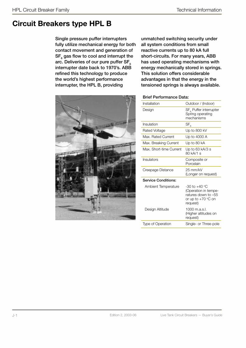
Live Tank Circuit Breakers — Buyer´s GuideJ-1 Edition 2, 2003-06 Live Tank Circuit Breakers — Buyer´s Guide J-2Edition 2, 2003-06
HPL Circuit Breaker Family Technical Information
Circuit Breakers type HPL B
Single pressure puffer interrupters fully utilize mechanical energy for both contact movement and generation of SF6 gas flow to cool and interrupt the arc. Deliveries of our pure puffer SF6 interrupter date back to 1970’s. ABB refined this technology to produce the world’s highest performance interrupter, the HPL B, providing
unmatched switching security under all system conditions from small reactive currents up to 80 kA full short-circuits. For many years, ABB has used operating mechanisms with energy mechanically stored in springs. This solution offers considerable advantages in that the energy in the tensioned springs is always available.
Brief Performance Data:
Installation Outdoor / (Indoor)
Design SF6 Puffer interrupter Spring operating mechanisms
Insulation SF6
Rated Voltage Up to 800 kV
Max. Rated Current Up to 4000 A
Max. Breaking Current Up to 80 kA
Max. Short-time Current Up to 63 kA/3 s80 kA/1 s
Insulators Composite or Porcelain
Creepage Distance 25 mm/kV (Longer on request)
Service Conditions:
Ambient Temperature -30 to +40 oC(Operation in tempe-ratures down to –55 or up to +70 oC on request)
Design Altitude 1000 m.a.s.l.(Higher altitudes on request)
Type of Operation Single- or Three-pole

Live Tank Circuit Breakers — Buyer´s GuideJ-1 Edition 2, 2003-06 Live Tank Circuit Breakers — Buyer´s Guide J-2Edition 2, 2003-06
Technical Information HPL Circuit Breaker Family
Circuit Breakers type HPL B
MaterialThe selected components of aluminum (mechanism housings, HV-terminals, cubicles) give a high degree of resistance to corrosion, without the need of extra protection. For use in extreme trying environments HPL can be delivered with a protective painting.
The support structure and protective tubes for the pull rods are made of hot-dipped galvanized steel.
InsulatorsHPL circuit breaker is as standard delivered with insulators that consist of high-grade brown-glazed porcelain or composite insulators (light gray). HPL with light gray porcelain can be delivered on request.
HPL is available as standard with long or extra long creepage distances.
Longer creepage distances can be quoted on request.
More information about our composite insulators can be found in chapter N-1.
Mechanical StrengthThe mechanical durability gives a sufficient safety margin for normal wind loads and static and dynamic forces from conductors.
Seismic Withstand StrengthAll HPL circuit breakers can in their standard versions, withstand seismic accelerations up to 3 m/s2 (0,3 g) in accordance with IEC 1166 and IEEE 693.
For higher acceleration see chapter Q-1 “Seismic Withstand Capability”.
Rating PlatesA rating plate, which includes data for the circuit breaker, is placed on the side of the operating mechanism cubicle. The rating plate is made of stainless steel with engraved text.
Operating MechanismThe circuit breaker is operated by motor charged spring operating mechanism(s), type BLG, which is installed in a compact splash proof and corrosion resistant housing, attached to the structure. • One operating mechanism is used for
three-pole operation for HPL 72.5 - 300 kV.
• Three operating mechanisms are used for single-pole operation for HPL 72.5 - 550 kV.
• Six operating mechanisms (two per pole) for single-pole operation for HPL 800 kV.
More detailed information about the ope-rating mechanism type BLG can be found in chapters G-1 and L-1 in this Buyer’s Guide.
Sealing Systems for SF6 Volume The sealing system consists of double nitrile rubber O-rings in all static seals and double X-rings in all dynamic seals.
This type of sealings has been used in our circuit breakers for more than 30 years with excellent service record at varying climatic conditions.
The SF6-gas leakage is less than 1% per year.
SF6 Density MonitoringSince the interrupting capability is dependent on the density of the SF6 gas, the HPL circuit breaker is provided with density monitor(s). The density monitor consists of a temperature compensated pressure switch. Therefore, alarm signal and blocking function are activated only if the pressure drops due to leakage.
All HPL circuit breakers have one density monitor per pole.
More information can be found in chapter B-1 “Explanations”
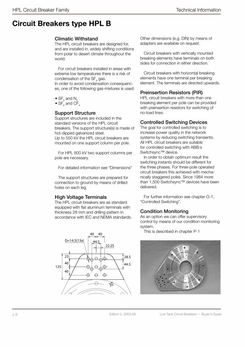
Live Tank Circuit Breakers — Buyer´s GuideJ-3 Edition 2, 2003-06 Live Tank Circuit Breakers — Buyer´s Guide J-4Edition 2, 2003-06
HPL Circuit Breaker Family Technical Information
Climatic WithstandThe HPL circuit breakers are designed for, and are installed in, widely shifting conditions from polar to desert climate throughout the world.
For circuit breakers installed in areas with extreme low temperatures there is a risk of condensation of the SF6 gas. In order to avoid condensation consequenc-es, one of the following gas-mixtures is used:
• SF6 and N2 • SF6 and CF4
Support Structure Support structures are included in the standard versions of the HPL circuit breakers. The support structure(s) is made of hot-dipped galvanized steel. Up to 550 kV the HPL circuit breakers are mounted on one support column per pole.
For HPL 800 kV two support columns per pole are necessary.
For detailed information see “Dimensions”
The support structures are prepared for connection to ground by means of drilled holes on each leg.
High Voltage TerminalsThe HPL circuit breakers are as standard equipped with flat aluminum terminals with thickness 28 mm and drilling pattern in accordance with IEC and NEMA standards.
Other dimensions (e.g. DIN) by means of adapters are available on request.
Circuit breakers with vertically mounted breaking elements have terminals on both sides for connection in either direction.
Circuit breakers with horizontal breaking elements have one terminal per breaking element. The terminals are directed upwards.
Preinsertion Resistors (PIR)HPL circuit breakers with more than one breaking element per pole can be provided with preinsertion resistors for switching of no-load lines.
Controlled Switching DevicesThe goal for controlled switching is to increase power quality in the network systems by reducing switching transients. All HPL circuit breakers are suitable for controlled switching with ABB:s Switchsync™ device.
In order to obtain optimum result the switching instants should be different for the three phases. For three-pole operated circuit breakers this achieved with mecha-nically staggered poles. Since 1984 more than 1,500 Switchsync™ devices have been delivered.
For further information see chapter O-1, “Controlled Switching”.
Condition MonitoringAs an option we can offer supervisory control by means of our condition monitoring system.
This is described in chapter P-1
Circuit Breakers type HPL B
Live Tank Circuit Breakers — Buyer´s GuideJ-3 Edition 2, 2003-06 Live Tank Circuit Breakers — Buyer´s Guide J-4Edition 2, 2003-06
Technical Information HPL Circuit Breaker Family
Circuit Breakers type HPL B
Type TestsThe HPL circuit breakers have been type tested in accordance with IEC and/or ANSI standards. Type test reports can be presented on request.
Routine TestsAll HPL circuit breakers are routine tested before delivery. Our test program complies with IEC and ANSI standards.
For detailed information please see spe-cial chapter R-1 regarding “Quality Control and Testing”.
TransportThe HPL circuit breakers are normally packed and transported in seaworthy wooden crates.
The circuit breaker poles with one brea-king element per pole are transported as complete units.
For circuit breakers with two or more breaking elements per pole, the number of cases depends on the circuit breaker type.
For detailed information regarding weights and dimensions see “Shipping data”.
Breaking elements as well as support insulators are filled with gas at a slight overpressure.
Arrival InspectionOn arrival the packaging and contents should be checked against packing list. In the event of damage to the goods, contact ABB for advice, before further handling of the goods takes place. Any damage ought to be documented (photographed).
Erection and CommissioningAssembly instructions are provided with each delivery.
Erection work at site can be done in 1-7 days depending on HPL type and size.
Filling of SF6-gas to specified rated pres-sure is done by using the following pressuri-zing equipment, which can be delivered on request:• One special control valve, for connection to
the gas bottle, and a 20 m gas-filled hose with connectors.
• A complementary control valve for connection to CF4 or N2 gas bottle (for mixed gas filling).
When using the above gas equipment, filling can be done without gas being released into the atmosphere.
For illustration of gas filling equipment see page I-6.
MaintenanceHPL is designed for a service life of more than 30 years or 10,000 mechanical (no load) operations. For current switching the number of operations before service is dependent on the interrupted current.
Inspection, maintenance and overhaul should be carried out at regular intervals de-pending on the ambient conditions and the number of operations.
The general actions are described below:
• 1-2 years: Ocular inspection
• 7-10 years or 2,000 mechanical operations: Extended ocular inspection and some lubrication of the operating mechanism(s)
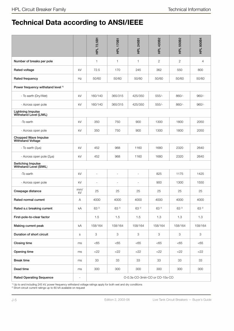
Live Tank Circuit Breakers — Buyer´s GuideJ-5 Edition 2, 2003-06 Live Tank Circuit Breakers — Buyer´s Guide J-6Edition 2, 2003-06
HPL Circuit Breaker Family Technical Information
Technical Data according to ANSI/IEEE
HP
L 72
.5B
1
HP
L 17
0B1
HP
L 24
5B1
HP
L 42
0B2
HP
L 55
0B2
HP
L 80
0B4
Number of breaks per pole 1 1 1 2 2 4
Rated voltage kV 72.5 170 245 362 550 800
Rated frequency Hz 50/60 50/60 50/60 50/60 50/60 50/60
Power frequency withstand level 1)
- To earth (Dry/Wet) kV 160/140 365/315 425/350 555/- 860/- 960/-
- Across open pole kV 160/140 365/315 425/350 555/- 860/- 960/-
Lightning Impulse Withstand Level (LIWL)
-To earth kV 350 750 900 1300 1800 2050
- Across open pole kV 350 750 900 1300 1800 2050
Chopped Wave Impulse Withstand Voltage
- To earth (2µs) kV 452 968 1160 1680 2320 2640
- Across open pole (2µs) kV 452 968 1160 1680 2320 2640
Switching Impulse Withstand Level (SIWL)
-To earth kV - - - 825 1175 1425
- Across open pole kV - - - 900 1300 1550
Creepage distance mm/kV 25 25 25 25 25 25
Rated normal current A 4000 4000 4000 4000 4000 4000
Rated s.c breaking current kA 63 2) 63 2) 63 2) 63 2) 63 2) 63 2)
First-pole-to-clear factor 1.5 1.5 1.5 1.3 1.3 1.3
Making current peak kA 158/164 158/164 158/164 158/164 158/164 158/164
Duration of short circuit s 3 3 3 3 3 3
Closing time ms <65 <65 <65 <65 <65 <65
Opening time ms <22 <22 <22 <22 <22 <22
Break time ms 33 33 33 33 33 33
Dead time ms 300 300 300 300 300 300
Rated Operating Sequence - O-0.3s-CO-3min-CO or CO-15s-CO
1) Up to and including 245 kV, power frequency withstand voltage ratings apply for both wet and dry conditions2) Short-circuit current ratings up to 80 kA available on request
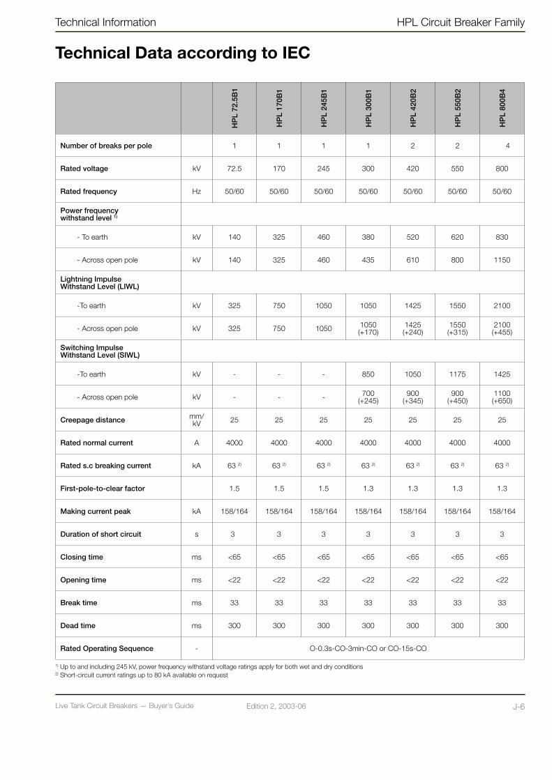
Live Tank Circuit Breakers — Buyer´s GuideJ-5 Edition 2, 2003-06 Live Tank Circuit Breakers — Buyer´s Guide J-6Edition 2, 2003-06
Technical Information HPL Circuit Breaker Family
Technical Data according to IEC
HP
L 72
.5B
1
HP
L 17
0B1
HP
L 24
5B1
HP
L 30
0B1
HP
L 42
0B2
HP
L 55
0B2
HP
L 80
0B4
Number of breaks per pole 1 1 1 1 2 2 4
Rated voltage kV 72.5 170 245 300 420 550 800
Rated frequency Hz 50/60 50/60 50/60 50/60 50/60 50/60 50/60
Power frequency withstand level 1)
- To earth kV 140 325 460 380 520 620 830
- Across open pole kV 140 325 460 435 610 800 1150
Lightning Impulse Withstand Level (LIWL)
-To earth kV 325 750 1050 1050 1425 1550 2100
- Across open pole kV 325 750 1050 1050 (+170)
1425 (+240)
1550 (+315)
2100 (+455)
Switching Impulse Withstand Level (SIWL)
-To earth kV - - - 850 1050 1175 1425
- Across open pole kV - - - 700 (+245)
900 (+345)
900 (+450)
1100 (+650)
Creepage distance mm/kV 25 25 25 25 25 25 25
Rated normal current A 4000 4000 4000 4000 4000 4000 4000
Rated s.c breaking current kA 63 2) 63 2) 63 2) 63 2) 63 2) 63 2) 63 2)
First-pole-to-clear factor 1.5 1.5 1.5 1.3 1.3 1.3 1.3
Making current peak kA 158/164 158/164 158/164 158/164 158/164 158/164 158/164
Duration of short circuit s 3 3 3 3 3 3 3
Closing time ms <65 <65 <65 <65 <65 <65 <65
Opening time ms <22 <22 <22 <22 <22 <22 <22
Break time ms 33 33 33 33 33 33 33
Dead time ms 300 300 300 300 300 300 300
Rated Operating Sequence - O-0.3s-CO-3min-CO or CO-15s-CO
1) Up to and including 245 kV, power frequency withstand voltage ratings apply for both wet and dry conditions2) Short-circuit current ratings up to 80 kA available on request

Live Tank Circuit Breakers — Buyer´s GuideJ-7 Edition 2, 2003-06 Live Tank Circuit Breakers — Buyer´s Guide J-8Edition 2, 2003-06
HPL Circuit Breaker Family Technical Information
Dimensions — HPL B
HPL B1 Three-Pole OperationRated Voltage: 72.5 - 300 kV
Dimensions (mm) RatedVoltage
A B C D E F
72.5 kV 5213 1724 655 3244 1100 3600
170 kV 6063 1724 1505 4094 2500 6400
245 kV 6703 1914 1955 4544 3500 8400
300 kV 7163 2124 2205 4794 3500 8400
Available dimensions for phase distances and support heights Type Phase distance (mm)
72.5 kV 1100* 1500 2500 3000 3500 4000
170 kV - - 2500* 3000 3500 4000
245 kV - - 2500 3000 3500* 4000
300 kV - - - 3000 3500* 4000*) Standard
Type Height of support-structure (mm)
All 1300 2366* 2850 3000 3300 3500 4000*) Standard
HPL B1 Single-Pole OperationRated Voltage: 72.5 - 300 kV
Dimensions (mm) RatedVoltage
A B C D E* F
72.5 kV 5213 1724 655 3244 2500 6400
170 kV 6063 1724 1505 4094 2500 6400
245 kV 6703 1914 1955 4544 3500 8400
300 kV 7163 2124 2205 4794 3500 8400*) Recommended phase distances
Available dimensions for support heights
Type Height of support-structure (mm)
All 1300 2366* 2850 3000 3300 3500 4000*) Standard
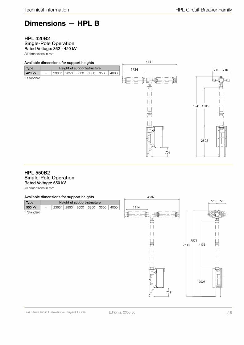
Live Tank Circuit Breakers — Buyer´s GuideJ-7 Edition 2, 2003-06 Live Tank Circuit Breakers — Buyer´s Guide J-8Edition 2, 2003-06
Technical Information HPL Circuit Breaker Family
Dimensions — HPL B
HPL 550B2Single-Pole OperationRated Voltage: 550 kVAll dimensions in mm
Available dimensions for support heights
Type Height of support-structure
550 kV - 2366* 2850 3000 3300 3500 4000
*) Standard
HPL 420B2Single-Pole OperationRated Voltage: 362 - 420 kVAll dimensions in mm
Available dimensions for support heightsType Height of support-structure
420 kV - 2366* 2850 3000 3300 3500 4000
*) Standard
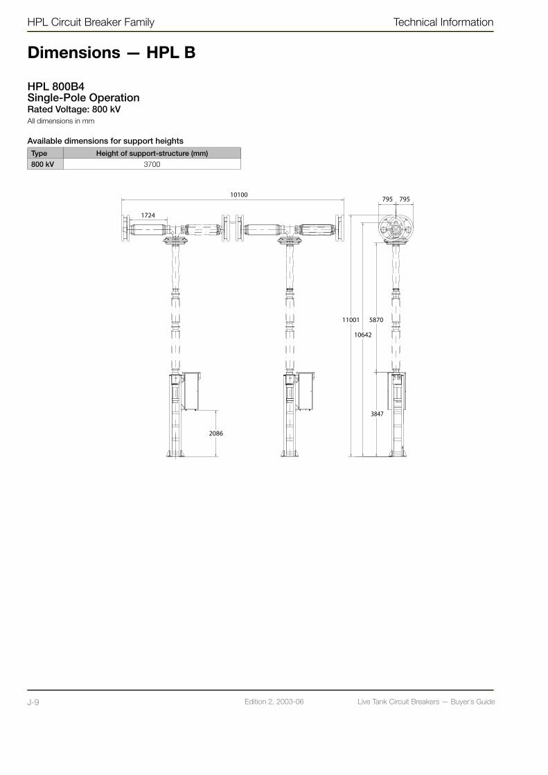
Live Tank Circuit Breakers — Buyer´s GuideJ-9 Edition 2, 2003-06 Live Tank Circuit Breakers — Buyer´s Guide J-10Edition 2, 2003-06
HPL Circuit Breaker Family Technical Information
Dimensions — HPL B
HPL 800B4Single-Pole OperationRated Voltage: 800 kVAll dimensions in mm
Available dimensions for support heights
Type Height of support-structure (mm)
800 kV 3700

Live Tank Circuit Breakers — Buyer´s GuideJ-9 Edition 2, 2003-06 Live Tank Circuit Breakers — Buyer´s Guide J-10Edition 2, 2003-06
Technical Information HPL Circuit Breaker Family
Shipping Data for Standard HPL B
HPL 72,5B1, Three-Pole Operated and Single-pole OperatedEquipment Number of cases Dimensions
L x W x HGross Weight
m kg
Breaker Poles 1 4.37 x 1.91 x 0.98 2800
Operating MechanismThree-pole operated
1 1.80 x 0.97 x 1.07 550
Operating MechanismSingle-pole operated
3 (3) x 1.80 x 0.97 x 1.07 (3) x 550
Support Structure 1 2.38 x 1.10 x 0.36 280
TotalThree-pole operated
3 11.0 m3 3630
TotalSingle-pole operated
5 14.7 m3 4730
HPL 170B1, Three-Pole Operated and Single-pole OperatedEquipment Number of cases Dimensions
L x W x HGross Weight
m kg
Breaker Poles 1 5.21 x 1.90 x 0.90 3250
Operating MechanismThree-pole operated
1 1.80 x 0.97 x 1.07 550
Operating MechanismSingle-pole operated
3 (3) x 1.80 x 0.97 x 1.07 (3) x 550
Support Structure 1 2.38 x 1.10 x 0.36 280
TotalThree-pole operated
3 11.7 m3 4080
TotalSingle-pole operated
5 15.5 m3 5180
HPL 245B1, Three-Pole Operated and Single-pole OperatedEquipment Number of cases Dimensions
L x W x HGross Weight
m kg
Breaker Poles 1 5.90 x 1.90 x 0.97 3600
Operating MechanismThree-pole operated
1 1.80 x 0.97 x 1.07 550
Operating MechanismSingle-pole operated
3 (3) x 1.80 x 0.97 x 1.07 (3) x 550
Support Structure 1 2.38 x 1.10 x 0.36 280
TotalThree-pole operated
3 13.7 m3 4430
TotalSingle-pole operated
5 17.4 m3 5530
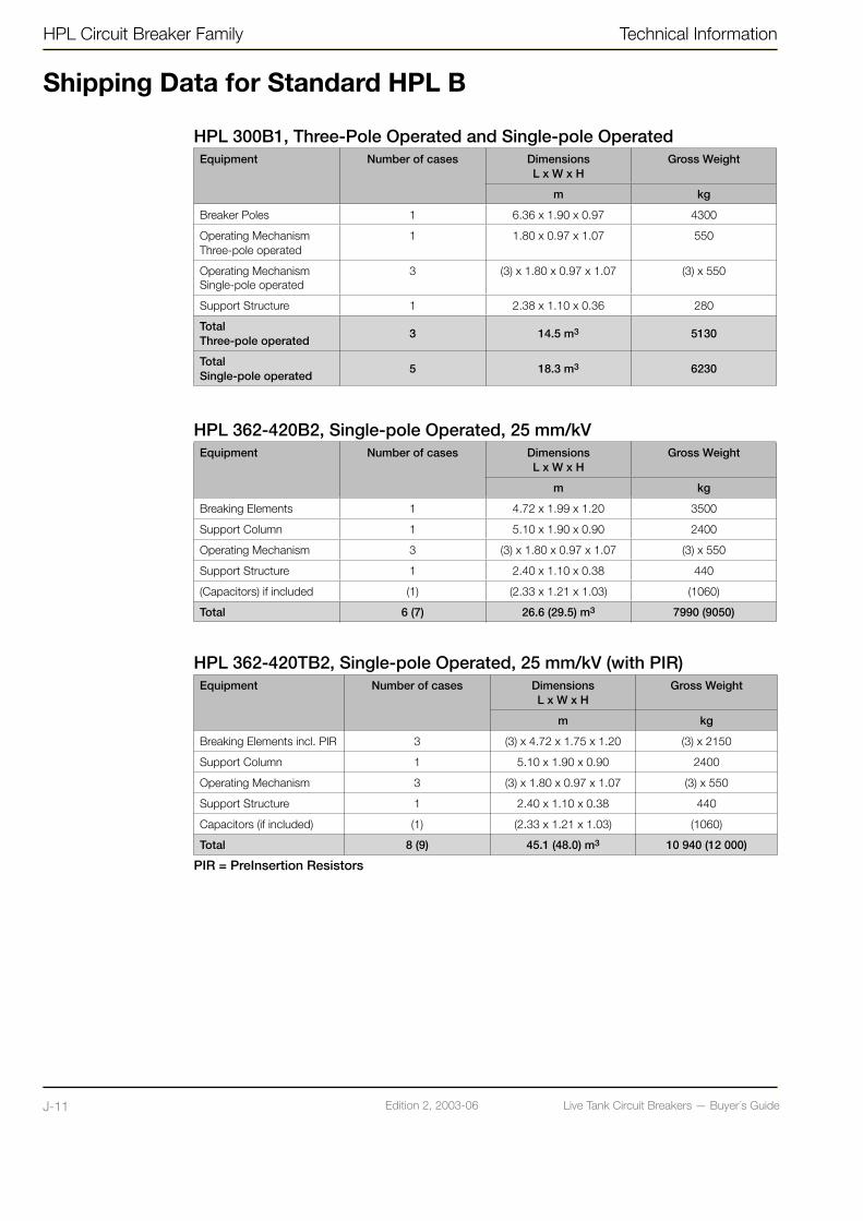
Live Tank Circuit Breakers — Buyer´s GuideJ-11 Edition 2, 2003-06 Live Tank Circuit Breakers — Buyer´s Guide J-12Edition 2, 2003-06
HPL Circuit Breaker Family Technical Information
HPL 300B1, Three-Pole Operated and Single-pole OperatedEquipment Number of cases Dimensions
L x W x HGross Weight
m kg
Breaker Poles 1 6.36 x 1.90 x 0.97 4300
Operating MechanismThree-pole operated
1 1.80 x 0.97 x 1.07 550
Operating MechanismSingle-pole operated
3 (3) x 1.80 x 0.97 x 1.07 (3) x 550
Support Structure 1 2.38 x 1.10 x 0.36 280
TotalThree-pole operated
3 14.5 m3 5130
TotalSingle-pole operated
5 18.3 m3 6230
HPL 362-420B2, Single-pole Operated, 25 mm/kVEquipment Number of cases Dimensions
L x W x HGross Weight
m kg
Breaking Elements 1 4.72 x 1.99 x 1.20 3500
Support Column 1 5.10 x 1.90 x 0.90 2400
Operating Mechanism 3 (3) x 1.80 x 0.97 x 1.07 (3) x 550
Support Structure 1 2.40 x 1.10 x 0.38 440
(Capacitors) if included (1) (2.33 x 1.21 x 1.03) (1060)
Total 6 (7) 26.6 (29.5) m3 7990 (9050)
HPL 362-420TB2, Single-pole Operated, 25 mm/kV (with PIR)Equipment Number of cases Dimensions
L x W x HGross Weight
m kg
Breaking Elements incl. PIR 3 (3) x 4.72 x 1.75 x 1.20 (3) x 2150
Support Column 1 5.10 x 1.90 x 0.90 2400
Operating Mechanism 3 (3) x 1.80 x 0.97 x 1.07 (3) x 550
Support Structure 1 2.40 x 1.10 x 0.38 440
Capacitors (if included) (1) (2.33 x 1.21 x 1.03) (1060)
Total 8 (9) 45.1 (48.0) m3 10 940 (12 000)
PIR = PreInsertion Resistors
Shipping Data for Standard HPL B

Live Tank Circuit Breakers — Buyer´s GuideJ-11 Edition 2, 2003-06 Live Tank Circuit Breakers — Buyer´s Guide J-12Edition 2, 2003-06
Technical Information HPL Circuit Breaker Family
HPL 362-420B2, Single-pole Operated, 31 mm/kV (without PIR)Equipment Number of cases Dimensions
L x W x HGross Weight
m kg
Breaking Elements 1 4.72 x 1.99 x 1.20 3500
Support Column 1 6.10 x 1.90 x 0.90 2800
Operating Mechanism 3 (3) x 1.80 x 0.97 x 1.07 (3) x 550
Support Structure 1 2.40 x 1.10 x 0.38 440
(Capacitors) if included (1) (2.33 x 1.21 x 1.03) (1060)
Total 6 (7) 28.3 (31.2) m3 8390 (9450)
HPL 362-420TB2, Single-pole Operated, 31 mm/kV (with PIR)Equipment Number of cases Dimensions
L x W x HGross Weight
m kg
Breaking Elements incl. PIR 3 (3) x 5.30 x 1.80 x 1.10 (3) x 2600
Support Column 1 6.10 x 1.90 x 0.90 2800
Operating Mechanism 3 (3) x 1.80 x 0.97 x 1.07 (3) x 550
Support Structure 1 2.40 x 1.10 x 0.38 440
Capacitors (if included) (1) (2.33 x 1.21 x 1.03) (1060)
Total 8 (9) 48.5 (51.4) m3 12 690 (13 750)
HPL 550B2, Single-pole Operated, (without PIR)Equipment Number of cases Dimensions
L x W x HGross Weight
m kg
Breaking Elements 1 5.12 x 1.96 x 1.20 3600
Support Column 1 6.10 x 1.90 x 0.90 2800
Operating Mechanism 3 (3) x 1.80 x 0.97 x 1.07 (3) x 550
Support Structure 1 2.40 x 1.10 x 0.38 440
Capacitors 1 (2.33 x 1.21 x 1.03) 1060
Total 7 32.0 m3 9550
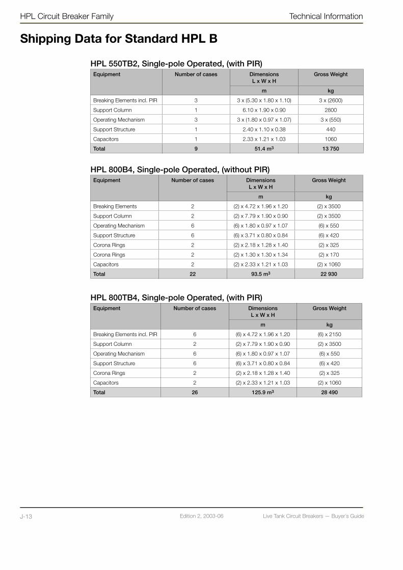
Live Tank Circuit Breakers — Buyer´s GuideJ-13 Edition 2, 2003-06 Live Tank Circuit Breakers — Buyer´s Guide K-1Edition 2, 2003-06
HPL Circuit Breaker Family Technical Information
Shipping Data for Standard HPL B
HPL 550TB2, Single-pole Operated, (with PIR)Equipment Number of cases Dimensions
L x W x HGross Weight
m kg
Breaking Elements incl. PIR 3 3 x (5.30 x 1.80 x 1.10) 3 x (2600)
Support Column 1 6.10 x 1.90 x 0.90 2800
Operating Mechanism 3 3 x (1.80 x 0.97 x 1.07) 3 x (550)
Support Structure 1 2.40 x 1.10 x 0.38 440
Capacitors 1 2.33 x 1.21 x 1.03 1060
Total 9 51.4 m3 13 750
HPL 800B4, Single-pole Operated, (without PIR)Equipment Number of cases Dimensions
L x W x HGross Weight
m kg
Breaking Elements 2 (2) x 4.72 x 1.96 x 1.20 (2) x 3500
Support Column 2 (2) x 7.79 x 1.90 x 0.90 (2) x 3500
Operating Mechanism 6 (6) x 1.80 x 0.97 x 1.07 (6) x 550
Support Structure 6 (6) x 3.71 x 0.80 x 0.84 (6) x 420
Corona Rings 2 (2) x 2.18 x 1.28 x 1.40 (2) x 325
Corona Rings 2 (2) x 1.30 x 1.30 x 1.34 (2) x 170
Capacitors 2 (2) x 2.33 x 1.21 x 1.03 (2) x 1060
Total 22 93.5 m3 22 930
HPL 800TB4, Single-pole Operated, (with PIR)Equipment Number of cases Dimensions
L x W x HGross Weight
m kg
Breaking Elements incl. PIR 6 (6) x 4.72 x 1.96 x 1.20 (6) x 2150
Support Column 2 (2) x 7.79 x 1.90 x 0.90 (2) x 3500
Operating Mechanism 6 (6) x 1.80 x 0.97 x 1.07 (6) x 550
Support Structure 6 (6) x 3.71 x 0.80 x 0.84 (6) x 420
Corona Rings 2 (2) x 2.18 x 1.28 x 1.40 (2) x 325
Capacitors 2 (2) x 2.33 x 1.21 x 1.03 (2) x 1060
Total 26 125.9 m3 28 490

Live Tank Circuit Breakers — Buyer´s GuideJ-13 Edition 2, 2003-06 Live Tank Circuit Breakers — Buyer´s Guide K-1Edition 2, 2003-06
Technical Information BLK Operating Mechanism
Spring Operating Mechanism type BLK
BLK is characterized by a well-proven technology (more than 16,000 units are in service). This proven technology is efficiently combined with modern manufacturing methods and a low number of mechanical components.
This ensures a high degree of total
reliability for the circuit breaker and a minimal need of maintenance. Mechanical life tests have been performed with 10,000 operations.
BLK is designed for widely shifting conditions, from polar to desert climate.
Brief performance dataInstallation Outdoor
Design Spring operated
For circuit breaker LTB D1LTB E1 (Single-poleoperated)
Service conditions: Ambient temperature -50 ˚C to +40 ˚C
(Other on request)

Live Tank Circuit Breakers — Buyer´s GuideK-2 Edition 2, 2003-06 Live Tank Circuit Breakers — Buyer´s Guide K-3Edition 2, 2003-06
MaterialThe housing is made of corrosion resistant, painted aluminum.
Front and back doors are equipped with doorstops and pad lock provisions on door handles.
The doors and walls are insulated for low heat energy consumption and low noise level.
Rating PlatesA rating plate, which includes data for the circuit breaker, is placed on the front door. The rating plate is made of stainless steel with engraved text.
Instructions With each delivery of circuit breakers, there is an extensive product manual that will guide the user how to assemble and handle the apparatus during its lifetime.
Instructions, product manual, circuit diagram and other documents are placed in a compartment inside the front door of the operating mechanism.
Transport BLK for three-pole operation is normally packed and transported in a separate seaworthy wooden crate.
For single-pole operation the three BLK mechanisms are placed in the same crate as the circuit breaker.
Arrival Inspection - UnpackingPlease check the contents and packaging with regard to transport damage immediately on arrival. In the event of any material missing or damage to the goods, contact ABB for advice, before further handling of the goods takes place. Any damage should be documented (photographed).
The operating mechanism must be lifted using the lifting eyes on top of the cabinet. Slings must not be placed around the cabi-net when lifting.
All packing material can be recycled.
StorageThe operating mechanism shall preferably be stored indoors in a dry building. When stored outdoors the internal heater should be used to prevent condensation.
If it is planned to store the unit, an exter-nal connection to the internal heater can be provided on request.
ToolsSpecial tools for assembling and service are placed on the backside of the rear door.
MaintenanceThe maintenance requirements are small, as BLK is designed for a service life of more than 30 years.
Normally it is sufficient with ocular inspection every 1-2 years and some lubrication after 7-10 years or 2,000 close-open operations.
A more detailed check is recommended af-ter 30 years of service or 10,000 operations.
Overhaul and repair work must be performed by authorized personnel only.
The instructions in the manual for operation and maintenance should be observed. This ensures a continued problem-free operation.
DisposalThe disposal should be carried out in accordance with local legal provisions.
The operating mechanism is easy to dis-mantle and the metal parts can be recycled.
BLK Operating Mechanism Technical Information
Spring Operating Mechanism type BLK
Live Tank Circuit Breakers — Buyer´s GuideK-2 Edition 2, 2003-06 Live Tank Circuit Breakers — Buyer´s Guide K-3Edition 2, 2003-06
Technical Information BLK Operating Mechanism
Electrical functions
The principle function of the mechanism’s electrical components is shown in the elementary diagram on next page.
Closing CircuitThe closing coil (Y3) can be activated electrically by means of local or remote control. When the circuit breaker is in closed position, the closing circuit is interrupted by the auxiliary contact (BG).
Tripping CircuitsThe mechanism is provided with two independent trip coils (Y1 and Y2). The mechanism can be operated electrically through local or remote control. With the circuit breaker in the open position, the tripping circuits are interrupted by the auxiliary contact (BG).
InterlocksThe contact on the density switch (BD) actuates the auxiliary relays (K9, K10,), which block the operating impulse if the density of the SF6 gas is too low. The antipumping relay (K3) blocks any remaining closing impulse after the breaker has completed a closing operation.
The density of the SF6 gas and condition of the operating mechanism is monitored electrically, given the following (remote) indi-cations:• Topping up of SF6 gas is recommended
(alarm level)• Density of the SF6 gas is too low
(blocking level)• Indication of charged spring
Heater CircuitsThe operating mechanism is provided with an anti-condensation heater.
To ensure reliable operation at low tem-peratures the mechanism is provided with a thermostat-controlled heater unit (BT1, E2).
Alternatively, in climatic conditions with high humidity, the mechanism can be provi-ded with moisture detector.
Terminal BlocksThe terminal blocks are the user’s interface to the control circuits and connect the internal wiring.
Standard terminal blocks are compression type in which a bare wire end is compressed between two metallic plates in the terminal.
Circuits for supply to motor and AC auxiliaries are normally connected to 6 mm2 through-terminals. (Entrelec M6/8)
The signal circuits are connected to 4 mm2 through-terminals. (Entrelec M4/6)
As options the 6 mm2 terminals can be of the disconnectable type. (Entrelec M6/8.STA)
All terminals can be protected with a transparent cover.
Internal WiringThe cabling in the operating mechanism is normally carried out with PVC-insulated 1,5 mm2 cables.
As an option flameproof, halogen free cable can be provided.

Live Tank Circuit Breakers — Buyer´s GuideK-4 Edition 2, 2003-06 Live Tank Circuit Breakers — Buyer´s Guide K-5Edition 2, 2003-06
Control Circuits BLK CCC
BD Signal contact of density switch X
BG Auxiliary contact X
BT1 Thermostat X
BW Limit switch X
E Heater X
E1 Heater X
E2 Heater X
F1 Direct-on-line motor starter (MCB) X
F1.A-C Direct-on-line motorstarter (MCB) X
F2Miniature circuit breaker, AC auxiliary circuit
X X
K3 Anti-pumping relay X X
Control Circuits BLK CCC
K9, K10 Interlocking relay, trip X X
K11 Interlocking relay, close X
M Motor X
Q1 Contactor X
Q1.A-C Contactor X
S1 Control switch (trip/close) X X
S3 Selector switch (pole select) X
S4 Selector switch (local/remote/disconn.) X X
Y1, Y2 Tripping coil X
Y3 Closing coil X
Y7Blocking contact(Hand crank adapted)
X
NOTE! CCC = Central Control Cubicle is only applicable on single-pole operated circuit breakers.
CLOSE TRIP 1 TRIP 2
SIGNALS MOTOR HEATER
BLK Circuit Diagram
Circuit diagram shows operating mechanism when circuit breaker is in normal service condition, i.e. pressurized, closing spring charged, in closed position, in motor charging position, and with selector switch in remote position.
BLK Operating Mechanism Technical Information
N = NeutralL = Live
Electrical functions

Live Tank Circuit Breakers — Buyer´s GuideK-4 Edition 2, 2003-06 Live Tank Circuit Breakers — Buyer´s Guide K-5Edition 2, 2003-06
Technical Information BLK Operating Mechanism
Circuit diagram shows operating mechanism when circuit breaker is in normal service condition, i.e. pressurized, closing spring charged, in closed position, in motor charging position, and with selector switch in remote position.
Circuit diagram shows three operating mechanisms BLK with one control cubicle.
SIGNALS MOTOR
HEATER
CONTROL CIRCUITS
N = NeutralL = Live
Fine line shows Central Control Cubicle

Live Tank Circuit Breakers — Buyer´s GuideK-6 Edition 2, 2003-06 Live Tank Circuit Breakers — Buyer´s Guide K-7Edition 2, 2003-06
Technical Data
MotorUniversal motor*) for 110-125 or 220-250V, AC or DC
RatedVoltage
StartingCurrent Peak
ValueMax
NormalCurrent at DCApproximately
V A A
110 60 **) 16
220 30 **) 8
*) Please note that the motor contactor is either AC or DC type.**) Depending on power source.
Power consumption approximately 900W
Spring charging time ≤ 15 s
Operating CoilsOperating
CoilsRated
VoltagePower
consumptionApproximately
V (DC) W
Closing110-125220-250
200
Tripping110-125220-250
200
Auxiliary ContactsRated
VoltageRated
CurrentMakingCurrent
BreakingCurrent
DCL/R=40 ms
ACCos ϕ= 0.95
V A A A A
110 25 20 4 25
220 25 10 2 25
The operating mechanism normally includes 9 NO and 9 NC spare auxiliary contacts.
Heating ElementsRated
VoltagePower Consumption
Continuoslyconnected
Thermostaticallycontrolled
BLK CCC BLK/CCC
V W W W
110-127 70 140 140
220-254 70 140 140
The voltage range for motor, control and auxiliaries fulfills the requirements according to IEC and ANSI C37 standards.
Other ratings for motor, coils, auxiliary contacts and heating elements can be provided.
BLK Operating Mechanism Technical Information

Live Tank Circuit Breakers — Buyer´s GuideK-6 Edition 2, 2003-06 Live Tank Circuit Breakers — Buyer´s Guide K-7Edition 2, 2003-06
Design Data
BLK CCC
Dimensions (mm) 640 x 770 x 880 850 x 1015 x 497
Weight (kg) 205 195
Material of Housing Aluminium
Thickness (mm) 2
Color Grey, RAL 7032
Temperature Range ˚C -50 to +70
Degree of Protection As per IEC 60529: IP 55
Terminal BlocksSupply, control, motor and AC circuits through 6 mm2 block.
Signal circuits through 4 mm2 block
Cable Entry Flange (mm) Size FL 33: 102 x 306
Earthing Clamp For conductor maximum 13 mm
Fig. 1. BLK Fig. 2. Earthing Clamp
Fig. 3. Cable Entry Flange (FL 33)
Front View
Bottom View
LiftingBeams
Lifting Beams
SpringIndication
See fig. 2
See fig. 3
See fig. 2
Technical Information BLK Operating Mechanism
Counter

Live Tank Circuit Breakers — Buyer´s GuideK-8 Edition 2, 2003-06 Live Tank Circuit Breakers — Buyer´s Guide L-1Edition 2, 2003-06
Design Data
Optional Equipment• Manual mechanical trip push-button -
Inside or outside cubicle• Additional auxiliary contacts - 6 NO + 6 NC • Trip circuit supervision• Internal light with door switch• Socket outlet• Position indicating lights• Extra heater with MCB - Moisture detector
control• Provision for key interlock (Castell, Fortress
or Kirk)• Extra closing coil• Lockable operating switches• Protective cover for terminal block
TestsThe BLK mechanism has together with the corresponding circuit breaker, passed type tests in accordance with applicable IEC and ANSI standards.
Mechanical life tests have been performed with 10 000 operations.
Before delivery each operating mechanism together with the corresponding circuit brea-ker has to pass routine tests according to current standards.
For each circuit breaker together with its operating mechanism a routine test report is issued showing the actual test result.
Recommended Spare Parts for BLKApplicable for circuit breakers for frequent switching duty, e.g. switching capacitor- or reactor-banks.• Catchgear with closing coil (or separate coil)• Catchgear with tripping coils (or separate coil)• Heater• Motor contactor• Auxiliary relays
BLK Operating Mechanism Technical Information
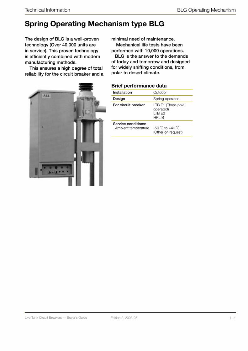
Live Tank Circuit Breakers — Buyer´s GuideK-8 Edition 2, 2003-06 Live Tank Circuit Breakers — Buyer´s Guide L-1Edition 2, 2003-06
Spring Operating Mechanism type BLG
The design of BLG is a well-proven technology (Over 40,000 units are in service). This proven technology is efficiently combined with modern manufacturing methods.
This ensures a high degree of total reliability for the circuit breaker and a
minimal need of maintenance. Mechanical life tests have been
performed with 10,000 operations.BLG is the answer to the demands
of today and tomorrow and designed for widely shifting conditions, from polar to desert climate.
Brief performance dataInstallation Outdoor
Design Spring operated
For circuit breaker LTB E1 (Three-poleoperated)LTB E2HPL B
Service conditions: Ambient temperature -50 ˚C to +40 ˚C
(Other on request)
Technical Information BLG Operating Mechanism

Live Tank Circuit Breakers — Buyer´s GuideL-2 Edition 2, 2003-06 Live Tank Circuit Breakers — Buyer´s Guide L-3Edition 2, 2003-06
MaterialThe housing is made of corrosion resistant, painted aluminum.
Front and back doors are equipped with doorstops and pad lock provisions on door handles.
The doors and walls are insulated for low heat energy consumption and low noise level.
Rating PlatesA rating plate, which includes data for the circuit breaker, is placed on the side of the cabinet.
The rating plate is made of stainless steel with engraved text.
InstructionsWith each delivery of circuit breakers, there is an extensive product manual that will guide the user how to handle the apparatus during its lifetime. Instructions, product manual, circuit diagram and other documents are placed in a compartment inside the back door of the operating mechanism.
Transport BLG is normally packed and transported in a separate seaworthy wooden box.
Arrival Inspection - UnpackingPlease check the contents and packaging with regard to transport damage immediately on arrival. In the event of any material missing or damage to the goods, contact ABB for advice, before further handling of the goods takes place. Any damage should be documented (photographed).
The operating mechanism must be lifted using the lifting eyes on top of the cabinet. Slings must not be placed around the cabi-net when lifting.
All packing material can be recycled.
StorageThe operating mechanism shall preferably be stored indoors in a dry building. When stored outdoors, the box should be opened to promote the exchange of air and the internal heater should be used to prevent condensation.
ToolsSpecial tools for assembling and service are placed on the backside of the rear door.
MaintenanceThe maintenance requirements are small, as BLG is designed for a service life of more than 30 years. Normally it is sufficient with ocular inspection every 1-2 years and some lubrication after 7-10 years or 2,000 close-open operations.
Preventive inspection is recommended after 15 years or 5,000 operations.
A more detailed check is recommended af-ter 30 years of service or 10,000 operations.
Overhaul and repair work must be performed by authorized personnel only.
The instructions in the manual for operation and maintenance should be observed. This ensures a continued problem-free operation.
DisposalThe disposal should be carried out in accordance with local legal provisions.
The metals used in BLG can be recycled.
BLG Operating Mechanism Technical Information
Spring Operating Mechanism type BLG

Live Tank Circuit Breakers — Buyer´s GuideL-2 Edition 2, 2003-06 Live Tank Circuit Breakers — Buyer´s Guide L-3Edition 2, 2003-06
Technical Information BLG Operating Mechanism
Electrical Functions
The principle function of the mechanism’s electrical components is shown in the elementary diagram on next page.
Closing CircuitThe closing coil (Y3) can be activated electrically by means of local or remote control. When the circuit breaker is in closed position, the closing circuit is interrupted by the auxiliary contact (BG).
Tripping CircuitsThe mechanism is provided with two independent trip coils (Y1 and Y2). The mechanism can be operated electrically through local or remote control. With the circuit breaker in the open position, the tripping circuits are interrupted by the auxiliary contact (BG).
InterlocksThe contact on the density switch (BD) actuates the auxiliary relays (K9, K10,), which block the operating impulse if the density of the SF6 gas is too low. The antipumping relay (K3) blocks any remaining closing impulse after the breaker has completed a closing operation.
The density of the SF6 gas and condition of the operating mechanism is monitored electrically, given the following (remote) indi-cations:• Topping up of SF6 gas is recommended
(alarm level)• Density of the SF6 gas is too low
(blocking level)• Direct-on-line motor starter switched off• Indication of charged springs
Heater CircuitsThe operating mechanism is provided with an anti-condensation heater.
To ensure reliable operation at low tem-peratures the mechanism is provided with a thermostat-controlled heater unit (BT1, E2).
Alternatively, in climatic conditions with high humidity, the mechanism can be provi-ded with moisture detector.
Terminal BlocksThe terminal blocks are the user’s interface to the control circuits and connect the internal wiring.Standard terminal blocks are compression type in which a bare wire end is compressed between two metallic plates in the terminal.
Circuits for supply to motor and AC auxiliaries are normally connected to 6 mm2 through-terminals. (Entrelec M6/8)
The signal circuits are connected to 4 mm2 through-terminals. (Entrelec M4/6)
As options the 6 mm2 terminals can be of the disconnectable type. (Entrelec M6/8.STA)
All terminals can be protected with a trans-parent cover.
Internal WiringThe cabling in the operating mechanism is normally carried out with PVC-insulated cables.
The dimensions are 2,5 mm2 for motor- circuits and 1,5 mm2 for control- and auxi-liary-circuits.
As an option flameproof, halogen free cable can be provided.

Live Tank Circuit Breakers — Buyer´s GuideL-4 Edition 2, 2003-06 Live Tank Circuit Breakers — Buyer´s Guide L-5Edition 2, 2003-06
Control CircuitsBD Signal contact of density switch
BG Auxiliary contact
BT1 Thermostat
BW Limit switch
E1, E2 Heater
F1, F1.1 Direct-on-line motor starter (MCB)
F2Miniature circuit breaker, AC auxiliary circuit
K3 Anti-pumping relay
Control CircuitsM, M.1 Motor
Q1, Q1.1 Contactor
S1 Switch, trip/close
S4 Selector switch (local/remote/disconn.)
Y1, Y2 Tripping coil
Y3 Closing coil
Y7Blocking contact(Hand crank adapted)
BLG Operating Mechanism Technical Information
CLOSE TRIP 1 TRIP 2
SIGNALS MOTOR HEATER
BLG Circuit Diagram
Circuit diagram shows operating mechanism when circuit breaker is in normal service condition, i.e. pressurized, closing spring charged, in closed position, in motor charging position, and with selector switch in remote position.
SPO = Single-pole operatedTPO = Three-pole operated
N = NeutralL = Live
Two motors are used
in the BLG when
larger spring energy is
required.
Electrical Functions
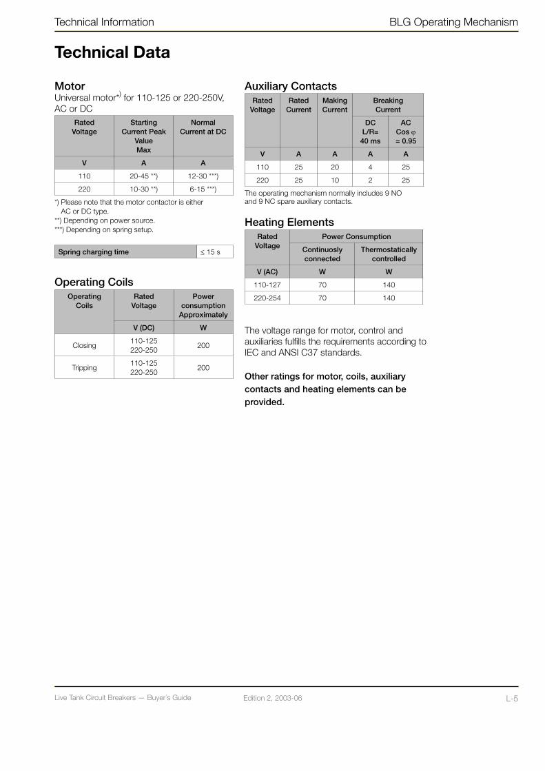
Live Tank Circuit Breakers — Buyer´s GuideL-4 Edition 2, 2003-06 Live Tank Circuit Breakers — Buyer´s Guide L-5Edition 2, 2003-06
Technical Information BLG Operating Mechanism
Technical Data
MotorUniversal motor*) for 110-125 or 220-250V, AC or DC
RatedVoltage
StartingCurrent Peak
ValueMax
NormalCurrent at DC
V A A
110 20-45 **) 12-30 ***)
220 10-30 **) 6-15 ***)
*) Please note that the motor contactor is either AC or DC type.**) Depending on power source.***) Depending on spring setup.
Spring charging time ≤ 15 s
Operating CoilsOperating
CoilsRated
VoltagePower
consumptionApproximately
V (DC) W
Closing110-125220-250
200
Tripping110-125220-250
200
Auxiliary ContactsRated
VoltageRated
CurrentMakingCurrent
BreakingCurrent
DCL/R=40 ms
ACCos ϕ= 0.95
V A A A A
110 25 20 4 25
220 25 10 2 25
The operating mechanism normally includes 9 NO and 9 NC spare auxiliary contacts.
Heating ElementsRated
VoltagePower Consumption
Continuoslyconnected
Thermostaticallycontrolled
V (AC) W W
110-127 70 140
220-254 70 140
The voltage range for motor, control and auxiliaries fulfills the requirements according to IEC and ANSI C37 standards.
Other ratings for motor, coils, auxiliary contacts and heating elements can be provided.

Live Tank Circuit Breakers — Buyer´s GuideL-6 Edition 2, 2003-06 Live Tank Circuit Breakers — Buyer´s Guide L-7Edition 2, 2003-06
Design Data
Dimensions (mm) 682 x 760 x 747
Weight (kg) 465
Material of Housing Aluminium
Thickness (mm) 2
Color Grey, RAL 7032
Temperature range ˚C -50 to + 70
Degree of Protection As per IEC 60529: IP 55
Terminal BlocksSupply, motor and AC circuits, disconnectable 6 mm2 block.
Signal circuits through 4 mm2 block.
Cable Connection Size FL 33: 102 x 306
Earthing Clamp For conductors with maximum 13 mm diameter
Internal CableMotor circuits 2,5 mm2 PVC-insulated cable.
Otherwise 1,5 mm2 PVC-insulated cable.
BLK
Cable Entry Flange (FL 33)
Front View
Bottom View
Side View
BLG Operating Mechanism Technical Information

Live Tank Circuit Breakers — Buyer´s GuideL-6 Edition 2, 2003-06 Live Tank Circuit Breakers — Buyer´s Guide L-7Edition 2, 2003-06
Technical Information BLG Operating Mechanism
Design Data
Optional Equipment• Manual mechanical trip push-button -
Inside or outside cubicle• Additional auxiliary contacts - 6 NO + 6 NC • Trip circuit supervision• Internal light with door switch• Socket outlet• Position indicating lights• Extra heater with MCB - Moisture detector
control• Provision for key interlock (Castell, Fortress
or Kirk)• Extra closing coil• Lockable operating switches• Protective cover for terminal block
TestsThe BLG mechanism has together with the corresponding circuit breaker, passed type tests in accordance with applicable IEC and ANSI standards.
Mechanical life tests have been performed with 10,000 operations.
Before delivery each operating mechanism together with the corresponding circuit brea-ker has to pass routine tests according to current standards.
For each circuit breaker together with its operating mechanism a routine test report is issued showing the actual test result.
Recommended Spare Parts for BLGApplicable for circuit breakers for frequent switching duty, e.g. switching capacitor- or reactor-banks.• Catchgear with closing coil (or separate coil)• Catchgear with tripping coils (or separate coil)• Heater• Motor with driving unit• Motor contactor• Auxiliary relays
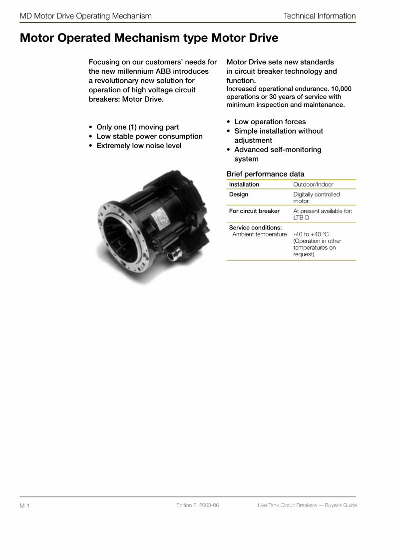
Live Tank Circuit Breakers — Buyer´s GuideM-1 Edition 2, 2003-06 Live Tank Circuit Breakers — Buyer´s Guide M-2Edition 2, 2003-06
MD Motor Drive Operating Mechanism Technical Information
Motor Operated Mechanism type Motor Drive
Focusing on our customers’ needs for the new millennium ABB introduces a revolutionary new solution for operation of high voltage circuit breakers: Motor Drive.
• Only one (1) moving part• Low stable power consumption• Extremely low noise level
Motor Drive sets new standards in circuit breaker technology and function.Increased operational endurance. 10,000 operations or 30 years of service with minimum inspection and maintenance.
• Low operation forces• Simple installation without adjustment• Advanced self-monitoring system
Brief performance dataInstallation Outdoor/Indoor
Design Digitally controlled motor
For circuit breaker At present available for:LTB D
Service conditions: Ambient temperature -40 to +40 oC
(Operation in other temperatures on request)

Live Tank Circuit Breakers — Buyer´s GuideM-1 Edition 2, 2003-06 Live Tank Circuit Breakers — Buyer´s Guide M-2Edition 2, 2003-06
Technical Information MD Motor Drive Operating Mechanism
Technical data
Power Supply
Input Rated voltage1 (V)
1 and 2 110 - 250 V DC (-30% — + 110%)220 - 240 V AC (-30% — + 110%)
1 Two alternative galvanic separated supplies. If there is a 230 V AC supply, this supply will be used as primary supply. If not, the electronics automatically without interruption will switch to 110 V DC supply.
Maximum power required at rated supply voltage
During startup of the system
On-line without operations
During and immediately fol-lowing a single
operation< 10s
< 100 ms, 550 W< 60 s, 350 W < 100 W < 400 W
Control Circuits
Control circuit Rated voltage(V DC)
Current or power
Close input 110220 on request
160 mA during the first 3 ms, then 3 mA
Trip input 110220 on request
160 mA during the first 3 ms, then 3 mA
Others 110220 on request
160 mA during the first 3 ms, then 3 mA
Outputs
Output Nom. rated current
(A)
Breaking capacity
Resistive load (V DC)
Max. Breaking current
(A)
Indication closed posi-tion
16 110250
0.450.35
Indication open position 16 110
2500.450.35
Indication cir-cuit breaker fault
16 110250
0.450.35
Others 16 110250
0.450.35
Serial Communication Port
Output Connector type Compatible optical fibre
Fibre output ST 62.5/125 µmnom. 820 nm
Heating Element
Power consumption
Rated voltage (V, AC/DC)
Thermostatically controlledPlaced in Control cubicle
110 - 230 2 x 100 W (at 20°C)
Test Voltage 1 min. 50 Hz
Circuit Voltage (kV)
Voltage supply 2
Control circuits 2
Outputs 2
Heating element 2
Operating Times
Opening times 22 ms
Closing times 45 ms
Rated operating sequence O - 0.3 s - CO - 3 min - COCO - 15 s - CO
Dimensions
Control cubicle
Dimension (mm) 885 x 1345 x 787
Weight (kg) 190
Thickness 2 mm aluminium
Color Grey
Temperature range -40ºC to +70ºC
Degree of protection As per IEC 60529: IP 55
Terminal blocksSupply, control and AC-circuits
isolatable 6 mm2 block. Signal circuits through 4 mm2 block.
Cable-entry flange (mm)
Size FL33, two flanges2 x (102 x 306)
Earthing clamp For conductor with max. 13 mm diameter
Internal cable 1.5 mm2 PVC insulated cable
Testing
The motor drive has successfully passed the following type tests
Mechanical, High/Low temperature and power according IEC and ANSI
EMC according IEC and EN
Mechanical life tests have been performed with 10,000 operations.
Before delivery each motor drive has to pass routine tests confor-ming to current standards. For each breaker a routine test report is issued showing the actual test result.

Live Tank Circuit Breakers — Buyer´s GuideN-1 Edition 2, 2003-06 Live Tank Circuit Breakers — Buyer´s Guide N-2Edition 2, 2003-06
Composite Insulators
ABB has developed a full range of high voltage equipment including surge arresters, instrument transformers and circuit breakers with high performance and robust composite insulation as an alternative to porcelain. Use of composite insulators provides new possibilities for substation designers to improve safety and availability.
GeneralComposite insulators with silicone rubber sheds (SIR) offer many advantages over traditional porcelain insulators:
Non-brittle • Lower transport and handling risk• Lower in-service risks• Low risk for damages by vandalism
Low weight• Easier handling• Reduced foundation loads• Excellent seismic withstand
Hydrophobic• Less maintenance• Suppressed leakage currents
Demands on Composite Insulator Demands on insulators used for gas insulated live tank circuit breakers are high with respect to mechanical loads as well as electrical stresses. The insulator shall also withstand the decomposed SF6 gas and the heat developed during current interruption.
ABB Manufacturing Techniques The supporting part of the insulator consists of a cross-laminated fi berglass reinforced epoxy tube, joined to metal end fl anges. The glass fi bers on the inner surface of the hollow insulator are protected against the infl uence of the SF6 decomposition products by a liner of epoxy, reinforced with polyester fi bers.
The patented helical extrusion moulded silicone rubber insulator without joints (che-mical bonds between spirals) is attached to the tube by the spiral winding process, developed by ABB. It minimizes electrical fi eld concentrations and reduces build up of contamination.
ColorThe (SIR) insulators for the circuit breakers are delivered in light gray color.
ApplicationsComposite insulators are used for the following types of ABB live tank circuit breakers:
LTB 72.5-550 kVHPL 72.5-800 kV
Completed Tests PerformedOn Insulator
Accelerated ageing test (1,000 h)
UV radiation tests
Natural pollution test
On Circuit Breaker
Seismic
Overpressure
Shatter
Dielectric
Short-time current
High and low temperature
Main parts of ABB´s composite insulator:1. Metal Flange | 2. Glass fi ber reinforced epoxy tube | 3. Liner | 4. Silicone Rubber Shed
LTB Circuit Breaker with composite insulator.
Composite Insulators Technical Information
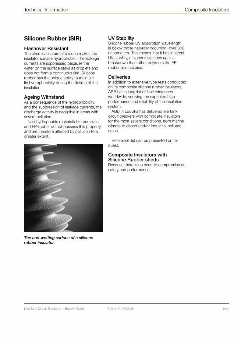
Live Tank Circuit Breakers — Buyer´s GuideN-1 Edition 2, 2003-06 Live Tank Circuit Breakers — Buyer´s Guide N-2Edition 2, 2003-06
Silicone Rubber (SIR)
Flashover ResistantThe chemical nature of silicone makes the insulator surface hydrophobic. The leakage currents are suppressed because the water on the surface stays as droplets and does not form a continuous film. Silicone rubber has the unique ability to maintain its hydrophobicity during the lifetime of the insulatior.
Ageing WithstandAs a consequence of the hydrophobicity and the suppression of leakage currents, the discharge activity is negligible in areas with severe pollution.
Non-hydrophobic materials like porcelain and EP-rubber do not possess this property and are therefore affected by pollution to a greater extent.
UV StabilitySilicone rubber UV absorption wavelength is below those naturally occurring -over 300 nanometers. This means that it has inherent UV stability, a higher resistance against breakdown than other polymers like EP-rubber and epoxies.
DeliveriesIn addition to extensive type tests conducted on its composite silicone rubber insulators, ABB has a long list of field references worldwide, verifying the expected high performance and reliability of the insulation system.
ABB in Ludvika has delivered live tank circuit breakers with composite insulators for the most severe conditions, from marine climate to desert and/or industrial polluted areas.
Reference list can be presented on re-quest.
Composite Insulators with Silicone Rubber shedsBecause there is no need to compromise on safety and performance.
The non-wetting surface of a silicone rubber insulator
Technical Information Composite Insulators

Live Tank Circuit Breakers — Buyer´s GuideO-1 Edition 2, 2003-06 Live Tank Circuit Breakers — Buyer´s Guide O-2Edition 2, 2003-06
Controlled Switching Technical Information
Controlled Switching with SwitchsyncTM
Suppression of Switching TransientsThere are several important circuit breaker applications where random making or breaking operations may lead to severe voltage and current switching transients. The transients occur in the main circuits, but may also lead to induced transients in control and auxiliary circuits, as well as in adjacent low voltage systems. The switching transients are associated with a variety of dielectric and mechanical stresses on the high-voltage equipment, and may cause gradual or immediate damage. Induced transients may lead to a variety of different disturbances, e.g. in substation control and protection systems, computers/processors, or telecommunications.
Energizing shunt capacitors, shunt reac-tors, and power transformers may cause severe transients - high overvoltages, under-voltages, or high inrush currents. When de-energizing capacitive loads, harmonic fi lters or shunt reactors, restrikes or re-ignitions may occur, resulting in steep voltage surges. The magnitude of the transients depends on the point-on-wave where opening or closing of the breaker contacts occur. In an uncon-trolled situation, sooner or later switching is bound to occur at the worst possible points-on-wave.
Conventional countermeasures such as pre-insertion resistors, damping reactors, or arresters are used in order to limit the magnitude of the switching transients, and insulation may be upgraded to withstand the stresses. These methods may be ineffi cient, unreliable, or expensive, and do not treat the root of the problem: Sooner or later, uncon-trolled switching is bound to occur at the worst possible points-on-wave.
By means of SwitchsyncTM relays, both energizing and de-energizing can be con-trolled with regard to the point-on-wave position, and no harmful transients will be generated.
ExperienceABB has long service experience with controlled switching, and the fi rst generation of Switchsync™ was launched in 1986. ABB is in the forefront of this development and has built up unique competence about switching transients and mitigation of the related problems in both main and secondary circuit, as well as the EMC aspects.
Since 1984 more than 1,500 SwitchsyncTM devices have been delivered.
Switching of Capacitor BanksSwitchsync™ for capacitor bank breakers are normally used for control of the closing operations. A discharged capacitor is similar to a momentary short-circuit when connected to a power source. If energized when the source voltage is high, the connection results in voltage and current transients that may cause serious problems. Depending on the network confi guration, the voltage surge may cause breakdown somewhere in the high voltage network, and low voltage equipment may suffer insulation damage or malfunction. With back-to-back capacitor banks, the inrush current may be steep and high enough to threaten the mechanical integrity of both capacitors and breaker. Controlling the breaker to energize a capacitive load at source voltage zero will eliminate harmful transients.
Figure 1.
Voltage transients when energizing one phase of a
72 kV capacitor bank
a. At an unsuitable point-on-wave position, close to
the power frequency voltage peak. A high voltage
transient is generated.
b. With SwitchsyncTM. Energizing occurs
close to voltage zero, and no transient is
generated.
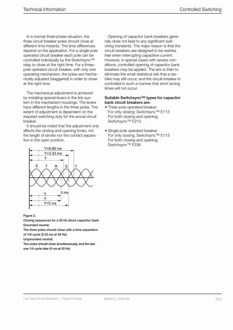
Live Tank Circuit Breakers — Buyer´s GuideO-1 Edition 2, 2003-06 Live Tank Circuit Breakers — Buyer´s Guide O-2Edition 2, 2003-06
Opening of capacitor bank breakers gene-rally does not lead to any significant swit-ching transients. The major reason is that the circuit breakers are designed to be restrike free when interrupting capacitive current. However, in special cases with severe con-ditions, controlled opening of capacitor bank breakers may be applied. The aim is then to eliminate the small statistical risk that a res-trike may still occur, and the circuit-breaker is controlled in such a manner that short arcing times will not occur.
Suitable SwitchsyncTM types for capacitor bank circuit breakers are: • Three-pole operated breaker: For only closing; Switchsync™ E113
For both closing and opening; Switchsync™ E213
• Single-pole operated breaker:For only closing; Switchsync™ E113 For both closing and opening; Switchsync™ F236
Technical Information Controlled Switching
In a normal three-phase situation, the three circuit breaker poles should close at different time instants. The time differences depend on the application. For a single-pole operated circuit breaker each pole can be controlled individually by the Switchsync™ relay to close at the right time. For a three-pole operated circuit breaker, with only one operating mechanism, the poles are mecha-nically adjusted (staggered) in order to close at the right time.
The mechanical adjustment is achieved by installing special levers in the link sys-tem in the mechanism housings. The levers have different lengths in the three poles. The extent of adjustment is dependent on the required switching duty for the actual circuit breaker.
It should be noted that the adjustment only affects the closing and opening times, not the length of stroke nor the contact separa-tion in the open position.
Figure 2.
Closing sequences for a 50 Hz shunt capacitor bank
Grounded neutral:
The three poles should close with a time separation
of 1/6 cycle (3.33 ms at 50 Hz)
Ungrounded neutral:
Two poles should close simultaneously, and the last
one 1/4 cycle later (5 ms at 50 Hz)
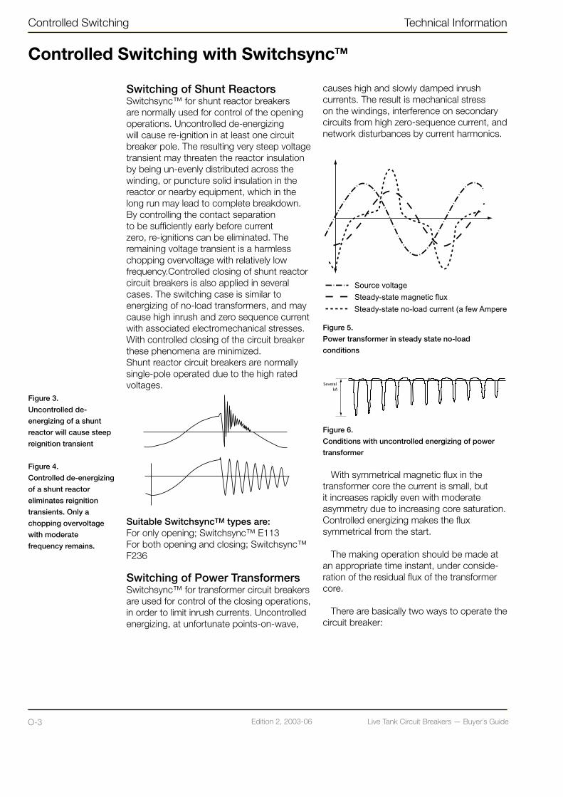
Live Tank Circuit Breakers — Buyer´s GuideO-3 Edition 2, 2003-06 Live Tank Circuit Breakers — Buyer´s Guide O-4Edition 2, 2003-06
causes high and slowly damped inrush currents. The result is mechanical stress on the windings, interference on secondary circuits from high zero-sequence current, and network disturbances by current harmonics.
Figure 5.
Power transformer in steady state no-load
conditions
Figure 6.
Conditions with uncontrolled energizing of power
transformer
With symmetrical magnetic flux in the transformer core the current is small, but it increases rapidly even with moderate asymmetry due to increasing core saturation. Controlled energizing makes the flux symmetrical from the start.
The making operation should be made at an appropriate time instant, under conside-ration of the residual flux of the transformer core.
There are basically two ways to operate the circuit breaker:
Controlled Switching Technical Information
Switching of Shunt ReactorsSwitchsync™ for shunt reactor breakers are normally used for control of the opening operations. Uncontrolled de-energizing will cause re-ignition in at least one circuit breaker pole. The resulting very steep voltage transient may threaten the reactor insulation by being un-evenly distributed across the winding, or puncture solid insulation in the reactor or nearby equipment, which in the long run may lead to complete breakdown. By controlling the contact separation to be sufficiently early before current zero, re-ignitions can be eliminated. The remaining voltage transient is a harmless chopping overvoltage with relatively low frequency.Controlled closing of shunt reactor circuit breakers is also applied in several cases. The switching case is similar to energizing of no-load transformers, and may cause high inrush and zero sequence current with associated electromechanical stresses. With controlled closing of the circuit breaker these phenomena are minimized.Shunt reactor circuit breakers are normally single-pole operated due to the high rated voltages.
Suitable SwitchsyncTM types are:For only opening; Switchsync™ E113 For both opening and closing; Switchsync™ F236
Switching of Power TransformersSwitchsync™ for transformer circuit breakers are used for control of the closing operations, in order to limit inrush currents. Uncontrolled energizing, at unfortunate points-on-wave,
Figure 3.
Uncontrolled de-
energizing of a shunt
reactor will cause steep
reignition transient
Figure 4.
Controlled de-energizing
of a shunt reactor
eliminates reignition
transients. Only a
chopping overvoltage
with moderate
frequency remains.
Controlled Switching with SwitchsyncTM

Live Tank Circuit Breakers — Buyer´s GuideO-3 Edition 2, 2003-06 Live Tank Circuit Breakers — Buyer´s Guide O-4Edition 2, 2003-06
Technical Information Controlled Switching
1. The opening operations of the breaker are controlled, in order to achieve a defined and repeatable residual magnetic flux in the transformer core. The procedure is normally to interrupt the no-load current close to a natural zero passage, which results in a residual flux close to zero in the core. The subsequent closing operation is then controlled in order to minimize the inrush current, based on this knowledge. This method is suitable for regular planned switching of transformers under no-load conditions. Suitable device is Switchsync™ F236.
2. The opening operations are performed uncontrolled, while the resulting residual flux is determined by means of measurements and integration of the transformer voltage. Based on the calculated residual flux, the subsequent closing operation is then controlled in such a manner that the inrush current is minimized. In this mood of operation the residual flux may vary considerably from operation to operation, and the actual making operations will take place at varying time instants in relation to the supply voltage. This method is mainly suitable for situations with unplanned operations, under varying switching conditions. Since each pole needs to be controlled independently, the method does require single pole operation of the transformer breaker. Suitable device is Switchsync™ T183.
Switching of EHV LinesThe traditional method for limitation of switching overvoltages during closing or reclosing operations of unloaded EHV lines is to use circuit breakers equipped with closing resistors. However, controlled switching of the line circuit breakers is increasingly considered as an alternative, and then often as part of a solution where surge arresters are also applied for optimal limitation of the switching overvoltages. Circuit breakers at this voltage level are generally single pole operated.
For uncompensated lines, controlled switching of the circuit breakers may be arranged in two different ways:
Trapped charge on the line, resulting from the opening operation, is not recor-ded. When closing, the circuit breaker is controlled to make the current approx-imately when the instantaneous voltage in the substation is zero. In this manner limitation of high overvoltages is achie-ved irrespective of the actual trapped charge. This is a straightforward method, and often the resulting overvoltage level is acceptable, especially when applied in combination with surge arresters. In many cases the trapped charge will actually be zero or close to zero. This will be the case when sufficient time has elapsed from the opening operation, or even at rapid re-closing operations, if the line is equipped with magnetic voltage transformers.Suitable device is Switchsync™ F236.
More efficient limitation of the switching overvoltages is achieved when the trap-ped charge on the line is recorded, and taken into consideration by the controlling device. This solution is especially useful in situations when considerable trapped charge is to be expected; i.e. for rapid reclosing operations in situations when CVTs are used. The magnitude of the trap-ped charge can be recorded by the CVTs.Suitable device is Switchsync™ L183.
For shunt compensated lines, the in-teraction between line capacitance and reactor inductance will lead to a voltage oscillation on the line after interruption. Due to different frequencies on both sides, there will be a beat frequency voltage shape across the open circuit breaker. In this case, due to the oscillating voltage shape on the line, CVTs will provide cor-rect voltage signals. Controlled making of the circuit breaker should be made at a beat frequency minimum, or at voltage mi-nimum at the supply side. Suitable device is Switchsync F236, or CAT.

Live Tank Circuit Breakers — Buyer´s GuideO-5 Edition 2, 2003-06 Live Tank Circuit Breakers — Buyer´s Guide O-6Edition 2, 2003-06
Controlled Switching Technical Information
The function principle is further illustrated in Figure 8. After the relay has received a switching command (1), it chooses a reference instant (2) that conforms to certain precision-enhan-cing criteria, and starts waiting for the best instant (6) to pass on output command to the breaker. The waiting time (5) is calculated by the relay based on the switching instant target (3) and an expected switching time (4). In adaptive operation, the actual switching instant (7) is detected and compared with the target instant. If these disagree because the actual switching time (8) differs from the ex-pected, the relay adjusts its waiting time (10) for the next operation by half the error (9). In this way, the expected switching time (12) is based on a continuously updated weighted history of earlier operations, and the output command (11) is adapted to minimize devia-tions (13) from the optimal switching instant.
Figure 8.
Function principle of Switchsync™
Figure 7.
Example of SwitchsyncTM installation:
1. Synchronizing relay, in this case Switchsync™
E113.
2. Voltage transformer supplying a phase reference
signal.
3. Current transformer supplying signal used for
detecting instant of current onset.
4. Input closing command from control system.
5. Synchronized output command to operating
mechanism.
6. Circuit breaker.
7. Time separation between poles achieved by
mechanical means.
Connection of SwitchsyncTM; Adaptive ControlIn Figure 7, the function of Switchsync™ is illustrated using a simple application: closing of a three-pole operated breaker to energize a capacitor bank with grounded neutral.
In this application each breaker pole is to be closed when the respective phase-to-ground source voltage is zero.
Controlled Switching with SwitchsyncTM

Live Tank Circuit Breakers — Buyer´s GuideO-5 Edition 2, 2003-06 Live Tank Circuit Breakers — Buyer´s Guide O-6Edition 2, 2003-06
Number of command inputs (open or close)
Number of adaptive channels
Number of command outputs to controlled circuit breaker
Technical Information Controlled Switching
Range of SwitchsyncTM
The main functions of the family of Switchsync™ are summarized in the following table: Model Controls CB Operation Adaptive Input Predictive Input Memory for
switching times
E113 Open or Close 1 or 3-pole Yes No No
E213 Open or Close 3-pole Yes No No
F236 Open or Close 1-pole Yes Yes Yes
T183 Close 1-pole Yes Yes Yes
L183 Close 1-pole Yes Yes Yes
Switchsync™ F, T & L have provisions for two external, predictive inputs (e.g. temperature variation, control
voltage). These functions make it possible to achieve added precision in the timing of the controlled circuit
breaker. They also have a data memory that stores information of switching times, and thereby permit
condition monitoring of the circuit breaker.
Type DesignationThe type designation of a Switchsync™ relay gives information about its functionality.
The letter is a generation and application identification, while the subsequent numbers provide the following information:
Figure 9. Switchsync™ F236 and E113 relays
Figure 10. Switchsync™ L183 relay
Figure 11. Switchsync™ T183 relay
Live Tank Circuit Breakers — Buyer´s GuideP-1 Edition 2, 2003-06 Live Tank Circuit Breakers — Buyer´s Guide P-2Edition 2, 2003-06
Monitoring Technical Information
On-Line Monitoring System OLM2
The OLM2 monitor is a measuring data acquisition unit optimized for on-line analysis of high-voltage circuit breakers. The electronic circuit is fitted into an EMC shielded aluminum profile housing. The aluminum housing has screw terminals for all external connections.
Communication to and from the monitoring units within a substation is done through an OLM-bus (a modified RS 485 bus), using twisted screened copper cables. One bus can handle 31 OLM2 units. To communicate with a computer directly an OLM bus conver-ter (RS 485 to RS 232) must be used.
From the substation to the location where analysis is performed, data can be transmit-ted using any existing communication means compatible with the RS 232 signal standard. External systems, such as SCADA can easily make use of the data obtained through the OLM.
Data acquisition starts when the OLM is triggered by either a coil input (trip or close) or an input to the motor of the operating mechanism. For each operation of the circuit breaker a complete image of the recorded parameters is stored into the unit, including local time and temperature (ambient and in-side operating mechanism). The stored data is then accessible for analysis using the OLM Explore software. With this tool a detailed analysis of all circuit-breaker parameters is
possible including trend analysis.The following parameters may be monito-
red: operating times, coil currents, contact travel (giving information about speed, over-travel and damping), motor current including spring charging time, SF
6-density. Phase
currents can be measured as an option to determine the life of the contacts.
DesignThe OLM system consists of a signal processor with programmable logic. Most internal functions can be modified by software changes, which means that it can easily be adapted to any type of equipment. The OLM system has its own internal watchdog with alarm function.The software provided together with the OLM consists of three parts:• OLM Installer, used for installation of the
individual units• OLM Server, used for communication
from a central location• OLM Explorer, the data analysis and
supervision tool
Example of the presentation of the motor current
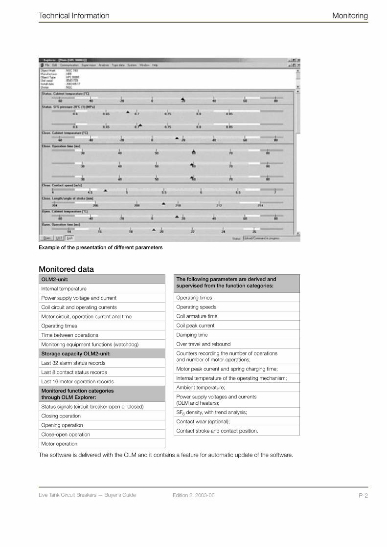
Live Tank Circuit Breakers — Buyer´s GuideP-1 Edition 2, 2003-06 Live Tank Circuit Breakers — Buyer´s Guide P-2Edition 2, 2003-06
Technical Information Monitoring
Monitored dataOLM2-unit:
Internal temperature
Power supply voltage and current
Coil circuit and operating currents
Motor circuit, operation current and time
Operating times
Time between operations
Monitoring equipment functions (watchdog)
Storage capacity OLM2-unit:
Last 32 alarm status records
Last 8 contact status records
Last 16 motor operation records
Monitored function categories through OLM Explorer:
Status signals (circuit-breaker open or closed)
Closing operation
Opening operation
Close-open operation
Motor operation
Example of the presentation of different parameters
The following parameters are derived and supervised from the function categories:
Operating times
Operating speeds
Coil armature time
Coil peak current
Damping time
Over travel and rebound
Counters recording the number of operations and number of motor operations;
Motor peak current and spring charging time;
Internal temperature of the operating mechanism;
Ambient temperature;
Power supply voltages and currents (OLM and heaters);
SF6 density, with trend analysis;
Contact wear (optional);
Contact stroke and contact position.
The software is delivered with the OLM and it contains a feature for automatic update of the software.
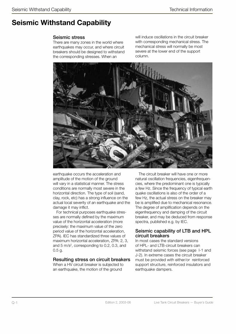
Live Tank Circuit Breakers — Buyer´s GuideQ-1 Edition 2, 2003-06 Live Tank Circuit Breakers — Buyer´s Guide Q-2Edition 2, 2003-06
Seismic stressThere are many zones in the world where earthquakes may occur, and where circuit breakers should be designed to withstand the corresponding stresses. When an
earthquake occurs the acceleration and amplitude of the motion of the ground will vary in a statistical manner. The stress conditions are normally most severe in the horizontal direction. The type of soil (sand, clay, rock, etc) has a strong influence on the actual local severity of an earthquake and the damage it may inflict.
For technical purposes earthquake stres-ses are normally defined by the maximum value of the horizontal acceleration (more precisely: the maximum value of the zero period value of the horizontal acceleration, ZPA). IEC has standardized three values of maximum horizontal acceleration, ZPA: 2, 3, and 5 m/s2, corresponding to 0.2, 0.3, and 0.5 g.
Resulting stress on circuit breakersWhen a HV circuit breaker is subjected to an earthquake, the motion of the ground
Seismic Withstand Capability Technical Information
Seismic Withstand Capability
will induce oscillations in the circuit breaker with corresponding mechanical stress. The mechanical stress will normally be most severe at the lower end of the support column.
The circuit breaker will have one or more natural oscillation frequencies, eigenfrequen-cies, where the predominant one is typically a few Hz. Since the frequency of typical earthquake oscillations is also of the order of a few Hz, the actual stress on the breaker may be is amplified due to mechanical resonance. The degree of amplification depends on the eigenfrequency and damping of the circuit breaker, and may be deduced from response spectra, published e.g. by IEC.
Seismic capability of LTB and HPL circuit breakersIn most cases the standard versions of HPL- and LTB-circuit breakers can withstand seismic forces (see page I-1 and J-2). In extreme cases the circuit breaker must be provided with either/or reinforced support structure, reinforced insulators and earthquake dampers.

Live Tank Circuit Breakers — Buyer´s GuideQ-1 Edition 2, 2003-06 Live Tank Circuit Breakers — Buyer´s Guide Q-2Edition 2, 2003-06
Technical Information Seismic Withstand Capability
Earthquake dampersAn earthquake damper will reduce the lowest eigenfrequency of the circuit breaker and at the same time increase the damping. In this way the amplification of earthquake stresses due to resonance is significantly decreased, and the maximum mechanical stress on the circuit breaker significantly reduced.
Fig. 1. illustrates the principle of a damping unit. The support frame (1) is mounted on the bottom plate (3) on which four damping cylinders (2) are assembled. The piston rods (4) are fixed to the foundation bolts. Between the piston rod and the cylinder there is a piston system working, which is absorbing friction energy during motion. This provides damping for the complete circuit breaker.
Since the circuit breaker is hanging in the dampers, the forces of inertia during an earthquake can easily initialize the motion of the dampers without having to overcome the forces of gravity.
Fig. 1. Support column of HV circuit breaker with earthquake damping unit.
Verification of seismic capabilityThe seismic capability of a circuit breaker may be verified by a direct test, where a complete circuit breaker, or pole, is subjected to simulated earthquake stress on a shaker table. See Fig. 2.
An alternative method is to determine the eigenfrequencies and damping of the circuit breaker. This can be done e.g. by a snap-back test, where a mechanical stress is app-lied to the breaker, and suddenly released. Based on eigenfrequencies and damping, the resulting mechanical stress in critical parts of the breaker may be determined by means of calculations.
Fig. 2. 550 kV circuit breaker subjected to earthquake test on a shaker table. The highest mechanical stress occurs in the lower end of the vertical support column.The circuit breaker is equipped with composite insulators.
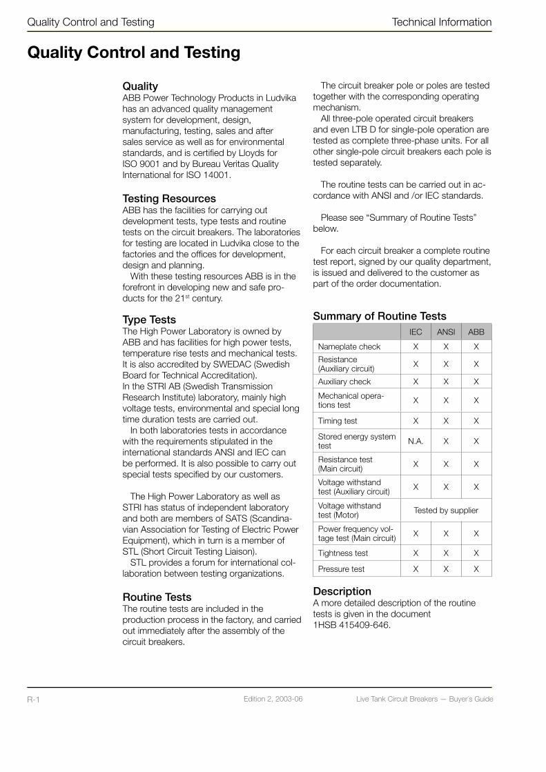
Live Tank Circuit Breakers — Buyer´s GuideR-1 Edition 2, 2003-06 Live Tank Circuit Breakers — Buyer´s Guide R-2Edition 2, 2003-06
Quality Control and Testing Technical Information
Quality Control and Testing
QualityABB Power Technology Products in Ludvika has an advanced quality management system for development, design, manufacturing, testing, sales and after sales service as well as for environmental standards, and is certified by Lloyds for ISO 9001 and by Bureau Veritas Quality International for ISO 14001.
Testing ResourcesABB has the facilities for carrying out development tests, type tests and routine tests on the circuit breakers. The laboratories for testing are located in Ludvika close to the factories and the offices for development, design and planning.
With these testing resources ABB is in the forefront in developing new and safe pro-ducts for the 21st century.
Type TestsThe High Power Laboratory is owned by ABB and has facilities for high power tests, temperature rise tests and mechanical tests. It is also accredited by SWEDAC (Swedish Board for Technical Accreditation).In the STRI AB (Swedish Transmission Research Institute) laboratory, mainly high voltage tests, environmental and special long time duration tests are carried out.
In both laboratories tests in accordance with the requirements stipulated in the international standards ANSI and IEC can be performed. It is also possible to carry out special tests specified by our customers.
The High Power Laboratory as well as STRI has status of independent laboratory and both are members of SATS (Scandina-vian Association for Testing of Electric Power Equipment), which in turn is a member of STL (Short Circuit Testing Liaison).
STL provides a forum for international col-laboration between testing organizations.
Routine TestsThe routine tests are included in the production process in the factory, and carried out immediately after the assembly of the circuit breakers.
The circuit breaker pole or poles are tested together with the corresponding operating mechanism.
All three-pole operated circuit breakers and even LTB D for single-pole operation are tested as complete three-phase units. For all other single-pole circuit breakers each pole is tested separately.
The routine tests can be carried out in ac-cordance with ANSI and /or IEC standards.
Please see “Summary of Routine Tests” below.
For each circuit breaker a complete routine test report, signed by our quality department, is issued and delivered to the customer as part of the order documentation.
Summary of Routine TestsIEC ANSI ABB
Nameplate check X X X
Resistance (Auxiliary circuit) X X X
Auxiliary check X X X
Mechanical opera-tions test X X X
Timing test X X X
Stored energy system test N.A. X X
Resistance test (Main circuit) X X X
Voltage withstand test (Auxiliary circuit) X X X
Voltage withstand test (Motor) Tested by supplier
Power frequency vol-tage test (Main circuit) X X X
Tightness test X X X
Pressure test X X X
DescriptionA more detailed description of the routine tests is given in the document 1HSB 415409-646.
Live Tank Circuit Breakers — Buyer´s GuideR-1 Edition 2, 2003-06 Live Tank Circuit Breakers — Buyer´s Guide R-2Edition 2, 2003-06
Technical Information Quality Control and Testing
Processes and Support
The circuit breaker organization is process-oriented with focus on deliveries to customers. The process is continuously optimized with respect to time and quality.
Sales & Order HandlingIn order to assure that the deliveries fullfill the requirements in the Purchase Order (P.O.) special attention is focused on:• Assuring the handover of the P.O. from the
Sales to the Order department.• Order clarification, assuring the particular
tasks of order, order design, purchasing and production departments.
• Possible order modifications.
The tools to monitor the orders are continuously improved in order to give our customers the best possible service.
Supply Management & PurchasingThe circuit breaker unit has well defined processes for selection and approval of suppliers.
Special attention is addressed to audits at the suppliers plant, the manufacturing, In-spection and Test Plan (ITP) and the On Time Delivery (OTD) monitoring.
The suppliers are evaluated at regular inter-vals with respect to quality and ODT.
Production & AssemblyAll employees are trained and certified with respect to their responsibilities. Inspections and test plans together with inspection records and control cards have been prepared for all circuit breakers in order to assure that all activities and the assembly are performed according to the specification.
Service & SparesThe circuit breaker unit takes care of the customer’s requirements with respect to service and spare parts. Certified traveling service engineers are available at the plant in Ludvika. Also, in order to be able to assist our customers as fast as possible, local service centers are established in several parts of the world.
In case of emergencies a 24-hour telephone support is available (ph.: +46 70 3505350).By calling this number customers will get in touch with one of our representatives for immediate consultancy and action planning.
Research & DevelopmentThe R&D process is utilizing a project management model with well-defined gates in order to assure that all customer requirements and technical issues are addressed.

Live Tank Circuit Breakers — Buyer´s GuideS-1 Edition 2, 2003-06 Live Tank Circuit Breakers — Buyer´s Guide S-2Edition 2, 2003-06
Enquiry Data for Live Tank Circuit Breakers
As a minimum the following information is required and can preferably be copied and sent along with your inquiry.
PROJECT DATA
End customer
Name of project
Standard / Customer specification
Number of circuit breakers
Delivery time
APPLICATION
Line
Transformer
Reactor banks
Capacitor banks
Other service duty
SYSTEM PARAMETERS
Rated voltage
Rated frequency
Rated normal current
Maximum breaking current
LIWL (Lightning impulse 1.2/50 µs)
SIWL (Switching impulse 25/2500 µs, for Um >300 kV)
Power frequency withstand voltage
Grounded / Ungrounded neutral
AMBIENT CONDITIONS
Ambient temperature (max - min)
Altitude (m.a.s.l.)
Earthquake withstand requirements
BASIC MECHANICAL PARAMETERS
Three-pole / Single-pole operation
Preinsertion resistors (PIR) for line circuit breakers
Type of high voltage terminal (IEC/NEMA/DIN)
Insulator material (porcelain or composite)
Insulator color(Porcelain: brown or gray)(Composite: only gray)
Minimum creepage distance mm or mm/kV
Phase distance (center-to-center)
Support structure (height)
Enquiry Data Technical Information

Live Tank Circuit Breakers — Buyer´s GuideS-1 Edition 2, 2003-06 Live Tank Circuit Breakers — Buyer´s Guide S-2Edition 2, 2003-06
Technical Information Enquiry Data
OPTIONAL MECHANICAL PARAMETERS
Bursting discs
Bracket for CT
Primary connections CB – CT
Manual trip
DATA FOR OPERATING MECHANISM
Control voltage (Coils and relays)
Motor voltage
AC-voltage (heaters, etc.)
Number of free auxiliary contacts
Special requirements
ACCESSORIES
SF6 gas for pressurizing
Gas filling equipment
Controlled Switching (Switchsync™)
Condition monitoring (OLM)
Test equipment- SA10- Programma
Tools
Spare parts
NOTE! For information regarding the parameters asked for see chapter B-1 “Explanation”.
As a minimum the following information is required and can preferably be copied and sent along with your inquiry.

Live Tank Circuit Breakers — Buyer´s GuideS-3 Edition 2, 2003-06 Live Tank Circuit Breakers — Buyer´s Guide S-4Edition 2, 2003-06

Live Tank Circuit Breakers — Buyer´s GuideS-3 Edition 2, 2003-06 Live Tank Circuit Breakers — Buyer´s Guide S-4Edition 2, 2003-06

Live Tank Circuit Breakers — Buyer´s GuideS-5 Edition 2, 2003-06
ABB Power Technologies High Voltage ProductsSE-771 80 LUDVIKA, SwedenTel +46 240 78 20 00Fax +46 240 78 36 50E-mail: [email protected]: http://www.abb.com
Cat
alog
ue p
ublic
atio
n 1H
SM
9543
22-
00en
, Liv
e Ta
nk C
ircui
t Bre
aker
Buy
er´s
Gui
de, E
ditio
n 2,
200
3-06
NOTE! ABB Power Technology Products AB is working to continuously improve the products. Therefore we reserve the right to change design, dimensions and data without prior notice.