Live Roller Conveyors Driven - Conveyor Systems - Norpak · Chain Driven Live Roller Conveyors -...
18
358-7000 Chain Driven Live Roller Conveyors - 211 - Driven Live Roller Conveyors Chain 24 Hour Shipment available on specific sizes. Consult a sales engineer for further information. Chain Driven Live Roller Conveyors TRANSPORTATION TYPE CDLR 1.9 in. dia. x .145 in. wall rollers .............................. 212 2 1/2 in. dia. x 11 ga. rollers or 2 9/16 in. dia. x .180 in. wall rollers ......................... 214 3 1/2 in. dia. x .300 in. wall rollers ........................... 216 4 in. dia. x 1/2 in. wall rollers or 5 in. dia. x 3/4 in. wall rollers ................................... 218 ZERO PRESSURE CDLR 1.9 in. dia. x .145 in. wall rollers .............................. 220 2 1/2 in. dia. x 11 ga. rollers or 2 9/16 in. dia. x .180 in. wall rollers ......................... 222 3 1/2 in. dia. x .300 in. wall rollers ........................... 224 CDLR OPTIONS AND ACCESSORIES ...................... 226
Transcript of Live Roller Conveyors Driven - Conveyor Systems - Norpak · Chain Driven Live Roller Conveyors -...

(989) 358-7000
Cha
in D
rive
n L
ive
Ro
ller C
on
ve
yo
rs
- 211 -
DrivenLive Roller Conveyors
Chain
24 Hour Shipment available on specificsizes. Consult a sales engineer forfurther information.
Cha
in D
rive
n L
ive
Ro
ller C
on
ve
yo
rs
TRANSPORTATION TYPE CDLR
1.9 in. dia. x .145 in. wall rollers .............................. 212
2 1/2 in. dia. x 11 ga. rollers or2 9/16 in. dia. x .180 in. wall rollers ......................... 214
3 1/2 in. dia. x .300 in. wall rollers ........................... 216
4 in. dia. x 1/2 in. wall rollers or5 in. dia. x 3/4 in. wall rollers ................................... 218
ZERO PRESSURE CDLR
1.9 in. dia. x .145 in. wall rollers .............................. 220
2 1/2 in. dia. x 11 ga. rollers or2 9/16 in. dia. x .180 in. wall rollers ......................... 222
3 1/2 in. dia. x .300 in. wall rollers ........................... 224
CDLR OPTIONS AND ACCESSORIES ...................... 226

(989) 358-7000
Cha
in D
rive
n L
ive
Ro
ller
Co
nve
yo
rs
- 212 -
Chain Driven Live Roller Conveyor1.9 in. dia. x .145 in. Wall Rollers
■■■■■ Positive Drive
■■■■■ Ideal for Heavy Loads,Loaded Pallets, Drums, etc.
■■■■■ Reversible
■■■■■ Built to Order - ModificationsEasily Made.
Note: “B” dimension may vary if angle side frame is used.
STANDARD - ROLLERS LOW
OPTIONAL - ROLLERS HIGH ONE SIDE
Special Close Roller Centers:lloR
retemaiD tekcorpS lloR.niMsretneC
niahC”A“htdiWdrauG
9.1 81A04 "4/32 "2/159.1 51A05 "8/13 "2/159.1 81A04 "4/12 *"4/139.1 51A05 "2/12 *"4/13
* Chain Guards on Both Sides.
■■■■■ Available With:
- Semi precision or precision internal bearings
- Flange or pillow block mount external bearings
■■■■■ Please Specify Special Environmental Conditions:
Hot, cold, wet, dust/dirt, chemicals, explosive, other
EFFECTIVE WIDTH
CHAIN GUARD
ABETWEEN FRAME WIDTH CHANNEL
SIDE FRAME
C
SPROCKET
B
D
OPTIONAL
■■■■■ Paint to customer color choice or choose standard coloron inside back cover of this book.
■■■■■ Private labeling available on request.
OVERALL LENGTH
CHANNELHEIGHT
DRIVE HIGH POSITION SHOWNOPTIONAL DRIVE POSITIONS SEE PAGE 227
LLOR.AID
NIAHC TEKCORPSRELLORSRETNEC
EMARFEMARFEDISLANOITPO
A B C DlennahC elgnA
9.1 04CR 81A04 nipU&"5.3stnemercni"4/1 #7.6x5 --- 61/5x2/12x2/13 "4/13 "4/32 "8/11 "8/11
9.1 05CR 51A05 nipU&"57.3stnemercnI"61/5 #7.6x5 --- 61/5x2/12x2/13 "4/13 "4/32 "8/11 "8/11
9.1 06CR 31A06 nipU&"521.4stnemercnI"8/3 #2.8X6 #5.5X4 61/5X3X4 4 "4/13 "4/11 "4/11
Effective Widths - 3" to 48" in any Increment.Lengths: - 1 ft. thru 12 ft. bed sections call formaximum overall length possible with 1 drivepackageSpeeds - 5 - 150 FPM fixed or variable speed.
(989) 358-7000
Cha
in D
rive
n L
ive
Ro
ller C
on
ve
yo
rs
- 213 -
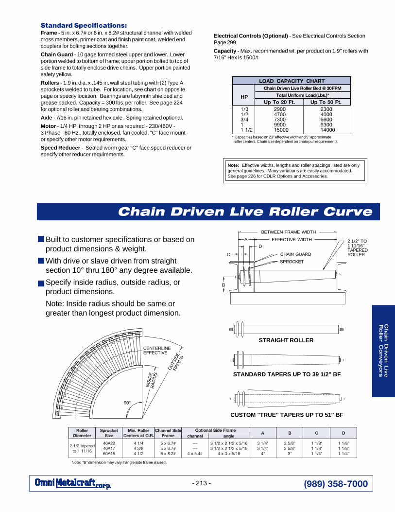
Standard Specifications:Frame - 5 in. x 6.7# or 6 in. x 8.2# structural channel with weldedcross members, primer coat and finish paint coat, welded endcouplers for bolting sections together.
Chain Guard - 10 gage formed steel upper and lower. Lowerportion welded to bottom of frame; upper portion bolted to top ofside frame to totally enclose drive chains. Upper portion paintedsafety yellow.
Rollers - 1.9 in. dia. x .145 in. wall steel tubing with (2) Type Asprockets welded to tube. For location, see chart on oppositepage or specify location. Bearings are labyrinth shielded andgrease packed. Capacity = 300 lbs. per roller. See page 224for optional roller and bearing combinations.
Axle - 7/16 in. pin retained hex axle. Spring retained optional.
Motor - 1/4 HP through 2 HP or as required - 230/460V -3 Phase - 60 Hz., totally enclosed, fan cooled, “C” face mount -or specify other motor requirements.
Speed Reducer - Sealed worm gear "C" face speed reducer orspecify other reducer requirements.
Note: Effective widths, lengths and roller spacings listed are onlygeneral guidelines. Many variations are easily accommodated.See page 226 for CDLR Options and Accessories.
Built to customer specifications or based onproduct dimensions & weight.
With drive or slave driven from straightsection 10° thru 180° any degree available.
Specify inside radius, outside radius, orproduct dimensions.
Note: Inside radius should be same orgreater than longest product dimension.
* Capacities based on 23" effective width and 5" approximate roller centers. Chain size dependent on chain pull requirements.
HPUp To 20 Ft. Up To 50 Ft.
1/3 2900 23001/2 4700 40003/4 7300 66001 9900 93001 1/2 15000 14000
Chain Driven Live Roller Bed @ 30 FPM
Total Uniform Load (Lbs.)*
LOAD CAPACITY CHART
Chain Driven Live Roller Curve
STRAIGHT ROLLER
STANDARD TAPERS UP TO 39 1/2" BF
CUSTOM "TRUE'' TAPERS UP TO 51'' BF
INS
IDE
RA
DIU
S
90°
CENTERLINEEFFECTIVE
BETWEEN FRAME WIDTH
EFFECTIVE WIDTH
CHAIN GUARD
SPROCKET
A
D
C
2 1/2" TO1 11/16"TAPEREDROLLER
B
Note: “B” dimension may vary if angle side frame is used.
Electrical Controls (Optional) - See Electrical Controls SectionPage 299
Capacity - Max. recommended wt. per product on 1.9" rollers with7/16" Hex is 1500#
■■■■■
■■■■■
■■■■■
relloRretemaiD
tekcorpSeziS
relloR.niM.R.OtasretneC
ediSlennahCemarF
emarFediSlanoitpOA B C D
lennahc elgna
derepat2/1261/111ot
22A0471A0451A06
4/148/342/14
#7.6x5#7.6x5#2.8x6
------
#4.5x4
61/5x2/12x2/1361/5x2/12x2/13
61/5x3x4
"4/13"4/13
"4
"8/52"8/52
"3
"8/11"8/11"4/11
"8/11"8/11"4/11
OU
TSID
ER
ADIU
S
(989) 358-7000
Cha
in D
rive
n L
ive
Ro
ller
Co
nve
yo
rs
- 214 -
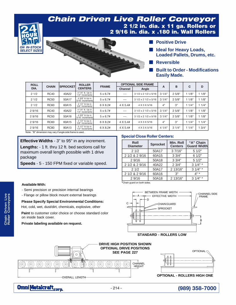
Chain Driven Live Roller Conveyor2 1/2 in. dia. x 11 ga. Rollers or
2 9/16 in. dia. x .180 in. Wall Rollers
Note: “B” dimension may vary if angle side frame is used.
OVERALL LENGTH
CHANNELHEIGHT
DRIVE HIGH POSITION SHOWNOPTIONAL DRIVE POSITIONS
SEE PAGE 227
OPTIONAL - ROLLERS HIGH ONE
OPTIONAL
LLOR.AID
NIAHC TEKCORPSRELLORSRETNEC
EMARFEMARFEDISLANOITPO
A B C DlennahC elgnA
2/12 04CR 22A04 nipU&"4/14stnemercni"4/1 #7.6x5 --- 61/5x2/12x2/13 "4/13 "8/52 "8/11 "8/11
2/12 05CR 71A05 nipU&"8/34stnemercnI"61/5 #7.6x5 --- 61/5x2/12x2/13 "4/13 "8/52 "8/11 "8/11
2/12 06CR 51A06 nipU&"2/14stnemercnI"8/3 #2.8X6 #4.5X4 61/5X3X4 "4 "3 "4/11 "4/11
61/92 04CR 22A04 nipU&"4/14stnemercni"4/1 #7.6x5 --- 61/5x2/12x2/13 "4/13 "8/52 "8/11 "8/11
61/92 05CR 81A05 nipU&"8/34stnemercnI"61/5 #7.6x5 --- 61/5x2/12x2/13 "4/13 "8/52 "8/11 "8/11
61/92 06CR 51A06 nipU&"2/14stnemercnI"8/3 #2.8X6 #4.5X4 61/5X3X4 "4 "3 "4/11 "4/11
61/92 08CR 31A08 nipU&"2/15stnemercnI"2/1 #2.8X6 #4.5X4 61/5X3X4 "4/14 "4/13 "4/11 "4/31
STANDARD - ROLLERS LOW
EFFECTIVE WIDTHCHANNEL SIDEFRAMEA
D
SPROCKET
CHAIN GUARD
B
BETWEEN FRAME WIDTH
Effective Widths - 3" to 95" in any increment.
Lengths: - 1 ft. thru 12 ft. bed sections call formaximum overall length possible with 1 drivepackage
Speeds - 5 - 150 FPM fixed or variable speed.
■■■■■ Positive Drive
■■■■■ Ideal for Heavy Loads,Loaded Pallets, Drums, etc.
■■■■■ Reversible
■■■■■ Built to Order - ModificationsEasily Made.
ON IN-STOCK SELECT SIZES
lloRretemaiD tekcorpS lloR.niM
sretneCniahC”A“
htdiWdrauG2/12 71A05 "61/73 "2/15
61/92&2/12 51A06 "4/33 "2/1661/92 81A05 "4/33 "2/15
61/92&2/12 22A04 "4/32 *"4/132/12 71A05 "61/312 *"4/13
61/92&2/12 61A06 "3 *"461/92 81A05 "61/312 *"4/13
*Chain guard on both sides.
Special Close Roller Centers:
C
Available With:
- Semi precision or precision internal bearings
- Flange or pillow block mount external bearings
Please Specify Special Environmental Conditions:
Hot, cold, wet, dust/dirt, chemicals, explosive, other
Paint to customer color choice or choose standard coloron inside back cover.
Private labeling available on request.
(989) 358-7000
Cha
in D
rive
n L
ive
Ro
ller C
on
ve
yo
rs
- 215 -
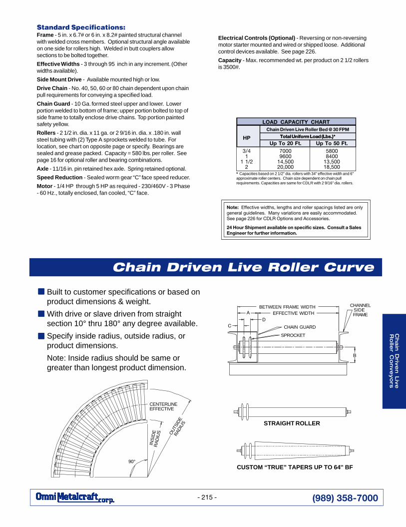
Electrical Controls (Optional) - Reversing or non-reversingmotor starter mounted and wired or shipped loose. Additionalcontrol devices available. See page 226.
Capacity - Max. recommended wt. per product on 2 1/2 rollersis 3500#.
Standard Specifications:Frame - 5 in. x 6.7# or 6 in. x 8.2# painted structural channelwith welded cross members. Optional structural angle availableon one side for rollers high. Welded in butt couplers allowsections to be bolted together.
Effective Widths - 3 through 95 inch in any increment. (Otherwidths available).
Side Mount Drive - Available mounted high or low.
Drive Chain - No. 40, 50, 60 or 80 chain dependent upon chainpull requirements for conveying a specified load.
Chain Guard - 10 Ga. formed steel upper and lower. Lowerportion welded to bottom of frame; upper portion bolted to top ofside frame to totally enclose drive chains. Top portion paintedsafety yellow.
Rollers - 2 1/2 in. dia. x 11 ga. or 2 9/16 in. dia. x .180 in. wallsteel tubing with (2) Type A sprockets welded to tube. Forlocation, see chart on opposite page or specify. Bearings aresealed and grease packed. Capacity = 580 lbs. per roller. Seepage 16 for optional roller and bearing combinations.
Axle - 11/16 in. pin retained hex axle. Spring retained optional.
Speed Reduction - Sealed worm gear “C” face speed reducer.
Motor - 1/4 HP through 5 HP as required - 230/460V - 3 Phase- 60 Hz., totally enclosed, fan cooled, “C” face.
Note: Effective widths, lengths and roller spacings listed are onlygeneral guidelines. Many variations are easily accommodated.See page 226 for CDLR Options and Accessories.
24 Hour Shipment available on specific sizes. Consult a SalesEngineer for further information.
* Capacities based on 2 1/2" dia. rollers with 34" effective width and 6"approximate roller centers. Chain size dependent on chain pullrequirements. Capacities are same for CDLR with 2 9/16" dia. rollers.
HPUp To 20 Ft. Up To 50 Ft.
3/4 7000 58001 9600 8400
1 1/2 14,500 13,5002 20,000 18,500
Chain Driven Live Roller Bed @ 30 FPM
Total Uniform Load (Lbs.)*
LOAD CAPACITY CHART
Total Uniform Load (Lbs.)*
CUSTOM “TRUE” TAPERS UP TO 64'' BF
Built to customer specifications or based onproduct dimensions & weight.
With drive or slave driven from straightsection 10° thru 180° any degree available.
Specify inside radius, outside radius, orproduct dimensions.
Note: Inside radius should be same orgreater than longest product dimension.
Chain Driven Live Roller Curve
■■■■■
■■■■■
■■■■■
STRAIGHT ROLLER
EFFECTIVE WIDTH
CHAIN GUARD
SPROCKET
A
DC
B
CHANNELSIDE FRAME
BETWEEN FRAME WIDTH
CENTERLINEEFFECTIVE
90°
OU
TSID
ER
ADIU
S
INS
IDE
RA
DIU
S

(989) 358-7000
Cha
in D
rive
n L
ive
Ro
ller
Co
nve
yo
rs
- 216 -
Chain Driven Live Roller Conveyor3 1/2 in. dia. x .300 in. Wall Rollers
OVERALL LENGTH
CHANNELHEIGHT
DRIVE HIGH POSITION SHOWNOPTIONAL DRIVE POSITIONS SEE PAGE 227
STANDARD - ROLLERS LOW
EFFECTIVE WIDTH
D
CHAIN GUARD
SPROCKET
A
C
B
CHANNELSIDE FRAME
BETWEEN FRAME WIDTH
OPTIONAL - ROLLERS HIGH ONE SIDE
OPTIONALSIDE FRAME
Effective Widths - 3" to 120" in any Increment.Lengths: - 1 ft. thru 12 ft. bed sections call formaximum overall length possible with 1 drivepackageSpeeds - 5 - 150 FPM fixed or variable speed.
■ Positive Drive
■ Ideal for Heavy Loads,Loaded Pallets, Drums, etc.
■ Reversible
■ Built to Order - ModificationsEasily Made.
*Chain guard on both sides
Special Close Roller Centers:lloR
retemaiD tekcorpS lloR.niMsretneC
niahC”A“htdiWdrauG
2/13 02A06 "8/74 "2/162/13 61A08 "5 "4/372/13 02A06 "4/33 *"42/13 61A08 "4/33 *"4/14
LLOR.AID
NIAHC TEKCORPSRELLORSRETNEC
EMARFEMARFEDISLANOITPO
A B C DlennahC elgnA
2/13 06CR 02A06 "8/3nipu&"6stnemercni #8.9x7 #7.6x5 61/5x3x5 "4 "2/13 "4/11 "4/11
2/13 08CR 61A08 nipu&"2/16stnemercni"2/1 #5.11x8 #2.8x6 8/3x4x6 "4/14 "2/14 "4/11 "4/31
2/13 001CR 31A001 nipu&"8/76stnemercni"8/5 #5.11x8 #2.8x6 8/3x4x6 "5 "2/14 "8/31 "2
Available With:
- Semi precision or precision internal bearings
- Flange or pillow block mount external bearings
Please Specify Special Environmental Conditions:
Hot, cold, wet, dust/dirt, chemicals, explosive, other
Paint to customer color choice or choose standard coloron inside back cover.
Private labeling available on request.
(989) 358-7000
Cha
in D
rive
n L
ive
Ro
ller C
on
ve
yo
rs
- 217 -
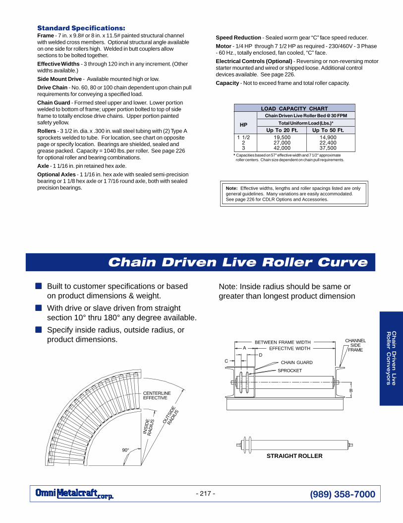
Standard Specifications:Frame - 7 in. x 9.8# or 8 in. x 11.5# painted structural channelwith welded cross members. Optional structural angle availableon one side for rollers high. Welded in butt couplers allowsections to be bolted together.
Effective Widths - 3 through 120 inch in any increment. (Otherwidths available.)
Side Mount Drive - Available mounted high or low.
Drive Chain - No. 60, 80 or 100 chain dependent upon chain pullrequirements for conveying a specified load.
Chain Guard - Formed steel upper and lower. Lower portionwelded to bottom of frame; upper portion bolted to top of sideframe to totally enclose drive chains. Upper portion paintedsafety yellow.
Rollers - 3 1/2 in. dia. x .300 in. wall steel tubing with (2) Type Asprockets welded to tube. For location, see chart on oppositepage or specify location. Bearings are shielded, sealed andgrease packed. Capacity = 1040 lbs. per roller. See page 226for optional roller and bearing combinations.
Axle - 1 1/16 in. pin retained hex axle.
Optional Axles - 1 1/16 in. hex axle with sealed semi-precisionbearing or 1 1/8 hex axle or 1 7/16 round axle, both with sealedprecision bearings.
Speed Reduction - Sealed worm gear “C” face speed reducer.
Motor - 1/4 HP through 7 1/2 HP as required - 230/460V - 3 Phase- 60 Hz., totally enclosed, fan cooled, “C” face.
Electrical Controls (Optional) - Reversing or non-reversing motorstarter mounted and wired or shipped loose. Additional controldevices available. See page 226.
Capacity - Not to exceed frame and total roller capacity.
* Capacities based on 57" effective width and 7 1/2" approximate roller centers. Chain size dependent on chain pull requirements.
Note: Effective widths, lengths and roller spacings listed are onlygeneral guidelines. Many variations are easily accommodated.See page 226 for CDLR Options and Accessories.
HPUp To 20 Ft. Up To 50 Ft.
1 1/2 19,500 14,9002 27,000 22,4003 42,000 37,500
Chain Driven Live Roller Bed @ 30 FPM
Total Uniform Load (Lbs.)*
LOAD CAPACITY CHART
STRAIGHT ROLLER
■■■■■ Built to customer specifications or basedon product dimensions & weight.
■■■■■ With drive or slave driven from straightsection 10° thru 180° any degree available.
■■■■■ Specify inside radius, outside radius, orproduct dimensions.
Chain Driven Live Roller Curve
EFFECTIVE WIDTH
B
CHANNELSIDE
FRAMED
A
C CHAIN GUARD
SPROCKET
BETWEEN FRAME WIDTH
Note: Inside radius should be same orgreater than longest product dimension
CENTERLINEEFFECTIVE
90°
OU
TSID
ER
ADIU
S
INS
IDE
RA
DIU
S

(989) 358-7000
Cha
in D
rive
n L
ive
Ro
ller
Co
nve
yo
rs
- 218 -
Chain Driven Live Roller Conveyor4 in. dia. x 1/2 in. Wall Rollers or
5 in. dia. x 3/4 in. Wall Rollers
■■■■■ Side mount drive
■■■■■ Reversible
■■■■■ Ideal for heavy loads,loaded pallets, drums, etc.
■■■■■ 5 in. to 120 in. effective widths
OVERALL LENGTH
CHANNELHEIGHT
Effective Widths - 5" to 120" in any increment.Lengths: - 1 ft. thru 12 ft. bed sections call formaximum overall length possible with 1 drivepackageSpeeds - 5 - 150 FPM fixed or variable speed.
Special Close Roller Centers:
OPTIONAL - ROLLERS HIGH ONE SIDE
OPTIONALSIDE FRAME
E
STANDARD - ROLLERS LOW
EFFECTIVE WIDTH
CHAIN GUARD
A
C
SPROCKET
CHANNEL SIDEFRAME
B
D
BETWEEN FRAME WIDTH
LLOR.AID
NIAHC TEKCORPSRELLORSRETNEC
EMARFEMARFEDISLANOITPO
A B C DlennahC elgnA
4 06CR 22A06 nipudna"8/36stnemercni"8/3 #8.9x7 #7.6x5 61/5x3x5 4 2/13 4/11 4/11
4 08CR 71A08 nipudna"7stnemercni"2/1 #5.11X8 #2.8x6 2/1x4x6 4/14 2/14 4/11 4/31
4 001CR 41A001 nipudna"2/17stnemercni"8/5 #5.11X8 #2.8x6 2/1x4x6 5 2/14 8/31 2
5 08CR 02A08 nipudna"8stnemercni"2/1 #3.51X01 #8.9x7 2/1x4x7 4/14 2/15 4/11 4/31
5 001CR 71A001 nipudna"4/38stnemercni"8/5 #3.51X01 #8.9x7 2/1x4x7 5 2/15 8/31 2
lloRretemaiD tekcorpS lloR.niM
sretneCniahC”A“
htdiWdrauG4 22A06 4/15 2/16
4 71A08 2/15 4/37
4 41A001 8/55 9
5 02A08 2/16 4/37
5 71A001 8/76 9
DRIVE HIGH POSITIONSHOWN OPTIONAL DRIVEPOSITIONS SEE PAGE 227
Available With:
- Semi precision or precision internal bearings
- Flange or pillow block mount external bearings
Please Specify Special Environmental Conditions:
Hot, cold, wet, dust/dirt, chemicals, explosive, other
Paint to customer color choice or choose standard coloron inside back cover.
Private labeling available on request.
(989) 358-7000
Cha
in D
rive
n L
ive
Ro
ller C
on
ve
yo
rs
- 219 -
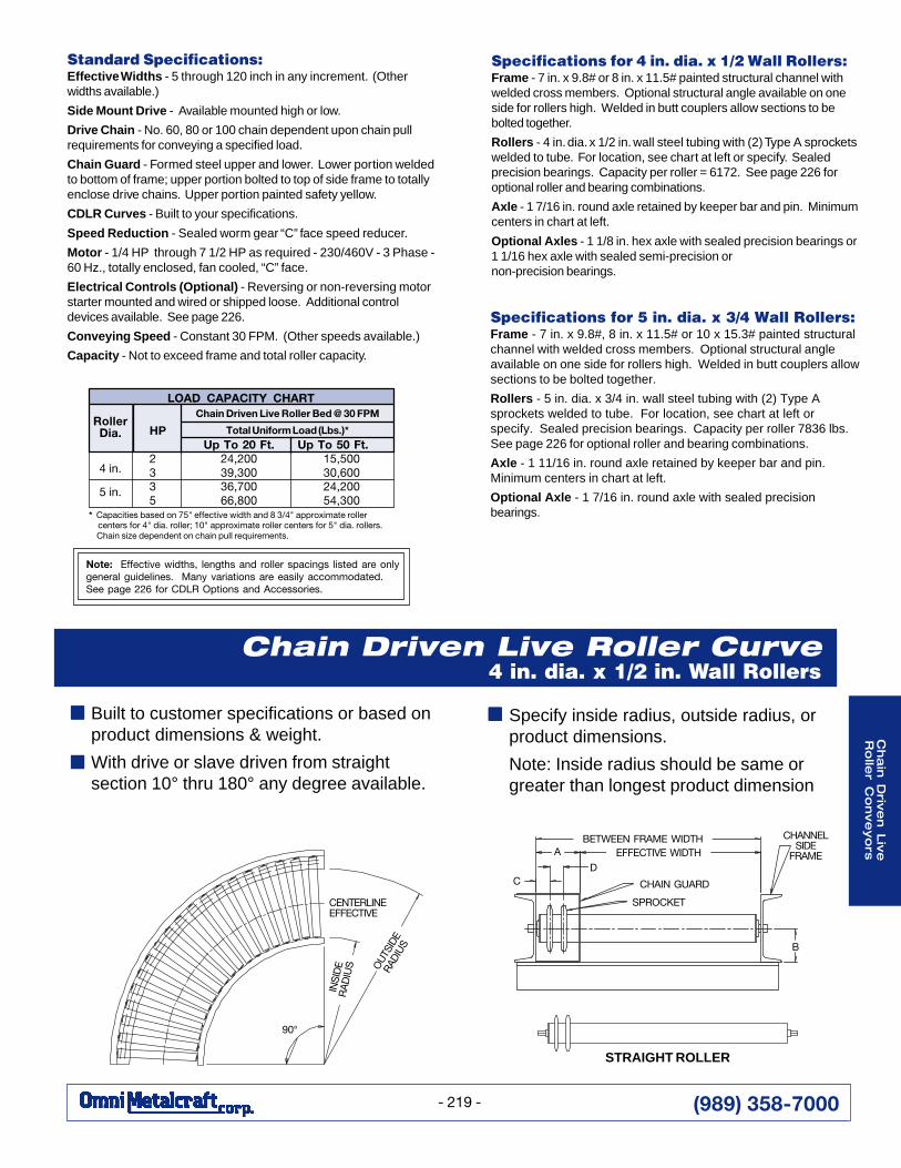
Standard Specifications:Effective Widths - 5 through 120 inch in any increment. (Otherwidths available.)
Side Mount Drive - Available mounted high or low.
Drive Chain - No. 60, 80 or 100 chain dependent upon chain pullrequirements for conveying a specified load.
Chain Guard - Formed steel upper and lower. Lower portion weldedto bottom of frame; upper portion bolted to top of side frame to totallyenclose drive chains. Upper portion painted safety yellow.
CDLR Curves - Built to your specifications.
Speed Reduction - Sealed worm gear “C” face speed reducer.
Motor - 1/4 HP through 7 1/2 HP as required - 230/460V - 3 Phase -60 Hz., totally enclosed, fan cooled, “C” face.
Electrical Controls (Optional) - Reversing or non-reversing motorstarter mounted and wired or shipped loose. Additional controldevices available. See page 226.
Conveying Speed - Constant 30 FPM. (Other speeds available.)
Capacity - Not to exceed frame and total roller capacity.
Note: Effective widths, lengths and roller spacings listed are onlygeneral guidelines. Many variations are easily accommodated.See page 226 for CDLR Options and Accessories.
STRAIGHT ROLLER
Built to customer specifications or based onproduct dimensions & weight.
With drive or slave driven from straightsection 10° thru 180° any degree available.
Chain Driven Live Roller Curve4 in. dia. x 1/2 in. Wall Rollers
EFFECTIVE WIDTH
B
CHANNELSIDE
FRAMED
A
C CHAIN GUARD
SPROCKET
BETWEEN FRAME WIDTH
■■■■■
■■■■■
Specify inside radius, outside radius, orproduct dimensions.
Note: Inside radius should be same orgreater than longest product dimension
CENTERLINEEFFECTIVE
90°
OUT
SIDE
RADI
US
INS
IDE
RA
DIU
S
Specifications for 4 in. dia. x 1/2 Wall Rollers:Frame - 7 in. x 9.8# or 8 in. x 11.5# painted structural channel withwelded cross members. Optional structural angle available on oneside for rollers high. Welded in butt couplers allow sections to bebolted together.
Rollers - 4 in. dia. x 1/2 in. wall steel tubing with (2) Type A sprocketswelded to tube. For location, see chart at left or specify. Sealedprecision bearings. Capacity per roller = 6172. See page 226 foroptional roller and bearing combinations.
Axle - 1 7/16 in. round axle retained by keeper bar and pin. Minimumcenters in chart at left.
Optional Axles - 1 1/8 in. hex axle with sealed precision bearings or1 1/16 hex axle with sealed semi-precision ornon-precision bearings.
* Capacities based on 75" effective width and 8 3/4" approximate roller centers for 4" dia. roller; 10" approximate roller centers for 5" dia. rollers. Chain size dependent on chain pull requirements.
HPUp To 20 Ft. Up To 50 Ft.
2 24,200 15,5003 39,300 30,6003 36,700 24,2005 66,800 54,300
RollerDia.
4 in.
5 in.
Total Uniform Load (Lbs.)*
Chain Driven Live Roller Bed @ 30 FPMLOAD CAPACITY CHART
Specifications for 5 in. dia. x 3/4 Wall Rollers:Frame - 7 in. x 9.8#, 8 in. x 11.5# or 10 x 15.3# painted structuralchannel with welded cross members. Optional structural angleavailable on one side for rollers high. Welded in butt couplers allowsections to be bolted together.
Rollers - 5 in. dia. x 3/4 in. wall steel tubing with (2) Type Asprockets welded to tube. For location, see chart at left orspecify. Sealed precision bearings. Capacity per roller 7836 lbs.See page 226 for optional roller and bearing combinations.
Axle - 1 11/16 in. round axle retained by keeper bar and pin.Minimum centers in chart at left.
Optional Axle - 1 7/16 in. round axle with sealed precisionbearings.
■■■■■

(989) 358-7000
Cha
in D
rive
n L
ive
Ro
ller
Co
nve
yo
rs
- 220 -
Zero Pressure CDLR Conveyor(Zero Pressure Accumulation)
1.9 in. dia. x .145 in. Wall Rollers
Standard Specifications:Frame - 6 in. x 8.2# painted structural channel with welded crossmembers. Welded in butt couplers allow sections to be boltedtogether.
Effective Widths - 13 through 39 inch in any increment. (Otherwidths available.)
Drive Chain - No. 40 chain roll to roll. No. 60 chain zone to zone.
Chain Guard - Formed steel upper and lower. Lower portionwelded to bottom of frame; upper portion bolted to top of side frameto totally enclose drive chains. Upper portion painted safety yellow.
Rollers - 1.9 in. dia. x .145 wall steel tubing with (2) 40A18sprockets welded to tube. Bearings are sealed and greasepacked. Capacity = 300 lbs. per roller. See page 226 for optionalroller and bearing combinations.
Axle - 7/16 in. pin retained hex axle. Available with 3 in., 4 1/2 in.and 6 in. axle centers.
Drive - Sealed worm gear “C” face speed reducer with230/460 V - 60 Hz - 3 phase motor. Totally enclosed fancooled. Other specifications available. Mounted side high.
Clutches - Conveyor zones are controlled by pneumatic frictiondisk type clutches (not tooth type clutches) for a smoother start.Air pressure can be regulated to adjust smoothness of start.
Conveying Speed - Constant 30 FPM. (Other speeds available.)
■■■■■ Zero back pressure reduces possibilityof product damage
■■■■■ 1500 lbs. per zone
■■■■■ Multiple zones driven from single drive
■■■■■ Each zone powered througha pneumatic clutch
Note: Effective widths, lengths and roller spacings listed are onlygeneral guidelines. Many variations are easily accommodated.See page 226 for CDLR Options and Accessories.
Electrical Controls (Standard) - 115 VAC - single phase - 60 Hz.solenoid valve in discharge zone to override sensor roller. Limitswitch is also supplied to revert control back to the sensor rolleronce the product is clear.
Capacity - Max. load capacity per zone is 1500 lbs. Max. loadcapacity per roller is 300 lbs. Note: Drive is sized to power 50% ofzones loaded simultaneously. HP required for given lengthsare shown below.
llarevOhtgneL
htdiWevitceffE "31 "51 "71 "91 "12 "32 "52 "72 "03 "33 "63 "93
htdiWemarFneewteB "4/161 "4/181 "4/102 "4/122 "4/142 "4/162 "4/182 "4/103 "4/133 "4/163 "4/193 "4/124
'5'01
sthgieW).sbl(
sthgieWnodesaB
relloR.ag541.x.aid"9.1sretneCrelloR"6
stekcorpS81A04dna
673046
483456
193766
793386
304596
014907
714227
424537
434657
444777
554797
564718
'51'02
4098611
4294911
3499121
9695521
7899721
80017031
72012331
64017531
87010041
01113441
93111841
96111251
'52'03
23416961
46414371
59411771
14517281
17513681
60615091
73612491
86619791
22714402
67719012
32815612
37815222
'04'05
42222572
47224182
32325782
99321792
74421303
30521013
25522613
10623223
88622333
57721443
94823353
92923363
'06'07
08238083
45334983
72439793
34535114
51639914
99637924
27732834
54837644
67930264
70143774
71241094
73341405
'08'09
63344684
43444794
13543805
78649525
38747635
59843945
29942065
98051175
46258095
93455016
58559626
54759446
'001 2935 4155 5365 1385 1595 1906 2126 3336 2556 1776 3596 3517
)EVIL(TRAHCYTICAPACDAOL
PHMPF03@relloReviLnevirDniahC
*).sbl(daoLmrofinUlatoT.tf05oTpU .tf001oTpU
4/31
2/112
005600590055100512
005400070003100091
evitceffe"32htiwsrellor.aid"9.1nodesabseiticapaC*ezisniahC.sretnecrelloretamixorppa"2/14dnahtdiw
.stnemeriuqerllupniahcnotnedneped
rehtOrelloRsretneC
noitceS.tf01rePthgieWddA
htdiWevitceffE "31 "51 "71 "91 "12 "32 "52 "72 "03 "33 "63 "93
"3"2/14
).sbl(thgieWddA).sbl(thgieWddA
8734
0905
20165
31126
52196
73157
94128
16198
97189
791801
512811
332821
.derisedgnicapsrellornognidnepedylthgilsegnahcyamroyevnocfohtgnelllarevO:etoN)senozL"06nodesabsthgieW(
(989) 358-7000
Cha
in D
rive
n L
ive
Ro
ller C
on
ve
yo
rs
- 221 -
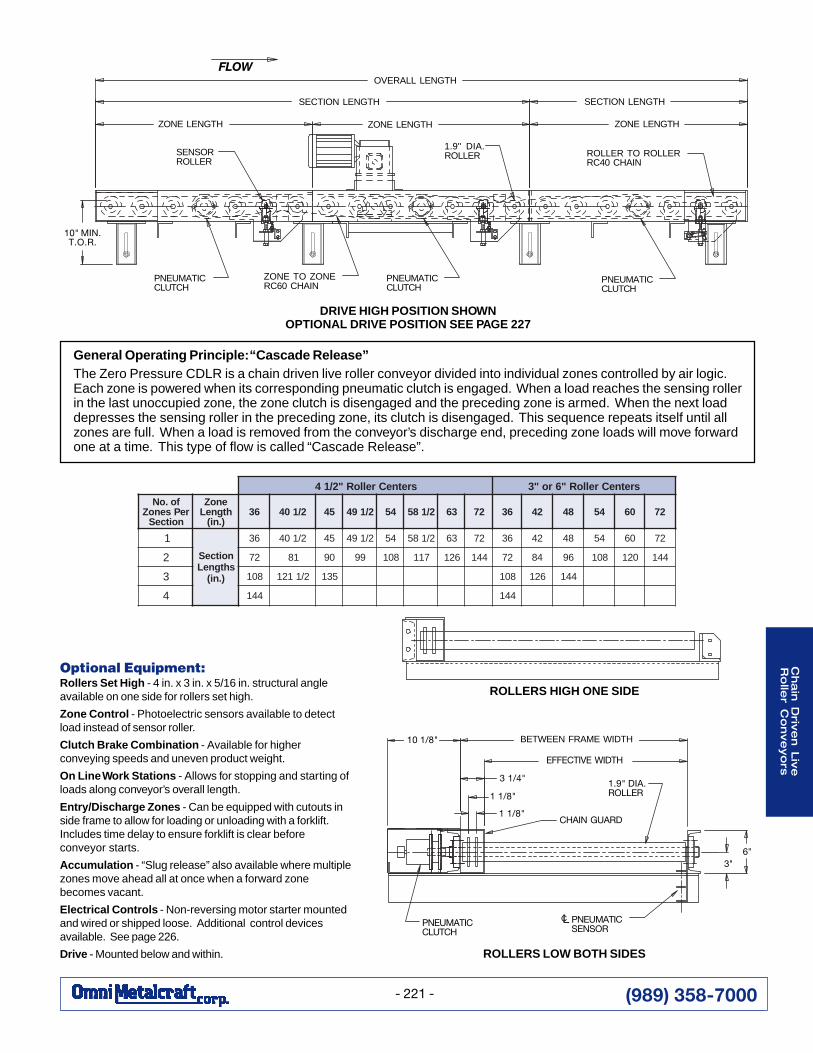
General Operating Principle: “Cascade Release”The Zero Pressure CDLR is a chain driven live roller conveyor divided into individual zones controlled by air logic.Each zone is powered when its corresponding pneumatic clutch is engaged. When a load reaches the sensing rollerin the last unoccupied zone, the zone clutch is disengaged and the preceding zone is armed. When the next loaddepresses the sensing roller in the preceding zone, its clutch is disengaged. This sequence repeats itself until allzones are full. When a load is removed from the conveyor’s discharge end, preceding zone loads will move forwardone at a time. This type of flow is called “Cascade Release”.
Optional Equipment:Rollers Set High - 4 in. x 3 in. x 5/16 in. structural angleavailable on one side for rollers set high.
Zone Control - Photoelectric sensors available to detectload instead of sensor roller.
Clutch Brake Combination - Available for higherconveying speeds and uneven product weight.
On Line Work Stations - Allows for stopping and starting ofloads along conveyor’s overall length.
Entry/Discharge Zones - Can be equipped with cutouts inside frame to allow for loading or unloading with a forklift.Includes time delay to ensure forklift is clear beforeconveyor starts.
Accumulation - “Slug release” also available where multiplezones move ahead all at once when a forward zonebecomes vacant.
Electrical Controls - Non-reversing motor starter mountedand wired or shipped loose. Additional control devicesavailable. See page 226.
Drive - Mounted below and within.
sretneCrelloR"2/14 sretneCrelloR"6ro"3fo.oN
rePsenoZnoitceS
enoZhtgneL
).ni(63 2/104 54 2/194 45 2/185 36 27 63 24 84 45 06 27
1
noitceSshtgneL
).ni(
63 2/104 54 2/194 45 2/185 36 27 63 24 84 45 06 27
2 27 18 09 99 801 711 621 441 27 48 69 801 021 441
3 801 2/1121 531 801 621 441
4 441 441
OVERALL LENGTH
SECTION LENGTH
ZONE LENGTH
1.9" DIA.ROLLERSENSOR
ROLLER
ZONE LENGTH
PNEUMATICCLUTCH
ZONE TO ZONERC60 CHAIN
PNEUMATICCLUTCH
PNEUMATICCLUTCH
ROLLER TO ROLLERRC40 CHAIN
SECTION LENGTH
FLOW
ZONE LENGTH
EFFECTIVE WIDTH
PNEUMATICSENSOR
PNEUMATICCLUTCH
BETWEEN FRAME WIDTH
1.9" DIA.ROLLER
CHAIN GUARD
ROLLERS LOW BOTH SIDES
10 1/8"
3 1/4"
1 1/8"
1 1/8"
6"3"
CL
10" MIN.T.O.R.
DRIVE HIGH POSITION SHOWNOPTIONAL DRIVE POSITION SEE PAGE 227
ROLLERS HIGH ONE SIDE

(989) 358-7000
Cha
in D
rive
n L
ive
Ro
ller
Co
nve
yo
rs
- 222 -
Zero Pressure CDLR Conveyor(Zero Pressure Accumulation)
2 1/2 in. dia. x 11 ga. Rollers or2 9/16 in. dia. x .180 in. Wall Rollers
Electrical Controls (Standard) - 115 VAC - single phase - 60 Hz.solenoid valve in discharge zone to override sensor roller. Limitswitch is also supplied to revert control back to the sensor roller oncethe product is clear.
Capacity - Max. load capacity per zone is 3500 lbs. Max. loadcapacity per roller is 580 lbs. Note: Drive is sized to power 50%of zones loaded simultaneously. HP required for given lengths areshown below.
Standard Specifications:Frame - 6 in. x 8.2# painted structural channel with welded crossmembers. Welded-in butt couplers allow sections to be boltedtogether.
Effective Widths - 16 through 60 inch in any increment. (Otherwidths available.)
Drive Chain - No. 40 chain roll to roll. No. 60 chain zone to zone.
Chain Guard - Formed steel upper and lower. Lower portionwelded to bottom of frame; upper portion bolted to top of sideframe to totally enclose drive chains. Upper portion painted safetyyellow.
Rollers - 2 1/2 in. dia. x 11 ga. or 2 9/16 in. dia. x .180 wallsteel tubing with (2) 40A22 sprockets welded to tube. Bearingsare sealed and grease packed. Capacity = 580 lbs. per roller.See page 16 for optional roller and bearing combinations.
Axle - 11/16 in. pin retained hex axle. Available with 3 in., 4 1/2 in.and 6 in. axle centers.
Drive - Sealed worm gear “C” face speed reducer with 230/460 V- 60 Hz - 3 phase motor. Totally enclosed fan cooled. Otherspecifications available. Mounted side high.
Clutches - Conveyor zones are controlled by pneumatic frictiondisk type clutches (not tooth type clutches) for a smoother start.Air pressure can be regulated to adjust smoothness of start.
Conveying Speed - Constant 30 FPM. (Other speeds available.)
Note: Effective widths, lengths and roller spacings listed are onlygeneral guidelines. Many variations are easily accommodated.See page 226 for CDLR Options and Accessories.
llarevOhtgneL
htdiWevitceffE "61 "02 "42 "82 "23 "63 "04 "44 "84 "25 "65 "06
htdiWemarFneewteB "4/191 "4/132 "4/172 "4/113 "4/153 "4/193 "4/134 "4/174 "4/115 "4/155 "4/195 "4/136
'5'01
sthgieW).sbl(
sthgieWnodesaB
relloR.ag11x.aid"2/12sretneCrelloR"6
stekcorpS22A04dnasenoz'5
844387
464718
184158
894488
515819
235159
845589
5659101
2852501
9956801
6169111
2363511
'51'02
91115541
96112251
02219851
07216561
12313271
17311971
12418581
27415291
22512991
37519502
32617212
37614912
'52'03
09710312
67810322
06910332
24028242
72120352
80227262
69223372
08324382
26422392
74524303
82622313
61727323
'04'05
00820743
53921463
07031183
00230793
63330414
56433034
70631844
04736464
27832184
80042894
73143415
97241235
'06'07
04145184
74343505
05540925
04740155
84940575
04159795
55359226
25558546
25752966
65950396
94165517
36365047
'08'09
58459516
95755646
03060776
08260507
06560637
71865567
30175797
46370728
23672758
40978788
16187619
74489849
'001 0386 0717 0157 0287 0718 0948 0588 5719 2159 2589 37101 13501
rehtOrelloRsretneC
noitceS.tf01repthgieWddA
htdiWevitceffE "61 "02 "42 "82 "23 "63 "04 "44 "84 "25 "65 "06
"3"2/14
).sbl(thgieWddA).sbl(thgieWddA
44197
37188
30299
232901
262911
292031
123041
153151
083161
014171
044281
964291
.derisedgnicapsrellornognidnepedylthgilsegnahcyamroyevnocfohtgnelllarevO:etoN)senozL"06nodesabsthgieW(
)EVIL(TRAHCYTICAPACDAOL
PHMPF03@relloReviLnevirDniahC
*).sbl(daoLmrofinUlatoT.tf05oTpU .tf001oTpU
4/31
2/112
000600090005100012
057300560052100581
evitceffe"43htiwsrellor.aid"2/12nodesabseiticapaC*ezisniahC.sretnecrelloretamixorppa"2/14dnahtdiw
eraseiticapaC.stnemeriuqerllupniahcnotnedneped.srellor.aid"61/92htiwRLDCrofemas
■■■■■ Multiple zones driven from single drive
■■■■■ Each zone powered through a pneumatic clutch
■■■■■ Zero back pressure reduces possibility of product damage
■■■■■ 3500 lbs. per zone

(989) 358-7000
Cha
in D
rive
n L
ive
Ro
ller C
on
ve
yo
rs
- 223 -
General Operating Principle: “Cascade Release”The Zero Pressure CDLR is a chain driven live roller conveyor divided into individual zones controlled by air logic.Each zone is powered when its corresponding pneumatic clutch is engaged. When a load reaches the sensingroller in the last unoccupied zone, the zone clutch is disengaged and the preceding zone is armed. When the nextload depresses the sensing roller in the preceding zone, its clutch is disengaged. This sequence repeats itself untilall zones are full. When a load is removed from the conveyor’s discharge end, preceding zone loads will moveforward one at a time. This type of flow is called “Cascade Release”.
Optional Equipment:Rollers Set High - 4 in. x 3 in. x 5/16 in. structural angleavailable on one side for rollers set high.
Zone Control - Photoelectric sensors available to detectload instead of sensor roller.
Clutch Brake Combination - Available for higherconveying speeds and uneven product weight.
On Line Work Stations - Allows for stopping and starting ofloads along overall length of conveyor.
Entry/Discharge Zones - Can be equipped with cutouts inside frame to allow for loading or unloading with a forklift.Includes time delay to ensure forklift is clear beforeconveyor starts.
Accumulation - “Slug release” also available where multiplezones move ahead all at once when a forward zonebecomes vacant.
Electrical Controls - Non-reversing motor starter mountedand wired or shipped loose. Additional control devicesavailable. See page 226.
Drive - Mounted below and within.
ROLLERS HIGH ONE SIDE
DRIVE HIGH POSITION SHOWNOPTIONAL DRIVE POSITION SEE PAGE 227
sretneCrelloR"2/14 sretneCrelloR"6ro"3fo.oN
rePsenoZnoitceS
enoZhtgneL
).ni(63 2/104 54 2/194 45 2/185 36 27 63 24 84 45 06 27
1
noitceSshtgneL
).ni(
63 2/104 54 2/194 45 2/185 36 27 63 24 84 45 06 27
2 27 18 09 99 801 711 621 441 27 48 69 801 021 441
3 801 2/1121 531 801 621 441
4 441 441
OVERALL LENGTH
SECTION LENGTH
2 1/2" DIA.ROLLER
SECTION LENGTH
ZONE LENGTH
ROLLER TO ROLLERRC40 CHAIN
PNEUMATICCLUTCH
ZONE TO ZONERC60 CHAIN
PNEUMATICCLUTCH
10" MIN.T.O.R.
PNEUMATICCLUTCH
ZONE LENGTH
SENSORROLLER
FLOW
ZONE LENGTH
PNEUMATICSENSOR
PNEUMATICCLUTCH
ROLLERS LOW BOTH SIDES
EFFECTIVE WIDTH
CHAIN GUARD1 1/8"
2 1/2" DIA.ROLLER1 1/8"
3 1/4"
10 1/8" BETWEEN FRAME WIDTH
6"3"
LC

(989) 358-7000
Cha
in D
rive
n L
ive
Ro
ller
Co
nve
yo
rs
- 224 -
Zero Pressure CDLR Conveyor(Zero Pressure Accumulation)
3 1/2 in. dia. x .300 in. Wall Rollers
Electrical Controls (Standard) - 115 VAC - single phase - 60 Hz.solenoid valve in discharge zone to override sensor roller. Limitswitch is also supplied to revert control back to the sensor rolleronce the product is clear.
Capacity - Max. load capacity per zone is 6000 lbs. Max. loadcapacity per roller is 1040 lbs. Note: Drive is sized to power 50%of zones loaded simultaneously.
Standard Specifications:Frame - 7 in. x 9.8# painted structural channel with welded crossmembers. Welded-in butt couplers allow sections to be boltedtogether.
Effective Widths - 30 through 84 inch in any increment. (Otherwidths available.)
Drive Chain - No. 60 chain roll to roll. No. 80 chain zone to zone.
Chain Guard - Formed steel upper and lower. Lower portionwelded to bottom of frame; upper portion bolted to top of sideframe to totally enclose drive chains. Upper portion paintedsafety yellow.
Rollers - 3 1/2 in. dia. x .300 wall steel tubing with (2) 60A20sprockets welded to tube. Bearings are sealed and greasepacked. Capacity = 1040 lbs. per roller. See page 226 foroptional roller and bearing combinations.
Axle - 1 1/16 in. pin retained hex axle.
Drive - Sealed worm gear “C” face speed reducer with 230/460 V- 60 Hz - 3 phase motor. Totally enclosed fan cooled. Otherspecifications available. Mounted side high.
Clutches - Conveyor zones are controlled by pneumatic frictiondisk type clutches (not tooth type clutches) for a smoother start.Air pressure can be regulated to adjust smoothness of start.
Conveying Speed - Constant 30 FPM max. (Other speedsavailable.)
■■■■■ Multiple zones driven from single drive
■■■■■ Each zone powered througha pneumatic clutch
■■■■■ Zero back pressure reduces possibilityof product damage
■■■■■ 6000 lbs. per zone
Note: Effective widths, lengths and roller spacings listed are onlygeneral guidelines. Many variations are easily accommodated.See page 226 for CDLR Options and Accessories.
)EVIL(TRAHCYTICAPACDAOL
rehtOrelloRsretneC
MPF03@relloReviLnevirDniahC*).sbl(daoLmrofinUlatoT
.tf02oTpU .tf05oTpU4/3
12/11
2
005500280033100291
05210573052905741
evitceffe"06htiwsrellor.aid"2/13nodesabseiticapaC*ezisniahC.sretnecrelloretamixorppa"6dnahtdiw
.stnemeriuqerllupniahcnotnedneped
llarevOhtgneL
htdiWevitceffE "03 "43 "93 "44 "94 "45 "95 "46 "96 "47 "97 "48
htdiWemarFneewteB "43 "83 "34 "84 "35 "85 "36 "86 "37 "87 "38 "88
'5'01
sthgieW).sbl(
sthgieWnodesaB
relloRllaW003.x.aid"2/13sretneCrelloR"6
stekcorpS02A06dnasenoz'5
1482351
1981361
3595571
51010881
77014002
93119212
20213522
46217732
62312052
09315262
07619813
34716333
'51'02
32224192
17321113
75529533
54720163
13928583
91139014
40335534
09433064
87634584
06835905
80747226
92942256
'52'03
50636924
15831954
16143694
57440435
58742175
99059806
60457546
61759286
03066027
03365657
64775629
51188079
'04'05
87650607
17061557
76561718
07070088
66570249
960894001
955816601
550918211
855901911
5300150521
3032114351
4982108061
'06'07
24484289
130911501
5779997311
0350106221
4721182131
9402190041
3672156841
7053133751
2624141661
5794154471
9738171412
6629125422
'08'09
6021188521
1991117431
3892178541
0993102751
2894163861
9895196971
7696196091
9597158102
6698181312
5199158322
5544239472
8365242882
'001 07931 15941 19161 05471 09681 94991 17112 11422 07632 55842 13503 01023
(989) 358-7000
Cha
in D
rive
n L
ive
Ro
ller C
on
ve
yo
rs
- 225 -
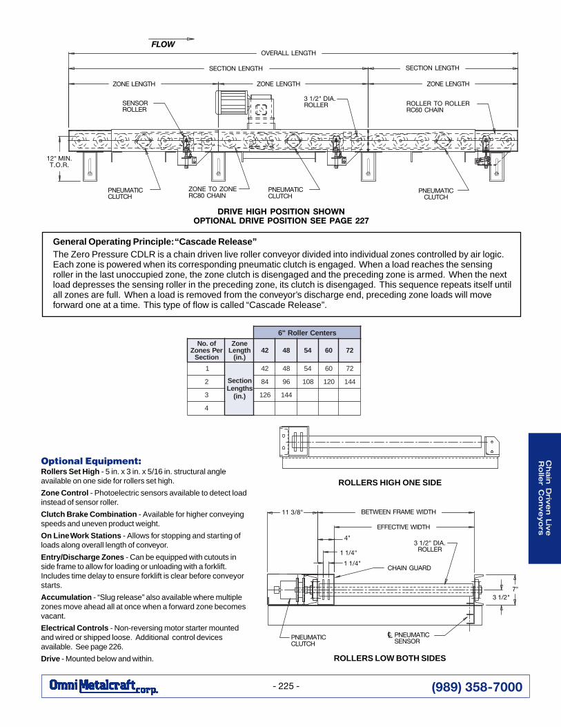
General Operating Principle: “Cascade Release”The Zero Pressure CDLR is a chain driven live roller conveyor divided into individual zones controlled by air logic.Each zone is powered when its corresponding pneumatic clutch is engaged. When a load reaches the sensingroller in the last unoccupied zone, the zone clutch is disengaged and the preceding zone is armed. When the nextload depresses the sensing roller in the preceding zone, its clutch is disengaged. This sequence repeats itself untilall zones are full. When a load is removed from the conveyor’s discharge end, preceding zone loads will moveforward one at a time. This type of flow is called “Cascade Release”.
Optional Equipment:Rollers Set High - 5 in. x 3 in. x 5/16 in. structural angleavailable on one side for rollers set high.
Zone Control - Photoelectric sensors available to detect loadinstead of sensor roller.
Clutch Brake Combination - Available for higher conveyingspeeds and uneven product weight.
On Line Work Stations - Allows for stopping and starting ofloads along overall length of conveyor.
Entry/Discharge Zones - Can be equipped with cutouts inside frame to allow for loading or unloading with a forklift.Includes time delay to ensure forklift is clear before conveyorstarts.
Accumulation - “Slug release” also available where multiplezones move ahead all at once when a forward zone becomesvacant.
Electrical Controls - Non-reversing motor starter mountedand wired or shipped loose. Additional control devicesavailable. See page 226.
Drive - Mounted below and within. ROLLERS LOW BOTH SIDES
sretneCrelloR"6fo.oN
rePsenoZnoitceS
enoZhtgneL
).ni(24 84 45 06 27
1
noitceSshtgneL
).ni(
24 84 45 06 27
2 48 69 801 021 441
3 621 441
4
OVERALL LENGTH
SECTION LENGTH
ZONE LENGTH
3 1/2" DIA.ROLLER
SECTION LENGTH
ZONE LENGTH
ROLLER TO ROLLERRC60 CHAIN
PNEUMATICCLUTCH
PNEUMATICCLUTCH
ZONE TO ZONERC80 CHAIN
PNEUMATICCLUTCH
12" MIN.T.O.R.
ZONE LENGTH
SENSORROLLER
FLOW
DRIVE HIGH POSITION SHOWNOPTIONAL DRIVE POSITION SEE PAGE 227
EFFECTIVE WIDTH
3 1/2" DIA.ROLLER
CHAIN GUARD
PNEUMATICSENSOR
PNEUMATICCLUTCH
3 1/2"
ROLLERS HIGH ONE SIDE
11 3/8"
4"
1 1/4"
1 1/4"
7"
LC
BETWEEN FRAME WIDTH
(989) 358-7000
Cha
in D
rive
n L
ive
Ro
ller
Co
nve
yo
rs
- 226 -
CDLR Options and Accessories
Every Other Roller Powered - This option allows rollers to bespaced closer together. Example for 2 1/2 in. dia. rollers with60A15 sprockets: With every roller powered, roller centers arelimited to 4 1/2 in. to allow for sprocket clearance. With everyother roller powered, 3 in. roller centers are possible.Warning - Special safety considerations required.
Powered Both Sides - Allows rollers to be spaced closertogether with every roller powered. Every other roller drivenon one side and remainder of rollers driven on opposite side.Chain guards both sides. Specify effective width.
Coated Rollers - Rollers available zinc plated, urethanecoated or teflon coated.
Heat Treated Rollers - Rollers available with hardened tubesurface to prevent wear when transporting abrasive products.Specify hardness depth and Rockwell hardness.
UHMW Sleeves - UHMW sleeves assembled over rollers enableproducts to accumulate. When product is stopped, sleeves slip onroller.
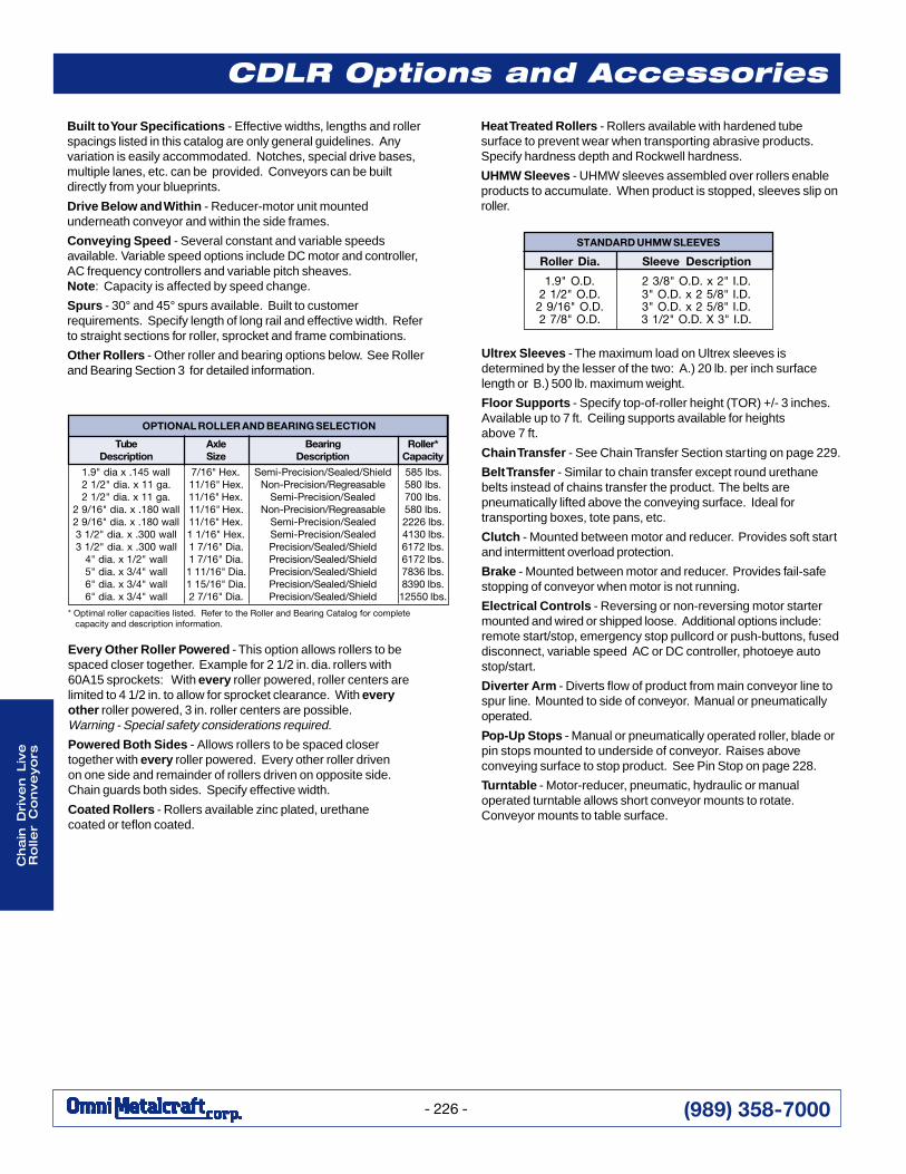
* Optimal roller capacities listed. Refer to the Roller and Bearing Catalog for complete capacity and description information.
Built to Your Specifications - Effective widths, lengths and rollerspacings listed in this catalog are only general guidelines. Anyvariation is easily accommodated. Notches, special drive bases,multiple lanes, etc. can be provided. Conveyors can be builtdirectly from your blueprints.
Drive Below and Within - Reducer-motor unit mountedunderneath conveyor and within the side frames.
Conveying Speed - Several constant and variable speedsavailable. Variable speed options include DC motor and controller,AC frequency controllers and variable pitch sheaves.Note : Capacity is affected by speed change.
Spurs - 30° and 45° spurs available. Built to customerrequirements. Specify length of long rail and effective width. Referto straight sections for roller, sprocket and frame combinations.
Other Rollers - Other roller and bearing options below. See Rollerand Bearing Section 3 for detailed information.
Ultrex Sleeves - The maximum load on Ultrex sleeves isdetermined by the lesser of the two: A.) 20 lb. per inch surfacelength or B.) 500 lb. maximum weight.
Floor Supports - Specify top-of-roller height (TOR) +/- 3 inches.Available up to 7 ft. Ceiling supports available for heightsabove 7 ft.
Chain Transfer - See Chain Transfer Section starting on page 229.
Belt Transfer - Similar to chain transfer except round urethanebelts instead of chains transfer the product. The belts arepneumatically lifted above the conveying surface. Ideal fortransporting boxes, tote pans, etc.
Clutch - Mounted between motor and reducer. Provides soft startand intermittent overload protection.
Brake - Mounted between motor and reducer. Provides fail-safestopping of conveyor when motor is not running.
Electrical Controls - Reversing or non-reversing motor startermounted and wired or shipped loose. Additional options include:remote start/stop, emergency stop pullcord or push-buttons, fuseddisconnect, variable speed AC or DC controller, photoeye autostop/start.
Diverter Arm - Diverts flow of product from main conveyor line tospur line. Mounted to side of conveyor. Manual or pneumaticallyoperated.
Pop-Up Stops - Manual or pneumatically operated roller, blade orpin stops mounted to underside of conveyor. Raises aboveconveying surface to stop product. See Pin Stop on page 228.
Turntable - Motor-reducer, pneumatic, hydraulic or manualoperated turntable allows short conveyor mounts to rotate.Conveyor mounts to table surface.
Tube Axle Bearing Roller*Description Size Description Capacity
1.9" dia x .145 wall 7/16" Hex. Semi-Precision/Sealed/Shield 585 lbs.2 1/2" dia. x 11 ga. 11/16" Hex. Non-Precision/Regreasable 580 lbs.2 1/2" dia. x 11 ga. 11/16" Hex. Semi-Precision/Sealed 700 lbs.
2 9/16" dia. x .180 wall 11/16" Hex. Non-Precision/Regreasable 580 lbs.2 9/16" dia. x .180 wall 11/16" Hex. Semi-Precision/Sealed 2226 lbs.3 1/2" dia. x .300 wall 1 1/16" Hex. Semi-Precision/Sealed 4130 lbs.3 1/2" dia. x .300 wall 1 7/16" Dia. Precision/Sealed/Shield 6172 lbs.
4" dia. x 1/2" wall 1 7/16" Dia. Precision/Sealed/Shield 6172 lbs.5" dia. x 3/4" wall 1 11/16" Dia. Precision/Sealed/Shield 7836 lbs.6" dia. x 3/4" wall 1 15/16" Dia. Precision/Sealed/Shield 8390 lbs.6" dia. x 3/4" wall 2 7/16" Dia. Precision/Sealed/Shield 12550 lbs.
OPTIONAL ROLLER AND BEARING SELECTION
Roller Dia. Sleeve Description
1.9" O.D. 2 3/8" O.D. x 2" I.D.2 1/2" O.D. 3" O.D. x 2 5/8" I.D.
2 9/16" O.D. 3" O.D. x 2 5/8" I.D.2 7/8" O.D. 3 1/2" O.D. X 3" I.D.
STANDARD UHMW SLEEVES

(989) 358-7000
Cha
in D
rive
n L
ive
Ro
ller C
on
ve
yo
rs
- 227 -
CDLR Drive Options
DRIVE MOUNTED HIGH
DRIVE MOUNTED LOWDRIVE MOUNTED
BELOW AND WITHIN
DRIVE MOUNTED HIGH
DRIVE MOUNTEDBELOW AND WITHIN
DRIVEGUARD
DRIVEGUARD
DRIVEGUARD
DRIVEGUARD
DRIVEGUARD
Zero Pressure CDLR Drive Options

(989) 358-7000
Cha
in D
rive
n L
ive
Ro
ller
Co
nve
yo
rs
- 228 -
CDLR Accessories
Guards have been removedto show more detail.
■ Designed for round products such as barrels,pails, tires, etc. Controls flow of product byreleasing one at a time.
■ Mounted to CDLR straight sections.
■ Pneumatically operated device.
■ Built to customer requirements. Specifyconveyor effective width, between frame width,channel size, product diameter and productheight.
■ Optional equipment includes limit switches forarm positioning and pneumatic valves.
Escapement Device
■ Bolts in line with CDLR straight sections. Allowsround product to negotiate corners in a conveyorsystem.
■ Built to customer requirements. Specify effectivewidth, roller diameter and spacing, speed and driverequirements.
■ Available with flow rail, drip pans and hold downs.
Square 90° Transfer
Chain Transfer Device■ Bolts in line with CDLR straight sections. Transfers
product 90° to adjacent conveying line. Ideal fortransporting loaded pallets or products with a sturdyconveying surface.
■ Powered chains are pneumatically lifted above rollersurface.
■ Can be built within frame or to span multiple conveyors.
■ Built to customer requirements. Specify effective width,length, roller diameter and spacing, number of chainstrands, chain speed and drive requirements.
■ Optional equipment includes limit switches for up/downpositioning and pneumatic valves.
Pin Stop■ Designed for round products such as barrels,
pails, tires, etc.
■ Mounted to CDLR straight sections.
■ Pneumatically operated pins protrude betweenrollers to stop product in conveying line.
■ Built to customer requirements. Specify productdiameter and height, conveyor effective width,between frame width, channel size, rollerdiameter and spacing.
■ Optional equipment includes limit switches forup/down positioning and pneumatic valves.